WO2012128205A1 - 通信システム、基地局装置、移動局装置、移動局装置処理能力の管理方法および集積回路 - Google Patents
通信システム、基地局装置、移動局装置、移動局装置処理能力の管理方法および集積回路 Download PDFInfo
- Publication number
- WO2012128205A1 WO2012128205A1 PCT/JP2012/056853 JP2012056853W WO2012128205A1 WO 2012128205 A1 WO2012128205 A1 WO 2012128205A1 JP 2012056853 W JP2012056853 W JP 2012056853W WO 2012128205 A1 WO2012128205 A1 WO 2012128205A1
- Authority
- WO
- WIPO (PCT)
- Prior art keywords
- mobile station
- station apparatus
- base station
- station device
- processing capability
- Prior art date
- Legal status (The legal status is an assumption and is not a legal conclusion. Google has not performed a legal analysis and makes no representation as to the accuracy of the status listed.)
- Ceased
Links
Images





Classifications
-
- H—ELECTRICITY
- H04—ELECTRIC COMMUNICATION TECHNIQUE
- H04W—WIRELESS COMMUNICATION NETWORKS
- H04W8/00—Network data management
- H04W8/22—Processing or transfer of terminal data, e.g. status or physical capabilities
-
- H—ELECTRICITY
- H04—ELECTRIC COMMUNICATION TECHNIQUE
- H04W—WIRELESS COMMUNICATION NETWORKS
- H04W72/00—Local resource management
- H04W72/04—Wireless resource allocation
Definitions
- the present invention relates to a communication system, a base station apparatus, a mobile station apparatus, a communication method, and an integrated circuit, and more particularly, to a communication method in which a mobile station apparatus notifies a base station apparatus of its own communication processing capability.
- 3GPP 3rd Generation Partnership Project
- 3GPP which is a standardization project, has evolved to realize high-speed communication by adopting OFDM (Orthogonal Frequency Frequency Division) Multiplexing (OFDM) communication method and flexible scheduling in predetermined frequency and time units called resource blocks Universal Terrestrial Radio Access (hereinafter referred to as EUTRA) has been studied, and further development of Advanced EUTRA (also referred to as LTE-Advanced) is underway.
- OFDM Orthogonal Frequency Frequency Division
- EUTRA Universal Terrestrial Radio Access
- Carrier Aggregation has been proposed as a technology that enables higher-speed data transmission while maintaining compatibility with EUTRA.
- Carrier aggregation is a method of receiving data of a transmitting device transmitted in a plurality of different frequency bands (also referred to as carrier frequency and component carrier) by receiving devices corresponding to different frequency bands. It is a technology that improves the rate.
- carrier aggregation can divide one frequency band into a plurality of frequency resources to be component carriers.
- a receiving device in downlink transmission is referred to as a mobile station device
- a transmitting device is referred to as a base station device
- a receiving device in uplink transmission is a base station device
- a transmitting device in uplink transmission is a base station device
- a transmitting device in uplink transmission is a base station device
- mobile station apparatuses but the scope of application of the present invention need not be limited to these apparatuses.
- Component carriers used in Advanced EUTRA carrier aggregation are classified into primary component carriers (PCC: Primary Component Carrier) and secondary component carriers (SCC: Secondary Component Carrier), and mobile station devices are connected by downlink PCC.
- a cell is called a primary cell (PCell: ellPrimary Cell), and a cell connected by a downlink SCC is called a secondary cell (SCell: Secondary Cell).
- the primary cell always includes an uplink component carrier, but may not be included in the secondary cell.
- MIMO Multiple Input Multiple Output
- transmission data is divided into a plurality of signals (streams) in advance in a transmitting apparatus, and these are simultaneously transmitted from a plurality of antennas in the same frequency band, and the divided signals are transmitted using a plurality of antennas in a receiving apparatus.
- This method is called spatial multiplexing or SM (Spatial (Multiplexing) because it is equivalent to generating a plurality of independent spatial channels by performing signal processing such as least square error method (MMSE).
- SM spatial multiplexing
- MMSE least square error method
- This spatial channel is also called a spatial layer from the image of dividing a radio propagation path into several layers and transmitting radio signals in parallel in each layer.
- the number of carrier aggregation component carriers and the number of MIMO spatial layers that can be supported by the mobile station apparatus may differ depending on the number of receivers and antennas of the mobile station apparatus and the frequency band to be used.
- the mobile station apparatus includes a first receiver and a second receiver each having two antennas
- downlink communication is performed only in the first frequency band as shown in FIG. 11A.
- the first receiver and the second receiver in the first frequency band and supports 4 component carriers and 4 MIMO spatial layers.
- the number of component carriers in the first frequency band is 4, and the number of MIMO spatial layers is 2, in order to assign the second receiver to the second frequency band.
- the number of component carriers in the second frequency band is 4 and the number of MIMO spatial layers is 2.
- Patent Document 1 a mechanism has been proposed in which the mobile station apparatus notifies the base station apparatus of information (processing capability) such as the number of component carriers and the number of spatial layers supported for each frequency band to be used and combinations of frequency bands (non-capable).
- NodeB Node B
- eNodeB the base station apparatus in EUTRA and Advanced EUTRA
- the base station apparatus manages a cell that is an area where the mobile station apparatus can communicate, and the cell is also referred to as a femto cell, a pico cell, or a nano cell depending on the size of the area that can communicate with the mobile station apparatus.
- the cell of the base station device is a serving cell of the mobile station device, and other base station devices or cells of different frequencies are referred to as neighboring cells. Is done.
- Non-Patent Document 1 proposes to notify the base station apparatus of the processing capability for each frequency band and each combination of frequency bands supported by the mobile station apparatus. Further, the processing capability notified to the base station apparatus is notified from the base station apparatus to the switching center (MME), maintained during the connection state with the MME (ECM_Connected), and updated if the contents are changed.
- MME switching center
- ECM_Connected the switching center
- the present invention provides a communication system, a base station apparatus, a mobile station apparatus, a mobile station apparatus processing capacity management method, and an integrated circuit that can efficiently notify and manage the processing capacity of a mobile station apparatus. For the purpose.
- the communication system of the present invention is a communication system including a mobile station apparatus, a base station apparatus, and an exchange station that manages the mobile station apparatus, and the mobile station apparatus can transmit and receive by itself.
- the base station apparatus is notified of the processing capacity for each frequency band and each combination of frequency bands, and the base station apparatus performs the processing when the processing capacity notified from the mobile station apparatus is notified to the exchange. A part of the capability is notified to the exchange.
- the communication system of the present invention is a communication system including a mobile station device, a base station device, and an exchange station that manages the mobile station device, and the base station device is a cell of its own station.
- the processing capacity of the mobile station apparatus is acquired and held from the exchange, and the base station apparatus is not included in the acquired processing capacity
- the mobile station apparatus is inquired about additional processing capability, and the mobile station apparatus In response to the inquiry, a target for additional notification is extracted from the processing capability of the own station and notified to the base station apparatus.
- the processing capability notified from the exchange is a processing capability for each frequency band that can be transmitted and received by the mobile station device, and is added to the mobile station device.
- the processing capacity to be inquired is a processing capacity for each combination of frequency bands that can be transmitted and received by the mobile station apparatus.
- the communication system of the present invention is a communication system including a mobile station device, a base station device, and an exchange station that manages the mobile station device, and the base station device is a cell of its own station.
- the processing capacity of the mobile station apparatus is acquired and held from the exchange, and the mobile station apparatus is based on a combination of frequency bands from the base station apparatus.
- the wireless communication is set, the mobile station apparatus is inquired about the additional processing capacity from the base station apparatus or which processing capacity is notified from the base station apparatus to the switching center
- the base station device is notified of the processing capability for the combination. And butterflies.
- the base station apparatus of the present invention is a base station apparatus that performs radio communication with a mobile station apparatus, and the base station apparatus can transmit and receive a frequency band and a frequency band that can be transmitted and received by the mobile station apparatus.
- a mobile station device processing capability information management unit that acquires and manages the processing capability for each combination from the mobile station device or an exchange that manages the mobile station device, and the mobile station device processing capability information management unit includes: When there is a possibility of performing wireless communication with the mobile station apparatus using a combination of frequency bands not included in the retained processing capacity, the mobile station apparatus is inquired about additional processing capacity.
- the base station apparatus of this invention is a base station apparatus which performs radio
- the said base station apparatus is a frequency band and frequency band which the said mobile station apparatus can transmit / receive
- a mobile station device processing capability information management unit that acquires and manages the processing capability for each combination from the mobile station device or an exchange that manages the mobile station device, and the mobile station device processing capability information management unit includes: When wireless communication using a combination of frequency bands not included in the retained processing capacity is set for the mobile station apparatus, the mobile station apparatus is inquired about the additional processing capacity and notified from the mobile station apparatus It is characterized by retaining the processing capability.
- the mobile station apparatus of the present invention is a mobile station apparatus that performs radio communication with the base station apparatus, and the mobile station apparatus has a frequency band and a frequency band that can be transmitted and received by the local station.
- a processing capability information holding unit that manages the processing capability for each combination separately into basic information and additional information, and when the request for addition notification is included in the message for inquiring processing capability from the base station device, the addition Information is notified to the base station apparatus.
- the mobile station apparatus processing capacity management method of the present invention is a mobile station apparatus processing capacity management method in a communication system comprising a mobile station apparatus, a base station apparatus, and an exchange station that manages the mobile station apparatus.
- the base station device acquiring and holding the processing capability of the mobile station device from the exchange when communication to a mobile station device in a standby state occurs in the cell of the base station device;
- a step of inquiring the mobile station apparatus for additional processing capacity In response to an inquiry from the base station apparatus, the mobile station apparatus includes a step of extracting a target to be added from its own processing capacity and notifying the base station apparatus.
- the mobile station apparatus processing capacity management method of the present invention is a mobile station apparatus processing capacity management method in a communication system comprising a mobile station apparatus, a base station apparatus, and an exchange station that manages the mobile station apparatus.
- the base station device acquiring and holding the processing capability of the mobile station device from the exchange when communication to a mobile station device in a standby state occurs in the cell of the base station device;
- the base station device makes a wireless communication based on a combination of frequency bands, an inquiry about additional processing capability is made from the base station device, or any processing capability is
- notification from the base station apparatus to the switching center is known in the mobile station apparatus, and communication of combinations of frequency bands not included in the known processing capability is set in the own station , Characterized in that it comprises the steps of performing notification processing capacity for the combination to the base station apparatus.
- An integrated circuit according to the present invention is an integrated circuit that acquires and manages a mobile station apparatus processing capability of a base station apparatus that performs radio communication with a mobile station apparatus, and the mobile station apparatus transmits and receives. Wireless communication based on a combination of frequency bands that are acquired from the mobile station apparatus or an exchange that manages the mobile station apparatus and holds the processing capacity for each possible frequency band and frequency band combination, and that are not included in the held processing capacity
- the mobile station apparatus has a mobile station apparatus processing capacity information management unit that makes an inquiry about additional processing capacity to the mobile station apparatus.
- the present invention it is possible to provide a communication system, a base station device, a mobile station device, a transmission method, and an integrated circuit that can efficiently notify and manage the processing capability of the mobile station device.
- the physical channel includes a downlink channel in the downlink transmitted from the base station apparatus to the mobile station apparatus, and an uplink channel in the uplink transmitted from the mobile station apparatus to the base station apparatus.
- the physical channel may be added or changed in the future in EUTRA and Advanced EUTRA. However, even if the physical channel is changed, the description of each embodiment of the present invention is not affected.
- the synchronization signal (Synchronization Signals) is composed of three types of primary synchronization signals and secondary synchronization signals composed of 31 types of codes arranged alternately in the frequency domain.
- 504 kinds of cell identifiers (cell ID: PhysicalPhysCell Identity; PCI) for identifying the base station apparatus and frame timing for radio synchronization are shown.
- the mobile station device specifies the cell ID of the synchronization signal received by the cell search.
- the physical broadcast information channel is transmitted for the purpose of reporting control parameters (broadcast information (system information); System information) that are commonly used by mobile station apparatuses in the cell. Broadcast information that is not notified by the physical broadcast information channel is transmitted by a layer 3 message using the downlink data channel, in which radio resources are notified by the downlink control channel.
- a cell global identifier CGI; “Cell Global Identifier”
- TAI tracking area identifier
- the downlink reference signal is a pilot signal transmitted at a predetermined power for each cell.
- the downlink reference signal is a known signal that is periodically repeated at a frequency / time position based on a predetermined rule.
- the mobile station apparatus measures the reception quality for each cell by receiving the downlink reference signal.
- the mobile station apparatus also uses the downlink reference signal as a reference signal for demodulation of the downlink control channel or downlink data channel transmitted simultaneously with the downlink reference signal.
- a sequence used for the downlink reference signal a sequence that can be identified for each cell is used.
- a downlink reference signal may be described as cell specific RS (Cell-specific reference
- the downlink control channel (PDCCH: Physical Downlink Control Channel) is transmitted in several OFDM symbols from the beginning of each subframe, and is transmitted to the mobile station device by radio resource allocation information according to the scheduling of the base station device or transmission Used to indicate the amount of power increase / decrease adjustment.
- the mobile station apparatus monitors (monitors) the downlink control channel addressed to itself before transmitting / receiving the layer 3 message (paging, handover command, etc.) that is downlink data or downlink control data, and By receiving the downlink control channel, it is necessary to acquire radio resource allocation information called an uplink grant at the time of transmission and a downlink grant at the time of reception.
- the downlink data channel (PDSCH: Physical Downlink Shared Channel) is used to notify paging and broadcast information as a layer 3 message that is downlink control data in addition to downlink data.
- the radio resource allocation information of the downlink data channel is indicated by the downlink control channel.
- the uplink data channel (PUSCH: Physical Uplink Shared Channel) mainly transmits uplink data and uplink control data, and can also include control data such as downlink reception quality and ACK / NACK. Similarly to the downlink, the radio resource allocation information of the uplink data channel is indicated by the downlink control channel.
- PUSCH Physical Uplink Shared Channel
- the random access channel (PRACH; “Physical” Random “Access” Channel) is a channel used to notify the preamble sequence and has a guard time.
- the random access channel is used as a means for accessing the base station apparatus of the mobile station apparatus.
- the mobile station apparatus uses a random access channel for a request for scheduling transmission data when the uplink control channel is not set and a request for transmission timing adjustment information necessary for matching the uplink transmission timing with the reception timing window of the base station apparatus. .
- the mobile station apparatus that has received the transmission timing adjustment information sets an effective time of the transmission timing adjustment information, and is in a transmission timing adjustment state during the effective time and in a transmission timing non-adjustment state outside the effective period. Since other physical channels are not related to each embodiment of the present invention, detailed description thereof is omitted.
- Carrier aggregation is a technology that aggregates (aggregates) a plurality of different frequency bands (component carriers) and treats them as a single frequency band. For example, when five component carriers having a frequency bandwidth of 20 MHz are aggregated by carrier aggregation, the mobile station apparatus can access the mobile station apparatus by regarding it as a frequency bandwidth of 100 MHz.
- the component carriers to be aggregated may be a continuous frequency band or a frequency band in which all or part of the component carriers are discontinuous.
- the usable frequency band is the 800 MHz band, the 2.4 GHz band, and the 3.4 GHz band
- one component carrier is the 800 MHz band
- another component carrier is the 2 GHz band
- another component carrier is 3.4 GHz. It may be a band.
- each component carrier may be a frequency bandwidth narrower than 20 MHz, or may be different from each other.
- the base station device Based on various factors such as the processing capacity of the mobile station device, the amount of data buffer that remains, the reception quality of the mobile station device, the load in the cell and QoS, the base station device assigns the uplink or The number of downlink component carriers can be increased or decreased.
- FIG. 1 is a diagram illustrating an example of a communication network configuration according to an embodiment of the present invention.
- the communication network configuration has one base
- the station apparatus 2 includes transmitters 21 to 23 (and receivers 24 to 26 (not shown)) for each of a plurality of frequency bands, and the configuration in which control of each frequency band is performed by one base station apparatus 2 simplifies the control.
- the base station apparatus 2 transmits a single frequency band with a plurality of transmitters, or transmits a plurality of frequency bands with a single transmitter because the frequency bands are continuous. You may be the structure to perform.
- the communicable range of each frequency band controlled by the transmitter of the base station apparatus 2 is regarded as a cell and exists in the same spatial area. At this time, the areas (cells) covered by each frequency band may have different sizes and shapes. Further, the mobile station apparatus 1 includes receivers 14 to 16 (and transmitters 11 to 13 (not shown)) to perform communication with the base station apparatus 2 by carrier aggregation.
- the mobile station apparatus 1 may also have a configuration in which a plurality of receivers receive a single frequency band or a configuration in which a single receiver receives a plurality of frequency bands.
- each area covered by the frequency of the component carrier formed by the base station apparatus 2 will be referred to as a cell, but this may be different from the definition of the cell in the actually operated communication system. Note that there is sex.
- a part of component carriers used by carrier aggregation may be defined as merely an additional radio resource instead of a cell.
- the component carrier as a cell in the present invention, even if a case different from the definition of the cell in the actually operated communication system occurs, the gist of the present invention is not affected.
- the mobile station device 1 may be wirelessly connected to the base station device 2 via a relay station device (or repeater).
- FIG. 2A shows the correspondence between the downlink component carrier and the uplink component carrier that the base station device 2 sets for the mobile station device 1 when the mobile station device 1 according to the embodiment of the present invention performs carrier aggregation. It is the figure which showed an example of the relationship.
- the downlink component carrier DL_CC1 and the uplink component carrier UL_CC1, the downlink component carrier DL_CC2 and the uplink component carrier UL_CC2, and the downlink component carrier DL_CC3 and the uplink component carrier UL_CC3 are cell-specific connected (Sell Specific Linkage).
- the cell-specific connection is, for example, a correspondence relationship (linkage relationship) between uplink and downlink frequency bands accessible to the base station device 2 when the mobile station device 1 is not carrier-aggregated. Is indicated by the notification information.
- the relationship between the uplink and downlink frequency bands is specified explicitly as frequency information in broadcast information, or when it is not explicitly specified, the uplink and downlink specifications that are uniquely determined for each operating frequency It is implicitly instructed by using frequency difference information. In addition to these methods, other methods may be used as long as the correspondence relationship between uplink and downlink frequency bands can be shown for each cell.
- the base station apparatus 2 can also individually set the correspondence relationship between the downlink component carrier and the uplink component carrier for each mobile station apparatus separately from the cell-specific connection (individual connection: UE Specific Linkage). It is.
- the dedicated connection is set at the same time when a downlink component carrier and an uplink component carrier are added from the base station apparatus 2.
- two downlink component carriers correspond to an uplink component carrier UL_CC2 to which a certain mobile station apparatus 1 is wirelessly connected, and DL_CC3 and UL_CC2 are individually connected.
- DL_CC1 and DL_CC2 are cell-specific connected to UL_CC1 and UL_CC2, respectively.
- the mobile station apparatus 1 performs reception processing with DL_CC1 to DL_CC3, and performs transmission processing with UL_CC1 and UL_CC2.
- DL_CC1 to DL_CC3 and UL_CC1 to UL_CC2 are connection component carriers used by the mobile station device 1 for communication with the base station device 2, and UL_CC3 is not used by the mobile station device 1 for communication with the base station device 2.
- Connection component carrier typically, the uplink and downlink of the primary cell are cell-specific connected, and the uplink and downlink of the secondary cell are individually connected.
- the reception quality of the downlink component carrier (the power of the radio signal transmitted from the base station apparatus 2 is received by the mobile station apparatus 1)
- the path loss value indicating the amount of attenuation until the first time is used.
- the downlink reception quality of the primary cell is used for transmission power adjustment of the primary cell.
- the transmission power adjustment of the secondary cell is based on either the primary cell or the downlink reception quality of the secondary cell. Whether the downlink reception quality of the primary cell or the secondary cell is used for adjusting the transmission power of the secondary cell is determined based on broadcast information or an individual layer 3 message (RRC message) for each mobile station apparatus. A notification is sent from the station device 2 to the mobile station device 1.
- RRC message individual layer 3 message
- Random access procedure There are two access methods for random access: Contention based Random Access and Non-contention based Random Access.
- the Contention based Random Access is a random access that may collide between mobile station apparatuses, and is a random access that is normally performed during connection processing.
- Non-contention based Random Access is a random access in which no collision occurs between mobile station devices, and is a random access used to quickly synchronize between a mobile station device and a base station device, such as a handover. This is done in the special case of the base station equipment.
- a random access preamble (also simply referred to as a preamble) is transmitted through a random access channel in order to achieve uplink synchronization (adjustment of uplink synchronization timing).
- the preamble includes a signature which is a signal pattern representing information, and several tens of types of signatures can be prepared to express several bits of information.
- 6-bit information is transmitted, and it is assumed that 64 types of signatures are prepared.
- the 6-bit information is determined based on the random ID, 5 bits are the random ID, the remaining 1 bit is the downlink path loss, and the amount of uplink data to be transmitted after random access.
- FIG. 3 is a sequence chart showing a procedure example of Contention based Random Access. Contention based Random Access is used for initial access, reconnection, Inter-RAT handover, and so on.
- step S51 the mobile station apparatus receives broadcast information from the base station apparatus, and acquires signature information (such as radio resource information of a random access channel and signature group information) for selecting a signature to be transmitted.
- signature information such as radio resource information of a random access channel and signature group information
- step S52 a signature is selected based on the signature information, and the selected preamble is transmitted to the base station apparatus using the random access channel (step S53).
- the base station apparatus calculates an uplink synchronization timing shift (Timing Advance) between the mobile station apparatus and the base station apparatus from the transmitted preamble, and a random access response (random access response) Mobile station apparatus that performs scheduling to transmit a message, assigns temporary C-RNTI (Cell-Radio Network Temporary Identity) as a temporary identifier to the mobile station apparatus, and transmits a preamble to the downlink shared control channel (PDCCH) RA-RNTI (Random Access-Radio Network Temporary Identity) that is an identifier indicating a response addressed to and a downlink data channel resource allocation information are arranged, and uplink synchronization timing shift information, uplink scheduling information, Temporary are assigned to the downlink data channel (PDSCH).
- the mobile station apparatus When the mobile station apparatus confirms that the downlink shared control channel (PDCCH) has RA-RNTI, the mobile station apparatus confirms the content of the random access response arranged in the downlink data channel (PDSCH), and transmits the signature ID number ( (Or random ID) is extracted. Then, the uplink synchronization timing deviation is corrected, and uplink scheduling data including Temporary C-RNTI is transmitted using the scheduled radio resource (step S55). Note that the mobile station apparatus continues to wait for a random access response from the base station apparatus for a certain period, and when it does not receive the random access response including the signature ID number of the transmitted preamble, it transmits the preamble again.
- the mobile station apparatus continues to wait for a random access response from the base station apparatus for a certain period, and when it does not receive the random access response including the signature ID number of the transmitted preamble, it transmits the preamble again.
- the base station apparatus uses the Temporary C-RNTI included in the received uplink scheduling data to determine whether the mobile station apparatus has a collision between the mobile station apparatuses.
- Downlink scheduling data to be transmitted to the mobile station apparatus (step S56).
- the downlink scheduling data is also called contention resolution.
- the mobile station apparatus determines that the random access has succeeded by correctly receiving the downlink scheduling data within the time limit, and ends the random access procedure.
- Temporary C-RNTI is not temporary, but is used as an identifier (C-RNT) for identifying the mobile station apparatus in the cell.
- the base station apparatus selects a signature ID number and notifies the mobile station apparatus.
- the mobile station apparatus uses the notified signature and transmits a preamble using a random access channel.
- the base station device Upon receiving the preamble from the mobile station device, the base station device calculates a synchronization timing shift between the mobile station device and the base station device from the preamble, and transmits the random access channel to the downlink shared control channel (PDCCH)
- PDCCH downlink shared control channel
- a C-RNTI is arranged to indicate a response addressed to the device, and a random access response including synchronization timing shift information is transmitted.
- the mobile station apparatus corrects the synchronization timing shift from the received random access response, and determines that the random access has been correctly completed.
- the mobile station apparatus notifies the base station apparatus of the processing capability including the number of component carriers and the number of MIMO layers that can be supported for each frequency band and each combination of frequency bands based on a request from the base station apparatus.
- the processing capability notification / management method of the mobile station apparatus described in Non-Patent Document 2 is shown in FIG.
- the base station apparatus transmits a mobile station apparatus capability inquiry message (RRC: UECapabilityEnquiry), which is an RRC message for inquiring processing capability to the mobile station apparatus (step S91).
- the mobile station apparatus capability inquiry message includes information on which communication system (RAT; “Radio” Access ”technology) is requested to be notified.
- the mobile station apparatus that has received the message indicates the processing capability of the mobile station regarding the requested RAT (for example, EUTRAN, UTRAN, GERAN-PS, GERAN-CS, CDMA2000-1XRTT, etc.), and the mobile station apparatus capability information message (RRC: UECapability Information) is used to notify the base station apparatus (step S92).
- the requested RAT for example, EUTRAN, UTRAN, GERAN-PS, GERAN-CS, CDMA2000-1XRTT, etc.
- RRC UECapability Information
- the base station apparatus retains the processing capability of the mobile station apparatus during the RRC_CONNECTED state connected to the mobile station apparatus.
- the base station apparatus uses the mobile station apparatus capability information notification message (S1-AP: UE CAPABILITY INFO INDICATION) of the S1-AP message used for communication with the switching center (MME) to the MME that manages the mobile station apparatus.
- the processing capability of the mobile station apparatus is notified (step S93).
- the processing capability of the mobile station apparatus is held in the memory of the MME while being connected to the MME (ECM_Connected), and if the mobile station apparatus capability information notification message is notified again from the base station apparatus, the contents of the memory Is updated.
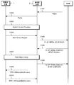
- FIG. 5 is a sequence chart showing a mobile station calling procedure when starting communication with a mobile station apparatus in an ECM_Connected standby (RRC_IDLE) state.
- the MME transmits a paging message for calling the mobile station device to the base station device in the standby area (tracking area) where the location of the mobile station device is registered (step S1001). All base station apparatuses that have received the Paging message from the MME wirelessly transmit a paging signal addressed to the mobile station apparatus in the cell of the local station (step S1002). The mobile station apparatus that has received the Paging signal performs a random access procedure and connects to the base station apparatus of the cell in which the mobile station is waiting (step S1003).
- the connected mobile station apparatus transmits a service request message (NAS: Service Request), which is a NAS (Non-Access-Stratum) message used for communication with the MME, to the connected base station apparatus (Step S1004) and receives it.
- the base station apparatus which made the notification notifies the MME of the initial mobile station apparatus message (S1-AP: INITIAL UE MESSAGE) including the service request message (step S1005).
- the MME that has received the initial mobile station device message transmits an initial context setup request (S1-AP: INITIAL CONTEXT SETUP REQUEST) to the base station device (step S1006).
- This message includes a general mobile station apparatus context (General UE context), a radio access bearer context (E-RAB Context), and the like, and includes the processing capability of the mobile station apparatus.
- the base station device that has received the initial context setup request sets up the context of the target mobile station device and performs necessary processing such as radio bearer setup (step S1007).
- the base station device transmits an initial context setup completion message (S1-AP: INITIALMCONTEXT ⁇ ⁇ SETUP ⁇ ⁇ COMPLETE) to the MME (step S1008). If the connection fails, an initial context setup failure message (S1-AP: INITIAL CONTEXT SETUP FAILURE) is sent.
- S1-AP INITIAL CONTEXT SETUP FAILURE
- the base station apparatus transmits a mobile station apparatus capability inquiry message to the mobile station apparatus in order to acquire the processing capability of another RAT as necessary (step S1009), and receives the mobile station apparatus capability information message. (Step S1010). According to the above procedure, since the base station apparatus does not need to acquire processing capability from the mobile station apparatus directly using radio resources, it is possible to improve the efficiency of radio resource utilization.
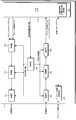
- FIG. 6 is a block diagram showing an example of the mobile station apparatus according to the embodiment of the present invention.
- the mobile station apparatus 1 includes a reception unit 101, a demodulation unit 102, a decoding unit 103, a measurement processing unit 104, a control unit 105, a random access processing unit 106, a coding unit 107, a modulation unit 108, a transmission unit 109, an upper layer 110, a processing
- the capability information holding unit 111 is configured.
- mobile station apparatus control information Prior to reception, mobile station apparatus control information is input from the upper layer 110 to the control unit 105, and the mobile station apparatus control information related to reception is received as reception control information.
- the reception unit 101, demodulation unit 102, decoding unit 103, and measurement processing unit 104 Is entered appropriately.
- the reception control information includes information such as demodulation information, decoding information, reception frequency band information, reception timing for each channel, multiplexing method, and radio resource arrangement information as reception schedule information.
- the received signal is received by the receiving unit 101.
- the receiving unit 101 receives a signal in the frequency band notified by the reception control information.
- the received signal is input to demodulator 102.
- Demodulation section 102 demodulates the received signal and inputs the received signal to decoding section 103.
- the decoding unit 103 correctly decodes the received signal based on the reception control information. Decoding section 103 appropriately separates the received signal into downlink traffic data and downlink control data, and inputs the separated signals to higher layer 110, respectively.
- the decoding unit 103 inputs a decoded received signal related to measurement to the measurement processing unit 104.
- the measurement processing unit 104 performs measurement processing of the reception quality of the downlink reference signal for each cell and measurement processing of the reception error rate of the downlink control channel or the downlink data channel, and averages the measured reception quality for each sample. (Filtered) downlink measurement information is generated, and the downlink measurement information is output to the upper layer 110.
- the measurement processing unit 104 compares the obtained reception quality with a threshold value (also referred to as Qout) used for detecting a downlink synchronization error, and determines the downlink synchronization error and the downlink synchronization recovery as necessary. Output to.
- a threshold value also referred to as Qout
- mobile station apparatus control information is input from the upper layer 110 to the control section 105, and the mobile station apparatus control information related to transmission is transmitted to the random access processing section 106, encoding section 107, modulation section 108, and transmission section 109 as transmission control information. Entered appropriately.
- the transmission control information includes information such as encoding information, modulation information, transmission frequency band information, transmission timing for each channel, multiplexing method, and radio resource arrangement information as uplink scheduling information of the transmission signal.
- Random access processing unit 106 receives random access information necessary for transmission of a random access channel such as random access radio resource information and the maximum number of transmissions from upper layer 110.
- the random access processing unit 106 detects the random access problem by counting the number of transmissions of the random access channel, the random access processing unit 106 notifies the upper layer 110 of random access problem information indicating that the random access problem has occurred.
- the encoding unit 107 receives uplink traffic data and uplink control data from the upper layer 110, and random access data from the random access processing unit 106.
- the encoding unit 107 appropriately encodes each data according to the transmission control information and outputs the data to the modulation unit 108.
- the modulation unit 108 modulates the input from the coding unit 107.
- the transmission unit 109 maps the output of the modulation unit 108 to the frequency domain, converts the frequency domain signal into a time domain signal, performs power amplification on a predetermined frequency carrier wave, and transmits the signal.
- the transmission unit 109 and the reception unit 101 are called a transmitter and a receiver in combination with an antenna (not shown), respectively, and a plurality of mobile station apparatuses 1 are used to perform communication in the same or different frequency bands.
- a transmitter or a receiver may be provided.
- Other components of the mobile station apparatus 1 are not related to the present embodiment, and are omitted.
- FIG. 7 is a block diagram showing an example of the base station apparatus according to the embodiment of the present invention.
- the base station apparatus 2 has functions of a reception unit 201, a demodulation unit 202, a decoding unit 203, a control unit 204, a coding unit 205, a modulation unit 206, a transmission unit 207, a network signal transmission / reception unit 208, an upper layer 210, and an upper layer 210.
- the mobile station apparatus processing capability information management unit 209 is included.
- the higher layer 210 inputs downlink traffic data and downlink control data to the encoding unit 205.
- the encoding unit 205 encodes each input data and inputs the data to the modulation unit 206.
- Modulation section 206 modulates the encoded signal.
- the downlink reference signal is multiplexed with the modulated signal and mapped to the frequency domain.
- the transmission unit 207 converts the frequency domain signal output from the modulation unit 206 into a time domain signal, places the converted signal on a carrier wave of a predetermined frequency, and performs power amplification and transmission.
- a downlink data channel in which downlink control data is arranged typically constitutes a layer 3 message (RRC message).
- the receiving unit 201 converts the received signal from the mobile station apparatus 1 into a baseband digital signal.
- the digital signal is input to the demodulation unit 202 and demodulated.
- the signal demodulated by the demodulator 202 is subsequently input to the decoder 203 and decoded.
- the decoding unit 203 appropriately separates the received signal into uplink traffic data and uplink control data, and inputs each to the higher layer 210.
- Base station apparatus control information necessary for the control of each block is input from the upper layer 210 to the control unit 204, and the base station apparatus control information related to transmission is transmitted from the control unit 204 as transmission control information as a coding unit 205, modulation.
- Base station apparatus control information related to reception is appropriately input to each block of the reception unit 201, demodulation unit 202, and decoding unit 203 as reception control information in each block of the unit 206 and transmission unit 207.
- the network signal transmission / reception unit 208 transmits or receives a control message between the base station devices 2 or between the control station device (or gateway device) or the MME and the base station device 2. Control messages are transmitted and received via a network line.
- the mobile station apparatus processing capacity information management unit 209 acquires the processing capacity from the MME or the mobile station apparatus 1 and holds the acquired processing capacity.
- the mobile station apparatus processing capability information management unit 209 notifies all or part of the processing capability to the MME that manages the mobile station apparatus 1 through the network signal transmission / reception unit 208.
- the mobile station device processing capability information management unit 209 deletes the information of the mobile station device 1.
- the upper layer 210 manages the network signal transmitting / receiving unit 208.
- the RRC of the base station device 2 exists as a part of the upper layer 210.
- the other constituent elements of the base station apparatus 2 are not related to the present embodiment, and are omitted.
- the MME (not shown) holds information on the mobile station apparatus 1 in the ECM_Connected state on the memory (or other storage medium), acquires information from the base station apparatus 2 as necessary, and stores the information Update. Further, when a communication request for the mobile station apparatus 1 in the ECM_Connected state and the RRC_IDLE state is generated, the above-described mobile station calling procedure is performed.
- FIG. 8 is a sequence chart showing a method for notifying and managing the processing capability of the mobile station apparatus in this embodiment.
- the base station apparatus 2 includes the number of component carriers and the number of MIMO layers supported for each frequency band and combination of frequency bands of the mobile station apparatus 1. Get processing power.
- the base station apparatus 2 selects only the processing capacity for each frequency band from the acquired processing capacity (step S63), and notifies the MME with a mobile station apparatus capability information notification message (step S64).
- the MME holds the notified processing capability (step S65).
- FIG. 9 is a sequence chart showing a part of a mobile station calling procedure when starting communication with the mobile station apparatus 1 in the ECM_Connected standby (RRC_IDLE) state in the present embodiment.
- the processing up to the initial mobile station apparatus message transmission (steps S701 to S705) in FIG. 9 is the same as steps S1001 to S1005 in FIG.
- the MME notifies the base station apparatus 2 connected to the mobile station apparatus 1 of the processing capability for each frequency band of the mobile station apparatus 1 using an initial context setup request message (step S706).
- the base station apparatus 2 retains the processing capability.
- the base station apparatus 2 sets up the context of the target mobile station apparatus 1 and performs necessary processing such as radio bearer setup (step S708).
- the base station device 2 transmits an initial context setup completion message (S1-AP: INITIAL ⁇ ⁇ ⁇ ⁇ ⁇ ⁇ CONTEXT SETUP COMPLETE) to the MME when the connection with the mobile station device 1 is successful. If the connection fails, an initial context setup failure message (S1-AP: INITIAL CONTEXT SETUP FAILURE) is transmitted (step S709).
- S1-AP INITIAL CONTEXT SETUP FAILURE
- the base station apparatus 2 determines whether or not additional notification from the mobile station apparatus 1 is necessary based on whether the carrier aggregation process of the own station or the mobile station apparatus 1 is possible (step S710).
- the base station apparatus 2 gives the mobile station apparatus 1 other than the processing capability for each frequency band for a specific RAT.
- Mobile station apparatus capability inquiry message (Additional Info.
- Inquiry for inquiring information (information of processing capability for each combination of frequency bands) is transmitted (step S711), and the mobile station apparatus 1 that has received the mobile station capability inquiry message Then, the processing capability for each combination of frequency bands supported by the own station in the designated RAT is extracted (step S712), and the extracted processing capability (Additional Info) is notified to the base station apparatus 2 (step S713).
- the MME in the present embodiment holds only the processing capability for each frequency band supported by the mobile station apparatus 1 as basic information, and the base station apparatus 2 performs carrier aggregation using a plurality of frequency bands.
- the base station apparatus 2 performs carrier aggregation using a plurality of frequency bands.
- step S63 of FIG. 8 only the processing capability for each frequency band is selected as the basic information in step S63 of FIG. 8, but this is not limiting, and the processing capability for each combination of frequency bands is included. Also good.
- the basic information also includes the processing capability for each combination of the partial frequency bands, and the base station apparatus 2 uses the frequency other than the basic information held by itself in step S710. It is determined that additional notification is necessary when performing carrier aggregation using a combination of bands.
- the base station apparatus 2 acquires additional processing capacity (for each combination of frequency bands) using the mobile station apparatus capability inquiry message.
- the mobile station apparatus 1 moves the processing capacity in the combination of the frequency bands of the component carriers allocated to the mobile station apparatus 1 at that time to the base station apparatus 2. You may make it notify automatically.
- the base station device 2 can include information on whether or not it is necessary to notify the processing capability of the combination in the component carrier addition message, and the content held by the base station device 2 as basic information is If it is known in the mobile station device 1, it can be notified when the frequency band combination is not included in the basic information.
- the configurations of the mobile station apparatus and the base station apparatus used in the present embodiment may be the same as those of the mobile station apparatus 1 (FIG. 6) and the base station apparatus 2 (FIG. 7) of the first embodiment, respectively, and thus description thereof is omitted. .
- FIG. 10 is a sequence chart showing a processing capability notification / management method of the mobile station apparatus according to this embodiment.
- the base station apparatus 2 transmits to the mobile station apparatus 1 a mobile station apparatus capability inquiry message that inquires about the processing capability for each frequency band (step S81).
- the inquiry message includes information regarding which communication system (RAT; “Radio” Access ”technology) is requested and whether basic information or additional information is requested.
- the mobile station device 1 that has received the message requests the processing capability for each frequency band, if the basic information (Basic Info) is requested, among the processing capabilities of the local station related to the requested RAT, and requests additional information (Additional Info).
- step S82 the processing capacity for each combination of frequency bands is extracted (step S82), and the base station apparatus 2 is notified with a mobile station apparatus capability information message (step S83).
- the base station apparatus 2 retains the processing capability of the mobile station apparatus 1 during the RRC_CONNECTED state connected to the mobile station apparatus 1. Further, the base station apparatus 2 notifies the basic information of the processing capabilities of the mobile station apparatus 1 to the MME that manages the mobile station apparatus 1 with a mobile station apparatus capability information notification message (step S84).
- the processing capability of the mobile station apparatus 1 is held in the MME while being connected to the MME (ECM_Connected) (step S85).
- steps S711 to S713 in FIG. 9 are operations at the time of requesting additional information in steps S81 to S83 in FIG.
- the MME in the present embodiment holds only the processing capability for each frequency band supported by the mobile station apparatus 1 as basic information, and the base station apparatus 2 performs carrier aggregation using a plurality of frequency bands.
- the base station apparatus 2 performs carrier aggregation using a plurality of frequency bands.
- step S82 in FIG. 10 only the processing capability for each frequency band is selected as the basic information in step S82 in FIG. 10, but this is not limiting, and the processing capability for each combination of frequency bands is included. Also good.
- the basic information also includes the processing capability for each combination of the partial frequency bands, and the base station apparatus 2 uses the frequency other than the basic information held by itself in step S710. It is determined that additional notification is necessary when performing carrier aggregation using a combination of bands.
- the base station apparatus 2 acquires additional processing capacity (for each combination of frequency bands) using the mobile station apparatus capability inquiry message.
- the mobile station apparatus 1 moves the processing capacity in the combination of the frequency bands of the component carriers allocated to the mobile station apparatus 1 at that time to the base station apparatus 2. You may make it notify automatically.
- the base station device 2 can include information on whether or not it is necessary to notify the processing capability of the combination in the component carrier addition message, and the content held by the base station device 2 as basic information is Since it is known in the mobile station apparatus 1, it can be notified when the frequency band combination is not included in the basic information.
- the mobile station apparatus capability inquiry message in the present embodiment may be designed so that the basic information request, additional information only request, and all information request can be identified.
- the base station device 2 does not have the processing capability related to the mobile station device 1
- a message requesting all information is transmitted to the mobile station device 1
- the basic information of the acquired processing capability is sent to the MME.
- a message requesting basic information may be sent to the mobile station apparatus 1, the acquired processing capability is notified to the MME, and additional information is requested only when additional information is required for carrier aggregation. It is also possible to transmit a message to be transmitted to the mobile station apparatus 1.
- the mobile station device 1 and the base station device 2 of the embodiment have been described using functional block diagrams.
- the functions of each part of the mobile station device 1 and the base station device 2 or one of these functions Is recorded on a computer-readable recording medium, and the program recorded on the recording medium is read into a computer system and executed to control the mobile station apparatus and the base station apparatus.
- the “computer system” includes an OS and hardware such as peripheral devices.
- the “computer-readable recording medium” refers to a semiconductor medium (eg, RAM, nonvolatile memory card, etc.), an optical recording medium (eg, DVD, MO, MD, CD, BD, etc.), a magnetic recording medium (eg, , A magnetic tape, a flexible disk, etc.) and a storage device such as a disk unit built in a computer system. Furthermore, the “computer-readable recording medium” means that a program is dynamically held for a short time, like a communication line when a program is transmitted via a network such as the Internet or a communication line such as a telephone line.
- a network such as the Internet
- a communication line such as a telephone line.
- the program may be a program for realizing a part of the functions described above, and may be a program capable of realizing the functions described above in combination with a program already recorded in a computer system. .
- each functional block of the mobile station device 1 and the base station device 2 used in the above embodiments may be realized as an LSI that is typically an integrated circuit.
- Each functional block may be individually formed into chips, or a part or all of them may be integrated into a chip.
- the method of circuit integration is not limited to LSI, and may be realized by a dedicated circuit or a general-purpose processor.
- an integrated circuit based on the technology can also be used.
Landscapes
- Engineering & Computer Science (AREA)
- Databases & Information Systems (AREA)
- Computer Networks & Wireless Communication (AREA)
- Signal Processing (AREA)
- Mobile Radio Communication Systems (AREA)
Abstract
移動局装置1の処理能力を効率的に通知・管理できる通信システム、基地局装置2、移動局装置1、移動局装置処理能力の管理方法および集積回路を提供する。移動局装置1と基地局装置2と移動局装置1を管理する交換局とを具備する通信システムであって、移動局装置1は、自局が送受信することが可能な周波数帯域毎および周波数帯域の組み合わせ毎の処理能力を基地局装置2に通知し、基地局装置2は、移動局装置1から通知された処理能力を交換局に通知する際に、処理能力の一部を交換局に通知する。
Description
本発明は、通信システム、基地局装置、移動局装置、通信方法および集積回路に関し、特に、移動局装置が自局の通信処理能力を基地局装置に通知する通信方法に関する。
標準化プロジェクトである3GPP(3rd Generation Partnership Project)において、OFDM(Orthogonal Frequency-Division Multiplexing)通信方式やリソースブロックと呼ばれる所定の周波数・時間単位の柔軟なスケジューリングの採用によって、高速な通信を実現させたEvolved Universal Terrestrial Radio Access(以降EUTRAと称する)が検討され、更にその発展形であるAdvanced EUTRA(LTE-Advancedとも称される)の検討が進められている。
Advanced EUTRAでは、EUTRAとの互換性を維持しつつ、より高速なデータ伝送が可能な技術として、キャリア・アグリゲーション(Carrier Aggregation)が提案されている。キャリア・アグリゲーションとは、複数の異なる周波数帯域(キャリア周波数、コンポーネントキャリア(Component Carrier)とも称する)で送信された送信装置のデータを、異なる周波数帯域に対応する受信装置においてそれぞれ受信することで、データレートを向上させる技術である。また、キャリア・アグリゲーションは1つの周波数帯域を複数の周波数リソースに分割してコンポーネントキャリアとすることも可能である。
なお、以後は下りリンク送信における受信装置のことを移動局装置、送信装置のことを基地局装置と記載し、上りリンク送信における受信装置のことを基地局装置、上りリンク送信における送信装置のことを移動局装置と記載するが、本発明の適用範囲はこれらの装置に限定する必要は無い。
Advanced EUTRAのキャリア・アグリゲーションで用いられるコンポーネントキャリアは、プライマリコンポーネントキャリア(PCC: Primary Component Carrier)とセカンダリコンポーネントキャリア(SCC: Secondary Component Carrier)とに区別され、移動局装置が下りリンクのPCCで接続するセルをプライマリセル(PCell: Primary Cell)、下りリンクのSCCで接続するセルをセカンダリセル(SCell: Secondary Cell)と呼ぶ。プライマリセルには上りリンクコンポーネントキャリアが必ず含まれるが、セカンダリセルには含まれない場合がある。
また、EUTRAおよびAdvanced EUTRAでは、MIMO(Multiple Input Multiple Output)技術の利用が提案されている。MIMO技術とは、送信装置において送信データをあらかじめ複数の信号(ストリーム)に分割し、それらを複数のアンテナから同じ周波数帯域で同時送信し、受信装置において複数のアンテナを用いて前記分割された信号を同時受信して結合することで、データレートを向上させる技術である。
この手法は、最小二乗誤差法(MMSE)などの信号処理を行なうことで、複数の独立な空間チャネルを生成することに等しいことから、空間多重あるいはSM(Spatial Multiplexing)と呼ばれる。この空間チャネルは、無線伝搬路をいくつかの層に切り分けて、各々の層で無線信号を並列に伝送するというイメージから、空間レイヤとも呼ばれている。
ここで、移動局装置の持つ受信器やアンテナ数と使用する周波数帯域によって、移動局装置がサポートできるキャリア・アグリゲーションのコンポーネントキャリア数やMIMOの空間レイヤ数が異なる場合がある。
例えば、移動局装置がアンテナを2本ずつ持つ第1の受信器と第2の受信器を具備する仮定において、図11Aに示すように第1の周波数帯域のみで下りリンクの通信を行なう場合には、第1の受信器と第2の受信器を第1の周波数帯域で用いて、コンポーネントキャリア数は4、MIMOの空間レイヤ数は4をサポートするが、図11Bに示すように第1の周波数帯域と第2の周波数帯域を同時に用いる場合には、第2の受信器を第2の周波数帯域に割り当てるため、第1の周波数帯域のコンポーネントキャリア数は4、MIMOの空間レイヤ数は2をサポートし、第2の周波数帯域のコンポーネントキャリア数は4、MIMOの空間レイヤ数は2をサポートすることになる。
そのため、使用する周波数帯域や周波数帯域の組み合わせ毎にサポートするコンポーネントキャリア数や空間レイヤ数などの情報(処理能力)を移動局装置が基地局装置に対して通知する仕組みが提案されている(非特許文献1)。
なお、3GPPが規定する第3世代の基地局装置はノードB(NodeB)と称され、EUTRAおよびAdvanced EUTRAにおける基地局装置はイーノードB(eNodeB)と称される。基地局装置は移動局装置が通信可能なエリアであるセルを管理し、セルは移動局装置と通信可能なエリアの大きさに応じてフェムトセルやピコセル、ナノセルとも称される。
また、移動局装置がある基地局装置と通信可能であるとき、その基地局装置のセルは移動局装置の在圏セルであり、その他の基地局装置、または異なる周波数のセルは周辺セルと称される。
R2-110604,RAN WG2,3GPP TSG-RAN WG2 Meeting #72bis,Dublin,Ireland,17th-21th January 2011
TS 36.300,V10.2.0,3GPP TSG-RAN E-UTRA and E-UTRAN Overall description
前述のように、非特許文献1では、移動局装置がサポートする周波数帯域毎および周波数帯域の組み合わせ毎の処理能力を基地局装置へ通知することが提案されている。また、基地局装置に通知された前記処理能力は基地局装置から交換局(MME)へ通知され、MMEとの接続状態(ECM_Connected)の間は保持され、内容に変更があれば更新される。MMEで保持される前記処理能力の情報は移動局装置との通信時に該情報を保持していない基地局装置へ通知することにより、新たに移動局装置から基地局装置へ前記情報を通知するために無線リソースを使用することを抑制できる。
しかしながら、移動局装置がサポートするすべての組み合わせの処理能力をMMEで保持するのは多くのメモリを消費し、また基地局装置がサポートする周波数帯域が基地局装置毎に異なる場合があり、MMEからすべての情報を取得するのは非効率的である。
上記の課題を鑑みて、本発明は、移動局装置の処理能力を効率的に通知・管理できる通信システム、基地局装置、移動局装置、移動局装置処理能力の管理方法および集積回路を提供することを目的とする。
(1)上記の目的を達成するために、本発明は、以下のような手段を講じた。すなわち、本発明の通信システムは、移動局装置と基地局装置と前記移動局装置を管理する交換局とを具備する通信システムであって、前記移動局装置は、自局が送受信することが可能な周波数帯域毎および周波数帯域の組み合わせ毎の処理能力を前記基地局装置に通知し、前記基地局装置は、前記移動局装置から通知された前記処理能力を交換局に通知する際に、前記処理能力の一部を前記交換局に通知することを特徴とする。
(2)また、本発明の通信システムは、移動局装置と基地局装置と前記移動局装置を管理する交換局とを具備する通信システムであって、前記基地局装置は、自局のセルで待ち受け状態である移動局装置への通信が発生した際に、前記交換局から前記移動局装置の処理能力を取得して保持し、さらに前記基地局装置は、前記取得した処理能力に含まれない周波数帯域の組み合わせで前記移動局装置と無線通信を行なう可能性がある場合に、前記移動局装置に対して、追加の処理能力の照会を行ない、前記移動局装置は、前記基地局装置からの照会に対して、自局の処理能力から追加通知を行なう対象を抽出し、前記基地局装置に通知することを特徴とする。
(3)また、本発明の通信システムにおいて、前記交換局から通知される処理能力は、前記移動局装置が送受信することが可能な周波数帯域毎の処理能力であり、前記移動局装置へ追加で照会する処理能力は、前記移動局装置が送受信することが可能な周波数帯域の組み合わせ毎の処理能力であることを特徴とする。
(4)また、本発明の通信システムは、移動局装置と基地局装置と前記移動局装置を管理する交換局とを具備する通信システムであって、前記基地局装置は、自局のセルで待ち受け状態である移動局装置への通信が発生した際に、前記交換局から前記移動局装置の処理能力を取得して保持し、前記移動局装置は、前記基地局装置から周波数帯域の組み合わせによる無線通信が設定された際に、前記基地局装置から追加の処理能力の照会が行なわれた場合、または何れの処理能力が前記基地局装置から前記交換局へ通知されるかが前記移動局装置において既知であり、前記既知の処理能力に含まれない周波数帯域の組み合わせの通信が自局に設定された場合に、前記基地局装置に対して当該組み合わせに対する処理能力の通知を行なうことを特徴とする。
(5)また、本発明の基地局装置は、移動局装置と無線通信を行なう基地局装置であって、前記基地局装置は、前記移動局装置が送受信することが可能な周波数帯域および周波数帯域の組み合わせ毎の処理能力を前記移動局装置あるいは前記移動局装置を管理する交換局から取得して管理する移動局装置処理能力情報管理部を具備し、前記移動局装置処理能力情報管理部は、保持する処理能力に含まれない周波数帯域の組み合わせで前記移動局装置と無線通信を行なう可能性がある場合に、前記移動局装置に対して追加の処理能力の照会を行なうことを特徴とする。
(6)また、本発明の基地局装置は、移動局装置と無線通信を行なう基地局装置であって、前記基地局装置は、前記移動局装置が送受信することが可能な周波数帯域および周波数帯域の組み合わせ毎の処理能力を前記移動局装置あるいは前記移動局装置を管理する交換局から取得して管理する移動局装置処理能力情報管理部を具備し、前記移動局装置処理能力情報管理部は、保持する処理能力に含まれない周波数帯域の組み合わせによる無線通信を前記移動局装置に対して設定する場合に、前記移動局装置に対して追加の処理能力の照会を行ない、前記移動局装置から通知される処理能力を保持することを特徴とする。
(7)また、本発明の移動局装置は、前記基地局装置と無線通信を行なう移動局装置であって、前記移動局装置は、自局が送受信することが可能な周波数帯域および周波数帯域の組み合わせ毎の処理能力を基本情報と追加情報とに分けて管理する処理能力情報保持部を具備し、前記基地局装置から処理能力を照会するメッセージに追加通知の要求が含まれる場合には前記追加情報を前記基地局装置に通知することを特徴とする。
(8)また、本発明の移動局装置処理能力の管理方法は、移動局装置と基地局装置と前記移動局装置を管理する交換局とを具備する通信システムにおける移動局装置処理能力の管理方法であって、前記基地局装置において、自局のセルで待ち受け状態である移動局装置への通信が発生した際に、前記交換局から前記移動局装置の処理能力を取得して保持するステップと、前記取得した処理能力に含まれない周波数帯域の組み合わせで前記移動局装置と無線通信を行なう可能性がある場合に、前記移動局装置に対して、追加の処理能力の照会を行なうステップと、前記移動局装置は、前記基地局装置からの照会に対して、自局の処理能力から追加通知を行なう対象を抽出して前記基地局装置に通知するステップとを含むことを特徴とする。
(9)また、本発明の移動局装置処理能力の管理方法は、移動局装置と基地局装置と前記移動局装置を管理する交換局とを具備する通信システムにおける移動局装置処理能力の管理方法であって、前記基地局装置において、自局のセルで待ち受け状態である移動局装置への通信が発生した際に、前記交換局から前記移動局装置の処理能力を取得して保持するステップと、前記移動局装置において、前記基地局装置から周波数帯域の組み合わせによる無線通信が設定された際に、前記基地局装置から追加の処理能力の照会が行なわれた場合、または何れの処理能力が前記基地局装置から前記交換局へ通知されるかが前記移動局装置において既知であり、前記既知の処理能力に含まれない周波数帯域の組み合わせの通信が自局に設定された場合に、前記基地局装置に対して当該組み合わせに対する処理能力の通知を行なうステップとを含むことを特徴とする。
(10)また、本発明の集積回路は、移動局装置と無線通信を行なう基地局装置の移動局装置処理能力の取得と管理を行なう集積回路であって、前記移動局装置が送受信することが可能な周波数帯域および周波数帯域の組み合わせ毎の処理能力を前記移動局装置あるいは前記移動局装置を管理する交換局から取得して保持し、保持する処理能力に含まれない周波数帯域の組み合わせによる無線通信を前記移動局装置に対して設定する場合に、前記移動局装置に対して追加の処理能力の照会を行なう移動局装置処理能力情報管理部を具備することを特徴とする。
以上説明したように、本発明によれば、移動局装置の処理能力を効率的に通知・管理できる通信システム、基地局装置、移動局装置、送信方法および集積回路を提供することができる。
本発明の実施形態を説明する前に、本発明に関する物理チャネルとキャリア・アグリゲーション、処理能力の通知方法について説明する。
(1)物理チャネル
EUTRAおよびAdvanced EUTRAで使用される物理チャネル(または物理シグナル)について説明を行なう。物理チャネルは、基地局装置から移動局装置へ送信される下りリンクにおける下りリンクチャネルと、移動局装置から基地局装置へ送信される上りリンクにおける上りリンクチャネルとが存在する。物理チャネルは、EUTRA、およびAdvanced EUTRAにおいて、今後追加、または、その構造が変更される可能性もあるが、変更された場合でも本発明の各実施形態の説明には影響しない。
EUTRAおよびAdvanced EUTRAで使用される物理チャネル(または物理シグナル)について説明を行なう。物理チャネルは、基地局装置から移動局装置へ送信される下りリンクにおける下りリンクチャネルと、移動局装置から基地局装置へ送信される上りリンクにおける上りリンクチャネルとが存在する。物理チャネルは、EUTRA、およびAdvanced EUTRAにおいて、今後追加、または、その構造が変更される可能性もあるが、変更された場合でも本発明の各実施形態の説明には影響しない。
同期シグナル(Synchronization Signals)は、3種類のプライマリ同期シグナルと、周波数領域で互い違いに配置される31種類の符号から構成されるセカンダリ同期シグナルとで構成され、プライマリ同期シグナルとセカンダリ同期シグナルの信号の組み合わせによって、基地局装置を識別する504通りのセル識別子(セルID:Physical Cell Identity; PCI)と、無線同期のためのフレームタイミングが示される。移動局装置は、セルサーチによって受信した同期シグナルのセルIDを特定する。
物理報知情報チャネル(PBCH; Physical Broadcast Channel)は、セル内の移動局装置で共通に用いられる制御パラメータ(報知情報(システム情報);System information)を通知する目的で送信される。物理報知情報チャネルで通知されない報知情報は、下りリンク制御チャネルで無線リソースが通知され、下りリンクデータチャネルを用いてレイヤ3メッセージで送信される。報知情報として、セル個別の識別子を示すセルグローバル識別子(CGI; Cell Global Identifier)、ページングによる待ち受けエリアを管理するトラッキングエリア識別子(TAI; Tracking Area Identifier)などが通知される。
下りリンクリファレンスシグナルは、セル毎に所定の電力で送信されるパイロットシグナルである。また、下りリンクリファレンスシグナルは、所定の規則に基づき周波数・時間位置で周期的に繰り返される既知の信号である。移動局装置は、下りリンクリファレンスシグナルを受信することでセル毎の受信品質を測定する。また、移動局装置は、下りリンクリファレンスシグナルと同時に送信される下りリンク制御チャネル、または下りリンクデータチャネルの復調のための参照用の信号としても下りリンクリファレンスシグナルを使用する。下りリンクリファレンスシグナルに使用される系列は、セル毎に識別可能な系列が用いられる。なお、下りリンクリファレンスシグナルはセル固有RS(Cell-specific reference signals)と記載される場合もあるが、その用途と意味は同じである。
下りリンク制御チャネル(PDCCH; Physical Downlink Control Channel)は、各サブフレームの先頭からいくつかのOFDMシンボルで送信され、移動局装置に対して基地局装置のスケジューリングに従った無線リソース割当て情報や、送信電力の増減の調整量を指示する目的で使用される。移動局装置は、下りリンクデータや下りリンク制御データであるレイヤ3メッセージ(ページング、ハンドオーバーコマンドなど)を送受信する前に自局宛の下りリンク制御チャネルを監視(モニタ)し、自局宛の下りリンク制御チャネルを受信することで、送信時には上りリンクグラント、受信時には下りリンクグラントと呼ばれる無線リソース割当て情報を取得する必要がある。
下りリンクデータチャネル(PDSCH; Physical Downlink Shared Channel)は、下りリンクデータの他、下りリンク制御データであるレイヤ3メッセージとしてページングや報知情報を通知するためにも使用される。下りリンクデータチャネルの無線リソース割当て情報は、下りリンク制御チャネルで示される。
上りリンクデータチャネル(PUSCH; Physical Uplink Shared Channel)は、主に上りリンクデータと上りリンク制御データを送信し、下りリンクの受信品質やACK/NACKなどの制御データを含めることも可能である。また、下りリンクと同様に上りリンクデータチャネルの無線リソース割当て情報は、下りリンク制御チャネルで示される。
ランダムアクセスチャネル(PRACH; Physical Random Access Channel)は、プリアンブル系列を通知するために使用されるチャネルであり、ガードタイムを持つ。ランダムアクセスチャネルは、移動局装置の基地局装置へのアクセス手段として用いられる。移動局装置は、上りリンク制御チャネル未設定時の送信データのスケジューリング要求や、上りリンク送信タイミングを基地局装置の受信タイミングウィンドウに合わせるために必要な送信タイミング調整情報の要求にランダムアクセスチャネルを用いる。送信タイミング調整情報を受信した移動局装置は、送信タイミング調整情報の有効時間を設定し、有効時間中は送信タイミング調整状態、有効期間外は、送信タイミング非調整状態となる。なお、それ以外の物理チャネルは、本発明の各実施形態に関わらないため詳細な説明は省略する。
(2)キャリア・アグリゲーション
キャリア・アグリゲーションとは、複数の異なる周波数帯域(コンポーネントキャリア)を集約(アグリゲーション)して一つの周波数帯域のように扱う技術である。例えば、キャリア・アグリゲーションによって周波数帯域幅が20MHzのコンポーネントキャリアを5つ集約した場合、移動局装置は100MHzの周波数帯域幅とみなしてアクセスすることが可能となる。
キャリア・アグリゲーションとは、複数の異なる周波数帯域(コンポーネントキャリア)を集約(アグリゲーション)して一つの周波数帯域のように扱う技術である。例えば、キャリア・アグリゲーションによって周波数帯域幅が20MHzのコンポーネントキャリアを5つ集約した場合、移動局装置は100MHzの周波数帯域幅とみなしてアクセスすることが可能となる。
なお、集約するコンポーネントキャリアは連続した周波数帯域であっても、全てまたは一部が不連続となる周波数帯域であってもよい。例えば、使用可能な周波数帯域が800MHz帯域、2.4GHz帯域、3.4GHz帯域である場合、ある一つのコンポーネントキャリアが800MHz帯域、別のコンポーネントキャリアが2GHz帯域、さらに別のコンポーネントキャリアが3.4GHz帯域であってもよい。
また、同一周波数帯域、例えば2.4GHz帯域内の連続または不連続のコンポーネントキャリアを集約することも可能である。各コンポーネントキャリアの周波数帯域幅は20MHzより狭い周波数帯域幅であっても良く、各々異なっていても良い。
基地局装置は、移動局装置の処理能力、滞留しているデータバッファ量や移動局装置の受信品質、セル内の負荷やQoSなどの種々の要因に基づいて、移動局装置に割り当てる上りリンクまたは下りリンクのコンポーネントキャリアの数を増減することができる。
[本発明の通信ネットワーク構成の例]
図1は、本発明の実施形態に係る通信ネットワーク構成の一例を示す図である。移動局装置1は、キャリア・アグリゲーションによって複数の周波数帯域(コンポーネントキャリア、Band1~Band3)を同時に用いて基地局装置2と無線接続することが可能な場合、通信ネットワーク構成としては、ある一つの基地局装置2が複数の周波数帯域毎に送信器21~23(および図示しない受信器24~26)を備えており、各周波数帯域の制御を一つの基地局装置2で行なう構成が制御の簡略化の観点から好適である。ただし、基地局装置2が複数の送信器で一つの周波数帯域の送信を行なう構成や、複数の周波数帯域が連続する周波数帯域であるなどの理由で一つの送信器で複数の周波数帯域の送信を行なう構成であっても構わない。
図1は、本発明の実施形態に係る通信ネットワーク構成の一例を示す図である。移動局装置1は、キャリア・アグリゲーションによって複数の周波数帯域(コンポーネントキャリア、Band1~Band3)を同時に用いて基地局装置2と無線接続することが可能な場合、通信ネットワーク構成としては、ある一つの基地局装置2が複数の周波数帯域毎に送信器21~23(および図示しない受信器24~26)を備えており、各周波数帯域の制御を一つの基地局装置2で行なう構成が制御の簡略化の観点から好適である。ただし、基地局装置2が複数の送信器で一つの周波数帯域の送信を行なう構成や、複数の周波数帯域が連続する周波数帯域であるなどの理由で一つの送信器で複数の周波数帯域の送信を行なう構成であっても構わない。
基地局装置2の送信器によって制御される各周波数帯域の通信可能範囲はセルとしてみなされ、空間的に同一のエリアに存在する。このとき、各周波数帯域がカバーするエリア(セル)はそれぞれ異なる広さ、異なる形状であっても良い。また移動局装置1は受信器14~16(および図示しない送信器11~13)を備えることで前記基地局装置2とのキャリア・アグリゲーションによる通信を行なう。
移動局装置1についても、複数の受信器で一つの周波数帯域の受信を行なう構成や、一つの受信器で複数の周波数帯域の受信を行なう構成であっても構わない。
後述する記載において、基地局装置2が形成するコンポーネントキャリアの周波数でカバーされるエリアのことをそれぞれセルと称して説明するが、これは実際に運用される通信システムにおけるセルの定義とは異なる可能性があることに注意する。
例えば、ある通信システムでは、キャリア・アグリゲーションによって用いられるコンポーネントキャリアの一部のことを、セルではなく単なる追加の無線リソースと定義するかもしれない。本発明でコンポーネントキャリアをセルと称することで、実際に運用される通信システムにおけるセルの定義と異なる場合が発生したとしても、本発明の主旨には影響しない。なお、移動局装置1は、リレー局装置(またはリピーター)を介して基地局装置2と無線接続されても良い。
[コンポーネントキャリアの構成の設定例]
図2Aは、本発明の実施形態に係る移動局装置1がキャリア・アグリゲーションを行なう場合に、基地局装置2が移動局装置1に対して設定する下りリンクコンポーネントキャリアと、上りリンクコンポーネントキャリアの対応関係の一例を示した図である。図2A中の下りリンクコンポーネントキャリアDL_CC1と上りリンクコンポーネントキャリアUL_CC1、下りリンクコンポーネントキャリアDL_CC2と上りリンクコンポーネントキャリアUL_CC2、および下りリンクコンポーネントキャリアDL_CC3と上りリンクコンポーネントキャリアUL_CC3はセル固有接続(Sell Specific Linkage)している。セル固有接続とは、例えば、移動局装置1がキャリア・アグリゲーションしていない場合に、基地局装置2にアクセス可能な上りリンクと下りリンクの周波数帯域の対応関係(連携関係)であり、典型的には報知情報でその対応関係が示される。
図2Aは、本発明の実施形態に係る移動局装置1がキャリア・アグリゲーションを行なう場合に、基地局装置2が移動局装置1に対して設定する下りリンクコンポーネントキャリアと、上りリンクコンポーネントキャリアの対応関係の一例を示した図である。図2A中の下りリンクコンポーネントキャリアDL_CC1と上りリンクコンポーネントキャリアUL_CC1、下りリンクコンポーネントキャリアDL_CC2と上りリンクコンポーネントキャリアUL_CC2、および下りリンクコンポーネントキャリアDL_CC3と上りリンクコンポーネントキャリアUL_CC3はセル固有接続(Sell Specific Linkage)している。セル固有接続とは、例えば、移動局装置1がキャリア・アグリゲーションしていない場合に、基地局装置2にアクセス可能な上りリンクと下りリンクの周波数帯域の対応関係(連携関係)であり、典型的には報知情報でその対応関係が示される。
上りリンクと下りリンクの周波数帯域の対応関係は、報知情報に周波数情報として明示的に指示されるか、または明示的に指示されない場合に運用周波数毎に一意に決められる上りリンクと下りリンクの規定の周波数差の情報を用いるなどして暗黙的に指示される。これらの方法に限らず、セル毎に上りリンクと下りリンクの周波数帯域の対応関係を示すことが可能であれば、これ以外の方法を用いて指示されても良い。
これに対し、基地局装置2は、下りリンクコンポーネントキャリアと上りリンクコンポーネントキャリアの対応関係を、セル固有接続とは別に移動局装置毎に個別に設定(個別接続;UE Specific Linkage)することも可能である。個別接続は、基地局装置2から下りリンクコンポーネントキャリアと上りリンクコンポーネントキャリアが追加されるときに同時に設定される。
図2Bの場合、ある移動局装置1が無線接続される上りリンクコンポーネントキャリアUL_CC2に対し、2つの下りリンクコンポーネントキャリア(DL_CC2、DL_CC3)が対応しており、DL_CC3とUL_CC2は個別接続されており、DL_CC1とDL_CC2はそれぞれUL_CC1とUL_CC2にセル固有接続されている。この場合、移動局装置1はDL_CC1~DL_CC3で受信処理を行ない、UL_CC1およびUL_CC2で送信処理を行なう。
すなわち、DL_CC1~DL_CC3とUL_CC1~UL_CC2は、移動局装置1が基地局装置2との通信に用いる接続コンポーネントキャリアであり、UL_CC3は、移動局装置1が基地局装置2との通信に用いない非接続コンポーネントキャリアである。典型的にはプライマリセルの上りリンクと下りリンクはセル固有接続され、セカンダリセルの上りリンクと下りリンクは個別接続される。
さらに、上りリンクコンポーネントキャリアで移動局装置1が送信する際の送信電力調整には、下りリンクコンポーネントキャリアの受信品質(基地局装置2から送信された無線信号の電力が移動局装置1で受信されるまでに減衰した量を示すパスロス値など)が用いられる。
プライマリセルの送信電力調整には、当該プライマリセルの下りリンクの受信品質が用いられる。一方、セカンダリセルの送信電力調整には、プライマリセルか当該セカンダリセルの下りリンクの受信品質のいずれか一方に基づく。セカンダリセルの送信電力調整のために、プライマリセルと当該セカンダリセルの何れの下りリンクの受信品質を利用するかは、報知情報あるいは移動局装置毎に個別のレイヤ3メッセージ(RRCメッセージ)によって、基地局装置2から移動局装置1へ通知される。
(3)ランダムアクセス手順
ランダムアクセスには、Contention based Random AccessとNon-contention based Random Accessの2つのアクセス方法がある。Contention based Random Accessは、移動局装置間で衝突する可能性のあるランダムアクセスであり、接続処理時に通常行なわれるランダムアクセスである。
ランダムアクセスには、Contention based Random AccessとNon-contention based Random Accessの2つのアクセス方法がある。Contention based Random Accessは、移動局装置間で衝突する可能性のあるランダムアクセスであり、接続処理時に通常行なわれるランダムアクセスである。
また、Non-contention based Random Accessは、移動局装置間で衝突が発生しないランダムアクセスであり、迅速に移動局装置-基地局装置間の同期をとるために用いられるランダムアクセスであり、ハンドオーバー等の特別な場合に基地局装置主導で行なわれる。
Contention based Random Accessでは、上り同期を取る(上り同期タイミングを調整する)ためにランダムアクセスプリアンブル(単にプリアンブルとも呼ばれる)をランダムアクセスチャネルで送信する。プリアンブルには、情報を表す信号パターンであるシグネチャが含まれ、数十種類のシグネチャを用意して数ビットの情報を表現することができる。
EUTRAでは、6ビットの情報を送信することが想定され、64種類のシグネチャが用意されることが想定されている。6ビットの情報は、5ビットがランダムID、残りの1ビットが下りリンクのパスロスとランダムアクセス後に送信する上りデータ量に基づき決定される。
ここで、Contention based Random AccessおよびNon-Contention based Random Accessの通信手順の概略について説明する。
図3は、Contention based Random Accessの手順例について示したシーケンスチャートである。Contention based Random Accessは、初期アクセス時、再接続時、Inter-RATハンドオーバー時などに用いられる。
移動局装置は、ステップS51で基地局装置から報知情報を受信し、送信するシグネチャを選択するためのシグネチャ情報(ランダムアクセスチャネルの無線リソース情報、シグネチャのグループ情報など)を取得する。そして、ランダムアクセス要求が発生した場合(ステップS52)、シグネチャ情報に基づいてシグネチャを選択し、ランダムアクセスチャネルを用いて選択したプリアンブルを基地局装置へ送信する(ステップS53)。
基地局装置は、移動局装置からランダムアクセスチャネルを受信すると、送信されたプリアンブルから移動局装置と基地局装置間の上り同期タイミングずれ(Timing Advance)を算出し、ランダムアクセス応答(ランダムアクセスレスポンス)を送信するためにスケジューリングを行ない、移動局装置に対して仮の識別子であるTemporary C-RNTI(Cell-Radio Network Temporary Identity)を割り当て、下り共用制御チャネル(PDCCH)にプリアンブルを送信した移動局装置宛の応答を示す識別子であるRA-RNTI(Random Access-Radio Network Temporary Identity)と下りデータチャネルのリソース割当て情報を配置し、下りデータチャネル(PDSCH)に上り同期タイミングずれ情報、上りスケジューリング情報、Tempolary C-RNTIおよび受信したプリアンブルのシグネチャID番号(またはランダムID)を配置し、ランダムアクセス応答として前記下り共用制御チャネルと前記下りデータチャネルを送信する(ステップS54)。
移動局装置は、下り共用制御チャネル(PDCCH)にRA-RNTIがあることを確認すると、下りデータチャネル(PDSCH)に配置されたランダムアクセス応答の中身を確認し、送信したプリアンブルのシグネチャID番号(またはランダムID)が含まれる応答を抽出する。そして、上り同期タイミングずれを補正し、スケジューリングされた無線リソースでTempolary C-RNTIを含む上りスケジューリングデータを送信する(ステップS55)。なお、移動局装置は、基地局装置からのランダムアクセス応答を一定期間待ち続け、送信したプリアンブルのシグネチャID番号を含んだランダムアクセス応答を受信しない場合は、再度、プリアンブルを送信する。
基地局装置は、移動局装置からの上りスケジューリングデータを受信すると、受信した上りスケジューリングデータに含まれるTempolary C-RNTIを使用して移動局装置間で衝突が起こっているかどうかを移動局装置に判断させるための下りスケジューリングデータを移動局装置に送信する(ステップS56)。前記下りスケジューリングデータは、コンテンションレゾリューションとも呼ばれる。移動局装置は、下りスケジューリングデータを制限時間内に正しく受信することにより、ランダムアクセスが成功したと判断し、ランダムアクセス手順を終了する。そして、Tempolary C-RNTIを一時的なものでなく、当該セルにおいて移動局装置を識別するための識別子(C-RNT)として使用する。
一方、Non-contention based Random Accessでは、基地局装置がシグネチャID番号を選択して移動局装置に通知する。移動局装置は、通知されたシグネチャを使用し、ランダムアクセスチャネルでプリアンブルを送信する。
基地局装置は、移動局装置からのプリアンブルを受信すると、プリアンブルから移動局装置-基地局装置間の同期タイミングずれを算出し、下り共用制御チャネル(PDCCH)に、ランダムアクセスチャネルを送信した移動局装置宛の応答を示すためにC-RNTIを配置し、同期タイミングずれ情報を含んだランダムアクセス応答を送信する。移動局装置は、受信したランダムアクセス応答から同期タイミングずれを補正し、ランダムアクセスが正しく完了したと判断する。
(4)処理能力の通知方法
移動局装置は、自局の持つ受信器やアンテナ数によって、同時に送受信を行なう周波数帯域毎および周波数帯域の組み合わせ毎にサポートできるコンポーネントキャリア数やMIMOのレイヤ数が異なる場合がある。そのため、移動局装置は基地局装置からの要求に基づいて基地局装置に周波数帯域毎および周波数帯域の組み合わせ毎にサポートできるコンポーネントキャリア数やMIMOのレイヤ数を含む処理能力を通知する。
移動局装置は、自局の持つ受信器やアンテナ数によって、同時に送受信を行なう周波数帯域毎および周波数帯域の組み合わせ毎にサポートできるコンポーネントキャリア数やMIMOのレイヤ数が異なる場合がある。そのため、移動局装置は基地局装置からの要求に基づいて基地局装置に周波数帯域毎および周波数帯域の組み合わせ毎にサポートできるコンポーネントキャリア数やMIMOのレイヤ数を含む処理能力を通知する。
非特許文献2に記載されている移動局装置の処理能力通知・管理方法を図4に示す。図4において、まず基地局装置は移動局装置に対して処理能力の照会をするRRCメッセージである移動局装置能力照会メッセージ(RRC:UECapabilityEnquiry)を送信する(ステップS91)。移動局装置能力照会メッセージには、どの通信システム(RAT; Radio Access technology)に関する通知を要求するかの情報が含まれる。
前記メッセージを受信した移動局装置は要求されたRAT(例えばEUTRAN、UTRAN、GERAN-PS、GERAN-CS、CDMA2000-1XRTTなど)に関する自局の処理能力を、移動局装置能力情報メッセージ(RRC:UECapability Information)を用いて基地局装置へ通知する(ステップS92)。要求されたRATがEUTRANの場合、移動局装置は前述の周波数帯域毎および周波数帯域の組み合わせ毎にサポートできるコンポーネントキャリア数やMIMOのレイヤ数を含む処理能力を通知する。
基地局装置は移動局装置と接続されたRRC_CONNECTED状態の間、該移動局装置の処理能力を保持する。また、基地局装置は、交換局(MME)との通信で用いられるS1-APメッセージの移動局装置能力情報通知メッセージ(S1-AP:UE CAPABILITY INFO INDICATION)で該移動局装置を管理するMMEに対して該移動局装置の処理能力を通知する(ステップS93)。該移動局装置の処理能力は、MMEと接続された状態(ECM_Connected)の間、MMEのメモリ内に保持され、再度、基地局装置から移動局装置能力情報通知メッセージの通知があればメモリの内容が更新される。
また、図5は、ECM_Connectedで待ち受け(RRC_IDLE)状態の移動局装置に対して通信を開始する際の移動局呼び出し手順を示したシーケンスチャートである。
図5において、MMEは移動局装置が位置登録されている待ち受けエリア(トラッキングエリア)の基地局装置に対して、移動局装置呼び出しのPagingメッセージを送信する(ステップS1001)。MMEから前記Pagingメッセージを受信したすべての基地局装置は、自局のセルにおいて移動局装置宛てのページング信号を無線送信する(ステップS1002)。前記Paging信号を受信した移動局装置は自局が待ち受けを行なっているセルの基地局装置に対してランダムアクセス手順を実施して接続する(ステップS1003)。
接続した移動局装置はMMEとの通信で用いられるNAS(Non-Access-Stratum)メッセージであるサービス要求メッセージ(NAS:Service Request)を接続した基地局装置に対して送信し(ステップS1004)、受信した基地局装置はMMEに対して初期移動局装置メッセージ(S1-AP:INITIAL UE MESSAGE)に前記サービス要求メッセージを含めて通知する(ステップS1005)。初期移動局装置メッセージを受信したMMEは基地局装置に対して初期コンテキストセットアップ要求(S1-AP:INITIAL CONTEXT SETUP REQUEST)を送信する(ステップS1006)。このメッセージには全般的な移動局装置コンテキスト(General UE Context)や無線アクセスベアラコンテキスト(E-RAB Context)などが含まれており、該移動局装置の処理能力も含まれる。前記初期コンテキストセットアップ要求を受信した基地局装置は、対象となる移動局装置のコンテキストをセットアップし、無線ベアラのセットアップなどの必要な処理を行なう(ステップS1007)。
その後、基地局装置はMMEに対して、移動局装置との接続が成功した場合には初期コンテキストセットアップ完了メッセージ(S1-AP:INITIAL CONTEXT SETUP COMPLETE)を送信し(ステップS1008)、移動局装置との接続が失敗した場合には初期コンテキストセットアップ失敗メッセージ(S1-AP:INITIAL CONTEXT SETUP FAILURE)を送信する。
また、基地局装置は必要に応じて他のRATの処理能力を取得するために、移動局装置に対して移動局装置能力照会メッセージを送信し(ステップS1009)、移動局装置能力情報メッセージを受信する(ステップS1010)。上記の手順によると、基地局装置は直接無線リソースを用いて移動局装置から処理能力を取得する必要がないため、無線リソース利用の効率化を図ることができる。
以上の事項を考慮しつつ、以下、添付図面に基づき、本発明の好適な実施形態について詳細に説明する。なお、本発明の説明において、本発明に関連した公知の機能や構成についての具体的な説明が、本発明の要旨を不明瞭にすると判定される場合には、その詳細な説明を省略する。
<第1の実施形態>
本発明の第1の実施形態について以下に説明する。
本発明の第1の実施形態について以下に説明する。
図6は、本発明の実施形態に係る移動局装置の一例を示すブロック図である。移動局装置1は、受信部101、復調部102、復号部103、測定処理部104、制御部105、ランダムアクセス処理部106、符号部107、変調部108、送信部109、上位レイヤ110、処理能力情報保持部111から構成される。受信に先立ち、上位レイヤ110より制御部105へ移動局装置制御情報が入力され、受信に関する移動局装置制御情報が受信制御情報として、受信部101、復調部102、復号部103、測定処理部104へ適切に入力される。受信制御情報は、受信スケジュール情報として、復調情報、復号化情報、受信周波数帯域の情報、各チャネルに関する受信タイミング、多重方法、無線リソース配置情報などの情報が含まれている。
受信信号は、受信部101において受信される。受信部101は、受信制御情報で通知された周波数帯域で信号を受信する。受信信号は復調部102へと入力される。復調部102は、受信信号を復調して復号部103へと受信信号を入力する。復号部103は、受信制御情報に基づき受信信号を正しく復号する。復号部103は、受信信号を下りリンクトラフィックデータと下りリンク制御データに適切に分離し、それぞれ上位レイヤ110へ入力する。
また、復号部103は測定に関する復号した受信信号を測定処理部104へ入力する。測定処理部104は、セル毎の下りリンクリファレンスシグナルの受信品質の測定処理や、下りリンク制御チャネルまたは下りリンクデータチャネルの受信誤り率の測定処理を行ない、測定した受信品質をサンプル毎に平均化(フィルタリング)した下りリンク測定情報を生成し、下りリンク測定情報を上位レイヤ110へ出力する。また、測定処理部104は、得られた受信品質と下りリンク同期誤りの検出に用いる閾値(Qoutとも呼ばれる)とを比較し、必要に応じて下りリンク同期誤りおよび下りリンク同期回復を上位レイヤ110へ出力する。
また、上位レイヤ110より制御部105へ移動局装置制御情報が入力され、送信に関する移動局装置制御情報が送信制御情報として、ランダムアクセス処理部106、符号部107、変調部108、送信部109へ適切に入力される。送信制御情報は、送信信号の上りリンクスケジューリング情報として、符号化情報、変調情報、送信周波数帯域の情報、各チャネルに関する送信タイミング、多重方法、無線リソース配置情報などの情報が含まれている。ランダムアクセス処理部106には、上位レイヤ110からランダムアクセスの無線リソース情報や最大送信回数などのランダムアクセスチャネルの送信に必要なランダムアクセス情報が入力される。
また、ランダムアクセス処理部106は、ランダムアクセスチャネルの送信回数をカウントすることで、ランダムアクセス問題を検出した場合、ランダムアクセス問題が発生したことを示すランダムアクセス問題情報を上位レイヤ110へ通知する。符号部107には、上位レイヤ110より上りリンクトラフィックデータと上りリンク制御データ、ランダムアクセス処理部106からランダムアクセスデータとが入力される。符号部107は送信制御情報に従い、各データを適切に符号化し、変調部108に出力する。変調部108は、符号部107からの入力を変調する。
送信部109は、変調部108の出力を周波数領域にマッピングすると共に、周波数領域の信号を時間領域の信号へ変換し、既定の周波数の搬送波にのせて電力増幅を行なうと共に送信する。また、図6において、送信部109および受信部101は図示していないアンテナと組み合わせて、それぞれ送信器、受信器と呼称し、同一あるいは異なる周波数帯域の通信を行なうために移動局装置1は複数の送信器や受信器を具備してもよい。また、その他の移動局装置1の構成要素は本実施形態に関係ないため省略する。
図7は、本発明の実施形態による基地局装置の一例を示すブロック図である。基地局装置2は、受信部201、復調部202、復号部203、制御部204、符号部205、変調部206、送信部207、ネットワーク信号送受信部208、上位レイヤ210、上位レイヤ210の機能に含まれる移動局装置処理能力情報管理部209から構成される。
上位レイヤ210は、下りリンクトラフィックデータと下りリンク制御データを符号部205へ入力する。符号部205は、入力された各データを符号化し、変調部206へ入力する。変調部206は、符号化した信号の変調を行なう。また、変調部206において、変調された信号に対して下りリンクリファレンスシグナルが多重され、周波数領域にマッピングされる。送信部207は、変調部206から出力された周波数領域の信号を時間領域の信号へ変換し、変換した信号を既定の周波数の搬送波にのせて電力増幅を行なうと共に送信する。下りリンク制御データが配置される下りリンクデータチャネルは、典型的にはレイヤ3メッセージ(RRCメッセージ)を構成する。
また、受信部201は、移動局装置1からの受信信号をベースバンドのディジタル信号に変換する。ディジタル信号は、復調部202へ入力されて復調される。復調部202で復調された信号は続いて復号部203へ入力されて復号される。復号部203は、受信信号を上りリンクトラフィックデータと上りリンク制御データに適切に分離し、それぞれ上位レイヤ210へ入力する。
これら各ブロックの制御に必要な基地局装置制御情報は、上位レイヤ210より制御部204へ入力され、制御部204より送信に関連する基地局装置制御情報は送信制御情報として、符号部205、変調部206、送信部207の各ブロックに、受信に関連する基地局装置制御情報は受信制御情報として、受信部201、復調部202、復号部203の各ブロックに適切に入力される。
一方、ネットワーク信号送受信部208は、基地局装置2間あるいは制御局装置(またはゲートウェイ装置)やMMEと基地局装置2との間の制御メッセージの送信または受信を行なう。制御メッセージはネットワーク回線を経由して送受信される。
移動局装置処理能力情報管理部209は、MMEあるいは移動局装置1から前記処理能力の取得を行ない、前記取得した処理能力を保持する。また移動局装置処理能力情報管理部209は、ネットワーク信号送受信部208を通じて当該移動局装置1を管理するMMEに対して前記処理能力のすべてあるいは一部の通知を行なう。また移動局装置処理能力情報管理部209は、移動局装置1との接続が終了した場合(移動局装置1がRRC_IDLE状態となった場合)、当該移動局装置1の情報を削除する。
ネットワーク信号送受信部208は上位レイヤ210が管理する。基地局装置2のRRCは、上位レイヤ210の一部として存在する。図7において、その他の基地局装置2の構成要素は本実施形態に関係ないため省略する。
図示していないMMEは、ECM_Connected状態にある移動局装置1に関する情報をメモリ(あるいはその他の記憶媒体)上に保持しており、必要に応じて基地局装置2から情報を取得して前記情報の更新を行なう。また、ECM_Connected状態かつRRC_IDLE状態にある前記移動局装置1に対する通信要求が発生した際には、前述の移動局呼び出し手順を実施する。
続いて、本実施形態における移動局装置の処理能力の通知・管理方法について図8および図9を参照して説明を行なう。
まず、図8は本実施形態における移動局装置の処理能力の通知・管理方法を示すシーケンスチャートである。ステップS61、S62では、図4のステップS91、S92と同様に、基地局装置2が、移動局装置1の周波数帯域毎および周波数帯域の組み合わせ毎にサポートするコンポーネントキャリア数やMIMOのレイヤ数を含む処理能力を取得する。次に基地局装置2は前記取得した処理能力のうち、周波数帯域毎の処理能力のみを選択して(ステップS63)、移動局装置能力情報通知メッセージでMMEへ通知する(ステップS64)。MMEでは通知された処理能力を保持する(ステップS65)。
次に、図9は本実施形態におけるECM_Connectedで待ち受け(RRC_IDLE)状態の移動局装置1に対して通信を開始する際の移動局呼び出し手順の一部を示したシーケンスチャートである。図9における初期移動局装置メッセージ送信までの処理(ステップS701~ステップS705)は図5のステップS1001~ステップS1005と同じ処理であるため説明を省略する。
MMEは移動局装置1が接続した基地局装置2に対して、初期コンテキストセットアップ要求メッセージで、移動局装置1の周波数帯域毎の処理能力を通知する(ステップS706)。基地局装置2は前記処理能力を保持する。次に基地局装置2は、対象となる移動局装置1のコンテキストをセットアップし、無線ベアラのセットアップなどの必要な処理を行なう(ステップS708)。
その後、基地局装置2はMMEに対して、移動局装置1との接続が成功した場合には初期コンテキストセットアップ完了メッセージ(S1-AP:INITIAL CONTEXT SETUP COMPLETE)を送信し、移動局装置1との接続が失敗した場合には初期コンテキストセットアップ失敗メッセージ(S1-AP:INITIAL CONTEXT SETUP FAILURE)を送信する(ステップS709)。
その後、基地局装置2は自局あるいは移動局装置1のキャリア・アグリゲーション処理の可否に基づき移動局装置1からの追加通知要否の判断を行なう(ステップS710)。追加通知が必要である場合(複数周波数帯域の組み合わせによるキャリア・アグリゲーションを行なう可能性がある場合)、基地局装置2は移動局装置1に対して、特定のRATに対する周波数帯域毎の処理能力以外の情報(周波数帯域の組み合わせ毎の処理能力の情報)を照会する移動局装置能力照会メッセージ(Additional Info Enquiry)を送信し(ステップS711)、前記移動局能力照会メッセージを受信した移動局装置1は、指定されたRATで自局がサポートする周波数帯域の組み合わせ毎の処理能力を抽出し(ステップS712)、抽出した処理能力(Additional Info)を基地局装置2に通知する(ステップS713)。
以上のように、本実施形態におけるMMEは、移動局装置1のサポートする周波数帯域毎の処理能力のみを基本情報として保持し、基地局装置2は複数周波数帯域を用いたキャリア・アグリゲーションを行なう場合にのみ基本情報以外の処理能力を移動局装置1から取得することで、MMEにおける記憶容量の軽減と基地局装置2との通信負荷の軽減、基地局装置2と移動局装置1間における不必要な処理能力の通知による無線リソースの浪費や移動局装置1の電力消費を軽減することが可能となる。
なお、上記説明では、図8のステップS63において基本情報として周波数帯域毎の処理能力のみを選択しているが、これに限らず、一部の周波数帯域の組み合わせ毎の処理能力を含めるようにしてもよい。この場合、図9のステップS707では前記一部の周波数帯域の組み合わせ毎の処理能力も基本情報に含まれることになり、基地局装置2はステップS710で、自局が保持する基本情報以外の周波数帯域の組み合わせによるキャリア・アグリゲーションを行なう際に追加通知が必要であると判断する。
また、図9のステップS711およびS712において基地局装置2は移動局装置能力照会メッセージを用いて追加の(周波数帯域の組み合わせ毎の)処理能力を取得しているが、これに限らず、実際に移動局装置1に対するコンポーネントキャリアが追加・削除される際に、移動局装置1が、その時点で移動局装置1に割り当てられたコンポーネントキャリアの周波数帯域の組み合わせにおける処理能力を基地局装置2に動的に通知するようにしてもよい。
この場合、基地局装置2から当該組み合わせにおける処理能力の通知が必要であるか否かの情報を、コンポーネントキャリア追加のメッセージに含めることもできるし、基本情報として基地局装置2が保持する内容が移動局装置1において既知である場合には、基本情報に含まれない周波数帯域の組み合わせである場合に通知することもできる。
<第2の実施形態>
本発明の第2の実施形態について以下に説明する。本実施形態は、移動局装置の処理能力の通知に関する別の例である。
本発明の第2の実施形態について以下に説明する。本実施形態は、移動局装置の処理能力の通知に関する別の例である。
本実施形態に用いる移動局装置と基地局装置の構成は、それぞれ第1の実施形態の移動局装置1(図6)と基地局装置2(図7)と同じ構成で良いため説明を省略する。
本実施形態における移動局装置の処理能力の通知・管理方法について図10および図9を参照して説明を行なう。
図10は本実施形態における移動局装置の処理能力の通知・管理方法を示すシーケンスチャートである。まず、基地局装置2は、移動局装置1に対して周波数帯域毎の処理能力を照会する移動局装置能力照会メッセージを送信する(ステップS81)。照会メッセージには、どの通信システム(RAT; Radio Access technology)に関する通知を要求するか、および基本情報か追加情報のどちらを要求するかの情報が含まれる。前記メッセージを受信した移動局装置1は要求されたRATに関する自局の処理能力のうち、基本情報(Basic Info)の要求であれば周波数帯域毎の処理能力を、追加情報(Additional Info)の要求であれば周波数帯域の組み合わせ毎の処理能力を抽出し(ステップS82)、移動局装置能力情報メッセージで基地局装置2へ通知する(ステップS83)。基地局装置2は移動局装置1と接続されたRRC_CONNECTED状態の間、該移動局装置1の処理能力を保持する。また、基地局装置2は、移動局装置能力情報通知メッセージで該移動局装置1を管理するMMEに対して該移動局装置1の処理能力のうち基本情報を通知する(ステップS84)。該移動局装置1の処理能力は、MMEと接続された状態(ECM_Connected)の間、MMEに保持される(ステップS85)。
次に、本実施形態におけるECM_Connectedで待ち受け(RRC_IDLE)状態の移動局装置1に対して通信を開始する際の移動局呼び出し手順について説明を行なう。本実施形態における移動局呼び出し手順は第1の実施形態と同様であるが、図9のステップS711~S713は、図10のステップS81~S83での追加情報の要求時の動作となる。
以上のように、本実施形態におけるMMEは、移動局装置1のサポートする周波数帯域毎の処理能力のみを基本情報として保持し、基地局装置2は複数周波数帯域を用いたキャリア・アグリゲーションを行なう場合にのみ基本情報以外の処理能力を移動局装置1から取得することで、MMEにおける記憶容量の軽減と基地局装置2との通信負荷の軽減、さらに移動局装置能力照会で基本情報と追加情報を分離することで、不必要な処理能力の通知による無線リソースの浪費や移動局装置1の電力消費を軽減することが可能となる。
なお、上記説明では、図10のステップS82において基本情報として周波数帯域毎の処理能力のみを選択しているが、これに限らず、一部の周波数帯域の組み合わせ毎の処理能力を含めるようにしてもよい。この場合、図9のステップS707では前記一部の周波数帯域の組み合わせ毎の処理能力も基本情報に含まれることになり、基地局装置2はステップS710で、自局が保持する基本情報以外の周波数帯域の組み合わせによるキャリア・アグリゲーションを行なう際に追加通知が必要であると判断する。
また、図9のステップS711およびS712において基地局装置2は移動局装置能力照会メッセージを用いて追加の(周波数帯域の組み合わせ毎の)処理能力を取得しているが、これに限らず、実際に移動局装置1に対するコンポーネントキャリアが追加・削除される際に、移動局装置1が、その時点で移動局装置1に割り当てられたコンポーネントキャリアの周波数帯域の組み合わせにおける処理能力を基地局装置2に動的に通知するようにしてもよい。この場合、基地局装置2から当該組み合わせにおける処理能力の通知が必要であるか否かの情報を、コンポーネントキャリア追加のメッセージに含めることもできるし、基本情報として基地局装置2が保持する内容が移動局装置1において既知であるため、基本情報に含まれない周波数帯域の組み合わせである場合に通知することもできる。
また、本実施形態における移動局装置能力照会メッセージは基本情報の要求、追加情報のみを要求、すべての情報を要求の3つを識別できるように設計してもよい。この場合、基地局装置2が移動局装置1に関する処理能力を保持していなければ、すべての情報を要求するメッセージを移動局装置1に送信して、取得した処理能力のうち基本情報をMMEに通知してもよいし、基本情報を要求するメッセージを移動局装置1に送信して、取得した処理能力をMMEに通知し、キャリア・アグリゲーションに追加情報が必要である場合のみに追加情報を要求するメッセージを移動局装置1に送信することも可能である。
なお、以上説明した実施形態は単なる例示に過ぎず、様々な変形例、置換例を用いて実現することができる。
また、説明の便宜上、実施形態の移動局装置1および基地局装置2を機能的なブロック図を用いて説明したが、移動局装置1および基地局装置2の各部の機能またはこれらの機能の一部を実現するためのプログラムをコンピュータ読み取り可能な記録媒体に記録して、この記録媒体に記録されたプログラムをコンピュータシステムに読み込ませ、実行することにより移動局装置や基地局装置の制御を行なっても良い。なお、ここでいう「コンピュータシステム」とは、OSや周辺機器等のハードウェアを含むものとする。
また、「コンピュータ読み取り可能な記録媒体」とは、半導体媒体(例えば、RAM、不揮発性メモリカード等)、光記録媒体(例えば、DVD、MO、MD、CD、BD等)、磁気記録媒体(例えば、磁気テープ、フレキシブルディスク等)等の可搬媒体、コンピュータシステムに内蔵されるディスクユニット等の記憶装置のことをいう。さらに、「コンピュータ読み取り可能な記録媒体」とは、インターネット等のネットワークや電話回線等の通信回線を介してプログラムを送信する場合の通信線のように、短時間の間、動的にプログラムを保持するもの、その場合のサーバやクライアントとなるコンピュータシステム内部の揮発性メモリのように、一定時間プログラムを保持しているものも含むものとする。また上記プログラムは、前述した機能の一部を実現するためのものであっても良く、さらに、前述した機能をコンピュータシステムに既に記録されているプログラムとの組み合わせで実現できるものであっても良い。
また、上記各実施形態に用いた移動局装置1および基地局装置2の各機能ブロックは、典型的には集積回路であるLSIとして実現してもよい。各機能ブロックは個別にチップ化してもよいし、一部または全部を集積してチップ化してもよい。また、集積回路化の手法はLSIに限らず専用回路または汎用プロセッサで実現しても良い。また、半導体技術の進歩によりLSIに代替する集積回路化の技術が出現した場合、当該技術による集積回路を用いることも可能である。
以上、この発明の実施形態について図面を参照して詳述してきたが、具体的な構成はこの実施形態に限られるものではなく、この発明の要旨を逸脱しない範囲の設計等も特許請求の範囲に含まれる。
1 移動局装置
2 基地局装置
14~16 受信器
21~23 送信器
101、201 受信部
102、202 復調部
103、203 復号部
104 測定処理部
105、204 制御部
106 ランダムアクセス処理部
107、205 符号部
108、206 変調部
109、207 送信部
110、210 上位レイヤ
111 処理能力情報保持部
208 ネットワーク信号送受信部
209 移動局装置処理能力情報管理部
2 基地局装置
14~16 受信器
21~23 送信器
101、201 受信部
102、202 復調部
103、203 復号部
104 測定処理部
105、204 制御部
106 ランダムアクセス処理部
107、205 符号部
108、206 変調部
109、207 送信部
110、210 上位レイヤ
111 処理能力情報保持部
208 ネットワーク信号送受信部
209 移動局装置処理能力情報管理部
Claims (10)
- 移動局装置と基地局装置と前記移動局装置を管理する交換局とを具備する通信システムであって、
前記移動局装置は、自局が送受信することが可能な周波数帯域毎および周波数帯域の組み合わせ毎の処理能力を前記基地局装置に通知し、
前記基地局装置は、前記移動局装置から通知された前記処理能力を交換局に通知する際に、前記処理能力の一部を前記交換局に通知することを特徴とする通信システム。 - 移動局装置と基地局装置と前記移動局装置を管理する交換局とを具備する通信システムであって、
前記基地局装置は、自局のセルで待ち受け状態である移動局装置への通信が発生した際に、前記交換局から前記移動局装置の処理能力を取得して保持し、
さらに前記基地局装置は、前記取得した処理能力に含まれない周波数帯域の組み合わせで前記移動局装置と無線通信を行なう可能性がある場合に、前記移動局装置に対して、追加の処理能力の照会を行ない、
前記移動局装置は、前記基地局装置からの照会に対して、自局の処理能力から追加通知を行なう対象を抽出し、前記基地局装置に通知することを特徴とする通信システム。 - 前記交換局から通知される処理能力は、前記移動局装置が送受信することが可能な周波数帯域毎の処理能力であり、前記移動局装置へ追加で照会する処理能力は、前記移動局装置が送受信することが可能な周波数帯域の組み合わせ毎の処理能力であることを特徴とする請求項2に記載の通信システム。
- 移動局装置と基地局装置と前記移動局装置を管理する交換局とを具備する通信システムであって、
前記基地局装置は、自局のセルで待ち受け状態である前記移動局装置への通信が発生した際に、前記交換局から前記移動局装置の処理能力を取得して保持し、
前記移動局装置は、前記基地局装置から周波数帯域の組み合わせによる無線通信が設定された際に、
前記基地局装置から追加の処理能力の照会が行なわれた場合、または何れの処理能力が前記基地局装置から前記交換局へ通知されるかが前記移動局装置において既知であり、前記既知の処理能力に含まれない周波数帯域の組み合わせの通信が自局に設定された場合に、前記基地局装置に対して当該組み合わせに対する処理能力の通知を行なうことを特徴とする請求項1に記載の通信システム。 - 移動局装置と無線通信を行なう基地局装置であって、
前記基地局装置は、前記移動局装置が送受信することが可能な周波数帯域および周波数帯域の組み合わせ毎の処理能力を前記移動局装置あるいは前記移動局装置を管理する交換局から取得して管理する移動局装置処理能力情報管理部を具備し、
前記移動局装置処理能力情報管理部は、保持する処理能力に含まれない周波数帯域の組み合わせで前記移動局装置と無線通信を行なう可能性がある場合に、前記移動局装置に対して追加の処理能力の照会を行なうことを特徴とする基地局装置。 - 移動局装置と無線通信を行なう基地局装置であって、
前記基地局装置は、
前記移動局装置が送受信することが可能な周波数帯域および周波数帯域の組み合わせ毎の処理能力を前記移動局装置あるいは前記移動局装置を管理する交換局から取得して管理する移動局装置処理能力情報管理部を具備し、
前記移動局装置処理能力情報管理部は、保持する処理能力に含まれない周波数帯域の組み合わせによる無線通信を前記移動局装置に対して設定する場合に、前記移動局装置に対して追加の処理能力の照会を行ない、前記移動局装置から通知される処理能力を保持することを特徴とする基地局装置。 - 請求項5または請求項6記載の基地局装置と無線通信を行なう移動局装置であって、
前記移動局装置は、
自局が送受信することが可能な周波数帯域および周波数帯域の組み合わせ毎の処理能力を基本情報と追加情報とに分けて管理する処理能力情報保持部を具備し、
前記基地局装置から処理能力を照会するメッセージに追加通知の要求が含まれる場合には前記追加情報を前記基地局装置に通知することを特徴とする移動局装置。 - 移動局装置と基地局装置と前記移動局装置を管理する交換局とを具備する通信システムにおける移動局装置処理能力の管理方法であって、
前記基地局装置において、自局のセルで待ち受け状態である移動局装置への通信が発生した際に、前記交換局から前記移動局装置の処理能力を取得して保持するステップと、
前記取得した処理能力に含まれない周波数帯域の組み合わせで前記移動局装置と無線通信を行なう可能性がある場合に、前記移動局装置に対して、追加の処理能力の照会を行なうステップと、
前記移動局装置は、
前記基地局装置からの照会に対して、自局の処理能力から追加通知を行なう対象を抽出して前記基地局装置に通知するステップとを含むことを特徴とする移動局装置処理能力の管理方法。 - 移動局装置と基地局装置と前記移動局装置を管理する交換局とを具備する通信システムにおける移動局装置処理能力の管理方法であって、
前記基地局装置において、自局のセルで待ち受け状態である移動局装置への通信が発生した際に、
前記交換局から前記移動局装置の処理能力を取得して保持するステップと、
前記移動局装置において、
前記基地局装置から周波数帯域の組み合わせによる無線通信が設定された際に、
前記基地局装置から追加の処理能力の照会が行なわれた場合、または何れの処理能力が前記基地局装置から前記交換局へ通知されるかが前記移動局装置において既知であり、前記既知の処理能力に含まれない周波数帯域の組み合わせの通信が自局に設定された場合に、
前記基地局装置に対して当該組み合わせに対する処理能力の通知を行なうステップとを含むことを特徴とする移動局装置処理能力の管理方法。 - 移動局装置と無線通信を行なう基地局装置の移動局装置処理能力の取得と管理を行なう集積回路であって、
前記移動局装置が送受信することが可能な周波数帯域および周波数帯域の組み合わせ毎の処理能力を前記移動局装置あるいは前記移動局装置を管理する交換局から取得して保持し、
保持する処理能力に含まれない周波数帯域の組み合わせによる無線通信を前記移動局装置に対して設定する場合に、前記移動局装置に対して追加の処理能力の照会を行なう移動局装置処理能力情報管理部を具備することを特徴とする集積回路。
Applications Claiming Priority (2)
| Application Number | Priority Date | Filing Date | Title |
|---|---|---|---|
| JP2011-065444 | 2011-03-24 | ||
| JP2011065444A JP2012204910A (ja) | 2011-03-24 | 2011-03-24 | 通信システム、基地局装置、移動局装置、移動局装置処理能力の管理方法及び集積回路 |
Publications (1)
| Publication Number | Publication Date |
|---|---|
| WO2012128205A1 true WO2012128205A1 (ja) | 2012-09-27 |
Family
ID=46879352
Family Applications (1)
| Application Number | Title | Priority Date | Filing Date |
|---|---|---|---|
| PCT/JP2012/056853 Ceased WO2012128205A1 (ja) | 2011-03-24 | 2012-03-16 | 通信システム、基地局装置、移動局装置、移動局装置処理能力の管理方法および集積回路 |
Country Status (2)
| Country | Link |
|---|---|
| JP (1) | JP2012204910A (ja) |
| WO (1) | WO2012128205A1 (ja) |
Cited By (2)
| Publication number | Priority date | Publication date | Assignee | Title |
|---|---|---|---|---|
| WO2014181673A1 (ja) * | 2013-05-09 | 2014-11-13 | 株式会社Nttドコモ | 移動局 |
| JP5698822B1 (ja) * | 2013-10-25 | 2015-04-08 | 株式会社Nttドコモ | 移動通信方法、移動通信システム及び無線基地局 |
Families Citing this family (4)
| Publication number | Priority date | Publication date | Assignee | Title |
|---|---|---|---|---|
| US9237440B2 (en) * | 2013-01-18 | 2016-01-12 | Qualcomm Incorporated | Methods and apparatus for resolving ambiguous user equipment (UE) capability signaling |
| US11350348B2 (en) | 2014-03-13 | 2022-05-31 | Intel Corporation | Method for the transfer of radio capability information |
| KR102053135B1 (ko) | 2015-05-15 | 2020-01-08 | 후아웨이 테크놀러지 컴퍼니 리미티드 | 반송파 집성 능력 보고 및 반송파 측정 장치 및 방법 |
| EP3701427A1 (en) | 2017-10-23 | 2020-09-02 | Nokia Technologies Oy | End-to-end learning in communication systems |
Citations (2)
| Publication number | Priority date | Publication date | Assignee | Title |
|---|---|---|---|---|
| WO2010087334A1 (ja) * | 2009-01-28 | 2010-08-05 | シャープ株式会社 | 基地局装置、端末装置、それらを備えた無線通信システムおよび基地局装置および端末装置に実行させるプログラム |
| JP2011091747A (ja) * | 2009-10-26 | 2011-05-06 | Sharp Corp | 移動局装置、基地局装置、無線通信システム、通信制御方法、通信制御プログラム、及びプロセッサ |
-
2011
- 2011-03-24 JP JP2011065444A patent/JP2012204910A/ja not_active Withdrawn
-
2012
- 2012-03-16 WO PCT/JP2012/056853 patent/WO2012128205A1/ja not_active Ceased
Patent Citations (2)
| Publication number | Priority date | Publication date | Assignee | Title |
|---|---|---|---|---|
| WO2010087334A1 (ja) * | 2009-01-28 | 2010-08-05 | シャープ株式会社 | 基地局装置、端末装置、それらを備えた無線通信システムおよび基地局装置および端末装置に実行させるプログラム |
| JP2011091747A (ja) * | 2009-10-26 | 2011-05-06 | Sharp Corp | 移動局装置、基地局装置、無線通信システム、通信制御方法、通信制御プログラム、及びプロセッサ |
Non-Patent Citations (2)
| Title |
|---|
| HUAWEI ET AL.: "Consideration on UE RF capability in CA", 3GPP TSG-RAN WG4 MEETING AD HOC 2010 #3 R4-102608, 2 July 2010 (2010-07-02) * |
| HUAWEI ET AL.: "UE Capabilities for MIMO", 3GPP TSG RAN WG1 MEETING #63BIS R1-110521, 21 January 2011 (2011-01-21) * |
Cited By (4)
| Publication number | Priority date | Publication date | Assignee | Title |
|---|---|---|---|---|
| WO2014181673A1 (ja) * | 2013-05-09 | 2014-11-13 | 株式会社Nttドコモ | 移動局 |
| JP2014220689A (ja) * | 2013-05-09 | 2014-11-20 | 株式会社Nttドコモ | 移動局 |
| JP5698822B1 (ja) * | 2013-10-25 | 2015-04-08 | 株式会社Nttドコモ | 移動通信方法、移動通信システム及び無線基地局 |
| WO2015060327A1 (ja) * | 2013-10-25 | 2015-04-30 | 株式会社Nttドコモ | 移動通信方法、移動通信システム及び無線基地局 |
Also Published As
| Publication number | Publication date |
|---|---|
| JP2012204910A (ja) | 2012-10-22 |
Similar Documents
| Publication | Publication Date | Title |
|---|---|---|
| US10542552B2 (en) | Communication system, mobile station apparatus, radio link state management method, and integrated circuit | |
| US9220095B2 (en) | Communication system, mobile station device, base station device, random access processing method, and integrated circuit | |
| JP5425679B2 (ja) | 移動局装置、基地局装置、通信システム、通信方法、集積回路および移動局装置の制御プログラム | |
| JP5667011B2 (ja) | 通信システム、移動局装置、基地局装置、同期状態管理方法及び集積回路 | |
| CN104412657B (zh) | 终端装置、基站装置、小区选择方法以及集成电路 | |
| WO2012039289A1 (ja) | 通信システム、基地局装置、移動局装置、ランダムアクセス送信方法、および集積回路 | |
| WO2012128205A1 (ja) | 通信システム、基地局装置、移動局装置、移動局装置処理能力の管理方法および集積回路 | |
| JP2011249964A (ja) | 通信システム、移動局装置、基地局装置、測定方法及び集積回路 | |
| WO2023068356A1 (ja) | 通信装置、基地局、及び通信方法 | |
| JP2012209649A (ja) | 通信システム、基地局装置、移動局装置、無線リソース割り当て方法および集積回路 | |
| WO2012137865A1 (ja) | 通信システム、基地局装置、リレー局装置、リレー局装置処理能力の通知方法及び集積回路 | |
| WO2023153360A1 (ja) | セル再選択方法 | |
| JPWO2016063599A1 (ja) | 端末装置、集積回路、および、通信方法 | |
| JP6230516B2 (ja) | 基地局装置、移動局装置、及び処理方法 | |
| JP2012004767A (ja) | 通信システム、移動局装置、基地局装置及び測定設定管理方法 | |
| WO2023204171A1 (ja) | スライスサポート有無確認方法及びユーザ装置 | |
| JP5695167B2 (ja) | 移動局装置、基地局装置及び処理方法 | |
| JP5960781B2 (ja) | 通信システム、移動局装置、基地局装置、同期状態管理方法及び集積回路 | |
| WO2023238688A1 (ja) | 通信装置及び通信方法 | |
| WO2023068350A1 (ja) | 通信装置、基地局、及び通信方法 | |
| JP2015119495A (ja) | 移動局装置、基地局装置、通信システム、通信方法、集積回路および移動局装置の制御プログラム | |
| JP2012231529A (ja) | 通信システム、移動局装置、無線リンク状態管理方法及び集積回路 |
Legal Events
| Date | Code | Title | Description |
|---|---|---|---|
| 121 | Ep: the epo has been informed by wipo that ep was designated in this application |
Ref document number: 12760519 Country of ref document: EP Kind code of ref document: A1 |
|
| NENP | Non-entry into the national phase |
Ref country code: DE |
|
| 122 | Ep: pct application non-entry in european phase |
Ref document number: 12760519 Country of ref document: EP Kind code of ref document: A1 |