WO2012128020A1 - 車両用モータ駆動装置および自動車 - Google Patents
車両用モータ駆動装置および自動車 Download PDFInfo
- Publication number
- WO2012128020A1 WO2012128020A1 PCT/JP2012/055522 JP2012055522W WO2012128020A1 WO 2012128020 A1 WO2012128020 A1 WO 2012128020A1 JP 2012055522 W JP2012055522 W JP 2012055522W WO 2012128020 A1 WO2012128020 A1 WO 2012128020A1
- Authority
- WO
- WIPO (PCT)
- Prior art keywords
- gear
- shaft
- speed
- control gear
- input
- Prior art date
- Legal status (The legal status is an assumption and is not a legal conclusion. Google has not performed a legal analysis and makes no representation as to the accuracy of the status listed.)
- Ceased
Links
Images






Classifications
-
- F—MECHANICAL ENGINEERING; LIGHTING; HEATING; WEAPONS; BLASTING
- F16—ENGINEERING ELEMENTS AND UNITS; GENERAL MEASURES FOR PRODUCING AND MAINTAINING EFFECTIVE FUNCTIONING OF MACHINES OR INSTALLATIONS; THERMAL INSULATION IN GENERAL
- F16H—GEARING
- F16H3/00—Toothed gearings for conveying rotary motion with variable gear ratio or for reversing rotary motion
- F16H3/02—Toothed gearings for conveying rotary motion with variable gear ratio or for reversing rotary motion without gears having orbital motion
- F16H3/08—Toothed gearings for conveying rotary motion with variable gear ratio or for reversing rotary motion without gears having orbital motion exclusively or essentially with continuously meshing gears, that can be disengaged from their shafts
- F16H3/10—Toothed gearings for conveying rotary motion with variable gear ratio or for reversing rotary motion without gears having orbital motion exclusively or essentially with continuously meshing gears, that can be disengaged from their shafts with one or more one-way clutches as an essential feature
-
- F—MECHANICAL ENGINEERING; LIGHTING; HEATING; WEAPONS; BLASTING
- F16—ENGINEERING ELEMENTS AND UNITS; GENERAL MEASURES FOR PRODUCING AND MAINTAINING EFFECTIVE FUNCTIONING OF MACHINES OR INSTALLATIONS; THERMAL INSULATION IN GENERAL
- F16D—COUPLINGS FOR TRANSMITTING ROTATION; CLUTCHES; BRAKES
- F16D41/00—Freewheels or freewheel clutches
- F16D41/06—Freewheels or freewheel clutches with intermediate wedging coupling members between an inner and an outer surface
- F16D41/08—Freewheels or freewheel clutches with intermediate wedging coupling members between an inner and an outer surface with provision for altering the freewheeling action
- F16D41/10—Freewheels or freewheel clutches with intermediate wedging coupling members between an inner and an outer surface with provision for altering the freewheeling action with self-actuated reversing
- F16D41/105—Freewheels or freewheel clutches with intermediate wedging coupling members between an inner and an outer surface with provision for altering the freewheeling action with self-actuated reversing the intermediate members being of circular cross-section, of only one size and wedging by rolling movement not having an axial component between inner and outer races, one of which is cylindrical
-
- F—MECHANICAL ENGINEERING; LIGHTING; HEATING; WEAPONS; BLASTING
- F16—ENGINEERING ELEMENTS AND UNITS; GENERAL MEASURES FOR PRODUCING AND MAINTAINING EFFECTIVE FUNCTIONING OF MACHINES OR INSTALLATIONS; THERMAL INSULATION IN GENERAL
- F16H—GEARING
- F16H2200/00—Transmissions for multiple ratios
- F16H2200/0021—Transmissions for multiple ratios specially adapted for electric vehicles
-
- F—MECHANICAL ENGINEERING; LIGHTING; HEATING; WEAPONS; BLASTING
- F16—ENGINEERING ELEMENTS AND UNITS; GENERAL MEASURES FOR PRODUCING AND MAINTAINING EFFECTIVE FUNCTIONING OF MACHINES OR INSTALLATIONS; THERMAL INSULATION IN GENERAL
- F16H—GEARING
- F16H2200/00—Transmissions for multiple ratios
- F16H2200/003—Transmissions for multiple ratios characterised by the number of forward speeds
- F16H2200/0034—Transmissions for multiple ratios characterised by the number of forward speeds the gear ratios comprising two forward speeds
Definitions
- the present invention relates to a vehicle motor drive device that shifts the rotation of an electric motor and transmits it to wheels, and an automobile equipped with the motor drive device.
- An electric motor, a transmission that changes the rotation of the electric motor, and a differential that distributes the rotation output from the transmission to left and right wheels as a vehicle motor driving device used in a drive device of an electric vehicle and a hybrid vehicle What consists of a gear is conventionally known (for example, patent document 1).
- this vehicle motor drive device When this vehicle motor drive device is used, it is possible to use the electric motor in a highly efficient rotational speed and torque region during driving and regeneration by switching the transmission gear ratio according to the running conditions. .
- the rotational speed of the rotating member of the transmission during high-speed traveling can be reduced, and the power loss of the transmission can be reduced to improve the energy efficiency of the vehicle.
- the vehicle motor drive device described in Patent Document 1 includes a friction clutch provided in each of two rotation transmission paths having different gear ratios, and a speed change actuator that selectively engages the friction clutch.
- the friction clutch is an arrangement in which a pressure plate connected to the upstream side of the rotation transmission path and a clutch plate connected to the downstream side of the rotation transmission path are arranged facing each other in the axial direction.
- the pressure plate is brought into contact with the clutch plate, the rotation is transmitted via the frictional force between the contact surfaces.
- the inventors of the present invention have studied a vehicle motor drive device using a two-way roller clutch instead of the above-described friction clutch as a clutch for switching between two rotation transmission paths having different gear ratios.
- a motor drive device for a vehicle the following configuration was devised.
- An electric motor an input shaft to which rotation of the motor shaft of the electric motor is input, an output shaft arranged parallel to the input shaft at an interval, a first-speed input gear and 2 provided on the input shaft A high-speed input gear, a first-speed output gear and a second-speed output gear that are provided on the output shaft and mesh with the first-speed input gear and the second-speed input gear, respectively, and a differential gear that distributes rotation of the output shaft to the left and right wheels
- the 1st speed output gear and the 2nd speed output gear are rotatably supported by the output shaft through bearings, A 1-speed 2-way roller clutch that switches between transmission and disconnection of torque between the first-speed output gear and the output shaft, and 2 that switches between transmission and disconnection of torque between the 2-speed output gear and the output shaft
- a vehicle motor drive apparatus provided with a speed change actuator that selectively engages a high-speed 2-way roller clutch, a first-speed 2-way roller clutch, and a 2-speed 2-way roller clutch.
- the first-speed two-way roller clutch is incorporated between the cam surface provided on the inner periphery of the first-speed output gear, the cylindrical surface provided on the outer periphery of the output shaft, and the cam surface and the cylindrical surface.
- the roller is held between the cam surface and the cylindrical surface, and is rotatable relative to the output shaft between a neutral position where the roller is disengaged.
- the first-speed cage is provided, and the transmission and interruption of torque can be switched by moving the first-speed cage in the circumferential direction between the engagement position and the neutral position. It is like that.
- the 2-speed 2-way roller clutch has the same configuration as the 1-speed 2-way roller clutch.
- This vehicle motor drive device operates the speed change actuator to release the engagement of the two-speed two-way roller clutch, and also engages the first-speed two-way roller clutch, thereby rotating the electric motor to the first speed. It is possible to change the gear ratio and transmit it to the wheels. In addition, by releasing the engagement of the first-speed two-way roller clutch and engaging the second-speed two-way roller clutch, the rotation of the electric motor is shifted at the second-speed gear ratio and transmitted to the wheels. Can do.
- the inventors of the present invention have investigated the cause of the noise and vibration, and one of the causes is that the motor shaft and the input shaft of the vehicle motor drive device are directly connected by a spline or key. I found out.
- the problem to be solved by the present invention is to suppress abnormal noise and vibration of a vehicle motor drive device using a two-way roller clutch as a clutch for switching between two rotation transmission paths having different gear ratios.
- an electric motor an input shaft to which rotation of the motor shaft of the electric motor is input, and a rotation transmission member that transmits rotation between the motor shaft and the input shaft;
- An output shaft disposed in parallel to the input shaft at an interval, a first input gear and a second input gear provided on the input shaft, and provided on the output shaft, A first output gear and a second output gear that mesh with the input gear and the second input gear, respectively, and a differential gear that distributes rotation of the output shaft to left and right wheels,
- One of the first input gear, the second input gear, and the input shaft set, and the first output gear, the second output gear, and the output shaft set are connected to the first control gear and the second output gear.
- Control gear and a control gear support shaft that rotatably supports these control gears via bearings,
- a first two-way roller clutch that switches between transmission and interruption of torque between the first control gear and the control gear support shaft; and torque between the second control gear and the control gear support shaft.
- a second 2-way roller clutch for switching between transmission and disconnection, and a transmission actuator for selectively engaging the first 2-way roller clutch and the second 2-way roller clutch;
- the first two-way roller clutch includes a cylindrical surface provided on one of the inner periphery of the first control gear and the outer periphery of the control gear support shaft, a cam surface provided on the other, the cam surface, The control between the roller incorporated between the cylindrical surfaces, the engagement position for holding the rollers and engaging the rollers between the cam surface and the cylindrical surface, and the neutral position for releasing the engagement of the rollers
- a first retainer provided so as to be rotatable relative to the gear support shaft, and a first switch spring for elastically retaining the first retainer in the neutral position;
- the second two-way roller clutch includes a cylindrical surface provided on one of the inner periphery of the second control gear and the outer periphery of the control gear support shaft, a cam surface provided on the other, the cam surface, The control between the roller incorporated between the cylindrical surfaces, the engagement position for
- the vehicle motor drive device adopting this configuration operates the shift actuator to release the engagement of the two-way roller clutch at the current shift stage and to engage the two-way roller clutch at the next shift stage,
- the rotation of the motor can be changed at the gear ratio of the next gear and transmitted to the wheels.
- the inertia of the motor shaft indirectly acts on the roller via the elastic member of the rotation transmitting member, and the inertia of the motor shaft is buffered by the deformation of the elastic member. Therefore, the force that pushes the roller between the cam surface and the cylindrical surface is not excessive, and abnormal noise and vibration are not easily generated.
- the motor shaft and the input shaft are connected via a plurality of gears and any one of the gears is used as the rotation transmission member
- the motor shaft and the input shaft are coaxially connected in series.
- the motor shaft and the input shaft are preferably coupled by the rotation transmission member.
- the rotation transmission member includes a first flange member that is prevented from rotating about the motor shaft, a second flange member that is disposed to face the first flange member and is prevented from rotating about the input shaft, and the first flange.
- an annular elastic member supported on the outer periphery of the support bolt and fitted in the accommodation hole can be employed.
- the elastic member for example, a rubber bush or a metal spring can be adopted.
- the rubber bush and a metal fitted to the inner periphery of the bush are used. It is preferable to employ a metal inner sleeve and a metal outer sleeve fitted to the outer periphery of the bush. If it does in this way, since the outer periphery and inner periphery of a bush are covered with a metal sleeve, it will become difficult to wear
- the elastic members are attached to the support bolts excluding a part of the plurality of support bolts, and the remaining support is supported.
- a rigid ring having an outer diameter smaller than that of the elastic member may be attached to the bolt. In this way, when a large load is applied to the rotation transmission member, the rigid ring contacts the inner periphery of the accommodation hole and supports a load above a certain level, so the load applied to the elastic member is suppressed, thereby improving the life of the elastic member.
- the rigid ring may be made of metal in order to ensure its durability.
- the rigid ring may be made of metal in order to ensure its durability.
- the first actuator is provided so as to be movable in the axial direction between a position where it is prevented from rotating with respect to the first retainer and is in contact with a side surface of the first control gear and a position where it is separated from the first control gear.
- the first friction plate a first separation spring that urges the first friction plate in a direction away from the side surface of the first control gear,
- a second friction plate provided so as to be movable in the axial direction between a position contacting the side surface of the second control gear and a position separating from the side surface, and the second friction plate is moved from the side surface of the second control gear.
- a second separation spring that urges in the direction of separation, a first shift position that presses the first friction plate and contacts a side surface of the first control gear, and a second friction plate Shifting in the axial direction between the second shift position and the second shift position contacting the side surface of the second control gear.
- a shift ring provided so as to be, can be adopted comprising a shift mechanism for moving the shift ring in the axial direction.
- the shift actuator having this configuration When the shift actuator having this configuration is employed, when the shift ring is at the first shift position, the first friction plate contacts the side surface of the first control gear, and the first friction gear between the contact surfaces causes the first friction plate to contact the first friction gear.
- the friction plate rotates relative to the control gear support shaft, and the first retainer that is prevented from rotating by the friction plate moves from the neutral position to the engagement position, so that the first two-way roller clutch is engaged. It becomes a state.
- the second friction plate since the second friction plate is separated from the side surface of the second control gear by the biasing force of the separation spring, the second retainer is held in the neutral position by the elastic force of the switch spring, The two-way roller clutch No. 2 is disengaged.
- the first friction plate When the shift ring is moved in the axial direction from the first shift position toward the second shift position by the operation of the shift mechanism, the first friction plate is moved to the side surface of the first control gear by the biasing force of the separation spring. Since the friction between the first friction plate and the first control gear is reduced, the first cage is moved from the engagement position to the neutral position by the elastic force of the switch spring, The engagement of the first two-way roller clutch is released by the movement of the first cage.
- the second friction plate comes into contact with the side surface of the second control gear, and the second friction plate is brought into contact with the control gear support shaft by the frictional force between the contact surfaces.
- the second cage that rotates relative to the friction plate and moves from the neutral position to the engaged position moves to the engaged state of the second 2-way roller clutch.
- At least one of a pair of left and right front wheels and a pair of left and right rear wheels is driven by the vehicle motor drive device. I will provide a.
- one of the pair of left and right front wheels and the pair of left and right rear wheels is driven by the engine, and the other is driven by the vehicle motor drive device. to provide a hybrid car that was to be.
- the inertia of the motor shaft indirectly acts on the roller via the elastic member of the rotation transmission member, and this occurs. Since the inertia of the motor shaft is buffered by the deformation of the elastic member, the force for pushing the roller between the cam surface and the cylindrical surface is unlikely to be excessive, and noise and vibration are unlikely to occur.
- FIG. 3 is an enlarged sectional view of the vicinity of the first-speed output gear and the second-speed output gear.
- FIG. 4 is a longitudinal sectional view along the second-speed switch spring of FIG.
- FIG. 4 is an enlarged sectional view in the vicinity of the shift ring. Enlarged sectional view of the rotation transmitting member near the 3 Sectional view along line VIII-VIII in FIG. Enlarged sectional view of the elastic member shown in FIG.
- FIG. 8 is an enlarged cross-sectional view showing an example in which a part of the elastic member of the rotation transmission member in FIG. 8 is replaced with a rigid ring. Enlarged sectional view of the rigid ring shown in FIG. 11 The figure which shows the state which the rigid ring shown in FIG. 11 contacts the inner periphery of an accommodation hole, and supports a load more than fixed.
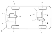
- FIG. 1 shows an electric vehicle EV in which a pair of left and right front wheels 1 are drive wheels driven by a vehicle motor drive device A according to the present invention, and a pair of left and right rear wheels 2 are driven wheels.
- FIG. 2 shows a hybrid vehicle HV in which a pair of left and right front wheels 1 are main drive wheels driven by an engine E, and a pair of left and right rear wheels 2 are auxiliary drive wheels driven by a vehicle motor drive device A according to the present invention. Indicates.
- the hybrid vehicle HV is provided with a transmission T that shifts the rotation of the engine E and a differential gear D that distributes the rotation output from the transmission T to the left and right front wheels 1.
- a vehicle motor drive device A according to the present invention incorporated in the electric vehicle EV and the hybrid vehicle HV will be described below.
- the motor drive device A includes an electric motor 3, a transmission 5 that changes the rotation of the motor shaft 4 of the electric motor 3, and the rotation output from the transmission 5 as shown in FIG. 1. It consists of a differential gear 6 that distributes to a pair of left and right front wheels 1 of a vehicle EV or distributes to a pair of left and right rear wheels 2 of a hybrid vehicle HV shown in FIG.
- the transmission 5 is parallel to the input shaft 7 with an interval between the input shaft 7 to which the rotation of the motor shaft 4 is input, a rotation transmission member 8 that transmits the rotation between the motor shaft 4 and the input shaft 7.
- An output shaft 9 disposed on the input shaft 7, a first speed input gear 10A and a second speed input gear 10B provided on the input shaft 7, and a first speed output gear 11A and a second speed output gear 11B provided on the output shaft 9. .
- the motor shaft 4 is coaxially arranged in series with the input shaft 7 and is rotationally driven by the stator 13 of the electric motor 3 fixed to the housing 12.
- the input shaft 7 is rotatably supported by a pair of opposed bearings 14 incorporated in the housing 12.
- the output shaft 9 is also rotatably supported by a pair of opposed bearings 15 incorporated in the housing 12.
- the first speed input gear 10 ⁇ / b> A and the second speed input gear 10 ⁇ / b> B are arranged at an interval in the axial direction, and are fixed to the input shaft 7 so as to rotate integrally with the input shaft 7 about the input shaft 7.
- the first-speed output gear 11A and the second-speed output gear 11B are also arranged at intervals in the axial direction.
- the first-speed output gear 11A and the second-speed output gear 11B are formed in an annular shape that penetrates the output shaft 9, are supported by the output shaft 9 via bearings 16 (see FIG. 4), and output is centered on the output shaft 9. is rotatable relative to the shaft 9.
- the first speed input gear 10A and the first speed output gear 11A mesh with each other, and rotation is transmitted between the first speed input gear 10A and the first speed output gear 11A.
- the 2nd speed input gear 10B and the 2nd speed output gear 11B are also meshed, and rotation is transmitted between the 2nd speed input gear 10B and the 2nd speed output gear 11B by the meshing.
- the reduction ratio between the second speed input gear 10B and the second speed output gear 11B is smaller than the reduction ratio between the first speed input gear 10A and the first speed output gear 11A.
- a first-speed two-way roller clutch 17A that performs torque transmission and switching between the first-speed output gear 11A and the output shaft 9 is used. Is incorporated. Further, between the second speed output gear 11B and the output shaft 9, there is incorporated a second speed two-way roller clutch 17B that switches between torque transmission and interruption between the second speed output gear 11B and the output shaft 9. .
- the second-speed two-way roller clutch 17B will be described below.
- the same reference numerals are given to the portions corresponding to the two-speed two-way roller clutch 17B, and the description thereof is omitted.
- the 2-speed 2-way roller clutch 17 ⁇ / b> B is provided on the cylindrical surface 20 provided on the inner periphery of the 2-speed output gear 11 ⁇ / b> B and on the outer periphery of the inner ring 19 that is prevented from rotating around the output shaft 9. It consists of a cam surface 18, a roller 21 incorporated between the cam surface 18 and the cylindrical surface 20, a retainer 22 that holds the roller 21, and a switch spring 23.
- the cam surface 18 is a surface that forms a wedge-shaped space that gradually narrows from the center in the circumferential direction toward both ends in the circumferential direction between the cam surface 18 and, for example, faces the cylindrical surface 20 as shown in the figure. It is a flat surface.
- the cage 22 is rotatably supported on the outer periphery of the inner ring 19, and is between an engagement position where the roller 21 is engaged between the cam surface 18 and the cylindrical surface 20 and a neutral position where the engagement of the roller 21 is released. It has become rotatable relative to the output shaft 9.
- the switch spring 23 includes a C-shaped annular portion 23a in which a steel wire is wound in a C shape, and extending portions 23b and 23b that extend radially outward from both ends of the C-shaped annular portion 23a.
- the C-shaped annular portion 23 a is fitted into a circular recess 24 formed on the axial end surface of the inner ring 19.
- the extending portion 23 b passes through a groove 25 formed on the end surface in the axial direction of the inner ring 19 so as to extend from the peripheral edge of the concave portion 24 to the outer diameter side, and the penetrating portion is formed in a notch 26 formed in the cage 22. Has been inserted.
- the groove 25 and the notch 26 are formed to have the same width.
- the extending portion 23b is in contact with the inner surface facing in the circumferential direction of the groove 25 and the inner surface facing in the circumferential direction of the notch 26, and the cage 22 is neutralized by a circumferential force acting on the contact surface. Elastically held in position.
- the position of the groove 25 and the position of the notch 26 are shifted in the circumferential direction, so that the distance between the pair of extending portions 23b, 23b.
- the C-shaped annular portion 23a is elastically deformed in the direction in which the width of the groove is narrowed, and the pair of extending portions 23b, 23b of the switch spring 23 presses the inner surface of the groove 25 and the inner surface of the notch 26 by the elastic restoring force, and is held by the pressing. A force in a direction to return the container 22 to the neutral position is applied.
- the inner ring 19 having the cam surface 18 of the first-speed two-way roller clutch 17A is formed in an annular shape that penetrates the output shaft 9, and is prevented from rotating around the output shaft 9 by spline fitting.
- An inner ring 19 having a cam surface 18 of the two-speed two-way roller clutch 17B is also formed in an annular shape that penetrates the output shaft 9, and is prevented from rotating around the output shaft 9 by spline fitting.
- the first-speed inner ring 19 and the second-speed inner ring 19 are not movable in the axial direction by a locking nut 27 fitted to the outer periphery of the output shaft 9.
- a spacer 28 is incorporated between the inner ring 19 on the first speed side and the inner ring 19 on the second speed side.
- the first-speed two-way roller clutch 17A and the second-speed two-way roller clutch 17B can be selectively engaged by a transmission actuator 29.
- the speed change actuator 29 includes a shift ring 30 that is movably provided in the axial direction between the first speed output gear 11A and the second speed output gear 11B, and the first speed output gear 11A and the shift ring 30.
- the first speed friction plate 31A is provided with a notch 33A that engages with a protrusion 32A formed on the first speed side retainer 22, and the engagement of the protrusion 32A and the notch 33A makes the first speed friction plate 31A one. Rotation is prevented by the fast cage 22. Further, the first speed friction plate 31A can move in the axial direction between a position contacting the side surface of the first speed output gear 11A and a position separating from the position while the protrusion 32A and the notch 33A are engaged. ing.
- the second speed friction plate 31B is also provided with a notch 33B that engages with a protrusion 32B formed on the second speed side retainer 22, and the engagement of the protrusion 32B with the notch 33B makes the second speed friction plate 31B 2 Rotation is prevented by the fast cage 22. Further, the second speed friction plate 31B is supported so as to be movable in the axial direction between a position contacting the side surface of the second speed output gear 11B and a position separating from the position while the protrusion 32B and the notch 33B are engaged. Has been.
- a separation spring 34A is incorporated between the first speed friction plate 31A and the inner ring 19 on the first speed side in a compressed state in the axial direction, and the first speed friction plate 31A is 1 by the elastic restoring force of the separation spring 34A. It is urged in a direction away from the side surface of the high-speed output gear 11A.
- a separation spring 34B is incorporated between the second speed friction plate 31B and the inner ring 19 on the second speed side in a state of being compressed in the axial direction, and the second speed friction plate 31B is caused by the elastic restoring force of the separation spring 34B.
- the second-speed output gear 11B is biased in a direction away from the side surface.
- the shift ring 30 presses the first speed friction plate 31A to contact the side surface of the first speed output gear 11A, and the shift ring 30 presses the second speed friction plate 31B to contact the side surface of the second speed output gear 11B. It is supported so as to be movable in the axial direction between the speed shift position. Further, a shift mechanism 35 that moves the shift ring 30 in the axial direction between the first-speed shift position and the second-speed shift position is provided.
- the shift mechanism 35 includes a shift motor (not shown), a bifurcated shift fork 36 connected to the shift motor via a motion conversion mechanism, and a shift sleeve 38 having an annular groove 37 fitted to the shift fork 36 on the outer periphery.
- the rolling sleeve 39 is assembled to the inner periphery of the shift sleeve 38 so as to be non-movable in the axial direction, and rotatably supports the shift ring 30.
- a motion conversion mechanism feed screw mechanism or the like
- a preload spring 40 that is compressible in the axial direction is incorporated.
- a differential drive gear 41 that transmits the rotation of the output shaft 9 to the differential gear 6 is fixed to the output shaft 9.
- the differential gear 6 includes a differential case 43 that is rotatably supported by a bearing 42, a ring gear 44 that is fixed to the differential case 43 coaxially with the rotational center of the differential case 43, meshed with the differential drive gear 41, and a right angle with the rotational center of the differential case 43.
- the pinion shaft 45 fixed to the differential case 43 in any direction, a pair of pinions 46 rotatably supported by the pinion shaft 45, and a pair of left and right side gears 47 meshing with the pair of pinions 46.
- the left side gear 47 is connected to the shaft end portion of the axle 48 connected to the left wheel
- the right side gear 47 is connected to the shaft end portion of the axle 48 connected to the right wheel.
- the rotation transmitting member 8 includes a disk-shaped first flange member 49, a disk-shaped second flange member 50 disposed to face the first flange member 49, and a second A plurality of support bolts 51 fixed at equal intervals in the circumferential direction on the surface of the flange member 50 facing the first flange member 49, and the second flange member 50 of the first flange member 49 so as to penetrate each support bolt 51.
- a plurality of receiving holes 52 formed on the surface facing each other, and an annular elastic member 53 which is attached to the outer periphery of the support bolt 51 and fits into the receiving hole 52.
- the accommodation holes 52 are formed so that the inner periphery is cylindrical, and each accommodation hole 52 has the same inner diameter.
- the end of the motor shaft 4 is a spline shaft in which a plurality of protrusions extending in the axial direction are formed at equal intervals in the circumferential direction.
- a spline hole 54 is formed in which a plurality of grooves extending in the axial direction are formed at equal intervals in the circumferential direction.
- the spline hole 54 is spline-fitted to the motor shaft 4, and the first flange member 49 is prevented from rotating around the motor shaft 4 by the spline fitting, and when the motor shaft 4 rotates, the first flange member 49 is connected to the motor shaft 4.
- axis 4 and is adapted to rotate integrally.
- a spline hole 55 in which a plurality of grooves extending in the axial direction are formed at equal intervals in the circumferential direction is formed at the shaft end of the input shaft 7.
- a spline shaft 56 is formed in which a plurality of protrusions extending in the axial direction are formed at equal intervals in the circumferential direction.
- the spline shaft 56 is spline-fitted in the spline hole 55, and the second flange member 50 is prevented from rotating around the input shaft 7 by the spline fitting, and when the second flange member 50 rotates, the input shaft 7 The two flange members 50 are rotated together.
- a boss portion 50 a protruding in a columnar shape is formed on the side surface of the second flange member 50 on the input shaft 7 side, and the outer periphery of the boss portion 50 a is rotatably supported by the housing 12 via a bearing 57. Yes.
- the elastic member 53 includes a rubber bush 58, a metal inner sleeve 59 fitted to the inner periphery of the bush 58, and a metal outer sleeve fitted to the outer periphery of the bush 58.
- the bush 58 is a cylindrical rubber molded body, and has an axial end face having a shape in which a cross section along the radial direction is recessed in an arc shape. Further, the inner diameter surface of the bush 58 is vulcanized and bonded to the outer diameter surface of the inner sleeve 59, and the outer diameter surface of the bush 58 is also vulcanized and bonded to the inner diameter surface of the outer sleeve 60.
- the support bolt 51 includes a screw shaft portion 51a having an external thread on the outer periphery, a cylindrical shaft portion 51b having a larger diameter than the screw shaft portion 51a, and a head portion 51c having a larger diameter than the cylindrical shaft portion 51b.
- the screw shaft portion 51a is screwed into the screw hole 61 formed in the second flange member 50.
- the inner sleeve 59 is slightly longer in the axial direction than the cylindrical shaft portion 51 b of the support bolt 51, and when the support bolt 51 is screwed into the screw hole 61, the inner sleeve 59 is the head of the support bolt 51. 51c is pressed against the side surface of the second flange member 50, and the inner sleeve 59 is fixed by the pressing force.
- the elastic member 53 having the above configuration allows relative rotational displacement between the motor shaft 4 and the input shaft 7 by elastic deformation. That is, when the rotation speed of one of the motor shaft 4 and the input shaft 7 changes suddenly while the motor shaft 4 and the input shaft 7 are rotating, the bush 58 of the elastic member 53 is elastically deformed, Due to the elastic deformation, the center of each support bolt 51 and the center of each accommodation hole 52 are eccentric, and a relative rotational displacement occurs between the motor shaft 4 and the input shaft 7.
- the first speed friction plate 31A is separated from the side surface of the first speed output gear 11A, and the second speed friction plate 31B is also separated from the side surface of the second speed output gear 11B.
- the retainer 22 is held in the neutral position by the elastic force of the first-speed switch spring 23, and the second-speed retainer 22 is also held in the neutral position by the elastic force of the second-speed switch spring 23.
- the first-speed two-way roller clutch 17A is disengaged from the roller 21, and the second-speed two-way roller clutch 17B is also disengaged from the roller 21.
- the first speed friction plate 31A becomes 1 by the urging force of the separation spring 34A. Since the friction between the first-speed friction plate 31A and the first-speed output gear 11A is reduced by moving away from the side surface of the high-speed output gear 11A, the first-speed side holding is performed by the elastic force of the first-speed switch spring 23. The device 22 moves from the engagement position to the neutral position, and the engagement of the first-speed two-way roller clutch 17A is released by the movement of the first-speed retainer 22.
- the rotation transmission member 8 is provided with an elastic member 53 that allows relative rotational displacement between the motor shaft 4 and the input shaft 7 by elastic deformation.
- the inertia of the motor shaft 4 indirectly acts on the roller 21 via the elastic member 53, and the deformation of the elastic member 53 causes the motor shaft 4 to move. Since the inertia is buffered, the force for pushing the roller 21 between the cam surface 18 and the cylindrical surface 20 is unlikely to be excessive, and abnormal noise and vibration are unlikely to occur. The same applies when the 2-speed 2-way roller clutch 17B is engaged.
- the vehicle motor drive device A of this embodiment when regenerative braking is performed with the electric motor 3 or when the electric motor 3 accelerates after stopping regenerative braking, torque generated by the electric motor 3 is generated. Since the elastic member 53 is buffered by the deformation of the elastic member 53 and acts on the roller 21, when the pushing direction of the roller 21 between the cam surface 18 and the cylindrical surface 20 is switched between forward and reverse, the roller 21 is moved to the cam surface 18 and the cylindrical surface 20. The force that pushes in between is not excessive, and abnormal noise and vibration are less likely to occur.
- the motor shaft 4 and the input shaft 7 are connected via a plurality of gears, and any one of the gears is used as the rotation transmission member 8.
- the motor shaft 4 and the input shaft 7 are preferably arranged in series on the same axis, and the motor shaft 4 and the input shaft 7 are coupled by the rotation transmission member 8. In this way, the inertia acting on the roller 21 when the first-speed two-way roller clutch 17A or the second-speed two-way roller clutch 17B is engaged can be minimized, and abnormal noise and vibration are effectively prevented. Can be prevented.
- the elastic member 53 for example, it is possible to employ only a rubber bush or a metal spring, but as shown in this embodiment, the rubber bush 58 and the bush 58 It is preferable to employ a metal inner sleeve 59 fitted to the inner periphery and a metal outer sleeve 60 fitted to the outer periphery of the bush 58. In this way, since the outer periphery and inner periphery of the bush 58 are covered with the metal sleeves 59, 60, the rubber bush 58 is less likely to be worn, and the durability required for automobile parts can be ensured. Become. Further, when a metal spring is used as the elastic member 53, the spring may resonate and noise may be generated. However, as shown in this embodiment, when the rubber bush 58 is used, resonance does not occur and abnormal noise is generated. Does not occur.
- the rotation transmission member 8 in which the elastic member 53 is attached to all the support bolts 51 among the plurality of support bolts 51 has been described as an example.
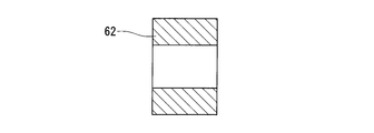
- the elastic members 53 may be attached to the support bolts 51 excluding a part of them, and the rigid rings 62 having an outer diameter smaller than that of the outer sleeve 60 of the elastic members 53 may be attached to the remaining support bolts 51.
- the rigid ring 62 contacts the inner periphery of the accommodation hole 52 and supports a load above a certain level as shown in FIG. The load applied to the member 53 is suppressed, and the life of the elastic member 53 can be improved.
- the rigid ring 62 may be a cylindrical body made of metal in order to ensure its durability.
- the rigid ring 62 is heavier than the elastic member 53, if the rigid rings 62 are arranged at equal intervals in the circumferential direction as shown in FIG. 11, the weight balance of the rotation transmission device can be achieved, and the rotation transmission member 8 vibrations can be prevented.
Landscapes
- Engineering & Computer Science (AREA)
- General Engineering & Computer Science (AREA)
- Mechanical Engineering (AREA)
- Structure Of Transmissions (AREA)
- Hybrid Electric Vehicles (AREA)
- Electric Propulsion And Braking For Vehicles (AREA)
Abstract
変速比の異なる2つの回転伝達経路を切り換えるクラッチとして2ウェイローラクラッチを用いた車両用モータ駆動装置の異音・振動を抑制する。モータ軸(4)と入力軸(7)の間で回転を伝達する回転伝達部材(8)と、入力軸(7)に設けられた1速入力ギヤ(10A)および2速入力ギヤ(10B)と、1速入力ギヤ(10A)および2速入力ギヤ(10B)にそれぞれ噛合する1速出力ギヤ(11A)および2速出力ギヤ(11B)とを有し、1速出力ギヤ(11A)と出力軸(9)との間に1速の2ウェイローラクラッチ(17A)と、2速出力ギヤ(11B)と出力軸(9)との間に2速の2ウェイローラクラッチ(17B)を設け、回転伝達部材(8)は、モータ軸(4)と入力軸(7)の間の相対回転変位を弾性変形により許容する弾性部材(53)を有する構成を車両用モータ駆動装置に採用する。
Description
この発明は、電動モータの回転を変速して車輪へ伝達する車両用モータ駆動装置およびそのモータ駆動装置を搭載した自動車に関する。
電気自動車およびハイブリッド自動車の駆動装置に用いられる車両用モータ駆動装置として、電動モータと、その電動モータの回転を変速する変速機と、その変速機から出力された回転を左右の車輪に分配するディファレンシャルギヤとからなるものが従来から知られている(例えば特許文献1)。
この車両用モータ駆動装置を使用すると、走行条件に応じて変速機の変速比を切り換えることにより、駆動および回生時において、効率の高い回転数およびトルク領域で電動モータを使用することが可能となる。また、適切な変速比とすることで、高速走行時の変速機の回転部材の回転速度が下がり、変速機の動力損失が低減して車両のエネルギ効率を向上させることができる。
このような車両用モータ駆動装置として、例えば特許文献1に記載のものが知られている。特許文献1に記載の車両用モータ駆動装置は、変速比の異なる2つの回転伝達経路にそれぞれ設けられた摩擦クラッチと、その摩擦クラッチを選択的に係合させる変速アクチュエータを有する。
ここで、摩擦クラッチは、回転伝達経路の上流側に接続されたプレッシャプレートと、回転伝達経路の下流側に接続されたクラッチプレートとを軸方向に対向して配置したものであり、プレッシャプレートがクラッチプレートから離反した状態では回転の伝達が遮断され、プレッシャプレートをクラッチプレートに接触させると、その接触面間の摩擦力を介して回転が伝達される。
ところで、本願発明の発明者らは、変速比の異なる2つの回転伝達経路を切り換えるクラッチとして、上記の摩擦クラッチではなく2ウェイローラクラッチを用いた車両用モータ駆動装置を検討し、そのような車両用モータ駆動装置として以下の構成のものを考案した。
電動モータと、その電動モータのモータ軸の回転が入力される入力軸と、入力軸に対して間隔をおいて平行に配置された出力軸と、入力軸に設けられた1速入力ギヤおよび2速入力ギヤと、出力軸に設けられ、1速入力ギヤおよび2速入力ギヤにそれぞれ噛合する1速出力ギヤおよび2速出力ギヤと、出力軸の回転を左右の車輪に分配するディファレンシャルギヤとを有し、
1速出力ギヤと2速出力ギヤは軸受を介して出力軸で回転自在に支持され、
1速出力ギヤと出力軸との間でトルクの伝達と遮断の切換えを行なう1速の2ウェイローラクラッチと、2速出力ギヤと出力軸との間でトルクの伝達と遮断の切換えを行なう2速の2ウェイローラクラッチと、1速の2ウェイローラクラッチと2速の2ウェイローラクラッチとを選択的に係合させる変速アクチュエータを設けた車両用モータ駆動装置。
1速出力ギヤと2速出力ギヤは軸受を介して出力軸で回転自在に支持され、
1速出力ギヤと出力軸との間でトルクの伝達と遮断の切換えを行なう1速の2ウェイローラクラッチと、2速出力ギヤと出力軸との間でトルクの伝達と遮断の切換えを行なう2速の2ウェイローラクラッチと、1速の2ウェイローラクラッチと2速の2ウェイローラクラッチとを選択的に係合させる変速アクチュエータを設けた車両用モータ駆動装置。
ここで、1速の2ウェイローラクラッチは、1速出力ギヤの内周に設けられたカム面と、出力軸の外周に設けられた円筒面と、そのカム面と円筒面の間に組み込まれたローラと、そのローラを保持し、前記カム面と円筒面の間にローラを係合させる係合位置とローラの係合を解除する中立位置との間で出力軸に対して相対回転可能に設けられた1速の保持器とからなる構成のものであり、1速の保持器を係合位置と中立位置の間で周方向に移動させることにより、トルクの伝達と遮断を切り換えることができるようになっている。2速の2ウェイローラクラッチも、1速の2ウェイローラクラッチと同様の構成である。
この車両用モータ駆動装置は、変速アクチュエータを作動させて2速の2ウェイローラクラッチの係合を解除するとともに、1速の2ウェイローラクラッチを係合させることにより、電動モータの回転を1速の変速比で変速して車輪へ伝達することができる。また、1速の2ウェイローラクラッチの係合を解除するとともに、2速の2ウェイローラクラッチを係合させることにより、電動モータの回転を2速の変速比で変速して車輪へ伝達することができる。
しかしながら、上記構成の2ウェイローラクラッチを用いたこの車両用モータ駆動装置においては、変速比を切り換えるときや、電動モータで回生制動するとき等に異音・振動が生じる場合があることが分かった。
そこで、本願発明の発明者らは、この異音・振動の原因を調査したところ、車両用モータ駆動装置のモータ軸と入力軸をスプラインまたはキーで直結していることが原因の1つであることを見出した。
すなわち、摩擦クラッチを係合するときは、プレッシャプレートとクラッチプレートが滑りながら接触して入力側と出力側の回転差が次第にゼロとなるのに対し、2ウェイローラクラッチを係合するときは、カム面と円筒面の間にローラが押し込まれて入力側と出力側の回転差が瞬時にゼロとなる。そのため、車両用モータ駆動装置のモータ軸と入力軸をスプラインまたはキーで直結していると、次変速段の2ウェイローラクラッチが係合するときに、モータ軸と入力軸を合計した大きな慣性がローラに直接的に作用し、その結果、ローラをカム面と円筒面の間に押し込む力が過大となることが原因で異音・振動が生じることが分かった。
また、電動モータで回生制動するときは、カム面と円筒面の間で伝達するトルクの方向が逆になるので、カム面と円筒面の間へのローラの押し込み方向が正逆で切り替わる。このときも、車両用モータ駆動装置のモータ軸と入力軸をスプラインまたはキーで直結していると、電動モータで発生する減速トルクが直接的にローラに作用し、その結果、ローラをカム面と円筒面の間に押し込む力が過大となることが原因で異音・振動が生じることが分かった。
また、電動モータが回生制動を停止した後に加速するときも、カム面と円筒面の間で伝達するトルクの方向が逆になるので、カム面と円筒面の間へのローラの押し込み方向が正逆で切り替わる。このときも、車両用モータ駆動装置のモータ軸と入力軸をスプラインまたはキーで直結していると、電動モータで発生する加速トルクが直接的にローラに作用し、その結果、ローラをカム面と円筒面の間に押し込む力が過大となることが原因で異音・振動が生じることが分かった。
この発明が解決しようとする課題は、変速比の異なる2つの回転伝達経路を切り換えるクラッチとして2ウェイローラクラッチを用いた車両用モータ駆動装置の異音・振動を抑制することである。
上記の課題を解決するため、この発明においては、電動モータと、その電動モータのモータ軸の回転が入力される入力軸と、前記モータ軸と入力軸の間で回転を伝達する回転伝達部材と、前記入力軸に対して間隔をおいて平行に配置された出力軸と、前記入力軸に設けられた第1の入力ギヤおよび第2の入力ギヤと、前記出力軸に設けられ、前記第1の入力ギヤおよび第2の入力ギヤにそれぞれ噛合する第1の出力ギヤおよび第2の出力ギヤと、前記出力軸の回転を左右の車輪に分配するディファレンシャルギヤとを有し、
前記第1の入力ギヤと第2の入力ギヤと入力軸の組と、前記第1の出力ギヤと第2の出力ギヤと出力軸の組とのうち一方を、第1の制御ギヤと第2の制御ギヤとこれらの制御ギヤを軸受を介して回転自在に支持する制御ギヤ支持軸とし、
前記第1の制御ギヤと制御ギヤ支持軸との間でトルクの伝達と遮断の切換えを行なう第1の2ウェイローラクラッチと、前記第2の制御ギヤと制御ギヤ支持軸との間でトルクの伝達と遮断の切換えを行なう第2の2ウェイローラクラッチと、前記第1の2ウェイローラクラッチと第2の2ウェイローラクラッチとを選択的に係合させる変速アクチュエータを設け、
前記第1の2ウェイローラクラッチは、第1の制御ギヤの内周と制御ギヤ支持軸の外周のうち一方に設けられた円筒面と、他方に設けられたカム面と、そのカム面と前記円筒面の間に組み込まれたローラと、そのローラを保持し、前記カム面と円筒面の間にローラを係合させる係合位置とローラの係合を解除する中立位置との間で前記制御ギヤ支持軸に対して相対回転可能に設けられた第1の保持器と、その第1の保持器を前記中立位置に弾性保持する第1のスイッチばねとからなり、
前記第2の2ウェイローラクラッチは、第2の制御ギヤの内周と制御ギヤ支持軸の外周のうち一方に設けられた円筒面と、他方に設けられたカム面と、そのカム面と前記円筒面の間に組み込まれたローラと、そのローラを保持し、前記カム面と円筒面の間にローラを係合させる係合位置とローラの係合を解除する中立位置との間で前記制御ギヤ支持軸に対して相対回転可能に設けられた第2の保持器と、その第2の保持器を前記中立位置に弾性保持する第2のスイッチばねとからなり、
前記回転伝達部材は、前記モータ軸と入力軸の間の相対回転変位を弾性変形により許容する弾性部材を有する構成を車両用モータ駆動装置に採用した。
前記第1の入力ギヤと第2の入力ギヤと入力軸の組と、前記第1の出力ギヤと第2の出力ギヤと出力軸の組とのうち一方を、第1の制御ギヤと第2の制御ギヤとこれらの制御ギヤを軸受を介して回転自在に支持する制御ギヤ支持軸とし、
前記第1の制御ギヤと制御ギヤ支持軸との間でトルクの伝達と遮断の切換えを行なう第1の2ウェイローラクラッチと、前記第2の制御ギヤと制御ギヤ支持軸との間でトルクの伝達と遮断の切換えを行なう第2の2ウェイローラクラッチと、前記第1の2ウェイローラクラッチと第2の2ウェイローラクラッチとを選択的に係合させる変速アクチュエータを設け、
前記第1の2ウェイローラクラッチは、第1の制御ギヤの内周と制御ギヤ支持軸の外周のうち一方に設けられた円筒面と、他方に設けられたカム面と、そのカム面と前記円筒面の間に組み込まれたローラと、そのローラを保持し、前記カム面と円筒面の間にローラを係合させる係合位置とローラの係合を解除する中立位置との間で前記制御ギヤ支持軸に対して相対回転可能に設けられた第1の保持器と、その第1の保持器を前記中立位置に弾性保持する第1のスイッチばねとからなり、
前記第2の2ウェイローラクラッチは、第2の制御ギヤの内周と制御ギヤ支持軸の外周のうち一方に設けられた円筒面と、他方に設けられたカム面と、そのカム面と前記円筒面の間に組み込まれたローラと、そのローラを保持し、前記カム面と円筒面の間にローラを係合させる係合位置とローラの係合を解除する中立位置との間で前記制御ギヤ支持軸に対して相対回転可能に設けられた第2の保持器と、その第2の保持器を前記中立位置に弾性保持する第2のスイッチばねとからなり、
前記回転伝達部材は、前記モータ軸と入力軸の間の相対回転変位を弾性変形により許容する弾性部材を有する構成を車両用モータ駆動装置に採用した。
この構成を採用した車両用モータ駆動装置は、変速アクチュエータを作動させて現変速段の2ウェイローラクラッチの係合を解除するとともに、次変速段の2ウェイローラクラッチを係合させることにより、電動モータの回転を次変速段の変速比で変速して車輪へ伝達することができる。
ここで、次変速段の2ウェイローラクラッチが係合するとき、モータ軸の慣性は回転伝達部材の弾性部材を介して間接的にローラに作用し、弾性部材の変形によってモータ軸の慣性が緩衝されるので、ローラをカム面と円筒面の間に押し込む力が過大となりにくく、異音・振動が生じにくい。
また、電動モータで回生制動するときや、電動モータが回生制動を停止した後に加速するときに、カム面と円筒面の間へのローラの押し込み方向が正逆で切り替わるが、このときも、電動モータで発生するトルクは、弾性部材の変形によって緩衝されてローラに作用するので、ローラをカム面と円筒面の間に押し込む力が過大となりにくく、異音・振動が生じにくい。
前記モータ軸と入力軸を複数のギヤを介して接続し、そのいずれかのギヤを前記回転伝達部材とした構成を採用することも可能であるが、前記モータ軸と入力軸を同軸上に直列に配置し、そのモータ軸と入力軸を前記回転伝達部材で結合すると好ましい。このようにすると、次変速段の2ウェイローラクラッチが係合するときにローラに作用する慣性を最小限に抑えることができ、異音・振動を効果的に防止することができる。
前記回転伝達部材は、前記モータ軸に回り止めされた第1フランジ部材と、その第1フランジ部材に対向して配置され、前記入力軸に回り止めされた第2フランジ部材と、前記第1フランジ部材と第2フランジ部材のうちの一方のフランジ部材に周方向に等間隔に固定された複数の支持ボルトと、その各支持ボルトを貫通させるように他方のフランジ部材に形成された複数の収容孔と、前記支持ボルトの外周で支持され、前記収容孔内に嵌め込まれた環状の前記弾性部材とからなる構成のものを採用することができる。
この場合、前記弾性部材としては、例えばゴム製のブッシュのみからなるものや、金属製のスプリングを採用することも可能であるが、ゴム製のブッシュと、そのブッシュの内周に嵌合する金属製の内スリーブと、前記ブッシュの外周に嵌合する金属製の外スリーブとからなるものを採用すると好ましい。このようにすると、ブッシュの外周と内周が金属製のスリーブで覆われるので、ゴム製のブッシュが摩耗しにくく、自動車部品に要求される耐久性を確保することが可能となる。また、前記弾性部材として金属製のスプリングを用いるとスプリングが共振して異音が生じる可能性があるが、ゴム製のブッシュを用いると共振せず、異音が生じない。
前記複数の支持ボルトのうち全部の支持ボルトに前記弾性部材を装着することも可能であるが、前記複数の支持ボルトのうち一部を除いた支持ボルトに前記弾性部材を装着し、残りの支持ボルトに前記弾性部材よりも外径が小さい剛性リングを装着するようにしてもよい。このようにすると、回転伝達部材に大きい荷重が負荷されたときに、剛性リングが収容孔の内周に接触して一定以上の荷重を支持するので、弾性部材に負荷される荷重が抑えられ、弾性部材の寿命を向上させることができる。
前記剛性リングは、その耐久性を確保するために金属からなるものを採用するとよい。この場合、剛性リングを複数設け、その複数の剛性リングを周方向に等間隔に配置すると、回転伝達装置の重量バランスをとることができ、回転伝達部材の振動を防止することができる。
前記変速アクチュエータとしては、前記第1の保持器に対して回り止めされかつ前記第1の制御ギヤの側面に接触する位置と離反する位置との間で軸方向に移動可能に設けられた第1の摩擦板と、その第1の摩擦板を前記第1の制御ギヤの側面から離反する方向に付勢する第1の離反ばねと、前記第2の保持器に対して回り止めされかつ前記第2の制御ギヤの側面に接触する位置と離反する位置との間で軸方向に移動可能に設けられた第2の摩擦板と、その第2の摩擦板を前記第2の制御ギヤの側面から離反する方向に付勢する第2の離反ばねと、前記第1の摩擦板を押圧して前記第1の制御ギヤの側面に接触させる第1シフト位置と前記第2の摩擦板を押圧して前記第2の制御ギヤの側面に接触させる第2シフト位置との間で軸方向に移動可能に設けられたシフトリングと、そのシフトリングを軸方向に移動させるシフト機構とからなるものを採用することができる。
この構成の変速アクチュエータを採用すると、シフトリングが第1のシフト位置にあるときは、第1の摩擦板が第1の制御ギヤの側面に接触し、その接触面間の摩擦力によって第1の摩擦板が制御ギヤ支持軸に対して相対回転し、この摩擦板に回り止めされた第1の保持器が中立位置から係合位置に移動するので、第1の2ウェイローラクラッチが係合した状態となる。また、このとき、第2の摩擦板は離反ばねの付勢力によって第2の制御ギヤの側面から離反しているので、第2の保持器はスイッチばねの弾性力により中立位置に保持され、第2の2ウェイローラクラッチは係合が解除された状態となる。
そして、シフト機構の作動により、シフトリングを第1のシフト位置から第2のシフト位置に向かって軸方向移動させると、離反ばねの付勢力によって第1の摩擦板が第1の制御ギヤの側面から離反する方向に移動し、第1の摩擦板と第1の制御ギヤの間の摩擦が小さくなるので、スイッチばねの弾性力により第1の保持器が係合位置から中立位置に移動し、この第1の保持器の移動によって第1の2ウェイローラクラッチの係合が解除される。シフトリングが第2のシフト位置に到達すると、第2の摩擦板が第2の制御ギヤの側面に接触し、その接触面間の摩擦力によって第2の摩擦板が制御ギヤ支持軸に対して相対回転し、この摩擦板に回り止めされた第2の保持器が中立位置から係合位置に移動するので、第2の2ウェイローラクラッチが係合した状態となる。
同様にして、シフトリングを第2のシフト位置から第1のシフト位置に軸方向移動させることにより、第2の2ウェイローラクラッチの係合を解除して、第1の2ウェイローラクラッチを係合させることができる。
また、この発明では、上記の車両用モータ駆動装置を用いた電気自動車として、左右一対の前輪と左右一対の後輪のうち少なくとも一方を上記の車両用モータ駆動装置で駆動するようにした電気自動車を提供する。
また、この発明では、上記の車両用モータ駆動装置を用いたハイブリッド自動車として、左右一対の前輪と左右一対の後輪のうち一方をエンジンで駆動し、他方を上記の車両用モータ駆動装置で駆動するようにしたハイブリッド自動車を提供する。
この発明の車両用モータ駆動装置は、次変速段の2ウェイローラクラッチが係合するときに、モータ軸の慣性が回転伝達部材の弾性部材を介して間接的にローラに作用し、このとき生じる弾性部材の変形によってモータ軸の慣性が緩衝されるので、ローラをカム面と円筒面の間に押し込む力が過大となりにくく、異音・振動が生じにくい。
図1は、左右一対の前輪1をこの発明に係る車両用モータ駆動装置Aで駆動される駆動輪とし、左右一対の後輪2を従動輪とした電気自動車EVを示す。
図2は、左右一対の前輪1をエンジンEによって駆動される主駆動輪とし、左右一対の後輪2をこの発明に係る車両用モータ駆動装置Aで駆動される補助駆動輪としたハイブリッド自動車HVを示す。ハイブリッド自動車HVには、エンジンEの回転を変速するトランスミッションTと、トランスミッションTから出力された回転を左右の前輪1に分配するディファレンシャルギヤDとが設けられている。
この電気自動車EVおよびハイブリッド自動車HVに組み込まれたこの発明に係る車両用モータ駆動装置Aについて以下に説明する。
図3に示すように、モータ駆動装置Aは、電動モータ3と、電動モータ3のモータ軸4の回転を変速する変速機5と、その変速機5から出力された回転を図1に示す電気自動車EVの左右一対の前輪1に分配し、または、図2に示すハイブリッド自動車HVの左右一対の後輪2に分配するディファレンシャルギヤ6とからなる。
変速機5は、モータ軸4の回転が入力される入力軸7と、モータ軸4と入力軸7の間で回転を伝達する回転伝達部材8と、入力軸7に対して間隔をおいて平行に配置された出力軸9と、入力軸7に設けられた1速入力ギヤ10Aおよび2速入力ギヤ10Bと、出力軸9に設けられた1速出力ギヤ11Aおよび2速出力ギヤ11Bとを有する。
モータ軸4は、入力軸7と同軸上に直列に配置されており、ハウジング12に固定された電動モータ3のステータ13によって回転駆動される。入力軸7は、ハウジング12内に組込まれた対向一対の軸受14により回転自在に支持されている。出力軸9も、ハウジング12内に組込まれた対向一対の軸受15により回転自在に支持されている。
1速入力ギヤ10Aと2速入力ギヤ10Bは軸方向に間隔をおいて配置され、入力軸7を中心として入力軸7と一体に回転するように入力軸7に固定されている。1速出力ギヤ11Aと2速出力ギヤ11Bも軸方向に間隔をおいて配置されている。1速出力ギヤ11Aと2速出力ギヤ11Bは、出力軸9を貫通させる環状に形成され、軸受16(図4参照)を介して出力軸9で支持されており、出力軸9を中心として出力軸9に対して回転自在となっている。
1速入力ギヤ10Aと1速出力ギヤ11Aは互いに噛合しており、その噛合によって1速入力ギヤ10Aと1速出力ギヤ11Aの間で回転が伝達するようになっている。2速入力ギヤ10Bと2速出力ギヤ11Bも噛合しており、その噛合によって2速入力ギヤ10Bと2速出力ギヤ11Bの間で回転が伝達するようになっている。2速入力ギヤ10Bと2速出力ギヤ11Bの減速比は、1速入力ギヤ10Aと1速出力ギヤ11Aの減速比よりも小さい。
図4に示すように、1速出力ギヤ11Aと出力軸9の間には、1速出力ギヤ11Aと出力軸9の間でトルクの伝達と遮断の切換えを行なう1速の2ウェイローラクラッチ17Aが組込まれている。また、2速出力ギヤ11Bと出力軸9の間には、2速出力ギヤ11Bと出力軸9の間でトルクの伝達と遮断の切換えを行なう2速の2ウェイローラクラッチ17Bが組込まれている。
ここで、1速の2ウェイローラクラッチ17Aと、2速の2ウェイローラクラッチ17Bは、左右対称の同一構成となっているので、2速の2ウェイローラクラッチ17Bを以下に説明し、1速の2ウェイローラクラッチ17Aについては、2速の2ウェイローラクラッチ17Bに対応する部分に同一の符号を付して説明を省略する。
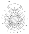
図5に示すように、2速の2ウェイローラクラッチ17Bは、2速出力ギヤ11Bの内周に設けられた円筒面20と、出力軸9に回り止めされた内輪19の外周に設けられたカム面18と、カム面18と円筒面20の間に組み込まれたローラ21と、ローラ21を保持する保持器22と、スイッチばね23とからなる。カム面18は、円筒面20との間で周方向中央から周方向両端に向かって次第に狭くなるくさび形空間を形成するような面であり、例えば、図に示すように円筒面20と対向する平坦面である。
保持器22は、内輪19の外周で回転可能に支持され、カム面18と円筒面20の間にローラ21を係合させる係合位置とローラ21の係合を解除する中立位置との間で出力軸9に対して相対回転可能となっている。
スイッチばね23は、鋼線をC形に巻いたC形環状部23aと、C形環状部23aの両端からそれぞれ径方向外方に延出させた延出部23b,23bとからなる。C形環状部23aは、内輪19の軸方向端面に形成された円形の凹部24に嵌め込まれている。延出部23bは、凹部24の周縁から外径側に延びるように内輪19の軸方向端面に形成された溝25を貫通し、その貫通部分が、保持器22に形成された切欠き26に挿入されている。溝25と切欠き26は同じ幅に形成されている。
延出部23bは、溝25の周方向で対向する内面と、切欠き26の周方向で対向する内面にそれぞれ接触しており、その接触面に作用する周方向の力によって保持器22を中立位置に弾性保持している。
すなわち、保持器22を出力軸9に対して相対回転させて中立位置から移動させると、溝25の位置と切欠き26の位置が周方向にずれるので、一対の延出部23b,23bの間隔が狭まる方向にC形環状部23aが弾性変形し、その弾性復元力によってスイッチばね23の一対の延出部23b,23bが溝25の内面と切欠き26の内面を押圧し、その押圧によって保持器22を中立位置に戻す方向の力が作用するようになっている。
図4に示すように、1速の2ウェイローラクラッチ17Aのカム面18をもつ内輪19は、出力軸9を貫通させる環状に形成され、スプライン嵌合によって出力軸9に回り止めされている。2速の2ウェイローラクラッチ17Bのカム面18をもつ内輪19も、出力軸9を貫通させる環状に形成され、スプライン嵌合によって出力軸9に回り止めされている。また、1速側の内輪19と2速側の内輪19は、出力軸9の外周に嵌合した止めナット27によって軸方向に非可動となっている。1速側の内輪19と2速側の内輪19の間には間座28が組み込まれている。
1速の2ウェイローラクラッチ17Aと2速の2ウェイローラクラッチ17Bは、変速アクチュエータ29により選択的に係合することができるようになっている。
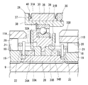
図6に示すように、変速アクチュエータ29は、1速出力ギヤ11Aと2速出力ギヤ11Bの間に軸方向に移動可能に設けられたシフトリング30と、1速出力ギヤ11Aとシフトリング30の間に組み込まれた1速摩擦板31Aと、2速出力ギヤ11Bとシフトリング30の間に組み込まれた2速摩擦板31Bとを有する。
1速摩擦板31Aには、1速側の保持器22に形成された突起32Aに係合する切欠き33Aが設けられ、その突起32Aと切欠き33Aの係合により1速摩擦板31Aが1速側の保持器22に回り止めされている。また、1速摩擦板31Aは、突起32Aと切欠き33Aが係合した状態のままで、1速出力ギヤ11Aの側面に接触する位置と離反する位置との間で軸方向に移動可能となっている。
2速摩擦板31Bにも、2速側の保持器22に形成された突起32Bに係合する切欠き33Bが設けられ、その突起32Bと切欠き33Bの係合により2速摩擦板31Bが2速側の保持器22に回り止めされている。また、2速摩擦板31Bは、突起32Bと切欠き33Bが係合した状態のままで、2速出力ギヤ11Bの側面に接触する位置と離反する位置との間で軸方向に移動可能に支持されている。
1速摩擦板31Aと1速側の内輪19の間には、軸方向に圧縮された状態で離反ばね34Aが組み込まれており、この離反ばね34Aの弾性復元力によって1速摩擦板31Aが1速出力ギヤ11Aの側面から離反する方向に付勢されている。2速摩擦板31Bと2速側の内輪19との間にも、軸方向に圧縮された状態で離反ばね34Bが組み込まれており、この離反ばね34Bの弾性復元力によって2速摩擦板31Bが2速出力ギヤ11Bの側面から離反する方向に付勢されている。
シフトリング30は、1速摩擦板31Aを押圧して1速出力ギヤ11Aの側面に接触させる1速シフト位置と、2速摩擦板31Bを押圧して2速出力ギヤ11Bの側面に接触させる2速シフト位置との間で軸方向に移動可能に支持されている。また、シフトリング30を1速シフト位置と2速シフト位置の間で軸方向に移動させるシフト機構35が設けられている。
シフト機構35は、図示しないシフトモータと、そのシフトモータに運動変換機構を介して接続された二股状のシフトフォーク36と、シフトフォーク36に嵌合する環状溝37を外周にもつシフトスリーブ38と、シフトスリーブ38の内周に軸方向に非可動に組み付けられ、シフトリング30を回転可能に支持する転がり軸受39とからなる。このシフト機構35は、シフトモータを回転させると、シフトモータの回転が運動変換機構(送りねじ機構等)により直線運動に変換されてシフトフォーク36に伝達し、そのシフトフォーク36の直線運動が転がり軸受39を介してシフトリング30に伝達し、シフトリング30が軸方向に移動するようになっている。
シフトフォーク36と環状溝37の間の両側の軸方向隙間には、軸方向に圧縮可能な予圧ばね40が組み込まれている。これにより、シフトリング30で1速摩擦板31Aを押圧して1速摩擦板31Aを1速出力ギヤ11Aの側面に接触させたときに、シフトスリーブ38に対するシフトフォーク36の軸方向の相対位置を調節することによって、シフトリング30が1速摩擦板31Aを押圧する力を調整できるようになっている。また、シフトリング30で2速摩擦板31Bを押圧して2速摩擦板31Bを2速出力ギヤ11Bの側面に接触させたときも、シフトスリーブ38に対するシフトフォーク36の軸方向の相対位置を調節することによって、シフトリング30が2速摩擦板31Bを押圧する力を調整できるようになっている。
図3に示すように、出力軸9には、出力軸9の回転をディファレンシャルギヤ6に伝達するディファレンシャル駆動ギヤ41が固定されている。
ディファレンシャルギヤ6は、軸受42で回転可能に支持されたデフケース43と、デフケース43の回転中心と同軸にデフケース43に固定され、ディファレンシャル駆動ギヤ41に噛合するリングギヤ44と、デフケース43の回転中心と直角な方向にデフケース43に固定されたピニオン軸45と、ピニオン軸45に回転可能に支持された一対のピニオン46と、その一対のピニオン46に噛合する左右一対のサイドギヤ47とからなる。左側のサイドギヤ47には、左側の車輪に接続されたアクスル48の軸端部が接続され、右側のサイドギヤ47には、右側の車輪に接続されたアクスル48の軸端部が接続されている。出力軸9が回転するとき、出力軸9の回転はディファレンシャル駆動ギヤ41を介してデフケース43に伝達され、そのデフケース43の回転がピニオン46とサイドギヤ47を介して左右の車輪に分配される。
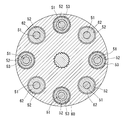
図7、図8に示すように、回転伝達部材8は、円盤状の第1フランジ部材49と、第1フランジ部材49に対向して配置された円盤状の第2フランジ部材50と、第2フランジ部材50の第1フランジ部材49との対向面に周方向に等間隔に固定された複数の支持ボルト51と、各支持ボルト51を貫通させるように第1フランジ部材49の第2フランジ部材50との対向面に形成された複数の収容孔52と、支持ボルト51の外周に装着され、収容孔52内に嵌り込む環状の弾性部材53とからなる。収容孔52は内周が円筒状となるように形成され、各収容孔52は内径が同一である。
図7に示すように、モータ軸4の端部は、軸方向に延びる複数の突条が周方向に等間隔に形成されたスプライン軸とされている。第1フランジ部材49の中心には、軸方向に延びる複数の溝が周方向に等間隔に形成されたスプライン孔54が形成されている。スプライン孔54はモータ軸4にスプライン嵌合しており、そのスプライン嵌合によって第1フランジ部材49がモータ軸4に回り止めされ、モータ軸4が回転したときに、第1フランジ部材49がモータ軸4と一体に回転するようになっている。
入力軸7の軸端には、軸方向に延びる複数の溝が周方向に等間隔に形成されたスプライン孔55が形成されている。第2フランジ部材50の中心には、軸方向に延びる複数の突条が周方向に等間隔に形成されたスプライン軸56が形成されている。スプライン軸56はスプライン孔55にスプライン嵌合しており、そのスプライン嵌合によって第2フランジ部材50が入力軸7に回り止めされ、第2フランジ部材50が回転したときに、入力軸7が第2フランジ部材50と一体に回転するようになっている。また、第2フランジ部材50の入力軸7側の側面には、円柱状に突出するボス部50aが形成され、そのボス部50aの外周が軸受57を介してハウジング12で回転可能に支持されている。
図9に示すように、弾性部材53は、ゴム製のブッシュ58と、そのブッシュ58の内周に嵌合する金属製の内スリーブ59と、ブッシュ58の外周に嵌合する金属製の外スリーブ60とからなる。ブッシュ58は、円筒形状のゴム成形体であり、半径方向に沿った断面が円弧状に凹んだ形状の軸方向端面を有する。また、ブッシュ58の内径面は内スリーブ59の外径面に加硫接着され、ブッシュ58の外径面も外スリーブ60の内径面に加硫接着されている。
図7に示すように、支持ボルト51は、外周に雄ねじを有するねじ軸部51aと、ねじ軸部51aよりも大径の円筒軸部51bと、円筒軸部51bよりも大径の頭部51cとからなり、ねじ軸部51aが、第2フランジ部材50に形成されたねじ孔61にねじ込まれている。
内スリーブ59は、支持ボルト51の円筒軸部51bよりも僅かに軸方向長さが長くなっており、支持ボルト51をねじ孔61にねじ込んだときに、内スリーブ59が支持ボルト51の頭部51cによって第2フランジ部材50の側面に押さえ付けられ、その押圧力によって内スリーブ59が固定されるようになっている。
上記構成の弾性部材53は、モータ軸4と入力軸7の間の相対回転変位を弾性変形により許容する。すなわち、モータ軸4と入力軸7が回転している状態で、モータ軸4と入力軸7のうちのいずれか一方の回転速度が急に変化すると、弾性部材53のブッシュ58が弾性変形し、その弾性変形によって各支持ボルト51の中心と各収容孔52の中心とが偏心し、モータ軸4と入力軸7の間に相対回転変位が生じる。
以下に、車両用モータ駆動装置Aの動作例を説明する。
まず、図6に示すように、1速摩擦板31Aは1速出力ギヤ11Aの側面から離反し、かつ、2速摩擦板31Bも2速出力ギヤ11Bの側面から離反した状態では、1速側の保持器22は1速側のスイッチばね23の弾性力により中立位置に保持され、2速側の保持器22も2速側のスイッチばね23の弾性力により中立位置に保持されるので、図10(a)に示すように1速の2ウェイローラクラッチ17Aはローラ21の係合が解除された状態となり、2速の2ウェイローラクラッチ17Bもローラ21の係合が解除された状態となる。
この状態では、図3に示す電動モータ3のモータ軸4が回転し、入力軸7が回転しても、1速の2ウェイローラクラッチ17Aと2速の2ウェイローラクラッチ17Bによって回転の伝達が遮断されるので、入力軸7の回転は出力軸9に伝達されず、1速出力ギヤ11Aおよび2速出力ギヤ11Bは空転する。
次に、シフト機構35を作動させて、図6に示すシフトリング30を1速出力ギヤ11Aに向けて移動させると、1速摩擦板31Aが1速出力ギヤ11Aの側面に接触し、その接触面間の摩擦力によって1速摩擦板31Aが出力軸9に対して相対回転し、このとき1速摩擦板31Aに回り止めされた1速側の保持器22が中立位置から係合位置に移動するので、図10(b)に示すように、1速の2ウェイローラクラッチ17Aのローラ21が円筒面20とカム面18の間のくさび形空間の狭小部分に押し込まれ、1速の2ウェイローラクラッチ17Aが係合した状態となる。
この状態では、1速出力ギヤ11Aの回転は、1速の2ウェイローラクラッチ17Aを介して出力軸9に伝達され、出力軸9の回転が、ディファレンシャルギヤ6を介してアクスル48に伝達される。その結果、図1に示す電気自動車EVにおいては、駆動輪としての前輪1が回転駆動され、図2に示すハイブリッド自動車HVにおいては補助駆動輪としての後輪2が回転駆動される。
次に、シフト機構35の作動により、図6に示すシフトリング30を1速シフト位置から2速シフト位置に向かって軸方向移動させると、離反ばね34Aの付勢力によって1速摩擦板31Aが1速出力ギヤ11Aの側面から離反する方向に移動し、1速摩擦板31Aと1速出力ギヤ11Aの間の摩擦が小さくなるので、1速側のスイッチばね23の弾性力により1速側の保持器22が係合位置から中立位置に移動し、この1速側の保持器22の移動によって1速の2ウェイローラクラッチ17Aの係合が解除される。
シフトリング30が2速シフト位置に到達すると、2速摩擦板31Bが2速出力ギヤ11Bの側面に接触し、その接触面間の摩擦力によって2速摩擦板31Bが出力軸9に対して相対回転し、この摩擦板に回り止めされた2速側の保持器22が中立位置から係合位置に移動するので、2速の2ウェイローラクラッチ17Bが係合した状態となる。
この状態では、2速出力ギヤ11Bの回転は、2速の2ウェイローラクラッチ17Bを介して出力軸9に伝達され、出力軸9の回転がディファレンシャルギヤ6を介してアクスル48に伝達される。
同様に、シフトリング30を2速シフト位置から1速シフト位置に軸方向移動させることにより、2速の2ウェイローラクラッチ17Bの係合を解除して、1速の2ウェイローラクラッチ17Aを係合させることができる。
ところで、入力軸7が回転している状態で、次変速段として1速の2ウェイローラクラッチ17Aを係合させると、カム面18と円筒面20の間にローラ21が押し込まれて入力側と出力側の回転差が瞬時にゼロとなる。このとき、仮に、車両用モータ駆動装置Aのモータ軸4と入力軸7をスプラインまたはキーで直結していると、次変速段として1速の2ウェイローラクラッチ17Aが係合するときに、モータ軸4と入力軸7を合計した大きな慣性がローラ21に直接的に作用し、その結果、ローラ21をカム面18と円筒面20の間に押し込む力が過大となることが原因で異音・振動が生じるおそれがある。
これに対し、この実施形態の車両用モータ駆動装置Aにおいては、モータ軸4と入力軸7の間の相対回転変位を弾性変形により許容する弾性部材53を回転伝達部材8に設けているので、次変速段として1速の2ウェイローラクラッチ17Aが係合するときに、モータ軸4の慣性が弾性部材53を介して間接的にローラ21に作用し、弾性部材53の変形によってモータ軸4の慣性が緩衝されるので、ローラ21をカム面18と円筒面20の間に押し込む力が過大となりにくく、異音・振動が生じにくい。2速の2ウェイローラクラッチ17Bが係合するときも同様である。
また、1速の2ウェイローラクラッチ17Aを係合させた状態で、電動モータ3による回生制動を開始すると、カム面18と円筒面20の間で伝達するトルクの方向が逆になるので、カム面18と円筒面20の間へのローラ21の押し込み方向が図10(b)に示す正方向から、図10(c)に示す逆方向に切り替わる。このときも、仮に、モータ軸4と入力軸7をスプラインまたはキーで直結していると、電動モータ3で発生する減速トルクが直接的にローラ21に作用し、その結果、ローラ21をカム面18と円筒面20の間に押し込む力が過大となることが原因で異音・振動が生じるおそれがある。
また、電動モータ3が回生制動を停止した後に加速するときも、カム面18と円筒面20の間で伝達するトルクの方向が逆になるので、カム面18と円筒面20の間へのローラ21の押し込み方向が図10(c)に示す逆方向から、図10(b)に示す正方向に切り替わる。このときも、仮に、モータ軸4と入力軸7をスプラインまたはキーで直結していると、電動モータ3で発生する加速トルクが直接的にローラ21に作用し、その結果、ローラ21をカム面18と円筒面20の間に押し込む力が過大となることが原因で異音・振動が生じるおそれがある。
これに対し、この実施形態の車両用モータ駆動装置Aにおいては、電動モータ3で回生制動するときや、電動モータ3が回生制動を停止した後に加速するときに、電動モータ3で発生するトルクが弾性部材53の変形によって緩衝されてローラ21に作用するので、カム面18と円筒面20の間へのローラ21の押し込み方向が正逆で切り替わるときに、ローラ21をカム面18と円筒面20の間に押し込む力が過大となりにくく、異音・振動が生じにくい。
モータ軸4と入力軸7を複数のギヤを介して接続し、そのいずれかのギヤを回転伝達部材8とした構成を採用することも可能であるが、この実施形態で示すように、モータ軸4と入力軸7を同軸上に直列に配置し、そのモータ軸4と入力軸7を回転伝達部材8で結合すると好ましい。このようにすると、1速の2ウェイローラクラッチ17Aまたは2速の2ウェイローラクラッチ17Bが係合するときにローラ21に作用する慣性を最小限に抑えることができ、異音・振動を効果的に防止することができる。
弾性部材53としては、例えばゴム製のブッシュのみからなるものや、金属製のスプリングを採用することも可能であるが、この実施形態で示すように、ゴム製のブッシュ58と、そのブッシュ58の内周に嵌合する金属製の内スリーブ59と、ブッシュ58の外周に嵌合する金属製の外スリーブ60とからなるものを採用すると好ましい。このようにすると、ブッシュ58の外周と内周が金属製のスリーブ59,60で覆われるので、ゴム製のブッシュ58が摩耗しにくく、自動車部品に要求される耐久性を確保することが可能となる。また、弾性部材53として金属製のスプリングを用いるとスプリングが共振して異音が生じる可能性があるが、この実施形態で示すように、ゴム製のブッシュ58を用いると共振せず、異音が生じない。
この実施形態では、複数の支持ボルト51のうち全部の支持ボルト51に弾性部材53を装着した回転伝達部材8を例に挙げて説明したが、図11に示すように、複数の支持ボルト51のうち一部を除いた支持ボルト51に弾性部材53を装着し、残りの支持ボルト51に弾性部材53の外スリーブ60よりも外径が小さい剛性リング62を装着するようにしてもよい。このようにすると、回転伝達部材8に大きい荷重が負荷されたときに、図13に示すように、剛性リング62が収容孔52の内周に接触して一定以上の荷重を支持するので、弾性部材53に負荷される荷重が抑えられ、弾性部材53の寿命を向上させることができる。
図12に示すように、剛性リング62は、その耐久性を確保するために金属からなる円筒体を採用するとよい。この場合、剛性リング62は弾性部材53よりも重いので、図11に示すように、剛性リング62を周方向に等間隔に配置すると、回転伝達装置の重量バランスをとることができ、回転伝達部材8の振動を防止することができる。
1 前輪
2 後輪
3 電動モータ
4 モータ軸
6 ディファレンシャルギヤ
7 入力軸
8 回転伝達部材
9 出力軸
10A 1速入力ギヤ
10B 2速入力ギヤ
11A 1速出力ギヤ
11B 2速出力ギヤ
16 軸受
17A 1速の2ウェイローラクラッチ
17B 2速の2ウェイローラクラッチ
18 カム面
20 円筒面
21 ローラ
22 保持器
23 スイッチばね
29 変速アクチュエータ
30 シフトリング
31A 1速摩擦板
31B 2速摩擦板
34A 1速の離反ばね
34B 2速の離反ばね
35 シフト機構
49 第1フランジ部材
50 第2フランジ部材
51 支持ボルト
52 収容孔
53 弾性部材
58 ブッシュ
59 内スリーブ
60 外スリーブ
62 剛性リング
E エンジン
2 後輪
3 電動モータ
4 モータ軸
6 ディファレンシャルギヤ
7 入力軸
8 回転伝達部材
9 出力軸
10A 1速入力ギヤ
10B 2速入力ギヤ
11A 1速出力ギヤ
11B 2速出力ギヤ
16 軸受
17A 1速の2ウェイローラクラッチ
17B 2速の2ウェイローラクラッチ
18 カム面
20 円筒面
21 ローラ
22 保持器
23 スイッチばね
29 変速アクチュエータ
30 シフトリング
31A 1速摩擦板
31B 2速摩擦板
34A 1速の離反ばね
34B 2速の離反ばね
35 シフト機構
49 第1フランジ部材
50 第2フランジ部材
51 支持ボルト
52 収容孔
53 弾性部材
58 ブッシュ
59 内スリーブ
60 外スリーブ
62 剛性リング
E エンジン
Claims (10)
- 電動モータ(3)と、
その電動モータ(3)のモータ軸(4)の回転が入力される入力軸(7)と、
前記モータ軸(4)と入力軸(7)の間で回転を伝達する回転伝達部材(8)と、
前記入力軸(7)に対して間隔をおいて平行に配置された出力軸(9)と、
前記入力軸(7)に設けられた第1の入力ギヤ(10A)および第2の入力ギヤ(10B)と、
前記出力軸(9)に設けられ、前記第1の入力ギヤ(10A)および第2の入力ギヤ(10B)にそれぞれ噛合する第1の出力ギヤ(11A)および第2の出力ギヤ(11B)と、
前記出力軸(9)の回転を左右の車輪に分配するディファレンシャルギヤ(6)とを有し、
前記第1の入力ギヤ(10A)と第2の入力ギヤ(10B)と入力軸(7)の組と、前記第1の出力ギヤ(11A)と第2の出力ギヤ(11B)と出力軸(9)の組とのうち一方を、第1の制御ギヤ(11A)と第2の制御ギヤ(11B)とこれらの制御ギヤ(11A,11B)を軸受(16)を介して回転自在に支持する制御ギヤ支持軸(9)とし、
前記第1の制御ギヤ(11A)と制御ギヤ支持軸(9)との間でトルクの伝達と遮断の切換えを行なう第1の2ウェイローラクラッチ(17A)と、前記第2の制御ギヤ(11B)と制御ギヤ支持軸(9)との間でトルクの伝達と遮断の切換えを行なう第2の2ウェイローラクラッチ(17B)と、前記第1の2ウェイローラクラッチ(17A)と第2の2ウェイローラクラッチ(17B)とを選択的に係合させる変速アクチュエータ(29)を設け、
前記第1の2ウェイローラクラッチ(17A)は、第1の制御ギヤ(11A)の内周と制御ギヤ支持軸(9)の外周のうち一方に設けられた円筒面(20)と、他方に設けられたカム面(18)と、そのカム面(18)と前記円筒面(20)の間に組み込まれたローラ(21)と、そのローラ(21)を保持し、前記カム面(18)と円筒面(20)の間にローラ(21)を係合させる係合位置とローラ(21)の係合を解除する中立位置との間で前記制御ギヤ支持軸(9)に対して相対回転可能に設けられた第1の保持器(22)と、その第1の保持器(22)を前記中立位置に弾性保持する第1のスイッチばね(23)とからなり、
前記第2の2ウェイローラクラッチ(17B)は、第2の制御ギヤ(11B)の内周と制御ギヤ支持軸(9)の外周のうち一方に設けられた円筒面(20)と、他方に設けられたカム面(18)と、そのカム面(18)と前記円筒面(20)の間に組み込まれたローラ(21)と、そのローラ(21)を保持し、前記カム面(18)と円筒面(20)の間にローラ(21)を係合させる係合位置とローラの係合を解除する中立位置との間で前記制御ギヤ支持軸(9)に対して相対回転可能に設けられた第2の保持器(22)と、その第2の保持器(22)を前記中立位置に弾性保持する第2のスイッチばね(23)とからなり、
前記回転伝達部材(8)は、前記モータ軸(4)と入力軸(7)の間の相対回転変位を弾性変形により許容する弾性部材(53)を有する車両用モータ駆動装置。 - 前記モータ軸(4)と入力軸(7)を同軸上に直列に配置し、そのモータ軸(4)と入力軸(7)を前記回転伝達部材(8)で結合した請求項1に記載の車両用モータ駆動装置。
- 前記回転伝達部材(8)が、
前記モータ軸(4)に回り止めされた第1フランジ部材(49)と、
その第1フランジ部材(49)に対向して配置され、前記入力軸(7)に回り止めされた第2フランジ部材(50)と、
前記第1フランジ部材(49)と第2フランジ部材(50)のうちの一方のフランジ部材(50)に周方向に等間隔に固定された複数の支持ボルト(51)と、
その各支持ボルト(51)を貫通させるように他方のフランジ部材(49)に形成された複数の収容孔(52)と、
前記支持ボルト(51)の外周に装着され、前記収容孔(52)内に嵌り込む環状の前記弾性部材(53)とからなる請求項2に記載の車両用モータ駆動装置。 - 前記弾性部材(53)が、ゴム製のブッシュ(58)と、そのブッシュ(58)の内周に嵌合する金属製の内スリーブ(59)と、前記ブッシュ(58)の外周に嵌合する金属製の外スリーブ(60)とからなる請求項3に記載の車両用モータ駆動装置。
- 前記複数の支持ボルト(51)のうち一部を除いた支持ボルト(51)に前記弾性部材(53)を装着し、残りの支持ボルト(51)に前記弾性部材(53)よりも外径が小さい剛性リング(62)を装着した請求項3または4に記載の車両用モータ駆動装置。
- 前記剛性リング(62)が金属からなる請求項5に記載の車両用モータ駆動装置。
- 前記剛性リング(62)を複数設け、その複数の剛性リング(62)を周方向に等間隔に配置した請求項6に記載の車両用モータ駆動装置。
- 前記変速アクチュエータ(29)は、前記第1の保持器(22)に対して回り止めされかつ前記第1の制御ギヤ(11A)の側面に接触する位置と離反する位置との間で軸方向に移動可能に設けられた第1の摩擦板(31A)と、その第1の摩擦板(31A)を前記第1の制御ギヤ(11A)の側面から離反する方向に付勢する第1の離反ばね(34A)と、前記第2の保持器(22)に対して回り止めされかつ前記第2の制御ギヤ(11B)の側面に接触する位置と離反する位置との間で軸方向に移動可能に設けられた第2の摩擦板(31B)と、その第2の摩擦板(31B)を前記第2の制御ギヤ(11B)の側面から離反する方向に付勢する第2の離反ばね(34B)と、前記第1の摩擦板(31A)を押圧して前記第1の制御ギヤ(11A)の側面に接触させる第1シフト位置と前記第2の摩擦板(31B)を押圧して前記第2の制御ギヤ(11B)の側面に接触させる第2シフト位置との間で軸方向に移動可能に設けられたシフトリング(30)と、そのシフトリング(30)を軸方向に移動させるシフト機構(35)とからなる請求項7に記載の車両用モータ駆動装置。
- 左右一対の前輪(1)と左右一対の後輪(2)のうち少なくとも一方を請求項1から8のいずれかに記載の車両用モータ駆動装置で駆動するようにした電気自動車。
- 左右一対の前輪(1)と左右一対の後輪(2)のうち一方をエンジン(E)で駆動し、他方を請求項1から8のいずれかに記載の車両用モータ駆動装置で駆動するようにしたハイブリッド自動車。
Applications Claiming Priority (2)
| Application Number | Priority Date | Filing Date | Title |
|---|---|---|---|
| JP2011060144A JP2012193823A (ja) | 2011-03-18 | 2011-03-18 | 車両用モータ駆動装置および自動車 |
| JP2011-060144 | 2011-03-18 |
Publications (1)
| Publication Number | Publication Date |
|---|---|
| WO2012128020A1 true WO2012128020A1 (ja) | 2012-09-27 |
Family
ID=46879177
Family Applications (1)
| Application Number | Title | Priority Date | Filing Date |
|---|---|---|---|
| PCT/JP2012/055522 Ceased WO2012128020A1 (ja) | 2011-03-18 | 2012-03-05 | 車両用モータ駆動装置および自動車 |
Country Status (2)
| Country | Link |
|---|---|
| JP (1) | JP2012193823A (ja) |
| WO (1) | WO2012128020A1 (ja) |
Cited By (3)
| Publication number | Priority date | Publication date | Assignee | Title |
|---|---|---|---|---|
| CN103104660A (zh) * | 2012-09-29 | 2013-05-15 | 刘培生 | 一种机械动力变速器 |
| US20130296129A1 (en) * | 2011-01-07 | 2013-11-07 | Yoshinori Itakura | Motor drive assembly for a vehicle and a motor vehicle |
| CN116867983A (zh) * | 2021-03-10 | 2023-10-10 | 株式会社F.C.C. | 离合器装置及其使用的离合器外壳 |
Families Citing this family (1)
| Publication number | Priority date | Publication date | Assignee | Title |
|---|---|---|---|---|
| CN105041987A (zh) * | 2015-06-29 | 2015-11-11 | 无锡市神力齿轮冷挤有限公司 | 纯电动汽车用减速器 |
Citations (4)
| Publication number | Priority date | Publication date | Assignee | Title |
|---|---|---|---|---|
| JPS5951239U (ja) * | 1982-09-29 | 1984-04-04 | 株式会社小松製作所 | ダンパ装置 |
| JPH07317848A (ja) * | 1994-05-27 | 1995-12-08 | Honda Motor Co Ltd | 電動車両用トランスミッション |
| WO2010150851A1 (ja) * | 2009-06-24 | 2010-12-29 | 株式会社ユニバンス | 車両用制御装置 |
| WO2011030670A1 (ja) * | 2009-09-08 | 2011-03-17 | Ntn株式会社 | 車両用モータ駆動装置および自動車 |
-
2011
- 2011-03-18 JP JP2011060144A patent/JP2012193823A/ja not_active Withdrawn
-
2012
- 2012-03-05 WO PCT/JP2012/055522 patent/WO2012128020A1/ja not_active Ceased
Patent Citations (4)
| Publication number | Priority date | Publication date | Assignee | Title |
|---|---|---|---|---|
| JPS5951239U (ja) * | 1982-09-29 | 1984-04-04 | 株式会社小松製作所 | ダンパ装置 |
| JPH07317848A (ja) * | 1994-05-27 | 1995-12-08 | Honda Motor Co Ltd | 電動車両用トランスミッション |
| WO2010150851A1 (ja) * | 2009-06-24 | 2010-12-29 | 株式会社ユニバンス | 車両用制御装置 |
| WO2011030670A1 (ja) * | 2009-09-08 | 2011-03-17 | Ntn株式会社 | 車両用モータ駆動装置および自動車 |
Cited By (5)
| Publication number | Priority date | Publication date | Assignee | Title |
|---|---|---|---|---|
| US20130296129A1 (en) * | 2011-01-07 | 2013-11-07 | Yoshinori Itakura | Motor drive assembly for a vehicle and a motor vehicle |
| US9033851B2 (en) * | 2011-01-07 | 2015-05-19 | Ntn Corporation | Motor drive assembly for a vehicle and a motor vehicle |
| CN103104660A (zh) * | 2012-09-29 | 2013-05-15 | 刘培生 | 一种机械动力变速器 |
| CN116867983A (zh) * | 2021-03-10 | 2023-10-10 | 株式会社F.C.C. | 离合器装置及其使用的离合器外壳 |
| CN116867983B (zh) * | 2021-03-10 | 2024-07-12 | 株式会社F.C.C. | 离合器装置及其使用的离合器外壳 |
Also Published As
| Publication number | Publication date |
|---|---|
| JP2012193823A (ja) | 2012-10-11 |
Similar Documents
| Publication | Publication Date | Title |
|---|---|---|
| JP2012219852A (ja) | 車両用モータ駆動装置および自動車 | |
| JP5465614B2 (ja) | 車両用モータ駆動装置および自動車 | |
| US9033851B2 (en) | Motor drive assembly for a vehicle and a motor vehicle | |
| US11493128B2 (en) | Motive power transmission route switching device and two-speed transmission | |
| US9234566B2 (en) | Transmission | |
| WO2012137812A1 (ja) | 車両用モータ駆動装置および自動車 | |
| US11982340B2 (en) | Two-speed transmission | |
| US8850928B2 (en) | Power takeoff unit for automobile | |
| WO2010143740A1 (ja) | 動力伝達装置 | |
| WO2011030689A1 (ja) | 電気自動車 | |
| JP5474456B2 (ja) | 車両用モータ駆動装置および自動車 | |
| JP2012193823A (ja) | 車両用モータ駆動装置および自動車 | |
| WO2012165146A1 (ja) | 車両用モータ駆動装置の変速制御方法および自動車の変速制御方法 | |
| JP2013130266A (ja) | 車両用モータ駆動装置 | |
| WO2012128243A1 (ja) | 車両用モータ駆動装置および自動車 | |
| US20250305546A1 (en) | Two-speed transmission | |
| JP2008045601A (ja) | 動力伝達装置 | |
| JP2013108613A (ja) | クラッチ及び四輪駆動車 | |
| JP4194287B2 (ja) | ギアプレート式アクチュエータ及びこれを用いた動力断続装置及びデファレンシャル装置 | |
| JP3477506B2 (ja) | オンオフ式トルクリミッタ | |
| JP4848978B2 (ja) | ベルト式無段変速機 | |
| CN223411326U (zh) | 一种制动钳传动机构及车辆 | |
| US20260061822A1 (en) | Power transmission device | |
| JP2020128771A (ja) | 駆動力伝達装置及び四輪駆動車 | |
| JP2013024379A (ja) | 差動装置 |
Legal Events
| Date | Code | Title | Description |
|---|---|---|---|
| 121 | Ep: the epo has been informed by wipo that ep was designated in this application |
Ref document number: 12760175 Country of ref document: EP Kind code of ref document: A1 |
|
| NENP | Non-entry into the national phase |
Ref country code: DE |
|
| 122 | Ep: pct application non-entry in european phase |
Ref document number: 12760175 Country of ref document: EP Kind code of ref document: A1 |