WO2012128003A1 - サイクロイド減速機及びインホイールモータ駆動装置 - Google Patents
サイクロイド減速機及びインホイールモータ駆動装置 Download PDFInfo
- Publication number
- WO2012128003A1 WO2012128003A1 PCT/JP2012/055034 JP2012055034W WO2012128003A1 WO 2012128003 A1 WO2012128003 A1 WO 2012128003A1 JP 2012055034 W JP2012055034 W JP 2012055034W WO 2012128003 A1 WO2012128003 A1 WO 2012128003A1
- Authority
- WO
- WIPO (PCT)
- Prior art keywords
- housing
- outer pin
- cycloid
- pin
- flange portion
- Prior art date
- Legal status (The legal status is an assumption and is not a legal conclusion. Google has not performed a legal analysis and makes no representation as to the accuracy of the status listed.)
- Ceased
Links
Images

Classifications
-
- F—MECHANICAL ENGINEERING; LIGHTING; HEATING; WEAPONS; BLASTING
- F16—ENGINEERING ELEMENTS AND UNITS; GENERAL MEASURES FOR PRODUCING AND MAINTAINING EFFECTIVE FUNCTIONING OF MACHINES OR INSTALLATIONS; THERMAL INSULATION IN GENERAL
- F16H—GEARING
- F16H1/00—Toothed gearings for conveying rotary motion
- F16H1/28—Toothed gearings for conveying rotary motion with gears having orbital motion
- F16H1/32—Toothed gearings for conveying rotary motion with gears having orbital motion in which the central axis of the gearing lies inside the periphery of an orbital gear
-
- B—PERFORMING OPERATIONS; TRANSPORTING
- B60—VEHICLES IN GENERAL
- B60K—ARRANGEMENT OR MOUNTING OF PROPULSION UNITS OR OF TRANSMISSIONS IN VEHICLES; ARRANGEMENT OR MOUNTING OF PLURAL DIVERSE PRIME-MOVERS IN VEHICLES; AUXILIARY DRIVES FOR VEHICLES; INSTRUMENTATION OR DASHBOARDS FOR VEHICLES; ARRANGEMENTS IN CONNECTION WITH COOLING, AIR INTAKE, GAS EXHAUST OR FUEL SUPPLY OF PROPULSION UNITS IN VEHICLES
- B60K17/00—Arrangement or mounting of transmissions in vehicles
- B60K17/04—Arrangement or mounting of transmissions in vehicles characterised by arrangement, location or kind of gearing
- B60K17/043—Transmission unit disposed in on near the vehicle wheel, or between the differential gear unit and the wheel
- B60K17/046—Transmission unit disposed in on near the vehicle wheel, or between the differential gear unit and the wheel with planetary gearing having orbital motion
-
- B—PERFORMING OPERATIONS; TRANSPORTING
- B60—VEHICLES IN GENERAL
- B60K—ARRANGEMENT OR MOUNTING OF PROPULSION UNITS OR OF TRANSMISSIONS IN VEHICLES; ARRANGEMENT OR MOUNTING OF PLURAL DIVERSE PRIME-MOVERS IN VEHICLES; AUXILIARY DRIVES FOR VEHICLES; INSTRUMENTATION OR DASHBOARDS FOR VEHICLES; ARRANGEMENTS IN CONNECTION WITH COOLING, AIR INTAKE, GAS EXHAUST OR FUEL SUPPLY OF PROPULSION UNITS IN VEHICLES
- B60K7/00—Disposition of motor in, or adjacent to, traction wheel
- B60K7/0007—Disposition of motor in, or adjacent to, traction wheel the motor being electric
-
- B—PERFORMING OPERATIONS; TRANSPORTING
- B60—VEHICLES IN GENERAL
- B60K—ARRANGEMENT OR MOUNTING OF PROPULSION UNITS OR OF TRANSMISSIONS IN VEHICLES; ARRANGEMENT OR MOUNTING OF PLURAL DIVERSE PRIME-MOVERS IN VEHICLES; AUXILIARY DRIVES FOR VEHICLES; INSTRUMENTATION OR DASHBOARDS FOR VEHICLES; ARRANGEMENTS IN CONNECTION WITH COOLING, AIR INTAKE, GAS EXHAUST OR FUEL SUPPLY OF PROPULSION UNITS IN VEHICLES
- B60K7/00—Disposition of motor in, or adjacent to, traction wheel
- B60K2007/0038—Disposition of motor in, or adjacent to, traction wheel the motor moving together with the wheel axle
-
- B—PERFORMING OPERATIONS; TRANSPORTING
- B60—VEHICLES IN GENERAL
- B60K—ARRANGEMENT OR MOUNTING OF PROPULSION UNITS OR OF TRANSMISSIONS IN VEHICLES; ARRANGEMENT OR MOUNTING OF PLURAL DIVERSE PRIME-MOVERS IN VEHICLES; AUXILIARY DRIVES FOR VEHICLES; INSTRUMENTATION OR DASHBOARDS FOR VEHICLES; ARRANGEMENTS IN CONNECTION WITH COOLING, AIR INTAKE, GAS EXHAUST OR FUEL SUPPLY OF PROPULSION UNITS IN VEHICLES
- B60K7/00—Disposition of motor in, or adjacent to, traction wheel
- B60K2007/0092—Disposition of motor in, or adjacent to, traction wheel the motor axle being coaxial to the wheel axle
-
- F—MECHANICAL ENGINEERING; LIGHTING; HEATING; WEAPONS; BLASTING
- F16—ENGINEERING ELEMENTS AND UNITS; GENERAL MEASURES FOR PRODUCING AND MAINTAINING EFFECTIVE FUNCTIONING OF MACHINES OR INSTALLATIONS; THERMAL INSULATION IN GENERAL
- F16H—GEARING
- F16H1/00—Toothed gearings for conveying rotary motion
- F16H1/28—Toothed gearings for conveying rotary motion with gears having orbital motion
- F16H1/32—Toothed gearings for conveying rotary motion with gears having orbital motion in which the central axis of the gearing lies inside the periphery of an orbital gear
- F16H2001/325—Toothed gearings for conveying rotary motion with gears having orbital motion in which the central axis of the gearing lies inside the periphery of an orbital gear comprising a carrier with pins guiding at least one orbital gear with circular holes
Definitions
- the present invention relates to a cycloid reduction gear and an in-wheel motor drive device using the same, and more particularly to a support bearing for an outer pin in a cycloid reduction gear.
- the cycloid reducer generally includes an eccentric cam provided on an input shaft, a curved plate that is rotatably fitted to the outer peripheral surface of the eccentric cam and has an arc gear on the outer peripheral portion, and the outer side in the radial direction of the curved plate.
- An annular outer pin housing provided on the inner peripheral surface of the housing concentrically with the input shaft, an outer pin held by the outer pin housing and engaged with the arc gear, and the rotational movement of the curved plate as an output member And a motion conversion mechanism for transmission. Both end portions of the outer pin are supported by the outer pin housing via a rolling bearing (Patent Document 1).
- the cycloid reducer is compact but has the advantage of obtaining a high reduction ratio.
- the reduction ratio is n
- the number of external pins is (n-1).
- the needle roller bearing 111 includes a needle roller 112, a cage 113, and an outer ring 114 as shown in FIG.
- the needle roller bearing 111 is interposed between both ends of the outer pin 118 and the hole 117 of the outer pin housing 115 that supports the outer pin 118.
- the outer pin housing 115 is fitted and fixed to the inner surface of the reduction gear housing 119.
- the needle roller bearing 111 reduces the friction in the radial direction of the outer pin 118, and a steel ball 120 is interposed between the end surface of the outer pin 118 and the speed reducer housing 119. Friction can be reduced.
- a thrust plate 121 may be embedded in the contact surface of the steel ball 120. Further, the flange portion of the clip 122 engaged with the outer pin housing 115 is engaged with the inner end surface of the outer ring 114, so that the outer ring 114 is prevented from coming off.
- the cage 113 of the needle roller bearing 111 is prevented from moving by the wall of the speed reducer housing 119 to the outside in the axial direction, but is obstructed to the inside in the opposite direction. Therefore, the cage 113 may come out together with the needle rollers 112 when subjected to vibration, impact, or the like.
- the provision of the stepped portion 123 on the outer pin 118 increases the manufacturing process and increases the inspection time for managing the outer diameter, which increases the cost.
- the present invention is accompanied by an increase in cost and an increase in the size of the housing in the cycloid speed reducer and the in-wheel motor drive device using the same, which prevents the retainer of the needle roller bearing that supports the outer pin from coming out. It is a problem to realize without.
- the present invention includes an eccentric cam provided on an input shaft, a curved plate that is rotatably fitted to an outer peripheral surface of the eccentric cam and has an arc gear on the outer peripheral portion, and the arc gear.
- the retainer of the needle roller bearing is provided with an engaging portion, and the engaging portion is engaged in the axial direction with a fixing member that is radially adjacent to the retainer and fixed in the axial direction.
- the “engagement portion” of the cage specifically refers to an engagement collar portion formed by bending the outer edge of the cage toward the inner diameter side or the outer diameter side.
- the “fixing member radially adjacent to the cage and fixed in the axial direction” specifically refers to an outer pin or an outer ring.
- the engaging portion is provided in the cage of the needle roller bearing that supports the outer pin, and the engaging portion is used as a fixing member.
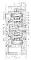
- FIG. 1 is a cross-sectional view of an in-wheel motor drive device.
- FIG. 2 is an enlarged cross-sectional view of the deceleration portion same as above.
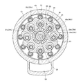
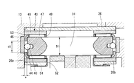
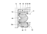
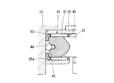
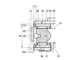
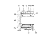
- 3 is a cross-sectional view taken along line X1-X1 of FIG. 4 is an enlarged cross-sectional view of the outer pin support portion of FIG. 5 is a partially enlarged cross-sectional view of another example 1 of the outer pin support portion of FIG. 6 is a partially enlarged cross-sectional view of another example 2 of the outer pin support portion of FIG. 7 is a partially enlarged cross-sectional view of another example 3 of the outer pin support portion of FIG. 8 is a partially enlarged cross-sectional view of another example 4 of the outer pin support portion of FIG.
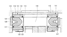
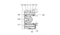
- FIG. 9 is an enlarged cross-sectional view of a conventional outer pin support portion.
- FIG. 10 is a partially enlarged cross-sectional view of another example of a conventional outer pin support portion.
- the in-wheel motor drive device 11 includes a motor unit A that generates a driving force, a deceleration unit B that decelerates and outputs the rotation of the motor unit A, and a deceleration unit.
- a wheel hub bearing portion C that transmits the output of the portion B to the wheels is provided.
- the motor part A is incorporated in the motor housing 12, and the reduction part B is incorporated in the reduction part housing 13.
- a speed reduction unit housing 13 is connected and fixed to the front end of the motor housing 12 by a bolt 14.
- the motor part A includes a stator 15 fixed to the motor housing 12 and a rotor 17 integrated with the motor shaft 16, and the stator 15 and the rotor 17 constitute a radial gap motor opposed to each other in the radial direction.
- the rotor 17 is fixed to the flange 19 of the motor shaft 16 by bolts 18.
- the motor shaft 16 is rotatably supported by the motor housing 12 via rolling bearings 21a and 21b at both front and rear ends.
- the motor shaft 16 is provided with an internal passage 22, and the input shaft 23 of the speed reduction portion B is connected to the front end of the internal passage 22.
- the input shaft 23 is also provided with an internal passage 25, and both the internal passages 22 and 25 communicate with each other.
- the reduction part B is comprised by the cycloid reduction gear which is the object of this invention.
- the speed reduction part B includes an annular outer pin housing 26 fitted and fixed concentrically with the input shaft 23 on the inner diameter surface of the speed reduction part housing 13 (see FIGS. 1 and 2), and each member constituting the speed reduction part B Is provided on the inner diameter side of the outer pin housing 26.
- a pair of eccentric cams 27a and 27b provided adjacent to each other in the axial direction on the input shaft 23, and the eccentric cams 27a and 27b via cylindrical roller bearings 28a and 28b.
- Rotating curved plates 29a and 29b, a plurality of outer pins 31 (see FIG. 3) fixed at equal intervals along the inner diameter surface of the outer pin housing 26, and the rotational motion of the curved plates 29a and 29b are output members.
- There is a motion conversion mechanism 20 constituted by an inner pin 34 that transmits to 32 and its through hole 39, counterweights 33a, 33b attached to the input shaft 23 adjacent to the outer side in the axial direction of the eccentric cams 27a, 27b, etc. .
- the eccentric cams 27a and 27b are provided with a 180 ° phase change so as to cancel out centrifugal forces due to the eccentric motion.
- the output member 32 has a flange portion 32a and a shaft portion 32b (see FIG. 2).
- One end portions of a plurality of inner pins 34 are inserted into and fixed to the flange portion 32a at equal intervals on the circumference around the rotation axis of the output member 32.
- the shaft portion 32b is fitted and fixed to the inner diameter surface of the wheel hub 35, and transmits the output of the speed reduction portion B to the wheel.
- a rolling bearing 36 is interposed between the inner diameter surface of the flange portion 32a of the output member 32 and the input shaft 23, so that the input shaft 23 and the output member 32 are held concentrically and are relatively rotatable.
- the other end portion of the inner pin 34 is inserted and supported by a flange portion 37a of the stabilizer 37 (see FIG. 2).
- the stabilizer 37 has a cylindrical portion 37b provided on the inner diameter of the flange portion 37a, and the cylindrical portion 37b has a front end portion (end portion on the speed reduction portion B side) outer diameter of the motor shaft 16 through a needle roller bearing 38.
- the surface is rotatably fitted.
- the curved plates 29a and 29b have an arc gear 30 formed of a trochoidal curve such as epitrochoid on the outer peripheral portion, and a plurality of penetrating holes penetrating from one end surface to the other end surface in the axial direction.
- a hole 39 is provided.
- the through holes 39 are provided in the same number and at the same intervals as the inner pins 34 on the circumference around the rotation axis of the curved plates 29a and 29b, and the inner pins 34 are provided in the respective through holes 39. It is inserted with a margin in the radial direction (twice the amount of eccentricity).
- the curved plates 29a and 29b are rotatably supported by the eccentric cams 27a and 27b via cylindrical roller bearings 28a and 28b, respectively.
- the phases of the curved plates 29a and 29b are also shifted by 180 ° in the same direction as the eccentric cams 27a and 27b.
- counterweights 33a and 33b are provided adjacent to the outer sides in the axial direction of the eccentric cams 27a and 27b. These counterweights 33a and 33b are attached to the eccentric cams 27a and 27b in an eccentric state in which the phase is changed by 180 °.
- the outer pin housing 26 is formed in an annular shape (see FIG. 3), and is provided with holes 26a, 26b corresponding to the number of outer pins 31, respectively, at regular intervals in the circumferential direction. Both end portions of the outer pin 31 are inserted into the holes 26 a and 26 b and supported by the speed reduction unit housing 13 through the needle roller bearings 43.
- the number of the outer pins 31 is one more than the number of teeth of the arcuate gears 30 of the curved plates 29a and 29b, and a plurality of outer pins 31 are simultaneously engaged with the arcuate gears 30.
- the above-described motion conversion mechanism 20 includes a plurality of inner pins 34 fixed to the output member 32 and through holes 39 provided in the curved plates 29a and 29b.
- the inner diameter dimension of the through-hole 39 is only twice the eccentric amount of the eccentric cams 27a and 27b from the outer diameter dimension of the inner pin 34 (referred to as "the maximum outer diameter including the needle roller bearings 46a and 46b"). It is set large.
- the inner pin 34 partially contacts the inner wall surface of the through hole 39 as the curved plates 29a and 29b rotate. As a result, the revolving motion of the curved plates 29 a and 29 b is not transmitted to the inner pin 34, but the motion converted into only the rotational motion is transmitted to the inner pin 34.
- the inner pins 34 are provided at equal intervals on a circumferential track centering on the rotational axis of the output member 32. As described above, one end of the inner pin 34 is fixed to the output member 32, and the other end. Is fixed to the stabilizer 37. In order to reduce the frictional resistance with the curved plates 29a, 29b, needle roller bearings 46a, 46b are provided in portions of the curved plates 29a, 29b that pass through the through holes 39, and each inner pin 34 has its needle roller bearing. It partially contacts the through hole 39 via 46a and 46b.
- the needle roller bearing 43 that rotatably supports the outer pin 31 is a combination of a needle roller 47, its retainer 48, and an outer ring 49.
- the holes 26a and 26b are fitted.
- the flange 52 of the clip 51 engaged with the outer pin housing 26 is engaged with the inner end surface of the outer ring 49. By the engagement, the outer ring 49 is prevented from moving in the axial direction with respect to the outer pin housing 26 and is fixed.
- pockets 40 are provided at both ends of the outer pin 31, and the steel balls 44 held in the pockets 40 are abutted against the inner surface of the speed reduction unit housing 13. Thereby, the friction in the thrust direction of the outer pin 31 is reduced.
- a thrust plate 45 is embedded in the inner surface of the speed reduction unit housing 13 that is in contact with the steel ball 44. The steel ball 44 may be brought into direct contact with the inner surface of the speed reduction unit housing 13 (see FIG. 5).
- the outer edge of the retainer 48 (the side edge on the outer end side of the outer pin 31) is formed with a larger width in the axial direction than usual, and a portion that does not impair the original function of the retainer is bent toward the inner diameter side.
- the engagement flange 53 is formed.
- the engagement flange 53 is interposed in a gap a between the end surface of the outer pin 31 and the inner surface of the speed reduction unit housing 13 facing the outer pin 31, and is adjacent to the outer pin 31 (that is, the inner diameter side of the cage 48).
- the outer end surface of the fixing member is engaged in the axial direction.
- the gap a is formed to be slightly larger than the thickness of the engagement flange portion 53 so that the engagement flange portion 53 can rotate relative to the outer pins 31 and the speed reduction portion housing 13 on both sides thereof. Further, the outer end portion of the outer ring 49 is formed longer than usual so that it can abut against the inner surface of the speed reduction unit housing 13 so that the outer ring 49 can be easily positioned in the axial direction.
- the needle roller bearing 43 is constituted by the needle roller 47 and its retainer 48, and there is no outer ring 49 as described above.
- the inner diameter surfaces of the holes 26 a and 26 b of the outer pin housing 26 become rolling surfaces of the needle rollers 47.
- the engaging flange 53 bent to the inner diameter side is formed at the outer edge of the cage 48 and is engaged with the outer end surface of the outer pin 31 in the axial direction as in the case described above.
- the engagement flange 53 is formed by bending the outer edge of the cage 48 in the outer diameter direction.
- the engagement flange 53 is interposed in a portion of a gap a between the outer ring 49 and the speed reduction unit housing 13, and engages with the outer ring 49 which is a fixing member adjacent to the outer diameter side of the cage 48 in the axial direction. Is done.
- Other configurations are the same as those in FIGS. 5 and 6.
- the engagement flange 53 is bent in the outer diameter direction as in the case of FIG. 7, but the outer end surface of the outer pin 31 is formed into a spherical surface or an arc surface. The surface is directly pressed against the inner surface of the speed reduction unit housing 13.
- the retainer 48 may be either a resin manufactured by injection molding or cutting, or a metal manufactured by pressing or welding. In the case of a pressed metal cage, surface modification such as plating for improving the coefficient of friction and improving wear resistance may be performed on the surface.
- a rotary pump 55 As a mechanism for supplying lubricating oil to the speed reduction portion B, a rotary pump 55 (see FIGS. 1 and 2) is provided on the outer diameter surface of the cylindrical portion 37b of the stabilizer 37 in the inner diameter portion of the wall surface of the motor housing 12 on the speed reduction portion B side.
- An oil supply passage 56 that is provided and reaches the inside of the speed reduction portion B and a return passage 57 that finishes lubrication and returns from the speed reduction portion B are provided.
- the oil supply passage 56 reaches the rear end of the motor shaft 16 along the inner side of the motor housing 12, and corresponds to the internal passages 22 and 25 of the motor shaft 16 and the input shaft 23 and the eccentric cams 27a and 27b of the input shaft 23.
- the oil supply holes 58a and 58b (see FIG. 2) provided in the radial direction at the position are reached, and the lubricating oil is supplied into the speed reduction unit B through this path.
- the returned lubricating oil returns to the rotary pump via the return passage 57 from the lubricating oil reservoir 59 provided on the outer bottom of the speed reduction unit housing 13.
- the wheel hub bearing portion C includes a wheel hub 35 fixedly connected to the output member 32 of the speed reduction portion B, and a wheel hub bearing 60 that rotatably holds the wheel hub 35 with respect to the speed reduction portion housing 13.
- the output member 32 is inserted into the inner diameter surface of the wheel hub 35 and splined, and the tip of the output member 32 exposed from the wheel hub 35 is fastened with a nut 50 to connect the output member 32 and the wheel hub 35. ing.
- the motor unit A receives an electromagnetic force generated by supplying an alternating current to the coil of the stator 15, and the rotor 17 constituted by a permanent magnet or a magnetic material rotates.
- the eccentric cams 27a and 27b perform eccentric rotational movement, so that the curved plates 29a and 29b become the rotational axis of the input shaft 23.
- the revolving motion is performed at the speed of the input shaft 23 around the center.
- the plurality of outer pins 31 engage with the arcuate gears 30 of the curved plates 29a and 29b to cause the curved plates 29a and 29b to rotate at a low speed in the direction opposite to the rotation direction of the input shaft 23. .
- the inner pin 34 inserted through the through-hole 39 partially contacts the inner wall surface of the through-hole 39 as the curved plates 29a and 29b rotate.
- the revolving motion of the curved plates 29a, 29b is not transmitted to the inner pin 34, but is converted into only the rotational motion of the curved plates 29a, 29b. It is transmitted to the bearing portion C.
- the reduction ratio of the reduction part B having the above-described configuration is calculated as (ZA ⁇ ZB) / ZB, where ZA is the number of outer pins 31 and ZB is the number of arc gears 30 of the curved plates 29a and 29b.
- the in-wheel motor drive device 11 having a compact and high reduction ratio can be obtained.
- the outer pin 31 is supported by the needle roller bearing 43 and the needle roller bearings 46a and 46b are provided at positions where they contact the curved plates 29a and 29b of the inner pin 34, the frictional resistance is reduced.
- the transmission efficiency of the deceleration part B is improved.
- the retainer 48 of the needle roller bearing 43 that supports the outer pin 31 has an engagement flange portion 53 provided on the outer end edge thereof in the radial direction with respect to the outer pin 31 or the outer ring 49 (that is, the retainer 48 in the radial direction).
Landscapes
- Engineering & Computer Science (AREA)
- Mechanical Engineering (AREA)
- Chemical & Material Sciences (AREA)
- Combustion & Propulsion (AREA)
- Transportation (AREA)
- General Engineering & Computer Science (AREA)
- Retarders (AREA)
- Arrangement Or Mounting Of Propulsion Units For Vehicles (AREA)
Abstract
サイクロイド減速機及びこれを用いたインホイールモータ駆動装置において、外ピンを支持する針状ころ軸受の保持器の抜け出しを阻止する構造をコストの増大やハウジングの大型化を伴うことなく実現することである。サイクロイド減速機において、外ピン31を支持する針状ころ軸受43の保持器48の外側縁に内径側に屈曲された係合ツバ部53を設け、その係合ツバ部53を外ピン31の外端面に軸方向に係合することにより、保持器48の抜け出しを防止した。
Description
この発明は、サイクロイド減速機及びこれを用いたインホイールモータ駆動装置に関し、特に、サイクロイド減速機における外ピンの支持軸受に関するものである。
インホイールモータ駆動装置の減速部を構成するのに適した減速機として、従来からサイクロイド減速機を用いることが知られている。サイクロイド減速機は、一般に、入力軸に設けられた偏心カムと、その偏心カムの外周面に回転自在に嵌合され外周部に円弧歯車を有する曲線板と、前記曲線板の径方向外側において前記入力軸と同心状態にハウジングの内周面に設けられた環状の外ピンハウジングと、その外ピンハウジングに保持され前記円弧歯車と係合された外ピンと、前記曲線板の自転運動を出力部材に伝達する運動変換機構とによって構成される。前記外ピンの両端部は、転がり軸受を介して外ピンハウジングに支持される(特許文献1)。
サイクロイド減速機は、コンパクトでありながら、高減速比を得られるメリットがある一方、減速比がnの場合、外ピンの数は(n-1)本必要となる。このため、外ピンを支持する軸受が大きくなると、外ピンハウジング、ひいては減速機のハウジングが大型化する。この点を考慮して、前記軸受として針状ころ軸受を用いることが従来から知られている(特許文献2)。
前記の針状ころ軸受111は、図9に示したように、針状ころ112、保持器113、外輪114により構成される。外ピン118の両端部と、これを支持する外ピンハウジング115の孔117との間に前記の針状ころ軸受111が介在される。
外ピンハウジング115は、減速機ハウジング119の内面に嵌合固定される。前記の針状ころ軸受111によって外ピン118のラジアル方向の摩擦の軽減が図られ、また、外ピン118の端面と減速機ハウジング119との間に鋼球120が介在され、これによってスラスト方向の摩擦の軽減が図られる。鋼球120の当接面にスラスト板121が埋め込まれる場合がある。また、外ピンハウジング115に係合されたクリップ122のツバ部が外輪114の内端面に係合され、外輪114の抜け出しが防止される。
外ピン118の前記支持構造によると、針状ころ軸受111の保持器113は、軸方向外側へは減速機ハウジング119の壁に阻止され移動することはないが、その反対の内側へは障害物が存在しないことから、振動・衝撃等を受けると保持器113が針状ころ112とともに内側へ抜け出すおそれがある。
その抜け出しを防止する対策として、図9に示したように、外ピン118に軸方向内側が大径となる段差部123を設ける手段がある。しかし、外ピン118に段差部123を設けることは製造工程が増え、外径管理のための検査時間も増えるので、コスト高の原因となる。
また、図10に示したように、外輪114の両端部内径面にツバ部124、124を設け、これによって保持器113の両端部を係合する手段がある。しかし、外輪114が肉厚になり、減速機ハウジング119が大型化する要因となる。
そこで、この発明は、サイクロイド減速機及びこれを用いたインホイールモータ駆動装置において、外ピンを支持する針状ころ軸受の保持器の抜け出しを阻止する構造をコストの増大やハウジングの大型化を伴うことなく実現することを課題とする。
前記の課題を解決するために、この発明は、入力軸に設けられた偏心カムと、前記偏心カムの外周面に回転自在に嵌合され外周部に円弧歯車を有する曲線板と、前記円弧歯車と係合する所要数の外ピンと、前記外ピンを前記ハウジングに対し回転自在に支持する針状ころ軸受と、前記曲線板の自転運動を出力部材に伝達する運動変換機構とによって構成されたサイクロイド減速機において、前記針状ころ軸受の保持器に係合部が設けられ、その係合部が当該保持器と径方向に隣接しかつ軸方向に固定された固定部材に対し軸方向に係合された構成を採用した。
ここに、保持器の「係合部」とは、具体的には保持器の外端縁を内径側又は外径側に屈曲して形成された係合ツバ部をいう。また、「当該保持器と径方向に隣接しかつ軸方向に固定された固定部材」とは、具体的には、外ピン又は外輪をいう。係合ツバ部が内径側に屈曲されたものである場合は外ピンが対応し、外ピンの外端面に当該係合ツバ部が係合される。また、係合ツバ部が外径側へ屈曲されたものである場合は外輪が対応し、外輪の外端面に当該係合ツバ部が係合される。
以上のように、この発明はサイクロイド減速機及びこれを用いたインホイールモータ駆動装置において、外ピンを支持する針状ころ軸受の保持器に係合部を設け、その係合部を固定部材に対し軸方向に係合させた構成を採用したことによって当該保持器の抜け出しを防止することができる。この構成によれば部品の増加や加工工程の増加を伴うことがないので製造コストやハウジングの大きさに影響を及ぼすことがない。保持器に係合部を設けることは、従来の保持器の形状を変えるだけで実現できるので、針状ころ軸受の従来の製造工程を大幅に変える必要がない利点もある。
以下、この発明の実施の形態を添付図面に基づいて説明する。
この発明の実施形態に係るインホイールモータ駆動装置11は、図1に示したように、駆動力を発生させるモータ部Aと、モータ部Aの回転を減速して出力する減速部Bと、減速部Bの出力を車輪に伝える車輪ハブ軸受部Cを備える。モータ部Aはモータハウジング12の内部に組み込まれ、減速部Bは減速部ハウジング13に組み込まれる。モータハウジング12の前端に減速部ハウジング13がボルト14によって連結固定される。
モータ部Aは、モータハウジング12に固定されたステータ15と、モータ軸16に一体化されたロータ17を備え、ステータ15とロータ17はラジアル方向に対向したラジアルギャップモータを構成している。ロータ17は、ボルト18によってモータ軸16のフランジ19に固定される。モータ軸16は、その前後両端部において、転がり軸受21a、21bを介してモータハウジング12に回転自在に支持されている。
前記のモータ軸16に内部通路22が設けられ、その内部通路22の前端に減速部Bの入力軸23が連結されている。入力軸23にも内部通路25が設けられ、両方の内部通路22、25は相互に連通している。
減速部Bは、この発明の対象であるサイクロイド減速機によって構成される。減速部Bは、減速部ハウジング13の内径面に入力軸23と同心状態に嵌合固定された環状の外ピンハウジング26を備え(図1、図2参照)、減速部Bを構成する各部材がその外ピンハウジング26の内径側に設けられる。
減速部Bを構成する部材としては、前記の入力軸23上において軸方向に隣接して設けられた一対の偏心カム27a、27b、各偏心カム27a、27bに円筒ころ軸受28a、28bを介して回転自在に保持された曲線板29a、29b、外ピンハウジング26の内径面に沿って等間隔に固定された複数の外ピン31(図3参照)、曲線板29a、29bの自転運動を出力部材32に伝達する内ピン34とその貫通孔39によって構成された運動変換機構20、各偏心カム27a、27bの軸方向外側に隣接して入力軸23に取り付けられたカウンタウェイト33a、33b等がある。
前記の偏心カム27a、27bは、偏心運動による遠心力を互いに打ち消し合うように、180°位相を変えて設けられている。
出力部材32は、フランジ部32aと軸部32bとを有する(図2参照)。フランジ部32aには、出力部材32の回転軸心を中心とする円周上の等間隔に複数の内ピン34の一端部が挿入固定される。また、軸部32bは車輪ハブ35の内径面に嵌合固定され、減速部Bの出力を車輪に伝達する。出力部材32のフランジ部32aの内径面と入力軸23との間に、転がり軸受36が介在され、入力軸23と出力部材32が同心状態に保持されかつ相対回転可能となっている。
前記内ピン34の他端部は、スタビライザー37のフランジ部37aに挿通支持される(図2参照)。スタビライザー37は、フランジ部37aの内径に設けられた円筒部37bを有し、その円筒部37bが針状ころ軸受38を介してモータ軸16の前端部(減速部B側の端部)外径面に回転自在に嵌合されている。
曲線板29a、29bは、図3に示すように、外周部にエピトロコイド等のトロコイド系曲線で構成される円弧歯車30を有し、また軸方向の一方端面から他方端面に貫通する複数の貫通孔39を有する。貫通孔39は、曲線板29a、29bの自転軸心を中心とする円周上に等間隔をおいて内ピン34と同数、同間隔に設けられており、各貫通孔39に内ピン34が径方向の余裕(偏心量の2倍)をもって挿通される。
前記の曲線板29a、29bは、それぞれ偏心カム27a、27bに対し円筒ころ軸受28a、28bを介して回転自在に支持される。曲線板29a、29bの位相も、偏心カム27a、27bと同方向に180°位相がずれている。
前記の偏心カム27a、27bおよび曲線板29a、29bの回転によって生じる不釣合い慣性偶力を打ち消すために、各偏心カム27a、27bの軸方向外側に隣接してカウンタウェイト33a、33bが設けられる。これらのカウンタウェイト33a、33bは、偏心カム27a、27bとそれぞれ180°位相を変えた偏心状態に取り付けられる。
外ピンハウジング26は環状に形成され(図3参照)、周方向に一定の間隔をおいてそれぞれ外ピン31の数だけ孔26a、26bが設けられる。外ピン31の両端部が孔26a、26bに挿入され、針状ころ軸受43を介して減速部ハウジング13に支持される。外ピン31の数は曲線板29a、29bの円弧歯車30の歯数より1だけ多く、外ピン31の複数のものが同時に円弧歯車30と係合する。
前述の運動変換機構20は、出力部材32に固定された複数の内ピン34と、曲線板29a、29bに設けられた貫通孔39とにより構成される。貫通孔39の内径寸法は、内ピン34の外径寸法(「針状ころ軸受46a、46bを含む最大外径」を指す。以下同じ。)より偏心カム27a、27bの偏心量の2倍だけ大きく設定される。前記の内ピン34は、曲線板29a、29bの自転運動に伴って貫通孔39の内壁面と部分的に当接する。これにより、曲線板29a、29bの公転運動が内ピン34に伝わらず、自転運動のみの運動に変換された運動が内ピン34に伝達される。
内ピン34は、出力部材32の回転軸心を中心とする円周軌道上に等間隔に設けられており、前述のように内ピン34の一端部が出力部材32に固定され、他端部がスタビライザー37に固定されている。曲線板29a、29bとの摩擦抵抗を低減するために、曲線板29a、29bの貫通孔39を通過する部分に針状ころ軸受46a、46bが設けられ、各内ピン34はその針状ころ軸受46a、46bを介して貫通孔39に部分的に接触する。
前記の外ピン31を回転自在に支持する前記の針状ころ軸受43は、図4に示したように、針状ころ47、その保持器48及び外輪49の組み合わせからなり、外輪49が前記の孔26a、26bに嵌合される。外輪49の抜け出しを防止するために、外ピンハウジング26に係合したクリップ51のツバ部52が外輪49の内端面に係合される。その係合により外輪49は外ピンハウジング26に対し軸方向への移動が阻止され固定状態となる。
また、外ピン31の両端部にポケット40が設けられ、そのポケット40に保持された鋼球44が減速部ハウジング13の内面に突き当てられる。これにより、外ピン31のスラスト方向の摩擦が軽減される。鋼球44と接触する減速部ハウジング13の内面にスラスト板45が埋められる。鋼球44を減速部ハウジング13の内面に直接接触させる場合もある(図5参照)。
外ピン31の端面から鋼球44が突き出すことにより、外ピン31の端面と減速部ハウジング13との間に一定の軸方向すき間aが形成される(図4参照)。
前記の保持器48の外側縁(外ピン31の外端部側の側縁)は、通常の場合より軸方向の幅が大きく形成され、保持器本来の機能を損なわない部分を内径側に屈曲することにより係合ツバ部53が形成される。係合ツバ部53は、外ピン31の端面とこれに対向した減速部ハウジング13の内面との間のすき間aの部分に介在され、外ピン31(即ち、保持器48の内径側に隣接した固定部材)の外端面に軸方向に係合される。
外ピン31の外径D1と係合ツバ部53の内径d1との関係はD1>d1となるので、係合ツバ部53は外ピン31に対して軸方向に係合され、保持器48の内側への抜け出しが阻止される。
前記のすき間aは、係合ツバ部53がその両側の外ピン31及び減速部ハウジング13に対し相対回転可能なように、係合ツバ部53の厚さより若干大きく形成される。また、外輪49の外端部は減速部ハウジング13の内面に突き当てることができるように通常より外側へ長く形成され、外輪49の軸方向の位置決めが容易にできるようにしている。
図6の場合は、針状ころ軸受43が、針状ころ47とその保持器48によって構成され、前記のような外輪49の無い例である。この場合は、外ピンハウジング26の孔26a、26bの内径面が針状ころ47の転走面となる。保持器48の外側縁に内径側へ屈曲された係合ツバ部53が形成され、外ピン31の外端面に軸方向に係合されることは前記の場合と同様である。
図7の場合は、保持器48の外側縁を外径方向に屈曲することにより係合ツバ部53を形成している。その係合ツバ部53は、外輪49と減速部ハウジング13との間のすき間aの部分に介在され、保持器48の外径側に隣接した固定部材である外輪49に対し軸方向に係合される。その他の構成は図5、図6の場合と同様である。
この場合は、外輪49の内径d2と係合ツバ部53の外径をD2との関係はd2<D2となるので、係合ツバ部53は外輪49に対して軸方向に係合され、保持器48の内側への抜け出しが阻止される。
図8に示したその他の例は、図7の場合と同様に係合ツバ部53を外径方向に屈曲したものであるが、外ピン31の外端面を球面又は円弧面に形成し、その面を直接減速部ハウジング13の内面に押し当てるようにしている。
以上述べた各例において、保持器48は樹脂を射出成形又は削り出しによって製作したもの、金属をプレス加工又は溶接加工によって製作したもののいずれでもよい。プレス加工された金属保持器の場合は、表面に摩擦係数の改良及び耐摩耗性向上のためのメッキ等の表面改質を行うことがある。
減速部Bに潤滑油を供給する機構として、モータハウジング12の減速部B側の壁面の内径部分において、スタビライザー37の円筒部37bの外径面に回転ポンプ55(図1、図2参照)が設けられ、減速部Bの内部に至る給油通路56と、潤滑を終えて減速部Bから戻る帰還通路57が設けられる。
給油通路56は、モータハウジング12の内側に沿ってモータ軸16の後端に達し、モータ軸16と入力軸23の各内部通路22、25、入力軸23の各偏心カム27a、27bに対応する位置において径方向に設けられた給油孔58a、58b(図2参照)に達し、この経路を経て潤滑油が減速部Bの内部に供給される。戻りの潤滑油は、減速部ハウジング13の外底部に設けられた潤滑油貯留部59から帰還通路57を経て回転ポンプに帰還する。
車輪ハブ軸受部Cは、図1に示すように、減速部Bの出力部材32に固定連結された車輪ハブ35、車輪ハブ35を減速部ハウジング13に対して回転自在に保持する車輪ハブ軸受60を備える。車輪ハブ35の内径面に出力部材32が挿入されスプライン結合されるとともに、車輪ハブ35から露出した出力部材32の先端部をナット50で締結することによって、出力部材32と車輪ハブ35を結合している。
次に、上記構成のインホイールモータ駆動装置11の作動原理を説明する。モータ部Aは、ステータ15のコイルに交流電流を供給することによって生じる電磁力を受けて、永久磁石または磁性体によって構成されるロータ17が回転する。
これにより、ロータ17に接続されたモータ軸16及びこれと一体の入力軸23が回転すると、偏心カム27a、27bが偏心回転運動をすることにより曲線板29a、29bが入力軸23の回転軸心を中心として、入力軸23の速度で公転運動を行う。このとき、複数の外ピン31が、曲線板29a、29bの円弧歯車30と係合して、曲線板29a、29bに対し入力軸23の回転方向とは逆向きに低速の自転運動を生じさせる。
貫通孔39に挿通された内ピン34は、曲線板29a、29bの自転運動に伴って貫通孔39の内壁面と部分的に当接する。これにより、曲線板29a、29bの公転運動が内ピン34に伝わらず、曲線板29a、29bの自転運動のみの運動に変換され、その自転運動が内ピン34及び出力部材32を介して車輪ハブ軸受部Cに伝達される。
このようにして、モータ軸16の回転が減速部Bによって減速されて出力部材32を経て車輪ハブ軸受部Cに伝達されるので、低トルク、高回転型のモータ部Aを採用した場合でも、車輪に必要なトルクを伝達することが可能となる。
なお、上記構成の減速部Bの減速比は、外ピン31の数をZA、曲線板29a、29bの円弧歯車30の数をZBとすると、(ZA-ZB)/ZBで算出される。図1に示す実施形態では、ZA=12、ZB=11であるので、減速比は1/11と、非常に大きな減速比を得ることができる。
このように、多段構成とすることなく大きな減速比を得ることができる減速部Bを採用することにより、コンパクトで高減速比のインホイールモータ駆動装置11を得ることができる。また、外ピン31を針状ころ軸受43により支持し、また内ピン34の曲線板29a、29bに当接する位置に針状ころ軸受46a、46bを設けたことにより、摩擦抵抗が低減されるので、減速部Bの伝達効率が向上する。
また、外ピン31を支持する針状ころ軸受43の保持器48は、その外端縁に設けられた係合ツバ部53が外ピン31又は外輪49(即ち、保持器48に対し径方向に隣接し、かつ軸方向に固定された固定部材)に係合することにより、軸方向への抜け出しが防止される。
以上、図面を参照してこの発明の実施形態を説明したが、この発明は、図示した実施形態のものに限定されない。図示した実施形態に対して、この発明と同一の範囲内において、あるいは均等の範囲内において、種々の修正や変形を加えることが可能である。
A モータ部
B 減速部
C 車輪ハブ軸受部
11 インホイールモータ駆動装置
12 モータハウジング
13 減速部ハウジング
14 ボルト
15 ステータ 16 モータ軸
17 ロータ
18 ボルト
19 フランジ
20 運動変換機構
21a、21b 転がり軸受
22 内部通路
23 入力軸
25 内部通路
26 外ピンハウジング
26a、26b 孔
27a、27b 偏心カム
28a、28b 円筒ころ軸受
29a、29b 曲線板
30 円弧歯車
31 外ピン
32 出力部材
32a フランジ部
32b 軸部
33a、33b カウンタウェイト
34 内ピン
35 車輪ハブ
36 転がり軸受
37 スタビライザー
37a フランジ部
37b 円筒部
38 針状ころ軸受
39 貫通孔
40 ポケット
43 針状ころ軸受
44 鋼球
45 スラスト板
46a、46b 針状ころ軸受
47 針状ころ
48 保持器
49 外輪
50 ナット
51 クリップ
52 ツバ部
53 係合ツバ部
55 回転ポンプ
56 給油通路
57 帰還通路
58a、58b 給油孔
59 潤滑油貯留部
60 車輪ハブ軸受
B 減速部
C 車輪ハブ軸受部
11 インホイールモータ駆動装置
12 モータハウジング
13 減速部ハウジング
14 ボルト
15 ステータ 16 モータ軸
17 ロータ
18 ボルト
19 フランジ
20 運動変換機構
21a、21b 転がり軸受
22 内部通路
23 入力軸
25 内部通路
26 外ピンハウジング
26a、26b 孔
27a、27b 偏心カム
28a、28b 円筒ころ軸受
29a、29b 曲線板
30 円弧歯車
31 外ピン
32 出力部材
32a フランジ部
32b 軸部
33a、33b カウンタウェイト
34 内ピン
35 車輪ハブ
36 転がり軸受
37 スタビライザー
37a フランジ部
37b 円筒部
38 針状ころ軸受
39 貫通孔
40 ポケット
43 針状ころ軸受
44 鋼球
45 スラスト板
46a、46b 針状ころ軸受
47 針状ころ
48 保持器
49 外輪
50 ナット
51 クリップ
52 ツバ部
53 係合ツバ部
55 回転ポンプ
56 給油通路
57 帰還通路
58a、58b 給油孔
59 潤滑油貯留部
60 車輪ハブ軸受
Claims (10)
- 入力軸に設けられた偏心カムと、前記偏心カムの外周面に回転自在に嵌合され外周部に円弧歯車を有する曲線板と、前記円弧歯車と係合する所要数の外ピンと、前記外ピンを前記ハウジングに対し回転自在に支持する針状ころ軸受と、前記曲線板の自転運動を出力部材に伝達する運動変換機構とによって構成されたサイクロイド減速機において、前記針状ころ軸受の保持器に係合部が設けられ、その係合部が当該保持器と径方向に隣接しかつ軸方向に固定された固定部材に対し軸方向に係合されたことを特徴とするサイクロイド減速機。
- 前記係合部が、前記保持器の外側縁を内径側に屈曲して形成された係合ツバ部であり、前記固定部材が前記外ピンであることを特徴とする請求項1に記載のサイクロイド減速機。
- 前記係合ツバ部と外ピン端面との係合構造が、前記外ピンの外端面と前記ハウジングの間に所定のすき間が設けられ、前記係合ツバ部を前記すき間に介在させた構造であることを特徴とする請求項2に記載のサイクロイド減速機。
- 前記所定のすき間が前記係合ツバ部の厚さより大きく形成されたことを特徴とする請求項3に記載のサイクロイド減速機。
- 前記針状ころ軸受が、針状ころとその保持器によって構成され、転走面が前記ハウジング側に形成されたことを特徴とする請求項1から4のいずれかに記載のサイクロイド減速機。
- 前記係合部が、前記保持器の外側縁を外径側に屈曲することにより形成された係合ツバ部であり、前記固定部材が前記外輪であることを特徴とする請求項1に記載のサイクロイド減速機。
- 前記係合ツバ部と外輪端面との係合構造が、前記外輪の外端面と前記ハウジングの間に所定のすき間が設けられ、前記係合ツバ部を前記すき間に介在させた構造であることを特徴とする請求項6に記載のサイクロイド減速機。
- 前記所定のすき間が前記係合ツバ部の厚さより大きく形成されたことを特徴とする請求項7に記載のサイクロイド減速機。
- 前記ハウジングに環状の外ピンハウジングが前記入力軸と同心状態に固定され、その外ピンハウジングに設けられた孔に前記外ピンの両端部が挿入され、前記外ピンと前記孔との間に前記針状ころ軸受が介在され、前記外ピンが外ピンハウジングを介して前記ハウジングに支持されたことを特徴とする請求項1から8のいずれかに記載のサイクロイド減速機。
- モータ部と、そのモータ部の出力回転を減速する減速部と、前記モータ部及び前記減速部を保持するハウジングと、前記減速部の出力部材に連結固定された車輪ハブ軸受部とからなるインホイールモータ駆動装置において、前記減速部として請求項1から9のいずれかに記載のサイクロイド減速機を用いたことを特徴とするインホイールモータ駆動装置。
Applications Claiming Priority (2)
| Application Number | Priority Date | Filing Date | Title |
|---|---|---|---|
| JP2011066347A JP2012202457A (ja) | 2011-03-24 | 2011-03-24 | サイクロイド減速機及びインホイールモータ駆動装置 |
| JP2011-066347 | 2011-03-24 |
Publications (1)
| Publication Number | Publication Date |
|---|---|
| WO2012128003A1 true WO2012128003A1 (ja) | 2012-09-27 |
Family
ID=46879161
Family Applications (1)
| Application Number | Title | Priority Date | Filing Date |
|---|---|---|---|
| PCT/JP2012/055034 Ceased WO2012128003A1 (ja) | 2011-03-24 | 2012-02-29 | サイクロイド減速機及びインホイールモータ駆動装置 |
Country Status (2)
| Country | Link |
|---|---|
| JP (1) | JP2012202457A (ja) |
| WO (1) | WO2012128003A1 (ja) |
Cited By (8)
| Publication number | Priority date | Publication date | Assignee | Title |
|---|---|---|---|---|
| EP3232083A1 (en) * | 2016-04-13 | 2017-10-18 | TERAFORCE Precision Technology Co., Ltd. | Speed change device |
| EP3318128A3 (en) * | 2012-05-30 | 2018-06-27 | Bayer CropScience Aktiengesellschaft | Composition comprising a biological control agent and a fungicide |
| WO2018147200A1 (ja) * | 2017-02-10 | 2018-08-16 | 住友重機械工業株式会社 | 遊星歯車装置 |
| CN110234906A (zh) * | 2017-03-15 | 2019-09-13 | 株式会社日精 | 差动减速器 |
| CN112145630A (zh) * | 2020-09-26 | 2020-12-29 | 南京好龙电子有限公司 | 具有行星架定位机构的行星齿轮减速器 |
| WO2021104970A1 (de) * | 2019-11-29 | 2021-06-03 | Magna powertrain gmbh & co kg | Gehäuse für eine elektrische maschine sowie elektrische maschine umfassend ein solches gehäuse |
| US20220316560A1 (en) * | 2021-03-31 | 2022-10-06 | Mikuni Corporation | Rotation driving device |
| CN115388134A (zh) * | 2022-09-02 | 2022-11-25 | 苏州觅径智能科技有限公司 | 一种摆线减速器 |
Families Citing this family (8)
| Publication number | Priority date | Publication date | Assignee | Title |
|---|---|---|---|---|
| JP2015121270A (ja) * | 2013-12-24 | 2015-07-02 | Ntn株式会社 | インホイールモータ駆動装置 |
| JP2015121272A (ja) * | 2013-12-24 | 2015-07-02 | Ntn株式会社 | インホイールモータ駆動装置 |
| JP6400297B2 (ja) * | 2014-01-29 | 2018-10-03 | Ntn株式会社 | インホイールモータ駆動装置 |
| EP3093175B1 (en) * | 2014-01-08 | 2021-09-15 | NTN Corporation | In-wheel motor drive device |
| JP2015129570A (ja) * | 2014-01-09 | 2015-07-16 | Ntn株式会社 | 電気自動車用駆動装置 |
| JP2015175512A (ja) * | 2014-03-18 | 2015-10-05 | Ntn株式会社 | インホイールモータ駆動装置 |
| CN105570437B (zh) * | 2016-03-12 | 2019-02-15 | 深圳市领略数控设备有限公司 | 一种低背隙机器人减速机 |
| JP2018173173A (ja) * | 2018-06-15 | 2018-11-08 | Ntn株式会社 | インホイールモータ駆動装置 |
Citations (4)
| Publication number | Priority date | Publication date | Assignee | Title |
|---|---|---|---|---|
| JPH11173386A (ja) * | 1997-12-11 | 1999-06-29 | Teijin Seiki Co Ltd | 遊星歯車装置 |
| JP2006177511A (ja) * | 2004-12-24 | 2006-07-06 | Jtekt Corp | 軸受装置 |
| JP2008038941A (ja) * | 2006-08-02 | 2008-02-21 | Sumitomo Heavy Ind Ltd | 偏心揺動歯車装置 |
| JP2010048280A (ja) * | 2008-08-19 | 2010-03-04 | Ntn Corp | インホイールモータ駆動装置 |
-
2011
- 2011-03-24 JP JP2011066347A patent/JP2012202457A/ja not_active Withdrawn
-
2012
- 2012-02-29 WO PCT/JP2012/055034 patent/WO2012128003A1/ja not_active Ceased
Patent Citations (4)
| Publication number | Priority date | Publication date | Assignee | Title |
|---|---|---|---|---|
| JPH11173386A (ja) * | 1997-12-11 | 1999-06-29 | Teijin Seiki Co Ltd | 遊星歯車装置 |
| JP2006177511A (ja) * | 2004-12-24 | 2006-07-06 | Jtekt Corp | 軸受装置 |
| JP2008038941A (ja) * | 2006-08-02 | 2008-02-21 | Sumitomo Heavy Ind Ltd | 偏心揺動歯車装置 |
| JP2010048280A (ja) * | 2008-08-19 | 2010-03-04 | Ntn Corp | インホイールモータ駆動装置 |
Cited By (14)
| Publication number | Priority date | Publication date | Assignee | Title |
|---|---|---|---|---|
| EP3318128A3 (en) * | 2012-05-30 | 2018-06-27 | Bayer CropScience Aktiengesellschaft | Composition comprising a biological control agent and a fungicide |
| EP3232083A1 (en) * | 2016-04-13 | 2017-10-18 | TERAFORCE Precision Technology Co., Ltd. | Speed change device |
| WO2018147200A1 (ja) * | 2017-02-10 | 2018-08-16 | 住友重機械工業株式会社 | 遊星歯車装置 |
| JP2018128115A (ja) * | 2017-02-10 | 2018-08-16 | 住友重機械工業株式会社 | 遊星歯車装置 |
| CN110234905A (zh) * | 2017-02-10 | 2019-09-13 | 住友重机械工业株式会社 | 行星齿轮装置 |
| US11078991B2 (en) | 2017-02-10 | 2021-08-03 | Sumitomo Heavy Industries, Ltd. | Planetary gear device |
| CN110234906B (zh) * | 2017-03-15 | 2023-03-07 | 株式会社日精 | 差动减速器 |
| CN110234906A (zh) * | 2017-03-15 | 2019-09-13 | 株式会社日精 | 差动减速器 |
| WO2021104970A1 (de) * | 2019-11-29 | 2021-06-03 | Magna powertrain gmbh & co kg | Gehäuse für eine elektrische maschine sowie elektrische maschine umfassend ein solches gehäuse |
| US12155289B2 (en) | 2019-11-29 | 2024-11-26 | Magna Powertrain Gmbh & Co. Kg | Housing for an electric machine and electric machine comprising such a housing |
| CN112145630A (zh) * | 2020-09-26 | 2020-12-29 | 南京好龙电子有限公司 | 具有行星架定位机构的行星齿轮减速器 |
| US11624424B2 (en) * | 2021-03-31 | 2023-04-11 | Mikuni Corporation | Rotation driving device |
| US20220316560A1 (en) * | 2021-03-31 | 2022-10-06 | Mikuni Corporation | Rotation driving device |
| CN115388134A (zh) * | 2022-09-02 | 2022-11-25 | 苏州觅径智能科技有限公司 | 一种摆线减速器 |
Also Published As
| Publication number | Publication date |
|---|---|
| JP2012202457A (ja) | 2012-10-22 |
Similar Documents
| Publication | Publication Date | Title |
|---|---|---|
| JP2012202457A (ja) | サイクロイド減速機及びインホイールモータ駆動装置 | |
| KR101266266B1 (ko) | 감속장치 | |
| JP5709373B2 (ja) | インホイールモータ駆動装置 | |
| EP2292946B1 (en) | Cycloidal speed reducer, in-wheel motor device, and vehicle motor drive device | |
| JP5297758B2 (ja) | インホイールモータ駆動装置 | |
| CN105848951A (zh) | 轮内电动机驱动装置 | |
| US20160167505A1 (en) | In-wheel motor drive device | |
| CN104675934A (zh) | 电动车辆变速驱动桥 | |
| JP5430517B2 (ja) | 車両の駆動装置 | |
| JP2015092098A (ja) | インホイールモータ駆動装置 | |
| JP2008309264A (ja) | サイクロイド減速機およびインホイールモータ駆動装置 | |
| JP2008184017A (ja) | インホイールモータ駆動装置 | |
| JP2016038086A (ja) | 車輪駆動装置 | |
| JP6324761B2 (ja) | インホイールモータ駆動装置 | |
| WO2016017351A1 (ja) | サイクロイド減速機およびこれを備えたインホイールモータ駆動装置 | |
| JP2008261445A (ja) | インホイールモータ駆動装置 | |
| WO2015133278A1 (ja) | インホイールモータ駆動装置 | |
| JP2015080996A (ja) | インホイールモータ駆動装置 | |
| JP5762719B2 (ja) | インホイールモータ駆動装置 | |
| WO2015137073A1 (ja) | インホイールモータ駆動装置 | |
| WO2021182019A1 (ja) | 電動アクチュエータ | |
| JP5830133B2 (ja) | インホイールモータ駆動装置 | |
| JP2009190659A (ja) | 鉄道車両駆動ユニット | |
| JP2015121271A (ja) | インホイールモータ駆動装置 | |
| JP2012167684A (ja) | 軸受構造 |
Legal Events
| Date | Code | Title | Description |
|---|---|---|---|
| 121 | Ep: the epo has been informed by wipo that ep was designated in this application |
Ref document number: 12761320 Country of ref document: EP Kind code of ref document: A1 |
|
| NENP | Non-entry into the national phase |
Ref country code: DE |
|
| 122 | Ep: pct application non-entry in european phase |
Ref document number: 12761320 Country of ref document: EP Kind code of ref document: A1 |