WO2012127945A1 - Dispositif d'affichage - Google Patents
Dispositif d'affichage Download PDFInfo
- Publication number
- WO2012127945A1 WO2012127945A1 PCT/JP2012/053683 JP2012053683W WO2012127945A1 WO 2012127945 A1 WO2012127945 A1 WO 2012127945A1 JP 2012053683 W JP2012053683 W JP 2012053683W WO 2012127945 A1 WO2012127945 A1 WO 2012127945A1
- Authority
- WO
- WIPO (PCT)
- Prior art keywords
- cells
- liquid crystal
- polarization
- displayed
- image
- Prior art date
Links
Images


Classifications
-
- G—PHYSICS
- G09—EDUCATION; CRYPTOGRAPHY; DISPLAY; ADVERTISING; SEALS
- G09G—ARRANGEMENTS OR CIRCUITS FOR CONTROL OF INDICATING DEVICES USING STATIC MEANS TO PRESENT VARIABLE INFORMATION
- G09G3/00—Control arrangements or circuits, of interest only in connection with visual indicators other than cathode-ray tubes
- G09G3/20—Control arrangements or circuits, of interest only in connection with visual indicators other than cathode-ray tubes for presentation of an assembly of a number of characters, e.g. a page, by composing the assembly by combination of individual elements arranged in a matrix no fixed position being assigned to or needed to be assigned to the individual characters or partial characters
- G09G3/34—Control arrangements or circuits, of interest only in connection with visual indicators other than cathode-ray tubes for presentation of an assembly of a number of characters, e.g. a page, by composing the assembly by combination of individual elements arranged in a matrix no fixed position being assigned to or needed to be assigned to the individual characters or partial characters by control of light from an independent source
- G09G3/36—Control arrangements or circuits, of interest only in connection with visual indicators other than cathode-ray tubes for presentation of an assembly of a number of characters, e.g. a page, by composing the assembly by combination of individual elements arranged in a matrix no fixed position being assigned to or needed to be assigned to the individual characters or partial characters by control of light from an independent source using liquid crystals
-
- G—PHYSICS
- G09—EDUCATION; CRYPTOGRAPHY; DISPLAY; ADVERTISING; SEALS
- G09G—ARRANGEMENTS OR CIRCUITS FOR CONTROL OF INDICATING DEVICES USING STATIC MEANS TO PRESENT VARIABLE INFORMATION
- G09G3/00—Control arrangements or circuits, of interest only in connection with visual indicators other than cathode-ray tubes
- G09G3/001—Control arrangements or circuits, of interest only in connection with visual indicators other than cathode-ray tubes using specific devices not provided for in groups G09G3/02 - G09G3/36, e.g. using an intermediate record carrier such as a film slide; Projection systems; Display of non-alphanumerical information, solely or in combination with alphanumerical information, e.g. digital display on projected diapositive as background
- G09G3/003—Control arrangements or circuits, of interest only in connection with visual indicators other than cathode-ray tubes using specific devices not provided for in groups G09G3/02 - G09G3/36, e.g. using an intermediate record carrier such as a film slide; Projection systems; Display of non-alphanumerical information, solely or in combination with alphanumerical information, e.g. digital display on projected diapositive as background to produce spatial visual effects
-
- G—PHYSICS
- G02—OPTICS
- G02B—OPTICAL ELEMENTS, SYSTEMS OR APPARATUS
- G02B30/00—Optical systems or apparatus for producing three-dimensional [3D] effects, e.g. stereoscopic images
- G02B30/20—Optical systems or apparatus for producing three-dimensional [3D] effects, e.g. stereoscopic images by providing first and second parallax images to an observer's left and right eyes
- G02B30/22—Optical systems or apparatus for producing three-dimensional [3D] effects, e.g. stereoscopic images by providing first and second parallax images to an observer's left and right eyes of the stereoscopic type
- G02B30/25—Optical systems or apparatus for producing three-dimensional [3D] effects, e.g. stereoscopic images by providing first and second parallax images to an observer's left and right eyes of the stereoscopic type using polarisation techniques
-
- G—PHYSICS
- G09—EDUCATION; CRYPTOGRAPHY; DISPLAY; ADVERTISING; SEALS
- G09G—ARRANGEMENTS OR CIRCUITS FOR CONTROL OF INDICATING DEVICES USING STATIC MEANS TO PRESENT VARIABLE INFORMATION
- G09G3/00—Control arrangements or circuits, of interest only in connection with visual indicators other than cathode-ray tubes
- G09G3/20—Control arrangements or circuits, of interest only in connection with visual indicators other than cathode-ray tubes for presentation of an assembly of a number of characters, e.g. a page, by composing the assembly by combination of individual elements arranged in a matrix no fixed position being assigned to or needed to be assigned to the individual characters or partial characters
- G09G3/34—Control arrangements or circuits, of interest only in connection with visual indicators other than cathode-ray tubes for presentation of an assembly of a number of characters, e.g. a page, by composing the assembly by combination of individual elements arranged in a matrix no fixed position being assigned to or needed to be assigned to the individual characters or partial characters by control of light from an independent source
- G09G3/36—Control arrangements or circuits, of interest only in connection with visual indicators other than cathode-ray tubes for presentation of an assembly of a number of characters, e.g. a page, by composing the assembly by combination of individual elements arranged in a matrix no fixed position being assigned to or needed to be assigned to the individual characters or partial characters by control of light from an independent source using liquid crystals
- G09G3/3611—Control of matrices with row and column drivers
-
- H—ELECTRICITY
- H04—ELECTRIC COMMUNICATION TECHNIQUE
- H04N—PICTORIAL COMMUNICATION, e.g. TELEVISION
- H04N13/00—Stereoscopic video systems; Multi-view video systems; Details thereof
- H04N13/30—Image reproducers
- H04N13/332—Displays for viewing with the aid of special glasses or head-mounted displays [HMD]
- H04N13/337—Displays for viewing with the aid of special glasses or head-mounted displays [HMD] using polarisation multiplexing
-
- H—ELECTRICITY
- H04—ELECTRIC COMMUNICATION TECHNIQUE
- H04N—PICTORIAL COMMUNICATION, e.g. TELEVISION
- H04N13/00—Stereoscopic video systems; Multi-view video systems; Details thereof
- H04N13/30—Image reproducers
- H04N13/356—Image reproducers having separate monoscopic and stereoscopic modes
-
- G—PHYSICS
- G09—EDUCATION; CRYPTOGRAPHY; DISPLAY; ADVERTISING; SEALS
- G09G—ARRANGEMENTS OR CIRCUITS FOR CONTROL OF INDICATING DEVICES USING STATIC MEANS TO PRESENT VARIABLE INFORMATION
- G09G2300/00—Aspects of the constitution of display devices
- G09G2300/02—Composition of display devices
- G09G2300/023—Display panel composed of stacked panels
-
- G—PHYSICS
- G09—EDUCATION; CRYPTOGRAPHY; DISPLAY; ADVERTISING; SEALS
- G09G—ARRANGEMENTS OR CIRCUITS FOR CONTROL OF INDICATING DEVICES USING STATIC MEANS TO PRESENT VARIABLE INFORMATION
- G09G2300/00—Aspects of the constitution of display devices
- G09G2300/04—Structural and physical details of display devices
- G09G2300/0439—Pixel structures
- G09G2300/0452—Details of colour pixel setup, e.g. pixel composed of a red, a blue and two green components
Definitions
- the present invention relates to a display device in which one pixel is formed by a plurality of liquid crystal cells each having an individual bus line and has a display screen composed of an array of a plurality of pixels, and more particularly, when displaying a three-dimensional image.
- the present invention relates to a display device that maintains the luminance when displaying a two-dimensional image while suppressing the occurrence of crosstalk.
- 3D image technology is expected to be applied in various fields such as television broadcasting, movies, telecommunications, and telemedicine.
- One method of presenting stereoscopic images is to present viewers with glasses having special optical characteristics and presenting images with parallax to both eyes. For example, on the display device side, the polarization state is changed between the right-eye image and the left-eye image, while the viewer can view the right-eye image from the right eye and the left-eye image from the left eye.
- the viewer can stereoscopically view the image displayed on the screen by wearing glasses whose polarization state is changed between right and left so as to be able to do so.
- a polarization control filter called a micropole ( ⁇ -pol) having a different polarization state is provided in each display region of the right-eye image and the left-eye image.
- positioning is mentioned (for example, refer patent document 1).
- the micropole is an optical system composed of fine polarizing elements, and changes the polarization state between the right-eye image and the left-eye image.
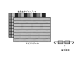
- FIG. 15 illustrates a three-dimensional image display method using a polarization method using a micropole.
- the liquid crystal display LCD
- polarizing elements alternately arranged for each pixel row are arranged, and the liquid crystal display displays the image signal L for the left eye and the image for the right eye for each row of pixels.
- the signal R is output alternately.
- the left eye image and the right eye image are separated by polarized glasses corresponding to the left and right polarization directions.
- the corresponding polarization direction is indicated by diagonal lines.
- the principle of separating the left-eye image and the right-eye image by a polarization method using a micropole will be described with reference to FIG.
- the illustrated display device 10 includes a backlight 11, polarizing plates 12 a and 12 b, a liquid crystal display element 13, and a polarization control filter 14.
- the display device 10 alternately displays the right-eye images R1, R2, R3,... And the left-eye images L1, L2, L3,.
- R represents a right-eye image
- L represents a left-eye image
- numbers are serial numbers of pixel rows.
- the light from the backlight 11 is polarized by the polarizing plates 12 a and 12 b and the liquid crystal display element 13. Further, the light transmitted through the polarizing plate 12b is circularly polarized by the polarization control filter 14 disposed in front of the polarizing plate 12b.
- the polarization control filter 14 includes a polarization region 14a and a polarization region 14b each having a ⁇ 1/4 wavelength plate in order to circularly polarize the light transmitted through the polarizing plate 12b to either right circularly polarized light or left circularly polarized light. They are arranged corresponding to the pixel rows of the right-eye image or the left-eye image.
- the optical axes of the polarizing region 14a and the polarizing region 14b are orthogonal to each other.
- the light forming the right-eye images R1, R2, R3,... Is right-circularly polarized in the polarization region 14a, and the light forming the left-eye images L1, L2, L3,. .
- the polarizing glasses 20 include a right-eye image transmission unit 21 and a left-eye image transmission unit 22.
- the right-eye image transmission unit 21 includes a quarter-wave plate and a polarization lens (not shown) so that right-circularly polarized light can be transmitted.
- the left-eye image transmission unit 22 includes a -1/4 wavelength plate and a polarization lens (not shown) so that left-circularly polarized light can be transmitted.
- the right-eye image transmission unit 21 blocks left-circularly polarized light
- the left-eye image transmission unit 22 blocks right-circularly polarized light. Therefore, only the light forming the right eye images R1, R2, R3,... Is incident on the right eye of the viewer wearing the polarizing glasses 20, and the left eye images L1, L2, L3,. Only the light formed will be incident.
- the viewer When the viewer views the circularly polarized light through the polarizing glasses 20, the viewer can separate and visually recognize the right-eye image and the left-eye image having parallax, and stereoscopically view the light. it can.
- the display device using the polarization control filter has a problem that the light is not sufficiently divided at the boundary where the polarization state of the filter changes. If the light is not sufficiently divided, a part of the image for the right eye leaks to the left eye and a part of the image for the left eye leaks to the right eye, that is, crosstalk occurs.
- the polarization control filter 14 controls the direction of circularly polarized light by the two polarization regions 14a and 14b.
- the division of light becomes insufficient at the boundary between the polarizing region 14a and the polarizing region 14b
- the viewer views the light from the display device 10 through the polarizing glasses 20
- a part of the right-eye image is displayed.
- Crosstalk occurs in the left eye, in which part of the left-eye image leaks into the right eye.
- a method of arranging a black matrix at the boundary where the polarization state of the filter changes can be considered. By placing a black matrix at the boundary where the polarization state of the polarization control filter changes, part of the image for the right eye is not mixed into the left eye and part of the image for the left eye is not mixed into the right eye. In this way, the occurrence of crosstalk can be suppressed.
- FIG. 17 shows an example of the polarization control filter 14 provided with the black matrix 14c.
- the arrangement of pixels in the liquid crystal display element 13 is also shown.
- One unit pixel of the liquid crystal display element 13 has three colors of liquid crystal, a red liquid crystal cell 13a that emits red (R), a green liquid crystal cell 13b that emits green (G), and a liquid crystal cell pixel 13c that emits blue (B). Composed of a combination of cells.
- the liquid crystal cells of each horizontal line are arranged in different colors.
- the display device 10 alternately displays the right-eye images R1, R2, R3,... And the left-eye images L1, L2, L3,. To do.
- the black matrix 14c is arranged corresponding to a boundary portion between a row of pixels displaying the left-eye image and a row of pixels displaying the right-eye image. Therefore, the light is divided at the boundary between the polarizing region 14a and the polarizing region 14b, so that the occurrence of crosstalk when the viewer views the light from the display device 0 through the polarizing glasses 20 is suppressed.
- a normal two-dimensional image can be displayed in addition to a three-dimensional image that can be viewed stereoscopically by the viewer.
- the right-eye image and the left-eye image are displayed at the same time, and each polarization state is changed by the polarization control filter, and the viewer wears glasses whose polarization state is changed on the left and right. View.
- the viewer when displaying a two-dimensional image, the viewer only needs to take off his / her glasses.
- a black matrix is placed at the boundary where the polarization state of the polarization control filter changes, the luminance is reduced by the amount blocked by the black matrix when a normal two-dimensional image is displayed on the screen. There is a problem of end.
- An object of the present invention is to display both a two-dimensional image and a three-dimensional image, suppress the occurrence of crosstalk when displaying the three-dimensional image, and reduce the luminance when displaying the two-dimensional image.
- An object of the present invention is to provide an excellent display device capable of avoiding deterioration.
- One pixel is formed by a plurality of color component cells each having an individual bus line, and the plurality of pixels are sequentially arranged in a horizontal direction and a vertical direction.
- a display panel for displaying a two-dimensional image or a three-dimensional image
- a polarization control filter disposed on the front surface of the display panel and alternately changing a polarization state of light transmitted through the panel portion for each predetermined horizontal region
- a signal control unit for controlling a signal applied to the bus line when displaying a two-dimensional image or a three-dimensional image on the display panel; Comprising The polarization control filter is arranged so that each boundary where the polarization state changes falls within the range of one row of cells, When displaying the three-dimensional image, the signal control unit displays the signal to the bus line so that each row of cells located at the boundary where the polarization state of the polarization control filter changes is displayed in black.
- each pixel of the display panel includes cells of three colors of red, green, and blue.
- the composition ratio of red, green and blue in the display panel is the same as when displaying a two-dimensional image.
- a boundary where the polarization state of the polarization control filter changes is disposed.
- each pixel of the display panel of the display device according to claim 1 includes cells of three colors of red, green, and blue and cells of colors other than red, green, and blue, respectively.
- the signal control unit is configured to control the application of the signal to the bus line so that the cells other than red, green, and blue are displayed in black when displaying a three-dimensional image. Yes.
- each pixel of the display panel of the display device has N-color cells arranged in order in the vertical direction (where N is an integer of 2 or more),
- the display panel has a horizontal arrangement structure in which cells of each horizontal line are arranged in the same color.
- the polarization control filter is arranged so that each boundary where the polarization state changes falls within the range of one row every N rows of cells. Then, when displaying the three-dimensional image, the signal control unit displays the one row of every three rows of cells positioned at the boundary where the polarization state of the polarization control filter changes in black. It is configured to control application of a signal to the line.
- each pixel of the display panel of the display device is configured so that cells of four colors including three colors of red, green, and blue and colors other than the three colors are vertically aligned.
- the display panel has a horizontal arrangement structure in which cells of each horizontal line are arranged in the same color.
- the polarization control filter is arranged so that each boundary where the polarization state changes falls within the range of one row of cells of colors other than the three colors.
- the signal control unit controls application of the signal to the bus line so that each row of cells of colors other than the three colors is displayed in black when displaying a three-dimensional image. It is configured.
- each pixel of the display panel of the display device includes two rows of four-color cells including three colors of red, green, and blue and colors other than the three colors. It is arranged in two rows.
- the polarization control filter is arranged so that each boundary where the polarization state changes falls within the range of one row every two rows of cells. Then, when displaying the three-dimensional image, the signal control unit displays the one line of every two rows of cells positioned at the boundary where the polarization state of the polarization control filter changes in black so that the bus It is configured to control application of a signal to the line.
- the display panel of the display device described in claim 1 sequentially arranges cells of four colors including three colors of red, green and blue and colors other than the three colors in the horizontal direction. The formation position of each color is shifted by two columns for each cell row.
- the polarization control filter is arranged so that each boundary where the polarization state changes falls within the range of one row every other row of the cell. Then, when displaying a three-dimensional image, the signal control unit displays the one line of every other cell located at the boundary where the polarization state of the polarization control filter changes in black, so that the bus It is configured to control application of a signal to the line.
- the display panel of the display device sequentially arranges cells of four colors including three colors of red, green and blue and colors other than the three colors in the horizontal direction.
- the formation position of each color is shifted by two columns for each cell row.
- the polarization control filter is arranged so that each boundary where the polarization state changes falls within the range of one row every two rows of cells.
- the signal control unit displays the one line of every two rows of cells positioned at the boundary where the polarization state of the polarization control filter changes in black so that the bus It is configured to control application of a signal to the line.
- both a two-dimensional image and a three-dimensional image can be displayed, the occurrence of crosstalk when displaying a three-dimensional image is suppressed, and the luminance is reduced when displaying a two-dimensional image. It is possible to provide an excellent display device capable of avoiding the decrease.
- a row of pixels always displaying black is provided, and a boundary portion where the polarization state of the polarization control filter changes is arranged so as to coincide with the row of pixels displaying black.
- FIG. 1 is a diagram schematically illustrating a functional configuration of a display device 100 that displays both a two-dimensional image and a three-dimensional image.
- FIG. 2 is a diagram showing the configuration of the image display unit 110 in detail.
- FIG. 3 is a diagram showing a configuration example of a liquid crystal panel that realizes light division at a boundary where the polarization state of the polarization control filter changes without using a black matrix (when a normal two-dimensional image is displayed). is there.
- FIG. 4 is a diagram showing an example of a configuration of a liquid crystal panel that realizes light division at a boundary where the polarization state of the polarization control filter changes without using a black matrix (when a three-dimensional image is displayed).
- FIG. 1 is a diagram schematically illustrating a functional configuration of a display device 100 that displays both a two-dimensional image and a three-dimensional image.
- FIG. 2 is a diagram showing the configuration of the image display unit 110 in detail.
- FIG. 3 is a
- FIG. 5 is a diagram showing another configuration example of a liquid crystal panel that realizes light division at a boundary where the polarization state of the polarization control filter changes without using a black matrix (when a normal two-dimensional image is displayed). It is.
- FIG. 6 is a diagram showing another example of the configuration of a liquid crystal panel that realizes light division at a boundary where the polarization state of the polarization control filter changes without using a black matrix (when a three-dimensional image is displayed).
- FIG. 7 is a diagram showing still another configuration example of a liquid crystal panel that realizes light division at a boundary where the polarization state of the polarization control filter changes without using a black matrix (when a normal two-dimensional image is displayed) ).
- FIG. 8 is a diagram showing still another configuration example of the liquid crystal panel that realizes the light division at the boundary where the polarization state of the polarization control filter changes without using the black matrix (when a three-dimensional image is displayed). is there.
- FIG. 9 is a diagram showing still another configuration example of a liquid crystal panel that realizes light division at a boundary where the polarization state of the polarization control filter changes without using a black matrix (when a normal two-dimensional image is displayed) ).
- FIG. 10 is a diagram showing still another configuration example of a liquid crystal panel that realizes light division at a boundary where the polarization state of the polarization control filter changes without using a black matrix (when a three-dimensional image is displayed). is there.
- FIG. 9 is a diagram showing still another configuration example of a liquid crystal panel that realizes light division at a boundary where the polarization state of the polarization control filter changes without using a black matrix (when a normal two-dimensional image is displayed).
- FIG. 10 is a
- FIG. 11 is a diagram showing still another configuration example of a liquid crystal panel that realizes light division at a boundary where the polarization state of the polarization control filter changes without using a black matrix (when a normal two-dimensional image is displayed) ).
- FIG. 12 is a diagram showing still another configuration example of a liquid crystal panel that realizes light division at a boundary where the polarization state of the polarization control filter changes without using a black matrix (when a three-dimensional image is displayed). is there.
- FIG. 13 is a diagram showing still another configuration example of a liquid crystal panel that realizes light division at a boundary where the polarization state of the polarization control filter changes without using a black matrix (when a normal two-dimensional image is displayed) ).
- FIG. 14 is a diagram showing still another configuration example of a liquid crystal panel that realizes light division at a boundary where the polarization state of the polarization control filter changes without using a black matrix (when a three-dimensional image is displayed). is there.
- FIG. 15 is a diagram for explaining a display method of a three-dimensional image by a polarization method using a micropole.
- FIG. 16 is a diagram for explaining the principle of separating a left-eye image and a right-eye image by a polarization method using a micropole.
- FIG. 17 is a diagram illustrating an example of the polarization control filter 14 including the black matrix 14c.
- FIG. 1 schematically shows a functional configuration of a display device 100 that displays both a two-dimensional image and a three-dimensional image.
- FIG. 1 also shows polarized glasses 200 used by the viewer to perceive an image displayed by the display device 100 as a stereoscopic image.
- the display device 100 includes an image display unit 110, a video signal control unit 120, and a timing control unit 140.
- the image display unit 110 displays an image according to a signal applied from the outside.
- the image display unit 110 includes a display panel 112, a gate driver 113, a data driver 114, and a light source 162.
- the display panel 112 encloses liquid crystal molecules having a predetermined alignment state between transparent plates such as glass, and displays an image in response to application of an external signal. Application of a signal to the display panel 112 is executed by the gate driver 113 and the data driver 114.
- the display panel 112 will be described as being driven by the TN (Twisted Nematic) method, but the gist of the present invention is not limited to a specific driving method, and the VA (Virtual Alignment) method or IPS (IPS) method is used. It may be driven by a driving method such as an In-Place-Switching method.
- the driving method of the display panel 112 is a method other than the TN method, liquid crystal molecules that are not twisted with respect to the polarizing plate may be sealed in the liquid crystal panel 112.
- the gate driver 113 is a drive circuit that drives a gate bus line (not shown) of the display panel 112, and outputs a signal to the gate bus line in accordance with a signal transmitted from the timing control unit 140.
- the data driver 114 is a drive circuit that generates a signal to be applied to a data line (not shown) of the display panel 112, and a signal to be applied to the data line in accordance with a signal transmitted from the timing control unit 140. Is generated and output.
- the light source 162 is a backlight provided at the back of the image display unit 110 when viewed from the viewer side.
- non-polarized white light is emitted from the light source 162 to the display panel 112 located on the viewer side.
- one pixel is formed by cells of a plurality of color components, such as OLED (Organic Light Emitting Diode) and LED (Light Emitting Diode), and a plurality of pixels are sequentially arranged in the horizontal and vertical directions.
- OLED Organic Light Emitting Diode
- LED Light Emitting Diode
- the present invention can be similarly applied to these displays.
- the video signal control unit 120 When receiving the transmission of the video signal from the outside of the video signal control unit 120, the video signal control unit 120 makes the received video signal suitable for displaying a three-dimensional image or a two-dimensional image on the image display unit 110. As described above, various signal processes are executed and output.
- the video signal subjected to the signal processing by the video signal control unit 120 is transmitted to the timing control unit 140.
- the video signal control unit 120 When the right eye video signal and the left eye video signal are transmitted, the video signal control unit 120 generates a video signal for a three-dimensional image from the two video signals. Specifically, the video signal control unit 120 displays the three-dimensional image so that the image for the right eye is displayed on the odd lines of the scanning lines of the display panel in the image display unit 110 and the image for the left eye is displayed on the even lines. A video signal for is generated.
- the timing control unit 140 generates a pulse signal used for the operation of the gate driver 113 and the data driver 114 in accordance with the signal transmitted from the video signal control unit 120. Then, when the gate driver 113 and the data driver 114 receive the pulse signal generated by the timing control unit 140, an image corresponding to the signal transmitted from the video signal control unit 120 is displayed on the display panel 112.
- the image display unit 110 includes a polarization control filter (described later) that further circularly polarizes light transmitted through the polarizing plate.
- the light incident on the polarization control filter passes through the polarization control filter and is circularly polarized in a predetermined direction and emitted.
- the viewer sees the light circularly polarized by the polarization control filter through the right-eye image transmission unit 212 and the left-eye image transmission unit 214 of the polarizing glasses 200, thereby viewing the image displayed on the image display unit 110 in three dimensions. Can be seen.
- the display device 100 is illustrated as a television receiver. However, for example, a monitor, a portable game machine, a cellular phone, or a portable music playback device that is used in connection with a personal computer or other electronic device. It may be.
- FIG. 2 shows the configuration of the image display unit 110 in detail.
- the illustrated image display unit 110 includes a light source 162, polarizing plates 164 a and 164 b, a liquid crystal panel 166, and a polarization control filter 168.
- the polarizing plates 164a and 164b, the liquid crystal panel 166, and the polarization control filter 168 constitute the display panel 112 shown in FIG.
- the light source 162 is provided at the innermost part of the image display unit 110 when viewed from the viewer side. When displaying an image on the image display unit 110, non-polarized white light is emitted from the light source 162 to the display panel 112 disposed on the viewer side.
- a light emitting diode, a cold cathode tube, or the like can be used.
- the illustrated light source 162 is a surface light source, the gist of the present invention is not limited to a specific light source.
- a light source may be disposed around the display panel 112 and light may be emitted to the display panel 112 by diffusing light from the light source with a diffusion plate or the like.
- a point light source and a condensing lens may be combined instead of the surface light source.
- a polarizing plate 164 a is disposed between the light source 162 and the liquid crystal panel 166.
- the polarizing plate 164a has a transmission axis and an absorption axis orthogonal to the transmission axis.
- the polarizing plate 164a transmits and absorbs a component having a polarization axis parallel to the transmission axis direction in the non-polarized white light. Blocks light with a polarization axis parallel to the axial direction.
- the light transmitted through the polarizing plate 164a is emitted to the liquid crystal panel 166.
- the liquid crystal panel 166 is configured by enclosing liquid crystal molecules having a predetermined alignment state between two transparent plates such as a glass substrate.
- the driving method of the display panel 112 is the TN method
- liquid crystal oriented by twisting a predetermined angle for example, 90 degrees
- the driving method of the display panel 112 is a VA method
- liquid crystal molecules are aligned perpendicular to the electrodes.
- the liquid crystal panel 166 constitutes, for example, a TFT (Thin Film Transistor) type liquid crystal display panel.
- the light incident on the liquid crystal panel 166 is emitted from the liquid crystal panel 166 with the incident light shifted by 90 degrees when no voltage is applied to the liquid crystal panel 166.
- the twist of the liquid crystal is eliminated, so that incident light is emitted from the liquid crystal panel 166 in the same polarization state.
- the liquid crystal panel 166 includes a plurality of pixels arranged in the horizontal direction and the vertical direction, respectively, and an image is displayed by driving each pixel by applying a pulse signal from the gate driver 113 and the data driver 114. .
- an image perceived by the viewer as a stereoscopic 3D image is displayed on the image display unit 110
- the right-eye image and the left-eye image are alternately displayed on the liquid crystal panel 166 row by pixel.
- the image display unit 110 is configured to display the right-eye image on the odd-numbered rows and the left-eye image on the even-numbered rows of the liquid crystal panel 166, respectively.
- a polarizing plate 164b is disposed in front of the liquid crystal panel 166 when viewed from the viewer side.
- the polarizing plate 164b has a transmission axis and an absorption axis orthogonal to the transmission axis.
- the transmission axis of the polarizing plate 164b is orthogonal to the transmission axis of the polarizing plate 164a
- the absorption axis of the polarizing plate 164b is orthogonal to the absorption axis of the polarizing plate 164a.
- the polarizing plate 164b When the light transmitted through the liquid crystal panel 166 enters the polarizing plate 164b, the polarizing plate 164b transmits a component having a polarization axis parallel to the transmission axis direction out of the light transmitted through the liquid crystal panel 166, and the absorption axis direction. Blocks light with a polarization axis parallel to the. The light transmitted through the polarizing plate 164b is emitted to the polarization control filter 168.
- the polarization control filter 168 is disposed in front of the polarizing plate 164b when viewed from the viewer side.
- the polarization control filter 168 is provided with a polarization region 169a and a polarization region 169b each having a quarter wavelength plate in order to circularly polarize the light transmitted through the polarizing plate 164b to either right circularly polarized light or left circularly polarized light. ing.
- the optical axes of the polarizing region 169a and the polarizing region 169b are orthogonal to each other. For example, the light forming the right-eye images R1, R2, R3,... Is right-circularly polarized in the polarization region 169a, and the light forming the left-eye images L1, L2, L3,. .
- the liquid crystal panel 166 When displaying an image perceived by the viewer as a stereoscopic three-dimensional image on the image display unit 110, as described above, the liquid crystal panel 166 alternately displays the right-eye image and the left-eye image pixel by row. The Specifically, the right-eye image is displayed on the odd-numbered rows of the liquid crystal panel 166, and the left-eye image is displayed on the even-numbered rows. Accordingly, the polarization control filter 168 includes the polarizing plate 164b so that the polarizing region 169a is positioned so as to correspond to the odd-numbered rows of the liquid crystal panel 166 and the polarizing region 169b is positioned so as to correspond to the even-numbered rows of the liquid crystal panel 166. It is provided in front (viewer side).
- the viewer can perceive the image displayed on the image display unit 110 as a stereoscopic three-dimensional image by viewing the light polarized by the polarization control filter 168 through the polarizing glasses 200.
- a row of pixels that always displays black when displaying a three-dimensional image is provided, and a boundary portion where the polarization state of the polarization control filter changes coincides with the row of pixels that display black.
- a method of suppressing crosstalk without using a black matrix is proposed by disposing light at the boundary where the polarization state of the polarization control filter changes.
- This method can be applied to both a horizontal arrangement structure in which liquid crystal cells in each horizontal line are arranged in the same color and a vertical arrangement structure in which liquid crystal cells in each horizontal line are arranged in different colors.
- the horizontal arrangement structure can reduce the number of data lines to 1/3 compared with the vertical arrangement structure in which the liquid crystal cells of each horizontal line are arranged in different colors, and the manufacturing cost is low.
- some configuration examples of the display panel 112 that suppress crosstalk without using a black matrix will be described in detail.
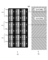
- FIG. 3 shows a configuration example of a liquid crystal panel that realizes light division at the boundary where the polarization state of the polarization control filter changes without using a black matrix.
- One unit pixel of the illustrated liquid crystal panel 166 is composed of three columns of liquid crystal cells.
- a red liquid crystal cell 172 emitting red, a green liquid crystal cell 174 emitting green, and a blue liquid crystal cell 176 emitting blue are arranged in a horizontal direction.
- the liquid crystal panel 166 has a vertical arrangement structure in which a plurality of pixels are repeatedly arranged in the horizontal direction and the vertical direction, and the liquid crystal cells of each horizontal line are arranged in different colors.
- the red liquid crystal cell 172 is divided into two sub-cells 173a and 173b having substantially the same size in the vertical direction
- the green liquid crystal cell 174 is divided into two sub-cells 175a and 175b having substantially the same size in the vertical direction
- the blue liquid crystal cell 176 is divided into two sub-cells 177a and 177b having substantially the same size in the vertical direction.
- the sub cells 173a, 175a, and 177a have the same length in the vertical direction, and are repeatedly arranged in the order of the sub pixels 173a, 175a, and 177a in the horizontal direction.
- the sub-pixels 173b, 175b, and 177b have the same length in the vertical direction and are repeatedly arranged in the order of the sub-pixels 173b, 175b, and 177b in the horizontal direction.
- FIG. 3 also shows a polarization control filter 168 together with the liquid crystal panel 166.
- the liquid crystal panel 166 and the polarization control filter 168 are drawn side by side horizontally, but in the actual display device 100, the polarization control filter 168 is disposed on the front surface (viewer side) of the liquid crystal panel 166. Yes.
- the polarization control filter 168 is configured by alternately arranging, in the vertical direction, a polarization region 169a that circularly polarizes in the right circular polarization direction and a polarization region 169b that circularly polarizes in the left circular polarization direction.
- the difference in the direction of circularly polarized light for each region is represented by diagonal lines.
- the polarization control filter 168 is disposed so that the boundary between the polarization region 169a and the polarization region 169b falls within the range of each of the sub cells 173a, 175a, and 177a.
- the polarization regions 169a and 169b of the polarization control filter 168 are displayed. Black is displayed in the sub-cells 173a, 175a, and 177a located at the boundary with the other, and the original image is displayed by the other sub-cells 173b, 175b and 177b.
- the display of each sub-cell can be controlled by the video signal control unit 120.
- the video signal control unit 120 displays the right-eye image on the odd-numbered lines and the left-eye image on the even-numbered lines of the liquid crystal panel 166.
- Signal processing is executed in Then, the video signal control unit 120 transmits a signal from the video signal control unit 120 to the timing control unit 140 so that black is displayed for the rows of the sub cells 173a, 175a, and 177a in each pixel. do it. Displaying black in the sub-cell is realized by inputting a luminance signal of 0 gradation.
- the sub cells 173 a, 175 a, and 177 a displaying black color serve as a black matrix of the polarization control filter 168. Therefore, when displaying an image for allowing the viewer to perceive it as a stereoscopic image, the sub-cells 173a, 175a, and 177a are displayed in black, so that the occurrence of crosstalk can be suppressed.
- the gamma correction when displaying a three-dimensional image, the gamma correction is appropriately applied in a state where the sub-pixels 173a, 175a, and 177a are removed, and when displaying a two-dimensional image, The parameter is changed so that gamma correction is appropriately applied with all sub-pixels included.
- the image displayed on the image display unit 110 is corrected by correcting the image quality of the image displayed on the image display unit 110 with parameters suitable for displaying the three-dimensional image different from the case of displaying the two-dimensional image. It becomes possible to improve the image quality of a three-dimensional image.
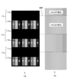
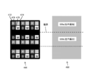
- FIG. 5 shows another configuration example of the liquid crystal panel that realizes the light division at the boundary where the polarization state of the polarization control filter changes without using the black matrix.
- One unit pixel of the illustrated liquid crystal panel 266 is composed of three rows of liquid crystal cells, and three colors of a red liquid crystal cell 272, a green liquid crystal cell 274, and a blue liquid crystal cell 276 are arranged in the vertical direction.
- the liquid crystal panel 266 has a horizontal arrangement structure in which a plurality of pixels are repeatedly arranged in the horizontal direction and the vertical direction, and the liquid crystal cells of each horizontal line are arranged in the same color.
- the horizontal arrangement structure can reduce the number of data lines to 1/3 compared with the vertical arrangement structure in which the liquid crystal cells of each horizontal line are arranged in different colors, and the manufacturing cost is low.
- FIG. 5 also shows a polarization control filter 268 together with the liquid crystal panel 266.
- the liquid crystal panel 266 and the polarization control filter 268 are drawn horizontally side by side, but in the actual display device 100, the polarization control filter 268 is disposed on the front surface (viewer side) of the liquid crystal panel 266. Yes.
- the polarization control filter 268 is configured by alternately arranging, in the vertical direction, polarization regions 269a that circularly polarize in the right circular polarization direction and polarization regions 269b that circularly polarize in the left circular polarization direction.
- the difference in the direction of circularly polarized light for each region is represented by diagonal lines.
- both the polarization regions 269a and 269b have a width obtained by adding one liquid crystal cell to the width of one pixel row.
- the polarization control filter 268 is disposed so that the boundary between the polarizing region 269a and the polarizing region 269b is within the range of the red liquid crystal cell 272, the green liquid crystal cell 274, and the blue liquid crystal cell 276 in order in the vertical direction. .
- the polarization region 269a and the polarization region 269b of the polarization control filter 268 are displayed.
- the original image is displayed by the green liquid crystal cell 274 and the blue liquid crystal cell 276.
- the display of each liquid crystal cell can be controlled by the video signal control unit 120.
- the video signal control unit 120 displays the right-eye image on the odd-numbered lines and the left-eye image on the even-numbered lines of the liquid crystal panel 266.
- Signal processing is executed in Then, the video signal control unit 120 transmits the black color to the liquid crystal cell located at the boundary between the polarization region 269a and the polarization region 269b of the polarization control filter 268, and then the timing control unit 140 from the video signal control unit 120. It is sufficient to transmit a signal. Displaying black in the liquid crystal cell is realized by inputting a luminance signal of 0 gradation.
- the liquid crystal cell located at the boundary between the polarization region 269a and the polarization region 269b of the polarization control filter 268 functions as a black matrix of the polarization control filter 268 by displaying black. Therefore, when displaying an image for allowing the viewer to perceive it as a stereoscopic image, the liquid crystal cell positioned at the boundary between the polarization region 269a and the polarization region 269b of the polarization control filter 268 is displayed in black, thereby The occurrence of talk can be suppressed.
- black is displayed on the liquid crystal cell located at the boundary between the polarization region 269a and the polarization region 269b of the polarization control filter 268, and deviated from the boundary between the polarization region 269a and the polarization region 269b.
- the liquid crystal cells are arranged in order of red, green, blue, black, red, green, blue, black,. .
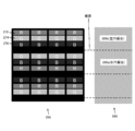
- FIG. 7 shows still another configuration example of the liquid crystal panel that realizes the light division at the boundary where the polarization state of the polarization control filter changes without using the black matrix.
- One unit pixel of the illustrated liquid crystal panel 366 includes four rows of liquid crystal cells.
- the red liquid crystal cell 372 the green liquid crystal cell 374, and the blue liquid crystal cell 376
- four colors of liquid crystal cells 378 of colors other than red, green, and blue are provided. Are arranged in the vertical direction in order.
- the liquid crystal cell 378 is described as white (W).
- W white
- the liquid crystal panel 366 has a horizontal arrangement structure in which a plurality of pixels are repeatedly arranged in the horizontal direction and the vertical direction, and the liquid crystal cells of each horizontal line are arranged in the same color.
- FIG. 7 also shows a polarization control filter 368 together with the liquid crystal panel 366.
- the liquid crystal panel 366 and the polarization control filter 368 are drawn side by side and drawn horizontally, but in the actual display device 100, the polarization control filter 368 is disposed on the front surface (viewer side) of the liquid crystal panel 366. Yes.
- the polarization control filter 368 is configured by alternately arranging, in the vertical direction, polarization regions 369a that circularly polarize in the right circular polarization direction and polarization regions 369b that circularly polarize in the left circular polarization direction.
- the difference in the direction of circularly polarized light for each region is represented by diagonal lines. Similar to the example shown in FIG. 5, both the polarization regions 369a and 369b have a width obtained by adding one liquid crystal cell to the width of one row of pixels.
- a polarization control filter 368 is disposed so that the boundary between the polarizing region 369a and the polarizing region 369b falls within the range of the white liquid crystal cell 378.
- the image is displayed on the liquid crystal panel 366 in all the liquid crystal cells 372, 374, 376, and 378.
- a normal image is displayed on the display device 100, it can be seen that there is no black matrix.
- a higher-luminance image is displayed on the image display unit 110 than when the black matrix 14c is used as the polarization control filter (see FIG. 17). It is possible to make it.
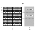
- the polarization region 369a and the polarization region 369b of the polarization control filter 368 are displayed.
- Black is displayed on the white liquid crystal cell 378 located at the boundary between the other, the other red liquid crystal cell 372, the green liquid crystal cell 374, and the blue liquid crystal cell 376 that are out of the boundary between the polarization region 369 a and the polarization region 369 b of the polarization control filter 368.
- the display of each liquid crystal cell can be controlled by the video signal control unit 120.
- the video signal control unit 120 displays the right-eye image on the odd-numbered rows and the left-eye image on the even-numbered rows of the liquid crystal panel 366.
- Signal processing is executed in Then, the video signal control unit 120 performs timing control from the video signal control unit 120 so that the white liquid crystal cell 378 positioned at the boundary between the polarization region 369a and the polarization region 369b of the polarization control filter 368 displays black.
- a signal may be transmitted to the unit 140. Displaying black in the white liquid crystal cell 378 is realized by inputting a luminance signal of 0 gradation.
- the white liquid crystal cell 378 positioned at the boundary between the polarization region 369a and the polarization region 369b of the polarization control filter 368 displays black and thus acts as a black matrix of the polarization control filter 368. Therefore, when displaying an image for allowing the viewer to perceive it as a stereoscopic image, the white liquid crystal cell 378 is displayed in black, whereby occurrence of crosstalk can be suppressed.
- the red liquid crystal cell 372 and the green liquid crystal are displayed in each pixel even when a three-dimensional image is displayed.
- the original image is displayed from all of the cell 374 and the blue liquid crystal cell 376. Therefore, crosstalk can be improved without losing the color reproduction range and resolution when displaying a three-dimensional image.
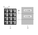
- FIG. 9 shows still another configuration example of the liquid crystal panel that realizes the light division at the boundary where the polarization state of the polarization control filter changes without using the black matrix.
- one unit pixel includes four colors of a red liquid crystal cell 472, a green liquid crystal cell 474, a blue liquid crystal cell 476, and liquid crystal cells 478 of other colors.
- one unit pixel is constituted by a liquid crystal cell of 2 rows and 2 columns.
- the liquid crystal cell 478 is described as white (W).
- a red liquid crystal cell 472 and a green liquid crystal cell 474, and a blue liquid crystal cell 476 and a white liquid crystal cell 478 are adjacent to each other in the horizontal direction.
- each liquid crystal cell is a square of the same size, and the unit pixel is a square whose side is twice as long as the liquid crystal cell.
- FIG. 9 also shows a polarization control filter 468 together with the liquid crystal panel 466.
- the liquid crystal panel 466 and the polarization control filter 468 are drawn side by side horizontally, but in the actual display device 100, the polarization control filter 468 is disposed on the front surface (viewer side) of the liquid crystal panel 466. Yes.
- the polarization control filter 468 is configured by alternately arranging, in the vertical direction, polarization regions 469a that circularly polarize in the right circular polarization direction and polarization regions 469b that circularly polarize in the left circular polarization direction.
- the difference in the direction of circularly polarized light for each region is represented by diagonal lines.
- Each of the polarization regions 469a and 469b has a width obtained by adding one liquid crystal cell to the width of one pixel row.
- the boundary between the polarizing region 469a and the polarizing region 469b is a range of rows of liquid crystal cells in which red liquid crystal cells 472 and green liquid crystal cells 474 are alternately arranged in the vertical direction, blue liquid crystal cells 476 and white liquid crystal cells.
- Polarization control filters 468 are arranged so as to alternately fall within the range of liquid crystal cell rows in which 478 are alternately arranged.
- the boundary between the polarizing region 469a and the polarizing region 469b is arranged every two rows of the liquid crystal cell in the vertical direction.
- the polarization region 469a and the polarization region 469b of the polarization control filter 468 are used. Black is displayed on one line of the liquid crystal cell located at the boundary between the two and the original image is displayed on the other line of the liquid crystal cell outside the boundary between the polarization region 469a and the polarization region 469b of the polarization control filter 468. As can be seen from FIG.
- the display of each liquid crystal cell can be controlled by the video signal control unit 120.
- the video signal control unit 120 displays the right-eye image on the odd-numbered rows and the left-eye image on the even-numbered rows of the liquid crystal panel 466.
- Signal processing is executed in Then, the video signal control unit 120 performs timing from the video signal control unit 120 to display black for one row of the liquid crystal cells located at the boundary between the polarization region 469a and the polarization region 469b of the polarization control filter 468.
- a signal may be transmitted to the control unit 140. Displaying black in the liquid crystal cell is realized by inputting a luminance signal of 0 gradation.
- One row of the liquid crystal cell positioned at the boundary between the polarization region 469a and the polarization region 469b of the polarization control filter 468 displays black and thereby acts as a black matrix of the polarization control filter 468. Therefore, when displaying an image for allowing the viewer to perceive it as a stereoscopic image, by displaying one row of the liquid crystal cells located at the boundary between the polarizing region 469a and the polarizing region 469b in black, crosstalk Occurrence can be suppressed.
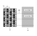
- FIG. 11 shows still another configuration example of the liquid crystal panel that realizes the light division at the boundary where the polarization state of the polarization control filter changes without using the black matrix.
- the liquid crystal panel 566 shown in the figure forms one unit pixel by a liquid crystal cell of 2 rows and 2 columns as in the example shown in FIG. 9, but is different in that it employs a so-called pen tile arrangement method. That is, the liquid crystal cells are arranged in the order of the red liquid crystal cell 572, the green liquid crystal cell 574, the blue liquid crystal cell 576, and the white liquid crystal cell 578 in each row, which is different from the example of FIG. 9 in which only two colors are arranged for each row. . In addition, the formation positions of the liquid crystal cells of each color are shifted by two columns for each row. For example, a blue liquid crystal cell 576 is formed under the red liquid crystal cell 574 and a white liquid crystal cell 578 is formed under the green liquid crystal cell 574. Is formed.
- FIG. 11 also shows a polarization control filter 568 together with the liquid crystal panel 566.
- the liquid crystal panel 466 and the polarization control filter 568 are drawn side by side and drawn horizontally, but in the actual display device 100, the polarization control filter 568 is disposed on the front surface (viewer side) of the liquid crystal panel 566. Yes.
- the polarization control filter 568 is configured by alternately arranging, in the vertical direction, polarization regions 569a that circularly polarize in the right circular polarization direction and polarization regions 569b that circularly polarize in the left circular polarization direction.
- the difference in the direction of circularly polarized light for each region is represented by diagonal lines.
- Both polarization regions 569a and 569b have a width corresponding to two rows of liquid crystal cells. Then, the polarization control filter 568 is disposed so that the boundary between the polarizing region 569a and the polarizing region 569b falls within the range of one row of the liquid crystal cell every other row of the liquid crystal cell.
- the polarization region 569a and the polarization region 569b of the polarization control filter 568 are displayed. Black is displayed on one line of the liquid crystal cell located at the boundary between and the original image is displayed on the other line of the liquid crystal cell outside the boundary between the polarization region 569a and the polarization region 569b of the polarization control filter 568. As can be seen from FIG. 12, the liquid crystal cells are displayed in black every other row.
- the display of each liquid crystal cell can be controlled by the video signal control unit 120.
- the video signal control unit 120 displays the right-eye image on the odd-numbered rows and the left-eye image on the even-numbered rows of the liquid crystal panel 566.
- Signal processing is executed in Then, the video signal control unit 120 performs timing from the video signal control unit 120 so as to display black for one row of the liquid crystal cell located at the boundary between the polarization region 569a and the polarization region 569b of the polarization control filter 568.
- a signal may be transmitted to the control unit 140. Displaying black in the liquid crystal cell is realized by inputting a luminance signal of 0 gradation.
- One row of the liquid crystal cell positioned at the boundary between the polarization region 569a and the polarization region 569b of the polarization control filter 568 displays black so that it acts as a black matrix of the polarization control filter 568. Therefore, when displaying an image for allowing the viewer to perceive it as a stereoscopic image, by displaying one row of the liquid crystal cells located at the boundary between the polarizing region 569a and the polarizing region 569b in black, crosstalk Occurrence can be suppressed. In addition, since the ratio lost due to black display is uniform among the color components (that is, the composition ratio of red, green, and yellow is the same as when displaying a two-dimensional image), it is not necessary to cause a color shift during three-dimensional display. .
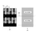
- FIG. 13 shows still another configuration example of the liquid crystal panel that realizes the light division at the boundary where the polarization state of the polarization control filter changes without using the black matrix.
- the liquid crystal panel 666 shown in FIG. 11 employs a pen tile arrangement method, similarly to the example shown in FIG. FIG. 13 also shows the polarization control filter 668 together with the liquid crystal panel 566, but both the polarization regions 669a and 669b have a width corresponding to three rows of liquid crystal cells, and the boundary between the polarization region 669a and the polarization region 669b.
- 11 is different from FIG. 11 in that the polarization control filter 568 is disposed so that the liquid crystal cell falls within the range of one row of the liquid crystal cell every two rows of the liquid crystal cell.
- the image is displayed on the liquid crystal panel 566 in the liquid crystal cells 672, 674, 676, and 678 in all rows as described above. Since the black matrix does not exist, it is possible to display a high-luminance two-dimensional image on the image display unit 110.
- the polarization region 669a and the polarization region 669b of the polarization control filter 668 are displayed. Black is displayed on one line of the liquid crystal cell located at the boundary between and the original image is displayed on the other line of the liquid crystal cell outside the boundary between the polarization region 669a and the polarization region 569b of the polarization control filter 668. As can be seen from FIG. 14, the liquid crystal cells are displayed in black every two rows.
- One row of the liquid crystal cell located at the boundary between the polarization region 669a and the polarization region 669b of the polarization control filter 668 displays black so that it acts as a black matrix of the polarization control filter 668. Therefore, when displaying an image for allowing the viewer to perceive it as a stereoscopic image, by displaying one row of the liquid crystal cells located at the boundary between the polarizing region 669a and the polarizing region 669b in black, crosstalk Occurrence can be suppressed. In addition, since the ratio lost due to black display is uniform among the color components (that is, the composition ratio of red, green, and yellow is the same as when displaying a two-dimensional image), it is not necessary to cause a color shift during three-dimensional display. .
- the former can increase the vertical resolution, and the latter can increase the degree of horizontal modification.
- the embodiment applied to the liquid crystal display has been described, but the gist of the present invention is not limited to this.
- the present invention is similarly applied to other displays in which one pixel is formed by cells of a plurality of color components, such as OLED and LED, and the plurality of pixels are sequentially arranged in the horizontal direction and the vertical direction. be able to.
- the present invention can be applied to a monitor, a portable game machine, a cellular phone, and a portable music player that are used in connection with an electronic device other than a television receiver. Further, it is possible to correspond to a display panel driving method such as a TN method, a VA method, or an IPS method.
- DESCRIPTION OF SYMBOLS 100 ...
- Display apparatus 110 ... Image display part 112 ... Liquid crystal panel 113 ... Gate driver 114 ... Data driver 120 ...
- Video signal control part 140 ... Timing control part 162 ...
Landscapes
- Engineering & Computer Science (AREA)
- Physics & Mathematics (AREA)
- General Physics & Mathematics (AREA)
- Computer Hardware Design (AREA)
- Theoretical Computer Science (AREA)
- Multimedia (AREA)
- Signal Processing (AREA)
- Chemical & Material Sciences (AREA)
- Crystallography & Structural Chemistry (AREA)
- Optics & Photonics (AREA)
- Testing, Inspecting, Measuring Of Stereoscopic Televisions And Televisions (AREA)
- Liquid Crystal (AREA)
Abstract
Priority Applications (5)
| Application Number | Priority Date | Filing Date | Title |
|---|---|---|---|
| CN201280002039.6A CN103003868B (zh) | 2011-03-22 | 2012-02-16 | 显示设备 |
| EP16170701.3A EP3079147B1 (fr) | 2011-03-22 | 2012-02-16 | Dispositif d'affichage |
| US13/698,115 US9349310B2 (en) | 2011-03-22 | 2012-02-16 | Display device for displaying two-dimensional and three-dimensional images without a black matrix |
| EP12760053.4A EP2551842B1 (fr) | 2011-03-22 | 2012-02-16 | Dispositif d'affichage |
| KR1020127029666A KR101963905B1 (ko) | 2011-03-22 | 2012-02-16 | 표시 장치 |
Applications Claiming Priority (2)
| Application Number | Priority Date | Filing Date | Title |
|---|---|---|---|
| JP2011-062081 | 2011-03-22 | ||
| JP2011062081A JP5768424B2 (ja) | 2011-03-22 | 2011-03-22 | 表示装置 |
Publications (1)
| Publication Number | Publication Date |
|---|---|
| WO2012127945A1 true WO2012127945A1 (fr) | 2012-09-27 |
Family
ID=46879109
Family Applications (1)
| Application Number | Title | Priority Date | Filing Date |
|---|---|---|---|
| PCT/JP2012/053683 WO2012127945A1 (fr) | 2011-03-22 | 2012-02-16 | Dispositif d'affichage |
Country Status (7)
| Country | Link |
|---|---|
| US (1) | US9349310B2 (fr) |
| EP (2) | EP3079147B1 (fr) |
| JP (1) | JP5768424B2 (fr) |
| KR (1) | KR101963905B1 (fr) |
| CN (1) | CN103003868B (fr) |
| TW (1) | TWI497469B (fr) |
| WO (1) | WO2012127945A1 (fr) |
Cited By (2)
| Publication number | Priority date | Publication date | Assignee | Title |
|---|---|---|---|---|
| WO2014087781A1 (fr) * | 2012-12-07 | 2014-06-12 | 堺ディスプレイプロダクト株式会社 | Dispositif d'affichage à cristaux liquides et procédé de pilotage dudit dispositif d'affichage à cristaux liquides |
| US20150146141A1 (en) * | 2013-11-26 | 2015-05-28 | Lg Display Co., Ltd. | 3-dimensional image display device |
Families Citing this family (5)
| Publication number | Priority date | Publication date | Assignee | Title |
|---|---|---|---|---|
| KR20120138205A (ko) * | 2011-06-14 | 2012-12-24 | 삼성디스플레이 주식회사 | 표시 장치 |
| US20130286005A1 (en) * | 2012-04-27 | 2013-10-31 | Shenzhen China Star Optoelectronics Technology Co. Ltd. | Three-Dimensional Display Device and Drive Method Thereof |
| JP6145721B2 (ja) | 2013-02-19 | 2017-06-14 | パナソニックIpマネジメント株式会社 | 画像表示装置 |
| CN104038754B (zh) * | 2014-06-07 | 2016-08-31 | 深圳市华星光电技术有限公司 | 显示装置及其显示图像的方法 |
| CN112558320B (zh) * | 2020-12-23 | 2022-12-09 | 维沃移动通信有限公司 | 显示面板和显示设备 |
Citations (3)
| Publication number | Priority date | Publication date | Assignee | Title |
|---|---|---|---|---|
| JP2001197523A (ja) * | 2000-01-12 | 2001-07-19 | Mixed Reality Systems Laboratory Inc | 立体表示装置、表示制御装置、表示制御方法、表示システムおよびプログラム記憶媒体 |
| JP2002365593A (ja) * | 2001-06-08 | 2002-12-18 | Sony Corp | 表示装置、位置調整パターン表示プログラム、記録媒体、偏光メガネ、及び表示装置のフィルター位置調整方法 |
| JP2010204389A (ja) | 2009-03-03 | 2010-09-16 | Sony Corp | 表示装置 |
Family Cites Families (22)
| Publication number | Priority date | Publication date | Assignee | Title |
|---|---|---|---|---|
| JPH05241551A (ja) * | 1991-11-07 | 1993-09-21 | Canon Inc | 画像処理装置 |
| JP2003202519A (ja) * | 2001-12-28 | 2003-07-18 | Canon Inc | 立体画像表示装置 |
| KR100546258B1 (ko) * | 2003-05-15 | 2006-01-26 | 엘지.필립스 엘시디 주식회사 | 수평 전계 인가형 액정 표시 패널 |
| JP2008076416A (ja) * | 2004-12-27 | 2008-04-03 | Sharp Corp | 表示パネルの駆動装置、表示パネル及びそれを備えた表示装置並びに表示パネルの駆動方法 |
| CN102122460B (zh) * | 2005-09-21 | 2012-08-29 | 夏普株式会社 | 显示装置和滤色基片 |
| US20070159492A1 (en) * | 2006-01-11 | 2007-07-12 | Wintek Corporation | Image processing method and pixel arrangement used in the same |
| KR101430149B1 (ko) * | 2007-05-11 | 2014-08-18 | 삼성디스플레이 주식회사 | 액정 표시 장치 및 그 구동 방법 |
| JP2009003002A (ja) | 2007-06-19 | 2009-01-08 | Toshiba Matsushita Display Technology Co Ltd | 液晶表示パネル |
| KR20080111939A (ko) * | 2007-06-20 | 2008-12-24 | 엘지디스플레이 주식회사 | 액정 표시 장치 |
| TWI365302B (en) | 2007-12-31 | 2012-06-01 | Ind Tech Res Inst | Stereo image display with switch function between horizontal display and vertical display |
| JP5262180B2 (ja) * | 2008-02-26 | 2013-08-14 | ソニー株式会社 | 固体撮像装置及びカメラ |
| JP5012729B2 (ja) * | 2008-08-08 | 2012-08-29 | ソニー株式会社 | 表示パネルモジュール、半導体集積回路、画素アレイ部の駆動方法及び電子機器 |
| EP2227006B1 (fr) | 2009-03-04 | 2012-12-12 | Sony United Kingdom Limited | Procédé de fonctionnement d'un récepteur |
| KR101323090B1 (ko) * | 2009-03-11 | 2013-10-29 | 엘지디스플레이 주식회사 | 액정표시장치와 그 구동방법 |
| KR101354329B1 (ko) * | 2009-04-17 | 2014-01-22 | 엘지디스플레이 주식회사 | 영상표시장치 |
| KR101279122B1 (ko) * | 2009-11-24 | 2013-06-26 | 엘지디스플레이 주식회사 | 영상표시장치 |
| KR101588336B1 (ko) * | 2009-12-17 | 2016-01-26 | 삼성디스플레이 주식회사 | 데이터 처리 방법 및 이를 수행하기 위한 표시 장치 |
| KR20110103182A (ko) * | 2010-03-12 | 2011-09-20 | 삼성전자주식회사 | 입체 영상 표시 장치 |
| WO2012073795A1 (fr) * | 2010-11-30 | 2012-06-07 | シャープ株式会社 | Dispositif d'affichage, son procédé de pilotage et appareil électronique |
| GB2486806B (en) * | 2010-12-20 | 2014-12-10 | Lg Display Co Ltd | Image display device |
| WO2012105369A1 (fr) * | 2011-01-31 | 2012-08-09 | シャープ株式会社 | Dispositif d'affichage |
| KR20120138205A (ko) * | 2011-06-14 | 2012-12-24 | 삼성디스플레이 주식회사 | 표시 장치 |
-
2011
- 2011-03-22 JP JP2011062081A patent/JP5768424B2/ja active Active
-
2012
- 2012-02-16 KR KR1020127029666A patent/KR101963905B1/ko active IP Right Grant
- 2012-02-16 EP EP16170701.3A patent/EP3079147B1/fr active Active
- 2012-02-16 US US13/698,115 patent/US9349310B2/en not_active Expired - Fee Related
- 2012-02-16 WO PCT/JP2012/053683 patent/WO2012127945A1/fr active Application Filing
- 2012-02-16 CN CN201280002039.6A patent/CN103003868B/zh not_active Expired - Fee Related
- 2012-02-16 EP EP12760053.4A patent/EP2551842B1/fr not_active Not-in-force
- 2012-03-15 TW TW101108860A patent/TWI497469B/zh not_active IP Right Cessation
Patent Citations (3)
| Publication number | Priority date | Publication date | Assignee | Title |
|---|---|---|---|---|
| JP2001197523A (ja) * | 2000-01-12 | 2001-07-19 | Mixed Reality Systems Laboratory Inc | 立体表示装置、表示制御装置、表示制御方法、表示システムおよびプログラム記憶媒体 |
| JP2002365593A (ja) * | 2001-06-08 | 2002-12-18 | Sony Corp | 表示装置、位置調整パターン表示プログラム、記録媒体、偏光メガネ、及び表示装置のフィルター位置調整方法 |
| JP2010204389A (ja) | 2009-03-03 | 2010-09-16 | Sony Corp | 表示装置 |
Non-Patent Citations (1)
| Title |
|---|
| See also references of EP2551842A4 * |
Cited By (5)
| Publication number | Priority date | Publication date | Assignee | Title |
|---|---|---|---|---|
| WO2014087781A1 (fr) * | 2012-12-07 | 2014-06-12 | 堺ディスプレイプロダクト株式会社 | Dispositif d'affichage à cristaux liquides et procédé de pilotage dudit dispositif d'affichage à cristaux liquides |
| CN104395952A (zh) * | 2012-12-07 | 2015-03-04 | 堺显示器制品株式会社 | 液晶显示装置及该液晶显示装置的驱动方法 |
| US9564095B2 (en) | 2012-12-07 | 2017-02-07 | Sakai Display Products Corporation | Liquid crystal display device and method for driving the liquid crystal display device whereby shadowing can be prevented |
| US20150146141A1 (en) * | 2013-11-26 | 2015-05-28 | Lg Display Co., Ltd. | 3-dimensional image display device |
| US9791726B2 (en) * | 2013-11-26 | 2017-10-17 | Lg Display Co., Ltd. | 3-dimensional image display device including a patterned retarder |
Also Published As
| Publication number | Publication date |
|---|---|
| CN103003868A (zh) | 2013-03-27 |
| EP3079147B1 (fr) | 2019-06-26 |
| EP2551842A4 (fr) | 2013-11-13 |
| JP5768424B2 (ja) | 2015-08-26 |
| EP3079147A1 (fr) | 2016-10-12 |
| EP2551842B1 (fr) | 2016-06-29 |
| TW201301234A (zh) | 2013-01-01 |
| KR20130141343A (ko) | 2013-12-26 |
| TWI497469B (zh) | 2015-08-21 |
| JP2012198364A (ja) | 2012-10-18 |
| CN103003868B (zh) | 2016-04-20 |
| KR101963905B1 (ko) | 2019-03-29 |
| EP2551842A1 (fr) | 2013-01-30 |
| US9349310B2 (en) | 2016-05-24 |
| US20130063327A1 (en) | 2013-03-14 |
Similar Documents
| Publication | Publication Date | Title |
|---|---|---|
| JP4770948B2 (ja) | 表示装置 | |
| TWI479201B (zh) | 自動立體顯示裝置 | |
| JP5783675B2 (ja) | 電子映像機器 | |
| JP5768424B2 (ja) | 表示装置 | |
| US20120320173A1 (en) | Display apparatus | |
| JP2014512560A (ja) | 多時点映像ディスプレイ装置 | |
| JP2012189885A (ja) | 表示装置 | |
| KR101800897B1 (ko) | 입체영상 표시장치 | |
| KR20140115487A (ko) | 무안경 방식의 입체영상 표시장치 | |
| CN102760418A (zh) | 立体图像显示装置及其驱动方法 | |
| US20130063332A1 (en) | Display device, display method, and electronic apparatus | |
| US20120268673A1 (en) | Display unit and barrier device | |
| US20130100375A1 (en) | Display device, spacer, and electronic apparatus | |
| WO2013014786A1 (fr) | Écran stéréoscopique à cristaux liquides, dispositif et procédé d'affichage d'images stéréoscopiques | |
| US8913109B2 (en) | Stereoscopic image display apparatus | |
| WO2012073795A1 (fr) | Dispositif d'affichage, son procédé de pilotage et appareil électronique | |
| US20120299984A1 (en) | Display device and displaying method | |
| WO2014185261A1 (fr) | Dispositif d'affichage à cristaux liquides | |
| KR20120120015A (ko) | 표시 장치 및 배리어 장치 |
Legal Events
| Date | Code | Title | Description |
|---|---|---|---|
| WWE | Wipo information: entry into national phase |
Ref document number: 201280002039.6 Country of ref document: CN |
|
| WWE | Wipo information: entry into national phase |
Ref document number: 2012760053 Country of ref document: EP |
|
| ENP | Entry into the national phase |
Ref document number: 20127029666 Country of ref document: KR Kind code of ref document: A |
|
| 121 | Ep: the epo has been informed by wipo that ep was designated in this application |
Ref document number: 12760053 Country of ref document: EP Kind code of ref document: A1 |
|
| WWE | Wipo information: entry into national phase |
Ref document number: 13698115 Country of ref document: US |
|
| NENP | Non-entry into the national phase |
Ref country code: DE |