WO2012127736A1 - 風力発電用の増速機 - Google Patents
風力発電用の増速機 Download PDFInfo
- Publication number
- WO2012127736A1 WO2012127736A1 PCT/JP2011/076769 JP2011076769W WO2012127736A1 WO 2012127736 A1 WO2012127736 A1 WO 2012127736A1 JP 2011076769 W JP2011076769 W JP 2011076769W WO 2012127736 A1 WO2012127736 A1 WO 2012127736A1
- Authority
- WO
- WIPO (PCT)
- Prior art keywords
- gear mechanism
- planetary gear
- output shaft
- gear
- sun gear
- Prior art date
- Legal status (The legal status is an assumption and is not a legal conclusion. Google has not performed a legal analysis and makes no representation as to the accuracy of the status listed.)
- Ceased
Links
Images



Classifications
-
- F—MECHANICAL ENGINEERING; LIGHTING; HEATING; WEAPONS; BLASTING
- F16—ENGINEERING ELEMENTS AND UNITS; GENERAL MEASURES FOR PRODUCING AND MAINTAINING EFFECTIVE FUNCTIONING OF MACHINES OR INSTALLATIONS; THERMAL INSULATION IN GENERAL
- F16H—GEARING
- F16H1/00—Toothed gearings for conveying rotary motion
- F16H1/28—Toothed gearings for conveying rotary motion with gears having orbital motion
- F16H1/2809—Toothed gearings for conveying rotary motion with gears having orbital motion with means for equalising the distribution of load on the planet gears
- F16H1/2845—Toothed gearings for conveying rotary motion with gears having orbital motion with means for equalising the distribution of load on the planet gears by allowing limited movement of the sun gear
-
- F—MECHANICAL ENGINEERING; LIGHTING; HEATING; WEAPONS; BLASTING
- F03—MACHINES OR ENGINES FOR LIQUIDS; WIND, SPRING, OR WEIGHT MOTORS; PRODUCING MECHANICAL POWER OR A REACTIVE PROPULSIVE THRUST, NOT OTHERWISE PROVIDED FOR
- F03D—WIND MOTORS
- F03D15/00—Transmission of mechanical power
-
- F—MECHANICAL ENGINEERING; LIGHTING; HEATING; WEAPONS; BLASTING
- F03—MACHINES OR ENGINES FOR LIQUIDS; WIND, SPRING, OR WEIGHT MOTORS; PRODUCING MECHANICAL POWER OR A REACTIVE PROPULSIVE THRUST, NOT OTHERWISE PROVIDED FOR
- F03D—WIND MOTORS
- F03D15/00—Transmission of mechanical power
- F03D15/10—Transmission of mechanical power using gearing not limited to rotary motion, e.g. with oscillating or reciprocating members
-
- F—MECHANICAL ENGINEERING; LIGHTING; HEATING; WEAPONS; BLASTING
- F05—INDEXING SCHEMES RELATING TO ENGINES OR PUMPS IN VARIOUS SUBCLASSES OF CLASSES F01-F04
- F05B—INDEXING SCHEME RELATING TO WIND, SPRING, WEIGHT, INERTIA OR LIKE MOTORS, TO MACHINES OR ENGINES FOR LIQUIDS COVERED BY SUBCLASSES F03B, F03D AND F03G
- F05B2260/00—Function
- F05B2260/40—Transmission of power
- F05B2260/403—Transmission of power through the shape of the drive components
- F05B2260/4031—Transmission of power through the shape of the drive components as in toothed gearing
- F05B2260/40311—Transmission of power through the shape of the drive components as in toothed gearing of the epicyclic, planetary or differential type
-
- F—MECHANICAL ENGINEERING; LIGHTING; HEATING; WEAPONS; BLASTING
- F16—ENGINEERING ELEMENTS AND UNITS; GENERAL MEASURES FOR PRODUCING AND MAINTAINING EFFECTIVE FUNCTIONING OF MACHINES OR INSTALLATIONS; THERMAL INSULATION IN GENERAL
- F16H—GEARING
- F16H37/00—Combinations of mechanical gearings, not provided for in groups F16H1/00 - F16H35/00
- F16H37/02—Combinations of mechanical gearings, not provided for in groups F16H1/00 - F16H35/00 comprising essentially only toothed or friction gearings
- F16H37/04—Combinations of toothed gearings only
- F16H37/041—Combinations of toothed gearings only for conveying rotary motion with constant gear ratio
-
- F—MECHANICAL ENGINEERING; LIGHTING; HEATING; WEAPONS; BLASTING
- F16—ENGINEERING ELEMENTS AND UNITS; GENERAL MEASURES FOR PRODUCING AND MAINTAINING EFFECTIVE FUNCTIONING OF MACHINES OR INSTALLATIONS; THERMAL INSULATION IN GENERAL
- F16H—GEARING
- F16H55/00—Elements with teeth or friction surfaces for conveying motion; Worms, pulleys or sheaves for gearing mechanisms
- F16H55/02—Toothed members; Worms
- F16H55/08—Profiling
- F16H55/0886—Profiling with corrections along the width, e.g. flank width crowning for better load distribution
-
- Y—GENERAL TAGGING OF NEW TECHNOLOGICAL DEVELOPMENTS; GENERAL TAGGING OF CROSS-SECTIONAL TECHNOLOGIES SPANNING OVER SEVERAL SECTIONS OF THE IPC; TECHNICAL SUBJECTS COVERED BY FORMER USPC CROSS-REFERENCE ART COLLECTIONS [XRACs] AND DIGESTS
- Y02—TECHNOLOGIES OR APPLICATIONS FOR MITIGATION OR ADAPTATION AGAINST CLIMATE CHANGE
- Y02E—REDUCTION OF GREENHOUSE GAS [GHG] EMISSIONS, RELATED TO ENERGY GENERATION, TRANSMISSION OR DISTRIBUTION
- Y02E10/00—Energy generation through renewable energy sources
- Y02E10/70—Wind energy
- Y02E10/72—Wind turbines with rotation axis in wind direction
Definitions
- the present invention relates to a gearbox for wind power generation.
- Patent Document 1 discloses a gearbox for wind power generation as shown in FIGS.
- the wind turbine generator 1 is assembled with a support column 2 standing on the foundation 6, a nacelle 3 installed at the upper end of the support column 2, and a rotatable structure with respect to the nacelle 3. And a rotor head 4.
- a plurality of (three in the illustrated example) wind turbine blades (wind turbine blades) 5 are attached to the rotor head 4.
- a speed increaser 20 and a generator 11 are connected to the rotor head 4.
- the speed increaser 20 includes a planetary gear mechanism 22 in the first stage and parallel shaft gear mechanisms 24 and 26 in the middle stage and the rear stage.
- the first stage planetary gear mechanism 22 includes a carrier 32 integrated with the input shaft 28, a planetary pin 34 fixed to the carrier 32, a planetary gear 36 rotatably supported on the planetary pin 34, and the planetary gear 36. It is mainly comprised from the internal gear 38 and the sun gear 40 which mesh simultaneously.
- the planetary gear mechanism 22 outputs the rotation input from the carrier 32 from the sun gear 40.
- the sun gear 40 is integrated with the output shaft 42 of the planetary gear mechanism 22.
- the output shaft 42 is connected to the input shaft 45 of the parallel shaft gear mechanism 24 at the next stage through a coupling 43.
- symbol 12 shown in FIG. 7 is a trans
- Wind power generation equipment is designed so that its useful life is around 20 years. For this reason, it is required that the speed increaser basically has a life of about 20 years.
- an effective measure for ensuring the reliability of the gearbox is to increase the safety factor (safety factor) of each element during design.
- safety factor safety factor
- the safety factor of each element is increased, the speed-up gear as a whole is naturally increased in size and weight, resulting in an increase in manufacturing cost and construction cost.
- the present invention has been made to solve such a problem, and by overcoming a newly found “intermediate problem (described later)”, the present invention is small, light, and low in cost but reliable.
- the original challenge is to provide a high speed and high-speed gearbox for wind power generation.
- the present invention provides a step-up gear for wind power generation, comprising: a planetary gear mechanism having a sun gear; and a parallel shaft gear mechanism provided at a subsequent stage of the planetary gear mechanism, wherein the sun gear of the planetary gear mechanism is
- the planetary gear mechanism is integrally formed with the output shaft, and at least one portion of the planetary gear mechanism in the axial direction of the output shaft is a small-diameter portion having a smaller diameter than both sides thereof, and the teeth of the sun gear.
- the present invention regards suppressing the occurrence of resonance between the planetary gear mechanism and the parallel shaft gear mechanism as much as possible as an “intermediate problem”, and the configuration adopted to eliminate this intermediate problem causes a new problem. It was invented by making further improvements so as not to.
- the sun gear of the planetary gear mechanism is formed integrally with the output shaft of the planetary gear mechanism.
- integrally formed does not mean that the two members (the sun gear member and the output shaft member) are connected via a key, a spline, or the like and integrated as a result. Is integrated as one member from the beginning.
- At least one portion in the axial direction of the output shaft of the planetary gear mechanism is a small diameter portion having a smaller diameter than both sides thereof.
- a configuration in which the tooth surface of the sun gear is crowned asymmetrically with respect to the center of the sun gear in the tooth trace direction is simultaneously employed. For this reason, even if a part of the output shaft of the planetary gear mechanism is weakened, even if the output shaft is swung slightly and the axis is inclined, a good tooth contact between the sun gear and the planetary gear is achieved. Can always be maintained. Therefore, the rotation of the sun gear of the planetary gear mechanism, the revolution of the planetary gear, etc. can be performed in an extremely stable state, and in particular, the life of each bearing (including the planetary gear bearing) can be further extended. .
- Sectional drawing which shows the whole structure of the step-up gear for wind power generation which shows an example of embodiment of this invention
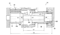
- Sectional drawing which shows the principal part of the gearbox of FIG.
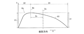
- the diagram which showed typically the formation mode of the crowning of the sun gear in the above-mentioned embodiment
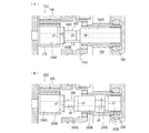
- Sectional drawing which shows the principal part of the gearbox for wind power generation which concerns on other embodiment of this invention.
- 1 shows a general crowning formation mode for a gear
- (A) is a perspective view
- (B) is a diagram corresponding to FIG. Front view showing an example of the overall configuration of a conventional (and the present invention) wind power generation facility
- the perspective view which shows the internal structure of the nacelle of the wind power generation facility of FIG.
- Sectional drawing which shows an example of the conventional gear box for wind power generation installed in the nacelle of the wind power generation equipment of FIG.
- FIG. 1 is an overall cross-sectional view of a speed increasing gear 50 for wind power generation showing an example of an embodiment of the present invention
- FIG. 2 is a cross-sectional view showing the main part thereof.
- the wind power speed increaser 50 includes a planetary gear mechanism 52 in the first stage and first and second parallel shaft gear mechanisms 54 and 56 in the middle stage and the rear stage.
- the rotation of the rotor head (similar to the conventional rotor head 4; see FIGS. 6 and 7) input from the input shaft 58 is accelerated by a total of three stages of gear mechanisms 52, 54 and 56 and output from the output shaft 60.
- the A generator (similar to the conventional generator 11: see FIG. 7) is connected to the output shaft 60, and predetermined power generation is performed.
- the planetary gear mechanism 52 includes a carrier 62 integrated with the input shaft 58, a planetary pin 64 that is supported at both ends by the carrier 62, and three planetary pins 64 that are rotatably supported by the planetary pin 64 via bearings 65 ( FIG. 2 shows only one planetary gear 68, the planetary gear 68 is internally meshed at the same time and is internally geared 70 fixed to the casing, and the planetary gear 68 is simultaneously circumscribedly meshed with the sun gear 72.
- the planetary gear 68, the internal gear 70, and the sun gear 72 are all configured as spur gears in this embodiment, but may be configured as helical gears.
- the rotation of the rotor head (4) by the wind force is input from the carrier 62 integrated with the input shaft 58, and the increased rotation is extracted from the output shaft 80 (of the planetary gear mechanism 52) integrated with the sun gear 72. It is configured.
- the output shaft 80 of the planetary gear mechanism 52 is directly (directly) used as the input shaft of the first parallel shaft gear mechanism 54, and the first helical gear 86 of the first parallel shaft gear mechanism 54 is connected via a spline 88. ing.
- the present invention is applied to a connection configuration between the planetary gear mechanism 52 and the first parallel shaft gear mechanism 54 (details will be described later).
- the first helical gear 86 meshes with the first helical pinion 90.
- the first helical gear 86 and the first helical pinion 90 constitute the first parallel shaft gear mechanism 54.
- the first helical pinion 90 is formed by cutting the second intermediate shaft 92 directly.
- a second helical gear 94 is connected to the second intermediate shaft 92 via a key 96 in the circumferential direction.
- the second helical gear 94 meshes with the second helical pinion 100.
- the second helical pinion 100 is formed by cutting directly on the output shaft 60 of the gear box 50.
- the second helical gear 94 and the second helical pinion 100 constitute a second parallel shaft gear mechanism 56.
- the output shaft 60 is rotatably supported by the casing 74 via bearings 103 and 105.
- the sun gear 72 of the planetary gear mechanism 52 is integrated with the output shaft 80 of the planetary gear mechanism 52. That is, the sun gear 72 and the output shaft 80 are manufactured by cutting the sun gear 72 from a single member.
- the output shaft 80 of the planetary gear mechanism 52 is directly used as the input shaft of the first parallel shaft gear mechanism 54 (without a coupling or the like).
- the output shaft 80 of the planetary gear mechanism 52 includes a sun gear forming portion 80A in which the sun gear 72 is formed, a first small diameter portion 80B, a second small diameter portion 80C formed continuously from the sun gear forming portion 80A, and A spline forming portion 80D in which the spline 88 is formed is provided.
- the root diameter of the sun gear forming portion 80A is d1
- the outer diameter d2 of the first small diameter portion 80B is smaller than the root diameter d1 of the sun gear forming portion 80A by 2 ⁇ ⁇ 1 (d1> d2).
- the outer diameter d3 of the second small diameter portion 80C is smaller by 2 ⁇ ⁇ 2 than the outer diameter d2 of the first small diameter portion 80B (d2> d3).
- the root diameter d4 of the spline forming portion 80D is larger by 2 ⁇ ⁇ 3 than the outer diameter d3 of the second small diameter portion 80C (d3 ⁇ d4). That is, the second small diameter portion 80C has a smaller diameter than the first small diameter portion 80B and the spline forming portion 80D on both sides thereof (d3 ⁇ d2, d3 ⁇ d4), and the axial length L1 is planetary. Coupled with occupying almost half of the axial length Lo of the entire output shaft 80 of the gear mechanism 52, a so-called “fragile portion” is formed.
- the sun gear 72 formed integrally with the output shaft 80 is subjected to crowning processing (tooth trace adjustment).
- crowning processing teeth trace adjustment
- the crowning process is performed “asymmetrically” with respect to the center Xc of the tooth trace direction.
- the broken line Ko in FIG. 3 is the original tooth trace shape (end surface shape in the width direction) of the sun gear 72 before the crowning process
- the solid line K1 is the tooth trace shape after the crowning process.
- the crowning process is performed so as to be symmetric with respect to the center Xc in the tooth trace direction X as shown in FIG.
- the shapes Ko and K2 before and after the crowning process in the tooth trace direction X are illustrated in FIG. 5B.
- the sun gear 72 of the present embodiment is a spur gear
- the tooth trace direction X coincides with the axial direction (tooth width direction) of the sun gear 72.
- the crowning amount is exaggerated with respect to the size of the tooth trace direction X. Taking big.
- the crowning is not the same as the center Xc in the tooth trace direction X. In contrast, it is applied "asymmetrically". Specifically, on the tooth surface of the sun gear 72, the portion Xm where the crowning is not performed is shifted by Xs from the center Xc in the tooth trace direction X of the sun gear 72 to the side opposite to the first parallel shaft gear mechanism. (The range X1 of the tooth trace direction X on the first parallel shaft gear mechanism side to be crowned is wider than the range X2 on the anti-first parallel shaft gear mechanism side).
- step-up gear 50 for wind power generation Next, the operation of the step-up gear 50 for wind power generation according to this embodiment will be described.
- Rotation of the windmill blade (5) is transmitted to the input shaft 58 of the speed increaser 50.
- the rotation of the input shaft 58 is input to the planetary gear mechanism 52 as the revolution of the planetary gear 68 through the carrier 62, and the rotation is accelerated by the relative rotation of the planetary gear 68, the internal gear 70, and the sun gear 72.
- the rotation of the output shaft 80 of the planetary gear mechanism 52 is directly transmitted to the first helical gear 86 of the first parallel shaft gear mechanism 54 via the spline 88.
- the rotation of the first helical gear 86 is transmitted to the first helical pinion 90, whereby the second intermediate shaft 92 rotates.
- the second intermediate shaft 92 rotates
- the second helical gear 94 rotates
- the output shaft 60 of the speed increaser 50 rotates through the second helical pinion 100 meshed with the second helical gear 94.
- the planetary gear mechanism 52 and the first parallel shaft gear mechanism 54 inevitably generate vibrations when the rotational torque is transmitted.
- the vibration of the planetary gear mechanism 52 and the vibration of the first parallel shaft gear mechanism 54 have different frequency characteristics (vibration waveforms) due to the difference in the rotation mechanism, the difference in the rotation speed, etc. Otherwise, they interfere with each other to generate resonance, and the vibration of the speed-up gear 50 as a whole is further amplified.
- the output shaft 80 of the planetary gear mechanism 52 has a second small diameter portion 80C having a diameter d3 smaller than the diameters d2 and d4 of both sides (the first small diameter portion 80B and the spline forming portion 80D). Therefore, the second small diameter portion 80C functions as a fragile portion and can absorb and block propagation of this vibration. For this reason, propagation of vibration between the planetary gear mechanism 52 and the first parallel shaft gear mechanism 54 is effectively suppressed, and the occurrence of resonance is suppressed. In particular, since vibration is prevented from propagating from the first parallel shaft gear mechanism 54 side to the planetary gear mechanism 52 side, the planetary gear 68 (the sun gear 72 and the internal gear 70 of the planetary gear mechanism 52). Smooth rotation and revolution are ensured, and in particular, the life of the bearing 65 can be extended.
- the present invention can have various variations.
- the small-diameter portion formed on the output shaft of the planetary gear mechanism (the input shaft of the parallel-shaft gear mechanism) is a single small-diameter portion that is long in the axial direction in the above embodiment.
- the basic configuration is the same as that of the above-described embodiment, and therefore, the corresponding two-digit code is attached to the corresponding portion for convenience.
- the axial length L2 of the second small diameter portion 180C of the output shaft 180 of the planetary gear mechanism 152 is shortened, and the second small diameter portion 180C is formed closer to the sun gear 172 side than the axial center 114C of the output shaft 180. ing.
- the small-diameter portion of the output shaft of the planetary gear mechanism may be formed at a plurality of locations in the axial direction of the output shaft.
- the output shaft 280 includes first and third small diameter portions 280B and 280D having an outer diameter d7 and a spline forming portion 280F, and a second small diameter portion having a smaller diameter (d8) than these. It has two small diameter portions, 280C and a fourth small diameter portion 280E.
- the second small diameter portion 280C and the fourth small diameter portion 280E have an outer diameter of d8, and the outer diameters d7 on both sides are larger and correspond to the “small diameter portion” of the present invention.
- the specific configuration of the small-diameter portion of the output shaft of the planetary gear mechanism is not particularly limited, and the magnitude of vibration to be absorbed, or The size, shape, number of formations, formation position, etc. may be set in consideration of frequency characteristics and the like.
- the output shaft of the planetary gear mechanism depends on how the small diameter portion is formed. Since the degree of swinging differs, it may be set in consideration of the degree of swinging.
- the concept of “crowning” of the present invention includes the concept of “end relief (relieving)”.
- the end relief is a processing method for releasing only both end portions of the gear in the tooth trace direction from the tooth contact, but is not a processing method deviating from the gist of the present invention.
- the end relief processing is applied to the present invention, it is a requirement that the range or size of the relief is not symmetrical with respect to the center of the tooth trace direction.
- the present invention can be used for a speed increaser of a wind power generation facility.
Landscapes
- Engineering & Computer Science (AREA)
- General Engineering & Computer Science (AREA)
- Mechanical Engineering (AREA)
- Life Sciences & Earth Sciences (AREA)
- Sustainable Development (AREA)
- Sustainable Energy (AREA)
- Chemical & Material Sciences (AREA)
- Combustion & Propulsion (AREA)
- Wind Motors (AREA)
- Retarders (AREA)
Abstract
小型、軽量、低コストでありながら、信頼性が高く、寿命の長い風力発電用の増速機を得る。風力発電用の増速機50において、太陽歯車72を有する遊星歯車機構52と、該遊星歯車機構52の後段に設けられた第1平行軸歯車機構54とを備え、前記遊星歯車機構52の前記太陽歯車72が該遊星歯車機構52の出力軸80に一体的に形成され、該遊星歯車機構52の前記出力軸80の軸方向の少なくとも1箇所が、その両側よりも径が小さな第2小径部80Cとされ、かつ、前記太陽歯車72の歯面が、該太陽歯車72の軸方向中央に対して非対称にクラウニングされている構成とする。
Description
本発明は、風力発電用の増速機に関する。
例えば特許文献1に、図6~図8に示されるような風力発電用の増速機が開示されている。
図6及び図7において、風力発電装置1は、基礎6上に立設される支柱2と、支柱2の上端に設置されるナセル3と、該ナセル3に対して回転自在に組付けられたロータヘッド4とを有している。ロータヘッド4は、複数枚(図示の例では3枚)の風車ブレード(風車翼)5が取り付けられている。ナセル3の内部において、ロータヘッド4には、増速機20及び発電機11が接続されている。
風車ブレード5に風が当たると、ロータヘッド4が回転し、該ロータヘッド4の回転が増速機20にて増速した状態で発電機11に伝達される。これにより、ロータヘッド4の(トルクはあるが)速度が遅い回転を、100倍程度の速さに増幅することができ、発電機11から効率的に発電出力を得ることができる。
前記増速機20は、図8に示すように、初段に遊星歯車機構22を備えると共に、中段及び後段に平行軸歯車機構24、26を備える。初段の遊星歯車機構22は、入力軸28と一体化されたキャリヤ32、該キャリヤ32に固定された遊星ピン34、該遊星ピン34に回転自在に支持された遊星歯車36、該遊星歯車36が同時に噛合する内歯歯車38及び太陽歯車40から主に構成されている。この従来例に係る遊星歯車機構22は、キャリヤ32から入力された回転を太陽歯車40から出力する。該太陽歯車40は、遊星歯車機構22の出力軸42と一体化されている。出力軸42は、カップリング43を介して次段の平行軸歯車機構24の入力軸45と連結されている。
増速機20の遊星歯車機構22及び平行軸歯車機構24、26の各歯車機構によって増速された回転が、前記発電機11に入力される。
なお、図7に示す符号12はトランス、13はコントローラ、14はインバータ、15はインバータクーラ、16は潤滑油クーラである。
風力発電設備は、その耐用期間が20年前後となるように設計される。このため、増速機についても基本的に20年前後の寿命が確保されることが要求される。
しかしながら、風力発電設備は、自然環境下に設置される設備であるため、ときに乱れた風や突風を受けたりすることがある。このような強い風が風車ブレードに掛かると増速機は入力側から巨大な負荷が掛けられた状態となってしまう。このため、(たとえガイドラインに沿った設計がなされている場合であっても)増速機内の各部が過度に速い回転速度で強制的に回転させられる状態が発生してしまい、トラブルの原因となることがあった。
増速機のトラブルは、一度発生するとその被害は深刻なものとなるため、信頼性の確保が重要視されている。一般に、増速機の信頼性を確保するにあたって有効な対策は、設計時に各要素の安全率(セーフティファクタ)を大きくとることである。しかし、各要素の安全率を大きくとると、当然に増速機全体が大型化して重量も大きくなり、製造コスト、建設コストの増大を招くという問題が生じる。
本発明は、このような問題を解消するためになされたものであって、新たに見つけた「中間課題(後述)」を克服することによって、小型、軽量、低コストでありながら、信頼性が高く、寿命の長い風力発電用の増速機を提供することをその本来の課題としている。
本発明は、風力発電用の増速機において、太陽歯車を有する遊星歯車機構と、該遊星歯車機構の後段に設けられた平行軸歯車機構とを備え、前記遊星歯車機構の前記太陽歯車が、該遊星歯車機構の出力軸に一体的に形成され、該遊星歯車機構の前記出力軸の軸方向の少なくとも1箇所が、その両側よりも径が小さな小径部とされ、かつ、前記太陽歯車の歯面が、該太陽歯車の歯筋方向中央に対して非対称にクラウニングされている構成とすることにより、上記課題を解決したものである。
本発明の前記中間課題及びその解決原理は、公知のものではないため、ここで、本発明が着目した当該中間課題とその解決原理について、詳細に説明する。
風力発電設備の風車ブレードに、風が当たると、これに伴って増速機の各部に回転トルクが発生する。増速機内の遊星歯車機構や平行軸歯車機構が該回転トルクを伝達する際には、不可避的に振動が発生する。しかしながら、遊星歯車機構と平行軸歯車機構とでは、回転のメカニズムも回転速度も異なることから、発生する振動の特性(周波数成分等)がそれぞれ異なる。このため、入力されてくる風の強さや脈動の仕方によっては、これらの振動が相互に干渉し合って共振が発生してしまうことがある。この結果、特に軸受部において、本来転がり接触であったころ(またはボール)と内輪、外輪等が滑りを起こすようになり、それによりピッチング等の耐久性を低下させる症状が発生し易くなる。
本発明は、遊星歯車機構と平行軸歯車機構との共振の発生を極力抑制することを「中間課題」として捉え、かつ、この中間課題を解消するために採用した構成が、新たな不具合を発生しないように更なる工夫を施すことによって創案された。
本発明に係る風力発電用の増速機では、遊星歯車機構の太陽歯車は、該遊星歯車機構の出力軸と一体的に形成される。ここで言う「一体的に形成」とは、キーやスプライン等を介して2つの部材(太陽歯車部材と出力軸部材)を連結して結果として一体化するのではなく、太陽歯車と出力軸とが初めから一つの部材として一体化されていることを意味している。
その上で、本発明では、該遊星歯車機構の出力軸の軸方向の少なくとも1箇所が、その両側よりも径が小さな小径部とされる。この構成により、該小径部の存在によって該遊星歯車機構の出力軸の一部が意図的に脆弱化され、遊星歯車機構と平行軸歯車機構のそれぞれの振動の伝播をここで吸収・遮断することができる。
しかも、本発明では、さらに、太陽歯車の歯面が、該太陽歯車の歯筋方向中央に対して非対称にクラウニングされる構成が同時に採用されている。このため、仮に遊星歯車機構の出力軸の一部が脆弱化されたが故に該出力軸が多少振れ廻ってその軸心が傾いたとしても、太陽歯車と遊星歯車との間で良好な歯当たりを常に維持することができる。したがって、遊星歯車機構の太陽歯車の回転や遊星歯車の公転等を極めて安定した状態で行わせることができ、特に(遊星歯車の軸受を含む)各軸受の寿命をより伸ばすことができるようになる。
本発明によれば、小型、軽量、低コストでありながら、信頼性が高く、寿命の長い風力発電用の増速機を得ることが可能となる。
以下、図面に基づいて本発明の実施形態の一例を詳細に説明する。
本発明に係る増速機が組み込まれる風力発電設備の概略構成については、既に図6、図7を用いて説明したものと同様であるため、重複説明は省略し、以降、増速機自体の構成について詳細にする。
図1は、本発明の実施形態の一例を示す風力発電用の増速機50の全体断面図、図2は、その主要部を示す断面図である。
先ず、図1を参照して、この風力発電用の増速機50は、初段に遊星歯車機構52を備えると共に、中段及び後段に第1、第2平行軸歯車機構54、56を備える。入力軸58から入力されるロータヘッド(従来のロータヘッド4と同様:図6、7参照)の回転は、計3段の歯車機構52、54、56によって増速され、出力軸60から出力される。出力軸60には、発電機(従来の発電機11と同様:図7参照)が連結され、所定の発電がなされる。
前記遊星歯車機構52は、入力軸58と一体化されたキャリヤ62、該キャリヤ62に両持ち支持された遊星ピン64、該遊星ピン64に軸受65を介して回転自在に支持された3個(図2では1個のみ図示)の遊星歯車68、該遊星歯車68が同時に内接噛合すると共にケーシングに固定された内歯歯車70、及び遊星歯車68が同時に外接噛合する太陽歯車72から構成されている。これらの遊星歯車68、内歯歯車70、及び太陽歯車72は、この実施形態ではいずれも平歯車で構成されているが、ヘリカル歯車で構成しても良い。
風力によるロータヘッド(4)の回転は、入力軸58と一体化されたキャリヤ62から入力され、太陽歯車72と一体の(遊星歯車機構52の)出力軸80から増速された回転が取り出される構成とされている。遊星歯車機構52の出力軸80は、そのまま(直接)第1平行軸歯車機構54の入力軸とされており、該第1平行軸歯車機構54の第1ヘリカルギヤ86がスプライン88を介して連結されている。
本発明は、このうちの遊星歯車機構52と第1平行軸歯車機構54との間の連結構成に適用されている(後に詳述)。
第1ヘリカルギヤ86は第1ヘリカルピニオン90と噛合している。第1ヘリカルギヤ86と第1ヘリカルピニオン90が第1平行軸歯車機構54を構成している。
第1ヘリカルピニオン90は第2中間軸92に直切り形成されている。第2中間軸92には第2ヘリカルギヤ94がキー96を介して円周方向に連結されている。第2ヘリカルギヤ94は第2ヘリカルピニオン100と噛合している。第2ヘリカルピニオン100は当該増速機50の出力軸60に直切り形成されている。第2ヘリカルギヤ94と第2ヘリカルピニオン100が第2平行軸歯車機構56を構成している。出力軸60は、軸受103、105を介してケーシング74により回転自在に支持されている。
以下、主に図2を参照して、遊星歯車機構52と第1平行軸歯車機構54との連結部付近の構成について詳細に説明する。
前述したように、本実施形態においては、遊星歯車機構52の太陽歯車72は該遊星歯車機構52の出力軸80と一体化されている。すなわち、太陽歯車72と出力軸80は、単一の部材から太陽歯車72を切削形成することによって製造されている。遊星歯車機構52の出力軸80は、(カップリング等を介することなく)そのまま「直接」第1平行軸歯車機構54の入力軸とされている。
遊星歯車機構52の出力軸80は、太陽歯車72が形成されている太陽歯車形成部80A、該太陽歯車形成部80Aから連続して形成された第1小径部80B、第2小径部80C、及び前記スプライン88が形成されているスプライン形成部80Dを備える。太陽歯車形成部80Aの歯底円径はd1であり、第1小径部80Bの外径d2は該太陽歯車形成部80Aの歯底円径d1より2・Δ1だけ小さい(d1>d2)。また、第2小径部80Cの外径d3は、該第1小径部80Bの外径d2よりも更に2・Δ2だけ小さい(d2>d3)。また、スプライン形成部80Dの歯底円径d4は、第2小径部80Cの外径d3より2・Δ3だけ大きい(d3<d4)。すなわち、第2小径部80Cは、その両側の第1小径部80B及びスプライン形成部80Dよりも小さな径とされており(d3<d2、d3<d4)、かつ、その軸方向長さL1が遊星歯車機構52の出力軸80全体の軸方向長さLoのほぼ半分を占めていることと相まって、いわゆる「脆弱部」を形成している。
一方、出力軸80に一体形成されている太陽歯車72には、クラウニング処理(歯筋調整)がなされている。この実施形態では、図3に示されるように、該クラウニング処理を歯筋方向中央Xcに対して「非対称」に施すようにしている。図3の破線Koがクラウニング処理をする前の太陽歯車72のもともとの歯筋形状(幅方向の端面形状)、実線K1がクラウニング処理をした後の歯筋形状である。一般に、歯車の歯面に対してクラウニング処理を施すときには、図5(A)に示されるように、歯筋方向Xの中央Xcに対して対称となるように、クラウニング処理がなされる。すなわち、歯筋方向Xにおけるクラウニング処理前後の形状Ko、K2を図示すると、図5(B)のようになっている。なお、本実施形態の太陽歯車72は、平歯車であるため、歯筋方向Xは、太陽歯車72の軸方向(歯幅方向)に一致している。なお、これらクラウニング処理の形状描写は、歯筋方向Xにおけるクラウニング処理(クラウニング量)の定性的な傾向を理解し易くするため、歯筋方向Xの大きさに対しクラウニング量を誇張して非常に大きく取っている。
図3の本実施形態の説明に戻って、本実施形態では、(このように歯筋方向Xの中央Xcに対して対称にクラウニングを施すのではなく)該クラウニングを歯筋方向Xの中央Xcに対して「非対称」に施すようにしている。具体的には、太陽歯車72の歯面において、クラウニングの最もなされていない部分Xmが、該太陽歯車72の歯筋方向Xの中央Xcより反第1平行軸歯車機構側にXsだけずれている(クラウニング処理される第1平行軸歯車機構側の歯筋方向Xの範囲X1が、反第1平行軸歯車機構側の範囲X2よりも広範囲)。なお、この実施形態では、太陽歯車72の歯筋方向端面における第1平行軸歯車機構側のクラウニング量δ1と、反第1平行軸歯車機構側のクラウニング量δ2は、同一である(δ1=δ2)。このため、結果として、第1平行軸歯車機構54側の方が、反第1平行軸歯車機構側よりなだらかなクラウニング処理となっている。
次に、この実施形態に係る風力発電用の増速機50の作用を説明する。
風車ブレード(5)の回転は、増速機50の入力軸58に伝達される。入力軸58の回転はキャリヤ62を介して遊星歯車68の公転として遊星歯車機構52に入力され、遊星歯車68、内歯歯車70、太陽歯車72の3者の相対回転により、増速された回転が太陽歯車72と一体化された(遊星歯車機構52の)出力軸80へと出力される。
遊星歯車機構52の出力軸80の回転は、スプライン88を介してそのまま第1平行軸歯車機構54の第1ヘリカルギヤ86に伝達される。第1ヘリカルギヤ86の回転は、第1ヘリカルピニオン90に伝達され、これにより第2中間軸92が回転する。第2中間軸92が回転すると、第2ヘリカルギヤ94が回転し、該第2ヘリカルギヤ94と噛合している第2ヘリカルピニオン100を介して増速機50の出力軸60が回転する。
ここで、遊星歯車機構52及び第1平行軸歯車機構54の連結部付近において、以下のような作用がなされる。
即ち、入力軸58から回転トルクが入力されてくると、該回転トルクが伝達される際に遊星歯車機構52及び第1平行軸歯車機構54では不可避的に振動が発生する。遊星歯車機構52の振動と第1平行軸歯車機構54の振動は、回転のメカニズムの違い、及び回転速度の違い等からそれぞれの周波数特性(振動の波形)が異なるため、(何らの対策も施さないと)互いに干渉して共振が発生してしまい、増速機50全体の振動がより増幅されてしまう。明確な共振が発生しないまでも、特に高速回転している第1平行軸歯車機構54側から遊星歯車機構52側に該高速回転の振動が伝播すると、遊星歯車機構52の遊星歯車68の(太陽歯車72及び内歯歯車70の間での)円滑な回転及び公転が損なわれ、特に軸受65の寿命に影響する恐れがある。
しかしながら、この実施形態では、遊星歯車機構52の出力軸80に、その両側(第1小径部80B及びスプライン形成部80D)の径d2、d4よりも小径の径d3を有する第2小径部80Cが存在しているため、この第2小径部80Cが脆弱部として機能してこの振動の伝播を吸収・遮断することができる。このため、遊星歯車機構52と、第1平行軸歯車機構54との間の振動の伝播が効果的に抑制され、共振の発生が抑制される。また、とりわけ第1平行軸歯車機構54側から遊星歯車機構52側に振動が伝搬されるのが防止されるため、該遊星歯車機構52の遊星歯車68の(太陽歯車72及び内歯歯車70の間での)円滑な回転及び公転が確保され、特に軸受65の寿命を延ばすことができる。
本発明は、様々なバリエーションが考えられる。
まず、遊星歯車機構の出力軸(平行軸歯車機構の入力軸)に形成される小径部は、前記実施形態においては、軸方向に長い単一の小径部とされていたが、例えば、図4(A)に示すように変形しても良い。図4(A)に示す変形例では、基本的な構成は、前記実施形態と同様であるため、便宜上対応する部位に同一末尾2桁の符号を付している。遊星歯車機構152の出力軸180の第2小径部180Cの軸方向長L2を短くし、該第2小径部180Cを、出力軸180の軸方向中央114Cよりも太陽歯車172側に形成するようにしている。このような構成とすることにより、(スプライン188で第1ヘリカルギヤ186と連結されている)出力軸180の第1平行軸歯車機構側の振れ廻りを最小限に抑えつつ、遊星歯車機構152側の振れ廻りを太陽歯車172のクラウニングによって効果的に吸収するようにしている。
また、図4(B)のように、遊星歯車機構の出力軸の小径部は、該出力軸の軸方向複数箇所に形成するようにしてもよい。図4(B)の例では、出力軸280が、外径がd7の第1、第3小径部280B、280D、及びスプライン形成部280Fを備えると共に、これらより小径(d8)の第2小径部280C及び第4小径部280Eの2つの小径部を有している。このうち、第2小径部280C及び第4小径部280Eは、自身の外径がd8で、それぞれの両側の外径d7の方が大きく、本発明の「小径部」に相当している。図4(B)のように複数の小径部を形成するようにすると、脆弱性をより効果的に機能させることができ、振動の伝播抑制効果をより高めることができる。
このように、本発明では、遊星歯車機構の出力軸の小径部を具体的にどのような構成で形成するかについては、特に限定されるものではなく、吸収しようとする振動の大きさ、或いは周波数特性等を考慮してその大きさ、形状、形成数、或いは形成位置等を設定すればよい。
また、太陽歯車のクラウニング処理におけるクラウニング量の具体的な大きさ、或いは形状(例えば、歯筋方向中央からどの程度非対称とするか)についても、小径部の形成の仕方によって遊星歯車機構の出力軸の振れ廻り程度が異なってくるため、該振れ廻りの程度を考慮して設定すればよい。
なお、本発明の「クラウニング」の概念には、「エンドレリーフ(レリービング)」の概念が含まれる。エンドレリーフとは、歯車の歯筋方向の両端部のみを歯当たりから逃がす処理方法であるが、本発明の趣旨から逸脱する処理方法ではない。エンドレリーフ処理を本発明に適用する場合には、レリービングの範囲或いは大きさが、歯筋方向中央に対して対称でないことが要件となる。
本発明は、風力発電設備の増速機に利用可能である。
2011年3月23日に出願された日本国出願番号2011-063892の明細書、図面及び特許請求の範囲における開示は、その全体がこの明細書中に参照により援用されている。
1…風力発電設備
3…ナセル
4…ロータヘッド
5…風車ブレード
11…発電機
50…増速機
52…遊星歯車機構
54…第1平行軸歯車機構
56…第2平行軸歯車機構
58…入力軸
60…出力軸
80、180、280…遊星歯車機構の出力軸(第1平行軸歯車機構の入力軸)
3…ナセル
4…ロータヘッド
5…風車ブレード
11…発電機
50…増速機
52…遊星歯車機構
54…第1平行軸歯車機構
56…第2平行軸歯車機構
58…入力軸
60…出力軸
80、180、280…遊星歯車機構の出力軸(第1平行軸歯車機構の入力軸)
Claims (4)
- 風力発電用の増速機において、
太陽歯車を有する遊星歯車機構と、該遊星歯車機構の後段に設けられた平行軸歯車機構とを備え
前記遊星歯車機構の前記太陽歯車が該遊星歯車機構の出力軸に一体的に形成され、
該遊星歯車機構の前記出力軸の軸方向の少なくとも1箇所が、その両側よりも径が小さな小径部とされ、かつ、
前記太陽歯車の歯面が、該太陽歯車の歯筋方向中央に対して非対称にクラウニングされている
ことを特徴とする風力発電用の増速機。 - 請求項1において、
前記小径部が、前記遊星歯車機構の出力軸の軸方向複数箇所に形成されている
ことを特徴とする風力発電用の増速機。 - 請求項1または2において、
前記小径部が、前記遊星歯車機構の出力軸の軸方向中央より前記太陽歯車側に形成されている
ことを特徴とする風力発電用の増速機。 - 請求項1~3のいずれかにおいて、
前記太陽歯車の歯面において、前記クラウニングの最もなされていない部分が、該太陽歯車の歯筋方向中央より、反平行軸歯車機構側にずれている
ことを特徴とする風力発電用の増速機。
Priority Applications (1)
| Application Number | Priority Date | Filing Date | Title |
|---|---|---|---|
| CN2011800651219A CN103370537A (zh) | 2011-03-23 | 2011-11-21 | 风力发电用增速器 |
Applications Claiming Priority (2)
| Application Number | Priority Date | Filing Date | Title |
|---|---|---|---|
| JP2011-063892 | 2011-03-23 | ||
| JP2011063892A JP2012197773A (ja) | 2011-03-23 | 2011-03-23 | 風力発電用の増速機 |
Publications (1)
| Publication Number | Publication Date |
|---|---|
| WO2012127736A1 true WO2012127736A1 (ja) | 2012-09-27 |
Family
ID=46878924
Family Applications (1)
| Application Number | Title | Priority Date | Filing Date |
|---|---|---|---|
| PCT/JP2011/076769 Ceased WO2012127736A1 (ja) | 2011-03-23 | 2011-11-21 | 風力発電用の増速機 |
Country Status (3)
| Country | Link |
|---|---|
| JP (1) | JP2012197773A (ja) |
| CN (1) | CN103370537A (ja) |
| WO (1) | WO2012127736A1 (ja) |
Cited By (2)
| Publication number | Priority date | Publication date | Assignee | Title |
|---|---|---|---|---|
| CN108506427A (zh) * | 2018-05-31 | 2018-09-07 | 福州大学 | 一种适用于大功率传动的增速器及其工作方法 |
| US10335797B2 (en) | 2013-07-08 | 2019-07-02 | Flsmidth A/S | Heavy duty drive arrangement and mill |
Families Citing this family (2)
| Publication number | Priority date | Publication date | Assignee | Title |
|---|---|---|---|---|
| JP5938359B2 (ja) * | 2013-02-28 | 2016-06-22 | 住友重機械工業株式会社 | 風力発電設備に使用する減速装置 |
| CN114655024B (zh) * | 2019-12-26 | 2024-03-22 | 株式会社爱信 | 车用驱动装置 |
Citations (4)
| Publication number | Priority date | Publication date | Assignee | Title |
|---|---|---|---|---|
| JP2005023978A (ja) * | 2003-06-30 | 2005-01-27 | Mitsubishi Heavy Ind Ltd | はすば歯車及びこれを用いた風車用増速機 |
| JP2005233277A (ja) * | 2004-02-18 | 2005-09-02 | Komatsu Ltd | 遊星歯車装置の歯車締結構造 |
| JP2007525623A (ja) * | 2003-11-20 | 2007-09-06 | ハンセン・トランスミッションズ・インターナショナル・ナムローゼフェンノートシャップ | 遊星歯車装置を備える歯車伝動装置 |
| JP2010270911A (ja) * | 2009-05-20 | 2010-12-02 | Hansen Transmissions Internatl Nv | 遊星歯車伝動ユニット |
-
2011
- 2011-03-23 JP JP2011063892A patent/JP2012197773A/ja not_active Withdrawn
- 2011-11-21 CN CN2011800651219A patent/CN103370537A/zh active Pending
- 2011-11-21 WO PCT/JP2011/076769 patent/WO2012127736A1/ja not_active Ceased
Patent Citations (4)
| Publication number | Priority date | Publication date | Assignee | Title |
|---|---|---|---|---|
| JP2005023978A (ja) * | 2003-06-30 | 2005-01-27 | Mitsubishi Heavy Ind Ltd | はすば歯車及びこれを用いた風車用増速機 |
| JP2007525623A (ja) * | 2003-11-20 | 2007-09-06 | ハンセン・トランスミッションズ・インターナショナル・ナムローゼフェンノートシャップ | 遊星歯車装置を備える歯車伝動装置 |
| JP2005233277A (ja) * | 2004-02-18 | 2005-09-02 | Komatsu Ltd | 遊星歯車装置の歯車締結構造 |
| JP2010270911A (ja) * | 2009-05-20 | 2010-12-02 | Hansen Transmissions Internatl Nv | 遊星歯車伝動ユニット |
Cited By (2)
| Publication number | Priority date | Publication date | Assignee | Title |
|---|---|---|---|---|
| US10335797B2 (en) | 2013-07-08 | 2019-07-02 | Flsmidth A/S | Heavy duty drive arrangement and mill |
| CN108506427A (zh) * | 2018-05-31 | 2018-09-07 | 福州大学 | 一种适用于大功率传动的增速器及其工作方法 |
Also Published As
| Publication number | Publication date |
|---|---|
| JP2012197773A (ja) | 2012-10-18 |
| CN103370537A (zh) | 2013-10-23 |
Similar Documents
| Publication | Publication Date | Title |
|---|---|---|
| JP5493079B2 (ja) | 遊星ギヤ装置の構成、および遊星ギヤ | |
| ES2587020T3 (es) | Una turbina eólica con un tren de transmisión | |
| KR101134961B1 (ko) | 변속 장치 및 풍력 발전 장치 | |
| JP5622716B2 (ja) | 遊星歯車装置および風力発電装置 | |
| WO2011027427A1 (ja) | 風力発電装置 | |
| WO2012127736A1 (ja) | 風力発電用の増速機 | |
| CN101849105B (zh) | 用于风力涡轮机齿轮箱的行星齿轮级、风力涡轮机齿轮箱和风力涡轮机 | |
| JP5654949B2 (ja) | 風力発電設備の動力伝達装置 | |
| RU2659196C1 (ru) | Сдвоенная волновая зубчатая передача | |
| JP5148346B2 (ja) | 風力発電装置 | |
| JP6711653B2 (ja) | 風車の可動部位を駆動する駆動装置及び風車 | |
| JP5180871B2 (ja) | 多段式遊星歯車変速装置 | |
| JP2010216562A (ja) | 自然エネルギの回収システム用の減速装置 | |
| JP5352510B2 (ja) | 風力発電用の増速機 | |
| JP4195643B2 (ja) | はすば歯車及びこれを用いた風車用増速機 | |
| CN112081896A (zh) | 一种谐波减速器 | |
| JP5832206B2 (ja) | 風力発電用の増速機 | |
| JP6138012B2 (ja) | 風力発電設備のヨー駆動システム | |
| JP2010216591A (ja) | 減速装置 | |
| JP5676293B2 (ja) | 風力発電用の増速機 | |
| CN219317562U (zh) | 齿轮箱及风力发电机组 | |
| JP2010144883A (ja) | 動力伝達装置 | |
| CN103335012A (zh) | 一种风电齿轮箱的太阳齿轮轴 | |
| CN219119729U (zh) | 一种齿圈与主轴轴承座浮动连接的风电齿轮箱 | |
| JP2006249982A (ja) | 風力発電装置 |
Legal Events
| Date | Code | Title | Description |
|---|---|---|---|
| 121 | Ep: the epo has been informed by wipo that ep was designated in this application |
Ref document number: 11861746 Country of ref document: EP Kind code of ref document: A1 |
|
| NENP | Non-entry into the national phase |
Ref country code: DE |
|
| 122 | Ep: pct application non-entry in european phase |
Ref document number: 11861746 Country of ref document: EP Kind code of ref document: A1 |