WO2012127684A1 - ラック及びケーブルマネージメント装置 - Google Patents
ラック及びケーブルマネージメント装置 Download PDFInfo
- Publication number
- WO2012127684A1 WO2012127684A1 PCT/JP2011/057199 JP2011057199W WO2012127684A1 WO 2012127684 A1 WO2012127684 A1 WO 2012127684A1 JP 2011057199 W JP2011057199 W JP 2011057199W WO 2012127684 A1 WO2012127684 A1 WO 2012127684A1
- Authority
- WO
- WIPO (PCT)
- Prior art keywords
- cable
- rack
- cable holding
- holding bar
- support arm
- Prior art date
Links
Images


Classifications
-
- H—ELECTRICITY
- H02—GENERATION; CONVERSION OR DISTRIBUTION OF ELECTRIC POWER
- H02G—INSTALLATION OF ELECTRIC CABLES OR LINES, OR OF COMBINED OPTICAL AND ELECTRIC CABLES OR LINES
- H02G11/00—Arrangements of electric cables or lines between relatively-movable parts
-
- H—ELECTRICITY
- H02—GENERATION; CONVERSION OR DISTRIBUTION OF ELECTRIC POWER
- H02G—INSTALLATION OF ELECTRIC CABLES OR LINES, OR OF COMBINED OPTICAL AND ELECTRIC CABLES OR LINES
- H02G3/00—Installations of electric cables or lines or protective tubing therefor in or on buildings, equivalent structures or vehicles
- H02G3/02—Details
- H02G3/04—Protective tubing or conduits, e.g. cable ladders or cable troughs
- H02G3/0456—Ladders or other supports
-
- H—ELECTRICITY
- H02—GENERATION; CONVERSION OR DISTRIBUTION OF ELECTRIC POWER
- H02G—INSTALLATION OF ELECTRIC CABLES OR LINES, OR OF COMBINED OPTICAL AND ELECTRIC CABLES OR LINES
- H02G3/00—Installations of electric cables or lines or protective tubing therefor in or on buildings, equivalent structures or vehicles
- H02G3/26—Installations of cables, lines, or separate protective tubing therefor directly on or in walls, ceilings, or floors
- H02G3/263—Installation, e.g. suspension, of conduit channels or other supports
-
- H—ELECTRICITY
- H02—GENERATION; CONVERSION OR DISTRIBUTION OF ELECTRIC POWER
- H02G—INSTALLATION OF ELECTRIC CABLES OR LINES, OR OF COMBINED OPTICAL AND ELECTRIC CABLES OR LINES
- H02G3/00—Installations of electric cables or lines or protective tubing therefor in or on buildings, equivalent structures or vehicles
- H02G3/30—Installations of cables or lines on walls, floors or ceilings
-
- H—ELECTRICITY
- H02—GENERATION; CONVERSION OR DISTRIBUTION OF ELECTRIC POWER
- H02G—INSTALLATION OF ELECTRIC CABLES OR LINES, OR OF COMBINED OPTICAL AND ELECTRIC CABLES OR LINES
- H02G3/00—Installations of electric cables or lines or protective tubing therefor in or on buildings, equivalent structures or vehicles
- H02G3/36—Installations of cables or lines in walls, floors or ceilings
- H02G3/38—Installations of cables or lines in walls, floors or ceilings the cables or lines being installed in preestablished conduits or ducts
- H02G3/383—Installations of cables or lines in walls, floors or ceilings the cables or lines being installed in preestablished conduits or ducts in floors
-
- H—ELECTRICITY
- H04—ELECTRIC COMMUNICATION TECHNIQUE
- H04Q—SELECTING
- H04Q1/00—Details of selecting apparatus or arrangements
- H04Q1/02—Constructional details
- H04Q1/06—Cable ducts or mountings specially adapted for exchange installations
-
- H—ELECTRICITY
- H04—ELECTRIC COMMUNICATION TECHNIQUE
- H04Q—SELECTING
- H04Q1/00—Details of selecting apparatus or arrangements
- H04Q1/02—Constructional details
- H04Q1/09—Frames or mounting racks not otherwise provided for
-
- H—ELECTRICITY
- H05—ELECTRIC TECHNIQUES NOT OTHERWISE PROVIDED FOR
- H05K—PRINTED CIRCUITS; CASINGS OR CONSTRUCTIONAL DETAILS OF ELECTRIC APPARATUS; MANUFACTURE OF ASSEMBLAGES OF ELECTRICAL COMPONENTS
- H05K7/00—Constructional details common to different types of electric apparatus
- H05K7/14—Mounting supporting structure in casing or on frame or rack
- H05K7/1485—Servers; Data center rooms, e.g. 19-inch computer racks
- H05K7/1488—Cabinets therefor, e.g. chassis or racks or mechanical interfaces between blades and support structures
- H05K7/1491—Cabinets therefor, e.g. chassis or racks or mechanical interfaces between blades and support structures having cable management arrangements
Definitions
- the present invention relates to a rack for accommodating a plurality of electronic devices and a cable management device accommodated in the rack.
- a plurality of electronic devices (computer devices, communication devices, etc.) are accommodated in each of a plurality of racks.
- cables related to each electronic device in the rack have been accommodated under the floor, but in recent years, cables related to each electronic device have been accommodated separately under the floor and the ceiling side. ing.
- FIGS. 2A and 2B if a cable rack is provided on the ceiling of a server room or the like so that cables from each rack are accommodated separately under the floor and the ceiling side, air conditioning is provided under the floor. Space for supplying cold air from the machine can be secured. Moreover, it is possible to prevent a large amount of cables from being present in the lower part of each rack (to make the connection form of cables to each rack orderly). Therefore, cables from each rack are accommodated separately under the floor and the ceiling.
- FIGS. 3A and 3B show a state in which cables are simply connected to each electronic device in the rack.
- the cables are likely to be tangled.
- the cable may get in the way. Therefore, a device called a cable management arm and having the configuration shown in FIGS. 3A and 3B is commercially available.
- it is an arm-like device with multiple joints that is fixed to the electronic device and the rack, and if the cable is fixed with a hook-and-loop fastener along the cable, it can be Devices that can prevent cable entanglement are commercially available.
- cables related to each rack are accommodated separately under the floor and on the ceiling side.
- cables are also accommodated on the ceiling side, some electronic devices in the rack are used. The maintenance work becomes difficult.
- the work target device when maintenance work is performed on electronic devices in a rack in a data center or the like, it may be necessary to remove a cable from the electronic device that is the maintenance work target (hereinafter referred to as the work target device).
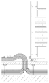
- the work target device in a data center or the like in which all the cables from the rack are accommodated under the floor, it is only necessary to remove the cables from the work target device and several electronic devices located above it. This is because, when each cable is accommodated under the floor, as schematically shown in FIGS. 4A and 4B, if the cable removed from the work target device is placed on the floor surface, the back side of the work target device This is because there is no cable that obstructs the work.
- the cable is removed from the electronic device (in the figure, the uppermost electronic device; hereinafter referred to as a work target device). It hangs down from above with its own weight.
- cables removed from the second to sixth stages of electronic devices also hang down from above due to their own weight.
- the maintenance work for the above-mentioned work target device is performed after scraping the cable hanging from above by its own weight, or bundling the cables removed from some electronic devices and standing by the side.
- it is difficult to work while scraping the cables.
- the operation of bundling cables is complicated, and there are cases where there is no fixed portion for the bundled cables.
- an object of the disclosed technique is to provide a rack and a cable management device that can easily perform maintenance work of an electronic device connected to a cable from the ceiling side by using it.
- a rack main body that houses a plurality of electronic devices arranged in the vertical direction;
- a plurality of cable holding bars that are respectively fixed to any of a plurality of fixing members that are pivotally supported by a rotating shaft provided in the rack body so as to be pivotable in the vertical direction, and extend in the axial direction of the rotating shaft;
- Each of the plurality of fixing members fixes the cable holding bar when the cable holding bar is fixed so that the distance between the fixing cable holding bar and the rotation shaft is different from each other, and the cable holding bar is rotated upward.
- the holding member and the rotation shaft have a shape in which both the fixing members whose length is longer than themselves are rotated upward.
- a cable management device for a rack that accommodates a plurality of electronic devices arranged in the vertical direction according to an aspect of the disclosed technology
- a housing having a shape that can be accommodated in a rack
- a cable management assembly attached to the housing so as to be housed in and removable from the housing
- Cable management assembly A plurality of fixing members that are rotatable with respect to a rotation shaft provided in the housing;
- a plurality of cable holding bars fixed to any of the fixing members and extending in the axial direction of the rotating shaft;
- Each of the fixing members has a different distance between the cable holding bar and the rotating shaft to be fixed to each other, and when the cable holding bar is rotated upward, the distance between the cable holding bar and the rotating shaft is longer than that of the fixing member.
- the fixing member also has a shape / positional relationship for rotating together.
- FIG. 1 is a diagram schematically illustrating a state in which cables relating to the respective electronic devices in the rack are accommodated under the floor.
- FIG. 2A is a diagram schematically illustrating a state in which cables relating to the respective electronic devices in the rack are accommodated separately under the floor and on the ceiling side.
- FIG. 2B is a diagram schematically illustrating a state in which cables relating to the respective electronic devices in the rack are accommodated separately under the floor and on the ceiling side.
- FIG. 3A is an explanatory diagram of a cable management arm.
- FIG. 3B is an explanatory diagram of the cable management arm.
- FIG. 4A is a diagram schematically illustrating a state in which a rack in which cables relating to each electronic device are accommodated under the floor is in a maintenance operation of the electronic device.
- FIG. 4B is a diagram schematically illustrating a state in which a rack in which cables related to the respective electronic devices are stored under the floor is in a maintenance operation of the electronic devices.
- FIG. 5A is a diagram schematically showing a state during maintenance work of an electronic device to which a cable from the ceiling side is connected.
- FIG. 5B is a diagram schematically illustrating a state during maintenance work of the electronic device to which the cable from the ceiling side is connected.
- FIG. 6 is a rear view of a rack (having electronic devices accommodated and cables connected) according to the first embodiment of the present invention.
- FIG. 7 is a side view of the rack according to the first embodiment.
- FIG. 8 is a partially exploded perspective view of the cable management assembly according to the first embodiment (the cable management assembly provided in the rack according to the first embodiment).
- FIG. 9 is a partial perspective view of the cable management assembly according to the first embodiment.
- FIG. 10 is a partial projection view from the distal end side of the support arm of the cable management assembly according to the first embodiment in a state where the support arms overlap each other.
- FIG. 11 is an explanatory diagram of the cable management assembly according to the first embodiment.
- FIG. 12 is an explanatory diagram of a usage example of the cable management assembly according to the first embodiment.
- FIG. 13 is an explanatory diagram of another usage example of the cable management assembly according to the first embodiment.
- FIG. 14 is a rear view of a rack (accommodating electronic equipment and connecting cables) according to the second embodiment of the present invention.
- FIG. 15 is a partially exploded perspective view of the cable management assembly according to the second embodiment (the cable management assembly provided in the rack according to the second embodiment).
- FIG. 16 is a partial perspective view of the cable management assembly according to the second embodiment.
- FIG. 17A is an explanatory diagram of the function and shape of the arm holding member of the cable management assembly according to the second embodiment.
- FIG. 17B is an explanatory diagram of the function and shape of the arm holding member of the cable management assembly according to the second embodiment.
- FIG. 17C is an explanatory diagram of the function and shape of the arm holding member of the cable management assembly according to the second embodiment.
- FIG. 18 is a partially exploded perspective view of a rack according to the third embodiment of the present invention.
- FIG. 19 is an explanatory diagram of a phenomenon (cable dropout) that may occur in the rack according to the first embodiment when the cable hanging on the lifted cable holding bar slides.
- FIG. 20 is a view showing a state of the rack (cable management assembly) according to the third embodiment when the cable hanging on the lifted cable holding bar slides.
- FIG. 21 is an external view of a cable management device according to the fourth embodiment of the present invention.
- FIG. 22 is an explanatory diagram of a usage pattern of the cable management device according to the fourth embodiment.
- FIG. 23 is a partially exploded perspective view of the cable management device according to the fourth embodiment.
- FIG. 24 is a partial projection view from the cable holding bar side of the cable management device according to the fourth embodiment in which each support cable is accommodated in the casing.
- FIG. 25A is a cross-sectional view of the cable management device according to the fourth embodiment, taken along line AA in FIG.
- FIG. 25B is a cross-sectional view of the cable management device according to the fourth embodiment, taken along line AA in FIG.
- FIGS. 6 and 7 are rear views of the rack 10 in which the housing of the plurality of electronic devices 50 and the attachment of the cables 51 from the cable rack 60 side to the respective electronic devices 50 are completed.
- FIG. Note that the back surface of the rack is, as a general meaning, a surface of the rack on which a cable is attached (a surface on which the back surface of each electronic device 50 accommodated in the rack is exposed).
- FIG. 8 is a partially exploded perspective view of the cable management assembly 12 (details will be described later), and FIG. 9 is a partial perspective view of the cable management assembly 12.
- FIG. 10 is a projection view of the cable management assembly 12 in a state where the support arms 15 (details will be described later) overlap each other from the front end side of the support arms 15.
- the rack 10 As shown in FIGS. 6 and 7, the rack 10 according to this embodiment is used in such a manner that cables 51 relating to some electronic devices 50 are accommodated in a cable rack 60 attached to the ceiling. Is.
- the rack 10 includes a rack body 11 and a cable management assembly 12.
- the rack body 11 is a cabinet having a configuration similar to a general rack (server rack, network rack, etc.) and capable of accommodating a plurality of rack mount electronic devices 50.
- This is an apparatus having a support arm 15 as a main component.
- Each cable holding bar 14 is a rod-like member that is slightly shorter than the width of the rack body 11.
- the nth cable holding bar 14 from the top in FIG. 6 is simply referred to as the nth cable holding bar 14.
- Each pair of support arms 15 (each of the two support arms 15 forming a pair) is fixed to the tip portion (portion in the vicinity of the lower end in FIG. 6) so that the cable holding bar 14 can rotate.
- the end portion of each support arm 15 (the end portion opposite to the tip side) is provided with the shaft of the rotary shaft member 16.
- a through hole 15b having a size through which the portion 16a passes is provided.
- Each fixing block 13 is a member for fixing the rotary shaft member 16 to the rack body 11 in a posture in which the axial direction (center direction) of the shaft portion 16a is horizontal.
- Each fixed block 13 has a shape that can be fixed to the rack column 11 a on the back side of the rack body 11.
- the CMA 12 fixes each fixed block 13 to each rack column 11a so as to have the same height, and uses the N support arms 15 on the fixed block 13 fixed to each rack column 11a using the rotary shaft member 16. It is attached.
- each support arm 15 of the CMA 12 includes a strip-like portion to which the cable holding bar 14 is attached and the other support arm 15 that makes a pair from one end of the portion. And a flange portion 15a extending to the side.
- the positional relationship between the support arms 15 is as shown in FIG. 9 and FIG. It is determined to be. That is, the shape of the N support arms 15 is such that when the flange portions 15a are arranged on a plane in order of length with the flange portions 15a facing upward, the flange portions 15a of each support arm 15 are in contact with the flange portions 15a of the adjacent support arms 15. It is stipulated to do. Further, the length of each support arm 15 is determined to be longer as it is located on the outer side (as it is for the cable holding bar 14 on the lower side).
- each support arm 15 is such that each cable holding bar 14 does not obscure the connector on the back of any electronic device 50 (the height that does not interfere with the connection of the cable 51 to any connector). It is determined to be located. Therefore, the length of each support arm 15 is substantially equal to the boundary position between two specific electronic devices 50 in which the height of each cable holding bar 14 is accommodated in the rack body 11 in the vertical direction. Or, it is determined to be slightly lower than the boundary position (see FIG. 7).
- the length of the longest support arm 15 (the support arm 15 for the Nth cable holding bar 14) is such that the cable 51 to the cable rack 60 side is below the lowermost (Nth) cable holding bar 14. It is determined to pass. In other words, the length of the longest support arm 15 is determined such that at least one electronic device 50 to which the cable 51 from the cable rack 60 side is connected is present below the lowermost cable holding bar 14. .
- the CMA 12 provided in the rack 10 basically has each cable holding bar 14 centered on the same rotation axis as shown in FIG. It can be turned (oscillated).
- the flange portion 15a of the nth support arm 15 directly connects the flange portion 15a of each of the support arms 15 from the (n + 1) th to the Nth. It has a configuration (see FIG. 10) that pushes up manually / indirectly.
- the n-th support arm 15 is the support arm 15 to which the n-th cable holding bar 14 is attached at the tip portion.
- the n-th cable holding bar 14 of the CMA 12 is lifted, the n + 1-th to N-th cable holding bars 14 are also lifted. Therefore, in the rack 10 according to the present embodiment, it is possible to easily form a state in which the cable 51 does not exist on the back surface of the electronic device 50 to be maintained.
- the operator when performing maintenance work on the lowermost electronic device 50 in FIG. 7, the operator forms a state where the cable 51 does not exist on the back side of the electronic device 50 in the following procedure. Can do.
- a state in which the cable 51 does not exist on the back side of the electronic device 50 can be formed by the following procedure.
- the cable 51 exists on the back surface of the maintenance target electronic device 50 without performing the work of bundling the cables 51 removed from some of the electronic devices 50. It is possible to form a state that is not. Therefore, if this rack 10 is used, it is possible to realize an environment in which maintenance work of electronic devices connected to cables from the ceiling side can be performed more easily.
- FIG. 14 is a rear view of the rack 20 in which the housing of the plurality of electronic devices 50 and the attachment of the cables 51 from the cable rack 60 side to the respective electronic devices 50 are completed.
- FIG. 15 is an exploded view of a CMA (cable management assembly) 22 included in the rack 20.
- FIG. 16 is a partial perspective view of the CMA 22, and
- FIG. 17 (FIGS. 17A to 17C) is an explanatory diagram of the function and shape of the arm holding member 27.
- the rack 20 according to this embodiment is also used in such a manner that cables 51 relating to some electronic devices 50 are accommodated in a cable rack 60 attached to the ceiling.
- the rack 20 includes the same rack body 21 as the rack body 11 described above.
- a CMA 22 having a main component is provided.
- Each cable holding bar 24, which is a constituent element of the CMA 22, is a bar-like member that is slightly shorter than the width of the rack main body 21, similarly to the cable holding bar 14.
- Each fixed block 23 is a member attached to each rack column 21 a on the back side of the rack body 21.
- Each fixed block 23 includes a shaft portion 23a that functions as a rotation shaft of each support arm 25 (and cable holding bar 24). Further, as shown in FIG. 15, the shaft portion 23a of each fixed block 23 is formed with two flat surfaces formed on the side surfaces thereof that are substantially horizontal when the respective fixed blocks 23 are fixed to the rack column 21a. It has become.
- Each support arm 25 is a member provided with a flange portion 25a, like the support arm 15, to which the cable holding bar 24 is rotatably attached to the tip portion thereof.
- the shape of the end side of each support arm 25 is different from that of the support arm 15.
- each support arm 25 the shaft portion 23a of the fixing block 23 is slightly wider than the space between the circular portion of the size that can rotate inside and the flat surface of the shaft portion 23a.
- a keyhole-shaped through hole 25b made of a straight portion is provided on the distal end side of each support arm 25.
- the protruding portion 25c protrudes toward the flange portion 25a and has a trapezoidal shape in which the inclination angle of the side on the tip side is steep.
- each support arm 25 is configured so that the circular portion of the through hole 25b is fitted into the shaft portion 23a of the fixed block 23 so that the shorter one is on the inner side, and then the support arm 25 is detached from the shaft portion 23a by the member 26. It has become a member.
- the rack 20 lifts the n-th cable holding bar 24 so that the support arm 25 is substantially horizontal and then pushes it in the back direction, thereby forming a linear portion of the through hole 25b of each n-th support arm 25.
- the shaft portion 23a is configured to enter. Therefore, in this rack 20, each of the n-th to N-th cable holding bars 24 falls only by lifting the n-th cable holding bar 24 so that its support arm 25 is substantially horizontal and then pushing it in the back direction. It will be possible to form a state that does not take advantage.
- the mechanism (mechanism) provided to prevent the occurrence of such a phenomenon is the protrusion 25c of each support arm 25 and a pair of arm holding members 27.
- the pair of arm holding members 27 in the CMA 22 is a member having a mirror image relationship.
- the arm holding member 27 fixed to the right rack column 21a as viewed from the rear side is the same as a metal fitting having the shape shown in FIGS. 16 and 17A to 17C (hereinafter referred to as a frame portion).
- This is a member in which one end of a holding spring 27a having a shape shown in the figure is fixed.
- the holding spring 27a has a free end (end on the side not fixed to the frame portion) when the horizontal support arm 25 is pushed inward. It has a shape that lifts upward.
- the protruding portion A through hole having a size for fitting the protrusion 25c is provided in a portion where the 25c is located. More specifically, each of the portions of the holding spring 27a is provided with two through holes that can accommodate the two protrusions 25c.
- the rack 20 when the rack 20 lifts a certain cable holding bar 24 and pushes it into the innermost part, the projections 25c of the two support arms 25 related thereto hold down the arm holding members 27.
- the spring 27a is configured to fit within the through hole. A relatively large force is required to pull out the support arm 25 in which the protruding portion 25c is accommodated in the through hole of the holding spring 27a.
- the rack 20 (CMA 22) has a tip side of the protrusion 25c of each support arm 25 so that an excessively large force is not required to pull out the support arm 25 (so that the support arm 25 can be pulled out with one hand). The slope of the slope is determined.
- the rack 10 ′ (CMA 12 ′) is configured such that each support arm 15 for the cable holding bar 14 at the lowermost portion of the rack 10 (CMA 12) is connected to the cable guide. It is replaced with a support arm 15 'having a portion 15d.
- the cable guide portion 15 d is a portion of the support arm 15 ′ that is intentionally extended in the distal direction from the attachment position of the cable holding bar 14.
- the length of the cable guide portion 15d in the vertical direction in FIG. 18 may be equal to or larger than the diameter of the cable 51, for example, 2 to 3 cm.
- the rack 10 (CMA 12) is such that the lowermost cable holding bar 14 is attached to the most distal portion of the support arm 15 therefor. Accordingly, in the rack 10, as shown in FIG. 19, the cable 51 that is hung on the lowermost cable holding bar 14 may slide during the operation and fall off from the cable holding bar 14. Will get.
- the support arm 15 ′ for the lowermost cable holding bar 14 of the rack 10 ′ (CMA 12 ′) according to this embodiment has the cable guide portion 15 d. I have. Therefore, in the rack 10 ′, as shown in FIG. 20, even if the cable 51 on the lowermost cable holding bar 14 slides, the cable 51 does not fall off.
- FIG. 21 is an external view of a cable management device 30 (hereinafter also referred to as a CM device 30) according to the fourth embodiment
- FIG. 22 is an explanatory diagram of a usage form of the CM device 30.
- CM device 30 is a bilaterally symmetric device, only the configuration of the left portion of the CM device 30 as viewed from the back side (the side shown in FIG. 22) will be described below. To do.
- the cable holding bar 34 (FIG. 21) is a bar-like member that is slightly shorter than the cable holding bar 14 or the like.
- Each support arm 35 is a member to which the cable holding bar 34 can be rotatably attached to the tip portion thereof.
- 21 and 22 show the support arm 35 as a plate-like member, the actual shape of each support arm 35 is as shown in FIGS. 23 and 24.
- each support arm 35 has an arm portion that is a plate-like portion to which the cable holding bar 34 is attached, and a flange portion 35a that intersects the arm portion at a substantially right angle, and a cross-sectional shape in the length direction is an L-shaped member. It has become.
- each support arm 35 When each support arm 35 is arranged on a plane in order of length with the flange portion 35a facing upward (FIG. 24), the upper surface of the flange portion 35a of each support arm 35 is longer than the lower surface of the flange portion 35a of the support arm 35. It has a shape that will come into contact. Further, a region where the flange portion 35 a does not exist is provided on the end side of the arm portion of each support arm 35. Further, a groove (penetration) extending in the length direction of the support arm 35 is formed at a predetermined distance from a side surface (hereinafter referred to as a first side surface) of the arm portion of each support arm 35 where the flange portion 35a is not provided. Hole) 35a is provided.
- a side surface hereinafter referred to as a first side surface
- the casing 40 (FIG. 23) of the CM device 30 includes a tray-like member 41, a first guide member 42 attached to the left and right of the member 31, a second guide member 43, a rotating shaft 44, a side plate 47, and the like. It is a unit as an element.
- the rotary shaft 44 is a member that is fixed to the member 41 after passing through the grooves 35a of the N support arms 35 and the N + 1 spacers 36 (and the side plate 47).
- the first guide member 42 is a member in which four grooves through which the first side surface portion of the support arm 35 passes are formed in parallel.
- the first guide member 42 is a member that is attached to the member 41 after being attached to a member 46 that forms an outer shell (housing) of the CM device 30. Further, the specific shape (mainly length) and the mounting position of the first guide member 42 are such that the distance D1 seen from above between the end on the near side and the center of the rotating shaft 44 in FIG. It is determined to be longer than the distance D0 between the first side surface of 35 and the center of the groove 35a.
- 25A and 25B are cross-sectional views of the CM device 30 taken along line AA in FIG.
- the second guide member 43 is a member whose lower surface is in contact with the upper surface of the flange portion 35a of the longest support arm 35.
- the second guide member 43 is a member fixed to the member 41 after being attached to the member 45 that forms the outer shell of the CM device 30. Note that the second guide portion 43 used in the CM device 30 according to the present embodiment has a length in the front-rear direction equal to that of the member 41.
- the side plate 47 is a member that forms the outer shell of the CM device 30.
- a rack fixing flange portion 47 a for fixing the CM device 30 to the rack is attached to the side plate 47.
- the mounting position of the rack fixing flange portion 47 a to the side plate 47 is set so that the rotation of the support arm 35 is not hindered by the back surface of the electronic device 50.
- the interval D2 is determined to be longer than the interval D0.
- the CM device 30 can pull out all the cable holding bars 34 and lower them downward, and when the n-th cable holding bar 34 is lifted, each of the n + 1-th to N-th cable holding bars 34 also functions in a lifted state.
- this CM device 30 it is possible to realize an environment in which maintenance work of electronic equipment connected to the cable from the ceiling side can be performed more easily.
- the CM device 30 has a configuration in which the holding arm 35 of the cable holding bar 34 enters the housing portion 40 when the lifted cable holding bar 34 is pushed in the back direction. Therefore, if this CM device 30 is used, the nth cable holding bar 34 is lifted and pushed in the back direction, so that the nth to Nth cable holding bars 24 do not fall. It can also be done.
- the technology according to each of the above embodiments can be variously modified.
- the technique according to each embodiment can be modified to one in which the support arm (15, 15 ′, 25, 35) is attached to only one side of each cable holding bar (14, 24, 34).
- the cable holding bar is held at the end of the cable holding bar that is not attached to the support arm so that the cable 51 can be prevented from falling off. It is desirable to attach a circular plate having a diameter larger than that of the bar.
- a mechanism (the support arm 25 is the housing unit 40) corresponding to the support arm 25 of the CMA 22 according to the second embodiment and the projection 25c and the pair of arm holding members 27. It is also possible to add a function for making it difficult to escape.
Landscapes
- Engineering & Computer Science (AREA)
- Architecture (AREA)
- Civil Engineering (AREA)
- Structural Engineering (AREA)
- Computer Networks & Wireless Communication (AREA)
- Computer Hardware Design (AREA)
- General Engineering & Computer Science (AREA)
- Microelectronics & Electronic Packaging (AREA)
- Insertion, Bundling And Securing Of Wires For Electric Apparatuses (AREA)
- Installation Of Indoor Wiring (AREA)
Abstract
天井側からのケーブルと接続されている電子機器の保守作業がより容易に行えるラック。ラックは、ラック本体部と、ラック本体部の裏面側に位置する回転軸16aの軸方向に延びた複数のケーブル保持バー14と、各ケーブル保持バー16を、回転軸16aを中心に上下方向に回動可能なようにラック本体部に対して固定する複数の固定部材15であって、他の1つ以上のケーブル保持バー14が下方に存在する各ケーブル保持バーが上方向に回動された場合に、当該他の1つ以上のケーブル保持バーも上方向に回動させる形状・位置関係を有する複数の固定部材14とを、備える。
Description
本発明は、複数台の電子機器を収容するためのラックと、ラックに収容されるケーブルマネージメント装置とに、関する。
データセンタ(インターネットデータセンタ等)では、複数のラックのそれぞれに複数台の電子機器(コンピュータ機器、通信機器等)を収容することが行われている。そして、従来は、ラック内の各電子機器に関するケーブルが床下に収容されていたのであるが、近年、各電子機器に関するケーブルを床下と天井側とに分けて収容することが行われるようになってきている。
具体的には、近年の電子機器は、高機能化(一機能分の部分の小型化)が進んだため、従来の電子機器に比して接続すべきケーブルの本数が多いものとなっている。そのため、各ラック(各ラック内の電子機器群)に接続されるケーブル量も、図1に模式的に示したように、床下に収容した場合、空調機からの冷気の各ラックへの供給路でもある床下の大部分がケーブルで埋まってしまう量まで増えている。
一方、図2A及び図2Bに模式的に示したように、サーバルーム等の天井にケーブルラックを設けることにより各ラックからのケーブルを床下と天井側とに分けて収容すれば、床下に、空調機からの冷気供給用の空間を確保することが出来る。しかも、各ラックの下方部分に大量のケーブルが存在しないようにすること(各ラックへのケーブルの接続形態を整然としたものとすること)も出来る。そのため、各ラックからのケーブルを床下と天井側とに分けて収容するようになってきているのである。
なお、図1、図2A及び図2Bには、ラック内の各電子機器にケーブルを単純に接続した状態を示したが、電子機器に多数のケーブルを単純に接続した場合、ケーブルが絡まり易いし、電子機器の保守作業時にケーブルが邪魔になる場合がある。そのため、ケーブルマネージメントアームと呼ばれている、図3A及び図3Bに示した構成を有する装置が市販されている。すなわち、電子機器とラックとに固定される、複数の関節を持ったアーム状の装置であって、ケーブルをそれに沿わせた形で面ファスナー等で固定しておけば、電子機器の出し入れ時におけるケーブルの絡まりを防止できる装置が市販されている。
また、このケーブルマネージメントアームを縦型にしたような装置も知られている。
上記のように、各ラックに関するケーブルを床下と天井側とに分けて収容することが行なわれているのであるが、天井側にもケーブルを収容している場合、ラック内の幾つかの電子機器の保守作業が困難になってしまう。
具体的には、データセンタ等におけるラック内の電子機器の保守作業時には、保守作業対象の電子機器(以下、作業対象機器と表記する)からケーブルを取り外す必要がある場合がある。そして、そのような場合、ラックからの全ケーブルが床下に収容されているデータセンタ等では、作業対象機器及びその上方に位置する幾つかの電子機器からケーブルを取り外せば良いことになる。何故ならば、各ケーブルが床下に収容されている場合、図4A及び図4Bに模式的に示したように、作業対象機器等から取り外したケーブルを床面におけば、作業対象機器の裏面側に作業の邪魔になるケーブルが存在しないようにすることが出来るからである。
ここで、天井側にもケーブルを収容しているデータセンタ等において、天井側からのケーブルと接続されている電子機器に対する保守作業を行う場合を考える。この場合、図5A及び図5Bに示したように、当該電子機器(図では、最上段の電子機器;以下、作業対象機器と表記する)からケーブルを取り外すことになるが、取り外したケーブルは、自重で上から垂れ下がってくる。また、作業の邪魔になるため、2段目から6段目までの各電子機器から取り外したケーブルも、自重で上から垂れ下がってくる。
そのため、上記作業対象機器に対する保守作業は、自重で上から垂れ下がっているケーブルを掻き分けながら、又は、何台かの電子機器から取り外したケーブルを束ねて脇によけてから行われているのであるが、ケーブルを掻き分けながら作業するのは困難である。また、ケーブルを束ねるという作業自体が煩雑なものであり、束ねたケーブルの固定箇所がない場合もある。
そこで、開示の技術の課題は、それを用いることにより、天井側からのケーブルと接続されている電子機器の保守作業がより容易に行えるようになるラック、ケーブルマネージメント装置を提供することにある。
上記課題を解決するために、開示の技術の一態様のラックは、
複数台の電子機器を上下方向に並べて収容するラック本体部と、
ラック本体部に設けられた回転軸で上下方向に回動可能に軸支される複数の固定部材のいずれかにそれぞれ固定され、前記回転軸の軸方向に延びた複数のケーブル保持バーとを備え、
複数の固定部材はそれぞれ、固定しているケーブル保持バーと回転軸との間隔が互いに異なるようにケーブル保持バーを固定し、ケーブル保持バーを上方向に回動した場合に、固定しているケーブル保持バーと前記回動軸との間隔が自身よりも長い固定部材をともに上方向に回動させる形状を有する。
複数台の電子機器を上下方向に並べて収容するラック本体部と、
ラック本体部に設けられた回転軸で上下方向に回動可能に軸支される複数の固定部材のいずれかにそれぞれ固定され、前記回転軸の軸方向に延びた複数のケーブル保持バーとを備え、
複数の固定部材はそれぞれ、固定しているケーブル保持バーと回転軸との間隔が互いに異なるようにケーブル保持バーを固定し、ケーブル保持バーを上方向に回動した場合に、固定しているケーブル保持バーと前記回動軸との間隔が自身よりも長い固定部材をともに上方向に回動させる形状を有する。
また、上記課題を解決するために、開示の技術の一態様の、複数台の電子機器を上下方向に並べて収容するラック用のケーブルマネージメント装置は、
ラック内に収容可能な形状を有する筐体と、
筐体内への収容及び前記筐体内からの取り出しが可能なように、前記筐体に対して取り付けられたケーブルマネージメントアセンブリとをそなえ、
ケーブルマネージメントアセンブリは、
筐体に設けられた回転軸に対して回動可能な複数の固定部材と、
固定部材のいずれかに固定され、回転軸の軸方向に延びた複数のケーブル保持バーとを備え、
固定部材はそれぞれ、自身が固定するケーブル保持バーと回転軸との間隔が互いに異なり、ケーブル保持バーを上方向に回動した場合に、自身よりも前記ケーブル保持バーと回転軸との間隔が長い固定部材も合わせて回動させる形状・位置関係を有する。
ラック内に収容可能な形状を有する筐体と、
筐体内への収容及び前記筐体内からの取り出しが可能なように、前記筐体に対して取り付けられたケーブルマネージメントアセンブリとをそなえ、
ケーブルマネージメントアセンブリは、
筐体に設けられた回転軸に対して回動可能な複数の固定部材と、
固定部材のいずれかに固定され、回転軸の軸方向に延びた複数のケーブル保持バーとを備え、
固定部材はそれぞれ、自身が固定するケーブル保持バーと回転軸との間隔が互いに異なり、ケーブル保持バーを上方向に回動した場合に、自身よりも前記ケーブル保持バーと回転軸との間隔が長い固定部材も合わせて回動させる形状・位置関係を有する。
上記構成を有するラック、ケーブルマネージメント装置を用いておけば、天井側からのケーブルと接続されている電子機器の保守作業がより容易に行える環境を実現できることになる。
以下、図面を参照して、本発明の幾つかの実施形態を説明する。なお、以下で説明する各実施形態は本発明の一例であり、本発明は、各実施形態の構成に限定されないものである。
《第1実施形態》
まず、図6~図10を用いて、本発明の第1実施形態に係るラック10の構成を説明する。
まず、図6~図10を用いて、本発明の第1実施形態に係るラック10の構成を説明する。
これらの図のうち、図6、図7は、それぞれ、複数台の電子機器50の収容及びケーブルラック60側からのケーブル51の各電子機器50への取り付けが完了しているラック10の背面図、側面図である。なお、ラックの背面とは、一般的な意味通りに、ラックの、ケーブルが取り付けられる側の面(ラック内に収容された各電子機器50の背面が露出する側の面)のことである。
図8は、ケーブルマネージメントアセンブリ12(詳細は後述)の部分分解斜視図であり、図9は、ケーブルマネージメントアセンブリ12の部分斜視図である。また、図10は、支持アーム15(詳細は後述)が重なった状態にあるケーブルマネージメントアセンブリ12についての、支持アーム15の先端側からの投影図である。
図6及び図7に示してあるように、本実施形態に係るラック10は、何台かの電子機器50に関するケーブル51を、天井に取り付けられたケーブルラック60内に収容する形で使用されるものである。ラック10は、ラック本体部11とケーブルマネージメントアセンブリ12とを備えている。
ラック本体部11は、一般的なラック(サーバラック、ネットワークラック等)と同様の構成を有する、ラックマウント型の電子機器50を複数台収容可能なキャビネットである。
ケーブルマネージメントアセンブリ12(以下、CMA12とも表記する)は、1対の(2つの)固定ブロック13、N本(N≧2;本実施形態では、N=4)のケーブル保持バー14及びN対の支持アーム15を主要構成要素とした装置である。
各ケーブル保持バー14は、ラック本体部11の幅よりも若干短い棒状部材である。以下、図6における上からn番目のケーブル保持バー14のことを、単に、n番目のケーブル保持バー14と表記する。
各一対の支持アーム15(対をなしている各2本の支持アーム15)は、先端部分(図6における下側の端近傍の部分)にケーブル保持バー14が回転可能な形で固定される、鏡像関係を有する部材である。この支持アーム15の詳細については後述するが、図8に示してあるように、各支持アーム15の末端部分(先端側とは逆側の端の部分)には、回転軸用部材16の軸部16aが通るサイズの貫通孔15bが設けられている。
各固定ブロック13は、回転軸用部材16を、軸部16aの軸方向(中心方向)が水平となる姿勢でラック本体部11に対して固定するための部材である。各固定ブロック13は、ラック本体部11の、背面側のラック柱11aに固定できる形状を有している。そして、CMA12は、各固定ブロック13を同じ高さとなるように各ラック柱11aに固定し、各ラック柱11aに固定した固定ブロック13に、N本の支持アーム15を回転軸用部材16を用いて取り付けたものとなっている。
以下、支持アーム15の構成(形状)をさらに具体的に説明する。
図8~図10に示してあるように、CMA12の各支持アーム15は、ケーブル保持バー14が取り付けられる短冊状の部分と、当該部分の1端から、対をなしている他方の支持アーム15側に延びたフランジ部15aとを有している。
図8~図10に示してあるように、CMA12の各支持アーム15は、ケーブル保持バー14が取り付けられる短冊状の部分と、当該部分の1端から、対をなしている他方の支持アーム15側に延びたフランジ部15aとを有している。
N本の支持アーム15の形状(各部のサイズ)は、回転軸用部材16を用いて固定ブロック13に対して固定すると、支持アーム15間の位置関係が図9及び図10に示したものとなるように定められている。すなわち、N本の支持アーム15の形状は、フランジ部15aを上に向けて長さ順に平面上に並べると、各支持アーム15のフランジ部15aが、隣の支持アーム15のフランジ部15aと接触することになるように定められている。また、各支持アーム15の長さは、外側に位置するものほど(下方側のケーブル保持バー14用のものほど)長くなるように定められている。
なお、各支持アーム15の長さは、各ケーブル保持バー14が、いずれの電子装置50背面のコネクタも隠さない高さ(いずれのコネクタへのケーブル51の接続にも邪魔にならない高さ)に位置することになるように定められる。従って、各支持アーム15の長さは、各ケーブル保持バー14の高さが、ラック本体部11内に上下方向に並んで収容されている特定の2台の電子装置50の境界位置とほぼ一致するか、当該境界位置よりも若干低くなる(図7参照)ように、定められる。
また、最も長い支持アーム15(N番目のケーブル保持バー14用の支持アーム15)の長さは、最下方の(N番目の)ケーブル保持バー14下を、ケーブルラック60側へのケーブル51が通るように定められる。換言すれば、最も長い支持アーム15の長さは、最下方のケーブル保持バー14の下方に、ケーブルラック60側からのケーブル51が接続される電子装置50が少なくとも1台存在するように定められる。
以上、説明した構成から明らかなように、本実施形態に係るラック10が備えるCMA12は、基本的には、図11に示したように、各ケーブル保持バー14が、同一の回転軸を中心に回動(揺動)可能なものとなっている。ただし、CMA12は、n番目(n<N)のケーブル保持バー14が持ち上げられると、n番目の支持アーム15のフランジ部15aがn+1番目からN番目までの各支持アーム15のフランジ部15aを直接的/間接的に押し上げる構成(図10参照)を有している。なお、n番目の支持アーム15とは、n番目のケーブル保持バー14がその先端部分に取り付けられている支持アーム15のことである。
そのため、CMA12の、n番目のケーブル保持バー14を持ち上げると、n+1番目からN番目までの各ケーブル保持バー14も持ち上がる。従って、本実施形態に係るラック10では、保守作業対象の電子機器50の背面にケーブル51が存在していない状態を容易に形成できることになる。
具体的には、図7における最下段の電子機器50の保守作業を行う場合、作業者は、以下の手順で、その電子機器50の背面側にケーブル51が存在していない状態を形成することができる。
(1)最下段の電子機器50から各ケーブル51を取り外す。
(2)図12に模式的に示したように、4番目のケーブル保持バー14を上方に持ち上げ、持ち上げたケーブル保持バー14を、図中に示してあるようなフック付ワイヤ62(両端にフックを取り付けたワイヤ)等によりケーブルラック60に固定する。
(2)図12に模式的に示したように、4番目のケーブル保持バー14を上方に持ち上げ、持ち上げたケーブル保持バー14を、図中に示してあるようなフック付ワイヤ62(両端にフックを取り付けたワイヤ)等によりケーブルラック60に固定する。
また、図7における4段目の電子機器50の保守作業を行う場合、以下の手順で、その電子機器50の背面側にケーブル51が存在していない状態を形成できる。
(1)4段目の電子機器50、及び、収容位置が当該機器よりも低い、ケーブルラック60側からのケーブル51が接続されている各電子機器50から、各ケーブル51を取り外す。
(2)図13に模式的に示したように、4段目の電子機器50のコネクタ群の直上に位置している3番目のケーブル保持バー14を上方に持ち上げ、持ち上げたケーブル保持バー14をフック付ワイヤ62等によりケーブルラック50に固定する。
(2)図13に模式的に示したように、4段目の電子機器50のコネクタ群の直上に位置している3番目のケーブル保持バー14を上方に持ち上げ、持ち上げたケーブル保持バー14をフック付ワイヤ62等によりケーブルラック50に固定する。
このように、本実施形態に係るラック10は、何台かの電子機器50から取り外したケーブル51を束ねるという作業を行わなくても、保守作業対象の電子機器50の背面にケーブル51が存在していない状態を形成できるものとなっている。従って、このラック10を用いておけば、天井側からのケーブルと接続されている電子機器の保守作業がより容易に行える環境を実現できることになる。
《第2実施形態》
図14~図17に、第2実施形態に係るラック20の構成を示す。なお、図14は、複数台の電子機器50の収容及びケーブルラック60側からのケーブル51の各電子機器50への取り付けが完了しているラック20の背面図である。図15は、ラック20が備えるCMA(ケーブルマネージメントアセンブリ)22の分解図である。図16は、CMA22の部分斜視図であり、図17(図17A~図17C)は、アーム保持部材27の機能及び形状の説明図である。
図14~図17に、第2実施形態に係るラック20の構成を示す。なお、図14は、複数台の電子機器50の収容及びケーブルラック60側からのケーブル51の各電子機器50への取り付けが完了しているラック20の背面図である。図15は、ラック20が備えるCMA(ケーブルマネージメントアセンブリ)22の分解図である。図16は、CMA22の部分斜視図であり、図17(図17A~図17C)は、アーム保持部材27の機能及び形状の説明図である。
図14に示してあるように、本実施形態に係るラック20も、何台かの電子機器50に関するケーブル51を天井に取り付けられたケーブルラック60内に収容する形で使用されるものである。
ラック20は、上記したラック本体部11と同じラック本体部21を備えている。また、ラック20は、1対の固定ブロック23、N本(N≧2;本実施形態では、N=4)のケーブル保持バー24、N対の支持アーム25、及び1対のアーム保持部材27(図15参照)を主要構成要素としたCMA22を備えている。
CMA22の構成要素である各ケーブル保持バー24は、ケーブル保持バー14と同様に、ラック本体部21の幅よりも若干短い棒状部材である。
各固定ブロック23は、ラック本体部21の背面側の各ラック柱21aに取り付けられる部材である。各固定ブロック23は、各支持アーム25(及びケーブル保持バー24)の回転軸として機能する軸部23aを備えている。そして、各固定ブロック23の軸部23aは、図15に示してあるように、その側面に、各固定ブロック23をラック柱21aに固定するとほぼ水平となる2つの平坦面が形成されたものとなっている。
各支持アーム25は、支持アーム15と同様に、フランジ部25aを備えた、その先端部分にケーブル保持バー24が回転可能な形で取り付けられる部材である。ただし、図15に示してあるように、各支持アーム25の末端側の形状は、支持アーム15のそれとは異なっている。
具体的には、各支持アーム25の末端側には、固定ブロック23の軸部23aがその内部を回転可能なサイズの円形部と当該軸部23aの平坦面間の間隔よりも若干幅が広い直線状部とからなる鍵穴状の貫通孔25bが設けられている。また、各支持アーム25の末端側には、先端側の辺の傾斜角の方が急な台形状の、フランジ部25a側に突出した突出部25cが設けられている。
そして、各支持アーム25は、より短いものがより内側となるように固定ブロック23の軸部23aに貫通孔25bの円形部が嵌め込まれてから、部材26により、軸部23aから外れ抜けようにされる部材となっている。
要するに、ラック20(CMA22)は、ラック10(CMA12)と同様に、n(n=1~N-1)番目のケーブル保持バー24を持ち上げると、n+1番目からN番目までの各ケーブル保持バー24も持ち上がる構成を有している。
さらに、ラック20は、n番目のケーブル保持バー24をその支持アーム25がほぼ水平となるように持ち上げてから奥方向に押せば、n番目の各支持アーム25の貫通孔25bの直線状部に軸部23aが入る構成を有している。従って、このラック20では、n番目のケーブル保持バー24をその支持アーム25がほぼ水平となるように持ち上げてから奥方向に押すだけで、n番目からN番目までの各ケーブル保持バー24が落ちてこない状態を形成できることになる。
ただし、軸部23a・貫通孔25b間の摩擦力のみで各支持アーム25の姿勢を維持させる構成では、持ち上げたケーブル保持バー24から垂れ下がったケーブル51に作業者の肩等が当たった際にケーブル保持バー24が落ちてきてしまうことが考えられる。
そのような現象の発生を防止するために設けられている機構(仕組み)が、各支持アーム25の突起部25cと1対のアーム保持部材27とである。
具体的には、CMA22内の1対のアーム保持部材27は、鏡像関係を有する部材となっている。そして、背面側から見て右側のラック柱21aに固定されるアーム保持部材27は、図16及び図17A~図17Cに示してある形状を有する金具(以下、枠部と表記する)に、同図に示してある形状を有する押さえバネ27aの一端を固定した部材となっている。
すなわち、各アーム保持部材27の枠部は、ラック柱21aの側面に取り付けられると、貫通孔25bの直線状部内に軸部23aが入っている支持アーム25の上面と、その下面とが接することになる形状を有している。
また、押さえバネ27aは、図17A、図17Bに示してあるように、水平にした支持アーム25を奥方向に押し込んだときに、その自由端(枠部に固定されていない側の端)が上方向に持ち上がる形状を有している。さらに、図16、図17Cに示してあるように、押さえバネ27aの、支持アーム25を最奥まで(貫通孔25aの直線状部の端に軸部23が接するまで)押し込んだ場合に突起部25cが位置する部分には、突起部25cが嵌るサイズの貫通孔が設けられている。より具体的には、押さえバネ27aの当該部分には、それぞれ、2つの突起部25cを収容可能な2つの貫通孔が設けられている。
以上の説明から明らかなように、本ラック20は、或るケーブル保持バー24を持ち上げてから最奥まで押し込むと、それに関する2本の支持アーム25の突起部25cが各アーム保持部材27の押さえバネ27aの貫通孔内に収まる構成を有している。そして、突起部25cが押さえバネ27aの貫通孔内に収まっている支持アーム25を引き出すのには、比較的に大きな力が必要とされる。なお、ラック20(CMA22)は、支持アーム25の引き出しに過度に大きな力が必要とされないように(支持アーム25の引き出しが片手で行えるように)、各支持アーム25の突起部25cの先端側の斜面の傾き等を決定したものとなっている。
従って、このラック20を用いておけば、作業中にケーブル保持バー24が落ちてきてしまうといったことが実際上生じない形で、各電子機器50の保守作業を行えることになる。
《第3実施形態》
以下、図18を用いて、第3実施形態に係るラック10′の構成を、第1実施形態に係るラック10と異なっている部分を中心に説明する。
以下、図18を用いて、第3実施形態に係るラック10′の構成を、第1実施形態に係るラック10と異なっている部分を中心に説明する。
この図18と、図8とを比較すれば明らかなように、本ラック10′(CMA12′)は、ラック10(CMA12)の最下方のケーブル保持バー14用の各支持アーム15を、ケーブルガイド部15dを備えた支持アーム15′に置き換えたものである。
ここで、ケーブルガイド部15dとは、支持アーム15′の、ケーブル保持バー14の取り付け箇所よりも、先端方向に意図的に延ばした部分のことである。このケーブルガイド部15dの図18における上下方向長さは、ケーブル51の直径以上であれば良く、例えば、2~3cmとされる。
要するに、上記した第1実施形態に係るラック10(CMA12)は、最下方のケーブル保持バー14が、それ用の支持アーム15の最先端部に取り付けられているものである。従って、ラック10では、図19に示したように、持ち上げた最下方のケーブル保持バー14にかかっているケーブル51が、作業中にスライドして当該ケーブル保持バー14から脱落してしまうことがあり得ることになる。
そして、そのような脱落が生じると作業の邪魔になるが、本実施形態に係るラック10′(CMA12′)の、最下方のケーブル保持バー14用の支持アーム15′は、ケーブルガイド部15dを備えている。従って、ラック10′では、図20に示したように、最下方のケーブル保持バー14にかかっているケーブル51がスライドしても、ケーブル51が脱落しないことになる。
《第4実施形態》
まず、図21及び図22を用いて、本発明の第4実施形態に係るケーブルマネージメント装置30の概要を説明する。なお、図21は、第4実施形態に係るケーブルマネージメント装置30(以下、CM装置30とも表記する)の外観図であり、図22は、CM装置30の使用形態の説明図である。
まず、図21及び図22を用いて、本発明の第4実施形態に係るケーブルマネージメント装置30の概要を説明する。なお、図21は、第4実施形態に係るケーブルマネージメント装置30(以下、CM装置30とも表記する)の外観図であり、図22は、CM装置30の使用形態の説明図である。
図21及び図22に示してあるように、CM装置30は、通常のラック内に、電子機器50と同様の形で収容できる装置である。また、CM装置30は、筐体部40、N本(本実施形態では、N=4)のケーブル保持バー34及びN対の支持アーム35を備えた、N対の支持アーム35を筐体部40内に収容できる装置となっている。
以下、図23、図24、図25A及び図25Bも用いて、CM装置30の構成をさらに具体的に説明する。なお、本CM装置30は、左右対称の装置であるため、以下では、CM装置30の、背面側(図22に示されている側)から見て左側の部分の構成のみを説明することにする。
ケーブル保持バー34(図21)は、ケーブル保持バー14等より、若干、短い棒状部材である。
各支持アーム35は、その先端部分にケーブル保持バー34が回転可能な形で取り付けられる部材である。図21及び図22には、支持アーム35を板状の部材として示してあるが、各支持アーム35の実際の形状は、図23及び図24に示したものとなっている。
すなわち、各支持アーム35は、ケーブル保持バー34が取り付けられる板状部分であるアーム部と、アーム部とほぼ直角に交わるフランジ部35aとを有する、長さ方向の断面形状がL字状の部材となっている。
各支持アーム35は、フランジ部35aを上に向けて長さ順に平面上に並べると(図24)、各支持アーム35のフランジ部35aの上面がより長い支持アーム35のフランジ部35aの下面と接触することになる形状を有している。また、各支持アーム35のアーム部の末端側にはフランジ部35aが存在しない領域が設けられている。さらに、各支持アーム35のアーム部の、フランジ部35aがない方の側面(以下、第1側面と表記する)から所定距離の部分には、支持アーム35の長さ方向に延びた溝(貫通孔)35aが設けられている。
CM装置30の筐体部40(図23)は、トレイ状の部材41、当該部材31の左右に取り付けられる第1ガイド部材42、第2ガイド部材43、回転軸44、側面板47等を構成要素としたユニットである。
回転軸44は、N本の支持アーム35の溝35a及びN+1個のスペーサ36(及び側面板47)を通してから部材41に対して固定される部材である。
第1ガイド部材42は、支持アーム35の第1側面側の部分が通る溝が4本平行に形成されている部材である。この第1ガイド部材42は、CM装置30の外殻(筐体)をなす部材46に取り付けられた上で、部材41に対して取り付けられる部材となっている。また、第1ガイド部材42の具体的な形状(主として長さ)及び取り付け位置は、図23における手前側の端部と回転軸44の中心との間の上方から見た間隔D1が、支持アーム35の第1側面と溝35aの中心との間の間隔D0より長くなるように定められている。
すなわち、図25A及び図25Bから明らかなように、間隔D1が間隔D0より短い場合、支持アーム35が回転軸44を中心に90度回転できないことになる。そのため、第1ガイド部材42の具体的な形状及び取り付け位置が間隔D1が間隔D0より長くなるように定められているのである。なお、図25A及び図25Bは、CM装置30の図24におけるA-A線矢視断面図である。
第2ガイド部材43は、その下面が、最も長い支持アーム35のフランジ部35aの上面と接触する部材である。この第2ガイド部材43は、CM装置30の外殻をなす部材45に取り付けられた上で、部材41に対して固定される部材となっている。なお、本実施形態に係るCM装置30に用いられている第2ガイド部43は、前後方向の長さが部材41と等しいものである。
側面板47は、CM装置30の外殻をなす部材である。この側面板47には、CM装置30を、ラックに固定するためのラック固定用フランジ部47aが取り付けられている。側面板47へのラック固定用フランジ部47aの取り付け位置は、電子装置50の背面により支持アーム35の回転が阻害されないようにするために、回転軸44の中心・ラック内の電子装置50の背面間の間隔D2が、間隔D0より長くなるように定められている。
以上、説明したように、CM装置30は、全ケーブル保持バー34を引き出して下方に下げておけば、n番目のケーブル保持バー34を持ち上げた際にn+1番目からN番目までの各ケーブル保持バー34も持ち上がる状態で機能するものとなっている。
従って、このCM装置30を用いておけば、天井側からのケーブルと接続されている電子機器の保守作業がより容易に行える環境を実現できることになる。
また、CM装置30は、持ち上げたケーブル保持バー34を奥方向に押せば、当該ケーブル保持バー34の保持アーム35が筐体部40内に入る構成を有している。従って、このCM装置30を用いておけば、n番目のケーブル保持バー34を持ち上げた上で奥方向に押すだけで、n番目からN番目までの各ケーブル保持バー24が落ちてこない状態を形成できることにもなる。
《変形形態》
上記した各実施形態に係る技術は、各種の変形が可能なものである。例えば、各実施形態に係る技術を、各ケーブル保持バー(14、24、34)の片側だけに支持アーム(15、15′、25、35)が取り付けられているものに変形することが出来る。なお、各実施形態に係る技術を、そのようなものに変形する場合、ケーブル51の脱落を防止できるようにするために、ケーブル保持バーの、支持アームに取り付けられていない方の端にケーブル保持バーよりも直径が大きな円形の板等を取り付けておくことが望ましい。
上記した各実施形態に係る技術は、各種の変形が可能なものである。例えば、各実施形態に係る技術を、各ケーブル保持バー(14、24、34)の片側だけに支持アーム(15、15′、25、35)が取り付けられているものに変形することが出来る。なお、各実施形態に係る技術を、そのようなものに変形する場合、ケーブル51の脱落を防止できるようにするために、ケーブル保持バーの、支持アームに取り付けられていない方の端にケーブル保持バーよりも直径が大きな円形の板等を取り付けておくことが望ましい。
また、第4実施形態に係るCM装置30に、第2実施形態に係るCMA22の支持アーム25に突起部25cと1対のアーム保持部材27とに相当する機構(支持アーム25が筐体部40から抜け難くするための機能)を付加しておくことも出来る。
10、10′、20 ラック
11、21 ラック本体部
11a、21a ラック柱
12、12′、22 ケーブルマネージメントアセンブリ(CMA)
13、23 固定ブロック
14、24、34 ケーブル保持バー
15、15′、25、35 支持アーム
15a、25a、35a フランジ部
15b、25b 貫通孔
15d ケーブルガイド部
16 回転軸用部材
16a、23a 軸部
25c 突出部
27 アーム保持部材
27a 押さえバネ
30 ケーブルマネージメント装置
36 スペーサ
40 筐体部
42 第1ガイド部材
43 第2ガイド部材
44 回転軸
47 側面板
47a ラック固定用フランジ
50 電子機器
51 ケーブル
60 ケーブルラック
62 フック付ワイヤ
Claims (6)
- 複数台の電子機器を上下方向に並べて収容するラック本体部と、
前記ラック本体部に設けられた回転軸で上下方向に回動可能に軸支される複数の固定部材のいずれかにそれぞれ固定され、前記回転軸の軸方向に延びた複数のケーブル保持バーとを備え、
前記複数の固定部材はそれぞれ、固定しているケーブル保持バーと前記回転軸との間隔が互いに異なるように前記ケーブル保持バーを固定し、ケーブル保持バーを上方向に回動した場合に、固定しているケーブル保持バーと前記回動軸との間隔が自身よりも長い固定部材をともに上方向に回動させる形状を有する
ことを特徴とするラック。 - 上方向に回動した状態にあるケーブル保持バーをその状態に維持する状態維持機構を、さらに備える
ことを特徴とする請求項1に記載のラック。 - 前記状態維持機構が、
上方向に回動させたケーブル保持バーを前記ラック本体側に押し込むことにより、上方向に回動させた前記のケーブル保持バーの状態を維持することを特徴とする請求項2に記載のラック。 - 前記状態維持機構が、
所定値以上の外力が加わった場合に、上方向に回動した状態のケーブル保持バーの状態移行を許容するラッチ機能を含む
ことを特徴とする請求項2又は3に記載のラック。 - 前記回転軸との間隔が最も広いケーブル保持バーを固定する固定部材の先端に、その長さがケーブルの直径以上の長さを持つケーブルガイドが設けられていることを特徴とする、請求項1から4のいずれか1項に記載のラック。
- 複数台の電子機器を上下方向に並べて収容するラック用のケーブルマネージメント装置において、
前記ラック内に収容可能な形状を有する筐体と、
前記筐体内への収容及び前記筐体内からの取り出しが可能なように、前記筐体に対して取り付けられたケーブルマネージメントアセンブリとをそなえ、
前記ケーブルマネージメントアセンブリは、
前記筐体に設けられた回転軸に対して回動可能な複数の固定部材と、
前記固定部材のいずれかに固定され、前記回転軸の軸方向に延びた複数のケーブル保持バーとを備え、
前記固定部材はそれぞれ、自身が固定するケーブル保持バーと前記回転軸との間隔が互いに異なり、ケーブル保持バーを上方向に回動した場合に、自身よりも前記ケーブル保持バーと前記回転軸との間隔が長い固定部材も合わせて回動させる形状・位置関係を有する
ことを特徴とするケーブルマネージメント装置。
Priority Applications (3)
| Application Number | Priority Date | Filing Date | Title |
|---|---|---|---|
| PCT/JP2011/057199 WO2012127684A1 (ja) | 2011-03-24 | 2011-03-24 | ラック及びケーブルマネージメント装置 |
| JP2013505750A JPWO2012127684A1 (ja) | 2011-03-24 | 2011-03-24 | ラック及びケーブルマネージメント装置 |
| US14/033,824 US20140022755A1 (en) | 2011-03-24 | 2013-09-23 | Rack and cable management device |
Applications Claiming Priority (1)
| Application Number | Priority Date | Filing Date | Title |
|---|---|---|---|
| PCT/JP2011/057199 WO2012127684A1 (ja) | 2011-03-24 | 2011-03-24 | ラック及びケーブルマネージメント装置 |
Related Child Applications (1)
| Application Number | Title | Priority Date | Filing Date |
|---|---|---|---|
| US14/033,824 Continuation US20140022755A1 (en) | 2011-03-24 | 2013-09-23 | Rack and cable management device |
Publications (1)
| Publication Number | Publication Date |
|---|---|
| WO2012127684A1 true WO2012127684A1 (ja) | 2012-09-27 |
Family
ID=46878876
Family Applications (1)
| Application Number | Title | Priority Date | Filing Date |
|---|---|---|---|
| PCT/JP2011/057199 WO2012127684A1 (ja) | 2011-03-24 | 2011-03-24 | ラック及びケーブルマネージメント装置 |
Country Status (3)
| Country | Link |
|---|---|
| US (1) | US20140022755A1 (ja) |
| JP (1) | JPWO2012127684A1 (ja) |
| WO (1) | WO2012127684A1 (ja) |
Cited By (3)
| Publication number | Priority date | Publication date | Assignee | Title |
|---|---|---|---|---|
| JP2014194651A (ja) * | 2013-03-28 | 2014-10-09 | Fujikura Ltd | キャビネット |
| WO2016018344A1 (en) * | 2014-07-31 | 2016-02-04 | Hewlett-Packard Development Company, L.P. | Front cable management assembly |
| JP2016077300A (ja) * | 2014-10-09 | 2016-05-16 | 株式会社東芝 | 回転体ケーブル供給装置およびこれを備える粒子線治療装置 |
Families Citing this family (3)
| Publication number | Priority date | Publication date | Assignee | Title |
|---|---|---|---|---|
| US9886068B2 (en) | 2016-03-09 | 2018-02-06 | Microsoft Technology Licensing, Llc | Cable management techniques for computing systems |
| US10312654B2 (en) * | 2016-05-31 | 2019-06-04 | International Business Machines Corporation | Cable connection system |
| JP6443594B1 (ja) | 2017-10-20 | 2018-12-26 | Jfeスチール株式会社 | 高強度鋼板およびその製造方法 |
Citations (3)
| Publication number | Priority date | Publication date | Assignee | Title |
|---|---|---|---|---|
| JPH0112493Y2 (ja) * | 1982-10-30 | 1989-04-12 | ||
| WO2004052065A1 (ja) * | 2002-11-29 | 2004-06-17 | Fujitsu Limited | 電子装置 |
| WO2006103731A1 (ja) * | 2005-03-28 | 2006-10-05 | Fujitsu Limited | 電子装置 |
Family Cites Families (29)
| Publication number | Priority date | Publication date | Assignee | Title |
|---|---|---|---|---|
| US5921402A (en) * | 1998-04-27 | 1999-07-13 | Systems Manufacturing Corporation | Cable management track system |
| US6600665B2 (en) * | 2001-08-03 | 2003-07-29 | Hewlett-Packard Development Company, L.P. | Cable management arm with trough and breakaway feature |
| US6655534B2 (en) * | 2002-01-23 | 2003-12-02 | Dell Products L.P. | Configurable rack rail system for dual mount configurations |
| US6902069B2 (en) * | 2002-10-23 | 2005-06-07 | Dell Products L.P. | System and method for rack cable management |
| US6946605B2 (en) * | 2003-12-01 | 2005-09-20 | Ortronics, Inc. | Cable management system |
| US20050263042A1 (en) * | 2004-05-28 | 2005-12-01 | Steelcase Development Corporation | Versatile table system with cable management |
| US7712615B2 (en) * | 2004-10-15 | 2010-05-11 | King Slide Works Co., Ltd. | Support slide assembly for cable management arm |
| US7451957B2 (en) * | 2005-03-18 | 2008-11-18 | Jonathan Engineered Solutions | Rugged cable management system |
| US7355120B2 (en) * | 2005-06-28 | 2008-04-08 | International Business Machines Corporation | Cable management system |
| US7480154B2 (en) * | 2005-08-16 | 2009-01-20 | Dell Products L.P. | Method and apparatus for securing a cable management system |
| CA2533486A1 (en) * | 2006-01-20 | 2007-07-20 | Belden Technologies Inc. | Cable management rack |
| US7773850B2 (en) * | 2006-03-13 | 2010-08-10 | Panduit Corp. | Cable slack manager |
| US7437049B2 (en) * | 2006-10-10 | 2008-10-14 | Adc Telecommunications, Inc. | Cable management drawer with access panel |
| TW200912172A (en) * | 2007-09-06 | 2009-03-16 | King Slide Works Co Ltd | Supporting device of wire-arranging frame |
| US20090090550A1 (en) * | 2007-10-09 | 2009-04-09 | Sun Microsystems, Inc. | Cable management apparatus |
| US8263867B2 (en) * | 2008-01-07 | 2012-09-11 | Chatsworth Products, Inc. | Cable management accessories |
| US8019396B2 (en) * | 2008-06-11 | 2011-09-13 | Adc Telecommunications, Inc. | Pull-out shelf for use in a confined space formed in a structure |
| US7903925B2 (en) * | 2008-08-29 | 2011-03-08 | Corning Cable Systems Llc | Fiber optic furcation assembly having feature(s) for cable management |
| US8231014B2 (en) * | 2008-09-03 | 2012-07-31 | King Slide Works Co., Ltd. | Support slide assembly for a cable management arm |
| US7734139B2 (en) * | 2008-10-07 | 2010-06-08 | Cisco Technology, Inc. | Modular cable-management system |
| US7952027B2 (en) * | 2008-12-29 | 2011-05-31 | Brian Grelck | Cable management system |
| US8363998B2 (en) * | 2009-01-27 | 2013-01-29 | Panduit Corp. | Vertical cable management system |
| US20100301720A1 (en) * | 2009-05-12 | 2010-12-02 | Chad Anderson | Cable management module with pivot cover assembly |
| US20120126069A1 (en) * | 2010-10-20 | 2012-05-24 | Daniel Kucer | Bracket With Improved Cable Management |
| US8985530B2 (en) * | 2011-01-06 | 2015-03-24 | Roger Jette | Cable management system |
| US9253912B2 (en) * | 2013-12-23 | 2016-02-02 | Brocade Communications Systems, Inc. | Ejector and cable management system and method |
| EP3102971B1 (en) * | 2014-02-03 | 2022-05-04 | The Siemon Company | Rack mountable optical fiber enclosure |
| US9277663B2 (en) * | 2014-02-12 | 2016-03-01 | Lenovo Enterprise Solutions (Singapore) Pte. Ltd. | Pivoting cable management assembly |
| US9188248B2 (en) * | 2014-04-08 | 2015-11-17 | Arris Enterprises, Inc. | Cable management device |
-
2011
- 2011-03-24 JP JP2013505750A patent/JPWO2012127684A1/ja active Pending
- 2011-03-24 WO PCT/JP2011/057199 patent/WO2012127684A1/ja active Application Filing
-
2013
- 2013-09-23 US US14/033,824 patent/US20140022755A1/en not_active Abandoned
Patent Citations (3)
| Publication number | Priority date | Publication date | Assignee | Title |
|---|---|---|---|---|
| JPH0112493Y2 (ja) * | 1982-10-30 | 1989-04-12 | ||
| WO2004052065A1 (ja) * | 2002-11-29 | 2004-06-17 | Fujitsu Limited | 電子装置 |
| WO2006103731A1 (ja) * | 2005-03-28 | 2006-10-05 | Fujitsu Limited | 電子装置 |
Cited By (3)
| Publication number | Priority date | Publication date | Assignee | Title |
|---|---|---|---|---|
| JP2014194651A (ja) * | 2013-03-28 | 2014-10-09 | Fujikura Ltd | キャビネット |
| WO2016018344A1 (en) * | 2014-07-31 | 2016-02-04 | Hewlett-Packard Development Company, L.P. | Front cable management assembly |
| JP2016077300A (ja) * | 2014-10-09 | 2016-05-16 | 株式会社東芝 | 回転体ケーブル供給装置およびこれを備える粒子線治療装置 |
Also Published As
| Publication number | Publication date |
|---|---|
| JPWO2012127684A1 (ja) | 2014-07-24 |
| US20140022755A1 (en) | 2014-01-23 |
Similar Documents
| Publication | Publication Date | Title |
|---|---|---|
| WO2012127684A1 (ja) | ラック及びケーブルマネージメント装置 | |
| US7952883B2 (en) | Electronic apparatus and in-rack electronic apparatus | |
| JP5523576B2 (ja) | エレベータの制御盤 | |
| US20090134285A1 (en) | Monitor Support Device | |
| JP5860121B1 (ja) | 搭載装置及びサーバー | |
| US8729389B2 (en) | Apparatus comprising rack, component, cable and cable management assembly | |
| JP5927734B2 (ja) | サーバー装置 | |
| US8833713B2 (en) | Wall-mounted attaching apparatus | |
| JP6554572B2 (ja) | ケーブル管理装置及びラックシステムのための接続アセンブリ | |
| US20140226286A1 (en) | Wall-mounted controller with a removable portion | |
| US20160309611A1 (en) | Front rack cable management system and apparatus | |
| US9949400B2 (en) | Front rack cable management system and apparatus | |
| TWI552671B (zh) | 支撐構件 | |
| JP2013156723A (ja) | 情報処理装置 | |
| JP2006146196A (ja) | 可動式モニタの保持機構 | |
| US20110299843A1 (en) | Camera device and method for assembling camera device | |
| JP6265005B2 (ja) | 電子機器搭載装置 | |
| JP6854622B2 (ja) | 情報分電盤用箱体 | |
| JP5558920B2 (ja) | 超音波診断装置 | |
| JP2007080886A (ja) | 装置搭載棚 | |
| JP5517206B2 (ja) | 遊技機枠固定具 | |
| JP3176591U (ja) | ケーブル保持トレイ | |
| WO2016147363A1 (ja) | テープフィーダのリール保持装置 | |
| KR20100081182A (ko) | 디스플레이 기기의 지지 장치 | |
| TWI584715B (zh) | 伺服器裝置 |
Legal Events
| Date | Code | Title | Description |
|---|---|---|---|
| 121 | Ep: the epo has been informed by wipo that ep was designated in this application |
Ref document number: 11861551 Country of ref document: EP Kind code of ref document: A1 |
|
| ENP | Entry into the national phase |
Ref document number: 2013505750 Country of ref document: JP Kind code of ref document: A |
|
| NENP | Non-entry into the national phase |
Ref country code: DE |
|
| 122 | Ep: pct application non-entry in european phase |
Ref document number: 11861551 Country of ref document: EP Kind code of ref document: A1 |