WO2012127574A1 - 内燃機関の制御装置 - Google Patents
内燃機関の制御装置 Download PDFInfo
- Publication number
- WO2012127574A1 WO2012127574A1 PCT/JP2011/056599 JP2011056599W WO2012127574A1 WO 2012127574 A1 WO2012127574 A1 WO 2012127574A1 JP 2011056599 W JP2011056599 W JP 2011056599W WO 2012127574 A1 WO2012127574 A1 WO 2012127574A1
- Authority
- WO
- WIPO (PCT)
- Prior art keywords
- misfire
- combustion
- fuel
- heat generation
- injection
- Prior art date
- Legal status (The legal status is an assumption and is not a legal conclusion. Google has not performed a legal analysis and makes no representation as to the accuracy of the status listed.)
- Ceased
Links
Images







Classifications
-
- F—MECHANICAL ENGINEERING; LIGHTING; HEATING; WEAPONS; BLASTING
- F02—COMBUSTION ENGINES; HOT-GAS OR COMBUSTION-PRODUCT ENGINE PLANTS
- F02D—CONTROLLING COMBUSTION ENGINES
- F02D35/00—Controlling engines, dependent on conditions exterior or interior to engines, not otherwise provided for
- F02D35/02—Controlling engines, dependent on conditions exterior or interior to engines, not otherwise provided for on interior conditions
- F02D35/025—Controlling engines, dependent on conditions exterior or interior to engines, not otherwise provided for on interior conditions by determining temperatures inside the cylinder, e.g. combustion temperatures
-
- F—MECHANICAL ENGINEERING; LIGHTING; HEATING; WEAPONS; BLASTING
- F02—COMBUSTION ENGINES; HOT-GAS OR COMBUSTION-PRODUCT ENGINE PLANTS
- F02D—CONTROLLING COMBUSTION ENGINES
- F02D41/00—Electrical control of supply of combustible mixture or its constituents
- F02D41/30—Controlling fuel injection
- F02D41/38—Controlling fuel injection of the high pressure type
- F02D41/40—Controlling fuel injection of the high pressure type with means for controlling injection timing or duration
- F02D41/402—Multiple injections
- F02D41/403—Multiple injections with pilot injections
-
- F—MECHANICAL ENGINEERING; LIGHTING; HEATING; WEAPONS; BLASTING
- F02—COMBUSTION ENGINES; HOT-GAS OR COMBUSTION-PRODUCT ENGINE PLANTS
- F02D—CONTROLLING COMBUSTION ENGINES
- F02D2200/00—Input parameters for engine control
- F02D2200/02—Input parameters for engine control the parameters being related to the engine
- F02D2200/10—Parameters related to the engine output, e.g. engine torque or engine speed
- F02D2200/1015—Engines misfires
-
- Y—GENERAL TAGGING OF NEW TECHNOLOGICAL DEVELOPMENTS; GENERAL TAGGING OF CROSS-SECTIONAL TECHNOLOGIES SPANNING OVER SEVERAL SECTIONS OF THE IPC; TECHNICAL SUBJECTS COVERED BY FORMER USPC CROSS-REFERENCE ART COLLECTIONS [XRACs] AND DIGESTS
- Y02—TECHNOLOGIES OR APPLICATIONS FOR MITIGATION OR ADAPTATION AGAINST CLIMATE CHANGE
- Y02T—CLIMATE CHANGE MITIGATION TECHNOLOGIES RELATED TO TRANSPORTATION
- Y02T10/00—Road transport of goods or passengers
- Y02T10/10—Internal combustion engine [ICE] based vehicles
- Y02T10/40—Engine management systems
Definitions
- the present invention relates to a control device for a compression ignition type internal combustion engine represented by a diesel engine.
- the present invention relates to a measure for recognizing a sign of misfire in a combustion chamber and a measure for avoiding (preventing) the occurrence of misfire.
- Patent Document 1 a diesel engine used as an automobile engine or the like (hereinafter sometimes simply referred to as an engine) in order to determine the stability of combustion in the combustion chamber.
- a heat generation rate waveform that is a change in the heat generation rate (heat generation amount per unit rotation angle of the crankshaft) in the combustion chamber, a combustion center of gravity position (for example, heat generation rate) In the combustion chamber by determining whether the heat release rate waveform is an ideal waveform and whether the combustion gravity center position is within an appropriate range. The combustion state was evaluated.
- Patent Document 1 a heat generation rate associated with combustion in a combustion chamber is calculated based on an output signal of an in-cylinder pressure sensor, and a heat generation rate waveform that indicates a change in the heat generation rate is used. It is disclosed that the combustion state is evaluated by obtaining the peak value of. Further, in Patent Document 2, from the heat generation rate sequentially obtained based on the pressure in the combustion chamber, the ignition timing of the fuel, the peak value of the heat generation rate, and the integral value of the heat generation rate (the absolute amount obtained by accumulating the generated heat amount). It is disclosed that the combustion state is evaluated by obtaining the above.
- JP 2006-183466 A Japanese Patent Laid-Open No. 11-173201
- the heat generation rate waveform or the like is used to sequentially monitor the combustion state in the combustion chamber, that is, the amount of heat generated in the combustion chamber (the absolute amount of heat generated in the combustion chamber).
- the combustion state was evaluated while monitoring. Therefore, in order to create a heat release rate waveform and determine whether or not there is a sign of misfire, the criteria for determining whether there is a sign of misfire can be determined in advance. It is necessary to keep it.
- misfire occurrence patterns due to deviations in fuel injection amount, misfire occurrence patterns due to a decrease in oxygen concentration
- determining the misfire occurrence pattern such as misfire occurrence patterns due to a decrease in the excess oxygen ratio and misfire occurrence patterns due to a drop in the in-cylinder temperature
- the present invention has been made in view of such points, and the object of the present invention is to easily perform misfire prediction determination in a compression self-ignition internal combustion engine and to have a misfire prediction based on the determination.
- An object of the present invention is to provide a control device for an internal combustion engine capable of avoiding misfire when it is determined.
- the solution principle of the present invention taken to achieve the above-mentioned object is that the threshold of the amount of generated heat per unit volume of fuel, which serves as a judgment criterion for a misfire sign, is targeted for a period until a predetermined misfire sign judgment time. Stipulates the threshold for predictive judgment; threshold value for the efficiency of predictive heat generation for misfire), and calculates the amount of heat generated per unit volume of actual fuel (actual heat generation efficiency) up to the timing of predicting the misfire sign.
- the actual heat generation efficiency does not reach the misfire sign heat generation efficiency threshold, it is determined that the combustion state has deteriorated and there is a sign of misfire.
- a correction operation such as an increase correction of the fuel injection amount is performed.
- the present invention is premised on a control device for a compression self-ignition internal combustion engine that performs combustion by self-ignition of fuel injected from a fuel injection valve into a combustion chamber in accordance with a fuel injection amount command value.
- a misfire sign determination timing is set in advance within the combustion period of the injected fuel for the control device of the internal combustion engine.
- the reference heat generation efficiency which is the maximum value of the amount of heat generated per unit volume of the fuel during the entire combustion period of the injected fuel, is multiplied by a predetermined ratio serving as a threshold for the presence or absence of a misfire occurrence sign.
- the misfire precursor heat generation efficiency threshold defined in advance is assigned in advance to the misfire precursor determination timing.
- the actual heat generation efficiency is calculated by dividing the amount of heat actually generated up to the misfire sign determination time by the combustion of the injected fuel by the fuel injection amount commanded by the fuel injection amount command value.
- heat generation efficiency calculation means and misfire sign determination means for determining that there is a sign of misfire occurrence in the combustion chamber when the actual heat generation efficiency has not reached the misfire sign heat generation efficiency threshold.
- the amount of heat generated per unit volume of fuel (actual heat generation efficiency) at the misfire sign determination time reaches the misfire sign heat generation efficiency threshold.
- the actual heat generation efficiency has not reached the misfire precursor heat generation efficiency threshold value, and in this case, it is determined that there is a sign of misfire occurrence in the combustion chamber.
- the According to such a determination method it is not necessary to specify a determination criterion for the presence or absence of a sign of misfire occurrence for each type of internal combustion engine and each fuel injection amount, and for various internal combustion engines and each fuel injection amount. It is possible to establish a common systematic judgment criterion for the presence or absence of signs of misfire. For this reason, it is possible to quantify the determination criteria for the presence or absence of a sign of the occurrence of misfire, and to simplify the determination operation.
- the presence or absence of a sign of misfire can be determined by analyzing the heat release rate waveform. With respect to what is to be determined, it is possible to determine whether or not there is a sign of misfire by a relatively simple calculation, and the determination criteria can be easily set.
- the misfire sign determination time is set as follows. That is, the misfire predictor determination timing is set to a plurality of times in the combustion period of the injected fuel, and the misfire predictor heat generation efficiency threshold is assigned in advance to each misfire predictor determination timing. If any one of the actual heat generation efficiencies calculated at each misfire sign determination time does not reach the misfire sign heat generation efficiency threshold assigned to the misfire sign determination time, The sign determination means determines that there is a sign of the occurrence of misfire in the combustion chamber.
- Such an operation for determining whether or not there is a sign of misfire for example, it is possible to individually determine whether or not there is a sign of misfire for each of combustion for preheating the combustion chamber and combustion for generating torque. .
- the preheating in the combustion chamber is insufficient and there is a possibility that misfiring may occur in the combustion for generating the torque, or the preheating in the combustion chamber is sufficient, but the misfiring occurs in the combustion for generating the torque. It is possible to determine a situation that is likely to occur.
- the following operation can be cited as the operation for determining whether or not there is a sign of misfire when the sub-injection and the main injection are executed as the fuel injection mode.
- combustion of fuel injected by the sub-injection is determined from the combustion start time of the fuel injected by the sub-injection to the start of combustion of the fuel injected by the main injection. It is set within the period up to the time point and within the period from the combustion start point of the fuel injected by the main injection to the end point of the combustion.
- the misfire sign determination timing is set within the period from the combustion start time of the fuel injected by the sub injection to the end time of the combustion, and In the period from the combustion start time of the fuel injected by the main injection to the end time of the combustion, it is set respectively.
- the respective combustion states are individually set. It becomes possible to evaluate. That is, the operation for determining whether or not there is a sign of misfiring in the combustion of fuel injected by the secondary injection and the operation for determining whether or not there is a sign of misfire in the combustion of fuel injected by the main injection are performed during the same combustion stroke. Is possible.
- correction means for correcting the fuel injection mode is provided.
- the correction means is configured to execute at least one of a fuel injection amount increase correction, a fuel injection timing advance correction, and a multi-stage fuel injection frequency.
- a misfire-predicting heat generation efficiency threshold that is a criterion for predicting misfire is compared with an actual heat generation efficiency that is the amount of heat generated per unit volume of the actual fuel, and the actual heat generation efficiency is determined as If not, the combustion state has deteriorated and it is determined that there is a sign of misfire. For this reason, it is not necessary to prescribe the criteria for predicting misfire separately for each type of internal combustion engine and each fuel injection amount, and systematic criteria for predicting misfires common to various internal combustion engines and each fuel injection amount. Can be established. In addition, it is possible to determine the presence or absence of a misfire sign by a relatively simple calculation, as opposed to determining the presence or absence of a misfire sign by analyzing the heat release rate waveform.
- FIG. 1 is a diagram illustrating a schematic configuration of an engine and a control system thereof according to the embodiment.
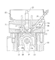
- FIG. 2 is a cross-sectional view showing a combustion chamber of a diesel engine and its peripheral part.
- FIG. 3 is a block diagram showing a configuration of a control system such as an ECU.
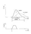
- FIG. 4 is a waveform diagram showing changes in the heat generation rate (heat generation amount per unit rotation angle of the crankshaft) and changes in the fuel injection rate (fuel injection amount per unit rotation angle of the crankshaft) during the combustion stroke. It is.
- FIG. 5 is a diagram illustrating an example of a heat release rate waveform and a fuel injection rate waveform for explaining a misfire sign determination method.
- FIG. 5 is a diagram illustrating an example of a heat release rate waveform and a fuel injection rate waveform for explaining a misfire sign determination method.
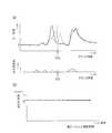
- FIG. 6 shows the experimental results when combustion is performed in the combustion chamber with various fuel injection amounts.
- FIG. 6A shows the heat generation rate waveform and the fuel injection rate waveform for each fuel injection amount.
- FIG. 6B is a diagram showing the relationship between the fuel injection amount and the heat generation efficiency (the amount of heat generated per unit volume of fuel).
- FIG. 7 shows experimental results when combustion is performed in the combustion chamber at various fuel injection pressures.
- FIG. 7A shows a heat generation rate waveform and a fuel injection rate waveform for each fuel injection pressure.
- FIG. 7B is a diagram showing the relationship between the fuel injection pressure and the heat generation efficiency.
- FIG. 8 shows the experimental results when combustion is performed in the combustion chamber at various fuel injection timings.
- FIG. 8A shows the heat release rate waveform and the fuel injection rate waveform at each fuel injection timing.
- FIG. 8B is a diagram showing the relationship between the fuel injection timing and the heat generation efficiency.
- FIG. 9 shows the experimental results when combustion is performed in the combustion chamber at various oxygen excess rates.
- FIG. 9A shows the heat release rate waveform and the fuel injection rate waveform for each oxygen excess rate.
- FIG. 9B is a graph showing the relationship between the oxygen excess rate and the heat generation efficiency.
- FIG. 10 is a diagram illustrating an example of a heat release rate waveform and a fuel injection rate waveform for explaining the misfire sign determination method according to the first modification.
- FIG. 11 is a flowchart showing a procedure of a misfire sign determination operation and a misfire avoidance operation in the first modification.
- FIG. 12 is a diagram illustrating an example of a heat release rate waveform and a fuel injection rate waveform for explaining the misfire sign determination method according to the second modification.
- 13A and 13B are diagrams showing experimental results in various combustion states.
- FIG. 13A shows a heat generation rate waveform and a fuel injection rate waveform
- FIG. 13B shows a change waveform of cumulative heat quantity. It is.
- FIG. 14 is a diagram illustrating experimental results in various combustion states, and is a diagram illustrating a change waveform of heat generation efficiency.
- FIG. 1 is a schematic configuration diagram of an engine 1 and its control system according to the present embodiment.
- FIG. 2 is sectional drawing which shows the combustion chamber 3 of a diesel engine, and its peripheral part.
- the engine 1 is configured as a diesel engine system having a fuel supply system 2, a combustion chamber 3, an intake system 6, an exhaust system 7 and the like as main parts.
- the fuel supply system 2 includes a supply pump 21, a common rail 22, an injector (fuel injection valve) 23, a shutoff valve 24, a fuel addition valve 26, an engine fuel passage 27, an addition fuel passage 28, and the like.
- the supply pump 21 pumps fuel from the fuel tank, makes the pumped fuel high pressure, and supplies it to the common rail 22 via the engine fuel passage 27.
- the common rail 22 has a function as a pressure accumulation chamber that holds (accumulates) the high-pressure fuel supplied from the supply pump 21 at a predetermined pressure, and distributes the accumulated fuel to the injectors 23.
- the injector 23 includes a piezoelectric element (piezo element) therein, and is configured by a piezo injector that is appropriately opened to supply fuel into the combustion chamber 3. Details of the fuel injection control from the injector 23 will be described later.
- the supply pump 21 supplies a part of the fuel pumped up from the fuel tank to the fuel addition valve 26 via the addition fuel passage 28.
- the added fuel passage 28 is provided with the shutoff valve 24 for shutting off the added fuel passage 28 and stopping fuel addition in an emergency.
- the fuel addition valve 26 is configured so that the fuel addition amount to the exhaust system 7 becomes a target addition amount (addition amount at which the exhaust A / F becomes the target A / F) by the addition control operation by the ECU 100.
- the valve opening timing is controlled so that the fuel addition timing becomes a predetermined timing. That is, a desired fuel is injected and supplied from the fuel addition valve 26 to the exhaust system 7 (from the exhaust port 71 to the exhaust manifold 72) at an appropriate timing.
- the intake system 6 includes an intake manifold 63 connected to an intake port 15a formed in the cylinder head 15 (see FIG. 2), and an intake pipe 64 constituting an intake passage is connected to the intake manifold 63. Further, an air cleaner 65, an air flow meter 43, and a throttle valve (intake throttle valve) 62 are arranged in this intake passage in order from the upstream side.
- the air flow meter 43 outputs an electrical signal corresponding to the amount of air flowing into the intake passage via the air cleaner 65.
- the intake system 6 is provided with a swirl control valve (swirl speed variable mechanism) 66 for making the swirl flow (horizontal swirl flow) in the combustion chamber 3 variable (see FIG. 2).
- a swirl control valve swirl speed variable mechanism
- the intake port 15a two systems of a normal port and a swirl port are provided for each cylinder, and a normal valve 15a shown in FIG.
- a swirl control valve 66 is disposed.
- An actuator (not shown) is connected to the swirl control valve 66, and the flow rate of air passing through the normal port 15a can be changed according to the opening of the swirl control valve 66 adjusted by driving the actuator. Yes.
- the larger the opening of the swirl control valve 66 the greater the amount of air taken into the cylinder from the normal port 15a.
- the swirl generated by the swirl port becomes relatively weak, and the inside of the cylinder becomes low swirl (a state where the swirl speed is low).
- the smaller the opening of the swirl control valve 66 the smaller the amount of air drawn into the cylinder from the normal port 15a. For this reason, the swirl generated by the swirl port is relatively strengthened, and the inside of the cylinder becomes a high swirl (a state where the swirl speed is high).
- the exhaust system 7 includes an exhaust manifold 72 connected to the exhaust port 71 formed in the cylinder head 15, and exhaust pipes 73 and 74 constituting an exhaust passage are connected to the exhaust manifold 72. Further, a maniverter (exhaust gas purification device) 77 provided with a NOx storage catalyst (NSR catalyst: NOx Storage Reduction catalyst) 75 and a DPNR catalyst (Diesel Particle-NOx Reduction catalyst) 76 is disposed in the exhaust passage.
- NSR catalyst NOx Storage Reduction catalyst
- DPNR catalyst Diesel Particle-NOx Reduction catalyst
- the NSR catalyst 75 is an NOx storage reduction catalyst.
- alumina Al 2 O 3
- Alkali metal such as barium (Ba), alkaline earth such as calcium (Ca), rare earth such as lanthanum (La) and yttrium (Y), and noble metal such as platinum (Pt) were supported. It has a configuration.
- the NSR catalyst 75 occludes NOx in a state where a large amount of oxygen is present in the exhaust gas, has a low oxygen concentration in the exhaust gas, and a large amount of reducing component (for example, an unburned component (HC) of the fuel).
- reducing component for example, an unburned component (HC) of the fuel.
- NOx is reduced to NO 2 or NO and released.
- NO NOx released as NO 2 or NO the N 2 is further reduced due to quickly reacting with HC or CO in the exhaust.
- HC and CO are oxidized to H 2 O and CO 2 by reducing NO 2 and NO. That is, by appropriately adjusting the oxygen concentration and HC component in the exhaust gas introduced into the NSR catalyst 75, HC, CO, and NOx in the exhaust gas can be purified.
- the oxygen concentration and HC component in the exhaust gas can be adjusted by the fuel addition operation from the fuel addition valve 26.
- the DPNR catalyst 76 is, for example, a NOx occlusion reduction catalyst supported on a porous ceramic structure, and PM in the exhaust gas is collected when passing through the porous wall. Further, when the air-fuel ratio of the exhaust gas is lean, NOx in the exhaust gas is stored in the NOx storage reduction catalyst, and when the air-fuel ratio becomes rich, the stored NOx is reduced and released. Further, the DPNR catalyst 76 carries a catalyst that oxidizes and burns the collected PM (for example, an oxidation catalyst mainly composed of a noble metal such as platinum).
- a cylinder block 11 constituting a part of the engine body is formed with a cylindrical cylinder bore 12 for each cylinder (four cylinders), and a piston 13 is formed inside each cylinder bore 12. Is accommodated so as to be slidable in the vertical direction.
- the combustion chamber 3 is formed above the top surface 13 a of the piston 13. That is, the combustion chamber 3 is defined by the lower surface of the cylinder head 15 attached to the upper part of the cylinder block 11 via the gasket 14, the inner wall surface of the cylinder bore 12, and the top surface 13 a of the piston 13.
- a cavity (concave portion) 13 b is formed in a substantially central portion of the top surface 13 a of the piston 13, and this cavity 13 b also constitutes a part of the combustion chamber 3.
- the concave dimension is small in the central portion (on the cylinder center line P), and the concave dimension is increased toward the outer peripheral side. That is, as shown in FIG. 2, when the piston 13 is in the vicinity of the compression top dead center, the combustion chamber 3 formed by the cavity 13b is a narrow space having a relatively small volume at the center portion, and is directed toward the outer peripheral side. Thus, the space is gradually enlarged (expanded space).
- the piston 13 has a small end portion 18a of a connecting rod 18 connected by a piston pin 13c, and a large end portion of the connecting rod 18 is connected to a crankshaft which is an engine output shaft.
- a glow plug 19 is disposed toward the combustion chamber 3.
- the glow plug 19 functions as a start-up assisting device that is heated red when an electric current is applied immediately before the engine 1 is started and a part of the fuel spray is blown onto the glow plug 19 to promote ignition and combustion.
- the cylinder head 15 is formed with the intake port 15a for introducing air into the combustion chamber 3 and the exhaust port 71 for exhausting exhaust gas from the combustion chamber 3, and intake air for opening and closing the intake port 15a.
- An exhaust valve 17 that opens and closes the valve 16 and the exhaust port 71 is provided.
- the intake valve 16 and the exhaust valve 17 are disposed to face each other with the cylinder center line P interposed therebetween. That is, the engine 1 is configured as a cross flow type.
- the cylinder head 15 is provided with the injector 23 that directly injects fuel into the combustion chamber 3.
- the injector 23 is disposed at a substantially upper center of the combustion chamber 3 in a standing posture along the cylinder center line P, and injects fuel introduced from the common rail 22 toward the combustion chamber 3 at a predetermined timing. It has become.
- the engine 1 is provided with a supercharger (turbocharger) 5.
- the turbocharger 5 includes a turbine wheel 52 and a compressor wheel 53 that are connected via a turbine shaft 51.
- the compressor wheel 53 is disposed facing the intake pipe 64, and the turbine wheel 52 is disposed facing the exhaust pipe 73.
- the turbocharger 5 performs a so-called supercharging operation in which the compressor wheel 53 is rotated using the exhaust flow (exhaust pressure) received by the turbine wheel 52 to increase the intake pressure.
- the turbocharger 5 in the present embodiment is a variable nozzle type turbocharger, and a variable nozzle vane mechanism (not shown) is provided on the turbine wheel 52 side. By adjusting the opening of the variable nozzle vane mechanism, the engine 1 supercharging pressure can be adjusted.
- the intake pipe 64 of the intake system 6 is provided with an intercooler 61 for forcibly cooling the intake air whose temperature has been raised by supercharging in the turbocharger 5.
- the throttle valve 62 provided further downstream than the intercooler 61 is an electronically controlled on-off valve whose opening degree can be adjusted steplessly. It has a function of narrowing down the area and adjusting (reducing) the supply amount of the intake air.
- the engine 1 is provided with an exhaust gas recirculation passage (EGR passage) 8 that connects the intake system 6 and the exhaust system 7.
- the EGR passage 8 is configured to reduce the combustion temperature by recirculating a part of the exhaust gas to the intake system 6 and supplying it again to the combustion chamber 3, thereby reducing the amount of NOx generated.
- the EGR passage 8 is opened and closed steplessly by electronic control, and the exhaust gas passing through the EGR passage 8 (recirculating) is cooled by an EGR valve 81 that can freely adjust the exhaust flow rate flowing through the passage.
- An EGR cooler 82 is provided.
- the EGR passage 8, the EGR valve 81, the EGR cooler 82, and the like constitute an EGR device (exhaust gas recirculation device).
- the air flow meter 43 outputs a detection signal corresponding to the flow rate (intake air amount) of the intake air upstream of the throttle valve 62 in the intake system 6.
- the intake air temperature sensor 49 is disposed in the intake manifold 63 and outputs a detection signal corresponding to the temperature of the intake air.
- the intake pressure sensor 48 is disposed in the intake manifold 63 and outputs a detection signal corresponding to the intake air pressure.
- the A / F (air-fuel ratio) sensor 44 outputs a detection signal that continuously changes in accordance with the oxygen concentration in the exhaust gas downstream of the manipulator 77 of the exhaust system 7.
- the exhaust temperature sensor 45 outputs a detection signal corresponding to the temperature of the exhaust gas (exhaust temperature) downstream of the manipulator 77 of the exhaust system 7.
- the rail pressure sensor 41 outputs a detection signal corresponding to the fuel pressure stored in the common rail 22.
- the throttle opening sensor 42 detects the opening of the throttle valve 62.
- the ECU 100 includes a CPU 101, a ROM 102, a RAM 103, a backup RAM 104, and the like.
- the ROM 102 stores various control programs, maps that are referred to when the various control programs are executed, and the like.
- the CPU 101 executes various arithmetic processes based on various control programs and maps stored in the ROM 102.
- the RAM 103 is a memory that temporarily stores calculation results in the CPU 101, data input from each sensor, and the like.
- the backup RAM 104 is a non-volatile memory that stores data to be saved when the engine 1 is stopped, for example.
- the CPU 101, the ROM 102, the RAM 103, and the backup RAM 104 are connected to each other via the bus 107 and to the input interface 105 and the output interface 106.
- the input interface 105 is connected to the rail pressure sensor 41, the throttle opening sensor 42, the air flow meter 43, the A / F sensor 44, the exhaust temperature sensor 45, the intake pressure sensor 48, and the intake temperature sensor 49. Further, the input interface 105 includes a water temperature sensor 46 that outputs a detection signal corresponding to the cooling water temperature of the engine 1, an accelerator opening sensor 47 that outputs a detection signal corresponding to the depression amount of the accelerator pedal, and an output shaft of the engine 1. Connected are a crank position sensor 40 that outputs a detection signal (pulse) every time the (crankshaft) rotates by a certain angle, an external air pressure sensor 4A that detects the pressure of outside air, an in-cylinder pressure sensor 4B that detects in-cylinder pressure, and the like. Has been.
- the supply interface 21, the injector 23, the fuel addition valve 26, the throttle valve 62, the swirl control valve 66, the EGR valve 81, and the like are connected to the output interface 106.
- an actuator (not shown) provided in the variable nozzle vane mechanism of the turbocharger 5 is also connected to the output interface 106.
- the ECU 100 executes various controls of the engine 1 based on outputs from the various sensors described above, calculated values obtained by arithmetic expressions using the output values, or various maps stored in the ROM 102. .
- the ECU 100 executes pilot injection (sub-injection) and main injection (main injection) as the fuel injection control of the injector 23.
- the pilot injection is an operation for injecting a small amount of fuel in advance prior to the main injection from the injector 23.
- the pilot injection is an injection operation for suppressing the ignition delay of fuel due to the main injection and leading to stable diffusion combustion, and is also referred to as sub-injection.
- the pilot injection in the present embodiment has not only a function of suppressing the initial combustion speed by the main injection described above but also a preheating function of increasing the in-cylinder temperature. That is, after the pilot injection is performed, the fuel injection is temporarily interrupted, and the compressed gas temperature (in-cylinder temperature) is sufficiently increased until the main injection is started to reach the fuel self-ignition temperature (for example, 1000 K). In this way, the ignitability of the fuel injected by the main injection is ensured satisfactorily.
- the main injection is an injection operation (torque generation fuel supply operation) for generating torque of the engine 1.
- the injection amount in the main injection is basically determined so as to obtain the required torque according to the operation state such as the engine speed, the accelerator operation amount, the coolant temperature, the intake air temperature, and the like. For example, the higher the engine speed (the engine speed calculated based on the detection value of the crank position sensor 40), the larger the accelerator operation amount (the accelerator pedal depression amount detected by the accelerator opening sensor 47). As the accelerator opening becomes larger, the required torque value of the engine 1 is higher, and accordingly, the fuel injection amount in the main injection is also set higher.
- the fuel injected by the main injection is immediately exposed to a temperature environment equal to or higher than the auto-ignition temperature, and the thermal decomposition proceeds. Will start burning immediately.
- fuel ignition delay in a diesel engine includes physical ignition delay and chemical ignition delay.
- the physical ignition delay is the time required for evaporation / mixing of the fuel droplets and depends on the gas temperature of the combustion field.
- chemical ignition delay is the time required for chemical bonding and decomposition of fuel vapor and oxidation heat generation.
- the physical ignition delay can be minimized, and as a result, the ignition delay can be minimized. Therefore, as a combustion mode of the fuel injected by the main injection, premixed combustion is hardly performed, and most of it is diffusion combustion.
- controlling the injection timing of the main injection is substantially equivalent to controlling the start timing of diffusion combustion as it is, and the controllability of combustion can be greatly improved. That is, by controlling the ignition timing and heat generation amount by controlling the fuel injection timing and fuel injection amount in the main injection by minimizing the proportion of premixed combustion of the fuel injected in the main injection, Controllability can be greatly improved.
- After injection is an injection operation for increasing the exhaust gas temperature. Specifically, after injection is performed at a timing at which most of the combustion energy of the supplied fuel is obtained as thermal energy of the exhaust gas without being converted into torque of the engine 1.
- the post-injection is an injection operation for directly introducing fuel into the exhaust system 7 to increase the temperature of the manipulator 77. For example, when the accumulated amount of PM trapped in the DPNR catalyst 76 exceeds a predetermined amount (for example, detected by detecting a differential pressure before and after the manipulator 77), post injection is performed. .
- the ECU 100 controls the opening degree of the EGR valve 81 according to the operating state of the engine 1 and adjusts the exhaust gas recirculation amount (EGR amount) toward the intake manifold 63.
- the EGR amount is set according to an EGR map stored in advance in the ROM 102.
- this EGR map is a map for determining the EGR amount (EGR rate) using the engine speed and the engine load as parameters.
- This EGR map is created in advance by experiments, simulations, or the like. That is, by applying the engine speed calculated based on the detection value of the crank position sensor 40 and the opening of the throttle valve 62 (corresponding to the engine load) detected by the throttle opening sensor 42 to the EGR map. An EGR amount (opening degree of the EGR valve 81) is obtained.
- the ECU 100 executes the opening degree control of the swirl control valve 66.
- the opening degree of the swirl control valve 66 the amount of movement of the fuel spray injected into the combustion chamber 3 per unit time (or per unit crank rotation angle) in the circumferential direction in the cylinder is changed. Is called.
- the fuel injection pressure when executing the fuel injection is determined by the internal pressure of the common rail 22.
- the target value of the fuel pressure supplied from the common rail 22 to the injector 23, that is, the target rail pressure increases as the engine load (engine load) increases and the engine speed (engine speed) increases. It will be expensive. That is, when the engine load is high, the amount of air sucked into the combustion chamber 3 is large. Therefore, a large amount of fuel must be injected from the injector 23 into the combustion chamber 3, and therefore the injection from the injector 23 is performed.
- the pressure needs to be high.
- the target rail pressure is generally set based on the engine load and the engine speed.
- the target rail pressure is set according to a fuel pressure setting map stored in the ROM 102, for example. That is, by determining the fuel pressure according to this fuel pressure setting map, the valve opening period (injection rate waveform) of the injector 23 is controlled, and the fuel injection amount during the valve opening period can be defined.
- the fuel pressure is adjusted between 30 MPa and 200 MPa according to the engine load and the like.
- the optimum values vary depending on the temperature conditions of the engine 1 and the intake air.
- the ECU 100 adjusts the fuel discharge amount of the supply pump 21 so that the common rail pressure becomes equal to the target rail pressure set based on the engine operating state, that is, the fuel injection pressure matches the target injection pressure. To measure. Further, the ECU 100 determines the fuel injection amount and the fuel injection form based on the engine operating state. Specifically, the ECU 100 calculates the engine rotation speed based on the detection value of the crank position sensor 40, obtains the amount of depression of the accelerator pedal (accelerator opening) based on the detection value of the accelerator opening sensor 47, The total fuel injection amount (the sum of the injection amount in pilot injection and the injection amount in main injection) is determined based on the engine speed and the accelerator opening.
- the solid line of the waveforms shown in the upper part of FIG. 4 shows an ideal heat generation rate waveform related to the combustion of fuel injected in pilot injection and main injection, with the horizontal axis representing the crank angle and the vertical axis representing the heat generation rate.
- TDC in the figure indicates the crank angle position corresponding to the compression top dead center of the piston 13.
- the waveform shown in the lower part of FIG. 4 shows the waveform of the injection rate of fuel injected from the injector 23 (fuel injection amount per unit rotation angle of the crankshaft).
- the heat release rate waveform for example, combustion of fuel injected by main injection is started from the vicinity of the compression top dead center (TDC) of the piston 13, and a predetermined piston position after the compression top dead center of the piston 13 (for example, The heat generation rate reaches a maximum value (peak value) at 10 degrees after compression top dead center (ATDC 10 °), and a predetermined piston position after compression top dead center (for example, 25 degrees after compression top dead center ( At the time of ATDC 25 °), the combustion of the fuel injected in the main injection ends.
- the combustion center of gravity is 10 degrees after compression top dead center (ATDC 10 °)
- about 50% of the total heat generation amount in the expansion stroke is generated by ATDC 10 °, and the engine 1 is operated with high thermal efficiency. Is possible.
- crank angle and the fuel injection rate waveform when the combustion center of gravity is reached is the period from when the fuel injection stop signal is transmitted to the injector 23 until the fuel injection is completely stopped (see FIG. 4, the combustion center of gravity is located in the period T).
- the cylinder is sufficiently preheated by pilot injection, and the fuel injected in the main injection is immediately self-ignited by this preheating.
- the thermal decomposition proceeds due to exposure to a temperature environment higher than the temperature, and combustion starts immediately after injection.
- the waveform indicated by the two-dot chain line ⁇ in FIG. 4 is a heat generation rate waveform when the fuel injection pressure is set higher than the appropriate value, and both the combustion rate and the peak value of the heat generation rate are too high. Therefore, there is a concern about an increase in combustion noise and an increase in the amount of NOx generated.
- a waveform indicated by a two-dot chain line ⁇ in FIG. 4 is a heat generation rate waveform when the fuel injection pressure is set lower than an appropriate value, and the timing at which the combustion rate is low and the peak of the heat generation rate appears. There is a concern that sufficient engine torque cannot be secured due to the large shift to the retard side.
- misfire precursor determination method determination method for deterioration of combustion state
- the oxygen concentration and oxygen excess rate in the combustion chamber 3 are sufficiently secured (for example, the oxygen concentration is 17% or more, the oxygen excess rate is 1.5 or more), the in-cylinder temperature has reached the self-ignition temperature of the fuel (for example, 1000 K), and the fuel injection amount command value from the ECU 100
- the amount of heat generated per unit volume of fuel during the entire combustion period of the fuel is always constant (the fuel injection amount, the fuel injection timing, etc. are different). Is also constant). In other words, the maximum amount of heat generated per unit volume of fuel over the entire combustion period (if good combustion is performed, most of the fuel will contribute to heat generation.
- the amount of heat generated is always a constant value.
- the amount of heat generated per unit volume of fuel here refers to the amount of fuel injected from the injector 23 (fuel injected according to the fuel injection amount command value) up to the end of the combustion period in the entire period of the combustion period. This is a value obtained by dividing the amount of heat generated by combustion by the amount of fuel corresponding to the fuel injection amount command value. In other words, it is the average value of the amount of heat generated per unit volume of fuel during the combustion period.
- the maximum value of the amount of generated heat per unit volume of the fuel is always a constant value because the combustion period of the fuel injected by the pilot injection, the combustion period of the fuel injected by the main injection, and This applies to all of the combustion periods over these two periods.
- FIG. 5 is a diagram showing an example of a heat generation rate waveform and a fuel injection rate waveform.
- the combustion of the fuel is started with a slight delay (ignition delay) after the start of the injection (timing T1 in FIG. 5), and reaches the combustion center of gravity. During this period, the heat generation rate gradually increases. Then, after reaching the combustion center of gravity, the heat generation rate gradually decreases, and when the combustion of most of the fuel is completed, the heat generation rate becomes “0” (timing T2 in FIG. 5).
- timing T2 in FIG. 5 In this case, if good combustion is performed in the combustion chamber 3, most of the fuel contributes to the generation of heat, so the fuel in the entire combustion period (period T1 to timing T2 in FIG. 5). The amount of heat generated per unit volume is maximum.
- timing T1 and T2 The acquisition of the combustion start timing (timing T1) and the combustion end timing (timing T2) is performed based on the change in the in-cylinder pressure detected by the in-cylinder pressure sensor 4B. Further, the ignition delay period after fuel injection may be calculated from the in-cylinder environment (sensing values of various sensors), thereby obtaining the combustion start timing (timing T1). Furthermore, timings obtained in advance by reference combustion (combustion by an ideal heat generation rate waveform) may be set as the timings T1 and T2.
- the amount of heat generated per unit volume of fuel over the entire combustion period becomes the maximum value.
- the maximum value of the amount of heat generated per unit volume of fuel over the entire combustion period is referred to as “reference heat generation efficiency”.
- the maximum value of heat generated per unit volume of fuel is 30 J / mm 3 .
- This value is an experimentally obtained value.
- the calorific value per unit mass of light oil is 42.94 kJ / g and the density of light oil is 0.834 ⁇ 10 ⁇ 3 g / mm 3
- the maximum value of generated heat per unit volume is theoretically Although the above is 35.8 J / mm 3
- this heat generation amount (the heat generation amount obtained from the reference heat generation efficiency and the fuel injection amount; hereinafter referred to as the reference heat generation amount) is used as a reference, and this reference heat generation amount (or this reference heat generation amount is predetermined) It is also possible to determine a sign of misfire occurrence by comparing the actual heat generation amount with a value obtained by multiplying the ratio of the above-mentioned ratio and the present invention includes such a determination method within the scope of the technical idea. .
- the inventor of the present invention conducted an experiment to confirm that the reference heat generation efficiency was 30 J / mm 3 .
- FIG. 6 shows that ideal combustion (oxygen concentration and excess oxygen ratio in the combustion chamber 3 is sufficiently ensured in the combustion chamber 3 by varying the fuel injection amounts (injection amounts of pilot injection and main injection).
- the experiment results when the in-cylinder temperature reaches the self-ignition temperature of the fuel and combustion is performed when an amount of fuel corresponding to the fuel injection amount command value is injected from the injector 23 are shown.
- FIG. 6A shows a heat generation rate waveform and a fuel injection rate waveform for each fuel injection
- FIG. 6B shows a fuel injection amount (fuel injection amount in pilot injection) and heat generation efficiency (injected by pilot injection). The relationship between the combustion period of the fuel and the combustion period of the fuel injected in the main injection in the whole fuel) is shown.
- FIG. 6A shows a heat generation rate waveform and a fuel injection rate waveform for each fuel injection
- FIG. 6B shows a fuel injection amount (fuel injection amount in pilot injection) and heat generation efficiency (injected by pilot injection). The relationship between the combustion period of the fuel and the combustion period of
- the solid line indicates the case where the pilot injection amount is 16 mm 3 and the main injection amount is 19 mm 3
- the broken line indicates the case where the pilot injection amount is 12 mm 3 and the main injection amount is 23 mm 3
- the alternate long and short dash line indicates the pilot
- the injection amount is 8 mm 3 and the main injection amount is 27 mm 3 are shown.
- the amount of heat generated per unit volume (reference heat generation efficiency) when ideal combustion is performed is about 30 J / It is mm 3 .
- FIG. 7 shows experimental results when ideal combustion is performed in the combustion chamber 3 at various fuel injection pressures (rail pressures).
- FIG. 7A shows a heat generation rate waveform and a fuel injection rate waveform for each fuel injection pressure
- FIG. 7B shows a relationship between the fuel injection pressure and the heat generation efficiency.
- FIG. 7A shows the experimental results when the fuel injection pressure is set higher in the order of the one-dot chain line, the broken line, and the solid line.
- the amount of heat generated per unit volume of fuel (reference heat generation efficiency) when ideal combustion is performed is about 30 J / mm 3 . It has become.
- FIG. 8 shows an experiment in which ideal combustion is performed in the combustion chamber 3 by varying the fuel injection timing (injection timing of the second pilot injection when two pilot injections are executed). Results are shown.
- FIG. 8A shows a heat generation rate waveform and a fuel injection rate waveform for each fuel injection timing
- FIG. 8B shows a relationship between the fuel injection timing and the heat generation efficiency.
- FIG. 8A shows an experimental result when the injection timing of the second pilot injection is advanced in the order of the one-dot chain line, the broken line, and the solid line.
- the amount of heat generated per unit volume of fuel reference heat generation efficiency
- FIG. 9 shows experimental results when ideal combustion is performed in the combustion chamber 3 at various oxygen excess rates.
- FIG. 9A shows a heat generation rate waveform and a fuel injection rate waveform for each oxygen excess rate
- FIG. 9B shows a relationship between the oxygen excess rate and the heat generation efficiency.
- FIG. 9A shows the experimental results when the oxygen excess rate is increased in the order of the one-dot chain line, the broken line, and the solid line.
- the standard heat generation efficiency is about 30 J / mm 3 .
- the maximum value of the amount of heat generated per unit volume of fuel over the entire combustion period is about 30 J / mm 3 .
- the timing for determining the sign of misfire within the entire period of the combustion period (the period from timing T1 to timing T2 in FIG. 5).
- a misfire sign determination time (for example, timing T3 in FIG. 5).
- the misfire sign determination time can be set as an arbitrary time, but it is preferable to set the misfire sign determination time to the retard side of the combustion center of gravity in order to improve the accuracy of the misfire sign determination.
- the time point at which 80% of the total heat generation amount when it is assumed that good combustion is performed in the combustion chamber 3 is set as the misfire sign determination time. ing.
- the misfire sign determination timing is set based on the combustion start timing. For example, it is set to the retard side by a predetermined crank angle from the combustion start timing (only the crank angle at which 80% of the total heat generation amount is obtained; for example, 20 ° CA only). For example, when the combustion is started at the compression top dead center (TDC), the time at which the crank angle is 20 degrees after the compression top dead center (ATDC 20 °) is set as the misfire sign determination timing.
- TDC compression top dead center
- ATDC 20 ° the time at which the crank angle is 20 degrees after the compression top dead center
- misfire precursor heat generation efficiency threshold is defined, and this misfire precursor heat generation efficiency threshold is assigned in advance to the misfire precursor determination timing.
- the heat generation efficiency (predetermined ratio serving as a threshold for the presence or absence of a sign) is set as a threshold for the presence or absence of a sign of the occurrence of misfire.
- the ratio here is, for example, the ratio of the amount of heat generated in the period up to the misfire sign determination time to the amount of heat generated in the entire combustion period when ideal combustion is performed, and the possibility of misfire occurrence It corresponds to a value obtained by multiplying the ratio of the generated heat quantity. That is, in the case of this embodiment, since this ratio is 64%, the misfire precursor heat generation efficiency threshold value is 19.2 J / mm 3 .
- the misfire precursor heat generation efficiency threshold value may be set by experiment, simulation, or the like.
- the amount of heat actually generated by the fuel combustion until the misfire sign determination time is the fuel injection amount commanded by the fuel injection amount command value.
- the actual heat generation efficiency is obtained (actual heat generation efficiency calculation operation by the actual heat generation efficiency calculation means), and when the actual heat generation efficiency has not reached the misfire precursor heat generation efficiency threshold, In FIG. 2, it is determined that there is a sign of misfire occurrence (operation for determining a sign of misfire occurrence by the misfire sign determination means).
- a period from timing T1 to timing T3 in FIG. 5 is set as a misfire sign determination period, and the amount of heat generated in the misfire sign determination period is set as the fuel injection amount commanded by the fuel injection amount command value.
- the actual heat generation efficiency is obtained by dividing, and the actual heat generation efficiency is compared with the misfire precursor heat generation efficiency threshold. For example, when the misfire precursor heat generation efficiency threshold is set to 19.2 J / mm 3 , if the combustion of 64% of the injected fuel is not completed by the misfire precursor judgment timing, misfire will occur in the future. The judgment of misfire signs will be made based on the judgment criteria that there is a possibility of this.
- the actual heat generation efficiency at the misfire sign determination timing is 19.2 J / mm 3 or more, it is determined that there is no sign of misfire, and it is determined that correction of the fuel injection amount is not necessary. If the actual heat generation efficiency at the determination time is less than 19.2 J / mm 3 , a correction operation for avoiding misfire (preventing misfire) is executed because there is a sign of misfire. For example, in the heat generation rate waveform indicated by the broken line in FIG. 5, the actual heat generation efficiency at the misfire sign determination time is 10 J / mm 3. In this case, it is assumed that there is a sign of misfire, so that misfire is avoided. Execute correction operation.
- the misfire sign determination timing is set as a timing after the time when the fuel injection operation is completed.
- the fuel injection mode is corrected to improve the combustion state (avoid misfire) (correction operation of the fuel injection mode by the correcting means) ). This will be specifically described below.
- the above-described combustion improvement operation is performed on the cylinder that reaches the next combustion stroke. Further, the combustion improving operation may be executed in the next combustion stroke in the same cylinder.
- the amount of heat generated in the combustion chamber 3 is increased by increasing the fuel injection amount, thereby avoiding misfire.
- the increase correction amount is set to be larger as the deviation amount is larger in accordance with the deviation amount of the actual heat generation efficiency from the misfire precursor heat generation efficiency threshold at the misfire precursor determination timing.
- an increase correction amount map created by experiment or simulation is stored in the ROM 102 in advance, and the increase correction amount is obtained according to this increase correction amount map.
- fuel is diffused in the combustion chamber 3 by correcting the advance angle of the fuel injection timing, thereby optimizing the equivalence ratio in the combustion field (suppressing the equivalence ratio from becoming overrich) and combustion efficiency. Is increased to increase the heat generation amount, and in order to compensate for a decrease in the combustion speed, the preheating period is extended to avoid misfire.
- the advance angle correction amount according to the deviation amount of the actual heat generation efficiency with respect to the misfire precursor heat generation efficiency threshold at the misfire predictor determination time, the larger the deviation amount, the larger the advance angle correction amount is set. Yes.
- an advance angle correction amount map created by experiment or simulation is stored in the ROM 102 in advance, and the advance angle correction amount is obtained according to the advance angle correction amount map.
- the combustion field in the combustion chamber 3 is divided, thereby optimizing the equivalence ratio in each combustion field, increasing the combustion efficiency and increasing the heat generation amount. Avoid misfires.
- the number of divisions is increased as the divergence amount increases in accordance with the divergence amount of the actual heat generation efficiency with respect to the misfire precursor heat generation efficiency threshold at the misfire precursor determination timing.
- a division number map created by experiment or simulation is stored in the ROM 102 in advance, and the division number is obtained according to this division number map.
- the fuel injection amount increase correction, the fuel injection timing advance correction, and the multi-stage fuel injection frequency may be executed in a case where it is determined that there is a sign of misfiring, A plurality of these may be executed simultaneously.
- the presence / absence of a misfire sign is determined by comparing the misfire sign heat generation efficiency threshold with the actual heat generation efficiency.
- the misfire precursor heat generation efficiency threshold and the actual heat generation efficiency can be obtained quantitatively even if the type of engine and the fuel injection amount are different. For this reason, in this embodiment, it is not necessary to prescribe the judgment criteria for the misfire sign determination separately for each type of engine and each fuel injection amount, and a system common to various engines and various fuel injection amounts. It is possible to establish a criterion for predictive misfire signs. As a result, it is possible to quantify the determination criteria for the misfire sign determination, and it is possible to simplify the determination operation.
- the presence or absence of a sign of misfire is judged by comparing the threshold value of the misfire sign heat generation efficiency and the actual heat generation efficiency (comparing numerical values). It is possible to determine whether or not there is a sign of misfire by a relatively simple calculation, and to easily set the determination criteria.
- misfire precursor heat generation efficiency threshold and the actual heat generation efficiency are obtained as average values of the amount of heat generated per unit volume of fuel in a predetermined period (the misfire precursor determination period), and thus are acquired as values with small errors. As a result, it is possible to obtain high accuracy in determining whether or not there is a sign of misfire.
- the method of the present embodiment it is possible to detect the crank angle position when the heat generation efficiency is 50%. That is, the combustion gravity center position can be detected. For this reason, it is also possible to recognize a shift (phase shift) of the combustion gravity center position in actual combustion with respect to the combustion gravity center position when good combustion is performed.
- the fuel injection amount in the pilot injection it is possible to optimize the fuel injection amount in the pilot injection. That is, it is possible to eliminate the need for the fine injection amount learning (also called the fine Q learning) that has been conventionally performed in order to optimize the fine injection amount.
- This conventional minute injection amount learning is performed with a very small amount equivalent to the pilot injection amount when there is no injection when the command injection amount to the injector becomes zero (for example, when the accelerator opening becomes “0” during traveling).
- Fuel is injected toward a specific cylinder (a cylinder where the piston is near compression top dead center) (hereinafter, this fuel injection is referred to as “single injection”), and the amount of change in engine speed associated with this single injection ( Engine operation state change amount), and the engine operation state change amount data when the single injection of a predetermined amount is accurately executed and the engine operation state change amount when the single injection is actually performed.
- the learning value of the pilot injection amount setting map is corrected in accordance with the deviation amount. In other words, learning execution opportunities are limited and useless fuel injection is required.
- the minute injection amount pilot injection amount
- Modification 1 a heat release rate waveform by combustion of fuel injected by pilot injection (hereinafter also referred to as pilot combustion) and combustion of fuel injected by main injection (hereinafter also referred to as main combustion) may be used.
- pilot combustion pilot injection
- main combustion main injection
- FIG. 10 is a diagram showing a heat release rate waveform and a fuel injection rate waveform for explaining a misfire sign determination method in such a case.
- the misfire sign determination timing is set to each of the combustion period of the pilot combustion and the combustion period of the main combustion. At each misfire sign determination period, the determination of the presence or absence of the misfire sign for the pilot combustion and the misfire for the main combustion are performed. The presence / absence of a sign is determined.
- the misfire predictor determination timing is set at a plurality of times within the combustion period of the injected fuel, and the misfire predictor heat generation efficiency threshold is assigned in advance to each misfire predictor determination timing to determine whether or not there is a misfire predictor. Like to do.
- the misfire sign determination timing during the combustion period of pilot combustion can be set as an arbitrary time, but it is preferable to set the misfire sign determination timing to the retard side from the combustion center of gravity in pilot combustion in order to improve the accuracy of the misfire sign determination.
- the time point at which about 70% of the total heat generation amount when it is assumed that the pilot combustion is performed satisfactorily is set as the misfire sign determination time for the pilot combustion. Yes. That is, when good pilot combustion is performed in the combustion chamber 3, a heat generation efficiency of 21 J / mm 3 or more is obtained at this misfire sign determination timing.
- This misfire sign determination time is set based on the combustion start time of pilot combustion. For example, when good pilot combustion is being performed, only the predetermined crank angle from the start timing of pilot combustion (only the crank angle at which 70% of the total heat generation amount is obtained) is retarded Set to
- the misfire precursor heat generation efficiency threshold is defined by multiplying the reference heat generation efficiency (30 J / mm 3 ) in the entire combustion period of the pilot combustion by a predetermined ratio, and this misfire precursor heat generation efficiency.
- a threshold is assigned in advance to the misfire sign determination time.
- the heat generation efficiency (predetermined ratio serving as a threshold value for occurrence of a sign of occurrence) is set as a threshold value for the presence or absence of a sign of occurrence of misfire.
- the misfire precursor heat generation efficiency threshold value may be set by experiment, simulation, or the like.
- the amount of heat actually generated by the fuel combustion until the misfire sign determination time is divided by the fuel injection amount commanded by the fuel injection amount command value.
- the actual heat generation efficiency is obtained, and when the actual heat generation efficiency does not reach the misfire precursor heat generation efficiency threshold, it is determined that there is a sign of misfire occurrence in the pilot combustion.
- the period from timing T4 to timing T5 in FIG. 10 is set as a misfire sign determination period for pilot combustion, and the amount of heat generated during this misfire sign determination period is set as a fuel injection amount command value for pilot injection.
- the actual heat generation efficiency is obtained by dividing by the fuel injection amount commanded by the above, and the actual heat generation efficiency is compared with the misfire precursor heat generation efficiency threshold. For example, when the misfire precursor heat generation efficiency threshold is set to 12.5 J / mm 3 , if the combustion of about 42% of the injected fuel is not completed by the misfire precursor judgment timing, Based on the judgment criteria that there is a possibility of misfire, the misfire precursor is judged.
- the actual heat generation efficiency at the misfire sign determination timing is 12.5 J / mm 3 or more, it is determined that there is no sign of misfire, and it is determined that correction of the fuel injection amount is not necessary.
- the actual heat generation efficiency at the determination time is less than 12.5 J / mm 3 , a correction operation for avoiding misfire is executed because there is a sign of misfire.
- the misfire sign determination timing during the combustion period of the main combustion can be set as an arbitrary time, it is preferable to set the misfire sign determination timing to the retard side from the combustion center of gravity in the main combustion in order to improve the accuracy of the misfire sign determination.
- the total heat generation amount in this case, the sum of the heat generation amount in the pilot combustion and the heat generation amount in the main combustion
- the time point at which about 90% of the heat generation amount is obtained is set as the misfire sign determination time for the main combustion.
- This misfire sign determination time is set based on the combustion start time of pilot combustion. For example, when good pilot combustion and main combustion are performed, only a predetermined crank angle from the start timing of pilot combustion (only a crank angle at which 90% of the total heat generation amount is obtained; For example, only 30 ° CA) is set on the retard side. For example, when the pilot combustion is started at 10 ° before the compression top dead center (BTDC 10 °), the time point 20 degrees after the compression top dead center (ATDC 20 °) is set as the misfire sign determination timing for the main combustion. become.
- the misfire sign heat generation efficiency threshold is defined by multiplying the reference heat generation efficiency (30 J / mm 3 ) in the entire combustion period of the pilot combustion and the main combustion by a predetermined ratio, and this misfire sign.
- a heat generation efficiency threshold is assigned in advance to the misfire sign determination time.
- the heat generation efficiency (predetermined ratio serving as a threshold for the presence or absence of a sign) is set as a threshold for the presence or absence of a sign of the occurrence of misfire.
- the misfire precursor heat generation efficiency threshold value may be set by experiment, simulation, or the like.
- the amount of heat actually generated by the fuel combustion until the misfire sign determination time is divided by the fuel injection amount commanded by the fuel injection amount command value.
- the actual heat generation efficiency is obtained, and when the actual heat generation efficiency does not reach the misfire precursor heat generation efficiency threshold, it is determined that there is a sign of misfire occurrence in the main combustion.
- a period from timing T4 to timing T6 in FIG. 10 is set as a misfire sign determination period for main combustion, and the amount of heat generated in the misfire sign determination period is determined as fuel for each of the pilot injection and the main injection.
- the actual heat generation efficiency is obtained by dividing by the sum of the fuel injection amounts commanded by the injection amount command value, and the actual heat generation efficiency is compared with the misfire precursor heat generation efficiency threshold. For example, when the misfire precursor heat generation efficiency threshold is set to 24 J / mm 3 , if the combustion of about 80% of the injected fuel is not completed by the misfire precursor judgment timing, a misfire may occur in the future. Judgment of misfire signs will be made based on the judgment criteria that there is a possibility.
- the misfire sign determination time is 24 J / mm 3 or more, it is determined that there is no sign of misfire and it is determined that correction of the fuel injection amount is not necessary, whereas the misfire sign determination time
- the actual heat generation efficiency at is less than 24 J / mm 3 , a correction operation for avoiding misfire is executed because there is a sign of misfire.
- FIG. 11 is a flowchart showing a specific procedure of the misfire sign determination operation / misfire avoidance operation in this example.
- the flowchart shown in FIG. 11 is executed every time the combustion stroke in the combustion chamber 3 is started after the engine 1 is started.
- the misfire sign determination timing of pilot combustion is TDC
- the misfire sign determination timing of main combustion is ATDC 20 °
- the misfire sign heat generation efficiency threshold value in pilot combustion is 12.5 J / mm 3.
- the misfire precursor heat generation efficiency threshold in the main combustion is 24 J / mm 3 .
- step ST1 it is determined whether or not the crank angle position of the crankshaft has reached TDC (compression top dead center of the piston 13). If the crank angle position has not yet reached TDC and NO is determined in step ST1, the process returns as it is.
- step ST1 When the crank angle position reaches TDC and YES is determined in step ST1, the process proceeds to step ST2, and the actual heat generation efficiency is calculated when the crank angle position reaches TDC. That is, the actual heat generation efficiency is calculated by dividing the amount of heat generated by the fuel injected by pilot injection until the crank angle position reaches TDC by the amount of fuel corresponding to the fuel injection amount command value in pilot injection. To do.
- step ST3 it is determined whether or not the calculated actual heat generation efficiency has reached 12.5 J / mm 3 .
- the combustion of the fuel injected by the pilot injection is good, that is, in the cylinder by the pilot combustion. Preheating is performed well, and it is determined that there is no sign of misfire in the combustion of the fuel injected by the pilot injection, and the process proceeds to step ST4.
- step ST7 a misfire avoidance operation for improving the combustion of the fuel injected by the pilot injection is executed.
- the misfire avoidance operation include the above-described fuel injection amount increase correction, fuel injection timing advance correction, and multi-stage fuel injection frequency.
- the above-described combustion improvement operation is performed on the cylinder that reaches the next combustion stroke. Further, the combustion improving operation may be executed in the next combustion stroke in the same cylinder.
- step ST4 it is determined whether or not the crank angle position of the crankshaft has reached 20 degrees (ATDC 20 °) after compression top dead center. If the crank angle position has not yet reached ATDC 20 ° and the determination in step ST4 is NO, it waits for the crank angle position to reach ATDC 20 °. If the crank angle position reaches ATDC 20 ° and a YES determination is made in step ST4, the process proceeds to step ST5, where the actual heat generation efficiency is calculated when the crank angle position reaches ATDC 20 °. That is, the amount of heat generated by the fuel injected by the pilot injection and the fuel injected by the main injection until the crank angle position reaches ATDC 20 ° is expressed as the fuel amount corresponding to the fuel injection amount command value in pilot injection. The actual heat generation efficiency is calculated by dividing by the sum of the fuel amount corresponding to the fuel injection amount command value in the main injection.
- step ST6 it is determined whether or not the calculated actual heat generation efficiency has reached 24 J / mm 3 .
- the combustion of the fuel injected in the main injection is good, that is, an appropriate torque is generated by the main combustion. Therefore, the combustion of the fuel injected in the main injection is returned with no sign of misfire.
- step ST6 a misfire avoidance operation for improving the combustion of the fuel injected in the main injection is executed.
- the misfire avoidance operation include the above-described fuel injection amount increase correction, fuel injection timing advance correction, and multi-stage fuel injection frequency.
- the combustion improving operation is performed on the cylinder that reaches the next combustion stroke with respect to the combustion stroke determined to have a sign of misfire. Further, the combustion improving operation may be executed in the next combustion stroke in the same cylinder.
- the actual heat generation efficiency when the actual heat generation efficiency is not improved (the actual heat generation efficiency approaches the misfire predictive heat generation efficiency threshold) in spite of performing the misfire avoidance operation, the actual heat generation efficiency is not improved. It is determined that the cause of the heat generation efficiency being lower than the misfire precursor heat generation efficiency threshold is an abnormality in the intake system 6, and a correction operation for increasing the amount of oxygen introduced into the combustion chamber 3 may be performed. Good.
- the supercharging amount is increased by reducing the EGR gas amount by reducing the opening degree of the EGR valve 81 or by controlling the variable nozzle vane mechanism of the supercharger 5 (decreasing the opening degree of the nozzle vane).
- FIG. 12 is a diagram showing a heat release rate waveform and a fuel injection rate waveform for explaining a misfire sign determination method in such a case.
- the misfire sign determination time is set to each of the combustion period of the pilot combustion and the combustion period of the main combustion, and at each misfire sign determination time, the determination of the presence or absence of the misfire sign for the pilot combustion and the main combustion Judgment is made on whether or not there is a misfire sign.
- the determination of the presence or absence of a misfire sign for pilot combustion in this example is performed in the same manner as in the first modification described above. That is, the period from timing T4 to timing T5 in FIG. 12 is set as a pilot combustion misfire sign determination period, and the amount of heat generated in this misfire sign determination period is commanded by the fuel injection amount command value for pilot injection.
- the actual heat generation efficiency is obtained by dividing by the fuel injection amount, and the actual heat generation efficiency is compared with the misfire precursor heat generation efficiency threshold. For example, when the misfire precursor heat generation efficiency threshold is set to 12.5 J / mm 3 , if the combustion of 42% of the injected fuel is not completed by the misfire precursor judgment timing, misfire will occur in the future.
- misfire signs will be made based on the judgment criteria that there is a possibility of this.
- the actual heat generation efficiency at the misfire sign determination timing is 12.5 J / mm 3 or more, it is determined that there is no sign of misfire, and it is determined that correction of the fuel injection amount is not necessary.
- the actual heat generation efficiency at the determination time is less than 12.5 J / mm 3 , a correction operation for avoiding misfire is executed because there is a sign of misfire.
- the misfire sign determination period for main combustion in this example is set as a period from the combustion start timing of main combustion (timing T7 in FIG. 12) to the misfire sign determination timing (timing T8 in FIG. 12).
- the misfire sign determination time can be set as an arbitrary time, but it is preferable to set the misfire sign determination time to the retard side of the combustion center of gravity in the main combustion in order to improve the accuracy of the misfire sign determination. In the case of this example, about 90% of the total heat generation amount (in this case, the heat generation amount only from the main combustion) when it is assumed that the main combustion is performed satisfactorily is obtained.
- the time is set as the misfire sign determination time for the main combustion. That is, when good main combustion is performed in the combustion chamber 3, heat generation efficiency of 27 J / mm 3 or more is obtained at this misfire sign determination timing.
- This misfire sign determination time is set based on the combustion start time of pilot combustion. For example, when good main combustion is performed, the retard side is the predetermined crank angle from the start timing of main combustion (only the crank angle at which 90% of the total heat generation amount is obtained).
- the misfire precursor heat generation efficiency threshold is defined by multiplying the reference heat generation efficiency (30 J / mm 3 ) in the entire combustion period of the main combustion by a predetermined ratio, and this misfire precursor heat generation efficiency.
- a threshold is assigned in advance to the misfire sign determination time.
- the heat generation efficiency (predetermined ratio serving as a threshold for the presence or absence of a sign) is set as a threshold for the presence or absence of a sign of the occurrence of misfire.
- the misfire precursor heat generation efficiency threshold value may be set by experiment, simulation, or the like.
- the amount of heat actually generated by the fuel combustion until the misfire sign determination time (the amount of heat in the main combustion) is the fuel injection amount with respect to the main injection.
- the actual heat generation efficiency is obtained by dividing by the fuel injection amount commanded by the command value, and when this actual heat generation efficiency has not reached the misfire predictive heat generation efficiency threshold, a sign of misfire occurrence is detected in the main combustion. It is determined that there is.
- a period from timing T7 to timing T8 in FIG. 12 is set as a misfire sign determination period for main combustion, and the amount of heat generated in the misfire sign determination period is set as a fuel injection amount command value for main injection.
- the actual heat generation efficiency is obtained by dividing by the fuel injection amount commanded by the above, and the actual heat generation efficiency is compared with the misfire precursor heat generation efficiency threshold. For example, if the misfire precursor heat generation efficiency threshold is set to 24 J / mm 3 , misfire may occur in the future unless 80% of the injected fuel has been combusted by the misfire precursor judgment timing. Judgment of misfire signs will be made based on the judgment criteria that there is a possibility.
- the misfire sign determination time is 24 J / mm 3 or more, it is determined that there is no sign of misfire and it is determined that correction of the fuel injection amount is not necessary, whereas the misfire sign determination time
- the actual heat generation efficiency at is less than 24 J / mm 3 , a correction operation for avoiding misfire is executed because there is a sign of misfire.
- FIG. 13 and 14 are diagrams showing experimental results in various combustion states (various combustion states in which the in-cylinder temperature and gas state are different from each other), and FIG. FIG. 13B shows a change waveform of the cumulative heat quantity, and FIG. 14 shows a change waveform of the heat generation efficiency.
- the actual heat generation efficiency reaches 24 J / mm 3 when the crank angle position is 20 degrees after compression top dead center (ATDC 20 °).
- the actual heat generation efficiency does not reach 12.5 J / mm 3 at the time of TDC.
- there is a sign of misfire in the pilot combustion and then the pilot combustion is misfired.
- the amount of preheating is insufficient, leading to misfire in the main combustion.
- the in-cylinder preheating by pilot combustion is insufficient, so that an ignition delay occurs in the main combustion. (See FIG. 13A).
- the misfire precursor heat generation efficiency threshold in the misfire precursor determination period is used as a threshold for misfire precursor determination.
- the actual heat generation efficiency in the misfire sign determination period is the actual value for the misfire sign determination.
- the “reference heat generation amount” obtained by multiplying the misfire sign heat generation efficiency threshold by the fuel injection amount commanded by the fuel injection amount command value is used for the misfire sign determination. It is specified as a threshold value for this, and the presence or absence of a misfire sign is determined by comparing this "reference heat generation amount” with the heat amount actually generated in the misfire sign determination period (actual heat generation amount). .
- the “reference heat generation amount” is calculated based on the heat generation efficiency (misfire precursor heat generation efficiency threshold), a quantitative value corresponding to the fuel injection amount regardless of the type of engine. Is calculated as follows. For this reason, it is not necessary to prescribe the judgment criteria for the misfire indication separately for each type of engine and each fuel injection amount, and the systematic misfire indication common to various engines and various fuel injection amounts is not required. It is possible to establish a criterion.
- the heat generation efficiency in the entire combustion period is less than 30 J / mm 3 , it can be determined that the amount of fuel corresponding to the fuel injection amount command value has not been injected or that misfire has already occurred. For this reason, it is determined whether or not the heat generation efficiency in the entire combustion period is the maximum value (30 J / mm 3 ), and the heat generation efficiency is 30 J / mm 3 with respect to the embodiment and the modification described above. If it is less, the fuel injection amount is increased or corrected, or the misfire sign determination operation described above is prohibited.
- the start timing of the misfire sign determination period is defined as the start time of the combustion period.
- the present invention is not limited to this, and the start timing of fuel injection may be defined as the start timing of the misfire sign determination period.
- the timing T0 in FIG. 5 is defined as the start timing of the misfire sign determination period.
- the end timing of the misfire sign determination period may be defined based on the combustion center of gravity. For example, there is a case where a position of 10 ° on the retard side with respect to the crank opening is defined as the end timing of the misfire sign determination period.
- the misfire sign determination timing is set at the time of compression top dead center (TDC) and 20 degrees after compression top dead center (ATDC 20 °).
- TDC compression top dead center
- ADC 20 ° 20 degrees after compression top dead center
- the start timing of pilot combustion is 10 ° before compression top dead center (BTDC 10 °)
- TDC compression top dead center
- the misfire sign determination timing is appropriately set according to the start timing of each fuel injection. For example, when the fuel injection timing is retarded to improve exhaust emission, the misfire precursor determination timing is also set to the retarded side accordingly.
- the misfire sign determination timing is , 5 ° after compression top dead center (ATDC 5 °) and 30 ° after compression top dead center (ATDC 30 °).
- the misfire sign determination time is set at two locations.
- the present invention is not limited to this, and the misfire sign determination timing may be set at three or more locations.
- NSR catalyst 75 and the DPNR catalyst 76 are provided as the manipulator 77 in the embodiment and the modification described above, the NSR catalyst 75 and a DPF (Diesel Particle Filter) may be provided.
- DPF Diesel Particle Filter
- the presence / absence of a misfire occurrence is determined based on the amount of heat generated per unit volume of the fuel.
- the occurrence of misfire is determined based on the amount of heat generated per unit mass of the fuel. It is also possible to determine the presence or absence of a sign.
- the amount of heat generated per unit volume of fuel (claims) is “the amount of heat generated per unit mass of fuel” It is synonymous with.
- the present invention is applicable to combustion control for preventing misfire in a combustion chamber in a common rail in-cylinder direct injection multi-cylinder diesel engine mounted on an automobile.
Landscapes
- Engineering & Computer Science (AREA)
- Chemical & Material Sciences (AREA)
- Combustion & Propulsion (AREA)
- Mechanical Engineering (AREA)
- General Engineering & Computer Science (AREA)
- Electrical Control Of Air Or Fuel Supplied To Internal-Combustion Engine (AREA)
- Combined Controls Of Internal Combustion Engines (AREA)
Abstract
燃料の燃焼期間中に設定された失火予兆判定時期毎に割り当てられた燃料の単位体積当たりの発生熱量である失火予兆熱発生効率閾値と、各失火予兆判定時期における実際の燃料の単位体積当たりの発生熱量である実熱発生効率とを比較し、この実熱発生効率が失火予兆熱発生効率閾値に達していない場合には、燃焼室内において失火発生の予兆があると判定して、燃料噴射量の増量補正、燃料噴射タイミングの進角補正、燃料噴射回数の多段化のうち少なくとも一つを実行する。
Description
本発明は、ディーゼルエンジンに代表される圧縮自着火式の内燃機関の制御装置に係る。特に、本発明は、燃焼室内での失火発生の予兆を認識するための対策、及び、失火の発生を回避(予防)するための対策に関する。
従来、自動車用エンジン等として使用されるディーゼルエンジン(以下、単にエンジンと呼ぶ場合もある)において、燃焼室内での燃焼の安定性等を判断するために、燃焼状態の評価を行うことが提案されている(下記の特許文献1及び特許文献2)。
この燃焼状態の評価手法として具体的には、燃焼室内での熱発生率(クランク軸の単位回転角度当たりの熱発生量)の変化である熱発生率波形や、燃焼重心位置(例えば熱発生率が最大となるクランク角度位置)を求め、熱発生率波形が理想的な波形となっているか否か、また、燃焼重心位置が適正な範囲内にあるか否かを判断することで燃焼室内での燃焼状態を評価するようにしていた。
例えば、特許文献1には、筒内圧センサの出力信号に基づいて燃焼室内での燃焼に伴う熱発生率を計算し、この熱発生率の変化を示す熱発生率波形を利用して熱発生率のピーク値を求めることで、燃焼状態の評価を行うことが開示されている。また、特許文献2には、燃焼室内の圧力に基づいて逐次求められる熱発生率から、燃料の着火時期、熱発生率のピーク値、熱発生率積分値(発生した熱量を累積した絶対量)を求めることで、燃焼状態の評価を行うことが開示されている。
このような燃焼状態の評価手法を利用すれば、例えば燃焼室内での失火発生の予兆を認識することが可能となる。
このように、従来では、熱発生率波形等を用い、燃焼室内での燃焼状態を逐次モニタしながら、つまり、燃焼室内での熱発生量(燃焼室内で発生している熱の絶対量)をモニタしながら燃焼状態を評価していた。このため、熱発生率波形を作成して失火の予兆の有無を判断するためには、この熱発生率波形がどのように変化すれば失火の予兆が有ると判定できるのかといった判定基準を予め規定しておく必要がある。ところが、波形認識によって失火予兆の有無を判定する場合に、その判定基準を設定することは難しく、様々な失火発生パターン(燃料噴射量のずれによる失火発生パターン、酸素濃度の低下による失火発生パターン、酸素過剰率の低下による失火発生パターン、筒内温度の低下による失火発生パターンといった様々な失火発生パターン)を解析しながら、そのパターン毎に判定基準を設定していく必要があるため、この判定基準の作成に多大な労力が必要であった。
また、エンジンの種類毎及び燃料噴射量毎に個別に失火予兆判定のための判定基準を規定しておく必要がある。言い換えると、熱発生率波形がどのように変化すれば失火の予兆が有ると判定できるのかといった判定基準をエンジンの種類毎及び燃料噴射量毎に規定しておく必要がある。このように、これまで、種々のエンジン及び各燃料噴射量に共通した体系的な失火予兆判定のための判定基準については未だ確立されておらず、この体系的な失火予兆判定のための判定基準(失火予兆判定を行うために定量化された指標)の提案が求められていた。つまり、失火予兆判定のための基準値の定量化が求められていた。
本発明は、かかる点に鑑みてなされたものであり、その目的とするところは、圧縮自着火式の内燃機関における失火予兆判定が容易に行えると共に、その判定に基づいて失火の予兆が有ると判定された場合には失火の発生を回避することが可能な内燃機関の制御装置を提供することにある。
-課題の解決原理-
上記の目的を達成するために講じられた本発明の解決原理は、所定の失火予兆判定時期までの期間を対象として、失火予兆の判断基準となる燃料の単位体積当たりの発生熱量の閾値(失火予兆判定のための閾値;失火予兆熱発生効率閾値)を規定すると共に、その失火予兆判定時期までにおける実際の燃料の単位体積当たりの発生熱量(実熱発生効率)を求め、これらを比較して、実熱発生効率が失火予兆熱発生効率閾値に達していない場合には、燃焼状態が悪化しており失火の予兆があると判断するようにしている。そして、失火の予兆があると判断された場合には、燃料噴射量の増量補正等の補正動作を実行するようにしている。
上記の目的を達成するために講じられた本発明の解決原理は、所定の失火予兆判定時期までの期間を対象として、失火予兆の判断基準となる燃料の単位体積当たりの発生熱量の閾値(失火予兆判定のための閾値;失火予兆熱発生効率閾値)を規定すると共に、その失火予兆判定時期までにおける実際の燃料の単位体積当たりの発生熱量(実熱発生効率)を求め、これらを比較して、実熱発生効率が失火予兆熱発生効率閾値に達していない場合には、燃焼状態が悪化しており失火の予兆があると判断するようにしている。そして、失火の予兆があると判断された場合には、燃料噴射量の増量補正等の補正動作を実行するようにしている。
-解決手段-
具体的に、本発明は、燃料噴射量指令値に従って燃料噴射弁から燃焼室内に向けて噴射された燃料の自着火による燃焼を行う圧縮自着火式の内燃機関の制御装置を前提とする。この内燃機関の制御装置に対し、上記噴射された燃料の燃焼期間内に失火予兆判定時期を予め設定する。また、上記噴射された燃料の燃焼期間の全期間における燃料の単位体積当たりの発生熱量の最大値である基準熱発生効率に対して、失火発生の予兆の有無の閾値となる所定の比率を乗算することで規定される失火予兆熱発生効率閾値を、上記失火予兆判定時期に予め割り当てておく。そして、上記噴射された燃料の燃焼によって上記失火予兆判定時期までに実際に発生した熱量を、上記燃料噴射量指令値により指令された燃料噴射量で除算することにより実熱発生効率を算出する実熱発生効率算出手段と、上記実熱発生効率が上記失火予兆熱発生効率閾値に達していない場合に、燃焼室内において失火発生の予兆があると判定する失火予兆判定手段とを設ける。
具体的に、本発明は、燃料噴射量指令値に従って燃料噴射弁から燃焼室内に向けて噴射された燃料の自着火による燃焼を行う圧縮自着火式の内燃機関の制御装置を前提とする。この内燃機関の制御装置に対し、上記噴射された燃料の燃焼期間内に失火予兆判定時期を予め設定する。また、上記噴射された燃料の燃焼期間の全期間における燃料の単位体積当たりの発生熱量の最大値である基準熱発生効率に対して、失火発生の予兆の有無の閾値となる所定の比率を乗算することで規定される失火予兆熱発生効率閾値を、上記失火予兆判定時期に予め割り当てておく。そして、上記噴射された燃料の燃焼によって上記失火予兆判定時期までに実際に発生した熱量を、上記燃料噴射量指令値により指令された燃料噴射量で除算することにより実熱発生効率を算出する実熱発生効率算出手段と、上記実熱発生効率が上記失火予兆熱発生効率閾値に達していない場合に、燃焼室内において失火発生の予兆があると判定する失火予兆判定手段とを設ける。
燃焼室内において理想的な燃焼が行われている場合、上記失火予兆判定時期における燃料の単位体積当たりの発生熱量(実熱発生効率)は上記失火予兆熱発生効率閾値に達している。これに対し、燃焼室内における燃焼状態が悪化している場合、上記実熱発生効率は上記失火予兆熱発生効率閾値に達しておらず、この場合、燃焼室内において失火発生の予兆があると判定される。このような判定手法によれば、内燃機関の種類毎及び燃料噴射量毎に個別に失火発生の予兆の有無の判定基準を規定しておく必要がなくなり、種々の内燃機関及び各燃料噴射量に共通した体系的な失火発生の予兆の有無の判定基準を確立することが可能となる。このため、失火発生の予兆の有無の判定基準の定量化を図ることができて、判定動作の簡素化を図ることができる。
また、失火予兆熱発生効率閾値と実熱発生効率との比較(数値同士の比較)により失火発生の予兆の有無を判定することができるため、熱発生率波形の解析によって失火の予兆の有無を判定するものに対し、比較的簡単な演算により失火の予兆の有無の判定が可能になり、また、その判定基準の設定も容易である。
失火の予兆の有無の判定動作として具体的には以下のものが挙げられる。つまり、上記失火予兆判定時期としては以下のように設定される。つまり、失火予兆判定時期を、上記噴射された燃料の燃焼期間内における複数の時期に設定し、各失火予兆判定時期それぞれに対して上記失火予兆熱発生効率閾値を予め割り当てておく。そして、上記各失火予兆判定時期において算出された上記実熱発生効率のうち一つでも、その失火予兆判定時期に割り当てられている失火予兆熱発生効率閾値に達していないものがある場合、上記失火予兆判定手段が、燃焼室内において失火発生の予兆があると判定する構成としている。
このような失火の予兆の有無の判定動作によれば、例えば燃焼室内を予熱するための燃焼やトルク発生のための燃焼それぞれに対して失火の予兆の有無を個別に判定することが可能となる。例えば、燃焼室内の予熱が不十分であってトルク発生のための燃焼に失火が発生する可能性がある状況や、燃焼室内の予熱は十分であるもののトルク発生のための燃焼に失火が発生する可能性がある状況などを判別することが可能になる。
また、燃料噴射形態として副噴射と主噴射とが実行される場合における失火の予兆の有無の判定動作としては以下のものが挙げられる。先ず、上記燃料噴射弁から燃焼室内に向けての燃料噴射として、少なくとも、主噴射と、この主噴射に先立って行われる副噴射とが実行される場合に、副噴射によって噴射された燃料の燃焼が終了するまでに主噴射によって噴射された燃料の燃焼が開始される状況において、上記失火予兆判定時期を、副噴射によって噴射された燃料の燃焼開始時点から主噴射によって噴射された燃料の燃焼開始時点までの期間内、及び、主噴射によって噴射された燃料の燃焼開始時点からその燃焼の終了時点までの期間内においてそれぞれ設定するものである。
また、上記燃料噴射弁から燃焼室内に向けての燃料噴射として、少なくとも、主噴射と、この主噴射に先立って行われる副噴射とが実行される場合に、副噴射によって噴射された燃料の燃焼が終了した後に主噴射によって噴射された燃料の燃焼が開始される状況において、上記失火予兆判定時期を、副噴射によって噴射された燃料の燃焼開始時点からその燃焼の終了時点までの期間内、及び、主噴射によって噴射された燃料の燃焼開始時点からその燃焼の終了時点までの期間内においてそれぞれ設定するものである。
このように複数回の噴射が行われる際に、副噴射によって噴射された燃料の燃焼が終了した後に主噴射によって噴射された燃料の燃焼が開始される場合には、それぞれの燃焼状態を個別に評価することが可能になる。つまり、副噴射で噴射された燃料の燃焼における失火の予兆の有無の判定動作と、主噴射で噴射された燃料の燃焼における失火の予兆の有無の判定動作とを同一の燃焼行程中に行うことが可能になる。
また、失火の予兆が有ると判定された場合の動作として、上記実熱発生効率が上記失火予兆熱発生効率閾値に達しておらず、上記失火予兆判定手段が、燃焼室内において失火発生の予兆があると判定した場合に、燃料噴射形態の補正を行う補正手段を設けている。
そして、この補正手段は、燃料噴射量の増量補正、燃料噴射タイミングの進角補正、燃料噴射回数の多段化のうち少なくとも一つを実行するよう構成している。
本発明では、失火予兆の判断基準となる失火予兆熱発生効率閾値と実際の燃料の単位体積当たりの発生熱量である実熱発生効率とを比較し、実熱発生効率が失火予兆熱発生効率閾値に達していない場合には、燃焼状態が悪化しており失火の予兆があると判断するようにしている。このため、内燃機関の種類毎及び燃料噴射量毎に個別に失火予兆の判定基準を規定しておく必要がなくなり、種々の内燃機関及び各燃料噴射量に共通した体系的な失火予兆の判定基準を確立することが可能となる。また、熱発生率波形の解析によって失火予兆の有無を判定するものに対し、比較的簡単な演算により失火予兆の有無を判定することが可能になる。
以下、本発明の実施の形態を図面に基づいて説明する。本実施形態は、自動車に搭載されたコモンレール式筒内直噴型多気筒(例えば直列4気筒)ディーゼルエンジン(圧縮自着火式内燃機関)に本発明を適用した場合について説明する。
-エンジンの構成-
先ず、本実施形態に係るディーゼルエンジン(以下、単にエンジンという)の概略構成について説明する。図1は本実施形態に係るエンジン1及びその制御系統の概略構成図である。また、図2は、ディーゼルエンジンの燃焼室3及びその周辺部を示す断面図である。
先ず、本実施形態に係るディーゼルエンジン(以下、単にエンジンという)の概略構成について説明する。図1は本実施形態に係るエンジン1及びその制御系統の概略構成図である。また、図2は、ディーゼルエンジンの燃焼室3及びその周辺部を示す断面図である。
図1に示すように、本実施形態に係るエンジン1は、燃料供給系2、燃焼室3、吸気系6、排気系7等を主要部とするディーゼルエンジンシステムとして構成されている。
燃料供給系2は、サプライポンプ21、コモンレール22、インジェクタ(燃料噴射弁)23、遮断弁24、燃料添加弁26、機関燃料通路27、添加燃料通路28等を備えて構成されている。
上記サプライポンプ21は、燃料タンクから燃料を汲み上げ、この汲み上げた燃料を高圧にした後、機関燃料通路27を介してコモンレール22に供給する。コモンレール22は、サプライポンプ21から供給された高圧燃料を所定圧力に保持(蓄圧)する蓄圧室としての機能を有し、この蓄圧した燃料を各インジェクタ23に分配する。インジェクタ23は、その内部に圧電素子(ピエゾ素子)を備え、適宜開弁して燃焼室3内に燃料を噴射供給するピエゾインジェクタにより構成されている。このインジェクタ23からの燃料噴射制御の詳細については後述する。
また、上記サプライポンプ21は、燃料タンクから汲み上げた燃料の一部を、添加燃料通路28を介して燃料添加弁26に供給する。添加燃料通路28には、緊急時において添加燃料通路28を遮断して燃料添加を停止するための上記遮断弁24が備えられている。
また、上記燃料添加弁26は、ECU100による添加制御動作によって排気系7への燃料添加量が目標添加量(排気A/Fが目標A/Fとなるような添加量)となるように、また、燃料添加タイミングが所定タイミングとなるように開弁時期が制御される電子制御式の開閉弁により構成されている。つまり、この燃料添加弁26から所望の燃料が適宜のタイミングで排気系7(排気ポート71から排気マニホールド72)に噴射供給される構成となっている。
吸気系6は、シリンダヘッド15(図2参照)に形成された吸気ポート15aに接続される吸気マニホールド63を備え、この吸気マニホールド63に、吸気通路を構成する吸気管64が接続されている。また、この吸気通路には、上流側から順にエアクリーナ65、エアフローメータ43、スロットルバルブ(吸気絞り弁)62が配設されている。上記エアフローメータ43は、エアクリーナ65を介して吸気通路に流入される空気量に応じた電気信号を出力するようになっている。
また、この吸気系6には、燃焼室3内でのスワール流(水平方向の旋回流)を可変とするためのスワールコントロールバルブ(スワール速度可変機構)66が備えられている(図2参照)。具体的に、上記吸気ポート15aとしては、ノーマルポート及びスワールポートの2系統が各気筒毎に備えられており、そのうち図2に示されているノーマルポート15aに、開度調整可能なバタフライバルブで成るスワールコントロールバルブ66が配置されている。このスワールコントロールバルブ66には図示しないアクチュエータが連繋されており、このアクチュエータの駆動によって調整されるスワールコントロールバルブ66の開度に応じてノーマルポート15aを通過する空気の流量が変更できるようになっている。そして、スワールコントロールバルブ66の開度が大きいほど、ノーマルポート15aから気筒内に吸入される空気量が増加する。このため、スワールポート(図2では図示省略)により発生したスワールは相対的に弱まり、気筒内は低スワール(スワール速度が低い状態)となる。逆に、スワールコントロールバルブ66の開度が小さいほど、ノーマルポート15aから気筒内に吸入される空気量が減少する。このため、スワールポートにより発生したスワールは相対的に強められ、気筒内は高スワール(スワール速度が高い状態)となる。
排気系7は、シリンダヘッド15に形成された上記排気ポート71に接続される排気マニホールド72を備え、この排気マニホールド72に対して、排気通路を構成する排気管73,74が接続されている。また、この排気通路には、NOx吸蔵触媒(NSR触媒:NOx Storage Reduction触媒)75及びDPNR触媒(Diesel Paticulate-NOx Reduction触媒)76を備えたマニバータ(排気浄化装置)77が配設されている。以下、これらNSR触媒75及びDPNR触媒76について説明する。
NSR触媒75は、吸蔵還元型NOx触媒であって、例えばアルミナ(Al2O3)を担体とし、この担体上に例えばカリウム(K)、ナトリウム(Na)、リチウム(Li)、セシウム(Cs)のようなアルカリ金属、バリウム(Ba)、カルシウム(Ca)のようなアルカリ土類、ランタン(La)、イットリウム(Y)のような希土類と、白金(Pt)のような貴金属とが担持された構成となっている。
このNSR触媒75は、排気中に多量の酸素が存在している状態においてはNOxを吸蔵し、排気中の酸素濃度が低く、かつ還元成分(例えば燃料の未燃成分(HC))が多量に存在している状態においてはNOxをNO2若しくはNOに還元して放出する。NO2やNOとして放出されたNOxは、排気中のHCやCOと速やかに反応することによってさらに還元されてN2となる。また、HCやCOは、NO2やNOを還元することで、自身は酸化されてH2OやCO2となる。即ち、NSR触媒75に導入される排気中の酸素濃度やHC成分を適宜調整することにより、排気中のHC、CO、NOxを浄化することができるようになっている。本実施形態のものでは、この排気中の酸素濃度やHC成分の調整を上記燃料添加弁26からの燃料添加動作によって行うことが可能となっている。
一方、DPNR触媒76は、例えば多孔質セラミック構造体にNOx吸蔵還元型触媒を担持させたものであり、排気ガス中のPMは多孔質の壁を通過する際に捕集される。また、排気ガスの空燃比がリーンの場合、排気ガス中のNOxはNOx吸蔵還元型触媒に吸蔵され、空燃比がリッチになると、吸蔵したNOxは還元・放出される。さらに、DPNR触媒76には、捕集したPMを酸化・燃焼する触媒(例えば白金等の貴金属を主成分とする酸化触媒)が担持されている。
ここで、ディーゼルエンジンの燃焼室3及びその周辺部の構成について、図2を用いて説明する。この図2に示すように、エンジン本体の一部を構成するシリンダブロック11には、各気筒(4気筒)毎に円筒状のシリンダボア12が形成されており、各シリンダボア12の内部にはピストン13が上下方向に摺動可能に収容されている。
ピストン13の頂面13aの上側には上記燃焼室3が形成されている。つまり、この燃焼室3は、シリンダブロック11の上部にガスケット14を介して取り付けられたシリンダヘッド15の下面と、シリンダボア12の内壁面と、ピストン13の頂面13aとにより区画形成されている。そして、ピストン13の頂面13aの略中央部には、キャビティ(凹陥部)13bが凹設されており、このキャビティ13bも燃焼室3の一部を構成している。
尚、このキャビティ13bの形状としては、その中央部分(シリンダ中心線P上)では凹陥寸法が小さく、外周側に向かうに従って凹陥寸法が大きくなっている。つまり、図2に示すようにピストン13が圧縮上死点付近にある際、このキャビティ13bによって形成される燃焼室3としては、中央部分では比較的容積の小さい狭小空間とされ、外周側に向かって次第に空間が拡大される(拡大空間とされる)構成となっている。
上記ピストン13は、コネクティングロッド18の小端部18aがピストンピン13cにより連結されており、このコネクティングロッド18の大端部はエンジン出力軸であるクランクシャフトに連結されている。これにより、シリンダボア12内でのピストン13の往復移動がコネクティングロッド18を介してクランクシャフトに伝達され、このクランクシャフトが回転することでエンジン出力が得られるようになっている。また、燃焼室3に向けてグロープラグ19が配設されている。このグロープラグ19は、エンジン1の始動直前に電流が流されることにより赤熱し、これに燃料噴霧の一部が吹きつけられることで着火・燃焼が促進される始動補助装置として機能する。
上記シリンダヘッド15には、燃焼室3へ空気を導入する上記吸気ポート15aと、燃焼室3から排気ガスを排出する上記排気ポート71とがそれぞれ形成されていると共に、吸気ポート15aを開閉する吸気バルブ16及び排気ポート71を開閉する排気バルブ17が配設されている。これら吸気バルブ16及び排気バルブ17はシリンダ中心線Pを挟んで対向配置されている。つまり、本エンジン1はクロスフロータイプとして構成されている。また、シリンダヘッド15には、燃焼室3の内部へ直接的に燃料を噴射する上記インジェクタ23が取り付けられている。このインジェクタ23は、シリンダ中心線Pに沿う起立姿勢で燃焼室3の略中央上部に配設されており、上記コモンレール22から導入される燃料を燃焼室3に向けて所定のタイミングで噴射するようになっている。
更に、図1に示す如く、このエンジン1には、過給機(ターボチャージャ)5が設けられている。このターボチャージャ5は、タービンシャフト51を介して連結されたタービンホイール52及びコンプレッサホイール53を備えている。コンプレッサホイール53は吸気管64内部に臨んで配置され、タービンホイール52は排気管73内部に臨んで配置されている。このためターボチャージャ5は、タービンホイール52が受ける排気流(排気圧)を利用してコンプレッサホイール53を回転させ、吸気圧を高めるといった所謂過給動作を行うようになっている。本実施形態におけるターボチャージャ5は、可変ノズル式ターボチャージャであって、タービンホイール52側に可変ノズルベーン機構(図示省略)が設けられており、この可変ノズルベーン機構の開度を調整することにより、エンジン1の過給圧を調整することができる。
吸気系6の吸気管64には、ターボチャージャ5での過給によって昇温した吸入空気を強制冷却するためのインタークーラ61が設けられている。
このインタークーラ61よりも更に下流側に設けられた上記スロットルバルブ62は、その開度を無段階に調整することができる電子制御式の開閉弁であり、所定の条件下において吸入空気の流路面積を絞り、この吸入空気の供給量を調整(低減)する機能を有している。
また、エンジン1には、吸気系6と排気系7とを接続する排気還流通路(EGR通路)8が設けられている。このEGR通路8は、排気の一部を適宜吸気系6に還流させて燃焼室3へ再度供給することにより燃焼温度を低下させ、これによってNOx発生量を低減させるものである。また、このEGR通路8には、電子制御によって無段階に開閉され、同通路を流れる排気流量を自在に調整することができるEGRバルブ81と、EGR通路8を通過(還流)する排気を冷却するためのEGRクーラ82とが設けられている。これらEGR通路8、EGRバルブ81、EGRクーラ82等によってEGR装置(排気還流装置)が構成されている。
-センサ類-
エンジン1の各部位には、各種センサが取り付けられており、それぞれの部位の環境条件や、エンジン1の運転状態に関する信号を出力する。
エンジン1の各部位には、各種センサが取り付けられており、それぞれの部位の環境条件や、エンジン1の運転状態に関する信号を出力する。
例えば、上記エアフローメータ43は、吸気系6内のスロットルバルブ62上流において吸入空気の流量(吸入空気量)に応じた検出信号を出力する。吸気温センサ49は、吸気マニホールド63に配置され、吸入空気の温度に応じた検出信号を出力する。吸気圧センサ48は、吸気マニホールド63に配置され、吸入空気圧力に応じた検出信号を出力する。A/F(空燃比)センサ44は、排気系7のマニバータ77の下流において排気中の酸素濃度に応じて連続的に変化する検出信号を出力する。排気温センサ45は、同じく排気系7のマニバータ77の下流において排気ガスの温度(排気温度)に応じた検出信号を出力する。レール圧センサ41はコモンレール22内に蓄えられている燃料の圧力に応じた検出信号を出力する。スロットル開度センサ42はスロットルバルブ62の開度を検出する。
-ECU-
ECU100は、図3に示すように、CPU101、ROM102、RAM103及びバックアップRAM104などを備えている。ROM102は、各種制御プログラムや、それら各種制御プログラムを実行する際に参照されるマップ等が記憶されている。CPU101は、ROM102に記憶された各種制御プログラムやマップに基づいて各種の演算処理を実行する。RAM103は、CPU101での演算結果や各センサから入力されたデータ等を一時的に記憶するメモリである。バックアップRAM104は、例えばエンジン1の停止時にその保存すべきデータ等を記憶する不揮発性のメモリである。
ECU100は、図3に示すように、CPU101、ROM102、RAM103及びバックアップRAM104などを備えている。ROM102は、各種制御プログラムや、それら各種制御プログラムを実行する際に参照されるマップ等が記憶されている。CPU101は、ROM102に記憶された各種制御プログラムやマップに基づいて各種の演算処理を実行する。RAM103は、CPU101での演算結果や各センサから入力されたデータ等を一時的に記憶するメモリである。バックアップRAM104は、例えばエンジン1の停止時にその保存すべきデータ等を記憶する不揮発性のメモリである。
以上のCPU101、ROM102、RAM103及びバックアップRAM104は、バス107を介して互いに接続されるとともに、入力インターフェース105及び出力インターフェース106と接続されている。
入力インターフェース105には、上記レール圧センサ41、スロットル開度センサ42、エアフローメータ43、A/Fセンサ44、排気温センサ45、吸気圧センサ48、吸気温センサ49が接続されている。さらに、この入力インターフェース105には、エンジン1の冷却水温に応じた検出信号を出力する水温センサ46、アクセルペダルの踏み込み量に応じた検出信号を出力するアクセル開度センサ47、エンジン1の出力軸(クランクシャフト)が一定角度回転する毎に検出信号(パルス)を出力するクランクポジションセンサ40、外気の圧力を検出する外気圧センサ4A、及び、筒内圧力を検出する筒内圧センサ4Bなどが接続されている。
一方、出力インターフェース106には、上記サプライポンプ21、インジェクタ23、燃料添加弁26、スロットルバルブ62、スワールコントロールバルブ66、及び、EGRバルブ81などが接続されている。また、出力インターフェース106には、その他に、上記ターボチャージャ5の可変ノズルベーン機構に備えられたアクチュエータ(図示省略)も接続されている。
そして、ECU100は、上記した各種センサからの出力、その出力値を利用する演算式により求められた演算値、または、上記ROM102に記憶された各種マップに基づいて、エンジン1の各種制御を実行する。
例えば、ECU100は、インジェクタ23の燃料噴射制御として、パイロット噴射(副噴射)とメイン噴射(主噴射)とを実行する。
上記パイロット噴射は、インジェクタ23からのメイン噴射に先立ち、予め少量の燃料を噴射する動作である。また、このパイロット噴射は、メイン噴射による燃料の着火遅れを抑制し、安定した拡散燃焼に導くための噴射動作であって、副噴射とも呼ばれる。また、本実施形態におけるパイロット噴射は、上述したメイン噴射による初期燃焼速度を抑制する機能ばかりでなく、気筒内温度を高める予熱機能をも有するものとなっている。つまり、このパイロット噴射の実行後、燃料噴射を一旦中断し、メイン噴射が開始されるまでの間に圧縮ガス温度(気筒内温度)を十分に高めて燃料の自着火温度(例えば1000K)に到達させるようにし、これによってメイン噴射で噴射される燃料の着火性を良好に確保するようにしている。
上記メイン噴射は、エンジン1のトルク発生のための噴射動作(トルク発生用燃料の供給動作)である。このメイン噴射での噴射量は、基本的には、エンジン回転数、アクセル操作量、冷却水温度、吸気温度等の運転状態に応じ、要求トルクが得られるように決定される。例えば、エンジン回転数(クランクポジションセンサ40の検出値に基づいて算出されるエンジン回転数)が高いほど、また、アクセル操作量(アクセル開度センサ47により検出されるアクセルペダルの踏み込み量)が大きいほど(アクセル開度が大きいほど)エンジン1のトルク要求値としては高く得られ、それに応じてメイン噴射での燃料噴射量としても多く設定されることになる。また、上記パイロット噴射によって気筒内の予熱が十分に行われている場合には、メイン噴射で噴射された燃料は、直ちに自着火温度以上の温度環境下に晒されて熱分解が進み、噴射後は直ちに燃焼が開始されることになる。
具体的に、ディーゼルエンジンにおける燃料の着火遅れとしては、物理的着火遅れと化学的着火遅れとがある。物理的着火遅れは、燃料液滴の蒸発・混合に要する時間であり、燃焼場のガス温度に左右される。一方、化学的着火遅れは、燃料蒸気の化学的結合・分解かつ酸化発熱に要する時間である。そして、上述した如く気筒内の予熱が十分になされている状況では上記物理的着火遅れを最小限に抑えることができ、その結果、着火遅れも最小限に抑えられることになる。従って、メイン噴射によって噴射された燃料の燃焼形態としては、予混合燃焼が殆ど行われないことになり、大部分が拡散燃焼となる。その結果、メイン噴射の噴射タイミングを制御することがそのまま拡散燃焼の開始タイミングを制御することに略等しくなり、燃焼の制御性を大幅に改善することができる。つまり、メイン噴射で噴射された燃料の予混合燃焼の割合を最小限に抑えることで、メイン噴射での燃料噴射タイミング及び燃料噴射量を制御することによる着火時期及び熱発生量の制御によって燃焼の制御性を大幅に改善することが可能になる。
尚、上述したパイロット噴射及びメイン噴射の他に、アフタ噴射やポスト噴射が必要に応じて行われる。アフタ噴射は、排気ガス温度を上昇させるための噴射動作である。具体的には、供給された燃料の燃焼エネルギがエンジン1のトルクに変換されることなく、その大部分が排気の熱エネルギとして得られるタイミングでアフタ噴射は実行される。また、ポスト噴射は、排気系7に燃料を直接的に導入して上記マニバータ77の昇温を図るための噴射動作である。例えば、DPNR触媒76に捕集されているPMの堆積量が所定量を超えた場合(例えばマニバータ77の前後の差圧を検出することにより検知)、ポスト噴射が実行されるようになっている。
また、ECU100は、エンジン1の運転状態に応じてEGRバルブ81の開度を制御し、吸気マニホールド63に向けての排気還流量(EGR量)を調整する。このEGR量は、上記ROM102に予め記憶されたEGRマップに従って設定される。具体的に、このEGRマップは、エンジン回転数及びエンジン負荷をパラメータとしてEGR量(EGR率)を決定するためのマップである。尚、このEGRマップは、予め実験やシミュレーション等によって作成されたものとなっている。つまり、上記クランクポジションセンサ40の検出値に基づいて算出されたエンジン回転数及びスロットル開度センサ42によって検出されたスロットルバルブ62の開度(エンジン負荷に相当)とをEGRマップに当て嵌めることでEGR量(EGRバルブ81の開度)が得られるようになっている。
更に、ECU100は、上記スワールコントロールバルブ66の開度制御を実行する。このスワールコントロールバルブ66の開度制御としては、燃焼室3内に噴射された燃料の噴霧の単位時間当たり(または単位クランク回転角度当たり)における気筒内の周方向の移動量を変更するように行われる。
-燃料噴射圧-
燃料噴射を実行する際の燃料噴射圧は、コモンレール22の内圧により決定される。このコモンレール内圧として、一般に、コモンレール22からインジェクタ23へ供給される燃料圧力の目標値、即ち目標レール圧は、エンジン負荷(機関負荷)が高くなるほど、及び、エンジン回転数(機関回転数)が高くなるほど高いものとされる。即ち、エンジン負荷が高い場合には燃焼室3内に吸入される空気量が多いため、インジェクタ23から燃焼室3内に向けて多量の燃料を噴射しなければならず、よってインジェクタ23からの噴射圧力を高いものとする必要がある。また、エンジン回転数が高い場合には噴射可能な期間が短いため、単位時間当たりに噴射される燃料量を多くしなければならず、よってインジェクタ23からの噴射圧力を高いものとする必要がある。このように、目標レール圧は一般にエンジン負荷及びエンジン回転数に基づいて設定される。尚、この目標レール圧は例えば上記ROM102に記憶された燃圧設定マップに従って設定される。つまり、この燃圧設定マップに従って燃料圧力を決定することで、インジェクタ23の開弁期間(噴射率波形)が制御され、その開弁期間中における燃料噴射量を規定することが可能になる。
燃料噴射を実行する際の燃料噴射圧は、コモンレール22の内圧により決定される。このコモンレール内圧として、一般に、コモンレール22からインジェクタ23へ供給される燃料圧力の目標値、即ち目標レール圧は、エンジン負荷(機関負荷)が高くなるほど、及び、エンジン回転数(機関回転数)が高くなるほど高いものとされる。即ち、エンジン負荷が高い場合には燃焼室3内に吸入される空気量が多いため、インジェクタ23から燃焼室3内に向けて多量の燃料を噴射しなければならず、よってインジェクタ23からの噴射圧力を高いものとする必要がある。また、エンジン回転数が高い場合には噴射可能な期間が短いため、単位時間当たりに噴射される燃料量を多くしなければならず、よってインジェクタ23からの噴射圧力を高いものとする必要がある。このように、目標レール圧は一般にエンジン負荷及びエンジン回転数に基づいて設定される。尚、この目標レール圧は例えば上記ROM102に記憶された燃圧設定マップに従って設定される。つまり、この燃圧設定マップに従って燃料圧力を決定することで、インジェクタ23の開弁期間(噴射率波形)が制御され、その開弁期間中における燃料噴射量を規定することが可能になる。
尚、本実施形態では、エンジン負荷等に応じて燃料圧力が30MPa~200MPaの間で調整されるようになっている。
上記パイロット噴射やメイン噴射などの燃料噴射パラメータについて、その最適値はエンジン1や吸入空気等の温度条件によって異なるものとなる。
例えば、上記ECU100は、コモンレール圧がエンジン運転状態に基づいて設定される目標レール圧と等しくなるように、即ち燃料噴射圧が目標噴射圧と一致するように、サプライポンプ21の燃料吐出量を調量する。また、ECU100はエンジン運転状態に基づいて燃料噴射量及び燃料噴射形態を決定する。具体的には、ECU100は、クランクポジションセンサ40の検出値に基づいてエンジン回転速度を算出するとともに、アクセル開度センサ47の検出値に基づいてアクセルペダルの踏み込み量(アクセル開度)を求め、このエンジン回転速度及びアクセル開度に基づいて総燃料噴射量(パイロット噴射での噴射量とメイン噴射での噴射量との和)を決定する。
-目標燃料圧力の設定-
次に、上記目標燃料圧力の設定手法について説明する。ディーゼルエンジン1においては、NOx発生量やスモーク発生量を削減することによる排気エミッションの改善、燃焼行程時の燃焼音の低減、エンジントルクの十分な確保といった各要求を連立することが重要である。これら要求を連立するための手法として、燃焼行程時における気筒内での熱発生率の変化状態(熱発生率波形で表される変化状態)を適切にコントロールすることが有効である。
次に、上記目標燃料圧力の設定手法について説明する。ディーゼルエンジン1においては、NOx発生量やスモーク発生量を削減することによる排気エミッションの改善、燃焼行程時の燃焼音の低減、エンジントルクの十分な確保といった各要求を連立することが重要である。これら要求を連立するための手法として、燃焼行程時における気筒内での熱発生率の変化状態(熱発生率波形で表される変化状態)を適切にコントロールすることが有効である。
図4の上段に示す波形のうちの実線は、横軸をクランク角度、縦軸を熱発生率とし、パイロット噴射及びメイン噴射で噴射された燃料の燃焼に係る理想的な熱発生率波形を示している。図中のTDCはピストン13の圧縮上死点に対応したクランク角度位置を示している。また、図4の下段に示す波形は、インジェクタ23から噴射される燃料の噴射率(クランク軸の単位回転角度当たりの燃料噴射量)波形を示している。
上記熱発生率波形としては、例えば、ピストン13の圧縮上死点(TDC)付近からメイン噴射で噴射された燃料の燃焼が開始され、ピストン13の圧縮上死点後の所定ピストン位置(例えば、圧縮上死点後10度(ATDC10°)の時点)で熱発生率が極大値(ピーク値)に達し、更に、圧縮上死点後の所定ピストン位置(例えば、圧縮上死点後25度(ATDC25°)の時点)で上記メイン噴射において噴射された燃料の燃焼が終了するようになっている。このような熱発生率の変化状態で混合気の燃焼を行わせるようにすれば、例えば圧縮上死点後10度(ATDC10°)の時点で気筒内の混合気のうちの50%が燃焼を完了した状況となる。つまり、圧縮上死点後10度(ATDC10°)の時点が燃焼重心となって、膨張行程における総熱発生量の約50%がATDC10°までに発生し、高い熱効率でエンジン1を運転させることが可能となる。
また、この燃焼重心に到達した時点でのクランク角度と燃料噴射率波形との関係としては、インジェクタ23に対して燃料噴射停止信号を送信した時点から燃料噴射が完全に停止するまでの期間(図4における期間T)に燃焼重心が位置することになる。
このような理想的な熱発生率波形による燃焼が行われる状況にあっては、パイロット噴射によって気筒内の予熱が十分に行われ、この予熱により、メイン噴射で噴射された燃料は、直ちに自着火温度以上の温度環境下に晒されて熱分解が進み、噴射後は直ちに燃焼が開始されることになる。
また、図4に二点鎖線αで示す波形は、燃料噴射圧力が、適正値よりも高く設定された場合の熱発生率波形であり、燃焼速度及び熱発生率のピーク値が共に高くなりすぎており、燃焼音の増大やNOx発生量の増加が懸念される状態である。一方、図4に二点鎖線βで示す波形は、燃料噴射圧力が、適正値よりも低く設定された場合の熱発生率波形であり、燃焼速度が低く且つ熱発生率のピークの現れるタイミングが大きく遅角側に移行していることで十分なエンジントルクが確保できないことが懸念される状態である。
-失火予兆判定手法-
次に、本実施形態の特徴である失火予兆判定手法(燃焼状態悪化の判定手法)について説明する。
次に、本実施形態の特徴である失火予兆判定手法(燃焼状態悪化の判定手法)について説明する。
(熱発生効率について)
失火予兆判定手法について説明する前に、この失火予兆判定を行うための指標となる熱発生効率について説明する。
失火予兆判定手法について説明する前に、この失火予兆判定を行うための指標となる熱発生効率について説明する。
燃焼室3内に向けて燃料噴射を行い、その燃料の大部分が良好に燃焼して熱量を発生した場合、つまり、燃焼室3内の酸素濃度及び酸素過剰率が十分に確保されており(例えば、酸素濃度が17%以上で、酸素過剰率が1.5以上であり)、筒内温度が燃料の自着火温度(例えば、1000K)に達しており、且つECU100からの燃料噴射量指令値に応じた適切な量の燃料がインジェクタ23から噴射されている場合には、その燃料の燃焼期間全体における燃料の単位体積当たりの発生熱量は常に一定(燃料噴射量や燃料噴射タイミング等が異なっても一定)の値となる。つまり、その燃焼期間全体における燃料の単位体積当たりの発生熱量の最大値(良好な燃焼が行われている場合、燃料の大部分が熱量発生に寄与することになるので、この場合、単位体積当たりの発生熱量は最大となる)は常に一定の値となる。
ここでいう燃料の単位体積当たりの発生熱量とは、上記燃焼期間の終了時点までにインジェクタ23から噴射された燃料(燃料噴射量指令値に従って噴射された燃料)が上記燃焼期間の全期間での燃焼によって発生した場合の熱量を、上記燃料噴射量指令値に応じた燃料量で除算した値である。言い換えると、上記燃焼期間における燃料の単位体積当たりの発生熱量の平均値である。
このように、燃料の単位体積当たりの発生熱量の最大値が常に一定の値となることは、上記パイロット噴射で噴射された燃料の燃焼期間、上記メイン噴射で噴射された燃料の燃焼期間、及び、これら両期間に亘る燃焼の全期間の何れにおいても当て嵌まる。
以下の説明では、本発明の理解を容易にするために、1回の燃料噴射(例えば1回のメイン噴射)が実行された場合について説明する。
図5は、熱発生率波形及び燃料噴射率波形の一例を示す図である。この図5に示すように、1回の燃料噴射が実行されると、その噴射開始後、僅かな遅れ(着火遅れ)をもって燃料の燃焼が開始され(図5におけるタイミングT1)、燃焼重心に達するまでの期間にあっては熱発生率は次第に上昇していく。そして、燃焼重心に達した後、熱発生率は次第に低下していき、大部分の燃料の燃焼が完了すると、熱発生率は「0」となる(図5におけるタイミングT2)。この場合、燃焼室3内で良好な燃焼が行われていると、燃料の大部分が熱量発生に寄与することになるので、燃焼期間全体(図5におけるタイミングT1からタイミングT2の期間)における燃料の単位体積当たりの発生熱量は最大となる。
尚、上記燃焼開始タイミング(タイミングT1)及び燃焼終了タイミング(タイミングT2)の取得は、上記筒内圧センサ4Bによって検出された筒内圧力の変化に基づいて行われる。また、燃料噴射後の着火遅れ期間を筒内環境(各種センサのセンシング値)から算出し、それによって燃焼開始タイミング(タイミングT1)を取得するようにしてもよい。更には、事前に基準燃焼(理想的な熱発生率波形による燃焼)で得られたタイミングを上記各タイミングT1,T2として設定しておくようにしてもよい。
上述した如く、理想的な燃焼が行われている場合には、燃焼期間全体(図5におけるタイミングT1からタイミングT2の期間)に亘る燃料の単位体積当たりの発生熱量は最大値となる。以下、この燃焼期間全体における燃料の単位体積当たりの発生熱量の最大値を「基準熱発生効率」と呼ぶこととする。
具体的な値として、軽油の場合、燃料の単位体積当たりの発生熱量の最大値(基準熱発生効率)は30J/mm3となる。この値は実験的に求められた値である。尚、軽油の単位質量当たりの発熱量は42.94kJ/gであり、軽油の密度は0.834×10-3g/mm3であるため、単位体積当たりの発生熱量の最大値は、理論上では35.8J/mm3となるが、実際の燃料(軽油)では、燃焼室3内での燃焼行程における熱発生に寄与しない燃料(例えば排気行程において燃焼を行う燃料や、排気系7において燃焼を行う燃料)が存在するため、実際の燃料の単位体積当たりの発生熱量の最大値(基準熱発生効率)は30J/mm3となる。つまり、一般的なエンジン1は実行率が83.8%(=30/35.8)で稼働している。
ちなみに、上述の如く基準熱発生効率が規定できることから、この基準熱発生効率と燃料噴射量とに基づき、理想的な燃焼が行われている(失火発生の予兆が無い)場合の発生熱量を求めることもできる(発生熱量(J)=基準熱発生効率(J/mm3)×燃料噴射量(mm3))。このため、この発生熱量(基準熱発生効率と燃料噴射量とから求められる発生熱量;以下、基準熱発生量と呼ぶ)を基準とし、この基準熱発生量(または、この基準熱発生量に所定の比率を乗算した値)と実際の熱発生量とを比較することで失火発生の予兆を判定することも可能であり、本発明は、このような判定手法も技術的思想の範疇に含まれる。つまり、「実熱発生効率が失火予兆熱発生効率閾値に達していない場合には、燃焼室内において失火発生の予兆があると判定すること(請求項の記載)」は、「実熱発生効率に燃料噴射量を乗算した値が、失火予兆熱発生効率閾値に燃料噴射量を乗算した値に達していない場合には、燃焼室内において失火発生の予兆があると判定すること」と同義である。
本発明の発明者は、上記基準熱発生効率が30J/mm3であることを確認するために実験を行った。
図6は、燃料噴射量(パイロット噴射及びメイン噴射それぞれの噴射量)を異ならせて燃焼室3内で理想的な燃焼(燃焼室3内の酸素濃度及び酸素過剰率が十分に確保されており、筒内温度が燃料の自着火温度に達しており、燃料噴射量指令値に応じた量の燃料がインジェクタ23から噴射されている場合の燃焼)を行わせた場合の実験結果を示している。図6(a)は各燃料噴射毎の熱発生率波形及び燃料噴射率波形を、図6(b)は燃料噴射量(パイロット噴射での燃料噴射量)と熱発生効率(パイロット噴射で噴射された燃料の燃焼期間とメイン噴射で噴射された燃料の燃焼期間との全体における燃料の単位体積当たりの発生熱量)との関係をそれぞれ示している。図6(a)における実線はパイロット噴射量が16mm3でメイン噴射量が19mm3である場合を、破線はパイロット噴射量が12mm3でメイン噴射量が23mm3である場合を、一点鎖線はパイロット噴射量が8mm3でメイン噴射量が27mm3である場合をそれぞれ示している。図6(b)から明らかなように、各噴射の燃料噴射量が異なったとしても理想的な燃焼が行われた場合の燃料の単位体積当たりの発生熱量(基準熱発生効率)は約30J/mm3となっている。
図7は、種々の燃料噴射圧力(レール圧)において燃焼室3内で理想的な燃焼を行わせた場合の実験結果を示している。図7(a)は各燃料噴射圧力毎の熱発生率波形及び燃料噴射率波形を、図7(b)は燃料噴射圧力と熱発生効率との関係をそれぞれ示している。この図7(a)は、一点鎖線、破線、実線の順で燃料噴射圧力を高く設定していった場合の実験結果を示している。図7(b)から明らかなように、燃料噴射圧力が異なったとしても理想的な燃焼が行われた場合の燃料の単位体積当たりの発生熱量(基準熱発生効率)は約30J/mm3となっている。
また、図8は、燃料噴射タイミング(2回のパイロット噴射を実行する場合に第2回目のパイロット噴射の噴射タイミング)を異ならせて燃焼室3内で理想的な燃焼を行わせた場合の実験結果を示している。図8(a)は各燃料噴射タイミング毎の熱発生率波形及び燃料噴射率波形を、図8(b)は燃料噴射タイミングと熱発生効率との関係をそれぞれ示している。この図8(a)は、一点鎖線、破線、実線の順で第2回目のパイロット噴射の噴射タイミングを進角させていった場合の実験結果を示している。図8(b)から明らかなように、燃料噴射タイミングが異なったとしても理想的な燃焼が行われた場合の燃料の単位体積当たりの発生熱量(基準熱発生効率)は約30J/mm3となっている。
更に、図9は、種々の酸素過剰率において燃焼室3内で理想的な燃焼を行わせた場合の実験結果を示している。図9(a)は各酸素過剰率毎の熱発生率波形及び燃料噴射率波形を、図9(b)は酸素過剰率と熱発生効率との関係をそれぞれ示している。この図9(a)は、一点鎖線、破線、実線の順で酸素過剰率を高めていった場合の実験結果を示している。図9(b)から明らかなように、酸素過剰率が異なったとしても、その酸素過剰率が適正な範囲にあって理想的な燃焼が行われた場合の燃料の単位体積当たりの発生熱量(基準熱発生効率)は約30J/mm3となっている。
このように、軽油の場合、燃焼期間全体に亘る燃料の単位体積当たりの発生熱量の最大値は約30J/mm3となる。
(失火予兆判定)
次に、失火予兆判定手法の原理について説明する。上述した如く、燃料噴射量指令値に従って噴射された燃料の大部分が良好に燃焼する状況にあっては、その燃焼期間の全期間における燃料の単位体積当たりの発生熱量は最大値(30J/mm3)となる。つまり、上記基準熱発生効率となる。
次に、失火予兆判定手法の原理について説明する。上述した如く、燃料噴射量指令値に従って噴射された燃料の大部分が良好に燃焼する状況にあっては、その燃焼期間の全期間における燃料の単位体積当たりの発生熱量は最大値(30J/mm3)となる。つまり、上記基準熱発生効率となる。
本実施形態では、噴射された燃料の失火の予兆を判定するための手法として、先ず、上記燃焼期間の全期間(図5におけるタイミングT1からタイミングT2の期間)内に失火の予兆を判定する時期として失火予兆判定時期(例えば図5におけるタイミングT3)を予め設定する。この失火予兆判定時期は任意の時期として設定可能であるが、失火予兆判定の精度向上のために、燃焼重心よりも遅角側に設定することが好ましい。本実施形態の場合には、燃焼室3内で良好な燃焼が行われていると仮定した場合の総熱発生量のうち80%の熱発生量が得られる時点を失火予兆判定時期として設定している。具体的に、この失火予兆判定時期は、燃焼開始時期を基準にして設定される。例えば、燃焼開始時期から所定クランク角度だけ(総熱発生量のうち80%の熱発生量が得られる時点となるクランク角度だけ;例えば20°CAだけ)遅角側に設定される。例えば、圧縮上死点(TDC)で燃焼が開始された場合には、クランク角度で圧縮上死点後20度(ATDC20°)の時点が失火予兆判定時期として設定されることになる。
そして、上記噴射された燃料の燃焼期間の全期間における基準熱発生効率(30J/mm3)に対して所定の比率(失火発生の予兆の有無の閾値となる所定の比率)を乗算することで失火予兆熱発生効率閾値を規定し、この失火予兆熱発生効率閾値を上記失火予兆判定時期に予め割り当てる。
具体的には、上記燃焼開始から失火予兆判定時期までの期間での熱発生効率(24J/mm3=30J/mm3×0.8)に対し、更に80%(本発明でいう失火発生の予兆の有無の閾値となる所定の比率)の熱発生効率を失火発生の予兆の有無の閾値として設定している。
つまり、燃焼室3内で良好な燃焼が行われている場合には、この失火予兆判定時期において19.2J/mm3(=24J/mm3×0.8)以上の熱発生効率が得られていることになる。
この失火予兆熱発生効率閾値は、上述した如く基準熱発生効率(30J/mm3)に対して所定の比率(64%=80%×80%)を乗算したものである。ここでいう比率は、例えば、理想的な燃焼が行われている場合の燃焼期間の全期間における熱発生量に対する上記失火予兆判定時期までの期間での発生熱量の比率に、失火発生の可能性のある発生熱量の比率を乗算した値に相当する。つまり、本実施形態の場合には、この比率が64%であるため上記失火予兆熱発生効率閾値は19.2J/mm3となる。尚、この失火予兆熱発生効率閾値は、実験やシミュレーション等により設定されていてもよい。
そして、実際に燃焼室3内において燃料の燃焼が行われる場合に、その燃料の燃焼によって上記失火予兆判定時期までに実際に発生した熱量を上記燃料噴射量指令値により指令された燃料噴射量で除算することにより実熱発生効率を求め(実熱発生効率算出手段による実熱発生効率の算出動作)、この実熱発生効率が上記失火予兆熱発生効率閾値に達していない場合には、燃焼室内において失火発生の予兆があると判定するようにしている(失火予兆判定手段による失火発生の予兆の判定動作)。
具体的には、図5におけるタイミングT1からタイミングT3までの期間を失火予兆判定期間として設定しておき、この失火予兆判定期間において発生した熱量を燃料噴射量指令値により指令された燃料噴射量で除算することにより実熱発生効率を求め、この実熱発生効率と上記失火予兆熱発生効率閾値とを対比することになる。例えば失火予兆熱発生効率閾値が19.2J/mm3に設定されている場合には、上記失火予兆判定時期までに、噴射された燃料の64%の燃焼が完了していなければ将来的に失火の可能性があるとの判断基準をもって失火予兆の判定を行うことになる。そして、この失火予兆判定時期における実熱発生効率が19.2J/mm3以上である場合には、失火の予兆は無いとして燃料噴射量の補正などは必要ないと判断するのに対し、失火予兆判定時期における実熱発生効率が19.2J/mm3未満である場合には、失火の予兆が有るとして失火回避(失火予防)のための補正動作を実行する。例えば、図5において破線で示す熱発生率波形では、上記失火予兆判定時期における実熱発生効率が10J/mm3となっており、この場合には、失火の予兆が有るとして失火回避のための補正動作を実行する。
尚、上記実熱発生効率の算出にあたっては、上記燃料噴射量指令値に応じた燃料量が確定している必要がある。つまり、この燃料量での燃料噴射が完了している必要がある。このため、上記失火予兆判定時期は、燃料の噴射動作が完了している時点以降のタイミングとして設定されることになる。
また、失火予兆判定時期が燃焼重心に設定されている場合には、失火予兆熱発生効率閾値が12J/mm3(=30J/mm3×50%×80%)に設定され、この燃焼重心における実熱発生効率(燃焼開始から燃焼重心までの期間において発生した熱量を燃料噴射量指令値により指令された燃料噴射量で除算することにより求められた実熱発生効率)が12J/mm3未満である場合には、失火の予兆が有るとして失火回避のための補正動作を実行することになる。
-失火予兆判定結果に応じた補正動作-
このように、実熱発生効率が失火予兆熱発生効率閾値に達している場合には、燃焼室3内では理想的な燃焼が行われており、失火が発生する可能性は低い(失火の予兆は無い)ため、燃料噴射形態を補正する必要はないと判断する。
このように、実熱発生効率が失火予兆熱発生効率閾値に達している場合には、燃焼室3内では理想的な燃焼が行われており、失火が発生する可能性は低い(失火の予兆は無い)ため、燃料噴射形態を補正する必要はないと判断する。
これに対し、実熱発生効率が失火予兆熱発生効率閾値よりも低い場合には、燃焼室3内で適正な熱量が得られておらず燃焼状態が悪化しており、失火の予兆が有ると判定する。このように失火の予兆があると判定された場合には、燃料噴射形態を補正するなどして、燃焼状態の改善(失火の回避)を図るようにする(補正手段による燃料噴射形態の補正動作)。以下、具体的に説明する。
この失火の予兆が有ると判定された場合における燃焼状態の改善手法としては、燃料噴射量の増量補正、燃料噴射タイミングの進角補正、燃料噴射回数の多段化等が挙げられる。この場合、失火の予兆が有ると判定された燃焼行程に対し、次に燃焼行程を迎える気筒に対して上記燃焼改善動作が実行されることになる。また、同一気筒における次回の燃焼行程において上記燃焼改善動作を実行するようにしてもよい。
つまり、燃料噴射量の増量補正によって燃焼室3内での発熱量を増大させ、これによって失火を回避する。この燃料噴射量の増量補正量としては、上記失火予兆判定時期における失火予兆熱発生効率閾値に対する実熱発生効率の乖離量に応じ、この乖離量が大きいほど増量補正量を多く設定するようにしている。例えば、実験やシミュレーションによって作成された増量補正量マップを予め上記ROM102に記憶させておき、この増量補正量マップに従って増量補正量を求める。
また、燃料噴射タイミングの進角補正によって、燃焼室3内で燃料を拡散させ、これによって燃焼場での当量比の適正化を図り(当量比がオーバリッチになることを抑制し)、燃焼効率を高めて発熱量を増大させること、また、燃焼速度の低下を補うために予熱期間を拡大して失火を回避する。この場合の進角補正量としては、上記失火予兆判定時期における失火予兆熱発生効率閾値に対する実熱発生効率の乖離量に応じ、この乖離量が大きいほど進角補正量を多く設定するようにしている。例えば、実験やシミュレーションによって作成された進角補正量マップを予め上記ROM102に記憶させておき、この進角補正量マップに従って進角補正量を求める。
また、燃料噴射回数の多段化によって、燃焼室3内における燃焼場の分割化を行い、これによって各燃焼場での当量比の適正化を図り、燃焼効率を高めて発熱量を増大させることで失火を回避する。この場合の分割回数としては、上記失火予兆判定時期における失火予兆熱発生効率閾値に対する実熱発生効率の乖離量に応じ、この乖離量が大きいほど分割回数を多段化するようにしている。例えば、実験やシミュレーションによって作成された分割回数マップを予め上記ROM102に記憶させておき、この分割回数マップに従って分割回数を求める。
これら燃料噴射量の増量補正、燃料噴射タイミングの進角補正、燃料噴射回数の多段化は、失火の予兆が有ると判定された場合に、何れか一つを実行するようにしてもよいし、これらのうち複数を同時に実行するようにしてもよい。
以上の如く、本実施形態では、上記失火予兆熱発生効率閾値と実熱発生効率とを対比することにより失火の予兆の有無を判定するようにしている。そして、これら失火予兆熱発生効率閾値及び実熱発生効率は、エンジンの種類や燃料噴射量が異なったとしても定量的に得ることができるものである。このため、本実施形態では、エンジンの種類毎及び燃料噴射量毎に個別に失火予兆判定のための判定基準を規定しておく必要はなく、種々のエンジン及び種々の燃料噴射量に共通した体系的な失火予兆の判定基準を確立することが可能となる。その結果、失火予兆判定のための判定基準の定量化を図ることができて、判定動作の簡素化を図ることができる。
また、失火予兆熱発生効率閾値と実熱発生効率とを比較(数値同士を比較)することにより失火の予兆の有無を判定するようにしているため、熱発生率波形の解析によって失火の予兆の有無を判定するものに対し、比較的簡単な演算により失火の予兆の有無の判定が可能になり、また、その判定基準の設定も容易になる。
また、上記失火予兆熱発生効率閾値及び実熱発生効率は、所定期間(上記失火予兆判定期間)における燃料の単位体積当たりの発生熱量の平均値として得られているため、誤差の小さな値として取得され、その結果、失火の予兆の有無の判定精度を高く得ることができる。
また、本実施形態の手法を利用すれば、熱発生効率が50%となっている時点でのクランク角度位置を検出することが可能である。つまり、燃焼重心位置を検出することが可能である。このため、良好な燃焼が行われている場合の燃焼重心位置に対して、実際の燃焼における燃焼重心位置のずれ(位相のずれ)を認識することも可能となる。
更に、本実施形態によれば、パイロット噴射での燃料噴射量の適正化を図ることができる。つまり、微小噴射量の適正化を図るために従来から行われていた微小噴射量学習(微小Q学習とも呼ばれる)を不要にすることができる。この従来の微小噴射量学習は、インジェクタへの指令噴射量が零となる無噴射時(例えば走行中にアクセル開度が「0」となったときなど)にパイロット噴射量と同等の極少量の燃料を特定の気筒(ピストンが圧縮上死点付近にある気筒)に向けて噴射し(以下、この燃料噴射を「単発噴射」と呼ぶ)、この単発噴射に伴うエンジン回転数の変化量など(エンジン運転状態の変化量)を認識し、正確に所定量の単発噴射が実行された場合のエンジン運転状態の変化量データと、実際に単発噴射を行った場合のエンジン運転状態の変化量とを比較し、そのずれ量に応じてパイロット噴射量設定マップの学習値を補正していくものであった。つまり、学習の実行機会が限られたものであり、且つ無駄な燃料噴射を必要とするものであった。本実施形態によれば、エンジン1の通常運転中において上記燃料噴射量の補正によって微小噴射量(パイロット噴射量)の適正化を図ることができるため、従来の微小噴射量学習を不要とすることができる。
-変形例-
上述した実施形態では、1回の燃料噴射によって燃料が燃焼する場合について説明した。以下では、その他の燃焼形態において失火の予兆の有無を判定する場合について説明する。
上述した実施形態では、1回の燃料噴射によって燃料が燃焼する場合について説明した。以下では、その他の燃焼形態において失火の予兆の有無を判定する場合について説明する。
(変形例1)
本変形例は、パイロット噴射で噴射された燃料の燃焼(以下、パイロット燃焼と呼ぶ場合もある)による熱発生率波形とメイン噴射で噴射された燃料の燃焼(以下、メイン燃焼と呼ぶ場合もある)による熱発生率波形とが重畳する場合、つまり、パイロット燃焼が終了するまでにメイン燃焼が開始される場合において、パイロット燃焼及びメイン燃焼それぞれに対する失火の予兆の有無を判定するものである。
本変形例は、パイロット噴射で噴射された燃料の燃焼(以下、パイロット燃焼と呼ぶ場合もある)による熱発生率波形とメイン噴射で噴射された燃料の燃焼(以下、メイン燃焼と呼ぶ場合もある)による熱発生率波形とが重畳する場合、つまり、パイロット燃焼が終了するまでにメイン燃焼が開始される場合において、パイロット燃焼及びメイン燃焼それぞれに対する失火の予兆の有無を判定するものである。
図10は、このような場合における失火予兆判定手法を説明するための熱発生率波形及び燃料噴射率波形を示す図である。
本例では、失火予兆判定時期を、パイロット燃焼の燃焼期間中及びメイン燃焼の燃焼期間中のそれぞれに設定し、各失火予兆判定時期において、パイロット燃焼に対する失火予兆の有無の判定及びメイン燃焼に対する失火予兆の有無の判定を行うようにしている。つまり、噴射された燃料の燃焼期間内における複数の時期に失火予兆判定時期を設定し、各失火予兆判定時期それぞれに対して上記失火予兆熱発生効率閾値を予め割り当てることで失火予兆の有無の判定を行うようにしている。
先ず、パイロット燃焼に対する失火予兆の有無の判定について説明する。パイロット燃焼の燃焼期間中の失火予兆判定時期は任意の時期として設定可能であるが、失火予兆判定の精度向上のために、パイロット燃焼における燃焼重心よりも遅角側に設定することが好ましい。本例の場合には、パイロット燃焼が良好に行われていると仮定した場合の総熱発生量のうち約70%の熱発生量が得られる時点をパイロット燃焼に関する失火予兆判定時期として設定している。つまり、燃焼室3内で良好なパイロット燃焼が行われている場合には、この失火予兆判定時期において21J/mm3以上の熱発生効率が得られていることになる。この失火予兆判定時期は、パイロット燃焼の燃焼開始時期を基準にして設定される。例えば、良好なパイロット燃焼が行われている場合に、パイロット燃焼の開始時期から所定クランク角度だけ(総熱発生量のうち70%の熱発生量が得られる時点となるクランク角度だけ)遅角側に設定される。
この場合の失火予兆熱発生効率閾値は、パイロット燃焼の燃焼期間の全期間における基準熱発生効率(30J/mm3)に対して所定の比率を乗算することで規定され、この失火予兆熱発生効率閾値が上記失火予兆判定時期に予め割り当てられる。
具体的には、上記パイロット燃焼開始から失火予兆判定時期までの期間での熱発生効率(21J/mm3=30J/mm3×0.7)に対し、更に約60%(本発明でいう失火発生の予兆の有無の閾値となる所定の比率)の熱発生効率を失火発生の予兆の有無の閾値として設定している。
つまり、燃焼室3内で良好なパイロット燃焼が行われている場合には、この失火予兆判定時期において約12.5J/mm3(=21J/mm3×0.6)以上の熱発生効率が得られていることになる。
この失火予兆熱発生効率閾値は、上述した如く基準熱発生効率(30J/mm3)に対して所定の比率(42%=70%×60%)を乗算したものである。つまり、本例の場合には、この比率が42%であるため上記失火予兆熱発生効率閾値は約12.5J/mm3となる。尚、この失火予兆熱発生効率閾値は、実験やシミュレーション等により設定されていてもよい。
そして、実際に燃焼室3内においてパイロット燃焼が行われる場合に、その燃料の燃焼によって上記失火予兆判定時期までに実際に発生した熱量を上記燃料噴射量指令値により指令された燃料噴射量で除算することにより実熱発生効率を求め、この実熱発生効率が上記失火予兆熱発生効率閾値に達していない場合には、パイロット燃焼において失火発生の予兆があると判定するようにしている。
具体的には、図10におけるタイミングT4からタイミングT5までの期間をパイロット燃焼用の失火予兆判定期間として設定しておき、この失火予兆判定期間において発生した熱量を、パイロット噴射に対する燃料噴射量指令値により指令された燃料噴射量で除算することにより実熱発生効率を求め、この実熱発生効率と上記失火予兆熱発生効率閾値とを対比することになる。例えば失火予兆熱発生効率閾値が12.5J/mm3に設定されている場合には、上記失火予兆判定時期までに、噴射された燃料の約42%の燃焼が完了していなければ将来的に失火の可能性があるとの判断基準をもって失火予兆の判定を行うことになる。そして、この失火予兆判定時期における実熱発生効率が12.5J/mm3以上である場合には、失火の予兆は無いとして燃料噴射量の補正などは必要ないと判断するのに対し、失火予兆判定時期における実熱発生効率が12.5J/mm3未満である場合には、失火の予兆が有るとして失火回避のための補正動作を実行する。
このようにパイロット燃焼に失火の予兆が有ると判断された場合、失火回避のために行われる補正動作は上述した実施形態の場合と同様にして実行される。
次に、メイン燃焼に対する失火予兆の有無の判定について説明する。メイン燃焼の燃焼期間中の失火予兆判定時期は任意の時期として設定可能であるが、失火予兆判定の精度向上のために、メイン燃焼における燃焼重心よりも遅角側に設定することが好ましい。本例の場合には、メイン燃焼が良好に行われていると仮定した場合の総熱発生量(この場合、パイロット燃焼での熱発生量とメイン燃焼での熱発生量との和)のうち約90%の熱発生量が得られる時点をメイン燃焼に関する失火予兆判定時期として設定している。つまり、燃焼室3内で良好なパイロット燃焼及びメイン燃焼が行われている場合には、この失火予兆判定時期において27J/mm3以上の熱発生効率が得られていることになる。この失火予兆判定時期は、パイロット燃焼の燃焼開始時期を基準にして設定される。例えば、良好なパイロット燃焼及びメイン燃焼が行われている場合に、パイロット燃焼の開始時期から所定クランク角度だけ(総熱発生量のうち90%の熱発生量が得られる時点となるクランク角度だけ;例えば30°CAだけ)遅角側に設定される。例えば、圧縮上死点前10°(BTDC10°)でパイロット燃焼が開始された場合には、圧縮上死点後20度(ATDC20°)の時点がメイン燃焼に関する失火予兆判定時期として設定されることになる。
この場合の失火予兆熱発生効率閾値は、パイロット燃焼及びメイン燃焼の燃焼期間の全期間における基準熱発生効率(30J/mm3)に対して所定の比率を乗算することで規定され、この失火予兆熱発生効率閾値が上記失火予兆判定時期に予め割り当てられる。
具体的には、上記燃焼開始から失火予兆判定時期までの期間での熱発生効率(27J/mm3=30J/mm3×0.9)に対し、更に90%(本発明でいう失火発生の予兆の有無の閾値となる所定の比率)の熱発生効率を失火発生の予兆の有無の閾値として設定している。
つまり、燃焼室3内で良好な燃焼が行われている場合には、この失火予兆判定時期において約24J/mm3(=27J/mm3×0.9)以上の熱発生効率が得られていることになる。
この失火予兆熱発生効率閾値は、上述した如く基準熱発生効率(30J/mm3)に対して所定の比率(81%=90%×90%)を乗算したものである。つまり、本例の場合には、この比率が81%であるため上記失火予兆熱発生効率閾値は約24J/mm3となる。尚、この失火予兆熱発生効率閾値は、実験やシミュレーション等により設定されていてもよい。
そして、実際に燃焼室3内においてメイン燃焼が行われる場合に、その燃料の燃焼によって上記失火予兆判定時期までに実際に発生した熱量を上記燃料噴射量指令値により指令された燃料噴射量で除算することにより実熱発生効率を求め、この実熱発生効率が上記失火予兆熱発生効率閾値に達していない場合には、メイン燃焼において失火発生の予兆があると判定するようにしている。
具体的には、図10におけるタイミングT4からタイミングT6までの期間をメイン燃焼用の失火予兆判定期間として設定しておき、この失火予兆判定期間において発生した熱量を、パイロット噴射及びメイン噴射それぞれに対する燃料噴射量指令値により指令された燃料噴射量の和で除算することにより実熱発生効率を求め、この実熱発生効率と上記失火予兆熱発生効率閾値とを対比することになる。例えば失火予兆熱発生効率閾値が24J/mm3に設定されている場合には、上記失火予兆判定時期までに、噴射された燃料の約80%の燃焼が完了していなければ将来的に失火の可能性があるとの判断基準をもって失火予兆の判定を行うことになる。そして、この失火予兆判定時期における実熱発生効率が24J/mm3以上である場合には、失火の予兆は無いとして燃料噴射量の補正などは必要ないと判断するのに対し、失火予兆判定時期における実熱発生効率が24J/mm3未満である場合には、失火の予兆が有るとして失火回避のための補正動作を実行する。
このようにパイロット燃焼に失火の予兆が有ると判断された場合、失火回避のために行われる補正動作は上述した実施形態の場合と同様にして実行される。
図11は、本例における失火予兆判定動作・失火回避動作の具体的な手順を示すフローチャートである。この図11に示すフローチャートは、エンジン1の始動後、燃焼室3内での燃焼行程が開始される毎に実行される。尚、このフローチャートでは、パイロット燃焼の失火予兆判定時期をTDCとし、メイン燃焼の失火予兆判定時期をATDC20°とした場合であって、パイロット燃焼における失火予兆熱発生効率閾値が12.5J/mm3であり、メイン燃焼における失火予兆熱発生効率閾値が24J/mm3である場合を示している。また、各失火予兆判定時期において算出された実熱発生効率のうち一つでも、その失火予兆判定時期に割り当てられている失火予兆熱発生効率閾値に達していないものがある場合には、燃焼室3内において失火発生の予兆があると判定する場合を示している。
先ず、ステップST1において、クランクシャフトのクランク角度位置がTDC(ピストン13の圧縮上死点)に達したか否かが判定される。クランク角度位置が未だTDCに達しておらずステップST1でNO判定された場合にはそのままリターンされる。
クランク角度位置がTDCに達し、ステップST1でYES判定された場合には、ステップST2に移り、このクランク角度位置がTDCに達した時点での実熱発生効率の算出を行う。つまり、パイロット噴射によって噴射された燃料が、クランク角度位置がTDCに達するまでに発生した熱量を、パイロット噴射での燃料噴射量指令値に応じた燃料量で除算することで実熱発生効率を算出する。
そして、ステップST3に移り、上記算出した実熱発生効率が12.5J/mm3に達しているか否かを判定する。この実熱発生効率が12.5J/mm3に達しており、ステップST3でYES判定された場合には、パイロット噴射で噴射された燃料の燃焼は良好である、つまり、パイロット燃焼による筒内の予熱は良好に行われており、このパイロット噴射で噴射された燃料の燃焼に失火の予兆は無いとしてステップST4に移る。
これに対し、実熱発生効率が12.5J/mm3に達しておらず、ステップST3でNO判定された場合には、パイロット噴射で噴射された燃料の燃焼は悪化しており、このパイロット噴射で噴射された燃料の燃焼に失火の予兆が有るとしてステップST7に移る。このステップST7では、パイロット噴射で噴射された燃料の燃焼を改善するための失火回避動作が実行される。この失火回避動作としては、上述した燃料噴射量の増量補正、燃料噴射タイミングの進角補正、燃料噴射回数の多段化等がある。この場合、失火の予兆が有ると判定された燃焼行程に対し、次に燃焼行程を迎える気筒に対して上記燃焼改善動作が実行されることになる。また、同一気筒における次回の燃焼行程において上記燃焼改善動作を実行するようにしてもよい。
一方、ステップST4では、クランクシャフトのクランク角度位置が圧縮上死点後20度(ATDC20°)に達したか否かが判定される。クランク角度位置が未だATDC20°に達しておらずステップST4でNO判定された場合には、クランク角度位置がATDC20°に達するのを待つ。そして、クランク角度位置がATDC20°に達し、ステップST4でYES判定された場合には、ステップST5に移り、このクランク角度位置がATDC20°に達した時点での実熱発生効率の算出を行う。つまり、上記パイロット噴射によって噴射された燃料及びメイン噴射によって噴射された燃料が、クランク角度位置がATDC20°に達するまでに発生した熱量を、パイロット噴射での燃料噴射量指令値に応じた燃料量とメイン噴射での燃料噴射量指令値に応じた燃料量との和で除算することで実熱発生効率を算出する。
そして、ステップST6に移り、上記算出した実熱発生効率が24J/mm3に達しているか否かを判定する。この実熱発生効率が24J/mm3に達しており、ステップST6でYES判定された場合には、メイン噴射で噴射された燃料の燃焼は良好である、つまり、メイン燃焼により適正なトルクが生じており、このメイン噴射で噴射された燃料の燃焼に失火の予兆は無いとしてリターンされる。
これに対し、実熱発生効率が24J/mm3に達しておらず、ステップST6でNO判定された場合には、メイン噴射で噴射された燃料の燃焼は悪化しており、このメイン噴射で噴射された燃料の燃焼に失火の予兆が有るとしてステップST7に移る。このステップST7では、メイン噴射で噴射された燃料の燃焼を改善するための失火回避動作が実行される。この失火回避動作としては、上述した燃料噴射量の増量補正、燃料噴射タイミングの進角補正、燃料噴射回数の多段化等がある。この場合も、失火の予兆が有ると判定された燃焼行程に対し、次に燃焼行程を迎える気筒に対して上記燃焼改善動作が実行されることになる。また、同一気筒における次回の燃焼行程において上記燃焼改善動作を実行するようにしてもよい。
尚、本例の場合、上記失火回避動作を行ったにも拘わらず、実熱発生効率が改善(実熱発生効率が失火予兆熱発生効率閾値に近付くように改善)されない場合には、上記実熱発生効率が失火予兆熱発生効率閾値よりも低くなっていた原因は、吸気系6の異常にあると判断し、燃焼室3内への導入酸素量を増量する補正動作を行うようにしてもよい。例えばEGRバルブ81の開度を小さくしてEGRガス量を減少させたり、過給機5の可変ノズルベーン機構を制御する(ノズルベーンの開度を小さくする)ことで過給量の増量を行う。
(変形例2)
本変形例は、パイロット噴射での熱発生率波形とメイン噴射での熱発生率波形とが互いに独立する場合、つまり、パイロット燃焼による熱発生量が「0」となった後にメイン燃焼による熱発生量が生じる場合において、パイロット燃焼及びメイン燃焼それぞれに対する失火の予兆の有無を判定するものである。
本変形例は、パイロット噴射での熱発生率波形とメイン噴射での熱発生率波形とが互いに独立する場合、つまり、パイロット燃焼による熱発生量が「0」となった後にメイン燃焼による熱発生量が生じる場合において、パイロット燃焼及びメイン燃焼それぞれに対する失火の予兆の有無を判定するものである。
図12は、このような場合における失火予兆判定手法を説明するための熱発生率波形及び燃料噴射率波形を示す図である。
本例においても、失火予兆判定時期を、パイロット燃焼の燃焼期間中及びメイン燃焼の燃焼期間中のそれぞれに設定し、各失火予兆判定時期において、パイロット燃焼に対する失火予兆の有無の判定及びメイン燃焼に対する失火予兆の有無の判定を行うようにしている。
本例におけるパイロット燃焼に対する失火予兆の有無の判定は上述した変形例1の場合と同様にして行われる。つまり、図12におけるタイミングT4からタイミングT5までの期間をパイロット燃焼用の失火予兆判定期間として設定しておき、この失火予兆判定期間において発生した熱量を、パイロット噴射に対する燃料噴射量指令値により指令された燃料噴射量で除算することにより実熱発生効率を求め、この実熱発生効率と上記失火予兆熱発生効率閾値とを対比することになる。例えば失火予兆熱発生効率閾値が12.5J/mm3に設定されている場合には、上記失火予兆判定時期までに、噴射された燃料の42%の燃焼が完了していなければ将来的に失火の可能性があるとの判断基準をもって失火予兆の判定を行うことになる。そして、この失火予兆判定時期における実熱発生効率が12.5J/mm3以上である場合には、失火の予兆は無いとして燃料噴射量の補正などは必要ないと判断するのに対し、失火予兆判定時期における実熱発生効率が12.5J/mm3未満である場合には、失火の予兆が有るとして失火回避のための補正動作を実行する。
このようにパイロット燃焼に失火の予兆が有ると判断された場合、失火回避のために行われる補正動作は上述した実施形態の場合と同様にして実行される。
次に、本例におけるメイン燃焼に対する失火予兆の有無の判定について説明する。本例におけるメイン燃焼用の失火予兆判定期間としては、メイン燃焼の燃焼開始タイミング(図12におけるタイミングT7)から失火予兆判定時期(図12におけるタイミングT8)までの期間として設定される。この失火予兆判定時期は任意の時期として設定可能であるが、失火予兆判定の精度向上のために、メイン燃焼における燃焼重心よりも遅角側に設定することが好ましい。本例の場合には、メイン燃焼が良好に行われていると仮定した場合の総熱発生量(この場合、メイン燃焼のみでの熱発生量)のうち約90%の熱発生量が得られる時点をメイン燃焼に関する失火予兆判定時期として設定している。つまり、燃焼室3内で良好なメイン燃焼が行われている場合には、この失火予兆判定時期において27J/mm3以上の熱発生効率が得られていることになる。この失火予兆判定時期は、パイロット燃焼の燃焼開始時期を基準にして設定される。例えば、良好なメイン燃焼が行われている場合に、メイン燃焼の開始時期から所定クランク角度だけ(総熱発生量のうち90%の熱発生量が得られる時点となるクランク角度だけ)遅角側に設定される。
この場合の失火予兆熱発生効率閾値は、メイン燃焼の燃焼期間の全期間における基準熱発生効率(30J/mm3)に対して所定の比率を乗算することで規定され、この失火予兆熱発生効率閾値が上記失火予兆判定時期に予め割り当てられる。
具体的には、上記燃焼開始から失火予兆判定時期までの期間での熱発生効率(27J/mm3=30J/mm3×0.9)に対し、更に90%(本発明でいう失火発生の予兆の有無の閾値となる所定の比率)の熱発生効率を失火発生の予兆の有無の閾値として設定している。
つまり、燃焼室3内で良好な燃焼が行われている場合には、この失火予兆判定時期において約24J/mm3(=27J/mm3×0.9)以上の熱発生効率が得られていることになる。
この失火予兆熱発生効率閾値は、上述した如く基準熱発生効率(30J/mm3)に対して所定の比率(81%=90%×90%)を乗算したものである。つまり、本例の場合には、この比率が81%であるため上記失火予兆熱発生効率閾値は約24J/mm3となる。尚、この失火予兆熱発生効率閾値は、実験やシミュレーション等により設定されていてもよい。
そして、実際に燃焼室3内においてメイン燃焼が行われる場合に、その燃料の燃焼によって上記失火予兆判定時期までに実際に発生した熱量(メイン燃焼での熱量)をメイン噴射に対して燃料噴射量指令値により指令された燃料噴射量で除算することにより実熱発生効率を求め、この実熱発生効率が上記失火予兆熱発生効率閾値に達していない場合には、メイン燃焼において失火発生の予兆があると判定するようにしている。
具体的には、図12におけるタイミングT7からタイミングT8までの期間をメイン燃焼用の失火予兆判定期間として設定しておき、この失火予兆判定期間において発生した熱量を、メイン噴射に対する燃料噴射量指令値により指令された燃料噴射量で除算することにより実熱発生効率を求め、この実熱発生効率と上記失火予兆熱発生効率閾値とを対比することになる。例えば失火予兆熱発生効率閾値が24J/mm3に設定されている場合には、上記失火予兆判定時期までに、噴射された燃料の80%の燃焼が完了していなければ将来的に失火の可能性があるとの判断基準をもって失火予兆の判定を行うことになる。そして、この失火予兆判定時期における実熱発生効率が24J/mm3以上である場合には、失火の予兆は無いとして燃料噴射量の補正などは必要ないと判断するのに対し、失火予兆判定時期における実熱発生効率が24J/mm3未満である場合には、失火の予兆が有るとして失火回避のための補正動作を実行する。
このようにメイン燃焼に失火の予兆が有ると判断された場合、失火回避のために行われる補正動作は上述した実施形態の場合と同様にして実行される。
(実験例)
次に、実験例について説明する。この実験例では、種々の燃焼状態において失火の予兆の有無及びその後の失火の発生の有無を検証したものである。図13及び図14は、種々の燃焼状態(筒内温度やガス状態を互いに異ならせた種々の燃焼状態)における実験結果を示す図であって、図13(a)は熱発生率波形及び燃料噴射率波形を、図13(b)は累積熱量の変化波形をそれぞれ示しており、図14は、熱発生効率の変化波形を示している。
次に、実験例について説明する。この実験例では、種々の燃焼状態において失火の予兆の有無及びその後の失火の発生の有無を検証したものである。図13及び図14は、種々の燃焼状態(筒内温度やガス状態を互いに異ならせた種々の燃焼状態)における実験結果を示す図であって、図13(a)は熱発生率波形及び燃料噴射率波形を、図13(b)は累積熱量の変化波形をそれぞれ示しており、図14は、熱発生効率の変化波形を示している。
各図において実線及び破線で示す燃焼状態にあっては、クランク角度位置がTDCの時点において実熱発生効率が12.5J/mm3に達しており、且つ圧縮上死点後20度(ATDC20°)の時点において実熱発生効率が24J/mm3に達している(図14を参照)。この場合、燃焼期間全体に亘る燃焼は良好であって失火の予兆は無く、その後に失火も発生しなかった。
これに対し、各図において一点鎖線で示す燃焼状態にあっては、クランク角度位置が圧縮上死点後20度(ATDC20°)の時点において実熱発生効率は24J/mm3に達しているものの、TDCの時点において実熱発生効率が12.5J/mm3に達していない。この場合、パイロット燃焼において失火の予兆が有り、その後、パイロット燃焼が失火し、それに伴って予熱量が不足することでメイン燃焼にも失火を招くこととなった。また、失火発生前の状態では、パイロット燃焼による筒内予熱が不十分であることからメイン燃焼に着火遅れが生じ、このメイン燃焼の開始初期時における熱発生率の勾配が大きく燃焼音が許容範囲を超えるものとなっていた(図13(a)を参照)。
また。各図において二点鎖線で示す燃焼状態にあっては、クランク角度位置がTDCの時点において実熱発生効率が12.5J/mm3に達しておらず、且つ圧縮上死点後20度(ATDC20°)の時点において実熱発生効率が24J/mm3に達していない。この場合、パイロット燃焼及びメイン燃焼の両方において失火の予兆が有り、その後、パイロット燃焼及びメイン燃焼が共に失火することとなった。
以上のことから、クランク角度位置がTDCでの失火予兆熱発生効率及び圧縮上死点後20度(ATDC20°)での失火予兆熱発生効率を適切に設定することで失火の予兆の有無を正確に判定できることが確認された。
-基準値及び実値の変形例-
上述した実施形態及び各変形例では、失火予兆判定期間における失火予兆熱発生効率閾値を失火予兆判定のための閾値としていた。また、失火予兆判定期間における実熱発生効率を失火予兆判定のための実値としていた。
上述した実施形態及び各変形例では、失火予兆判定期間における失火予兆熱発生効率閾値を失火予兆判定のための閾値としていた。また、失火予兆判定期間における実熱発生効率を失火予兆判定のための実値としていた。
これに代えて、本変形例では、上記失火予兆熱発生効率閾値に、燃料噴射量指令値により指令された燃料噴射量を乗算することにより得られた「基準熱発生量」を失火予兆判定のための閾値として規定し、この「基準熱発生量」と、失火予兆判定期間において実際に発生した熱量(実熱発生量)とを対比することによって失火予兆の有無の判定を行うようにしている。
本例の場合、上記「基準熱発生量」は、熱発生効率(失火予兆熱発生効率閾値)に基づいて算出されているため、エンジンの種類に関わらず燃料噴射量に応じた定量的な値として算出されることになる。このため、エンジンの種類毎及び燃料噴射量毎に個別に失火予兆判定のための判定基準を規定しておく必要はなく、種々のエンジン及び種々の燃料噴射量に共通した体系的な失火予兆の判定基準を確立することが可能となる。
-燃焼期間の全期間における熱発生効率について-
上述した実施形態及び変形例は、燃焼期間の全期間における熱発生効率が最大値(30J/mm3)となっていることを前提とした技術である。つまり、燃料噴射量指令値に応じた適切な量の燃料がインジェクタ23から噴射されていることを前提としている。
上述した実施形態及び変形例は、燃焼期間の全期間における熱発生効率が最大値(30J/mm3)となっていることを前提とした技術である。つまり、燃料噴射量指令値に応じた適切な量の燃料がインジェクタ23から噴射されていることを前提としている。
仮に、燃焼期間の全期間における熱発生効率が30J/mm3未満である場合、燃料噴射量指令値に応じた量の燃料が噴射されていないか、既に失火が発生していると判断できる。このため、上述した実施形態及び変形例に対し、燃焼期間の全期間における熱発生効率が最大値(30J/mm3)となっているか否かを判断し、この熱発生効率が30J/mm3未満となっている場合には、燃料噴射量の増量補正を行うか、若しくは、上述した失火予兆判定動作の禁止を行うようにする。
-他の実施形態-
以上説明した実施形態及び各変形例は、自動車に搭載される直列4気筒ディーゼルエンジンに本発明を適用した場合について説明した。本発明は、自動車用に限らず、その他の用途に使用されるエンジンにも適用可能である。また、気筒数やエンジン形式(直列型エンジン、V型エンジン、水平対向型エンジン等の別)についても特に限定されるものではない。
以上説明した実施形態及び各変形例は、自動車に搭載される直列4気筒ディーゼルエンジンに本発明を適用した場合について説明した。本発明は、自動車用に限らず、その他の用途に使用されるエンジンにも適用可能である。また、気筒数やエンジン形式(直列型エンジン、V型エンジン、水平対向型エンジン等の別)についても特に限定されるものではない。
また、上記実施形態及び変形例では、失火予兆判定期間の開始時期を燃焼期間の開始時期として規定していた。本発明はこれに限らず、燃料噴射の開始時期を失火予兆判定期間の開始時期として規定するようにしてもよい。例えば、図5におけるタイミングT0を失火予兆判定期間の開始時期として規定するものである。また、上記失火予兆判定期間の終了時期(失火予兆判定時期)としては燃焼重心を基準に規定することも可能である。例えば、燃焼重心からクランク開度で遅角側に10°の位置を失火予兆判定期間の終了時期として規定する場合などが挙げられる。
また、上記変形例では、失火予兆判定時期を、圧縮上死点(TDC)及び圧縮上死点後20度(ATDC20°)の時点に設定していた。これは、例えば、パイロット燃焼の開始時期が圧縮上死点前10°(BTDC10°)であり、メイン燃焼の開始時期が圧縮上死点(TDC)である場合の一例である。従って、上記失火予兆判定時期は、各燃料噴射の開始時期に応じて適宜設定される。例えば、排気エミッションの改善のために、燃料噴射時期が遅角される場合には、それに応じて失火予兆判定時期も遅角側に設定される。例えば、パイロット燃焼の開始時期が圧縮上死点前5°(BTDC5°)であり、メイン燃焼の開始時期が圧縮上死点後10°(ATDC10°)である場合には、失火予兆判定時期は、圧縮上死点後5°(ATDC5°)及び圧縮上死点後30度(ATDC30°)の時点にそれぞれ設定される。
また、上記変形例では、失火予兆判定時期を2箇所に設定していた。本発明はこれに限らず、失火予兆判定時期を3箇所以上に設定するようにしてもよい。
また、上記実施形態及び変形例では、通電期間においてのみ全開の開弁状態となることにより燃料噴射率を変更するピエゾインジェクタ23を適用したエンジン1について説明したが、本発明は、可変噴射率インジェクタを適用したエンジンへの適用も可能である。
加えて、上記実施形態及び変形例では、マニバータ77として、NSR触媒75及びDPNR触媒76を備えたものとしたが、NSR触媒75及びDPF(Diesel Paticulate Filter)を備えたものとしてもよい。
また、上記実施形態及び変形例では、燃料の単位体積当たりの発生熱量を基準に失火発生の予兆の有無を判定するようにしていたが、燃料の単位質量当たりの発生熱量を基準に失火発生の予兆の有無を判定することも可能である。つまり、燃料の体積と質量とには相関があるため(質量=密度×体積)、「燃料の単位体積当たりの発生熱量(請求項の記載)」は、「燃料の単位質量当たりの発生熱量」と同義である。
本発明は、自動車に搭載されるコモンレール式筒内直噴型多気筒ディーゼルエンジンにおいて、燃焼室内での失火を未然に防ぐ燃焼制御に適用可能である。
1 エンジン(内燃機関)
23 インジェクタ(燃料噴射弁)
3 燃焼室
4B 筒内圧センサ
5 過給機
8 排気還流通路
81 EGRバルブ
100 ECU
23 インジェクタ(燃料噴射弁)
3 燃焼室
4B 筒内圧センサ
5 過給機
8 排気還流通路
81 EGRバルブ
100 ECU
Claims (6)
- 燃料噴射量指令値に従って燃料噴射弁から燃焼室内に向けて噴射された燃料の自着火による燃焼を行う圧縮自着火式の内燃機関の制御装置において、
上記噴射された燃料の燃焼期間内に失火予兆判定時期を予め設定しておく一方、
上記噴射された燃料の燃焼期間の全期間における燃料の単位体積当たりの発生熱量の最大値である基準熱発生効率に対して、失火発生の予兆の有無の閾値となる所定の比率を乗算することで規定される失火予兆熱発生効率閾値を、上記失火予兆判定時期に予め割り当てておき、
上記噴射された燃料の燃焼によって上記失火予兆判定時期までに実際に発生した熱量を、上記燃料噴射量指令値により指令された燃料噴射量で除算することにより実熱発生効率を算出する実熱発生効率算出手段と、
上記実熱発生効率が上記失火予兆熱発生効率閾値に達していない場合には、燃焼室内において失火発生の予兆があると判定する失火予兆判定手段とが設けられていることを特徴とする内燃機関の制御装置。 - 請求項1記載の内燃機関の制御装置において、
上記失火予兆判定時期は、上記噴射された燃料の燃焼期間内における複数の時期に設定され、各失火予兆判定時期それぞれに対して上記失火予兆熱発生効率閾値が予め割り当てられており、
上記失火予兆判定手段は、上記各失火予兆判定時期において算出された上記実熱発生効率のうち一つでも、その失火予兆判定時期に割り当てられている失火予兆熱発生効率閾値に達していないものがある場合には、燃焼室内において失火発生の予兆があると判定するよう構成されていることを特徴とする内燃機関の制御装置。 - 請求項2記載の内燃機関の制御装置において、
上記燃料噴射弁から燃焼室内に向けての燃料噴射として、少なくとも、主噴射と、この主噴射に先立って行われる副噴射とが実行される場合に、
上記失火予兆判定時期は、副噴射によって噴射された燃料の燃焼が終了するまでに主噴射によって噴射された燃料の燃焼が開始される状況において、副噴射によって噴射された燃料の燃焼開始時点から主噴射によって噴射された燃料の燃焼開始時点までの期間内、及び、主噴射によって噴射された燃料の燃焼開始時点からその燃焼の終了時点までの期間内においてそれぞれ設定されていることを特徴とする内燃機関の制御装置。 - 請求項2記載の内燃機関の制御装置において、
上記燃料噴射弁から燃焼室内に向けての燃料噴射として、少なくとも、主噴射と、この主噴射に先立って行われる副噴射とが実行される場合に、
上記失火予兆判定時期は、副噴射によって噴射された燃料の燃焼が終了した後に主噴射によって噴射された燃料の燃焼が開始される状況において、副噴射によって噴射された燃料の燃焼開始時点からその燃焼の終了時点までの期間内、及び、主噴射によって噴射された燃料の燃焼開始時点からその燃焼の終了時点までの期間内においてそれぞれ設定されていることを特徴とする内燃機関の制御装置。 - 請求項1~4のうち何れか一つに記載の内燃機関の制御装置において、
上記実熱発生効率が上記失火予兆熱発生効率閾値に達しておらず、上記失火予兆判定手段が、燃焼室内において失火発生の予兆があると判定した場合、燃料噴射形態の補正を行う補正手段が設けられていることを特徴とする内燃機関の制御装置。 - 請求項5記載の内燃機関の制御装置において、
上記補正手段は、燃料噴射量の増量補正、燃料噴射タイミングの進角補正、燃料噴射回数の多段化のうち少なくとも一つを実行するよう構成されていることを特徴とする内燃機関の制御装置。
Priority Applications (2)
| Application Number | Priority Date | Filing Date | Title |
|---|---|---|---|
| JP2011532416A JP5105004B2 (ja) | 2011-03-18 | 2011-03-18 | 内燃機関の制御装置 |
| PCT/JP2011/056599 WO2012127574A1 (ja) | 2011-03-18 | 2011-03-18 | 内燃機関の制御装置 |
Applications Claiming Priority (1)
| Application Number | Priority Date | Filing Date | Title |
|---|---|---|---|
| PCT/JP2011/056599 WO2012127574A1 (ja) | 2011-03-18 | 2011-03-18 | 内燃機関の制御装置 |
Publications (1)
| Publication Number | Publication Date |
|---|---|
| WO2012127574A1 true WO2012127574A1 (ja) | 2012-09-27 |
Family
ID=46878771
Family Applications (1)
| Application Number | Title | Priority Date | Filing Date |
|---|---|---|---|
| PCT/JP2011/056599 Ceased WO2012127574A1 (ja) | 2011-03-18 | 2011-03-18 | 内燃機関の制御装置 |
Country Status (2)
| Country | Link |
|---|---|
| JP (1) | JP5105004B2 (ja) |
| WO (1) | WO2012127574A1 (ja) |
Cited By (3)
| Publication number | Priority date | Publication date | Assignee | Title |
|---|---|---|---|---|
| JP2014214647A (ja) * | 2013-04-24 | 2014-11-17 | トヨタ自動車株式会社 | 内燃機関の熱発生率波形作成装置および燃焼状態診断装置 |
| SE1950958A1 (en) * | 2019-08-22 | 2021-02-23 | Scania Cv Ab | Method of performing Misfire Diagnosis, Control Arrangement, Internal Combustion Engine, and Related Devices |
| US20240068423A1 (en) * | 2021-04-19 | 2024-02-29 | Hitachi Astemo, Ltd. | Control Device for Internal Combustion Engine |
Families Citing this family (1)
| Publication number | Priority date | Publication date | Assignee | Title |
|---|---|---|---|---|
| JP6354478B2 (ja) * | 2014-09-11 | 2018-07-11 | 株式会社デンソー | 燃焼制御装置 |
Citations (5)
| Publication number | Priority date | Publication date | Assignee | Title |
|---|---|---|---|---|
| JPH09329049A (ja) * | 1996-06-11 | 1997-12-22 | Hitachi Ltd | エンジン制御方法及びエンジン制御装置 |
| JP2005207407A (ja) * | 2003-12-25 | 2005-08-04 | Toyota Motor Corp | 内燃機関の制御装置および制御方法 |
| JP2007170345A (ja) * | 2005-12-26 | 2007-07-05 | Toyota Motor Corp | 内燃機関の燃焼異常検出装置 |
| JP2008002329A (ja) * | 2006-06-21 | 2008-01-10 | Toyota Motor Corp | 内燃機関の失火検出装置 |
| JP2009203938A (ja) * | 2008-02-28 | 2009-09-10 | Toyota Motor Corp | 内燃機関の制御装置ならびに制御方法 |
-
2011
- 2011-03-18 JP JP2011532416A patent/JP5105004B2/ja not_active Expired - Fee Related
- 2011-03-18 WO PCT/JP2011/056599 patent/WO2012127574A1/ja not_active Ceased
Patent Citations (5)
| Publication number | Priority date | Publication date | Assignee | Title |
|---|---|---|---|---|
| JPH09329049A (ja) * | 1996-06-11 | 1997-12-22 | Hitachi Ltd | エンジン制御方法及びエンジン制御装置 |
| JP2005207407A (ja) * | 2003-12-25 | 2005-08-04 | Toyota Motor Corp | 内燃機関の制御装置および制御方法 |
| JP2007170345A (ja) * | 2005-12-26 | 2007-07-05 | Toyota Motor Corp | 内燃機関の燃焼異常検出装置 |
| JP2008002329A (ja) * | 2006-06-21 | 2008-01-10 | Toyota Motor Corp | 内燃機関の失火検出装置 |
| JP2009203938A (ja) * | 2008-02-28 | 2009-09-10 | Toyota Motor Corp | 内燃機関の制御装置ならびに制御方法 |
Cited By (5)
| Publication number | Priority date | Publication date | Assignee | Title |
|---|---|---|---|---|
| JP2014214647A (ja) * | 2013-04-24 | 2014-11-17 | トヨタ自動車株式会社 | 内燃機関の熱発生率波形作成装置および燃焼状態診断装置 |
| SE1950958A1 (en) * | 2019-08-22 | 2021-02-23 | Scania Cv Ab | Method of performing Misfire Diagnosis, Control Arrangement, Internal Combustion Engine, and Related Devices |
| SE543732C2 (en) * | 2019-08-22 | 2021-07-06 | Scania Cv Ab | Method of performing Misfire Diagnosis, Control Arrangement, Internal Combustion Engine, and Related Devices |
| US20240068423A1 (en) * | 2021-04-19 | 2024-02-29 | Hitachi Astemo, Ltd. | Control Device for Internal Combustion Engine |
| US12188426B2 (en) * | 2021-04-19 | 2025-01-07 | Hitachi Astemo, Ltd. | Control device for internal combustion engine |
Also Published As
| Publication number | Publication date |
|---|---|
| JPWO2012127574A1 (ja) | 2014-07-24 |
| JP5105004B2 (ja) | 2012-12-19 |
Similar Documents
| Publication | Publication Date | Title |
|---|---|---|
| JP5086887B2 (ja) | 内燃機関の燃料噴射制御装置 | |
| JP5267745B2 (ja) | 内燃機関の制御装置 | |
| JP4404154B2 (ja) | 内燃機関の燃料噴射制御装置 | |
| US9593634B2 (en) | Heat release rate waveform generating device and combustion state diagnostic system for internal combustion engine | |
| JP5229258B2 (ja) | 内燃機関の燃焼重心判定方法及び燃焼制御装置 | |
| JPWO2010035341A1 (ja) | 内燃機関の燃料噴射制御装置 | |
| JP5392418B2 (ja) | 内燃機関の着火遅れ期間推定装置及び着火時期制御装置 | |
| JP2009293383A (ja) | 内燃機関の燃料噴射制御装置および内燃機関の自動適合装置 | |
| JP5218461B2 (ja) | 内燃機関の燃焼制御装置 | |
| JP5110208B2 (ja) | 内燃機関の燃焼制御装置 | |
| JP4930637B2 (ja) | 内燃機関の燃料噴射制御装置 | |
| JP2009138658A (ja) | 内燃機関の燃料噴射制御装置 | |
| JP5105004B2 (ja) | 内燃機関の制御装置 | |
| JP5267746B2 (ja) | 内燃機関の燃焼制御装置 | |
| JP5177326B2 (ja) | 内燃機関の燃料噴射制御装置 | |
| JP5582076B2 (ja) | 内燃機関の制御装置 | |
| JP2012092748A (ja) | 内燃機関のNOx発生量推定装置及び制御装置 | |
| JP5672897B2 (ja) | 内燃機関の燃焼制御装置 | |
| JP4924759B2 (ja) | 内燃機関の燃料噴射制御装置 | |
| JP5170317B2 (ja) | 内燃機関の燃料噴射制御装置 | |
| JP4973602B2 (ja) | 内燃機関の燃料噴射制御装置 |
Legal Events
| Date | Code | Title | Description |
|---|---|---|---|
| ENP | Entry into the national phase |
Ref document number: 2011532416 Country of ref document: JP Kind code of ref document: A |
|
| 121 | Ep: the epo has been informed by wipo that ep was designated in this application |
Ref document number: 11861641 Country of ref document: EP Kind code of ref document: A1 |
|
| NENP | Non-entry into the national phase |
Ref country code: DE |
|
| 122 | Ep: pct application non-entry in european phase |
Ref document number: 11861641 Country of ref document: EP Kind code of ref document: A1 |