WO2012124705A1 - 可動体のアシスト装置 - Google Patents
可動体のアシスト装置 Download PDFInfo
- Publication number
- WO2012124705A1 WO2012124705A1 PCT/JP2012/056454 JP2012056454W WO2012124705A1 WO 2012124705 A1 WO2012124705 A1 WO 2012124705A1 JP 2012056454 W JP2012056454 W JP 2012056454W WO 2012124705 A1 WO2012124705 A1 WO 2012124705A1
- Authority
- WO
- WIPO (PCT)
- Prior art keywords
- movable body
- base
- moving
- unit
- moves
- Prior art date
- Legal status (The legal status is an assumption and is not a legal conclusion. Google has not performed a legal analysis and makes no representation as to the accuracy of the status listed.)
- Ceased
Links
Images


Classifications
-
- E—FIXED CONSTRUCTIONS
- E05—LOCKS; KEYS; WINDOW OR DOOR FITTINGS; SAFES
- E05F—DEVICES FOR MOVING WINGS INTO OPEN OR CLOSED POSITION; CHECKS FOR WINGS; WING FITTINGS NOT OTHERWISE PROVIDED FOR, CONCERNED WITH THE FUNCTIONING OF THE WING
- E05F3/00—Closers or openers with braking devices, e.g. checks; Construction of pneumatic or liquid braking devices
-
- E—FIXED CONSTRUCTIONS
- E05—LOCKS; KEYS; WINDOW OR DOOR FITTINGS; SAFES
- E05F—DEVICES FOR MOVING WINGS INTO OPEN OR CLOSED POSITION; CHECKS FOR WINGS; WING FITTINGS NOT OTHERWISE PROVIDED FOR, CONCERNED WITH THE FUNCTIONING OF THE WING
- E05F1/00—Closers or openers for wings, not otherwise provided for in this subclass
- E05F1/08—Closers or openers for wings, not otherwise provided for in this subclass spring-actuated, e.g. for horizontally sliding wings
- E05F1/16—Closers or openers for wings, not otherwise provided for in this subclass spring-actuated, e.g. for horizontally sliding wings for sliding wings
-
- E—FIXED CONSTRUCTIONS
- E05—LOCKS; KEYS; WINDOW OR DOOR FITTINGS; SAFES
- E05F—DEVICES FOR MOVING WINGS INTO OPEN OR CLOSED POSITION; CHECKS FOR WINGS; WING FITTINGS NOT OTHERWISE PROVIDED FOR, CONCERNED WITH THE FUNCTIONING OF THE WING
- E05F5/00—Braking devices, e.g. checks; Stops; Buffers
- E05F5/003—Braking devices, e.g. checks; Stops; Buffers for sliding wings
-
- E—FIXED CONSTRUCTIONS
- E05—LOCKS; KEYS; WINDOW OR DOOR FITTINGS; SAFES
- E05Y—INDEXING SCHEME ASSOCIATED WITH SUBCLASSES E05D AND E05F, RELATING TO CONSTRUCTION ELEMENTS, ELECTRIC CONTROL, POWER SUPPLY, POWER SIGNAL OR TRANSMISSION, USER INTERFACES, MOUNTING OR COUPLING, DETAILS, ACCESSORIES, AUXILIARY OPERATIONS NOT OTHERWISE PROVIDED FOR, APPLICATION THEREOF
- E05Y2600/00—Mounting or coupling arrangements for elements provided for in this subclass
- E05Y2600/40—Mounting location; Visibility of the elements
- E05Y2600/41—Concealed
-
- E—FIXED CONSTRUCTIONS
- E05—LOCKS; KEYS; WINDOW OR DOOR FITTINGS; SAFES
- E05Y—INDEXING SCHEME ASSOCIATED WITH SUBCLASSES E05D AND E05F, RELATING TO CONSTRUCTION ELEMENTS, ELECTRIC CONTROL, POWER SUPPLY, POWER SIGNAL OR TRANSMISSION, USER INTERFACES, MOUNTING OR COUPLING, DETAILS, ACCESSORIES, AUXILIARY OPERATIONS NOT OTHERWISE PROVIDED FOR, APPLICATION THEREOF
- E05Y2600/00—Mounting or coupling arrangements for elements provided for in this subclass
- E05Y2600/40—Mounting location; Visibility of the elements
- E05Y2600/46—Mounting location; Visibility of the elements in or on the wing
-
- E—FIXED CONSTRUCTIONS
- E05—LOCKS; KEYS; WINDOW OR DOOR FITTINGS; SAFES
- E05Y—INDEXING SCHEME ASSOCIATED WITH SUBCLASSES E05D AND E05F, RELATING TO CONSTRUCTION ELEMENTS, ELECTRIC CONTROL, POWER SUPPLY, POWER SIGNAL OR TRANSMISSION, USER INTERFACES, MOUNTING OR COUPLING, DETAILS, ACCESSORIES, AUXILIARY OPERATIONS NOT OTHERWISE PROVIDED FOR, APPLICATION THEREOF
- E05Y2800/00—Details, accessories and auxiliary operations not otherwise provided for
- E05Y2800/20—Combinations of elements
- E05Y2800/23—Combinations of elements of elements of different categories
- E05Y2800/24—Combinations of elements of elements of different categories of springs and brakes
-
- E—FIXED CONSTRUCTIONS
- E05—LOCKS; KEYS; WINDOW OR DOOR FITTINGS; SAFES
- E05Y—INDEXING SCHEME ASSOCIATED WITH SUBCLASSES E05D AND E05F, RELATING TO CONSTRUCTION ELEMENTS, ELECTRIC CONTROL, POWER SUPPLY, POWER SIGNAL OR TRANSMISSION, USER INTERFACES, MOUNTING OR COUPLING, DETAILS, ACCESSORIES, AUXILIARY OPERATIONS NOT OTHERWISE PROVIDED FOR, APPLICATION THEREOF
- E05Y2900/00—Application of doors, windows, wings or fittings thereof
- E05Y2900/10—Application of doors, windows, wings or fittings thereof for buildings or parts thereof
- E05Y2900/13—Type of wing
- E05Y2900/132—Doors
Definitions
- the present invention relates to a movable body assist device that assists the operation of various movable bodies.
- a movable body assist device that forcibly moves and buffers using an urging mechanism or a braking mechanism in order to assist the operation of a movable body such as a sliding door
- a housing is embedded on the sliding door side
- a slidable contact body is housed in the housing
- a receiving body that is captured by the contact body is provided on the door frame side.
- a brake mechanism and an urging mechanism are connected to the contact body so as to buffer and assist the sliding operation.
- a housing provided with an adjusting mechanism is provided to adjust the position of the sliding door in the thickness direction of the door.
- an adjustment mechanism for example, an adjustment screw and an adjustment plate having eccentric shafts are provided at both ends in the slide direction. By adjusting the insertion of the adjustment screw, the adjustment plate moves in the thickness direction of the sliding door with respect to the housing. Position adjustment is made.
- the above-mentioned technology has the following problems. That is, in the above configuration, an adjustment screw having an eccentric shaft is required, and an adjustment mechanism is provided at each end in the sliding direction.
- An assist device for a movable body includes a receiving body provided on one side of a support and a movable body that moves relative to the support, and any one of the support and the movable body.
- a base provided on the other side, an abutment provided to be slidable along a predetermined movement path with respect to the base;
- a biasing mechanism that biases the contact body;
- an adjustment mechanism that adjusts the position of the base body in a second direction that intersects the first direction along the sliding direction.
- the adjustment mechanism is provided on the base body.
- a transmission portion in the first direction of the transmission portion. The dynamic and converts the movement of the two directions, characterized in that and a motion conversion mechanism for moving the moving portion in the second direction.
- a movable body assist device 1 according to an embodiment of the present invention will be described with reference to FIGS. 1 to 6.
- arrows X, Y, and Z indicate three directions orthogonal to each other.
- the X-axis is along the sliding direction
- the Y-axis is along the width direction
- the Z-axis is along the vertical direction.
- the configuration is appropriately enlarged, reduced, or omitted for explanation.
- the assist device 1 includes a striker 10 as a receiving body provided on one of a movable body and a support, and an assist unit 20 provided on the other of the movable body and the support. , And is configured.
- a part of the housing 21 is notched for explaining the internal structure.
- the support is the door frame F
- the movable body is the sliding door M
- the assist unit 20 is provided in the sliding door M
- the striker 10 is provided in the door frame F.
- a sliding door groove F ⁇ b> 4 having a downward opening as an accommodating portion is provided in the upper part of the door frame F along the sliding direction.
- the sliding door M is slidably accommodated in the sliding door groove F4.
- a moving plate 42 of the assist unit 20 provided in the sliding door M is disposed in the sliding door groove F4, and the moving plate 42 moves in the Y direction, so that the Y direction in the sliding door groove F4 of the assist unit 20 is moved. The position is adjusted.
- a groove M1 for accommodating the assist unit 20 is formed in the upper end portion of the sliding door M along the sliding direction.
- the groove M1 is formed in an elongated shape along the sliding direction and has a predetermined shape having a predetermined width in the thickness direction and is an upper opening that is recessed downward.
- One end side in the X direction of the groove M1 is open, and the housing 21 is accommodated in the groove M1.
- the left side is the door tip side and the right side is the door bottom side.
- a handle M2 is formed at the left end portion of the sliding door M which is the door tip side.
- the state in which the sliding door is not in contact with the door frame F2 as shown in FIG. 1 is defined as the first state, and it is moved to the movement end position on the door side as shown in FIG. This state is referred to as a second state.
- the assist device 1 includes a striker 10 as a receiving body provided on the door frame F and an assist unit 20 provided on the sliding door M.
- the assist unit 20 is disposed at one end in the X direction of the groove M1 of the sliding door M.
- the assist unit 20 is housed in a housing 21 as a base provided in the groove M1, and an end of one side (left side in FIG. 1) in the sliding direction of the housing 21, and is slidable between a standby position and a retracted position.
- a latch 22 as a supported contact body, a biasing mechanism 23 that biases the latch 22 toward the other side in the sliding direction (right side in FIG. 1) with respect to the housing, and a sliding movement of the latch 22 connected to the latch 22.
- a braking mechanism 24 that cushions by applying a resistance force, and an adjustment mechanism 40 that adjusts the position of the housing 21 in the Y direction in the groove M1 by moving the moving plate 42 provided in the housing 21 in the Y direction. ing.
- the striker 10 is provided at a certain position from the left end in the sliding door groove F4.
- the striker 10 includes a plate-like attachment member 11 attached to the upper frame F1 and an engagement portion 12 that forms a surface orthogonal to the Y axis and protrudes downward from the upper frame F1.
- the engaging portion 12 is captured by the hook-shaped catcher 32 of the latch 22, and the striker 10 and the latch 22 are engaged.
- the engaging portion 12 engages with the latch 22 through the groove M1 at the top of the sliding door M and enters the assist unit 20 or exits from the assist unit 20 and is released. Yes.
- the housing 21 has side walls 21a and 21a, and has a box shape elongated in the sliding direction at the upper surface opening.
- An upper chamber 25a in which the latch 22 is accommodated is formed between the side walls 21a and 21a, and one end of the upper chamber 25a is open.
- a lid body 28 that closes a part of the upper surface opening is provided at a predetermined position in the center portion of the housing 21 in the sliding direction.
- a guide slit 29 that is inclined in the sliding direction is formed in the lid 28.
- the adjusting mechanism 40 is omitted for the sake of explanation.
- the guide slit 29 includes a guide path 29a that is inclined in the Z direction and the Y direction, and an insertion path 29b that extends to the end in the Y direction.
- a slit 27 is provided at the end of the side wall 21a of the housing 21 in the sliding direction.
- a shaft portion 32d formed in the latch 22 is rotatably engaged with the slit 27.
- the latch 22 includes a latch base 31 that is slidably disposed between the side walls 21a and 21a, and a catcher 32 that is rotatably connected to the tip of the latch base 31.
- the latch 22 is movable in the housing 21 between a standby position at the front end of the slit 27 and a retracted position at the rear end of the slit 27 and is supported so as to be rotatable in the R1 and R2 directions at the standby position. .
- the catcher 32 formed at the tip of the latch 22 can capture and engage the engaging portion 12 of the striker 10 by rotation in the R1 direction at the standby position around the shaft portion 32d extending in the Y direction. The striker 10 is released by releasing the engagement by turning.
- a braking mechanism 24 is connected to the rear end of the latch base 31.
- the braking mechanism 24 includes a piston damper 33 provided in the upper chamber 25 a of the housing 21.
- the brake mechanism 24 includes a cylinder 34 in which a fluid such as oil is sealed, and a piston rod 35 connected to a piston that is reciprocally moved in the cylinder 34. It is comprised so that the resistance force of the fluid may be provided.
- the brake mechanism 24 has a function in which one of the cylinder 34 and the piston rod 35 is fixed to the rear end of the latch 22 and the other is fixed to the housing 21, and a resistance is applied to the sliding movement of the latch 22 to buffer the movement of the movable body. Have.
- a tension coil spring 36 as an urging mechanism is connected to the lower part of the catcher 32 and is always pulled in the retracting direction.
- the latch 22 In the engaged state in which the striker 10 is captured by the latch 22, the latch 22 is pulled in the retracting direction by the tension coil spring 36, whereby the movement of the sliding door M is assisted and forcibly moved.
- the adjustment mechanism 40 includes an operation unit 41 provided below one end of the housing 21, a moving plate 42 (moving unit) provided to be movable in the Y direction on the upper surface side of the middle part of the housing 21, and the operation unit 41. And the moving plate 42 are coupled to each other, and the transmission plate 43 (transmission unit) and the interlocking member 44 (transmission unit) that move in the sliding direction according to the operation of the operation unit 41, and the movement of the interlocking member 44 in the sliding direction are moved to the moving plate. And an operation conversion mechanism 45 that converts the movement into the movement in the Y direction.
- the operation unit 41 is installed at the lower left end of the housing 21 and is disposed in the groove M1.
- the operation portion 41 is provided with a screw accommodating portion 47 that holds the male screw 46 along the sliding direction.
- a male screw 46 with a flange as an operating means is held in the screw accommodating portion 47, and the male screw 46 is engaged with the female screw portion 43 b of the transmission plate 43.
- the male screw 46 is held so that a flange portion 46a (base end portion) formed at the base end thereof is engaged with the screw housing portion 47 and is rotatable so that the axial direction is along the sliding direction.
- a communication hole 47 a that communicates with the outside from the screw accommodating portion 47 is formed on one end side of the operation portion 41, and an operation of rotating the male screw 46 through the communication hole 47 is possible.
- the moving plate 42 (moving part) is held by the interlocking member 44 and disposed on the upper surface side of the housing 21.
- the moving plate 42 is disposed in the sliding door groove F4.
- the moving plate 42 is formed in a rectangular plate shape, and includes a guide projection 48 as a motion converting portion at the center of the lower surface.
- Engagement guides 42c that engage with the interlocking member 44 are formed at both edges in the sliding direction of the moving plate 42 so as to be movable in the Y direction.
- the guide protrusion 48 is inserted into the guide slit 29 of the lid body 28, and is guided by the guide slit 29 so that the moving plate 42 moves obliquely.
- the transmission plate 43 is formed of a sheet metal that extends in the sliding direction from the lower left end portion to the middle portion along the lower surface in the lower portion of the housing 21.
- the left end portion of the transmission plate 43 forms a bent portion 43 a that is bent along the Z direction, and is held in the accommodating portion 47 of the operation portion 41.
- the lower end of the bent portion 43 a is formed with a turn and is locked to the accommodating portion 47 of the operation portion 41.
- the bent portion 43a is formed with a female screw portion 43b on which the male screw 46 is mounted.
- a narrow end portion 43c is formed on the other end side of the transmission plate 43, and edge portions on both sides in the Y direction are bent to form a claw portion 43d to be engaged with the hole 44c on the lower edge of the interlocking member 44. is doing.
- the interlocking member 44 is integrally formed with a facing piece 44 a that faces the upper surface of the housing 21 and a pair of side pieces 44 b and 44 b that sandwich the both side walls 21 a and 21 a of the housing 21. ing.
- a claw portion 43d that is locked to the transmission plate 43 is formed at the lower end edge of the side pieces 44b, 44b.
- the lower edges of the side pieces 44b, 44b are slidably engaged with the lower edges of the side walls 21a, 21a of the housing 21.
- the opposing piece 44a includes an opening 44d in which the moving plate is disposed, and a guide rail portion 44e that supports the engagement guide 42c of the moving plate 42 so as to be movable on both sides of the opening 44d.
- the moving plate 42 is held so as to be relatively movable in the Y direction.
- the guide protrusion 48 on the lower surface of the moving plate 42 is engaged with the guide slit 29 of the lid 28 of the housing 21 through the opening 44d.
- the male screw 46 of the operation unit 41 is rotated from one end side of the housing 21 through the communication hole 47a of the operation unit 41 positioned at the edge of the opening of the groove M1. Then, the transmission plate 43 is moved in the axial direction of the male screw 46, that is, in the X direction. Then, the interlocking member engaged with the distal end portion 43c of the transmission plate 43 moves in the X direction together with the transmission plate 43 and is held by the transmission plate 43, but the moving plate 42 also moves in the X direction. At this time, the guide plate 48 is guided by the guide slits 29 that are inclined in the X direction and the Y direction, so that the moving plate 42 also moves in the Y direction.
- the position of the movable plate 42 in the Y direction with respect to the housing 21 is adjusted, so that the relative position in the Y direction in the sliding door groove F4 of the housing 21 is adjusted, and the positions of the assist unit 20 and the sliding door M with respect to the door frame F are adjusted. Is adjusted.
- the adjustment mechanism 40 is provided, so that the position can be adjusted with a simple configuration. Since the adjustment mechanism 40 according to the above embodiment can transmit the operation of the operation unit 41 provided at one end and move the moving plate 42 provided in the middle part in the Y direction, the adjustment mechanism 40 can be adjusted by one operation. Is possible. Further, position adjustment can be realized at low cost and space saving. Further, the housing 21 is accommodated in the groove M1 that is open at one end, so that the operation unit 41 can be operated from the outside of the sliding door M through the groove M1, and the operation is easy. Further, in the adjustment mechanism 40 described above, the position can be adjusted with a simple operation by simply rotating the male screw 46. In addition, an operation conversion mechanism that converts the moving direction with a simple configuration can be realized by the oblique guide slits 29 and the guide protrusions 48 formed on the housing 21 side.
- the assist unit 20 is provided on the movable body side and the striker 10 is provided on the support body side is illustrated, but the present invention is not limited to this, and the striker 10 is disposed on the movable body side and the assist unit is disposed on the support body side. 20 may be provided.
Landscapes
- Power-Operated Mechanisms For Wings (AREA)
- Closing And Opening Devices For Wings, And Checks For Wings (AREA)
Abstract
本発明の一形態にかかる可動体のアシスト装置は、支持体と前記支持体に相対的に移動する可動体とのいずれか一方側に設けられる当受体と、前記支持体と前記可動体とのいずれか他方側に設けられた基体と、前記当受体と係合及び係合解除可能であり、前記基体に対して所定の移動経路に沿ってスライド移動可能に設けられた当接体と、前記当接体を付勢する付勢機構と、前記スライド方向に沿う第1方向と交差する第2方向における前記基体の位置を調整する調整機構と、を備え、前記調整機構は、前記基体に設けられた操作部と、前記基体に設けられ前記第2方向に位置調整可能に設けられる移動部と、前記操作部と前記移動部を連結するとともに前記操作部における操作に応じて前記第1方向に移動する伝達部と、前記伝達部の第1方向の移動を前記2方向の移動に変換して前記移動部を前記第2方向に移動させる動作変換機構と、を備える。
Description
本発明は、各種の可動体の動作を補助する可動体のアシスト装置に関する。
引き戸等の可動体の動作を補助するため、付勢機構や制動機構を用いて強制移動や緩衝をする可動体のアシスト装置が知られている(例えば特許文献1参照)。この種のアシスト装置では、例えば引き戸側にハウジングが埋設されるとともに、このハウジングにスライド可能な当接体が収められ、戸枠側には当接体に捕捉される当受体が設けられている。当接体には制動機構や付勢機構が連結され、スライド動作を緩衝及び補助するようになっている。このようなアシスト装置において、引き戸の戸枠に対する戸の厚み方向の位置を調整するためにハウジングに調整機構を備えたものが提供されている。調整機構として、例えばスライド方向両端部に偏心軸を備えた調節ねじ及び調節板が設けられており、調節ねじの挿入を調整することでハウジングに対する引き戸の厚み方向に調節板が移動してハウジングの位置調整がなされる。
上述した技術では、次のような問題がある。すなわち、上記構成では、偏心軸を有する調節ねじが必要であるとともに、スライド方向両端にそれぞれ調整機構が設けられる複雑な構成となっている。
本発明にかかる可動体のアシスト装置は、支持体と前記支持体に相対的に移動する可動体とのいずれか一方側に設けられる当受体と、前記支持体と前記可動体とのいずれか他方側に設けられた基体と、前記当受体と係合及び係合解除可能であり、前記基体に対して所定の移動経路に沿ってスライド移動可能に設けられた当接体と、前記当接体を付勢する付勢機構と、前記スライド方向に沿う第1方向と交差する第2方向における前記基体の位置を調整する調整機構と、を備え、前記調整機構は、前記基体に設けられた操作部と、前記基体に設けられ前記第2方向に位置調整可能に設けられる移動部と、前記操作部と前記移動部を連結するとともに前記操作部における操作に応じて前記第1方向に移動する伝達部と、前記伝達部の第1方向の移動を前記2方向の移動に変換して前記移動部を前記第2方向に移動させる動作変換機構と、を備えたことを特徴とする。
本発明によれば、単純な構成で位置調整が可能な可動体のアシスト装置を提供することができる。
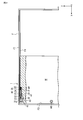
以下、本発明の一実施形態かかる可動体のアシスト装置1について、図1乃至図6を参照して説明する。各図中矢印X,Y,Zはそれぞれ互いに直交する3方向を示す。ここでは例えばX軸はスライド方向に、Y軸は幅方向に、Z軸は上下方向に、それぞれ沿っている。また、各図において説明のため、適宜構成を拡大、縮小または省略して示している。
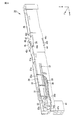
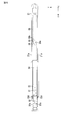
図1乃至図4に示すように、アシスト装置1は、可動体及び支持体のうち一方に設けられる当受体としてのストライカ10と、可動体及び支持体のうち他方に設けられるアシストユニット20と、を備えて構成される。なお、図3では内部構造の説明のためハウジング21の一部を切欠して示している。
本実施形態においては、例えば支持体は戸枠F、可動体は引き戸Mであり、引き戸Mにアシストユニット20が設けられ、戸枠Fにストライカ10が設けられる場合について例示する。
図1に示すように、戸枠Fの上部には収容部としての下方開口の引き戸溝F4がスライド方向に沿って設けられている。この引き戸溝F4に引き戸Mがスライド可能に収められている。また引き戸溝F4内には、引き戸Mに設けられたアシストユニット20の移動プレート42が配置され、この移動プレート42がY方向に移動することにより、アシストユニット20の引き戸溝F4内のY方向の位置が調整される。
引き戸Mの上端部には、スライド方向に沿ってアシストユニット20を収める溝M1が形成されている。溝M1は、スライド方向に沿って細長く形成されるとともに厚み方向に所定の幅を有した所定形状を成し下方に凹む上方開口となっている。溝M1のX方向一端側は開口しており、この溝M1にハウジング21が納められる。
なお、ここでは一枚の引き戸Mに着目し、左側が戸先側、右側が戸尻側とする。引き戸Mの戸先側である左端部には取っ手M2が形成されている。図1に示すように引き戸が戸先の枠F2に接していない状態を第1状態とし、図2に示すように戸先側の移動終了位置に移動されきって戸先の枠F2に当接した状態を第2状態とする。
アシスト装置1は、戸枠Fに設けられた当受体としてのストライカ10と、引き戸Mに設けられたアシストユニット20と、を備える。引き戸Mの溝M1のX方向一端部にアシストユニット20が配置される。
アシストユニット20は、溝M1内に設けられる基体としてのハウジング21と、ハウジング21のスライド方向一方側(図1中左側)の端部に収められ待機位置と引込位置との間でスライド移動可能に支持された当接体としてのラッチ22と、ラッチ22をハウジングに対してスライド方向他方側(図1中右側)に付勢する付勢機構23と、ラッチ22に連結されラッチ22のスライド移動に抵抗力を付与して緩衝する制動機構24と、ハウジング21に設けられた移動プレート42をY方向に移動することで溝M1におけるハウジング21のY方向の位置を調整する調整機構40と、を備えている。
引き戸溝F4には、左端から一定の位置にストライカ10が設けられている。ストライカ10は、上枠F1に取り付けられる板状の取付部材11と、Y軸に直交する面をなし上枠F1から下方に突出する係合部12と、を有して構成されている。係合部12がラッチ22のフック形状のキャッチャ32に捕捉され、ストライカ10とラッチ22とが係合する。係合部12は、引き戸Mの移動により、引き戸Mの上部の溝M1を通ってラッチ22に係合してアシストユニット20内に入り込み、あるいはアシストユニット20から出て解放されるようになっている。
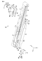
図3乃至6に示すように、ハウジング21は、側壁21a,21aを有し、上面開口でスライド方向に細長い箱状を成している。側壁21a,21aの間にはラッチ22が収まる上部室25aが形成され、上部室25aの一方側の端部は開口している。
図6に示すように、ハウジング21のスライド方向中央部分の所定位置には上面開口の一部を塞ぐ蓋体28が設けられている。蓋体28にはスライド方向に傾斜するガイドスリット29が形成されている。なお、図6においては説明のため調整機構40を省略して示している。ガイドスリット29は、Z方向及びY方向に傾斜するガイド路29aと、Y方向に端部まで延びる挿入路29bと、を備えている。このガイドスリット29に、移動プレート42のガイド突起48が係合して移動することにより、移動プレート42の移動方向が変換されて案内される。
ハウジング21の側壁21a,21aのスライド方向端部にはスリット27が設けられている。このスリット27には、ラッチ22に形成された軸部32dが回転可能に係合する。
ラッチ22は側壁21a,21aの間にスライド可能に配置されるラッチベース31とラッチベース31の先端に回動可能に連結されたキャッチャ32と、を有して構成される。
ラッチ22は、ハウジング21内においてスリット27の前端の待機位置とスリット27の後端の引込位置との間で移動可能であるとともに、待機位置においてR1及びR2方向に回動可能に支持されている。ラッチ22の先端に形成されたキャッチャ32はY方向に延びる軸部32dを中心として待機位置においてR1方向の回動によりストライカ10の係合部12を捕捉して係合可能であり、R2方向の回動により係合を解除してストライカ10を解放する。
ラッチベース31の後端部には、制動機構24が連結されている。制動機構24は、ハウジング21の上部室25a内に設けられたピストンダンパ33で構成されている。制動機構24は、内部にオイル等の流体が封入されたシリンダ34と、シリンダ34に往復動可能に収められたピストンに連結されるピストンロッド35と、を有し、ピストンロッド35の押し込み動作に対して流体の抵抗力を付与するように構成されている。制動機構24は、シリンダ34とピストンロッド35の一方がラッチ22の後端部に、他方がハウジング21に固定され、ラッチ22のスライド移動に抵抗力を作用させ可動体の移動を緩衝する機能を有している。
キャッチャ32の下部には、付勢機構としての引張コイルばね36の一端が連結され、常時引込方向に引張られている。ラッチ22によりストライカ10を捕捉した係合状態で、引張コイルばね36によりラッチ22を引込方向に引張ることにより、引き戸Mの移動が補助され、強制移動させられる。
調整機構40は、ハウジング21の一端部下方に設けられた操作部41と、ハウジング21の中途部の上面側でY方向に移動可能に設けられた移動プレート42(移動部)と、操作部41と移動プレート42とを連結するとともに操作部41の操作に応じてスライド方向に移動する伝達プレート43(伝達部)および連動部材44(伝達部)と、連動部材44のスライド方向の移動を移動プレート42のY方向の移動に変換する動作変換機構45と、を備えている。
操作部41は、ハウジング21の左端下部に設置され、溝M1内に配置されている。操作部41にはスライド方向に沿って雄ねじ46が保持されるねじ収容部47が設けられている。ねじ収容部47に操作手段としてのフランジ付き雄ねじ46が保持されており、この雄ねじ46は伝達プレート43の雌ねじ部43bに羅合されている。雄ねじ46はその基端に形成されたフランジ部46a(基端部)がねじ収容部47に係合して保持され、軸方向がスライド方向に沿うように回転可能に保持されている。操作部41の一端側にはねじ収容部47から外部に連通する連通孔47aが形成されており、この連通孔47を通じて雄ねじ46を回転させる操作が可能になっている。
移動プレート42(移動部)は、連動部材44に保持されてハウジング21の上面側に配置されている。移動プレート42は引き戸溝F4内に嵌合して配置されている。移動プレート42、矩形の板状に構成され、下面中央に動作変換部としてのガイド突起48を備えている。移動プレート42のスライド方向両端縁にはY方向に移動可能に連動部材44に係合する係合ガイド42cが形成されている。ガイド突起48は蓋体28のガイドスリット29に挿入され、ガイドスリット29に案内されて移動プレート42が斜めに移動するようになっている。
伝達プレート43は、ハウジング21の下部において下面に沿って左端下部から中途部に至ってスライド方向に延びる板金で形成されている。伝達プレート43の左端部はZ方向に沿うように折曲された折曲部43aを成し、操作部41の収容部47内に保持されている。折曲部43aの下端は返しが形成され、操作部41の収容部47に係止される。折曲部43aには雄ねじ46が羅装される雌ねじ部43bが形成されている。操作部41で雄ねじ46の羅合の状態を調節する操作がなされると、操作に応じて折曲部43aの位置がスライド方向において移動し、伝達プレート43が移動することで、X方向に移動する。伝達プレート43の他端側は幅狭の先端部43cが形成され、そのY方向両側の縁部分が折曲されて、連動部材44の下縁の孔44cに係止される爪部43dを形成している。
連動部材44は、ハウジング21の上面に対向する対向片44aと、ハウジング21の両側壁21a,21aを挟む一対の側片44b,44bと、を一体に有して断面視コ字状に構成されている。側片44b,44bの下端縁には伝達プレート43に係止される爪部43dが形成されている。側片44b、44bの下縁部がハウジング21の両側壁21a,21aの下縁部にスライド可能に係合する。
対向片44aは、移動プレートが配置される開口44dと、開口44dの両脇で移動プレート42の係合ガイド42cを移動可能に支持するガイドレール部44eと、を備えている。このガイドレール部44eに係合して、移動プレート42がY方向に相対移動可能に保持される。さらに、開口44dを通じて移動プレート42の下面のガイド突起48がハウジング21の蓋体28のガイドスリット29に係合している。
以上のように構成されたアシスト装置1の調整機構40では、溝M1の端部の開口に刃位置された操作部41の連通孔47aを通じてハウジング21の一端側から操作部41の雄ねじ46を回転させると、伝達プレート43が雄ねじ46の軸方向すなわちX方向に移動させられる。すると伝達プレート43の先端部43cに係合した連動部材が伝達プレート43とともにX方向に移動するとともに伝達プレート43に保持されたが移動プレート42もX方向に移動する。このとき、X方向及びY方向に傾斜して設けられたガイドスリット29によってガイド突起48が案内されることにより、移動プレート42はY方向にも移動することになる。以上により、ハウジング21に対する移動プレート42のY方向の位置調整が行われることで、ハウジング21の引き戸溝F4内のY方向の相対位置が調整され、戸枠Fに対するアシストユニット20及び引き戸Mの位置が調整される。
本実施形態にかかるアシスト装置1によれば調整機構40を備えたことにより単純な構成で位置調整が可能となる。上記実施形態にかかる調整機構40は、一端に設けられた操作部41の操作を伝達して中途部分に設けられた移動プレート42をY方向に移動させることができるため、一箇所の操作で調整が可能である。また低コスト及び省スペースで位置調整を実現可能である。さらに、一端が開口した溝M1にハウジング21を収容する構成により、引き戸Mの外側から溝M1を通じて操作部41を操作することができ、操作が容易である。また上記の調整機構40では、雄ねじ46を回転するだけの単純な操作で位置調整が可能となる。またハウジング21側に形成された斜めのガイドスリット29とガイド突起48によって単純な構成で移動方向を変換する動作変換機構を実現できる。
なお、本発明は前記実施の形態に限定されるものではなく、本発明の要旨を逸脱しない範囲で種々変形実施可能である。また、各部の具体的構成や材質等は上記実施形態に例示したものに限られるものではなく適宜変更可能である。
例えば上記実施形態においては、可動体側にアシストユニット20を備え、支持体側にストライカ10を設けた場合について例示したが、これに限られるものではなく、可動体側にストライカ10を、支持体側にアシストユニット20を、それぞれ設けてもよい。
また、上記実施形態においては可動体が引き戸Mである場合について例示したが、吊り戸、昇降式のスライドドア等、他の可動体にも本発明を適用可能である。
2011年3月14日に出願された日本特許出願第2011-055896号の明細書、特許請求の範囲、図面及び要約書の全内容をここに引用し、本発明の明細書の開示として、取り入れるものである。
2011年3月14日に出願された日本特許出願第2011-055896号の明細書、特許請求の範囲、図面及び要約書の全内容をここに引用し、本発明の明細書の開示として、取り入れるものである。
Claims (5)
- 支持体と前記支持体に相対的に移動する可動体とのいずれか一方側に設けられる当受体と、
前記支持体と前記可動体とのいずれか他方側に設けられた基体と、前記当受体と係合及び係合解除可能であり、前記基体に対して所定の移動経路に沿ってスライド移動可能に設けられた当接体と、
前記当接体を付勢する付勢機構と、
前記支持体と可動体との相対移動に沿う第1方向と交差する第2方向における前記基体の位置を調整する調整機構と、
を備え、
前記調整機構は、前記基体に設けられた操作部と、前記基体に設けられ前記第2方向に位置調整可能に設けられる移動部と、前記操作部と前記移動部を連結するとともに前記操作部における操作に応じて前記第1方向に移動する伝達部と、前記伝達部の第1方向の移動を前記2方向の移動に変換して前記移動部を前記第2方向に移動させる動作変換機構と、を備えたことを特徴とする可動体のアシスト装置。 - 前記操作部には、第1方向に沿って配置されるねじの基端部を保持する保持部が設けられ、
前記ねじの先端側に前記伝達部が連結され、
前記操作部における前記ねじの回転操作により、前記伝達部が第1方向に移動することを特徴とする請求項1記載の可動体のアシスト装置。 - 前記伝達部は前記基体の端部に設けられた操作部から前記基体の中途部に向かって延びる伝達プレートと、前記伝達プレートに係合して前記伝達プレートと共に前記第1方向に沿って前記スライドする連動部と、を備え、
前記移動部は前記連動部に対して第2方向に移動可能に支持される移動プレートを備え、
前記動作変換機構は前記移動プレートに設けられたガイド突起と、前記ガイド突起に係合し前記ガイド突起を前記第1方向及び前記第2方向に傾斜した経路に沿って案内するガイドスリットと、を備え、
前記伝達プレートが第1方向に移動すると、前記連動部に支持された前記移動プレートが、前記ガイドスリットに案内されて斜めに移動することにより、第2方向に移動することを特徴とする請求項1または2記載の可動体のアシスト装置。 - 前記支持体と前記可動体とのいずれか一方側に形成された収容部に前記移動プレートが配置された状態で前記移動プレートが前記基体に対して前記第2方向に移動することにより、前記収容部における前記基体の前記第2方向の位置が規制されることを特徴とする請求項1乃至3のいずれか記載の可動体のアシスト装置。
- 前記当接体のスライド移動に抵抗力を付与する制動機構を備えたことを特徴とする請求項1乃至4のいずれか記載の可動体のアシスト装置。
Priority Applications (2)
| Application Number | Priority Date | Filing Date | Title |
|---|---|---|---|
| KR1020137024764A KR20140004763A (ko) | 2011-03-14 | 2012-03-13 | 가동체의 어시스트 장치 |
| CN201280023295.3A CN103547760A (zh) | 2011-03-14 | 2012-03-13 | 可动体的辅助装置 |
Applications Claiming Priority (2)
| Application Number | Priority Date | Filing Date | Title |
|---|---|---|---|
| JP2011-055896 | 2011-03-14 | ||
| JP2011055896A JP2012193492A (ja) | 2011-03-14 | 2011-03-14 | 可動体のアシスト装置 |
Publications (1)
| Publication Number | Publication Date |
|---|---|
| WO2012124705A1 true WO2012124705A1 (ja) | 2012-09-20 |
Family
ID=46830772
Family Applications (1)
| Application Number | Title | Priority Date | Filing Date |
|---|---|---|---|
| PCT/JP2012/056454 Ceased WO2012124705A1 (ja) | 2011-03-14 | 2012-03-13 | 可動体のアシスト装置 |
Country Status (4)
| Country | Link |
|---|---|
| JP (1) | JP2012193492A (ja) |
| KR (1) | KR20140004763A (ja) |
| CN (1) | CN103547760A (ja) |
| WO (1) | WO2012124705A1 (ja) |
Families Citing this family (1)
| Publication number | Priority date | Publication date | Assignee | Title |
|---|---|---|---|---|
| CN104727703B (zh) * | 2015-04-02 | 2016-08-31 | 伍志勇 | 用于滑动门的锁定调节机构 |
Citations (1)
| Publication number | Priority date | Publication date | Assignee | Title |
|---|---|---|---|---|
| JP2007309088A (ja) * | 2006-04-20 | 2007-11-29 | Nifco Inc | 可動体の自走往動機構、引き戸、およびスペーサ具 |
Family Cites Families (5)
| Publication number | Priority date | Publication date | Assignee | Title |
|---|---|---|---|---|
| EP2014856A4 (en) * | 2006-04-20 | 2014-03-05 | Nifco Inc | MOVEMENT MECHANISM AUTOPROPULSED FORWARD OF MOBILE BODY, SLIDING DOOR AND SPACER DEVICE |
| JP5105629B2 (ja) * | 2006-11-13 | 2012-12-26 | 株式会社ニフコ | 摺動補助機構及び引込ユニット |
| JP5093881B2 (ja) * | 2006-11-13 | 2012-12-12 | 株式会社ニフコ | 摺動補助機構及び引込ユニット |
| JP2010112012A (ja) * | 2008-11-04 | 2010-05-20 | Nifco Inc | 可動体の往動機構 |
| JP2011006872A (ja) * | 2009-06-24 | 2011-01-13 | Nifco Inc | 摺動補助機構及び引込ユニット |
-
2011
- 2011-03-14 JP JP2011055896A patent/JP2012193492A/ja active Pending
-
2012
- 2012-03-13 CN CN201280023295.3A patent/CN103547760A/zh active Pending
- 2012-03-13 WO PCT/JP2012/056454 patent/WO2012124705A1/ja not_active Ceased
- 2012-03-13 KR KR1020137024764A patent/KR20140004763A/ko not_active Ceased
Patent Citations (1)
| Publication number | Priority date | Publication date | Assignee | Title |
|---|---|---|---|---|
| JP2007309088A (ja) * | 2006-04-20 | 2007-11-29 | Nifco Inc | 可動体の自走往動機構、引き戸、およびスペーサ具 |
Also Published As
| Publication number | Publication date |
|---|---|
| CN103547760A (zh) | 2014-01-29 |
| JP2012193492A (ja) | 2012-10-11 |
| KR20140004763A (ko) | 2014-01-13 |
Similar Documents
| Publication | Publication Date | Title |
|---|---|---|
| JP5907693B2 (ja) | 可動体のアシスト装置 | |
| JP4806609B2 (ja) | 引き込みユニット | |
| JP4951765B2 (ja) | 延長ガイドのための閉鎖および保持用の装置 | |
| JPWO2011021414A1 (ja) | 戸開閉装置 | |
| CN103313628B (zh) | 用于可移动家具部件的打开和闭合装置及弹出装置 | |
| JP2008297861A (ja) | 引き戸の走行制御装置 | |
| JP2011021414A (ja) | 可動体のアシスト装置 | |
| JP6732397B2 (ja) | 引込み装置及び引込み装置セット | |
| CN103298371B (zh) | 用于可移动家具部件的打开和闭合装置 | |
| JP2006299578A (ja) | 引戸又は引出しの引込み装置 | |
| WO2012124705A1 (ja) | 可動体のアシスト装置 | |
| JP4756577B2 (ja) | 緩衝装置 | |
| JP5926949B2 (ja) | 可動体のアシスト装置 | |
| WO2013047518A1 (ja) | 可動体のアシスト装置 | |
| CN103025203A (zh) | 移动抑制装置 | |
| US12006747B2 (en) | Sliding door device | |
| KR101481350B1 (ko) | 차량용 도어 아웃사이드 핸들 | |
| JP6276643B2 (ja) | スイッチ装置および駆動装置 | |
| JP2012193490A (ja) | 可動体のアシスト装置 | |
| JP5013610B2 (ja) | 吊戸ランナの隙間閉鎖機構付き軸受けストッパー | |
| JP5909409B2 (ja) | 位置調整装置 | |
| JP2012193493A (ja) | 可動体のアシスト装置 | |
| JP6304103B2 (ja) | 回動装置 | |
| JP5653742B2 (ja) | 開閉体閉止装置 | |
| JP3154600U (ja) | 間仕切り装置の開閉装置 |
Legal Events
| Date | Code | Title | Description |
|---|---|---|---|
| 121 | Ep: the epo has been informed by wipo that ep was designated in this application |
Ref document number: 12757184 Country of ref document: EP Kind code of ref document: A1 |
|
| NENP | Non-entry into the national phase |
Ref country code: DE |
|
| ENP | Entry into the national phase |
Ref document number: 20137024764 Country of ref document: KR Kind code of ref document: A |
|
| 122 | Ep: pct application non-entry in european phase |
Ref document number: 12757184 Country of ref document: EP Kind code of ref document: A1 |