WO2012124316A1 - 赤外線撮像装置 - Google Patents
赤外線撮像装置 Download PDFInfo
- Publication number
- WO2012124316A1 WO2012124316A1 PCT/JP2012/001767 JP2012001767W WO2012124316A1 WO 2012124316 A1 WO2012124316 A1 WO 2012124316A1 JP 2012001767 W JP2012001767 W JP 2012001767W WO 2012124316 A1 WO2012124316 A1 WO 2012124316A1
- Authority
- WO
- WIPO (PCT)
- Prior art keywords
- infrared
- optical system
- mirror
- imaging device
- secondary mirror
- Prior art date
- Legal status (The legal status is an assumption and is not a legal conclusion. Google has not performed a legal analysis and makes no representation as to the accuracy of the status listed.)
- Ceased
Links
Images




Classifications
-
- G—PHYSICS
- G02—OPTICS
- G02B—OPTICAL ELEMENTS, SYSTEMS OR APPARATUS
- G02B13/00—Optical objectives specially designed for the purposes specified below
- G02B13/14—Optical objectives specially designed for the purposes specified below for use with infrared or ultraviolet radiation
-
- G—PHYSICS
- G02—OPTICS
- G02B—OPTICAL ELEMENTS, SYSTEMS OR APPARATUS
- G02B17/00—Systems with reflecting surfaces, with or without refracting elements
- G02B17/08—Catadioptric systems
- G02B17/0804—Catadioptric systems using two curved mirrors
- G02B17/0808—Catadioptric systems using two curved mirrors on-axis systems with at least one of the mirrors having a central aperture
-
- G—PHYSICS
- G02—OPTICS
- G02B—OPTICAL ELEMENTS, SYSTEMS OR APPARATUS
- G02B23/00—Telescopes, e.g. binoculars; Periscopes; Instruments for viewing the inside of hollow bodies; Viewfinders; Optical aiming or sighting devices
- G02B23/02—Telescopes, e.g. binoculars; Periscopes; Instruments for viewing the inside of hollow bodies; Viewfinders; Optical aiming or sighting devices involving prisms or mirrors
-
- H—ELECTRICITY
- H04—ELECTRIC COMMUNICATION TECHNIQUE
- H04N—PICTORIAL COMMUNICATION, e.g. TELEVISION
- H04N23/00—Cameras or camera modules comprising electronic image sensors; Control thereof
- H04N23/20—Cameras or camera modules comprising electronic image sensors; Control thereof for generating image signals from infrared radiation only
Definitions
- the present invention relates to an infrared imaging device.
- the exit pupil of the infrared optical system is matched with the cold aperture that is an aperture stop (aperture matching), and S An image with a good / N (signal-to-noise ratio) is obtained.
- JP-A-10-206986 Japanese Patent Application Laid-Open No. 9-113797
- the infrared imaging device described in Patent Document 1 has a configuration in which infrared rays from other than the object to be detected, which becomes detection noise, are shielded by a central shielding portion provided at the opening portion of the cold door patcher.
- a central shielding portion provided at the opening portion of the cold door patcher.
- the central shielding part is a special structure attached to the opening of the cold door patcher through a thin arm part, it is difficult to uniformly cool the central shielding part to the same temperature as its peripheral part, There is a possibility that the S / N deterioration of the obtained image may occur.
- the infrared imaging device described in Patent Document 2 causes detection noise by disposing an objective optical system that forms an intermediate image and a re-imaging optical system that is located on the image side of the intermediate image so as to be decentered from each other. Unnecessary infrared rays are prevented from entering the center of the aperture and reaching the detector.
- the objective optical system since the objective optical system requires an off-axis optical design, it is difficult to correct aberrations during the design, and the effective diameter of the lens and mirror is greatly increased with respect to the entrance pupil diameter. May increase the size of the apparatus.
- the present invention has been made in view of such a problem, and includes an objective optical system having a non-passing portion where light from a test object does not pass in the vicinity of the optical axis in a state where aperture matching is achieved.
- Infrared imaging that can prevent infrared rays unnecessary for imaging from objects other than the test object from being mixed into the infrared detector by using a cold door aperture with a simple circular opening that does not have a special shape, without increasing the size of the device
- An object is to provide an apparatus.
- an infrared optical system that collects infrared rays from a test object, an infrared imaging device that receives infrared rays from the infrared optical system, and A cold door aperture that prevents an infrared ray unnecessary for imaging from other than the object to be detected from entering the infrared imaging device, and the infrared optical system includes a main mirror disposed opposite to the optical axis.
- An objective optical system that sequentially reflects infrared rays from the test object by the primary mirror and the secondary mirror to form an intermediate image of the test object, and the intermediate formed by the objective optical system.
- an infrared imaging device having a re-imaging optical system that re-forms an image on the infrared imaging device, and a non-passing portion where infrared rays from the object to be examined do not pass in a center portion of the secondary mirror
- the center of the secondary mirror corresponding to the non-passing part An infrared imaging apparatus is provided which is characterized in that it is formed in a concave shape which satisfies the following condition. L / 1.2 ⁇ R ⁇ 1.5L However, R: absolute value of the radius of curvature of the central part of the secondary mirror corresponding to the non-passing part, L: Distance from the intermediate image forming position to the center of the secondary mirror corresponding to the non-passing portion.
- a special apparatus can be used without increasing the size of the apparatus. It is possible to provide an infrared imaging apparatus capable of preventing infrared rays unnecessary for imaging from other than the object to be detected from being mixed into the infrared detector by using a cold door aperture having a simple circular opening which is not a shape.
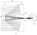
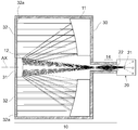
- FIG. 1 is a diagram for explaining an infrared imaging device (having a Cassegrain type objective optical system) according to the present embodiment, showing a cross-sectional configuration thereof and an optical path diagram of a luminous flux in a ring shape following the opening of a main mirror.
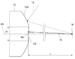
- the shape of the secondary mirror and the state where the axial light beam is reflected by the non-passing portion of the infrared light from the test object at the center of the secondary mirror are shown.
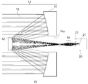
- It is a figure explaining the infrared imaging device which concerns on said embodiment, and shows the optical path figure of the light beam in an opening center part.
- FIG. 2 shows an optical path diagram of a light beam at the center of an aperture in a comparative infrared imaging device in which aperture matching is achieved and there is a non-passing portion of infrared rays from a test object at the center of the secondary mirror.
- the infrared imaging device includes an infrared optical system 10 and an infrared detector 20.
- the infrared optical system 10 is for collecting heat radiated from an object to be examined (not shown), that is, infrared rays, and includes a primary mirror 11 and a secondary mirror 12 which are arranged to face each other along the optical axis AX.
- An objective optical system 13 that sequentially reflects the infrared rays from the object to be examined by the primary mirror 11 and the secondary mirror 12 to form an intermediate image of the object to be examined, and the intermediate image formed by the objective optical system 13 ( And a re-imaging optical system 14 that re-forms on the infrared imaging device 21 (in the infrared detector 20).
- the infrared detector 20 is disposed at a position where infrared rays from the object to be collected are collected by the infrared optical system 10, and an infrared imaging device 21 that receives infrared rays from the infrared optical system 10, and the infrared optical system 10.
- the cold door patcher 22 is disposed between the infrared imaging element 21 and the infrared imaging element 21 so as to prevent unnecessary infrared rays from entering from the periphery (side or oblique) of the imaging surface of the infrared imaging element 21.
- a cooling device (not shown) that cools the infrared imaging element 21 to a low temperature (for example, about the temperature of liquid nitrogen) and removes infrared rays emitted from the infrared imaging element 21 as much as possible.
- the cold door aperture 22 has a simple circular opening at the center, and the position and the size of the opening diameter are the position and the size of the exit pupil of the infrared optical system 10 (re-imaging optical system 14). It is designed to match the (exit pupil diameter), that is, to achieve aperture matching. By taking aperture matching in this way, it is possible to efficiently suppress that infrared light unnecessary for imaging other than the test object is incident on the infrared detector 20 and to obtain a good infrared image from the test object. I can do it.
- heat (infrared rays) radiated from the test object is sequentially reflected by the primary mirror 11 and the secondary mirror 12 constituting the objective optical system 13 to form an intermediate image of the test object.
- the thermal image (infrared image) of the object to be inspected is obtained by condensing the light from the intermediate image again on the infrared imaging element 21 (via the cold aperture 22) by the re-imaging optical system 14. It has come to be obtained.
- the objective optical system 13 includes a primary mirror 11 that is a concave reflecting mirror (with a concave surface facing the secondary mirror 12) having an opening 11a in the center, and a secondary mirror that is a convex reflecting mirror (with a convex surface facing the primary mirror 11).
- 12 is a so-called Cassegrain type optical system.
- the light beam traveling from the primary mirror 11 to the secondary mirror 12 becomes an annular light beam 15 following the opening 11a of the primary mirror 11, there is a portion in the vicinity of the optical axis AX where there is no light beam from the test object. To do. That is, a non-passing portion 12 f where the infrared rays from the test object that has become the annular light flux 15 as described above does not pass exists at the center of the secondary mirror 12.
- the non-passing portion 12f present at the center of the secondary mirror 12 is formed in a concave shape that satisfies the following conditional expression (1). That is, the reflecting surface of the secondary mirror 12 has two different shapes including the concave reflecting surface 12f and the convex reflecting surface 12A.
- R absolute value of the radius of curvature of the central portion of the secondary mirror 12 corresponding to the non-passing portion 12f
- L Distance from the intermediate image formation position M to the center of the secondary mirror 12 corresponding to the non-passing portion 12f.
- the lower limit is preferably set to L / 1.1 in order to better exhibit the effect of satisfying conditional expression (1).
- the upper limit value is preferably set to 1.2L.
- the concave non-passing portion 12f of the sub mirror 12 is arranged at a position conjugate with the exit pupil of the infrared optical system 10 (re-imaging optical system 14).
- the concave non-passing portion 12f of the secondary mirror 12f It is also conjugate with the aperture 22.
- the central part of the secondary mirror 12 which is a convex mirror has such a special shape, the light beam (axial light beam) 16 passing through the central part of the opening 11a of the primary mirror 11 is not concavely shaped on the secondary mirror 12. The light is reflected by the passage portion 12f and returns directly to the center of the opening 11a. Therefore, the optical path diagram of the light flux at the center of the aperture 11a is as shown in FIG. 3, and the light beam emitted from the center point O of the imaging surface of the infrared imaging device 21 is reflected by the concave non-passing portion 12f of the secondary mirror 12.
- the light beam emitted from the point A on the imaging surface is reflected by the concave non-passing portion 12f of the sub mirror 12 and returns to the point A ′ that is symmetric with respect to the optical axis. That is, the light beam existing at the center of the opening 11a forms an image on the imaging surface itself of the infrared imaging element 21 by reflection at the concave non-passing portion 12f of the sub mirror 12.
- the light beam at the center of the aperture 11a is different from the optical system of the comparative example as shown in FIG. 11 (to be described later) (that is, not emitted from the main mirror 11 or its surrounding barrel), and is all infrared. It comes from the inside of the detector 20. However, since the inside of the infrared detector 20 is cooled to a very low temperature by the cooling device (not shown) as described above, unnecessary infrared rays at the center of the opening 11a are not detected.
- the diameter of the concave non-passing portion 12f of the secondary mirror 12 is d1 (see FIG. 2), the opening diameter of the opening 11a of the primary mirror 11 is D1, and the effective diameter D2 of the primary mirror 11 is set.
- the non-passing portion 12f is formed by forming the non-passing portion 12f through which the infrared rays from the test object at the center of the secondary mirror 12 do not pass in a concave shape. It is possible to prevent unnecessary infrared rays from being mixed into the infrared imaging element 21 and to allow only infrared rays from the object to be detected to enter the infrared imaging element 21. As a result, noise incident on the infrared detector 20 can be suppressed, and the detection sensitivity of the infrared detector 20 can be improved.
- the present invention is not limited to the first embodiment, and various developments are possible.
- the same members as those used in the infrared imaging device of the first embodiment or those having the same function are denoted by the same reference numerals and description thereof is omitted.
- the infrared imaging apparatus according to the second embodiment will be described with reference to FIGS.
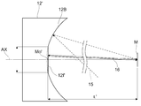
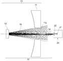
- a Cassegrain type optical system in which the secondary mirror 12 is a convex mirror is used as the objective optical system 13, but as shown in FIG. 4, in the infrared imaging apparatus according to the present embodiment, the objective optical system is used.
- a Gregory type optical system 13 in which the secondary mirror 12 'is a concave mirror. In this case, an infrared imaging device essentially equivalent to the first embodiment can be obtained.
- the light beam traveling from the primary mirror 11 to the secondary mirror 12 becomes the annular light beam 15 following the opening 11a of the primary mirror 11, and therefore, near the optical axis AX, the light beam from the object to be inspected.
- the non-passing portion 12f ′ present at the center of the secondary mirror 12 ′ is formed in a concave shape that satisfies the following conditional expression (1) ′, as in the above-described embodiment. That is, the reflecting surface of the secondary mirror 12 'has two concave reflecting surfaces 12f' and 12B having different curvature radii.
- R ′ absolute value of the radius of curvature of the central portion of the secondary mirror 12 ′ corresponding to the non-passing portion 12f ′
- L ′ distance from the formation position M of the intermediate image to the center of the secondary mirror 12 ′ corresponding to the non-passing portion 12f ′.
- the lower limit value is preferably set to L ′ / 1.1 in order to better exhibit the effect of satisfying conditional expression (1) ′.
- the upper limit value is preferably set to 1.2 L'.
- the non-passing portion 12f ′ existing in the central portion of the secondary mirror 12 ′ has an intermediate image formation position M on the optical axis AX as the center of curvature.
- the concave non-passing portion 12f ′ of the secondary mirror 12 ′ is arranged at a position conjugate with the exit pupil of the infrared optical system 10 (re-imaging optical system 14). Since the position of the exit pupil of the infrared optical system 10 (re-imaging optical system 14) coincides with the position of the cold door aperture 22, the concave non-passing portion 12f 'of the secondary mirror 12f' is the cold door aperture 22. Is also conjugate.
- the light beam (axial light beam) 16 passing through the central part of the opening 11a of the primary mirror 11 does not pass through the concave shape of the secondary mirror 12 ′.
- the light is reflected by the portion 12f ′ and returns directly to the center of the opening 11a. Therefore, the optical path diagram of the light flux at the center of the opening 11a is as shown in FIG. 6, and the light beam emitted from the center point O of the imaging surface of the infrared imaging device 21 is at the concave non-passing portion 12f ′ of the secondary mirror 12 ′.
- the reflected light returns to the point O, and the light beam emitted from the point A on the imaging surface is reflected by the concave non-passing portion 12f ′ of the secondary mirror 12 ′ and returns to the point A ′ that is symmetric with respect to the optical axis. That is, the light beam existing in the central portion of the opening 11a forms an image on the imaging surface itself of the infrared imaging element 21 by reflection at the concave non-passing portion 12f ′ of the sub mirror 12 ′.
- the light beam at the center of the opening 11a is all generated from the inside of the infrared detector 20, but since the inside of the infrared detector 20 is cooled to a very low temperature by a cooling device (not shown), the opening Unnecessary infrared rays in the center of 11a are not detected. Therefore, the same effect as the infrared imaging device of the above embodiment can be obtained.
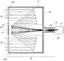
- the infrared imaging device is a mirror having an opening 30a for guiding infrared rays from a test object (not shown) to the infrared optical system 10 at one end. It is stored in the cylinder 30.
- the secondary mirror 12 is supported in the lens barrel 30 by spiders 32 that extend radially from a pedestal 31 that fixes the secondary mirror 12.
- the concave non-passing portion 12 f is provided at the center of the secondary mirror 12, so that unnecessary infrared light at the center of the opening 11 a is not mixed into the infrared detector 20.
- the spider 32 also shields the light flux, so that unnecessary infrared radiation from the spider 32 becomes a problem.
- the spider 32 is configured such that the outer surface 32a on the side of the primary mirror 11 is a plane that is perpendicular to the optical axis AX and has a high reflectance with respect to infrared rays. desirable.
- the spider 32 is a parallel plate in which each surface is arranged in a direction orthogonal to the optical axis AX of the primary mirror 11, and the outer surface 32a on the primary mirror 11 side has a reflectance with respect to infrared rays. It is a high mirror surface. According to this configuration, the optical path diagram of the light beam shielded by the spider 32 is as shown in FIG.
- the light beam emitted from the center point O of the imaging surface of the infrared imaging device 21 is the secondary mirror 12 and the primary mirror 11.
- the primary mirror 11 and the secondary mirror 12 are sequentially passed back to the point O.
- the light beam emitted from the point A on the imaging surface is reflected by the mirror surface 32a on the primary mirror 11 side of the spider 32 through the secondary mirror 12 and the primary mirror 11 in this order, and then the primary mirror 11 and the secondary mirror 12 are moved.
- the process returns to the point A ′ that is symmetrical with respect to the optical axis. That is, the light beam shielded by the spider 32 forms an image on the imaging surface itself of the infrared imaging element 21 by reflection at the mirror surface 32a of the spider 32 on the primary mirror 11 side.
- the light beam shielded by the spider 32 is generated from the inside of the infrared detector 20 in the same manner as the light beam at the center of the opening 11a.
- the inside of the infrared detector 20 is cooled to an extremely low temperature by the cooling device (not shown) as described above, unnecessary infrared rays from the spider 32 are not detected.
- the size of the apparatus is increased while the objective optical system having the non-passing portion where the light from the test object does not pass in the vicinity of the optical axis in a state where the aperture is aligned.
- the center part of the secondary mirror corresponding to the non-passing part is formed in a concave shape, which is unnecessary for imaging from the non-passing part.
- An infrared imaging device with good detection sensitivity can be provided without infrared rays being mixed into the infrared detector.
- the infrared imaging apparatus of the comparative example mainly includes an infrared optical system 10 and an infrared detector 20.
- the infrared optical system 10 includes an objective optical system 13 and a re-imaging optical system 14.
- the infrared optical system 10 condenses heat radiated from an object to be examined (not shown), that is, infrared rays, and the imaging device of the infrared detector 20. An image is formed on the surface 21.
- the infrared detector 20 is disposed at a position where infrared rays from the object to be collected are collected by the infrared optical system 10, and has a plurality of light receiving elements on the imaging element surface 21.
- the infrared detector 10 removes the influence of infrared rays (for example, self-radiation of the lens barrel) unnecessary for imaging radiated from other than the test object.
- a cold door aperture 22 having an opening through which the infrared light collected by the infrared optical system 10 passes is disposed between the image pickup device 21 and the infrared image pickup device 21 so as to surround the image pickup device surface 21 (side or oblique). The unnecessary door light is blocked, the cold door aperture 22 and the infrared detector 20 are cooled to a low temperature (almost liquid nitrogen temperature), and the infrared rays radiated from them are removed as much as possible.
- the opening provided in the cold door aperture 22 is designed so that the position and size (exit pupil diameter) of the exit pupil of the infrared optical system 10 coincide with each other. It is called “consistent state”. In this way, the cold door aperture 22 takes aperture alignment with the exit pupil of the infrared optical system 10 so that the infrared detector 20 efficiently uses infrared light unnecessary for imaging other than the test object of the infrared optical system 10. It can suppress well, and can take in only the infrared light of the test object.
- the infrared optical system 10 is configured, for example, a primary mirror 11 having an opening 11a at the center, and a secondary mirror 12 that directs infrared rays reflected by the primary mirror 11 toward the opening 11a of the primary mirror 11;
- the Cassegrain-type objective optical system 13 constituted by the above when the infrared light from the object to be examined is reflected by the main mirror 11, it becomes an annular luminous flux 15 that follows the opening 11a of the main mirror 11, and is hollow. It becomes the state of. That is, as shown in FIG.
- the light beam (axial light beam) 16 at the center of the opening 11a is an infrared ray that is unnecessary for imaging from other than the test object radiated from the opening 11a of the primary mirror 11 and its periphery. . Even if aperture matching is performed in this way, if infrared light unnecessary for imaging occurs in the center of the opening 11a, the mixed infrared light is detected as noise as it is, and the S / N (signal-to-noise ratio) of the obtained image is detected. ).
- the amount of such detection noise varies depending on the angle of view of the luminous flux.
- the detection noise on the optical axis has a high ratio in which the source is inside the infrared detector 10, but the infrared imaging device cools the infrared detector 10 as described above and removes unnecessary infrared light as much as possible. Therefore, it tends to be smaller than a light beam having a field angle outside the optical axis.
- the detection noise has a gradient at the central portion and the peripheral portion of the infrared detector 20, and a so-called Narcissus phenomenon in which an image like the cold door aperture 22 is visible at the central portion of the image pickup device surface 21 may occur. .
- the center portion of the secondary mirror is formed in a concave shape while providing an objective optical system having a non-passing portion in a state in which the aperture is aligned.
Landscapes
- Physics & Mathematics (AREA)
- General Physics & Mathematics (AREA)
- Optics & Photonics (AREA)
- Engineering & Computer Science (AREA)
- Multimedia (AREA)
- Signal Processing (AREA)
- Health & Medical Sciences (AREA)
- Toxicology (AREA)
- Astronomy & Astrophysics (AREA)
- Lenses (AREA)
- Telescopes (AREA)
Abstract
Description
L/1.2 < R < 1.5L
但し、
R:前記不通過部分に対応する前記副鏡の中心部の曲率半径の絶対値、
L:前記中間像形成位置から前記不通過部分に対応する前記副鏡の中心部までの距離。
但し、
R:不通過部分12fに対応する副鏡12の中心部の曲率半径の絶対値、
L:中間像の形成位置Mから不通過部分12fに対応する副鏡12の中心部までの距離。
但し、
R´:不通過部分12f´に対応する副鏡12´の中心部の曲率半径の絶対値、
L´:中間像の形成位置Mから不通過部分12f´に対応する副鏡12´の中心部までの距離。
10 赤外光学系
11 主鏡
11a 主鏡の開口
12 副鏡
12f 副鏡中心部の不通過部分
13 対物光学系
14 再結像光学系
20 赤外線検出器
21 赤外線撮像素子
22 コールドアパチャー
30 鏡筒
30a 鏡筒の開口
31 台座
32 スパイダー
AX 光軸
Claims (5)
- 被検物体からの赤外線を集光する赤外光学系と、前記赤外光学系からの赤外線を受光する赤外線撮像素子と、前記赤外線撮像素子へ前記被検物体以外からの撮像に不要な赤外線が入射することを防ぐコールドアパチャーとを有し、
前記赤外光学系は、光軸に沿って対向配置された主鏡と副鏡とを含み、前記被検物体からの赤外線を前記主鏡及び前記副鏡で順次反射し前記被検物体の中間像を形成する対物光学系と、前記対物光学系により形成された前記中間像を前記赤外線撮像素子上に再形成する再結像光学系とを有し、
前記副鏡の中心部には前記被検物体からの赤外線が通過しない不通過部分が存在する赤外線撮像装置において、
前記不通過部分に対応する前記副鏡の中心部は、以下の条件式を満足する凹面状に形成されていることを特徴とする赤外線撮像装置。
L/1.2 < R < 1.5L
但し、
R:前記不通過部分に対応する前記副鏡の中心部の曲率半径の絶対値、
L:前記中間像形成位置から前記不通過部分に対応する前記副鏡の中心部までの距離。 - 前記不通過部分に対応する前記副鏡の中心部は、前記対物光学系による前記光軸上の前記中間像形成位置を曲率中心とする凹面状に形成されていることを特徴とする請求項1に記載の赤外線撮像装置。
- 前記副鏡の前記不通過部分は、前記赤外光学系の射出瞳と共役関係にあることを特徴とする請求項1又は2に記載の赤外線撮像装置。
- 前記赤外光学系の射出瞳の位置は、前記コールドアパチャーの位置と一致していることを特徴とする請求項1~3のいずれか一項に記載の赤外線撮像装置。
- 前記赤外線撮像装置は、一端に前記被検物体からの赤外線を前記赤外光学系へと導くための開口が形成された鏡筒内に収納されており、
前記鏡筒は前記開口に前記副鏡を固定保持するスパイダーを有し、
前記スパイダーは、前記主鏡側の外面が、前記光軸に対して垂直な平面であり、且つ、赤外線に対して反射率の高い鏡面で構成されていることを特徴とする請求項1~4のいずれか一項に記載の赤外線撮像装置。
Priority Applications (2)
| Application Number | Priority Date | Filing Date | Title |
|---|---|---|---|
| JP2013504565A JP5534490B2 (ja) | 2011-03-16 | 2012-03-14 | 赤外線撮像装置 |
| US14/005,272 US20140002669A1 (en) | 2011-03-16 | 2012-03-14 | Infrared image capture device |
Applications Claiming Priority (2)
| Application Number | Priority Date | Filing Date | Title |
|---|---|---|---|
| JP2011-058478 | 2011-03-16 | ||
| JP2011058478 | 2011-03-16 |
Publications (1)
| Publication Number | Publication Date |
|---|---|
| WO2012124316A1 true WO2012124316A1 (ja) | 2012-09-20 |
Family
ID=46830407
Family Applications (1)
| Application Number | Title | Priority Date | Filing Date |
|---|---|---|---|
| PCT/JP2012/001767 Ceased WO2012124316A1 (ja) | 2011-03-16 | 2012-03-14 | 赤外線撮像装置 |
Country Status (3)
| Country | Link |
|---|---|
| US (1) | US20140002669A1 (ja) |
| JP (1) | JP5534490B2 (ja) |
| WO (1) | WO2012124316A1 (ja) |
Cited By (4)
| Publication number | Priority date | Publication date | Assignee | Title |
|---|---|---|---|---|
| CN103345051A (zh) * | 2013-07-02 | 2013-10-09 | 中国科学院长春光学精密机械与物理研究所 | 双模折反射式共探测器成像系统 |
| CN104035197A (zh) * | 2014-06-12 | 2014-09-10 | 电子科技大学 | 一种折反式太赫兹波成像系统 |
| CN104932094A (zh) * | 2015-06-02 | 2015-09-23 | 湖北久之洋红外系统股份有限公司 | 用于面阵全景扫描的中波红外成像镜头 |
| CN106405807A (zh) * | 2016-12-07 | 2017-02-15 | 中国科学院长春光学精密机械与物理研究所 | 一种双视场双焦距红外光学系统 |
Families Citing this family (4)
| Publication number | Priority date | Publication date | Assignee | Title |
|---|---|---|---|---|
| CN105892049B (zh) * | 2016-06-30 | 2017-02-08 | 华北水利水电大学 | 一种大口径二次成像r‑c光学系统 |
| US11320638B2 (en) * | 2018-08-29 | 2022-05-03 | Viettel Group | Catadioptric system for mid-wave thermal imaging equipment |
| CN114442261A (zh) * | 2020-10-30 | 2022-05-06 | 华为技术有限公司 | 潜望式光学成像系统、摄像模组和电子装置 |
| CN120686455B (zh) * | 2025-07-28 | 2026-07-07 | 中国科学院上海技术物理研究所 | 一种同轴折反式红外低温光学系统及其装调测试方法 |
Citations (4)
| Publication number | Priority date | Publication date | Assignee | Title |
|---|---|---|---|---|
| JPS5768811A (en) * | 1980-10-17 | 1982-04-27 | Matsushita Electric Ind Co Ltd | Beam condensing device |
| JPH0756089A (ja) * | 1993-08-13 | 1995-03-03 | Nec Corp | 光空間伝播装置 |
| JPH08129135A (ja) * | 1994-10-31 | 1996-05-21 | Canon Inc | 光通信用の光学装置 |
| JPH10206986A (ja) * | 1997-01-27 | 1998-08-07 | Topcon Corp | 赤外線光学装置 |
Family Cites Families (2)
| Publication number | Priority date | Publication date | Assignee | Title |
|---|---|---|---|---|
| JPH0718978B2 (ja) * | 1987-07-15 | 1995-03-06 | 三菱電機株式会社 | 反射鏡スパイダ支持構造体 |
| IL113350A (en) * | 1995-04-12 | 1998-06-15 | State Rafaelel Ministry Of Def | Catadioptric optics working staring detector system |
-
2012
- 2012-03-14 US US14/005,272 patent/US20140002669A1/en not_active Abandoned
- 2012-03-14 WO PCT/JP2012/001767 patent/WO2012124316A1/ja not_active Ceased
- 2012-03-14 JP JP2013504565A patent/JP5534490B2/ja active Active
Patent Citations (4)
| Publication number | Priority date | Publication date | Assignee | Title |
|---|---|---|---|---|
| JPS5768811A (en) * | 1980-10-17 | 1982-04-27 | Matsushita Electric Ind Co Ltd | Beam condensing device |
| JPH0756089A (ja) * | 1993-08-13 | 1995-03-03 | Nec Corp | 光空間伝播装置 |
| JPH08129135A (ja) * | 1994-10-31 | 1996-05-21 | Canon Inc | 光通信用の光学装置 |
| JPH10206986A (ja) * | 1997-01-27 | 1998-08-07 | Topcon Corp | 赤外線光学装置 |
Cited By (4)
| Publication number | Priority date | Publication date | Assignee | Title |
|---|---|---|---|---|
| CN103345051A (zh) * | 2013-07-02 | 2013-10-09 | 中国科学院长春光学精密机械与物理研究所 | 双模折反射式共探测器成像系统 |
| CN104035197A (zh) * | 2014-06-12 | 2014-09-10 | 电子科技大学 | 一种折反式太赫兹波成像系统 |
| CN104932094A (zh) * | 2015-06-02 | 2015-09-23 | 湖北久之洋红外系统股份有限公司 | 用于面阵全景扫描的中波红外成像镜头 |
| CN106405807A (zh) * | 2016-12-07 | 2017-02-15 | 中国科学院长春光学精密机械与物理研究所 | 一种双视场双焦距红外光学系统 |
Also Published As
| Publication number | Publication date |
|---|---|
| JP5534490B2 (ja) | 2014-07-02 |
| JPWO2012124316A1 (ja) | 2014-07-17 |
| US20140002669A1 (en) | 2014-01-02 |
Similar Documents
| Publication | Publication Date | Title |
|---|---|---|
| JP5534490B2 (ja) | 赤外線撮像装置 | |
| US7002154B2 (en) | Optical system for a wide field of view staring infrared sensor having improved optical symmetry | |
| US9377612B2 (en) | IR microscope with image field curvature compensation, in particular with additional illumination optimization | |
| JPS58190916A (ja) | 赤外望遠鏡用の冷却された視野光学系 | |
| JPH03148044A (ja) | 顕微分光測定装置 | |
| JPH02157808A (ja) | 放射ビーム収束装置 | |
| KR20210118821A (ko) | 다중 채널 근접 영상화 디바이스 | |
| RU2606699C1 (ru) | Двухканальная оптико-электронная система | |
| KR20140043358A (ko) | 현미 관찰용 광학 장치 | |
| US11567309B2 (en) | On-axis four mirror anastigmat telescope | |
| US20120224386A1 (en) | On-Axis Monolithic Ellipsoidal Lens for Optical Coupling Systems | |
| RU2400784C1 (ru) | Инфракрасный объектив с двумя полями зрения и вынесенной апертурной диафрагмой | |
| JP6810454B2 (ja) | 受光光学系 | |
| JP4589309B2 (ja) | モノリシックレンズ/反射器光コンポーネント | |
| US8217353B1 (en) | Non-astigmatic imaging with matched pairs of spherically bent reflectors | |
| US8937764B2 (en) | Optical system with off-axis packaged illuminator | |
| RU2419113C1 (ru) | Оптическая система с вынесенной апертурной диафрагмой для среднего ик диапазона спектра | |
| JPH10206986A (ja) | 赤外線光学装置 | |
| US20120287500A1 (en) | Optical lens and optical microscope system using the same | |
| WO2018105453A1 (ja) | 調芯方法 | |
| KR101572869B1 (ko) | 비축구면경을 이용한 적외선 릴레이 광학계 | |
| US9841587B2 (en) | On-axis unobscured telescope | |
| CN205080304U (zh) | 一种具有双光路系统的全景成像镜头 | |
| JP2009265257A (ja) | 撮像光学系 | |
| JP2012173525A5 (ja) |
Legal Events
| Date | Code | Title | Description |
|---|---|---|---|
| 121 | Ep: the epo has been informed by wipo that ep was designated in this application |
Ref document number: 12758062 Country of ref document: EP Kind code of ref document: A1 |
|
| ENP | Entry into the national phase |
Ref document number: 2013504565 Country of ref document: JP Kind code of ref document: A |
|
| WWE | Wipo information: entry into national phase |
Ref document number: 14005272 Country of ref document: US |
|
| NENP | Non-entry into the national phase |
Ref country code: DE |
|
| 122 | Ep: pct application non-entry in european phase |
Ref document number: 12758062 Country of ref document: EP Kind code of ref document: A1 |