WO2012124044A1 - 振動信号生成装置及び方法、コンピュータプログラム、並びに体感音響システム - Google Patents
振動信号生成装置及び方法、コンピュータプログラム、並びに体感音響システム Download PDFInfo
- Publication number
- WO2012124044A1 WO2012124044A1 PCT/JP2011/055942 JP2011055942W WO2012124044A1 WO 2012124044 A1 WO2012124044 A1 WO 2012124044A1 JP 2011055942 W JP2011055942 W JP 2011055942W WO 2012124044 A1 WO2012124044 A1 WO 2012124044A1
- Authority
- WO
- WIPO (PCT)
- Prior art keywords
- vibration
- signal
- vibration signal
- change point
- amplitude
- Prior art date
- Legal status (The legal status is an assumption and is not a legal conclusion. Google has not performed a legal analysis and makes no representation as to the accuracy of the status listed.)
- Ceased
Links
Images




Classifications
-
- H—ELECTRICITY
- H04—ELECTRIC COMMUNICATION TECHNIQUE
- H04R—LOUDSPEAKERS, MICROPHONES, GRAMOPHONE PICK-UPS OR LIKE ACOUSTIC ELECTROMECHANICAL TRANSDUCERS; ELECTRIC HEARING AIDS; PUBLIC ADDRESS SYSTEMS
- H04R3/00—Circuits for transducers
- H04R3/04—Circuits for transducers for correcting frequency response
-
- H—ELECTRICITY
- H04—ELECTRIC COMMUNICATION TECHNIQUE
- H04R—LOUDSPEAKERS, MICROPHONES, GRAMOPHONE PICK-UPS OR LIKE ACOUSTIC ELECTROMECHANICAL TRANSDUCERS; ELECTRIC HEARING AIDS; PUBLIC ADDRESS SYSTEMS
- H04R2430/00—Signal processing covered by H04R, not provided for in its groups
- H04R2430/03—Synergistic effects of band splitting and sub-band processing
Definitions
- the present invention relates to a vibration signal generation apparatus and method for generating a vibration signal having a relatively low frequency supplied to an electro-mechanical vibration converter employed in, for example, a body sensation sound apparatus, a computer program, and a body sensation sound system technique.
- an electro-mechanical vibration converter employed in, for example, a body sensation sound apparatus, a computer program, and a body sensation sound system technique.
- a music signal input to drive a transducer that converts an electrical signal into mechanical vibration is equalized according to switching of a mode switch (in this case, a cutoff frequency and an amplification degree).
- a mode switch in this case, a cutoff frequency and an amplification degree.
- Patent Document 2 a rising portion of an output signal is generated based on a rising portion of each cycle of an input signal having a frequency component, and the level is gradually increased from the peak level of the rising portion of the generated output signal.
- An effector is described that attenuates to produce an attenuation portion of the output signal.
- Patent Document 1 has a technical problem that it may be difficult to provide a user with a sufficiently sharp body vibration.
- the present invention has been made in view of the above problems, for example, and provides a vibration signal generation device and method, a computer program, and a body sensation sound system that can provide a user with vibrant body vibration.
- the vibration signal generation device of the present invention includes a frequency component in a vibration frequency band that is a frequency band narrower than the audible band, from an acoustic signal including a frequency component in the audible band.
- Vibration signal generating means for generating a vibration signal that is a signal; (i) calculating a vibration change point that is a point on a time axis in which time variation of the acoustic signal satisfies a predetermined condition; and (ii) the generated vibration Among the generated vibration signals, the generated vibration signal so that the amplitude of the vibration signal immediately before the vibration change point is smaller than the amplitude of the vibration signal immediately after the vibration change point.
- a correcting means for correcting.
- the vibration signal generation means can generate an acoustic signal including a frequency component within an audible band (that is, 20 Hz (hertz) to 20000 Hz) in a frequency band narrower than the audible band.
- a vibration signal that is a signal composed of frequency components within a certain vibration frequency band is generated. Since various known modes can be applied to the generation method of the vibration signal, the detailed description thereof is omitted here.
- the “vibration frequency band” is typically set as a frequency band (for example, 60 Hz to 130 Hz) that can be appropriately converted into mechanical vibration by an electro-mechanical vibration converter. Such a “vibration frequency band” may be appropriately set according to the performance of the target electro-mechanical vibration converter.
- the correction means including a memory, a processor, etc. (i) calculates the vibration change point of the acoustic signal, and (ii) among the generated vibration signals, the amplitude of the vibration signal immediately before the vibration change point is generated. Among the generated vibration signals, the generated vibration signal is corrected so as to be smaller than the amplitude of the vibration signal immediately after the vibration change point.
- the “predetermined conditions” are: (i) the amount of change in the amplitude of the frequency component of the acoustic signal is greater than a predetermined value; and (ii) a period determined according to the lowest frequency of the vibration frequency band (for example, the lowest frequency is 50 Hz). In some cases, they are separated from each other by 0.02 seconds or more (that is, a certain period of time has passed since the previous vibration change point).
- the “vibration change point” is a time axis in which the amplitude change amount of the frequency component of the acoustic signal is larger than a predetermined value and separated from each other by a period determined according to the lowest frequency of the vibration frequency band. Means a point.
- a point where the amount of change in the amplitude of the frequency component of the acoustic signal is larger than a predetermined value corresponds to a so-called “sound generation position” in the acoustic signal.
- the “vibration change point” can be rephrased as a sounding position “separated from each other for a period determined according to the lowest frequency of the vibration frequency band” among the sounding positions.
- the “sound generation position” refers to the timing at which one sound is emitted by an instrument that emits the one sound in a music composed of a plurality of continuous sounds on the time axis.
- vibration change point may be obtained as follows, for example. That is, (i) First, fast Fourier transform is performed on an acoustic signal, and the sum of the increase in power of each frequency component constituting the acoustic signal is obtained at one time, and from another time different from the one time. The vibration change point is a candidate on the condition that the change rate is greater than a predetermined value. (Ii) Next, among the plurality of vibration change point candidates, points that are separated from each other by a period determined according to the lowest frequency of the vibration frequency band are determined as vibration change points.
- an acoustic signal is often supplied to an electromechanical vibration converter as it is. Then, since processing such as amplification is performed on all of the supplied acoustic signals, there is a possibility that the vibration experienced by the user may be little or no inflection depending on the acoustic signals.
- a device that extracts only a relatively low frequency component from an acoustic signal using a low-pass filter and supplies it to an electro-mechanical vibration converter has been proposed. I can't say that.
- the correction means calculates (i) the vibration change point of the acoustic signal, and (ii) among the generated vibration signals, the amplitude of the vibration signal immediately before the vibration change point is generated.
- the generated vibration signal is corrected so as to be smaller than the amplitude of the vibration signal immediately after the vibration change point. For this reason, before and after the vibration change point, it is possible to provide the user with a relatively large change in vibration, that is, a sharp sense of vibration.
- the correction means attenuates the amplitude of the vibration signal immediately before the vibration change point, so that the amplitude of the vibration signal immediately before the vibration change point becomes the vibration change.
- the generated vibration signal is corrected so as to be smaller than the amplitude of the vibration signal immediately after the point.
- the correction means amplifies the amplitude of the vibration signal immediately after the vibration change point, so that the amplitude of the vibration signal immediately before the vibration change point becomes the vibration.
- the generated vibration signal is corrected so as to be smaller than the amplitude of the vibration signal immediately after the change point.
- the vibration signal generation method of the present invention includes a frequency component in a vibration frequency band that is a frequency band narrower than the audible band, from an acoustic signal including a frequency component in the audible band.
- vibration signal generation method of the present invention it is possible to provide the user with vigorous bodily sensation vibration, similar to the vibration signal generation apparatus of the present invention described above.
- vibration signal generation method of the present invention various aspects similar to the various aspects of the vibration signal generation apparatus of the present invention described above can be employed.
- the computer program of the present invention causes a computer to detect from an acoustic signal including a frequency component in an audible band, from a frequency component in a vibration frequency band that is a frequency band narrower than the audible band.
- the computer program of the present invention is compared with the above-described vibration signal generating device if the computer program included in the vibration signal generating device is downloaded after being transmitted via the communication means. Can be realized easily. Thereby, similarly to the case of the vibration signal generation device of the present invention described above, it is possible to provide the user with a vivid sense of vibration.
- the computer program of the present invention can also adopt various aspects similar to the various aspects of the vibration signal generating apparatus of the present invention described above.
- the recording medium of the present invention stores the computer program of the present invention in order to solve the above problems.
- the above-described computer program of the present invention is generated from the recording medium such as CD-ROM (Compact Disc Only Memory), DVD-ROM (DVD Read Only Memory), etc. If it is read and executed by a computer provided in the apparatus, the above-described vibration signal generating apparatus of the present invention can be realized relatively easily. As a result, similar to the case of the vibration signal generation device of the present invention described above, it is possible to provide a user with vivid bodily sensation vibration.
- the body sensation vibration system of the present invention is a body sensation sound system including a terminal device, a server device, and an electromechanical vibration conversion device connected to each other via a network.
- the apparatus includes storage means for storing a plurality of music data and music information indicating a list of the plurality of music data
- the terminal device includes a receiving means capable of receiving a user input, and the network.
- the server device corresponds to one piece of music data specified by the music specifying signal, and vibrations having a frequency band narrower than the audible band from an acoustic signal including a frequency component within the audible band
- Vibration signal generating means for generating a vibration signal that is a signal composed of frequency components in a frequency band; and (i) calculating a vibration change point that is a point on a time axis in which time variation of the acoustic signal satisfies a predetermined condition, (Ii) Among the generated vibration signals, the amplitude of the vibration signal immediately before the vibration change point is smaller than the amplitude of the vibration signal immediately after the
- the terminal device, the server device, and the electro-mechanical vibration converter are connected to each other via a network such as the Internet or a LAN (Local Area Network).
- the terminal device includes an accepting unit and a first communication unit.
- the server device includes a storage unit, a vibration signal generation unit, a correction unit, and a second communication unit.
- the body sensation acoustic system of the present invention it is possible to provide a user with vivid body sensation vibration, similar to the vibration signal generation device of the present invention described above.
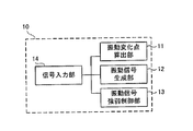
- FIG. 1 is a block diagram illustrating a configuration of a vibration signal generation device according to the present embodiment.
- FIG. 1 for convenience of explanation, only members directly related to the present invention are shown, and the other members are not shown.
- the vibration signal generation device 10 includes a vibration change point calculation unit 11, a vibration signal generation unit 12, a vibration signal strength control unit 13, and a signal input unit 14.
- the signal input unit 14 is configured to be able to accept music data stored or recorded in, for example, a flash memory, a hard disk drive, an optical disk, or the like, or audio data input via a microphone (not shown).
- the vibration change point calculation unit 11 calculates the vibration change point of the audio signal corresponding to the music data input via the signal input unit 14.
- the vibration signal generation unit 12 generates a vibration signal that is a signal including a frequency component in a vibration frequency band that is a frequency band narrower than the audible band, from an audio signal including a frequency component of the audible band.
- the vibration signal strength control unit 13 has the amplitude of the vibration signal immediately before the vibration change point in the generated vibration signal smaller than the amplitude of the vibration signal immediately after the vibration change point in the generated vibration signal. Thus, the generated vibration signal is corrected.
- the “vibration change point calculation unit 11” and the “vibration signal strength control unit 13” according to the present embodiment are examples of the “correction unit” according to the present invention.
- the “vibration signal generation unit 12” according to the present embodiment is an example of the “vibration signal generation unit” according to the present invention.
- vibration signal generation processing Next, vibration signal generation processing in the vibration signal generation device 10 configured as described above will be specifically described with reference to the flowchart of FIG. Here, it is assumed that music data is input via the signal input unit 14.
- the vibration change point calculation unit 11 calculates the change point of the audio signal (see FIG. 3A) corresponding to the music data input via the signal input unit 14 (FIG. 3B). ) (See broken line)) (step S101).
- the “change point” is calculated as a point on the time axis (that is, calculated as “time”).
- FIG. 4 is a conceptual diagram illustrating an example of a change point calculation method according to the present embodiment.
- the vibration change point calculation unit 11 performs, for example, a fast Fourier transform (FFT) on the audio signal, and the frequency at a certain time (here, time t1) as shown in FIG. And the FFT power are obtained.
- FFT fast Fourier transform
- the vibration change point calculation unit 11 calculates the sum of the increments of the FFT power related to each frequency component (for example, the difference between the FFT power at time t1 and the FFT power at time t1-1).
- the change point of the audio signal is calculated based on the rate of increase of the sum of the FFT power increases.
- the vibration change point calculation unit 11 calculates the change point of the audio signal based on the following relational expression.
- P (t1, f) means the sum of increments of the FFT power at each frequency at time t1
- N (t1) is calculated from the FFT power around P (t1, fx) at time t1. This means the calculated degree of change.
- the vibration change point calculation unit 11 extracts a part of the frequency components included in the audio signal (for example, the frequency f2 to the frequency f3; see the shaded portion in FIG. 4B), The change point may be obtained based on the sum of the increments of the FFT power related to each of the extracted frequency components.
- the vibration change point calculation unit 11 extracts vibration change points whose intervals are equal to or greater than a specific interval from the calculated plurality of change points (see the broken line in FIG. 3C).
- the vibration signal generation unit 12 In parallel with or in parallel with the processing of steps S101 and S102 described above, the vibration signal generation unit 12 generates a vibration signal composed of frequency components in a vibration frequency band such as 60 Hz to 130 Hz from the audio signal. (Step S103). Note that the amplitude of the generated vibration signal is determined according to the amplitude of the input audio signal.
- the vibration signal strength control unit 13 determines that the amplitude of the vibration signal immediately before the vibration change point in the generated vibration signal is the amplitude of the vibration signal immediately after the vibration change point in the generated vibration signal.
- the generated vibration signal is corrected by performing mask processing so as to be smaller than that (step S104).
- FIG. 5 is a conceptual diagram showing the concept of the mask processing according to the present embodiment.
- the vibration signal strength control unit 13 performs a mask process on the generated vibration signal (see FIG. 5A) using, for example, a cosine type mask as shown in FIG.
- the average amplitude of the vibration signal immediately before the vibration change point (see circle a1) as shown in FIG. 6 is made lower than the average amplitude of the vibration signal immediately after the vibration change point (see circle a2).
- vibration change point of the vibration signal is the same as the vibration change point (that is, time) calculated in the process of step S102 described above, for example, as shown in FIG.
- a vibration signal as shown in FIG. 6A is corrected as shown in FIG. 6B, for example.
- FIG. 6A is an example of a vibration signal
- FIG. 6B is an example of a vibration signal subjected to mask processing.
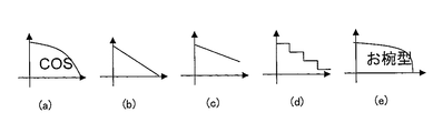
- the mask used in the mask process is not limited to the cosine mask shown in FIG. 5, but is a linear mask as shown in FIGS. 7B and 7C, for example, as shown in FIG. 7D.
- the end portion of the mask may be before the vibration change point 2 as shown in FIG. In this case, when the mask process is performed on the vibration signal as shown in FIG. 8B, the vibration signal as shown in FIG. 8C is obtained.
- FIG. 9 is a block diagram illustrating a configuration of the acoustic experience system according to the first example.
- the arrow in a figure has shown the flow of a signal (same in subsequent figures).
- the body sensation sound system 100 includes a vibration signal generation device 10 and an electromechanical vibration converter 40.
- the vibration signal generation device 10 includes the low-pass filter 12 as the vibration signal generation unit 12 described above.
- the signal input unit 14 transmits an audio signal supplied from the outside to the vibration change point calculation unit 11 and the low-pass filter 12.
- the vibration change point calculation unit 11 calculates a vibration change point of the audio signal, and transmits a signal indicating the calculated vibration change point to the vibration signal strength control unit 40.
- the vibration signal strength control unit 13 performs a predetermined mask process on the vibration signal generated by the low-pass filter 12 based on the received signal indicating the vibration change point. Then, the vibration signal strength control unit 13 transmits the vibration signal subjected to the mask processing to the electro-mechanical vibration converter 40.
- the vibration signal strength is reduced so that the mask process is not performed on the vibration signal.
- the control unit 13 may be configured.
- FIG. 10 is a block diagram illustrating a configuration of the acoustic experience system according to the second embodiment.
- the description which overlaps with 1st Example is abbreviate
- the body sensation sound system 200 includes a vibration signal generation device 10, a user interface unit 20, a memory 30, an electro-mechanical vibration converter 40, a delay circuit (Delay) 50, and an output terminal (Audio OUT) 60. Configured.
- the user interface unit 20 includes, for example, a display unit (not shown) that provides a user with a music selection screen, a mode selection screen, etc., buttons and the like (not shown) for the user to perform input operations, have.
- a display unit not shown
- buttons and the like not shown for the user to perform input operations, have.
- the “mode selection screen” names corresponding to a plurality of frequency bands (for example, “vocal tracking”, “base tracking”, “frequency band designation”) are displayed.
- the frequency band is set as a fixed value in advance by the manufacturer or the like for “vocal tracking” and “base tracking” (so-called preset values).
- the “frequency band designation” allows the user to freely set the frequency band.
- a signal indicating the selected piece of music data is transmitted to the memory 30. Then, one piece of music data is transmitted from the memory 30 to the signal input unit 14 of the vibration signal generation device 10.
- the frequency band corresponding to the selected name (hereinafter referred to as “vibration conversion” as appropriate).
- a signal indicating the band “) is transmitted to the vibration change point calculation unit 11 of the vibration signal generation device 10.
- the signal input unit 14 transmits one piece of music data to the vibration change point calculation unit 11.
- the signal input unit 14 further transmits one piece of music data to the output terminal 60 via the delay circuit 50.
- the vibration change point calculation unit 11 that has received one piece of music data calculates a vibration change point based on the received one piece of music data and a signal indicating a vibration change band. That is, the vibration change point calculation unit 11 extracts a frequency component within the vibration change band from the frequency components included in one piece of music data, and changes the vibration based on the FFT power and the like related to the extracted frequency component. Calculate points.
- the vibration change point calculation unit 11 transmits one piece of music data and a signal indicating the calculated vibration change point to the vibration signal generation unit 12.
- the vibration signal generator 12 generates a vibration signal from the received piece of music data.
- the vibration signal generation unit 12 transmits a generated vibration signal and a signal indicating a vibration change point to the vibration signal strength control unit 13.
- the vibration signal strength control unit 13 performs a predetermined mask process on the vibration signal based on the signal indicating the vibration change point. Then, the vibration signal strength control unit 13 transmits the vibration signal subjected to the mask processing to the electro-mechanical vibration converter 40.
- one piece of music data output from the output terminal 60 is delayed by a period caused by the delay circuit 50, the reproduction position of one piece of music data and the vibration generated by the electromechanical vibration converter 40 are used. And can be synchronized.
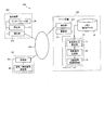
- FIG. 11 is a block diagram illustrating a configuration of the acoustic experience system according to the third example.
- the description which overlaps with 1st Example is abbreviate
- the body sensation sound system 300 includes a terminal device 301, a server device 302, and a vibration unit 303 that are connected to each other via a network 304.
- the interface unit 20 of the terminal device 301 acquires music information indicating a list of one or more music data stored in the memory 30 of the server device 302 via the communication unit 312, the network 304, and the communication unit 322.
- the interface unit 20 displays the acquired music information to the user.
- the interface unit 20 When the interface unit 20 receives an input indicating one piece of music data among the pieces of music data indicated by the piece of music information, the interface unit 20 sends a music specifying signal for specifying one piece of music data to the server unit 302, The data is transmitted via the network 304 and the communication unit 322.
- the control unit 321 of the server device 302 transmits one piece of music data specified by the received music specifying signal to the playback unit 311 of the terminal device 301 via the communication unit 322, the network 304, and the communication unit 312. To do.
- the control unit 321 further transmits one piece of music data to the vibration signal generation device 10.
- the control unit 321 sends the vibration signal subjected to the mask processing output from the vibration signal generation device 10 to the electro-mechanical vibration conversion unit 40 of the vibration unit 303 through the communication unit 322, the network 304, and the communication unit 331. Send through.
- the “interface unit 20” according to the present embodiment is an example of “accepting means” and “display means” according to the present invention.
- “Memory 30”, “communication unit 312”, and “communication unit 322” according to the present embodiment are examples of “storage unit”, “first communication unit”, and “second communication unit” according to the present invention, respectively. is there.
- SYMBOLS 10 Vibration signal generator, 11 ... Vibration change point calculation part, 12 ... Vibration signal generation part, 13 ... Vibration signal strength control part, 14 ... Signal input part, 20 ... User interface part, 40 ... Electro-mechanical vibration converter , 100, 200, 300 ... sensory acoustic system
Landscapes
- Physics & Mathematics (AREA)
- Engineering & Computer Science (AREA)
- Acoustics & Sound (AREA)
- Signal Processing (AREA)
- User Interface Of Digital Computer (AREA)
- Details Of Audible-Bandwidth Transducers (AREA)
Abstract
振動信号生成装置(10)は、可聴帯域内の周波数成分を含んでなる音響信号から、前記可聴帯域よりも狭い周波数帯域である振動周波数帯域内の周波数成分からなる信号である振動信号を生成する振動信号生成手段(12)と、(i)前記音響信号の振動変化点を算出し、(ii)前記生成された振動信号のうち、前記振動変化点の直前の振動信号の振幅が、前記生成された振動信号のうち、前記振動変化点の直後の振動信号の振幅よりも小さくなるように、前記生成された振動信号を補正する補正手段(11、13)と、を備える。
Description
本発明は、例えば体感音響装置等に採用される電気-機械振動変換器に供給される比較的低い周波数を有する振動信号を生成する振動信号生成装置及び方法、コンピュータプログラム、並びに体感音響システムの技術分野に関する。
この種の装置として、例えば、電気信号を機械的振動に変換するトランスデューサを駆動するために入力された音楽信号を、モード切替スイッチの切り替えに応じてイコライズ(こおでは、カットオフ周波数及び増幅度の切替)する装置が提案されている(特許文献1参照)。
尚、特許文献2には、周波数成分を有する入力信号の周期毎の立ち上がり部を基に、出力信号の立ち上がり部を生成すると共に、該生成された出力信号の立ち上がり部のピークレベルからレベルを次第に減衰させて出力信号の減衰部を生成するエフェクタが記載されている。
しかしながら、特許文献1に記載の技術では、十分にメリハリのある体感振動をユーザに提供することが困難になる可能性があるという技術的問題点がある。
本発明は、例えば上記問題点に鑑みてなされたものであり、メリハリのある体感振動をユーザに提供することができる振動信号生成装置及び方法、コンピュータプログラム、並びに体感音響システムを提供することを課題とする。
本発明の振動信号生成装置は、上記課題を解決するために、可聴帯域内の周波数成分を含んでなる音響信号から、前記可聴帯域よりも狭い周波数帯域である振動周波数帯域内の周波数成分からなる信号である振動信号を生成する振動信号生成手段と、(i)前記音響信号の時間変動が所定条件を満たす時間軸上の点である振動変化点を算出し、(ii)前記生成された振動信号のうち、前記振動変化点の直前の振動信号の振幅が、前記生成された振動信号のうち、前記振動変化点の直後の振動信号の振幅よりも小さくなるように、前記生成された振動信号を補正する補正手段と、を備える。
本発明の振動信号生成装置によれば、振動信号生成手段は、可聴帯域(即ち、20Hz(ヘルツ)~20000Hz)内の周波数成分を含んでなる音響信号から、該可聴帯域よりも狭い周波数帯域である振動周波数帯域内の周波数成分からなる信号である振動信号を生成する。尚、振動信号の生成方法については、公知の各種態様を適用可能であるので、ここではその詳細についての説明は省略する。
ここで、「振動周波数帯域」は、典型的には、電気-機械振動変換器により適切に機械振動に変換可能な周波数帯域(例えば60Hz~130Hz等)として設定される。このような「振動周波数帯域」は、対象とする電気-機械振動変換器の性能に応じて適宜設定すればよい。
例えばメモリ、プロセッサ等を備えてなる補正手段は、(i)音響信号の振動変化点を算出し、(ii)生成された振動信号のうち、振動変化点の直前の振動信号の振幅が、生成された振動信号のうち、該振動変化点の直後の振動信号の振幅よりも小さくなるように、生成された振動信号を補正する。
「所定条件」は、(i)音響信号の周波数成分の振幅の変化量が所定値より大きいこと、及び(ii)振動周波数帯域の最低周波数に応じて定められる期間(例えば、最低周波数が50Hzである場合は、0.02秒)以上相互に離れていること(つまり、直前の振動変化点から一定期間経過していること)、である。
従って、「振動変化点」とは、音響信号の周波数成分の振幅の変化量が所定値より大きく、且つ、振動周波数帯域の最低周波数に応じて定められる期間以上相互に離れている時間軸上の点を意味する。
ここで、「音響信号の周波数成分の振幅の変化量が所定値より大きい点」は、音響信号における所謂「発音位置」に相当する点である。従って、「振動変化点」は、発音位置のうち、「振動周波数帯域の最低周波数に応じて定められる期間以上相互に離れている」発音位置と、言い換えることができる。尚、「発音位置」とは、複数の音が時間軸上で連続することにより構成される楽曲において、一の音が、該一の音を発する楽器により発せられたタイミングを言う。
このような「振動変化点」は、例えば次のように求めればよい。即ち、(i)先ず、音響信号に対して高速フーリエ変換を施し、一の時刻において音響信号を構成する周波数成分各々のパワーの増加分の和を求め、一の時刻とは異なる他の時刻からの変化率が所定値より大きいことを条件に、振動変化点の候補とする。(ii)次に、複数の振動変化点の候補のうち、互いに、振動周波数帯域の最低周波数に応じて定められる期間以上離れている点を、振動変化点として決定する。
本願発明者の研究によれば、以下の事項が判明している。即ち、従来は、電気-機械振動変換器に音響信号がそのまま供給されることが多い。すると、供給された音響信号の全てに対して増幅等の処理が施されるため、音響信号によっては、ユーザが体感する振動が抑揚の少ない又はないものとなるおそれがある。例えばローパスフィルタ等を用いて、音響信号のうち比較的低い周波数成分のみを抽出して、電気-機械振動変換器に供給する装置も提案されているが、メリハリのある体感振動という点では十分とはいえない。
しかるに本発明では、補正手段により、上述の如く、(i)音響信号の振動変化点が算出され、(ii)生成された振動信号のうち、振動変化点の直前の振動信号の振幅が、生成された振動信号のうち、該振動変化点の直後の振動信号の振幅よりも小さくなるように、生成された振動信号が補正される。このため、振動変化点の前後では、比較的大きな振動の変化、即ち、メリハリのある体感振動をユーザに提供することができる。
本発明の振動信号生成装置の一態様では、前記補正手段は、前記振動変化点の直前の振動信号の振幅を減衰させることによって、前記振動変化点の直前の振動信号の振幅が、前記振動変化点の直後の振動信号の振幅よりも小さくなるように、前記生成された振動信号を補正する。
この態様によれば、比較的容易にして、メリハリのある体感振動をユーザに提供することができ、実用上非常に有利である。
本発明の振動信号生成装置の他の態様では、前記補正手段は、前記振動変化点の直後の振動信号の振幅を増幅させることによって、前記振動変化点の直前の振動信号の振幅が、前記振動変化点の直後の振動信号の振幅よりも小さくなるように、前記生成された振動信号を補正する。
この態様によれば、比較的容易にして、メリハリのある体感振動をユーザに提供することができ、実用上非常に有利である。
本発明の振動信号生成方法は、上記課題を解決するために、可聴帯域内の周波数成分を含んでなる音響信号から、前記可聴帯域よりも狭い周波数帯域である振動周波数帯域内の周波数成分からなる信号である振動信号を生成する振動信号生成工程と、(i)前記音響信号の時間変動が所定条件を満たす時間軸上の点である振動変化点を算出し、(ii)前記生成された振動信号のうち、前記振動変化点の直前の振動信号の振幅が、前記生成された振動信号のうち、前記振動変化点の直後の振動信号の振幅よりも小さくなるように、前記生成された振動信号を補正する補正工程と、を備える。
本発明の振動信号生成方法によれば、上述した本発明の振動信号生成装置と同様に、メリハリのある体感振動をユーザに提供することができる。尚、本発明の振動信号生成方法においても、上述した本発明の振動信号生成装置の各種態様と同様の各種態様を採ることができる。
本発明のコンピュータプログラムは、上記課題を解決するために、コンピュータを、可聴帯域内の周波数成分を含んでなる音響信号から、前記可聴帯域よりも狭い周波数帯域である振動周波数帯域内の周波数成分からなる信号である振動信号を生成する振動信号生成手段と、(i)前記音響信号の時間変動が所定条件を満たす時間軸上の点である振動変化点を算出し、(ii)前記音響信号のうち、前記振動変化点の直前の振動信号の振幅が、前記生成された振動信号のうち、前記振動変化点の直後の振動信号の振幅よりも小さくなるように、前記生成された振動信号を補正する補正手段と、として機能させる。
本発明のコンピュータプログラムによれば、当該コンピュータプログラムを、振動信号生成装置に備えられたコンピュータに、通信手段を介してダウンロードさせた後に実行させれば、上述した本発明の振動信号生成装置を比較的容易にして実現することができる。これにより、上述した本発明の振動信号生成装置の場合と同様に、メリハリのある体感振動をユーザに提供することができる。尚、本発明のコンピュータプログラムにおいても、上述した本発明の振動信号生成装置の各種態様と同様の各種態様を採ることができる。
本発明の記録媒体は、上記課題を解決するために、本発明のコンピュータプログラムを格納する。
本発明の記録媒体によれば、例えばCD-ROM(Compact Disc Read Only Memory)、DVD-ROM(DVD Read Only Memory)等である当該記録媒体から、上述した本発明のコンピュータプログラムを、振動信号生成装置に備えられたコンピュータに読み込んで実行させれば、上述した本発明の振動信号生成装置を比較的容易にして実現することができる。これにより、上述した本発明の振動信号生成装置の場合と同様に、メリハリのある体感振動をユーザに提供することができる。
本発明の体感振動システムは、上記課題を解決するために、ネットワークを介して相互に接続された端末装置、サーバ装置及び電気-機械振動変換装置を備えてなる体感音響システムであって、前記サーバ装置は、複数の楽曲データ、及び前記複数の楽曲データの一覧を示す楽曲情報を格納する格納手段を有し、前記端末装置は、ユーザの入力を受付可能な受付手段と、前記ネットワークを介して前記楽曲情報を取得して、前記ユーザに対して表示する表示手段と、前記受付手段により受け付けられた前記ユーザの入力に応じて、前記楽曲情報により示される複数の楽曲データのうち一の楽曲データを特定する信号である楽曲特定信号を、前記ネットワークを介して、前記サーバ装置に送信する第1通信手段と、
を有し、前記サーバ装置は、前記楽曲特定信号により特定される一の楽曲データに対応し、可聴帯域内の周波数成分を含んでなる音響信号から、前記可聴帯域よりも狭い周波数帯域である振動周波数帯域内の周波数成分からなる信号である振動信号を生成する振動信号生成手段と、(i)前記音響信号の時間変動が所定条件を満たす時間軸上の点である振動変化点を算出し、(ii)前記生成された振動信号のうち、前記振動変化点の直前の振動信号の振幅が、前記生成された振動信号のうち、前記振動変化点の直後の振動信号の振幅よりも小さくなるように、前記生成された振動信号を補正する補正手段と、前記補正された振動信号を、前記ネットワークを介して、前記電気-機械振動変換装置に送信する第2通信手段と、を更に有する。
を有し、前記サーバ装置は、前記楽曲特定信号により特定される一の楽曲データに対応し、可聴帯域内の周波数成分を含んでなる音響信号から、前記可聴帯域よりも狭い周波数帯域である振動周波数帯域内の周波数成分からなる信号である振動信号を生成する振動信号生成手段と、(i)前記音響信号の時間変動が所定条件を満たす時間軸上の点である振動変化点を算出し、(ii)前記生成された振動信号のうち、前記振動変化点の直前の振動信号の振幅が、前記生成された振動信号のうち、前記振動変化点の直後の振動信号の振幅よりも小さくなるように、前記生成された振動信号を補正する補正手段と、前記補正された振動信号を、前記ネットワークを介して、前記電気-機械振動変換装置に送信する第2通信手段と、を更に有する。
本発明の体感音響システムによれば、端末装置、サーバ装置及び電気-機械振動変換器は、例えばインターネット、LAN(Local Area Network)等のネットワークを介して相互に接続されている。端末装置は、受付手段及び第1通信手段を備えて構成されている。サーバ装置は、格納手段、振動信号生成手段、補正手段及び第2通信手段を備えて構成されている。
本発明の体感音響システムよれば、上述した本発明の振動信号生成装置と同様に、メリハリのある体感振動をユーザに提供することができる。
本発明の作用及び他の利得は次に説明する実施するための形態から明らかにされる。
以下、本発明に係る振動信号生成装置の実施形態を、図面に基づいて説明する。
(振動信号生成装置の構成)
本実施形態に係る振動信号生成装置の構成を、図1を参照して説明する。図1は、本実施形態に係る振動信号生成装置の構成を示すブロック図である。尚、図1では、説明の便宜上、本発明と直接関連のある部材のみを示し、その他の部材については図示を省略している。
本実施形態に係る振動信号生成装置の構成を、図1を参照して説明する。図1は、本実施形態に係る振動信号生成装置の構成を示すブロック図である。尚、図1では、説明の便宜上、本発明と直接関連のある部材のみを示し、その他の部材については図示を省略している。
図1において、振動信号生成装置10は、振動変化点算出部11、振動信号生成部12、振動信号強弱制御部13及び信号入力部14を備えて構成されている。
信号入力部14は、例えばフラッシュメモリ、ハードディスクドライブ、光ディスク等に格納又は記録された楽曲データ、或いはマイク(図示せず)を介して入力された音声データを受付可能に構成されている。
振動変化点算出部11は、信号入力部14を介して入力された楽曲データ等に対応するオーディオ信号の振動変化点を算出する。
振動信号生成部12は、可聴帯域の周波数成分を含んでなるオーディオ信号から、該可聴帯域よりも狭い周波数帯域である振動周波数帯域内の周波数成分からなる信号である振動信号を生成する。
振動信号強弱制御部13は、生成された振動信号のうち、振動変化点の直前の振動信号の振幅が、生成された振動信号のうち、該振動変化点の直後の振動信号の振幅よりも小さくなるように、生成された振動信号を補正する。
本実施形態に係る「振動変化点算出部11」及び「振動信号強弱制御部13」は、本発明に係る「補正手段」の一例である。本実施形態に係る「振動信号生成部12」は、本発明に係る「振動信号生成手段」の一例である。
(振動信号生成処理)
次に、上述の如く構成された振動信号生成装置10における振動信号生成処理について、図2のフローチャートを参照して具体的に説明する。ここでは、信号入力部14を介して楽曲データが入力されるものとする。
次に、上述の如く構成された振動信号生成装置10における振動信号生成処理について、図2のフローチャートを参照して具体的に説明する。ここでは、信号入力部14を介して楽曲データが入力されるものとする。
図2において、先ず、振動変化点算出部11は、信号入力部14を介して入力された楽曲データに対応するオーディオ信号(図3(a)参照)の変化点を算出する(図3(b)中の破線参照)(ステップS101)。尚、「変化点」は、時間軸上の点として算出される(即ち、“時刻”として算出される)。
ここで、オーディオ信号の変化点の算出方法について、図4を参照して説明を加える。図4は、本実施形態に係る変化点算出方法の一例を示す概念図である。
振動変化点算出部11は、先ず、オーディオ信号に対して、例えば高速フーリエ変換(Fst Fourier Transform:FFT)を施し、図4(a)に示すようなある時刻(ここでは、時刻t1)における周波数とFFTパワーとの関係を求める。
次に、振動変化点算出部11は、周波数成分各々に係るFFTパワーの増加分(例えば、時刻t1のFFTパワーと、時刻t1-1のFFTパワーの差分)の和を求め、例えば該求められたFFTパワーの増加分の和の増加率に基づいて、オーディオ信号の変化点を算出する。
具体的には例えば、振動変化点算出部11は、次の関係式に基づいてオーディオ信号の変化点を算出する。
P(t1,f)/P(t1-1,f)>N(t1)
ここで、P(t1,f)は、時刻t1における周波数各々のFFTパワーの増加分の和を意味し、N(t1)は、時刻t1において、P(t1,fx)の周囲のFFTパワーから算出される変化度合いを意味する。
P(t1,f)/P(t1-1,f)>N(t1)
ここで、P(t1,f)は、時刻t1における周波数各々のFFTパワーの増加分の和を意味し、N(t1)は、時刻t1において、P(t1,fx)の周囲のFFTパワーから算出される変化度合いを意味する。
尚、振動変化点算出部11は、オーディオ信号に含まれる周波数成分のうち一部の周波数成分(例えば、周波数f2~周波数f3;図4(b)中の網掛け部分参照)を抽出して、該抽出された周波数成分各々に係るFFTパワーの増加分の和に基づいて変化点を求めてもよい。
再び図2に戻り、振動変化点算出部11は、算出された複数の変化点から、互いの間隔が特定間隔以上となるような振動変化点を抽出する(図3(c)中の破線参照)(ステップS102)。ここで、「特定間隔」は、例えば、後述する振動周波数帯域の下限値に応じて設定されている。具体的には例えば、振動周波数帯域の下限値が50Hzである場合、特定間隔は、0.02秒(=1秒÷50Hz)等と設定される。
上述したステップS101及びS102の処理と並列して、又は相前後して、振動信号生成部12は、オーディオ信号から、例えば60Hz~130Hz等である振動周波数帯域内の周波数成分からなる振動信号を生成する(ステップS103)。尚、生成される振動信号の振幅は、入力されたオーディオ信号の振幅に応じて決定される。
次に、振動信号強弱制御部13は、生成された振動信号のうち、振動変化点の直前の振動信号の振幅が、生成された振動信号のうち、該振動変化点の直後の振動信号の振幅よりも小さくなるようなマスク処理施すことによって、生成された振動信号を補正する(ステップS104)。
ここで、マスク処理について、図5を参照して説明する。図5は、本実施形態に係るマスク処理の概念を示す概念図である。
振動信号強弱制御部13は、生成された振動信号(図5(a)参照)に、例えば図5中に示すようなコサイン型のマスク等を用いたマスク処理を施して、図5(b)に示すような、振動変化点の直前の振動信号の平均振幅(円a1参照)を、該振動変化点の直後の振動信号の平均振幅(円a2参照)よりも低くする。
尚、振動信号の振動変化点は、例えば図3(d)に示すように、上述のステップS102の処理において算出された振動変化点(即ち、時刻)と同一である。
上述のステップS104の処理により、例えば図6(a)に示すような振動信号は、例えば図6(b)に示すように補正される。図6(a)は、振動信号の一例であり、図6(b)は、マスク処理が施された振動信号の一例である。
尚、マスク処理で用いられるマスクは、図5に示したコサイン型のマスクに限らず、例えば図7(b)及び(c)に示すような直線型のマスク、図7(d)に示すような階段型のマスク、又は図7(e)に示すようなお椀型のマスク等であってもよい。
また、マスクの終端部は、図8(a)に示すように、振動変化点2よりも前であってもよい。この場合、図8(b)に示すような振動信号に対してマスク処理が施されると、図8(c)に示すような振動信号が得られる。
以下、本発明に係る振動信号生成装置を体感音響システムに適用した場合の実施例について、図面に基づいて説明する。
<第1実施例>
第1実施例に係る体感音響システムについて、図9を参照して説明する。図9は、第1実施例に係る音響体感システムの構成を示すブロック図である。尚、図中の矢印は、信号の流れを示している(以降の図において同じ)。
第1実施例に係る体感音響システムについて、図9を参照して説明する。図9は、第1実施例に係る音響体感システムの構成を示すブロック図である。尚、図中の矢印は、信号の流れを示している(以降の図において同じ)。
図9において、体感音響システム100は、振動信号生成装置10と電気-機械振動変換器40とを備えて構成されている。尚、本実施例では、振動信号生成装置10は、上述した振動信号生成部12としてのローパスフィルタ12を有している。
信号入力部14は、振動変化点算出部11及びローパスフィルタ12に対して、外部から供給されたオーディオ信号を送信する。振動変化点算出部11は、オーディオ信号の振動変化点を算出し、該算出された振動変化点を示す信号を、振動信号強弱制御部40に送信する。
振動信号強弱制御部13は、受信された振動変化点を示す信号に基づいて、ローパスフィルタ12により生成された振動信号に対して所定のマスク処理を施す。そして、振動信号強弱制御部13は、電気-機械振動変換器40に対して、該マスク処理が施された振動信号を送信する。
尚、例えば振動変化点算出部11における周波数解析の際に、倍音成分が比較的多く含まれていることを検出した場合には、振動信号に対してマスク処理を施さないように、振動信号強弱制御部13を構成してもよい。
<第2実施例>
第2実施例に係る体感音響システムについて、図10を参照して説明する。図10は、第2実施例に係る音響体感システムの構成を示すブロック図である。尚、第1実施例と重複する説明を省略すると共に、図面上における共通箇所には同一符号を付して示し、基本的に異なる点についてのみ説明する。
第2実施例に係る体感音響システムについて、図10を参照して説明する。図10は、第2実施例に係る音響体感システムの構成を示すブロック図である。尚、第1実施例と重複する説明を省略すると共に、図面上における共通箇所には同一符号を付して示し、基本的に異なる点についてのみ説明する。
図10において、において、体感音響システム200は、振動信号生成装置10、ユーザインターフェース部20、メモリ30、電気-機械振動変換器40、遅延回路(Delay)50及び出力端子(Audio OUT)60を備えて構成されている。
ユーザインターフェース部20は、ユーザに対して、例えば楽曲選択画面、モード選択画面等を提供する表示部(図示せず)と、該ユーザが入力操作を行うためのボタン等(図示せず)と、を有している。「楽曲選択画面」には、例えばフラッシュメモリ等であるメモリ30に予め格納されている一又は複数の楽曲データの一覧が表示される。
「モード選択画面」には、複数の周波数帯域に対応する名称(ここでは例えば、“ボーカル追従”、“ベース追従”、“周波数帯指定”)が表示される。尚、「ボーカル追従」及び「ベース追従」は、製造者等により予め固定値として周波数帯域が設定されている(所謂、プリセット値)。他方、「周波数帯域指定」は、ユーザが自由に周波数帯域を設定可能である。
ユーザにより楽曲選択画面に表示された楽曲データの一覧から一の楽曲データが選択されると、メモリ30に対して、該選択された一の楽曲データを示す信号が送信される。そして、メモリ30から、振動信号生成装置10の信号入力部14に対して、一の楽曲データが送信される。
他方、ユーザによりモード選択画面に表示された複数の周波数帯域に対応する名称のうち一の名称が選択されると、該選択された一の名称に対応する周波数帯域(以降、適宜、“振動変換帯域”と称する)を示す信号が、振動信号生成装置10の振動変化点算出部11に対して送信される。
振動信号生成装置10において、信号入力部14は、振動変化点算出部11に対して、一の楽曲データを送信する。信号入力部14は、更に、出力端子60に対して、遅延回路50を介して一の楽曲データを送信する。
一の楽曲データを受信した振動変化点算出部11は、受信された一の楽曲データ及び振動変化帯域を示す信号に基づいて、振動変化点を算出する。つまり、振動変化点算出部11は、一の楽曲データに含まれる周波数成分のうち、振動変化帯域内の周波数成分を抽出して、該抽出された周波数成分に係るFFTパワー等に基づいて振動変化点を算出する。振動変化点算出部11は、振動信号生成部12に対して、一の楽曲データ、及び算出された振動変化点を示す信号を送信する。
振動信号生成部12は、受信された一の楽曲データから振動信号を生成する。振動信号生成部12は、振動信号強弱制御部13に対して、生成された振動信号及び振動変化点を示す信号を送信する。
振動信号強弱制御部13は、振動変化点を示す信号に基づいて、振動信号に対して所定のマスク処理を施す。そして、振動信号強弱制御部13は、電気-機械振動変換器40に対して、該マスク処理が施された振動信号を送信する。
ここで、出力端子60から出力される一の楽曲データは、遅延回路50に起因する期間だけ遅延されるので、一の楽曲データの再生位置と、電気-機械振動変換器40により発生される振動と、を同期させることができる。
このため、一の楽曲データに対応する楽曲との調和性を保ちつつ、メリハリのある体感振動をユーザに提供することができる。
<第3実施例>
第3実施例に係る体感音響システムについて、図11を参照して説明する。図11は、第3実施例に係る音響体感システムの構成を示すブロック図である。尚、第1実施例と重複する説明を省略すると共に、図面上における共通箇所には同一符号を付して示し、基本的に異なる点についてのみ説明する。
第3実施例に係る体感音響システムについて、図11を参照して説明する。図11は、第3実施例に係る音響体感システムの構成を示すブロック図である。尚、第1実施例と重複する説明を省略すると共に、図面上における共通箇所には同一符号を付して示し、基本的に異なる点についてのみ説明する。
図11において、体感音響システム300は、ネットワーク304を介して相互に接続された端末装置301、サーバ装置302及び振動ユニット303を備えて構成されている。
端末装置301のインターフェース部20は、通信部312、ネットワーク304及び通信部322を介して、サーバ装置302のメモリ30に格納されている一又は複数の楽曲データの一覧を示す楽曲情報を取得する。インターフェース部20は、ユーザに対して、該取得された楽曲情報を表示する。
インターフェース部20は、楽曲情報により示された楽曲データのうち一の楽曲データを示す入力を受け付けた場合、サーバ装置302に対して、一の楽曲データを特定する楽曲特定信号を、通信部312、ネットワーク304及び通信部322を介して送信する。
サーバ装置302の制御部321は、端末装置301の再生部311に対して、受信された楽曲特定信号により特定される一の楽曲データを、通信部322、ネットワーク304及び通信部312を介して送信する。制御部321は、更に、振動信号生成装置10に対して、一の楽曲データを送信する。
制御部321は、振動ユニット303の電気-機械振動変換部40に対して、振動信号生成装置10から出力されたマスク処理が施された振動信号を、通信部322、ネットワーク304及び通信部331を介して送信する。
本実施例に係る「インターフェース部20」は、本発明に係る「受付手段」及び「表示手段」の一例である。本実施例に係る「メモリ30」、「通信部312」及び「通信部322」は、夫々、本発明に係る「格納手段」、「第1通信手段」及び「第2通信手段」の一例である。
本発明は、上述した実施形態に限られるものではなく、請求の範囲及び明細書全体から読み取れる発明の要旨或いは思想に反しない範囲で適宜変更可能であり、そのような変更を伴う振動信号生成装置及び方法、コンピュータプログラム、並びに体感音響システムもまた本発明の技術的範囲に含まれるものである。
10…振動信号生成装置、11…振動変化点算出部、12…振動信号生成部、13…振動信号強弱制御部、14…信号入力部、20…ユーザインターフェース部、40…電気-機械振動変換器、100、200、300…体感音響システム
Claims (7)
- 可聴帯域内の周波数成分を含んでなる音響信号から、前記可聴帯域よりも狭い周波数帯域である振動周波数帯域内の周波数成分からなる信号である振動信号を生成する振動信号生成手段と、
(i)前記音響信号の時間変動が所定条件を満たす時間軸上の点である振動変化点を算出し、(ii)前記生成された振動信号のうち、前記振動変化点の直前の振動信号の振幅が、前記生成された振動信号のうち、前記振動変化点の直後の振動信号の振幅よりも小さくなるように、前記生成された振動信号を補正する補正手段と、
を備えることを特徴とする振動信号生成装置。 - 前記補正手段は、前記振動変化点の直前の振動信号の振幅を減衰させることによって、前記振動変化点の直前の振動信号の振幅が、前記振動変化点の直後の振動信号の振幅よりも小さくなるように、前記生成された振動信号を補正することを特徴とする請求項1に記載の振動信号生成装置。
- 前記補正手段は、前記振動変化点の直後の振動信号の振幅を増幅させることによって、前記振動変化点の直前の振動信号の振幅が、前記振動変化点の直後の振動信号の振幅よりも小さくなるように、前記生成された振動信号を補正することを特徴とする請求項1に記載の振動信号生成装置。
- 可聴帯域内の周波数成分を含んでなる音響信号から、前記可聴帯域よりも狭い周波数帯域である振動周波数帯域内の周波数成分からなる信号である振動信号を生成する振動信号生成工程と、
(i)前記音響信号の時間変動が所定条件を満たす時間軸上の点である振動変化点を算出し、(ii)前記生成された振動信号のうち、前記振動変化点の直前の振動信号の振幅が、前記生成された振動信号のうち、前記振動変化点の直後の振動信号の振幅よりも小さくなるように、前記生成された振動信号を補正する補正工程と、
を備えることを特徴とする振動信号生成方法。 - コンピュータを、
可聴帯域内の周波数成分を含んでなる音響信号から、前記可聴帯域よりも狭い周波数帯域である振動周波数帯域内の周波数成分からなる信号である振動信号を生成する振動信号生成手段と、
(i)前記音響信号の時間変動が所定条件を満たす時間軸上の点である振動変化点を算出し、(ii)前記生成された振動信号のうち、前記振動変化点の直前の振動信号の振幅が、前記生成された振動信号のうち、前記振動変化点の直後の振動信号の振幅よりも小さくなるように、前記生成された振動信号を補正する補正手段と、
として機能させることを特徴とするコンピュータプログラム。 - 請求項5に記載のコンピュータプログラムを格納することを特徴とする記録媒体。
- ネットワークを介して相互に接続された端末装置、サーバ装置及び電気-機械振動変換装置を備えてなる体感音響システムであって、
前記サーバ装置は、複数の楽曲データ、及び前記複数の楽曲データの一覧を示す楽曲情報を格納する格納手段を有し、
前記端末装置は、
ユーザの入力を受付可能な受付手段と、
前記ネットワークを介して前記楽曲情報を取得して、前記ユーザに対して表示する表示手段と、
前記受付手段により受け付けられた前記ユーザの入力に応じて、前記楽曲情報により示される複数の楽曲データのうち一の楽曲データを特定する信号である楽曲特定信号を、前記ネットワークを介して、前記サーバ装置に送信する第1通信手段と、
を有し、
前記サーバ装置は、
前記楽曲特定信号により特定される一の楽曲データに対応し、可聴帯域内の周波数成分を含んでなる音響信号から、前記可聴帯域よりも狭い周波数帯域である振動周波数帯域内の周波数成分からなる信号である振動信号を生成する振動信号生成手段と、
(i)前記音響信号の時間変動が所定条件を満たす時間軸上の点である振動変化点を算出し、(ii)前記生成された振動信号のうち、前記振動変化点の直前の振動信号の振幅が、前記生成された振動信号のうち、前記振動変化点の直後の振動信号の振幅よりも小さくなるように、前記生成された振動信号を補正する補正手段と、
前記補正された振動信号を、前記ネットワークを介して、前記電気-機械振動変換装置に送信する第2通信手段と、
を更に有する
ことを特徴とする体感音響システム。
Priority Applications (1)
| Application Number | Priority Date | Filing Date | Title |
|---|---|---|---|
| PCT/JP2011/055942 WO2012124044A1 (ja) | 2011-03-14 | 2011-03-14 | 振動信号生成装置及び方法、コンピュータプログラム、並びに体感音響システム |
Applications Claiming Priority (1)
| Application Number | Priority Date | Filing Date | Title |
|---|---|---|---|
| PCT/JP2011/055942 WO2012124044A1 (ja) | 2011-03-14 | 2011-03-14 | 振動信号生成装置及び方法、コンピュータプログラム、並びに体感音響システム |
Publications (1)
| Publication Number | Publication Date |
|---|---|
| WO2012124044A1 true WO2012124044A1 (ja) | 2012-09-20 |
Family
ID=46830178
Family Applications (1)
| Application Number | Title | Priority Date | Filing Date |
|---|---|---|---|
| PCT/JP2011/055942 Ceased WO2012124044A1 (ja) | 2011-03-14 | 2011-03-14 | 振動信号生成装置及び方法、コンピュータプログラム、並びに体感音響システム |
Country Status (1)
| Country | Link |
|---|---|
| WO (1) | WO2012124044A1 (ja) |
Citations (2)
| Publication number | Priority date | Publication date | Assignee | Title |
|---|---|---|---|---|
| JP2002064895A (ja) * | 2000-08-22 | 2002-02-28 | Nippon Telegr & Teleph Corp <Ntt> | 信号処理方法、装置及びプログラム記録媒体 |
| JP2009094561A (ja) * | 2007-10-03 | 2009-04-30 | Panasonic Corp | 音響再生装置、音響再生システム、および音響再生方法 |
-
2011
- 2011-03-14 WO PCT/JP2011/055942 patent/WO2012124044A1/ja not_active Ceased
Patent Citations (2)
| Publication number | Priority date | Publication date | Assignee | Title |
|---|---|---|---|---|
| JP2002064895A (ja) * | 2000-08-22 | 2002-02-28 | Nippon Telegr & Teleph Corp <Ntt> | 信号処理方法、装置及びプログラム記録媒体 |
| JP2009094561A (ja) * | 2007-10-03 | 2009-04-30 | Panasonic Corp | 音響再生装置、音響再生システム、および音響再生方法 |
Similar Documents
| Publication | Publication Date | Title |
|---|---|---|
| JP6416460B2 (ja) | 複数のアクチュエータを用いた音からハプティック効果への変換システム | |
| US9014397B2 (en) | Signal processing device and signal processing method | |
| JP5488128B2 (ja) | 信号処理装置 | |
| JP5811993B2 (ja) | ヘッドホン、ヘッドホンのノイズ低減方法、ノイズ低減処理用プログラム | |
| US20170245054A1 (en) | Sensor on Moving Component of Transducer | |
| KR101292772B1 (ko) | 음원 재생 장치에서 음향 특성을 계측하여 향상시키는방법, 이에 적합한 기록 매체 그리고 이에 적합한 장치 | |
| TW201834468A (zh) | 具有電壓轉偏移的轉換的揚聲器調適 | |
| KR101152781B1 (ko) | 스피커 공진 감쇄 방법 및 장치 | |
| US10708690B2 (en) | Method of an audio signal correction | |
| WO2012124044A1 (ja) | 振動信号生成装置及び方法、コンピュータプログラム、並びに体感音響システム | |
| JP6597062B2 (ja) | 雑音低減装置、雑音低減方法、雑音低減プログラム | |
| JP5880753B2 (ja) | ヘッドホン、ヘッドホンのノイズ低減方法、ノイズ低減処理用プログラム | |
| CN113994421B (zh) | 信号处理装置、弦乐器、信号处理方法及程序 | |
| JP5714774B2 (ja) | 振動信号生成装置及び方法、コンピュータプログラム、記録媒体並びに体感音響システム | |
| WO2013150649A1 (ja) | 振動信号生成装置及び方法、コンピュータプログラム、記録媒体並びに体感音響システム | |
| JP5556673B2 (ja) | 音声信号補正装置、音声信号補正方法及びプログラム | |
| WO2012124043A1 (ja) | 振動信号生成装置及び方法、コンピュータプログラム、並びに体感音響システム | |
| JP2011211547A (ja) | 収音装置および収音システム | |
| JP2014126593A (ja) | 支援システム | |
| CA3240234C (en) | System and method for monitoring audio signals | |
| JP4950119B2 (ja) | 音響処理装置及び音響処理方法 | |
| JP5707892B2 (ja) | 電子機器及び通信システム | |
| JP6538002B2 (ja) | 目的音集音装置、目的音集音方法、プログラム、記録媒体 | |
| WO2025134217A1 (ja) | 信号処理装置、信号処理方法、および非一過性記録媒体 | |
| JP2021118365A (ja) | 音再生記録装置、及びプログラム |
Legal Events
| Date | Code | Title | Description |
|---|---|---|---|
| 121 | Ep: the epo has been informed by wipo that ep was designated in this application |
Ref document number: 11861107 Country of ref document: EP Kind code of ref document: A1 |
|
| NENP | Non-entry into the national phase |
Ref country code: DE |
|
| 122 | Ep: pct application non-entry in european phase |
Ref document number: 11861107 Country of ref document: EP Kind code of ref document: A1 |
|
| NENP | Non-entry into the national phase |
Ref country code: JP |