WO2012124024A1 - ファスナーエレメント及びスライドファスナー - Google Patents
ファスナーエレメント及びスライドファスナー Download PDFInfo
- Publication number
- WO2012124024A1 WO2012124024A1 PCT/JP2011/055805 JP2011055805W WO2012124024A1 WO 2012124024 A1 WO2012124024 A1 WO 2012124024A1 JP 2011055805 W JP2011055805 W JP 2011055805W WO 2012124024 A1 WO2012124024 A1 WO 2012124024A1
- Authority
- WO
- WIPO (PCT)
- Prior art keywords
- fastener element
- fastener
- inclined surfaces
- recess
- edge
- Prior art date
- Legal status (The legal status is an assumption and is not a legal conclusion. Google has not performed a legal analysis and makes no representation as to the accuracy of the status listed.)
- Ceased
Links
Images






Classifications
-
- A—HUMAN NECESSITIES
- A44—HABERDASHERY; JEWELLERY
- A44B—BUTTONS, PINS, BUCKLES, SLIDE FASTENERS, OR THE LIKE
- A44B19/00—Slide fasteners
- A44B19/02—Slide fasteners with a series of separate interlocking members secured to each stringer tape
- A44B19/04—Stringers arranged edge-to-edge when fastened, e.g. abutting stringers
- A44B19/06—Stringers arranged edge-to-edge when fastened, e.g. abutting stringers with substantially rectangular members having interlocking projections and pieces
Definitions
- the present invention relates to a fastener element and a slide fastener, and more particularly to a fastener element having a decorative property on the surface of the fastener element and a slide fastener using the same.
- a slide fastener has a slider inserted in a row of left and right fastener elements attached to opposite tape side edges of a pair of left and right fastener tapes, and by sliding the slider along the row of fastener elements, Engage or separate.
- it has been practiced to arrange decorative parts on the surface of a fastener element or the like to give a decorative property and improve the aesthetic appearance.
- International Publication No. 98/00040 describes that a groove is provided on the surface of the fastener element and a decorative stone is fitted into the groove.
- WO 98/00040 protrudes decorative surface of the fastener element surface, there is a case where at the time of sliding of the slider, the decorative surface is scratched due to friction with the slider inner wall. Further, since the decorative surface on the surface of the fastener element protrudes, it is necessary to form the slider according to the thickness of the decorative surface of the element, so that it takes time and effort to prepare a dedicated slider. Furthermore, since the shape of the fastener element described in WO 98/00040 have a special curved shape, it takes the nail when the locking hook and the locking pawl of the slider element hardly slider sliding of There is a case where the slider is moved without permission after the movement stop state is released.
- the present invention can prevent damage to the decorative surface of the fastener element by the friction between the fastener element and the slider, the sliding stop state of the slider can be held stably, aesthetics even with fastener elements and which can be improved slide fastener I will provide a.
- the present invention in one aspect, is a fastener element that is attached to a side edge of a fastener tape, and includes an edge and a recess disposed on one or both sides of the front and back direction of the fastener tape,
- the edge portion has the maximum thickness in the front and back direction on the outer periphery of the fastener element
- the recess portion has at least two inclined surfaces that are inclined downward from the edge portion toward the inside, and the recess portion is viewed from above.
- the area ratio of the total area of the inclined surfaces to the total area of the recesses when viewed is 10% or more.
- the concave portion includes an inclined surface and a valley line between the inclined surfaces.
- the fastener element according to the present invention further includes a bottom surface in contact with the at least two inclined surfaces.
- At least two or more inclined surfaces include inclined surfaces facing each other, and the inclined surfaces facing each other have the same shape.
- the inclined surface is a flat surface.
- the fastener element according to the present invention has an inclination angle of 45 ° or less.
- the inclination angle of the inclined surface is 3 ° to 15 °.
- the inclined surface is a curved surface.
- a glossy thin film is disposed on the inclined surface.
- the thin film includes a composite coating of a metal film and a resin film.
- the thickness of the thin film is 1 ⁇ m to 30 ⁇ m.
- the thin film is formed by thermal transfer.
- the maximum depth of the recess viewed from the edge is 1 mm or less.
- the maximum depth of the recess viewed from the edge is 0.3 mm or less.
- a slide fastener having the fastener element in a part or all of a fastener element row.
- a fastener element that can prevent the decorative surface of the fastener element from being damaged due to friction between the fastener element and the slider, can maintain the sliding stop state of the slider, and can improve the appearance, and a slide fastener using the fastener element. Can be provided.
- FIG. 1 is a schematic view showing an example of a slide fastener according to an embodiment of the present invention.
- FIG. 2 is a perspective view showing an example of a fastener element according to the embodiment of the present invention.
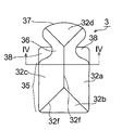
- FIG. 3 is a plan view showing an example of a fastener element according to the embodiment of the present invention.
- 4 is a cross-sectional view of the fastener element of FIG. 3 as seen from the line along the IV-IV plane.
- FIG. 5 is a cross-sectional view for explaining the inclination angle of the inclined surface of the fastener element according to the embodiment of the present invention.
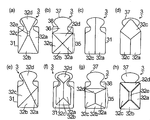
- 6 (a) to 6 (h) are plan views showing examples of the shape of the fastener element according to the embodiment of the present invention.
- FIG. 1 is a schematic view showing an example of a slide fastener according to an embodiment of the present invention.
- FIG. 2 is a perspective view showing an example of a fastener element according to the embodiment of the present invention.
- FIG. 3
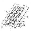
- FIG. 7 is a perspective view showing a modified example of the fastener element according to the embodiment of the present invention.
- FIG. 8 is a plan view showing the relationship between the area ratio (A / S) of the total area S of the recesses and the total area A of the inclined surfaces when the fastener element according to the embodiment of the present invention is viewed from above.
- FIG. 9 is a plan view showing the relationship between the area ratio (A / S) of the total area S of the recesses and the total area A of the inclined surfaces when the fastener element according to the modification of the embodiment of the present invention is viewed from above. is there.
- FIG. 10 shows an example of the slider according to the embodiment of the present invention, and is a cross-sectional view taken along the line XX in FIG.
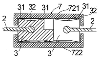
- FIG. 11 shows an example of a slider according to the embodiment of the present invention, and is a cross-sectional view taken along the line XI-XI in FIG.
- a slide fastener 1 includes a pair of fastener tapes 2, a column of fastener elements 3 arranged along the tape side edge portion 21 facing the fastener tape 2 , A slider 7 for engaging and separating the fastener elements 3, a stopper 4 disposed across one pair of fastener tapes 2 at one end of the row of fastener elements 3, and a pair disposed at the other end of the row of fastener elements 3.
- the fastener 6 is provided.
- one end of the rows of fastener elements 3 means the end on the side toward the direction in which the slider 7 is slid in the longitudinal direction of the fastener tape 2 to open the slide fastener 1.
- the other end of the row of fastener elements 3 means an end portion on the side facing the direction of closing the slide fastener 1 by sliding the slider 7 in the longitudinal direction of the fastener tape 2.
- the front and back direction of the fastener tape 2 is defined as “vertical direction” or “height (depth) direction”.
- the fastener tape 2 is made of a band-shaped material woven or knitted with synthetic fibers or natural fibers, and the winding core 5 is disposed along the tape side edge portion 21 extending in the longitudinal direction.
- the fastener element 3 has a substantially symmetrical shape with respect to the front and back surfaces of the fastener tape 2 with the fastener tape 2 as the center. There is no restriction
- FIG. 2 is a perspective view showing an example of the fastener element 3 according to the embodiment.
- Fastener element 3 is provided with a coupling head 37 that bulges from the fastener tape 2 fixed base 35 on the neck portion 36 and neck portion 36 projecting fastener tape 2 side opposite from the base 35.
- an edge portion 31 having a maximum thickness in the front and back direction of the fastener element 3 is formed.
- a recess 32 having at least two or more inclined surfaces 32a, 32b, 32c, 32d that are inclined downward from the edge 31 toward the inside is formed inside the edge 31.
- edge 31 has a maximum thickness in the front-back direction of the fastener element 3, as shown in FIG. 11, contact with the slider 7 and the edge 31 is the time of meshing or separate the fastener elements 3 with the slider 7 Therefore, the slider 7 is not in direct contact with the inclined surfaces 32a, 32b, 32c, and 32d constituting the recess 32. As a result, the inclined surfaces 32a, 32b, 32c, and 32d are not damaged by wear with the slider 7 even after long-term use, so that the glossiness is maintained and the aesthetic appearance can be maintained.
- the two opposite sides 31a and 31b of the edge portion 31 defining the portion are formed in a straight line shape (planar shape).
- the two sides 31a and 31b of the edge 31 have a concave shape or a convex shape, it is easier to hold the sliding stop state with the slider 7.
- the fastener element 3, neck pair of shoulders 38 extending wing shape from both sides in the longitudinal direction of the fastener tape 2 of 36 may be formed.
- the thickness of the shoulder portion 38 is thinner than the thickness of the base portion 35, the neck portion 36 and the meshing head portion 37.
- Fastener element 3 shown in FIG. 3, the recess 32, the four inclined surfaces 32a, 32b, 32c, 32d and the inclined surfaces 32a, 32b, 32c, is composed of a valley line 32f between the 32d, the four Of the inclined surfaces 32a, 32b, 32c, and 32d, the inclined surface 32a and the inclined surface 32c facing (adjacent to each other) have the same shape.
- the valley line 32f is inevitably formed for processing by the edge of the molding die. By adopting such a shape, the beauty of the fastener element 3 is improved.
- the surfaces of the inclined surfaces 32a, 32b, 32c, and 32d are subjected to predetermined gloss processing, or a thin film 322 having gloss is disposed as shown in FIG.
- a metal film, a resin film, or the like can be used, and these may be a single layer film or a composite film.
- a composite film of a metal film and a resin film obtained by, for example, disposing a transfer film on the inclined surfaces 32a, 32b, 32c, and 32d by thermal transfer is also suitable. Fine particles or the like that reflect light rays may be mixed in the thin film 322.
- the thickness of the thin film 322 is preferably, for example, 1 ⁇ m to 30 ⁇ m, more preferably 1 ⁇ m to 10 ⁇ m, and still more preferably 1 ⁇ m to 5 ⁇ m.
- the thickness of the thin film 322 is too thick, or sliding heavier sliders 7, may thin film 322 may become apt to be removed, it can not be obtained sufficient gloss when the film thickness of the thin film 322 is too thin There is a case.
- the inclination angle ⁇ of the inclined surfaces 32a, 32b, 32c and 32d is 45 ° or less, more preferably 30 ° or less, and further preferably 3 ° to 15 °.
- the inclination angle ⁇ is larger than 45 °, dust and dirt accumulate in the recess 32 with use, and glossiness may not be obtained for a long time.
- the inclination angle ⁇ is too small, the light reflection by the inclined surfaces 32a, 32b, 32c, and 32d may not be performed well.
- the maximum depth D1 of the recessed part 32 seen from the edge part 31 is 1 mm or less, more preferably D1 is 0.5 mm or less, More preferably, D1 is 0.3 mm or less. If the maximum depth D1 is set to be larger than 1 mm, dust and dirt accumulate in the recess 32, and glossiness may not be obtained over a long period of time. If D1 is made smaller than 0.3 mm, the reflection of light rays by the inclined surfaces 32a, 32b, 32c, and 32d may not be performed well.
- the shape of the fastener element 3 is not limited to the shape shown in FIGS. 1 to 5, and for example, the shapes shown in FIGS. 6 (a) to 6 (h) can also be adopted.
- the concave portion 32 may be configured by the inclined surfaces 32a, 32b, 32c, and 32d and the bottom surface 32e in contact with the inclined surfaces 32a, 32b, 32c, and 32d.
- the inclined surface 32a and the inclined surface 32c have the same shape, and the four inclined surfaces 32a, 32b, 32c, and 32d are inclined downward toward the bottom surface 32e.
- FIG. 6A the concave portion 32 may be configured by the inclined surfaces 32a, 32b, 32c, and 32d and the bottom surface 32e in contact with the inclined surfaces 32a, 32b, 32c, and 32d.
- the base portion 35 is provided with a concave portion 32 composed of inclined surfaces 32 a, 32 b, 32 c and 32 d having the same shape.
- the two inclined surfaces 32a and 32c having the same shape are arranged so as to be inclined downward toward the inside.
- the inclined surfaces 32a and 32c having the same shape are arranged so as to be inclined downward in a substantially V shape toward the inside, and the inclined surface 32d in contact with the inclined surfaces 32a and 32c.
- positions so that it may incline below toward the base 35 side from the meshing head 37.
- the inclined surfaces 32a, 32b, 32c and 32d do not have to have the same shape, and the four planes are inclined downward toward a specific position in the fastener element 3, respectively. It may be arranged to do.
- the edge portion 31 may be provided widely, and four inclined surfaces 32 a, 32 b, 32 c, and 32 d may be disposed inside the edge portion 31.
- four inclined surfaces 32 a, 32 b, 32 c, and 32 d may be disposed in the base portion 35.
- another flat surface having a constant width between each of the four inclined surfaces 32a, 32b, 32c, 32d (inclined surface continuous with the bottom surface 32e in FIG. 6 (h)). May be arranged.
- the shape of the fastener element 3 may have another shape on the front and back surfaces of the fastener tape 2 as shown in FIG.
- the area ratio (A / S) of the total area A of the inclined surfaces 32a, 32b, 32c, 32d to the total area S of the recess 32 when the recess 32 is viewed from above is 10%. That's it. That is, “when the concave portion 32 is viewed from above” refers to a state in which the fastener element 3 is observed on a plane perpendicular to the front and back direction of the fastener tape 2 as shown in FIGS.
- the total area S is the recess 32 of the fastener element 3
- the total area A is inclined faces 32a, 32b, 32c, and 32d, is the area that can when projected on a plane perpendicular to the front and rear direction of the fastener tape 2, respectively .
- the area ratio (A / S) of the total area A of the inclined surfaces 32a, 32b, 32c, 32d to the total area S of the recess 32 is 10% or more, preferably 50% or more, more preferably 90%. That's it.
- the recess 32 is inclined faces 32a, 32b, 32c, 32d and the inclined surfaces 32a, 32b, 32c, which can not be calculated substantially the area between the 32d valley line 32f Therefore, the area ratio A / S of the total area A (shaded portion) of the inclined surfaces 32a, 32b, 32c, 32d with respect to the total area S of the recess 32 is about 100%.
- the recess 32 is inclined faces 32a, 32b, 32c, is composed of 32d and the bottom surface 32e, the inclined surface 32a to the total area S of the recesses 32, 32 b, 32c, 32d of the total
- the area ratio A / S of the area A (shaded portion) is about 90%.
- FIG. 10 is an example of a cross-sectional view of the slider 7 as viewed from the XX direction in FIG.
- the slider 7 includes a slider body 72, a handle 71 whose one end is rotatably held by the slider body 72, and a stop claw body 73 disposed in the slider body 72.
- the slider body 72 and the handle 71 are made of a metal material such as a copper alloy, an aluminum alloy, or a zinc alloy, and are produced by die casting or the like.
- the stop pawl 73 is made of a metal material such as stainless steel or copper alloy and is produced by press molding.
- the slider body 72 includes an upper wing plate 721, a lower wing plate 722, and a connecting column 723 that connects the front end sides of the upper and lower wing plates 721 and 722.
- the upper wing plate 721 is provided with a claw hole 731 for placing the stop claw body 73 and an insertion groove 732.
- One end of the stop claw body 73 is inserted into the claw hole 731, and the other end of the stop claw body 73 is inserted into the insertion groove 732.
- the locking pawl body 73 is connected to the pull 71, Lifting the pull tab 71 upward to move upward the locking pawl 73 in conjunction with the movement of the tab 71, it is inserted into pawl hole 731 the pawl member 73 moves upward and the locked state of the fastener element 3 is released.
- the handle 71 is pushed downward, one end of the stop claw body 73 is inserted into the claw hole 731 and caught in the gap between the adjacent fastener elements 3, so that the slider 7 and the fastener element 3 are fixed. The sliding stop state of 7 is maintained.
- the inclined surface 32a which constitutes the recess 32 in FIGS. 1 to 7, 32 b, 32c, 32d and bottom 32e are are represented as a flat plane shape, the inclined surfaces 32a, 32b, 32c, 32d and the bottom surface 32e May be curved.
- the present invention naturally includes various modes that are not explicitly described herein, and can be embodied by being modified without departing from the scope of the invention when it is practiced.
Landscapes
- Slide Fasteners (AREA)
Abstract
ファスナーテープ(2)の側縁部に取り付けられるファスナーエレメント(3)であって、ファスナーテープ(2)の表裏方向の一面又は両面に配置される縁部(31)と凹部(32)を備え、縁部(31)はファスナーエレメント(3)の外周において表裏方向に最大厚みを有するものであり、凹部(32)は、縁部(31)から内側に向かって下り傾斜となる少なくとも2面以上の傾斜面(32a、32b、32c、32d)を有するものであり、凹部(32)を上方から見た場合の凹部(32)の総面積に対する傾斜面(32a、32b、32c、32d)の総面積の面積比が10%以上である。
Description
本発明は、ファスナーエレメント及びスライドファスナーに関し、特に、ファスナーエレメントの表面上に装飾性を持たせたファスナーエレメント及びこれを用いたスライドファスナーに関する。
スライドファスナーは、左右一対のファスナーテープの対向するテープ側縁部に取着した左右のファスナーエレメントの列にスライダーが挿入され、スライダーをファスナーエレメントの列に沿って摺動させることにより、ファスナーエレメントを噛合又は分離させる。このようなスライドファスナーにおいては、ファスナーエレメント等の表面上に装飾部品を配置し、装飾性を持たせて美観を向上させることが行われてきている。例えば、国際公開第98/00040号では、ファスナーエレメントの表面に凹溝が設けられ、凹溝に飾り石を嵌め込むことが記載されている。
しかしながら、国際公開第98/00040号では、ファスナーエレメント表面の装飾面が突出しており、スライダーの摺動の際に、スライダー内壁との摩擦により装飾面が傷つく場合がある。また、ファスナーエレメント表面の装飾面が突出しているために、スライダーの口厚をエレメントの装飾面の厚みに合わせて成形する必要があるため、専用のスライダーを用意する等の手間もかかる。更に、国際公開第98/00040号に記載されたファスナーエレメントの形状は特殊な曲線形状を有しているため、スライダーのロック爪をエレメントに引っ掛けてロックする際に爪がかかりにくく、スライダーの摺動停止状態が解除されてスライダーが勝手に移動する場合がある。
本発明は、ファスナーエレメントとスライダーとの摩擦によるファスナーエレメントの装飾面の破損を防止でき、スライダーの摺動停止状態を安定的に保持でき、美観も向上可能なファスナーエレメント及びこれを用いたスライドファスナーを提供する。
上記課題を解決するために、本発明は一側面において、ファスナーテープの側縁部に取り付けられるファスナーエレメントであって、ファスナーテープの表裏方向の一面又は両面に配置される縁部と凹部を備え、縁部はファスナーエレメントの外周において表裏方向に最大厚みを有するものであり、凹部は、縁部から内側に向かって下り傾斜となる少なくとも2面以上の傾斜面を有するものであり、凹部を上方から見た場合の凹部の総面積に対する傾斜面の総面積の面積比が10%以上であるファスナーエレメントである。
本発明に係るファスナーエレメントは一実施態様において、凹部が、傾斜面と、傾斜面の間の谷線とから構成されている。
本発明に係るファスナーエレメントは別の一実施態様において、凹部が、少なくとも2面以上の傾斜面と接する底面を更に備える。
本発明に係るファスナーエレメントは更に別の一実施態様において、少なくとも2面以上の傾斜面が、互いに向かい合う傾斜面を含み、向かい合う傾斜面同士が同一形状を有する。
本発明に係るファスナーエレメントは更に別の一実施態様において、傾斜面が平面である。
本発明に係るファスナーエレメントは更に別の一実施態様において、傾斜面の傾斜角が45°以下である。
本発明に係るファスナーエレメントは更に別の一実施態様において、傾斜面の傾斜角が3°~15°である。
本発明に係るファスナーエレメントは更に別の一実施態様において、傾斜面が曲面である。
本発明に係るファスナーエレメントは更に別の一実施態様において、傾斜面に、光沢を有する薄膜が配置される。
本発明に係るファスナーエレメントは更に別の一実施態様において、薄膜が、金属膜と樹脂膜の複合被膜を含む。
本発明に係るファスナーエレメントは更に別の一実施態様において、薄膜の膜厚が1μm~30μmである。
本発明に係るファスナーエレメントは更に別の一実施態様において、薄膜が、熱転写により形成される。
本発明に係るファスナーエレメントは更に別の一実施態様において、縁部からみた凹部の最大深さが1mm以下である。
本発明に係るファスナーエレメントは更に別の一実施態様において、縁部からみた凹部の最大深さが0.3mm以下である。
本発明は別の一側面において、上記ファスナーエレメントをファスナーエレメント列の一部又は全部に有するスライドファスナーである。
本発明によれば、ファスナーエレメントとスライダーとの摩擦によるファスナーエレメントの装飾面の破損を防止でき、スライダーの摺動停止状態を保持でき、美観も向上可能なファスナーエレメント及びこれを用いたスライドファスナーが提供できる。
以下に、図面を参照して本発明の実施の形態を説明する。以下の図面の記載においては、同一又は類似の部分には同一又は類似の符号を付している。なお以下に示す実施の形態はこの発明の技術的思想を具体化するための装置や方法を例示するものであって、この発明の技術的思想は構成部品の構造、配置、材質等を下記のものに特定するものではない。
図1に示すように、本発明の実施の形態に係るスライドファスナー1は、一対のファスナーテープ2と、ファスナーテープ2の対向するテープ側縁部21に沿って配置されたファスナーエレメント3の列と、ファスナーエレメント3を噛合及び分離させるスライダー7と、ファスナーエレメント3の列の一端に一対のファスナーテープ2に跨って配置された止具4と、ファスナーエレメント3の列の他端に配置された一対の止具6とを備える。
上記及び以下の説明において「ファスナーエレメント3の列の一端」とは、スライダー7をファスナーテープ2の長手方向に摺動させてスライドファスナー1を開く方向に向かう側の端部を意味する。「ファスナーエレメント3の列の他端」とは、スライダー7をファスナーテープ2の長手方向に摺動させてスライドファスナー1を閉じる方向に向かう側の端部を意味する。また、ファスナーテープ2の表裏方向を「上下方向」又は「高さ(深さ)方向」と定義する。
ファスナーテープ2は、合成繊維又は天然繊維により織成又は編成された帯状の材料が用いられ、長手方向に伸びるテープ側縁部21に沿って巻心5が配置されている。ファスナーエレメント3は、その外形がファスナーテープ2を中心としてファスナーテープ2の表裏面に対して略対称的な形状を有している。ファスナーエレメント3の具体的形状に特に制限はない。
図2は実施の形態に係るファスナーエレメント3の一例を示す斜視図である。ファスナーエレメント3は、ファスナーテープ2上に固定された基部35、基部35から対向するファスナーテープ2側に突出する首部36及び首部36から膨出する噛合頭部37を備えている。ファスナーエレメント3の外周には、ファスナーエレメント3の表裏方向に最大厚みを有する縁部31が形成されている。縁部31の内側には、縁部31から内側に向かって下り傾斜となる少なくとも2面以上の傾斜面32a、32b、32c、32dを有する凹部32が形成されている。
縁部31がファスナーエレメント3の表裏方向に最大厚みを有することで、図11に示すように、スライダー7を用いてファスナーエレメント3を噛合又は分離させる際にはスライダー7と縁部31とが接触するため、凹部32を構成する傾斜面32a、32b、32c、32dにはスライダー7が直接接触しない。これにより長期の使用によっても傾斜面32a、32b、32c、32dがスライダー7との摩耗により傷つくことがないため、光沢感が維持されて美観も維持できる。
なお、スライダー7の摺動停止又は解除を行うスライダー7の停止爪体73(図10参照)とファスナーエレメント3との接合をより確実にするために、図2に示すように、基部35の一部を定義する縁部31の対向する2辺31a、31bは、直線状(平面状)に形成されていることが好ましい。これにより、縁部31の2辺31a、31bが凹状又は凸状を有する曲面形状の場合に比べてスライダー7との摺動停止状態を保持しやすくなる。
図3の例に示すように、ファスナーエレメント3は、首部36の両側面からファスナーテープ2の長手方向に翼片状に延びる左右一対の肩部38が形成されていてもよい。肩部38の厚みは、基部35、首部36及び噛合頭部37の厚みよりも薄く形成されている。肩部38を備えることにより、隣接するファスナーエレメント3同士の圧接を補強し、ファスナーエレメント3同士の噛合をより確実にすることができる。肩部38の具体的形状は、図3に示す形状に限られず、他にも様々な形状が用いられることは勿論である。
図3に示すファスナーエレメント3は、凹部32が、4つの傾斜面32a、32b、32c、32dと傾斜面32a、32b、32c、32dの間の谷線32fとで構成されており、この4つの傾斜面32a、32b、32c、32dのうち、互いに向かい合う(隣接する)傾斜面32aと傾斜面32cとが同一形状を有している。なお、谷線32fは、成形金型のエッジ等により加工上、必然的に形づくられるものである。このような形状を採用することで、ファスナーエレメント3の美観が向上する。
傾斜面32a、32b、32c、32dの表面には所定の光沢加工が施されるか、或いは、図4に示すように、光沢を有する薄膜322が配置される。薄膜322としては、金属膜、樹脂膜等が利用でき、これらは単層膜であっても複合膜であっても構わない。また、例えば転写フィルムを熱転写により傾斜面32a、32b、32c、32d上に配置すること等によって得られる金属膜と樹脂膜との複合被膜も好適である。薄膜322中に光線を反射させる微粒子等を混入させても構わない。薄膜322の膜厚は例えば1μm~30μmであるのが好ましく、より好ましくは1μm~10μm、更に好ましくは1μm~5μmである。薄膜322の膜厚が厚すぎると、スライダー7の摺動が重くなったり、薄膜322が剥離しやすくなったりする場合があり、薄膜322の膜厚が薄すぎると十分な光沢感が得られない場合がある。
図5に示すように、傾斜面32a、32b、32c、32dの傾斜角θは、45°以下、より好ましくは30°以下、更に好ましくは3°~15°である。傾斜角θが45°よりも大きいと、使用に伴い凹部32内にホコリや汚れがたまり、光沢感が長期にわたって得られない場合がある。一方、傾斜角θが小さすぎると、傾斜面32a、32b、32c、32dによる光線の反射が上手く行われない場合がある。
図4に示すように、縁部31からみた(縁部31の最上面からみた場合の)凹部32の最大深さD1が1mm以下であることが好ましく、より好ましくはD1が0.5mm以下、更に好ましくはD1が0.3mm以下である。最大深さD1を1mmより大きくしすぎると、凹部32内にホコリや汚れがたまり、光沢感が長期にわたって得られない場合がある。D1を0.3mmより小さくしすぎると、傾斜面32a、32b、32c、32dによる光線の反射が上手く行われない場合がある。
ファスナーエレメント3の形状は図1~図5に示す形状に限られず、例えば図6(a)~図6(h)に示すような形状も採用できる。例えば図6(a)に示すように、傾斜面32a、32b、32c、32dと、これら傾斜面32a、32b、32c、32dと接する底面32eとから凹部32が構成されていてもよい。図6(a)の場合、傾斜面32aと傾斜面32cが同一形状を有しており、4つの傾斜面32a、32b、32c、32dが底面32eに向かってそれぞれ下方に傾斜している。図6(b)の例では、それぞれ同一形状を有する傾斜面32a、32b、32c、32dで構成された凹部32が基部35に設けられている。図6(c)の例では、同一形状を有する2つの傾斜面32a、32cが内側に向かって下方に傾斜するように配置されている。図6(d)の例では、同一形状を有する傾斜面32a、32cが内側に向かって下方に略Vの字型に傾斜するように配置されており、傾斜面32a、32cと接する傾斜面32dが、噛合頭部37から基部35側へ向かって下方に傾斜するように配置されている。図6(e)に示すように、傾斜面32a、32b、32c、32dはそれぞれ同一形状を有さなくてもよく、ファスナーエレメント3内の特定の位置に向かって4つの平面がそれぞれ下方に傾斜するように配置されてもよい。図6(f)に示すように、縁部31が幅広く設けられ、縁部31の内側に4つの傾斜面32a、32b、32c、32dが配置されてもよい。図6(g)に示すように、基部35内に4つの傾斜面32a、32b、32c、32dが配置されてもよい。図6(h)に示すように、4つの傾斜面32a、32b、32c、32dのぞれぞれの間に一定幅の別の平面(図6(h)では底面32eと連続する傾斜面)が配置されてもよい。また、ファスナーエレメント3の形状は、図7に示すようにファスナーテープ2の表裏面において別形状を有していてもよい。
実施の形態に係るファスナーエレメント3は、凹部32を上方から見た場合の凹部32の総面積Sに対する傾斜面32a、32b、32c、32dの総面積Aの面積比(A/S)が10%以上である。即ち、「凹部32を上方から見た場合」とは、ファスナーエレメント3を、図8及び図9に示すような、ファスナーテープ2の表裏方向に垂直な平面で観察した場合の状態を指す。言い換えれば、総面積Sは、ファスナーエレメント3の凹部32を、総面積Aは傾斜面32a、32b、32c、32dを、それぞれファスナーテープ2の表裏方向に垂直な平面に投影した時にできる面積である。この場合において、凹部32の総面積Sに対する傾斜面32a、32b、32c、32dの総面積Aの面積比(A/S)が10%以上であり、好ましくは50%以上、更に好ましくは90%以上である。図8に示すファスナーエレメント3の場合は、凹部32が傾斜面32a、32b、32c、32dと、傾斜面32a、32b、32c、32dの間で実質的に面積を算出することのできない谷線32fとで構成されているため、凹部32の総面積Sに対する傾斜面32a、32b、32c、32dの総面積A(斜線部分)の面積比A/Sは約100%となる。図9に示すファスナーエレメント3の場合は、凹部32が傾斜面32a、32b、32c、32d及び底面32eで構成されており、凹部32の総面積Sに対する傾斜面32a、32b、32c、32dの総面積A(斜線部分)の面積比A/Sは約90%となる。
なお、国際公開第WO2010/140231号には、ファスナーエレメント3に凹みが形成された例が一応示されているが、これは藻や貝等の異物を凹みの中に積極的に入り込ませるためのほぼ垂直な壁部と底部からなる立方体状の溝であり、成形金型の型抜きの為の程度の傾斜は設けられているが、本発明のように積極的にデザインとして認識できるような傾斜面ではない。よって、例えば国際公開第WO2010/140231号の図4からも理解できるように、このような立方体状の溝では、本発明のようなファスナーエレメント3を上方からみた場合の凹部32の総面積Sに対する傾斜面32a、32b、32c、32dの総面積Aの面積比(A/S)が10%以上にはならない。10%とは、そのように、型抜きの為の傾斜面と明確に区別することができるような値として、技術的な意義を有する値である。
図10は、図1のX-X方向からみたスライダー7の断面図の一例である。スライダー7は、スライダー胴体72と、スライダー胴体72に一端が回動可能に保持される引手71と、スライダー胴体72内に配置された停止爪体73とを備える。スライダー胴体72及び引手71は、銅合金、アルミニウム合金、亜鉛合金などの金属材料製で、ダイキャスト成形等により作製されている。停止爪体73は、ステンレスや銅合金などの金属材料製でプレス成形により作製されている。
スライダー胴体72は、上翼板721と、下翼板722と、上下翼板721、722の前端側を連結する連結柱723とを備える。上翼板721には、停止爪体73を配置するための爪孔731と、挿入溝732が設けられている。停止爪体73の一端が爪孔731に挿入され、停止爪体73の他端が挿入溝732に挿入される。停止爪体73は引手71と連結されており、引手71を上方に持ち上げると、停止爪体73が引手71の動きに連動して上方に移動し、爪孔731内に挿入された停止爪体73が上方に移動して、ファスナーエレメント3のロック状態が解除される。引手71を下方に押し下げると、停止爪体73の一端が爪孔731内に挿入されて隣接するファスナーエレメント3間の隙間に引っかかることで、スライダー7とファスナーエレメント3とが固定されるため、スライダー7の摺動停止状態が保持される。
上記のように本発明の実施の形態を記載したが、この開示の一部をなす論述及び図面は、この発明を限定するものであると理解すべきではない。例えば、図1~図7では凹部32を構成する傾斜面32a、32b、32c、32d及び底面32eが、平坦な平面形状として表されているが、傾斜面32a、32b、32c、32d及び底面32eが曲面状であっても構わない。このように、本発明はここでは明示していない様々な態様を含むことは勿論であり、実施段階においてはその要旨を逸脱しない範囲において変形して具体化され得る。
1…スライドファスナー
2…ファスナーテープ
3…ファスナーエレメント
4…止具
5…巻心
6…止具
7…スライダー
21a…テープ側縁部
31…縁部
32…凹部
32a、32b、32c、32d…傾斜面
32e…底面
32f…谷線
35…基部
36…首部
37…噛合頭部
38…肩部
71…引手
72…スライダー胴体
73…停止爪体
322…薄膜
721…上翼板
722…下翼板
723…連結柱
731…爪孔
732…挿入溝
2…ファスナーテープ
3…ファスナーエレメント
4…止具
5…巻心
6…止具
7…スライダー
21a…テープ側縁部
31…縁部
32…凹部
32a、32b、32c、32d…傾斜面
32e…底面
32f…谷線
35…基部
36…首部
37…噛合頭部
38…肩部
71…引手
72…スライダー胴体
73…停止爪体
322…薄膜
721…上翼板
722…下翼板
723…連結柱
731…爪孔
732…挿入溝
Claims (15)
- ファスナーテープ(2)の側縁部に取り付けられるファスナーエレメント(3)であって、
前記ファスナーテープ(2)の表裏方向の一面又は両面に配置される縁部(31)と凹部(32)を備え、
前記縁部(31)はファスナーエレメント(3)の外周において前記表裏方向に最大厚みを有するものであり、
前記凹部(32)は、前記縁部(31)から内側に向かって下り傾斜となる少なくとも2面以上の傾斜面(32a、32b、32c、32d)を有するものであり、
前記凹部(32)を上方から見た場合の前記凹部(32)の総面積に対する前記傾斜面(32a、32b、32c、32d)の総面積の面積比が10%以上であることを特徴とするファスナーエレメント(3)。 - 前記凹部(32)が、前記傾斜面(32a、32b、32c、32d)と、前記傾斜面(32a、32b、32c、32d)の間の谷線(32f)とから構成されている請求項1に記載のファスナーエレメント(3)。
- 前記凹部(32)が、前記少なくとも2面以上の傾斜面(32a、32b、32c、32d)と接する底面(32e)を更に備える請求項1に記載のファスナーエレメント(3)。
- 前記少なくとも2面以上の傾斜面(32a、32b、32c、32d)が、互いに向かい合う傾斜面(32a、32c)を含み、前記向かい合う傾斜面(32a、32c)同士が同一形状を有する請求項1~3のいずれか1項に記載のファスナーエレメント(3)。
- 前記傾斜面(32a、32b、32c、32d)が平面である請求項1~4のいずれか1項に記載のファスナーエレメント(3)。
- 前記傾斜面(32a、32b、32c、32d)の傾斜角が45°以下である請求項1~5のいずれか1項に記載のファスナーエレメント(3)。
- 前記傾斜面(32a、32b、32c、32d)の傾斜角が3°~15°である請求項1~5のいずれか1項に記載のファスナーエレメント(3)。
- 前記傾斜面(32a、32b、32c、32d)が曲面である請求項1~4のいずれか1項に記載のファスナーエレメント(3)。
- 前記傾斜面(32a、32b、32c、32d)に、光沢を有する薄膜(322)が配置される請求項1~8のいずれか1項に記載のファスナーエレメント(3)。
- 前記薄膜(322)が、金属膜と樹脂膜の複合被膜を含む請求項9に記載のファスナーエレメント(3)。
- 前記薄膜(322)の膜厚が1μm~30μmである請求項9又は10に記載のファスナーエレメント(3)。
- 前記薄膜(322)が、熱転写により形成される請求項9~11のいずれか1項に記載のファスナーエレメント(3)。
- 前記縁部(31)からみた前記凹部(32)の最大深さが1mm以下である請求項1~12のいずれか1項に記載のファスナーエレメント(3)。
- 前記縁部(31)からみた前記凹部(32)の最大深さが0.3mm以下である請求項1~12のいずれか1項に記載のファスナーエレメント(3)。
- 前記請求項1~14のいずれか1項に記載のファスナーエレメント(3)をファスナーエレメント列の一部又は全部に有するスライドファスナー。
Priority Applications (3)
| Application Number | Priority Date | Filing Date | Title |
|---|---|---|---|
| CN201180055864.8A CN103220929B (zh) | 2011-03-11 | 2011-03-11 | 拉链链牙及拉链 |
| PCT/JP2011/055805 WO2012124024A1 (ja) | 2011-03-11 | 2011-03-11 | ファスナーエレメント及びスライドファスナー |
| TW100148100A TWI526170B (zh) | 2011-03-11 | 2011-12-22 | Zippers and zippers |
Applications Claiming Priority (1)
| Application Number | Priority Date | Filing Date | Title |
|---|---|---|---|
| PCT/JP2011/055805 WO2012124024A1 (ja) | 2011-03-11 | 2011-03-11 | ファスナーエレメント及びスライドファスナー |
Publications (1)
| Publication Number | Publication Date |
|---|---|
| WO2012124024A1 true WO2012124024A1 (ja) | 2012-09-20 |
Family
ID=46830161
Family Applications (1)
| Application Number | Title | Priority Date | Filing Date |
|---|---|---|---|
| PCT/JP2011/055805 Ceased WO2012124024A1 (ja) | 2011-03-11 | 2011-03-11 | ファスナーエレメント及びスライドファスナー |
Country Status (3)
| Country | Link |
|---|---|
| CN (1) | CN103220929B (ja) |
| TW (1) | TWI526170B (ja) |
| WO (1) | WO2012124024A1 (ja) |
Cited By (1)
| Publication number | Priority date | Publication date | Assignee | Title |
|---|---|---|---|---|
| JP2023030703A (ja) * | 2021-08-24 | 2023-03-08 | Ykk株式会社 | ファスナーエレメント、ファスナーストリンガー、ファスナーストリンガーの製造方法 |
Families Citing this family (4)
| Publication number | Priority date | Publication date | Assignee | Title |
|---|---|---|---|---|
| CN108936981B (zh) * | 2013-09-03 | 2022-01-28 | Ykk株式会社 | 拉链长链及拉链 |
| CN103876400B (zh) * | 2014-04-04 | 2016-09-28 | 开易(广东)服装配件有限公司 | 倾斜面牙拉链 |
| CN107752237B (zh) | 2016-08-23 | 2024-03-08 | Ykk株式会社 | 链牙、链带及拉链 |
| CN111093417B (zh) * | 2017-09-01 | 2022-10-25 | Ykk株式会社 | 拉链用拉链头以及拉链 |
Citations (7)
| Publication number | Priority date | Publication date | Assignee | Title |
|---|---|---|---|---|
| JPS5786303A (en) * | 1980-10-02 | 1982-05-29 | Taron Inc | Slide fastener and production thereof |
| JPS59153296U (ja) * | 1983-03-31 | 1984-10-15 | 株式会社東海理化電機製作所 | 装飾板 |
| JPS6415516U (ja) * | 1987-07-10 | 1989-01-26 | ||
| JPH0271313U (ja) * | 1988-11-17 | 1990-05-30 | ||
| JPH02218303A (ja) * | 1989-02-20 | 1990-08-31 | Yoshida Kogyo Kk <Ykk> | 装飾務歯をもったスライドファスナーの製造方法 |
| JPH0363002A (ja) * | 1989-07-31 | 1991-03-19 | Sachiko Kosaka | 宝石状反射装飾体 |
| JP2008212352A (ja) * | 2007-03-02 | 2008-09-18 | Ykk Corp | スライドファスナー用務歯及びスライドファスナー |
Family Cites Families (3)
| Publication number | Priority date | Publication date | Assignee | Title |
|---|---|---|---|---|
| TW413621B (en) * | 1998-09-25 | 2000-12-01 | Dar Shyan Ind Co Ltd | Method of producing zipper having chain teeth with metallic multi-color on its surface |
| TWM286494U (en) * | 2005-08-04 | 2006-01-21 | Chi-Jou Suen | Video junction box |
| CN201403619Y (zh) * | 2009-05-22 | 2010-02-17 | 黄锦泽 | 钻饰拉链 |
-
2011
- 2011-03-11 CN CN201180055864.8A patent/CN103220929B/zh active Active
- 2011-03-11 WO PCT/JP2011/055805 patent/WO2012124024A1/ja not_active Ceased
- 2011-12-22 TW TW100148100A patent/TWI526170B/zh active
Patent Citations (7)
| Publication number | Priority date | Publication date | Assignee | Title |
|---|---|---|---|---|
| JPS5786303A (en) * | 1980-10-02 | 1982-05-29 | Taron Inc | Slide fastener and production thereof |
| JPS59153296U (ja) * | 1983-03-31 | 1984-10-15 | 株式会社東海理化電機製作所 | 装飾板 |
| JPS6415516U (ja) * | 1987-07-10 | 1989-01-26 | ||
| JPH0271313U (ja) * | 1988-11-17 | 1990-05-30 | ||
| JPH02218303A (ja) * | 1989-02-20 | 1990-08-31 | Yoshida Kogyo Kk <Ykk> | 装飾務歯をもったスライドファスナーの製造方法 |
| JPH0363002A (ja) * | 1989-07-31 | 1991-03-19 | Sachiko Kosaka | 宝石状反射装飾体 |
| JP2008212352A (ja) * | 2007-03-02 | 2008-09-18 | Ykk Corp | スライドファスナー用務歯及びスライドファスナー |
Cited By (2)
| Publication number | Priority date | Publication date | Assignee | Title |
|---|---|---|---|---|
| JP2023030703A (ja) * | 2021-08-24 | 2023-03-08 | Ykk株式会社 | ファスナーエレメント、ファスナーストリンガー、ファスナーストリンガーの製造方法 |
| JP7695152B2 (ja) | 2021-08-24 | 2025-06-18 | Ykk株式会社 | ファスナーエレメント、ファスナーストリンガー、ファスナーストリンガーの製造方法 |
Also Published As
| Publication number | Publication date |
|---|---|
| CN103220929B (zh) | 2016-02-03 |
| CN103220929A (zh) | 2013-07-24 |
| TW201247127A (en) | 2012-12-01 |
| TWI526170B (zh) | 2016-03-21 |
Similar Documents
| Publication | Publication Date | Title |
|---|---|---|
| JP6220080B2 (ja) | ファスナーエレメント、ファスナーストリンガー及びスライドファスナー | |
| TWI305714B (en) | Slide fastener | |
| US20090013505A1 (en) | Metallic double-sided element and slide fastener | |
| TWI526170B (zh) | Zippers and zippers | |
| TWI554226B (zh) | Chain belt | |
| JP4660840B2 (ja) | スライドファスナー | |
| EP2904922B1 (en) | Slide fastener | |
| CA2541717C (en) | Top end stops for slide fastener | |
| CN103876400B (zh) | 倾斜面牙拉链 | |
| CN109717555B (zh) | 拉链用拉头和拉链 | |
| WO2011039868A1 (ja) | スライドファスナー | |
| CN103220930B (zh) | 拉链 | |
| JP2007229486A6 (ja) | スライドファスナー | |
| JP2007236958A (ja) | 隠しスライドファスナー | |
| JP2007236958A6 (ja) | 隠しスライドファスナー | |
| US20150113771A1 (en) | Slider for Slide Fastener | |
| CN104738905B (zh) | 拉链 | |
| CN109393656B (zh) | 非对称式轻滑拉链及其应用的制品 | |
| WO2018040292A1 (zh) | 一种圆制拉链牙 | |
| CN103689876B (zh) | 一种双层齿拉链的拉头 | |
| CN105266284B (zh) | 拉链和拉头 | |
| US2628400A (en) | Slide fastener | |
| CN102934868A (zh) | 拉链及其链齿 | |
| TWM453394U (zh) | 拉鍊頭的帽蓋結構改良 | |
| TWI621412B (zh) | Zipper chain and zipper |
Legal Events
| Date | Code | Title | Description |
|---|---|---|---|
| 121 | Ep: the epo has been informed by wipo that ep was designated in this application |
Ref document number: 11861188 Country of ref document: EP Kind code of ref document: A1 |
|
| NENP | Non-entry into the national phase |
Ref country code: DE |
|
| 122 | Ep: pct application non-entry in european phase |
Ref document number: 11861188 Country of ref document: EP Kind code of ref document: A1 |
|
| NENP | Non-entry into the national phase |
Ref country code: JP |