WO2012121303A1 - Terminal sans fil et procédé de régulation - Google Patents
Terminal sans fil et procédé de régulation Download PDFInfo
- Publication number
- WO2012121303A1 WO2012121303A1 PCT/JP2012/055874 JP2012055874W WO2012121303A1 WO 2012121303 A1 WO2012121303 A1 WO 2012121303A1 JP 2012055874 W JP2012055874 W JP 2012055874W WO 2012121303 A1 WO2012121303 A1 WO 2012121303A1
- Authority
- WO
- WIPO (PCT)
- Prior art keywords
- measurement
- measurement data
- rsrp
- control unit
- wireless terminal
- Prior art date
Links
Images


Classifications
-
- H—ELECTRICITY
- H04—ELECTRIC COMMUNICATION TECHNIQUE
- H04W—WIRELESS COMMUNICATION NETWORKS
- H04W24/00—Supervisory, monitoring or testing arrangements
- H04W24/08—Testing, supervising or monitoring using real traffic
-
- H—ELECTRICITY
- H04—ELECTRIC COMMUNICATION TECHNIQUE
- H04B—TRANSMISSION
- H04B17/00—Monitoring; Testing
- H04B17/20—Monitoring; Testing of receivers
- H04B17/24—Monitoring; Testing of receivers with feedback of measurements to the transmitter
-
- H—ELECTRICITY
- H04—ELECTRIC COMMUNICATION TECHNIQUE
- H04B—TRANSMISSION
- H04B17/00—Monitoring; Testing
- H04B17/30—Monitoring; Testing of propagation channels
- H04B17/309—Measuring or estimating channel quality parameters
- H04B17/318—Received signal strength
-
- H—ELECTRICITY
- H04—ELECTRIC COMMUNICATION TECHNIQUE
- H04W—WIRELESS COMMUNICATION NETWORKS
- H04W24/00—Supervisory, monitoring or testing arrangements
- H04W24/10—Scheduling measurement reports ; Arrangements for measurement reports
-
- H—ELECTRICITY
- H04—ELECTRIC COMMUNICATION TECHNIQUE
- H04W—WIRELESS COMMUNICATION NETWORKS
- H04W88/00—Devices specially adapted for wireless communication networks, e.g. terminals, base stations or access point devices
- H04W88/02—Terminal devices
Definitions
- the present invention relates to a wireless terminal and a control method that support MDT.
- the reception signal state (for example, reception power and reception quality) in the area changes because the building is installed in the area of the base station.
- a drive test is performed to collect position information at the time of measurement while measuring a received signal state.
- network optimization means, for example, changing parameters of a base station or newly installing a base station.
- the wireless terminal configured to perform MDT measures the state of the received signal and reports measurement data including information on the result of the measurement and position information at the time of measurement to the mobile communication network.
- the MDT performed while the wireless terminal is executing communication is referred to as an immediate report type (Immediate MDT), and the MDT performed while the wireless terminal is waiting is referred to as a recording type (Logged MDT).
- 3GPP TR 36.805.V9.0.0 “Study on Minimization of drive-tests in Next Generation Networks”, 2009-12
- 3GPP TS 37.320 V10.0.0 “Radio measurement collection for Minimization of Drive Tests (MDT); Overall description; Stage 2”, 2010-12
- an object of the present invention is to provide a wireless terminal and a control method capable of avoiding inappropriate network optimization and avoiding an increase in load and resource consumption.
- the present invention has the following features.
- the wireless terminal according to the present invention is characterized by a wireless communication unit (wireless communication unit 110) capable of performing wireless communication with a mobile communication network (for example, E-UTRAN 10), and a received signal state from the mobile communication network.
- a control unit (control unit 120) that controls measurement data including information on a received signal state measured by the measurement unit and position information at the time of measurement to the mobile communication network 150), and when the control unit detects a sudden change (for example, deterioration) in the reception signal state measured by the measurement unit, the measurement data corresponding to the reception signal state indicating the sudden change Is excluded from being reported to the mobile communication network.
- the wireless terminal when the wireless terminal detects a sudden change in the received signal state, the wireless terminal excludes measurement data corresponding to the received signal state indicating the sudden change from a report target to the mobile communication network. For this reason, for example, when the wireless terminal moves into the elevator and the door is closed, it is not necessary to report measurement data on the coverage problem that the reception signal state deteriorates rapidly to the mobile communication network. Can be excluded from network optimization. Therefore, the wireless terminal according to the above characteristics can avoid inducing inappropriate network optimization and increasing load and resource consumption.
- Another feature of the radio terminal according to the present invention is that, in the above feature, the sudden change in the received signal state is that the power level of the received signal from the mobile communication network has decreased by a predetermined amount within a predetermined time. This is the gist.
- the control unit controls to report the measurement data to the mobile communication network when a report condition is satisfied, and the report condition is:
- the gist is that the time when the power level of the received signal falls below the threshold exceeds a certain time, and the predetermined time is shorter than the certain time.
- control unit causes the power level of the received signal to exceed a threshold after the power level of the received signal has decreased by the predetermined amount within the predetermined time.
- the gist is to control to continue the state in which the reporting of the measurement data to the mobile communication network is stopped.
- Another feature of the wireless terminal according to the present invention is that, in the above feature, the measurement of the received signal state and the reporting of the measurement data are performed in a state in which the wireless terminal is performing communication.
- the wireless terminal further includes a storage unit (storage unit 140), and the control unit includes information on a received signal state measured by the measurement unit and position information at the time of measurement. Is recorded in the storage unit, and then the measurement data recorded in the storage unit is controlled to be reported to the mobile communication network, and the control unit receives a received signal measured by the measurement unit.
- the gist is to exclude measurement data corresponding to the received signal state indicating the sudden change from the recording target in the storage unit.
- the wireless terminal when the wireless terminal detects a sudden change in the received signal state, the wireless terminal excludes the measurement data corresponding to the received signal state indicating the sudden change from the recording target in the storage unit.
- the wireless terminal when a wireless terminal moves into an elevator and its door closes, it is not necessary to report measurement data related to a coverage problem that the reception signal state deteriorates rapidly to the mobile communication network. Can be excluded from network optimization. Therefore, the wireless terminal according to the above characteristics can avoid inducing inappropriate network optimization and increasing load and resource consumption. In addition, the storage capacity of the storage unit can be saved.
- Another feature of the radio terminal according to the present invention is that, in the above feature, the sudden change in the received signal state is that the power level of the received signal from the mobile communication network has decreased by a predetermined amount within a predetermined time. This is the gist.
- Another feature of the wireless terminal according to the present invention is that, in the above feature, the control unit controls to record the measurement data in the storage unit when a recording condition is satisfied.
- the gist is that the measurement over a fixed time after the power level of the received signal falls below the threshold is completed, and the predetermined time is shorter than the predetermined time.
- control unit causes the power level of the received signal to exceed a threshold after the power level of the received signal has decreased by the predetermined amount within the predetermined time.
- the gist is to control to continue the state in which the recording of the measurement data to the storage unit is stopped.
- Another feature of the wireless terminal according to the present invention is that, in the above feature, the measurement of the received signal state and the recording of the measurement data are performed in a state where the wireless terminal is in a standby state.
- the wireless terminal further includes a storage unit (storage unit 140), and the control unit includes information on a received signal state measured by the measurement unit and position information at the time of measurement. Is recorded in the storage unit, and then the measurement data recorded in the storage unit is controlled to be reported to the mobile communication network, and the control unit receives a received signal measured by the measurement unit.
- the gist is to control to delete all measurement data recorded in the storage unit when a sudden change (for example, deterioration) of the state is detected.
- the wireless terminal when the wireless terminal detects a sudden change in the state of the received signal, it deletes all measurement data recorded in the storage unit.
- the wireless terminal when a wireless terminal moves into an elevator and its door closes, it is not necessary to report measurement data related to a coverage problem that the reception signal state deteriorates rapidly to the mobile communication network. Can be excluded from network optimization. Therefore, the wireless terminal according to the above characteristics can avoid inducing inappropriate network optimization and increasing load and resource consumption. In addition, the storage capacity of the storage unit can be saved.
- Another feature of the radio terminal according to the present invention is that, in the above feature, the sudden change in the received signal state is that the power level of the received signal from the mobile communication network has decreased by a predetermined amount within a predetermined time. This is the gist.
- the control unit controls to record the measurement data in the storage unit according to a recording condition, and the recording condition is a power level of the received signal. Is that recording is performed for a predetermined time after the value falls below the threshold, and the predetermined time is shorter than the predetermined time.
- Another feature of the wireless terminal according to the present invention is that, in the above feature, the measurement of the received signal state and the recording of the measurement data are performed in a state where the wireless terminal is in a standby state.
- the wireless terminal further includes a storage unit (storage unit 140), and the control unit includes information on a received signal state measured by the measurement unit and position information at the time of measurement. Is recorded in the storage unit, and then the measurement data recorded in the storage unit is controlled to be reported to the mobile communication network, and the control unit receives a received signal measured by the measurement unit. When a sudden change (for example, deterioration) in the state is detected, control is performed to delete the measurement data corresponding to the received signal state indicating the sudden deterioration from the measurement data recorded in the storage unit.
- a storage unit storage unit 140
- the control unit includes information on a received signal state measured by the measurement unit and position information at the time of measurement. Is recorded in the storage unit, and then the measurement data recorded in the storage unit is controlled to be reported to the mobile communication network, and the control unit receives a received signal measured by the measurement unit.
- a sudden change for example, deterioration
- the wireless terminal when the wireless terminal detects a sudden change in the reception signal state, the measurement data corresponding to the reception signal state indicating the sudden change among the measurement data recorded in the storage unit. Is deleted.
- the wireless terminal when a wireless terminal moves into an elevator and its door closes, it is not necessary to report measurement data related to a coverage problem that the reception signal state deteriorates rapidly to the mobile communication network. Can be excluded from network optimization. Therefore, the wireless terminal according to the above characteristics can avoid inducing inappropriate network optimization and increasing load and resource consumption. In addition, the storage capacity of the storage unit can be saved.
- Another feature of the radio terminal according to the present invention is that, in the above feature, the sudden change in the received signal state is that the power level of the received signal from the mobile communication network has decreased by a predetermined amount within a predetermined time. This is the gist.
- the control unit controls to record the measurement data in the storage unit according to a recording condition, and the recording condition is a power level of the received signal. Is that recording is performed for a predetermined time after the value falls below the threshold, and the predetermined time is shorter than the predetermined time.
- Another feature of the wireless terminal according to the present invention is that, in the above feature, the measurement of the received signal state and the recording of the measurement data are performed in a state where the wireless terminal is in a standby state.
- a feature of the control method according to the present invention is a control method for controlling a wireless terminal capable of performing wireless communication with a mobile communication network, wherein a measurement step of measuring a received signal state from the mobile communication network, and A control step for controlling to report measurement data including information on a received signal state measured in the measurement step and position information at the time of measurement to the mobile communication network, and the control step is measured in the measurement step. And an exclusion step for controlling to exclude measurement data corresponding to the reception signal state indicating the rapid change from being reported to the mobile communication network when a sudden change in the reception signal state is detected. And
- control step records a measurement data including information related to a received signal state measured in the measurement step and position information at the time of measurement;
- a report step of reporting the measurement data recorded in the recording step to the mobile communication network, and the exclusion step detects a sudden change in a received signal state measured in the measurement step;
- the gist of the invention includes a step of excluding measurement data corresponding to the received signal state indicating the abrupt change from the recording target in the recording step.
- control step records a measurement data including information related to a received signal state measured in the measurement step and position information at the time of measurement;
- the gist includes the step of deleting all the measurement data recorded in the recording step.
- control step records a measurement data including information related to a received signal state measured in the measurement step and position information at the time of measurement;
- a report step of reporting the measurement data recorded in the recording step to the mobile communication network, and the exclusion step detects a sudden change in a received signal state measured in the measurement step;
- the gist includes the step of deleting the measurement data corresponding to the received signal state indicating the abrupt change from the measurement data recorded in the recording step.
- FIG. 1 is an overall schematic configuration diagram of a mobile communication system according to first to fourth embodiments.
- FIG. It is a block diagram which shows the structure of the radio
- 4 is a flowchart illustrating an operation of the wireless terminal according to the first embodiment. It is a block diagram which shows the structure of the radio
- FIG. 1 is an overall schematic configuration diagram of a mobile communication system 1 according to the present embodiment.
- the mobile communication system 1 is configured based on LTE (Long Term Evolution) whose specifications are defined by 3GPP, and supports the above-described Immediate MDT.
- LTE Long Term Evolution
- a mobile communication system 1 includes a radio terminal UE, an E-UTRAN (Evolved-UMTS Terrestrial Radio Access Network) 10, a mobility management device MME / gateway device S-GW, a maintenance monitoring device OAM,
- the E-UTRAN 10 is a mobile communication network composed of a plurality of base stations eNB.
- the radio terminal UE is a portable radio communication device possessed by the user.
- the radio terminal UE is connected to any of the base stations eNB configuring the E-UTRAN 10 (including the case where the radio terminal UE is connected via the relay device or connected to the relay device), and the base station eNB It is comprised so that communication with a communication destination can be performed via.
- a state in which the radio terminal UE is executing communication is referred to as a connected mode.
- Each base station eNB is a fixed radio communication apparatus installed by an operator, and is configured to perform radio communication with the radio terminal UE.
- Each base station eNB performs communication with the mobility management device MME / gateway device S-GW and communication with the maintenance monitoring device OAM via the backhaul.
- the mobility management device MME is configured to perform various types of mobility control for the radio terminal UE, and the gateway device S-GW is configured to perform transfer control of user data transmitted and received by the radio terminal UE.
- the maintenance monitoring device OAM is a server device installed by an operator, and is configured to perform maintenance and monitoring of the E-UTRAN 10.
- the base station eNB to which the radio terminal UE is connected transmits information for setting the Immediate MDT in the radio terminal UE, for example, in response to an instruction from the maintenance monitoring apparatus OAM.
- the radio terminal UE set to perform Immediate MDT measures the state of a received signal from the E-UTRAN 10 in the connected mode, and reports the measurement data to the E-UTRAN 10.
- the process in which the radio terminal UE appropriately generates measurement data is referred to as “measurement collection”.
- reference signal received power (RSRP) is used as one index of the received signal state, but reference signal received quality (RSRQ) may be used together with RSRP.
- Measured data includes information on measurement results and position information at the time of measurement.
- the information related to the measurement result is information indicating RSRP for each cell of one or a plurality of base stations eNB, for example.
- the location information is GPS / GNSS location information when the radio terminal UE has a GPS / GNSS function, and is RF fingerprint information when the radio terminal UE does not have a GPS reception function. .
- the base station eNB that has received the measurement data from the radio terminal UE transfers the received measurement data to the maintenance monitoring device OAM.
- the maintenance monitoring device OAM finds a coverage problem based on the measurement data obtained in this manner, the maintenance monitoring device OAM automatically performs network optimization for notifying the operator of the found coverage problem or eliminating it.
- the base station eNB performing the setting can specify various parameters related to Immediate MDT.
- the base station eNB that performs the setting specifies a reporting condition (Reporting trigger) that is one of Immediate MDT parameters.
- the reporting condition means a trigger for the radio terminal UE to report measurement data to the E-UTRAN 10.
- Some coverage problems cannot be resolved even if normal network optimization is performed, depending on factors that cause RSRP degradation. For example, the problem that RSRP rapidly deteriorates when the radio terminal UE moves into an elevator and its door is closed cannot be solved even by performing normal network optimization. Therefore, it is preferable that such a coverage problem is not subject to network optimization.
- the radio terminal UE configured to perform Immediate-MDT detects a rapid decrease in RSRP in the connected mode
- the measurement data corresponding to the RSRP indicating the rapid decrease is transmitted to the E-UTRAN10. Excluded from reporting to.
- FIG. 2 is a block diagram showing a configuration of the radio terminal UE according to the present embodiment.
- the radio terminal UE has a GPS function.
- the radio terminal UE includes an antenna 101, a radio communication unit 110, a measurement unit 120, a GPS receiver 130, a storage unit 140, a control unit 150, an internal timer 160, and a battery 170. And have.
- the antenna 101 is used for transmitting and receiving radio signals.
- the wireless communication unit 110 is configured using, for example, a radio frequency (RF) circuit, a baseband (BB) circuit, or the like, and configured to perform wireless communication via the antenna 101.
- RF radio frequency
- BB baseband
- the wireless communication unit 110 encodes and modulates a transmission signal input from the control unit 150, performs up-conversion and amplification, and outputs the result to the antenna 101.
- the radio communication unit 110 performs amplification and down-conversion of the reception signal input from the antenna 101, performs demodulation and decoding, and outputs the result to the control unit 150.
- the measurement unit 120 measures the reception power level of the radio signal (specifically, the reference signal) received by the radio communication unit 110 from the E-UTRAN 10, that is, RSRP, and measures the measured RSRP (hereinafter referred to as “RSRP measurement value”). Output to the control unit 150.
- the RSRP measurement value may be the RSRP of only the serving cell, or may be the average or total of RSRP for each cell.
- the GPS receiver 130 receives a signal from a GPS satellite and outputs GPS position information to the control unit 150.
- the storage unit 140 is configured using a memory, for example, and stores various types of information used for controlling the radio terminal UE and the like.
- storage part 140 memorize
- the various threshold values include an RSRP threshold value A, an RSRP threshold value B, an internal timer threshold value A, and an internal timer threshold value B. Details of each threshold will be described later.
- the control unit 150 is configured using a CPU, for example, and controls various functions provided in the radio terminal UE.
- the control unit 150 generates measurement data in which the RSRP measurement value input from the measurement unit 120 and the position information input from the GPS receiver 130 are associated with each other according to the setting information stored in the storage unit 140.
- control unit 150 controls the wireless communication unit 110 to report the measurement data generated by the measurement collection to the E-UTRAN 10 according to the reporting condition that is one of the setting information stored in the storage unit 140.
- Radio Link Failure is used as a report condition.
- the RLF as a reporting condition reports when a condition that the time when the RSRP measurement value falls below the RSRP threshold A exceeds a certain time corresponding to the internal timer threshold A is satisfied.
- the predetermined time is defined by an internal timer threshold A.
- the internal timer 160 is used for the control unit 150 to detect a rapid drop in RSRP.
- the internal timer 160 is activated when the RSRP measurement value falls below the RSRP threshold A by the control unit 150. After being started, the internal timer 160 outputs a timer value that increases as time elapses to the control unit 150.
- the battery 170 stores power to be supplied to each block of the radio terminal UE.
- control unit 150 uses the timer value input from the internal timer 160 and various threshold values stored in the storage unit 140 during execution of Immediate MDT, and the measurement unit A rapid drop in RSRP measurement from 120 is detected.
- the rapid decrease in the RSRP measurement value means that the RSRP measurement value has decreased by a predetermined amount corresponding to the difference between the RSRP threshold A and the RSRP threshold B within a predetermined time corresponding to the internal timer threshold B.
- the predetermined time corresponding to the internal timer threshold B is set to a time shorter than a certain time corresponding to the internal timer threshold A.
- the control unit 150 controls to exclude the measurement data corresponding to the RSRP measurement value indicating the rapid decrease from the report target to the E-UTRAN 10.
- the measurement data corresponding to the RSRP measurement value indicating a rapid decrease may be measurement data at the time when a sudden decrease in the RSRP measurement value is detected, and is defined from the time when the RSRP measurement value is detected. It may be measurement data up to the time before.
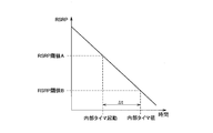
- FIG. 3 is a diagram for explaining an operation for detecting a rapid decrease in the RSRP measurement value.
- the RSRP monotonously decreases with time.
- the control unit 150 uses the ⁇ t that is the time difference from the time when the RSRP measurement value falls below the RSRP threshold A to the time when the RSRP measurement value falls below the RSRP threshold B, Detect a drop.
- the controller 150 starts the internal timer 160 when the RSRP measurement value falls below the RSRP threshold A, and measures ⁇ t by checking the timer value of the internal timer 160 when the RSRP measurement value falls below the RSRP threshold B. To do. When ⁇ t is equal to or less than the RSRP threshold B, it can be determined that the RSRP has rapidly decreased.
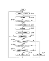
- FIG. 4 is a flowchart showing the operation of the radio terminal UE according to the present embodiment. This flow is started when the radio terminal UE is set from the E-UTRAN 10 to perform Immediate MDT. First, when this flow is started, the control unit 150 controls the measurement unit 120 to constantly measure RSRP.
- step S101 the control unit 150 resets the internal timer 160.
- step S102 the control unit 150 confirms the RSRP measurement value input from the measurement unit 120.
- step S103 the control unit 150 compares the RSRP measurement value confirmed in step S102 with the RSRP threshold A. When the RSRP measurement value confirmed in step S102 exceeds the RSRP threshold A, the control unit 150 returns the process to step S102. On the other hand, when the RSRP measurement value confirmed in step S102 is equal to or less than the RSRP threshold A, the control unit 150 advances the process to step S104. Measurement collection is performed after step S104.
- step S104 the control unit 150 starts the internal timer 160.
- step S105 the control unit 150 checks the RSRP measurement value input from the measurement unit 120.
- step S106 the control unit 150 checks the timer value input from the internal timer 160.
- step S107 the control unit 150 compares the RSRP measurement value confirmed in step S105 with the RSRP threshold A. When the RSRP measurement value confirmed in step S105 exceeds the RSRP threshold A, the control unit 150 returns the process to step S101. On the other hand, when the RSRP measurement value confirmed in step S105 is equal to or less than the RSRP threshold A, the control unit 150 advances the process to step S108.
- step S108 the control unit 150 compares the timer value confirmed in step S106 with the internal timer threshold value A. If the timer value confirmed in step S106 exceeds the internal timer threshold A, the control unit 150 advances the process to step S112. On the other hand, when the timer value confirmed in step S106 is equal to or smaller than the internal timer threshold A, the control unit 150 advances the process to step S109.
- step S112 since the RSRP measurement value does not rapidly decrease and the internal timer 160 times out and the reporting condition is satisfied, the control unit 150 controls to report the measurement data to the E-UTRAN 10. To do. Specifically, the control unit 150 outputs measurement data to the radio communication unit 110, and the radio communication unit 110 transmits the measurement data input from the control unit 150 to the connection destination base station eNB.
- step S109 the control unit 150 compares the RSRP measurement value confirmed in step S105 with the RSRP threshold value B. When the RSRP measurement value confirmed in step S105 exceeds the RSRP threshold B, the control unit 150 returns the process to step S105. On the other hand, when the RSRP measurement value confirmed in step S105 is equal to or less than the RSRP threshold B, the control unit 150 advances the process to step S110.
- step S110 the control unit 150 compares the timer value confirmed in step S106 with the internal timer threshold value B. If the timer value confirmed in step S106 exceeds the internal timer threshold B, the control unit 150 returns the process to step S105. On the other hand, if the timer value confirmed in step S106 is equal to or smaller than the internal timer threshold value B, the RSRP measurement value has rapidly decreased, and the control unit 150 advances the process to step S111.
- step S111 the control unit 150 stops reporting the measurement data by RLF, and returns the process to step S101.
- the radio terminal UE can avoid inducing inappropriate network optimization and increasing load and resource consumption.
- the predetermined time corresponding to the internal timer threshold B is set to a time shorter than a certain time corresponding to the internal timer threshold A.
- ⁇ t which is the time difference from the time when the RSRP measurement value falls below the RSRP threshold A to the time when it falls below the RSRP threshold B
- ⁇ t is acquired using the internal timer 160
- ⁇ t is Depending on whether or not the internal timer threshold value B is equal to or less than the internal timer threshold value B, it is determined whether or not the RSRP measurement value has rapidly decreased.
- the determination criterion is not limited to such a criterion, and a gradient of change calculated from the RSRP change amount in a certain time may be used as the criterion.
- the amount of decrease in the RSRP measurement value within a certain period of time is acquired, the amount of decrease is compared with a threshold value, and when the amount of decrease exceeds the threshold value, it is determined that the RSRP measurement value has rapidly decreased. Also good.
- the operation for enabling the reporting to be resumed after stopping the reporting of the measurement data has not been specifically described.
- the reporting can be resumed after the reporting of the measurement data is stopped. It is good.
- the control unit 150 of the radio terminal UE performs control so as to continue the state in which the measurement data reporting is stopped until the RSRP measurement value exceeds the RSRP threshold A after detecting that the RSRP measurement value has rapidly decreased. May be.
- RLF is used as a reporting condition.
- the reporting condition is not limited to RLF, and other reporting conditions such as Periodic, Serving celle comes worse than threshold (SCBWTT) may be used.
- Periodic is a reporting condition that reports periodically
- SCBWTT is a reporting condition that reports when RSRP measured for a serving cell falls below a threshold.
- a mobile communication system configured based on LTE for which specifications are defined in 3GPP has been described as an example.
- the mobile communication system is not limited to LTE, and is not limited to W-CDMA (Wideband Code Division Multiple Access) or the like.
- W-CDMA Wideband Code Division Multiple Access
- the present invention may be applied to other mobile communication systems.
- Immediate MDT is mainly described, but the present invention may be applied to Logged MDT.
- FIG. 1 is an overall schematic configuration diagram of a mobile communication system 1 according to the present embodiment.
- the mobile communication system 1 is configured based on LTE (Long Term Evolution) whose specifications are defined by 3GPP, and supports the above-described Logged MDT.
- LTE Long Term Evolution
- a mobile communication system 1 includes a radio terminal UE, an E-UTRAN (Evolved-UMTS Terrestrial Radio Access Network) 10, a mobility management device MME / gateway device S-GW, a maintenance monitoring device OAM,
- the E-UTRAN 10 is a mobile communication network composed of a plurality of base stations eNB.
- the radio terminal UE is a portable radio communication device possessed by the user.
- the radio terminal UE connects to any of the base stations eNB configuring the E-UTRAN 10 (including a case of connection via a relay device or a case of connection to a relay device), and a communication destination via the base station eNB It is configured to be able to communicate with.
- a state in which the radio terminal UE is executing communication is referred to as a connected mode, and a state in which the radio terminal UE is waiting is referred to as an idle mode.
- Each base station eNB is a fixed radio communication apparatus installed by an operator, and is configured to perform radio communication with the radio terminal UE.
- Each base station eNB performs communication with the mobility management apparatus MME / gateway apparatus S-GW and communication with the maintenance monitoring apparatus OAM via the backhaul.
- the mobility management device MME is configured to perform various types of mobility control for the radio terminal UE, and the gateway device S-GW is configured to perform transfer control of user data transmitted and received by the radio terminal UE.
- the maintenance monitoring device OAM is a server device installed by an operator, and is configured to perform maintenance and monitoring of the E-UTRAN 10.
- the base station eNB to which the radio terminal UE is connected transmits information for setting the Logged MDT to the radio terminal UE, for example, in response to an instruction from the maintenance monitoring apparatus OAM.
- the radio terminal UE set to perform Logged MDT measures and records the state of a received signal from the E-UTRAN 10 in the idle mode, and reports measurement data to the E-UTRAN 10 when shifting from the idle mode to the connected mode. .
- the process in which the radio terminal UE appropriately generates measurement data is referred to as “measurement collection”.
- reference signal received power (RSRP) is used as one index of the received signal state, but reference signal received quality (RSRQ) may be used together with RSRP.
- Measured data includes information on measurement results and position information at the time of measurement.
- the information related to the measurement result is information indicating RSRP for each cell of one or a plurality of base stations eNB, for example.
- the location information is GPS / GNSS location information when the radio terminal UE has a GPS / GNSS function, and is RF fingerprint information when the radio terminal UE does not have a GPS reception function. .
- the base station eNB that has received the measurement data from the radio terminal UE transfers the received measurement data to the maintenance monitoring device OAM.
- the maintenance monitoring apparatus OAM finds a coverage problem based on the measurement data obtained in this way, the maintenance monitoring apparatus OAM performs network optimization for notifying the operator of the found coverage problem or for eliminating the coverage problem.
- the base station eNB that performs the setting can specify various parameters related to the Logged MDT.
- the base station eNB that performs the setting specifies a recording condition (Logging / trigger) that is one of the parameters of Logging / MDT.
- the recording condition means a trigger for the radio terminal UE to record measurement data.
- Some coverage problems cannot be resolved even if normal network optimization is performed, depending on factors that cause RSRP degradation. For example, the problem that RSRP rapidly deteriorates when the radio terminal UE moves into an elevator and its door is closed cannot be solved even by performing normal network optimization. Therefore, it is preferable that such a coverage problem is not subject to network optimization.
- FIG. 5 is a block diagram showing a configuration of the radio terminal UE according to the present embodiment.
- the radio terminal UE has a GPS function.
- the radio terminal UE includes an antenna 101, a radio communication unit 110, a measurement unit 120, a GPS receiver 130, a storage unit 140, a control unit 150, an internal timer 160, and a battery 170. And have.
- the antenna 101 is used for transmitting and receiving radio signals.
- the wireless communication unit 110 is configured using, for example, a radio frequency (RF) circuit, a baseband (BB) circuit, or the like, and configured to perform wireless communication via the antenna 101.
- RF radio frequency
- BB baseband
- the wireless communication unit 110 encodes and modulates a transmission signal input from the control unit 150, performs up-conversion and amplification, and outputs the result to the antenna 101.
- the radio communication unit 110 performs amplification and down-conversion of the reception signal input from the antenna 101, performs demodulation and decoding, and outputs the result to the control unit 150.
- the measurement unit 120 measures the reception power level of the radio signal (specifically, the reference signal) received by the radio communication unit 110 from the E-UTRAN 10, that is, RSRP, and measures the measured RSRP (hereinafter referred to as “RSRP measurement value”). Output to the control unit 150.
- the GPS receiver 130 receives a signal from a GPS satellite and outputs GPS position information to the control unit 150.
- the storage unit 140 is configured using a memory, for example, and stores various types of information used for controlling the radio terminal UE and the like.
- the storage unit 140 stores various threshold values for detecting a rapid decrease in RSRP and the like, and setting information regarding LoggedLogMDT.
- the various threshold values include an RSRP threshold value A, an RSRP threshold value B, an internal timer threshold value A, and an internal timer threshold value B. Details of each threshold will be described later.
- the control unit 150 is configured using a CPU, for example, and controls various functions provided in the radio terminal UE.
- the control unit 150 generates measurement data in which the RSRP measurement value input from the measurement unit 120 and the position information input from the GPS receiver 130 are associated with each other according to the setting information stored in the storage unit 140.
- the measured data is temporarily held (cached) in the cache unit 150a.
- control unit 150 controls to record the measurement data temporarily stored in the cache unit 150 a in the storage unit 140 in accordance with the recording condition that is one of the setting information stored in the storage unit 140.
- control unit 150 controls the wireless communication unit 110 to report the measurement data recorded in the storage unit 140 to the E-UTRAN 10 when shifting from the idle mode to the connected mode.
- SCBWTT Serving celle comes worse than threshold
- SCBWTT is used as a recording condition.
- SCBWTT as a recording condition is recorded when measurement collection for a certain time is completed after the RSRP measurement value for the serving cell falls below the RSRP threshold A.
- the predetermined time is defined by an internal timer threshold A.
- the internal timer 160 is used for the control unit 150 to detect a rapid drop in RSRP.
- the internal timer 160 is activated when the RSRP measurement value falls below the RSRP threshold A by the control unit 150. After being started, the internal timer 160 outputs a timer value that increases as time elapses to the control unit 150.
- the battery 170 stores power to be supplied to each block of the radio terminal UE.
- the control unit 150 uses the timer value input from the internal timer 160 and the various threshold values stored in the storage unit 140 during the execution of the Logged MDT. A rapid drop in RSRP measurement from 120 is detected.
- the rapid decrease in the RSRP measurement value means that the RSRP measurement value has decreased by a predetermined amount corresponding to the difference between the RSRP threshold A and the RSRP threshold B within a predetermined time corresponding to the internal timer threshold B.
- the predetermined time corresponding to the internal timer threshold B is set to a time shorter than the predetermined time corresponding to the internal timer threshold A.
- control unit 150 When the control unit 150 detects a rapid decrease in the RSRP measurement value, the control unit 150 controls to exclude the measurement data corresponding to the RSRP measurement value indicating the rapid decrease from the report target to the E-UTRAN 10.
- the measurement data corresponding to the RSRP measurement value indicating a rapid decrease is, for example, from the start of measurement collection due to the RSRP measurement value falling below the RSRP threshold A to the detection of a rapid decrease in the RSRP measurement value. Means the measurement data for the period.
- control unit 150 when the control unit 150 detects a rapid decrease in the RSRP measurement value, the control unit 150 discards the measurement data corresponding to the RSRP measurement value indicating the rapid decrease without moving from the cache unit 150a to the storage unit 140. Shall.
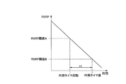
- FIG. 6 is a diagram for explaining an operation for detecting a rapid drop in the RSRP measurement value.
- the RSRP monotonously decreases with time.
- the control unit 150 uses the ⁇ t that is the time difference from the time when the RSRP measurement value falls below the RSRP threshold A to the time when the RSRP measurement value falls below the RSRP threshold B, Detect a drop.
- the controller 150 starts the internal timer 160 when the RSRP measurement value falls below the RSRP threshold A, and measures ⁇ t by checking the timer value of the internal timer 160 when the RSRP measurement value falls below the RSRP threshold B. To do. When ⁇ t is equal to or less than the RSRP threshold B, it can be determined that the RSRP has rapidly decreased.
- FIG. 7 is a flowchart showing the operation of the radio terminal UE according to this embodiment. This flow is started when the radio terminal UE is set from the E-UTRAN 10 to perform Logged MDT and then shifts to the idle mode. First, when this flow is started, the control unit 150 controls the measurement unit 120 to constantly measure RSRP.
- step S201 the control unit 150 resets the internal timer 160.
- step S202 the control unit 150 confirms the RSRP measurement value input from the measurement unit 120.
- step S203 the control unit 150 compares the RSRP measurement value confirmed in step S202 with the RSRP threshold A. When the RSRP measurement value confirmed in step S202 exceeds the RSRP threshold A, the control unit 150 returns the process to step S202. On the other hand, when the RSRP measurement value confirmed in step S202 is equal to or less than the RSRP threshold A, the control unit 150 advances the process to step S204.
- step S204 the control unit 150 starts the internal timer 160.
- step S205 the control unit 150 starts measurement collection.
- step S206 the control unit 150 confirms the RSRP measurement value input from the measurement unit 120.
- step S207 the control unit 150 checks the timer value input from the internal timer 160.
- step S208 the control unit 150 compares the RSRP measurement value confirmed in step S206 with the RSRP threshold A. When the RSRP measurement value confirmed in step S206 exceeds the RSRP threshold A, the control unit 150 returns the process to step S201. On the other hand, when the RSRP measurement value confirmed in step S206 is equal to or less than the RSRP threshold A, the control unit 150 advances the process to step S209.
- step S209 the control unit 150 compares the timer value confirmed in step S207 with the internal timer threshold value A. If the timer value confirmed in step S207 exceeds the internal timer threshold A, the control unit 150 advances the process to step S214. On the other hand, when the timer value confirmed in step S207 is equal to or smaller than the internal timer threshold A, the control unit 150 advances the process to step S210.
- step S214 since the RSRP measurement value does not rapidly decrease and the internal timer 160 times out and the recording condition is satisfied, the control unit 150 ends the measurement collection.
- step S215 the control unit 150 controls to record the measurement data temporarily stored in the cache unit 150a in the storage unit 140.
- step S210 the control unit 150 compares the RSRP measured value confirmed in step S206 with the RSRP threshold B. When the RSRP measurement value confirmed in step S206 exceeds the RSRP threshold B, the control unit 150 returns the process to step S206. On the other hand, when the RSRP measurement value confirmed in step S206 is equal to or less than the RSRP threshold B, the control unit 150 advances the process to step S211.
- step S211 the control unit 150 compares the timer value confirmed in step S207 with the internal timer threshold value B. If the timer value confirmed in step S207 exceeds the internal timer threshold B, the control unit 150 returns the process to step S206. On the other hand, if the timer value confirmed in step S207 is equal to or smaller than the internal timer threshold value B, the RSRP measurement value has rapidly decreased, and the control unit 150 advances the process to step S212.
- step S212 the control unit 150 ends the measurement collection.
- step S213 the control unit 150 discards the measurement data temporarily stored in the cache unit 150a without recording it in the storage unit 140.
- the measurement data related to the coverage problem that the RSRP rapidly decreases when the radio terminal UE moves into the elevator and the door is closed does not have to be reported to the E-UTRAN 10 when the mode is shifted to the connected mode.
- the coverage problem can be excluded from the network optimization target.
- the radio terminal UE can avoid inducing inappropriate network optimization and increasing load and resource consumption.
- the predetermined time corresponding to the internal timer threshold B is set to a time shorter than a certain time corresponding to the internal timer threshold A. This makes it possible to detect an abrupt decrease in the RSRP measurement value before the end of the recording period, thereby appropriately stopping measurement collection.
- the measurement data in the cache unit 150a is discarded without being recorded in the storage unit 140.
- the measurement collection may be continued until a time-out occurs without ending the measurement collection immediately.
- ⁇ t which is the time difference from the time when the RSRP measurement value falls below the RSRP threshold A to the time when it falls below the RSRP threshold B, is acquired using the internal timer 160, and ⁇ t is equal to or less than the internal timer threshold B. It was determined whether or not the RSRP measurement value suddenly decreased depending on whether or not.
- the determination criterion is not limited to such a criterion, and a gradient of change calculated from the RSRP change amount in a certain time may be used as the criterion.
- the amount of decrease in the RSRP measurement value within a certain period of time is acquired, the amount of decrease is compared with a threshold value, and when the amount of decrease exceeds the threshold value, it is determined that the RSRP measurement value has rapidly decreased. Also good.
- the operation for resuming the recording after stopping the recording of the measurement data has not been particularly described. However, the state in which the recording can be resumed after the recording of the measurement data is stopped. It is good. In this case, the control unit 150 of the radio terminal UE performs control so as to continue the state in which recording of measurement data is stopped until the RSRP measurement value exceeds the RSRP threshold A after detecting that the RSRP measurement value has rapidly decreased. May be.
- SCBWTT is used as a recording condition.
- the recording condition is not limited to SCBWTT, and other recording conditions such as Periodic, Transmit power headroom becomes less threshold may be used.
- Periodic is a recording condition for performing periodic recording
- TransmitTranspower headroom becomes less than threshold is a recording condition for performing recording when the transmission power margin falls below a threshold.
- a mobile communication system configured based on LTE for which specifications are defined in 3GPP has been described as an example, but not limited to LTE, W-CDMA (Wideband Code Division Multiple Multiple Access), etc.
- the present invention may be applied to other mobile communication systems.
- FIG. 1 is an overall schematic configuration diagram of a mobile communication system 1 according to the present embodiment.
- the mobile communication system 1 is configured based on LTE (Long Term Evolution) whose specifications are defined by 3GPP, and supports the above-described Logged MDT.
- LTE Long Term Evolution
- a mobile communication system 1 includes a radio terminal UE, an E-UTRAN (Evolved-UMTS Terrestrial Radio Access Network) 10, a mobility management device MME / gateway device S-GW, a maintenance monitoring device OAM,
- the E-UTRAN 10 is a mobile communication network composed of a plurality of base stations eNB.
- the radio terminal UE is a portable radio communication device possessed by the user.
- the radio terminal UE connects to any of the base stations eNB configuring the E-UTRAN 10 (including a case of connection via a relay device or a case of connection to a relay device), and a communication destination via the base station eNB It is configured to be able to communicate with.
- a state in which the radio terminal UE is executing communication is referred to as a connected mode, and a state in which the radio terminal UE is waiting is referred to as an idle mode.
- Each base station eNB is a fixed radio communication apparatus installed by an operator, and is configured to perform radio communication with the radio terminal UE.
- Each base station eNB performs communication with the mobility management device MME / gateway device S-GW and communication with the maintenance monitoring device OAM via the backhaul.
- the mobility management device MME is configured to perform various types of mobility control for the radio terminal UE, and the gateway device S-GW is configured to perform transfer control of user data transmitted and received by the radio terminal UE.
- the maintenance monitoring device OAM is a server device installed by an operator, and is configured to perform maintenance and monitoring of the E-UTRAN 10.
- the base station eNB to which the radio terminal UE is connected transmits information for setting the Logged MDT to the radio terminal UE, for example, in response to an instruction from the maintenance monitoring apparatus OAM.
- the radio terminal UE set to perform Logged MDT measures and records the state of a received signal from the E-UTRAN 10 in the idle mode, and reports measurement data to the E-UTRAN 10 when shifting from the idle mode to the connected mode. .
- the process in which the radio terminal UE appropriately generates measurement data is referred to as “measurement collection”.
- reference signal received power (RSRP) is used as one index of the received signal state, but reference signal received quality (RSRQ) may be used together with RSRP.
- Measured data includes information on measurement results and position information at the time of measurement.
- the information related to the measurement result is information indicating RSRP for each cell of one or a plurality of base stations eNB, for example.
- the location information is GPS / GNSS location information when the radio terminal UE has a GPS / GNSS function, and is RF fingerprint information when the radio terminal UE does not have a GPS reception function. .
- the base station eNB that has received the measurement data from the radio terminal UE transfers the received measurement data to the maintenance monitoring device OAM.
- the maintenance monitoring apparatus OAM finds a coverage problem based on the measurement data obtained in this way, the maintenance monitoring apparatus OAM performs network optimization for notifying the operator of the found coverage problem or for eliminating the coverage problem.
- the base station eNB that performs the setting can specify various parameters related to the Logged MDT.
- the base station eNB that performs the setting specifies a recording condition (Logging / trigger) that is one of the parameters of Logging / MDT.
- the recording condition means a trigger for the radio terminal UE to record measurement data.
- Some coverage problems cannot be resolved even if normal network optimization is performed, depending on factors that cause RSRP degradation. For example, the problem that RSRP rapidly deteriorates when the radio terminal UE moves into an elevator and its door is closed cannot be solved even by performing normal network optimization. Therefore, it is preferable that such a coverage problem is not subject to network optimization.
- the radio terminal UE set to perform Logged MDT detects an abrupt decrease in RSRP in the idle mode, it deletes all recorded measurement data.
- FIG. 8 is a block diagram showing a configuration of the radio terminal UE according to this embodiment.
- the radio terminal UE has a GPS function.
- the radio terminal UE includes an antenna 101, a radio communication unit 110, a measurement unit 120, a GPS receiver 130, a storage unit 140, a control unit 150, an internal timer 160, and a battery 170. And have.
- the antenna 101 is used for transmitting and receiving radio signals.
- the wireless communication unit 110 is configured using, for example, a radio frequency (RF) circuit, a baseband (BB) circuit, or the like, and configured to perform wireless communication via the antenna 101.
- RF radio frequency
- BB baseband
- the wireless communication unit 110 encodes and modulates a transmission signal input from the control unit 150, performs up-conversion and amplification, and outputs the result to the antenna 101.
- the radio communication unit 110 performs amplification and down-conversion of the reception signal input from the antenna 101, performs demodulation and decoding, and outputs the result to the control unit 150.
- the measurement unit 120 measures the reception power level of the radio signal (specifically, the reference signal) received by the radio communication unit 110 from the E-UTRAN 10, that is, RSRP, and measures the measured RSRP (hereinafter referred to as “RSRP measurement value”). Output to the control unit 150.
- the GPS receiver 130 receives a signal from a GPS satellite and outputs GPS position information to the control unit 150.
- the storage unit 140 is configured using a memory, for example, and stores various types of information used for controlling the radio terminal UE and the like.
- the storage unit 140 stores various threshold values for detecting a rapid decrease in RSRP and the like, and setting information regarding LoggedLogMDT.
- the various threshold values include an RSRP threshold value A, an RSRP threshold value B, an internal timer threshold value A, and an internal timer threshold value B. Details of each threshold will be described later.
- the control unit 150 is configured using a CPU, for example, and controls various functions provided in the radio terminal UE.
- the control unit 150 generates measurement data in which the RSRP measurement value input from the measurement unit 120 and the position information input from the GPS receiver 130 are associated with each other according to the setting information stored in the storage unit 140.
- the measured data is controlled to be recorded in the storage unit 140.
- the control unit 150 controls the measurement data recorded in the storage unit 140 to be reported from the wireless communication unit 110 to the E-UTRAN 10 when shifting from the idle mode to the connected mode.
- SCBWTT Serving celle comes worse than threshold
- SCBWTT is used as a recording condition included in the setting information.
- SCBWTT as a recording condition is to perform recording for a certain time after the RSRP measurement value for the serving cell falls below the RSRP threshold A.
- the predetermined time is defined by an internal timer threshold A.
- the internal timer 160 is used for the control unit 150 to detect a rapid drop in RSRP.
- the internal timer 160 is activated when the RSRP measurement value falls below the RSRP threshold A by the control unit 150. After being started, the internal timer 160 outputs a timer value that increases as time elapses to the control unit 150.
- the battery 170 stores power to be supplied to each block of the radio terminal UE.
- the control unit 150 uses the timer value input from the internal timer 160 and the various threshold values stored in the storage unit 140 during the execution of the Logged MDT.
- a rapid drop in RSRP measurement from 120 is detected.
- the rapid decrease in the RSRP measurement value means that the RSRP measurement value has decreased by a predetermined amount corresponding to the difference between the RSRP threshold A and the RSRP threshold B within a predetermined time corresponding to the internal timer threshold B.
- the predetermined time corresponding to the internal timer threshold B is set to a time shorter than the predetermined time corresponding to the internal timer threshold A.
- control unit 150 detects a rapid decrease in the RSRP measurement value, the control unit 150 controls to delete all measurement data recorded in the storage unit 140.
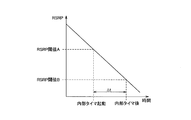
- FIG. 9 is a diagram for explaining an operation for detecting a rapid drop in the RSRP measurement value.
- the RSRP monotonously decreases with time.
- the control unit 150 uses the ⁇ t that is a time difference from the time when the RSRP measurement value falls below the RSRP threshold A to the time when the RSRP measurement value falls below the RSRP threshold B, to rapidly increase the RSRP. Detect a drop.
- the controller 150 starts the internal timer 160 when the RSRP measurement value falls below the RSRP threshold A, and measures ⁇ t by checking the timer value of the internal timer 160 when the RSRP measurement value falls below the RSRP threshold B. To do. When ⁇ t is equal to or less than the RSRP threshold B, it can be determined that the RSRP has rapidly decreased.
- FIG. 10 is a flowchart showing the operation of the radio terminal UE according to this embodiment. This flow is started when the radio terminal UE is set from the E-UTRAN 10 to perform Logged MDT and then shifts to the idle mode. First, when this flow is started, the control unit 150 controls the measurement unit 120 to constantly measure RSRP.
- step S301 the control unit 150 resets the internal timer 160.
- step S302 the control unit 150 resets the invalid data presence flag.
- the invalid data presence flag is a flag for specifying invalid measurement data.
- step S303 the control unit 150 confirms the RSRP measurement value input from the measurement unit 120.
- step S304 the control unit 150 compares the RSRP measurement value confirmed in step S303 with the RSRP threshold A. When the RSRP measurement value confirmed in step S303 exceeds the RSRP threshold A, the control unit 150 returns the process to step S303. On the other hand, when the RSRP measurement value confirmed in step S303 is equal to or less than the RSRP threshold A, the control unit 150 advances the process to step S305.
- step S305 the control unit 150 starts the internal timer 160.
- step S306 the control unit 150 starts measurement collection. Further, in step S307, the control unit 150 starts recording measurement data.
- step S308 the control unit 150 confirms the RSRP measurement value input from the measurement unit 120.
- step S309 the control unit 150 checks the timer value input from the internal timer 160.
- step S310 the control unit 150 compares the RSRP measurement value confirmed in step S308 with the RSRP threshold A.
- the control unit 150 advances the process to step S315.
- the control unit 150 advances the process to step S311.
- step S311 the control unit 150 compares the timer value confirmed in step S309 with the internal timer threshold value A. If the timer value confirmed in step S309 exceeds the internal timer threshold A, the control unit 150 advances the process to step S315. On the other hand, when the timer value confirmed in step S309 is equal to or smaller than the internal timer threshold A, the control unit 150 advances the process to step S312.
- step S312 the control unit 150 compares the RSRP measured value confirmed in step S308 with the RSRP threshold B. When the RSRP measurement value confirmed in step S308 exceeds the RSRP threshold B, the control unit 150 returns the process to step S308. On the other hand, when the RSRP measurement value confirmed in step S308 is equal to or less than the RSRP threshold B, the control unit 150 advances the process to step S313.
- step S313 the control unit 150 compares the timer value confirmed in step S309 with the internal timer threshold value B. If the timer value confirmed in step S309 exceeds the internal timer threshold value B, the control unit 150 returns the process to step S308. On the other hand, if the timer value confirmed in step S309 is equal to or smaller than the internal timer threshold value B, the RSRP measurement value has rapidly decreased, and the control unit 150 advances the process to step S314.
- step S314 the control unit 150 stores an invalid data presence flag.
- control unit 150 ends the measurement collection.
- control part 150 ends recording of measurement data.
- step S317 the control unit 150 checks the presence or absence of invalid measurement data according to the presence or absence of an invalid data presence flag. If there is an invalid data presence flag, that is, if there is invalid measurement data, the control unit 150 advances the process to step S318. On the other hand, when there is no invalid data presence flag, that is, when there is no invalid measurement data, the control unit 150 returns the process to step S301.
- step S318 the control unit 150 deletes all measurement data stored in the storage unit 140. Thereafter, the process returns to step S301.
- the timing for deleting the measurement data may be any timing as long as it is before the transition from the idle mode to the connected mode.
- the storage unit Control is performed to delete all the measurement data stored in 140.
- the measurement data related to the coverage problem that the RSRP rapidly decreases when the radio terminal UE moves into the elevator and the door is closed does not have to be reported to the E-UTRAN 10 when the mode is shifted to the connected mode.
- the coverage problem can be excluded from the network optimization target.
- the radio terminal UE can avoid inducing inappropriate network optimization and increasing load and resource consumption.
- the predetermined time corresponding to the internal timer threshold B is set to a time shorter than a certain time corresponding to the internal timer threshold A. This makes it possible to detect an abrupt decrease in the RSRP measurement value before the end of the recording period, thereby appropriately stopping measurement collection.
- measurement collection is started after the RSRP measurement value falls below the RSRP threshold A.
- measurement data before the RSRP measurement value falls below the RSRP threshold A is also E-UTRAN10. If it is necessary to report to, measurement collection may be performed after step S301 and before step S305.
- measurement collection is stopped when the received signal state is improved before the timeout.
- the measurement collection may be continued until a time-out occurs without ending the measurement collection immediately.
- ⁇ t which is the time difference from the time when the RSRP measurement value falls below the RSRP threshold A to the time when it falls below the RSRP threshold B, is acquired using the internal timer 160, and ⁇ t is equal to or less than the internal timer threshold B. It was determined whether or not the RSRP measurement value suddenly decreased depending on whether or not.
- the determination criterion is not limited to such a criterion, and a gradient of change calculated from the RSRP change amount in a certain time may be used as the criterion.
- the amount of decrease in the RSRP measurement value within a certain period of time is acquired, the amount of decrease is compared with a threshold value, and when the amount of decrease exceeds the threshold value, it is determined that the RSRP measurement value has rapidly decreased. Also good.
- SCBWTT is used as a recording condition.
- the recording condition is not limited to SCBWTT, and other recording conditions such as Periodic, Transmit power headroom becomes less threshold may be used.
- Periodic is a recording condition for performing periodic recording
- TransmitTranspower headroom becomes less than threshold is a recording condition for performing recording when the transmission power margin falls below a threshold.
- a mobile communication system configured based on LTE for which specifications have been formulated in 3GPP has been described as an example.
- LTE Long Term Evolution
- W-CDMA Wideband Code (Division Multiple Access)
- the present invention may be applied to other mobile communication systems.
- FIG. 1 is an overall schematic configuration diagram of a mobile communication system 1 according to the present embodiment.
- the mobile communication system 1 is configured based on LTE (Long Term Evolution) whose specifications are defined by 3GPP, and supports the above-described Logged MDT.
- LTE Long Term Evolution
- a mobile communication system 1 includes a radio terminal UE, an E-UTRAN (Evolved-UMTS Terrestrial Radio Access Network) 10, a mobility management device MME / gateway device S-GW, a maintenance monitoring device OAM,
- the E-UTRAN 10 is a mobile communication network composed of a plurality of base stations eNB.
- the radio terminal UE is a portable radio communication device possessed by the user.
- the radio terminal UE connects to any of the base stations eNB configuring the E-UTRAN 10 (including a case of connection via a relay device or a case of connection to a relay device), and a communication destination via the base station eNB It is configured to be able to communicate with.
- a state in which the radio terminal UE is executing communication is referred to as a connected mode, and a state in which the radio terminal UE is waiting is referred to as an idle mode.
- Each base station eNB is a fixed radio communication apparatus installed by an operator, and is configured to perform radio communication with the radio terminal UE.
- Each base station eNB performs communication with the mobility management device MME / gateway device S-GW and communication with the maintenance monitoring device OAM via the backhaul.
- the mobility management device MME is configured to perform various types of mobility control for the radio terminal UE, and the gateway device S-GW is configured to perform transfer control of user data transmitted and received by the radio terminal UE.
- the maintenance monitoring device OAM is a server device installed by an operator, and is configured to perform maintenance and monitoring of the E-UTRAN 10.
- the base station eNB to which the radio terminal UE is connected transmits information for setting the Logged MDT to the radio terminal UE, for example, in response to an instruction from the maintenance monitoring apparatus OAM.
- the radio terminal UE set to perform Logged MDT measures and records the state of a received signal from the E-UTRAN 10 in the idle mode, and reports measurement data to the E-UTRAN 10 when shifting from the idle mode to the connected mode. .
- the process in which the radio terminal UE appropriately generates measurement data is referred to as “measurement collection”.
- reference signal received power (RSRP) is used as one index of the received signal state, but reference signal received quality (RSRQ) may be used together with RSRP.
- Measured data includes information on measurement results and position information at the time of measurement.
- the information related to the measurement result is information indicating RSRP for each cell of one or a plurality of base stations eNB, for example.
- the location information is GPS / GNSS location information when the radio terminal UE has a GPS / GNSS function, and is RF fingerprint information when the radio terminal UE does not have a GPS reception function. .
- the base station eNB that has received the measurement data from the radio terminal UE transfers the received measurement data to the maintenance monitoring device OAM.
- the maintenance monitoring apparatus OAM finds a coverage problem based on the measurement data obtained in this way, the maintenance monitoring apparatus OAM performs network optimization for notifying the operator of the found coverage problem or for eliminating the coverage problem.
- the base station eNB that performs the setting can specify various parameters related to the Logged MDT.
- the base station eNB that performs the setting specifies a recording condition (Logging / trigger) that is one of the parameters of Logging / MDT.
- the recording condition means a trigger for the radio terminal UE to record measurement data.
- Some coverage problems cannot be resolved even if normal network optimization is performed, depending on factors that cause RSRP degradation. For example, the problem that RSRP rapidly deteriorates when the radio terminal UE moves into an elevator and its door is closed cannot be solved even by performing normal network optimization. Therefore, it is preferable that such a coverage problem is not subject to network optimization.
- the radio terminal UE set to perform Logged MDT detects an abrupt decrease in RSRP in the idle mode
- the RSRP indicating the abrupt decrease in the recorded measurement data is displayed. Delete the corresponding measurement data.
- FIG. 11 is a block diagram showing a configuration of the radio terminal UE according to this embodiment.
- the radio terminal UE has a GPS function.
- the radio terminal UE includes an antenna 101, a radio communication unit 110, a measurement unit 120, a GPS receiver 130, a storage unit 140, a control unit 150, an internal timer 160, and a battery 170. And have.
- the antenna 101 is used for transmitting and receiving radio signals.
- the wireless communication unit 110 is configured using, for example, a radio frequency (RF) circuit, a baseband (BB) circuit, or the like, and configured to perform wireless communication via the antenna 101.
- RF radio frequency
- BB baseband
- the wireless communication unit 110 encodes and modulates a transmission signal input from the control unit 150, performs up-conversion and amplification, and outputs the result to the antenna 101.
- the radio communication unit 110 performs amplification and down-conversion of the reception signal input from the antenna 101, performs demodulation and decoding, and outputs the result to the control unit 150.
- the measurement unit 120 measures the reception power level of the radio signal (specifically, the reference signal) received by the radio communication unit 110 from the E-UTRAN 10, that is, RSRP, and measures the measured RSRP (hereinafter referred to as “RSRP measurement value”). Output to the control unit 150.
- the GPS receiver 130 receives a signal from a GPS satellite and outputs GPS position information to the control unit 150.
- the storage unit 140 is configured using a memory, for example, and stores various types of information used for controlling the radio terminal UE and the like.
- the storage unit 140 stores various threshold values for detecting a rapid decrease in RSRP and the like, and setting information regarding LoggedLogMDT.
- the various threshold values include an RSRP threshold value A, an RSRP threshold value B, an internal timer threshold value A, and an internal timer threshold value B. Details of each threshold will be described later.
- the control unit 150 is configured using a CPU, for example, and controls various functions provided in the radio terminal UE.
- the control unit 150 generates measurement data in which the RSRP measurement value input from the measurement unit 120 and the position information input from the GPS receiver 130 are associated with each other according to the setting information stored in the storage unit 140.
- the measured data is controlled to be recorded in the storage unit 140.
- the control unit 150 controls the measurement data recorded in the storage unit 140 to be reported from the wireless communication unit 110 to the E-UTRAN 10 when shifting from the idle mode to the connected mode.
- SCBWTT Serving celle comes worse than threshold
- SCBWTT is used as a recording condition included in the setting information.
- SCBWTT as a recording condition is to perform recording for a certain time after the RSRP measurement value for the serving cell falls below the RSRP threshold A.
- the predetermined time is defined by an internal timer threshold A.
- the internal timer 160 is used for the control unit 150 to detect a rapid drop in RSRP.
- the internal timer 160 is activated when the RSRP measurement value falls below the RSRP threshold A by the control unit 150. After being started, the internal timer 160 outputs a timer value that increases as time elapses to the control unit 150.
- the battery 170 stores power to be supplied to each block of the radio terminal UE.
- the control unit 150 uses the timer value input from the internal timer 160 and the various threshold values stored in the storage unit 140 during the execution of the Logged MDT. A rapid drop in RSRP measurement from 120 is detected.
- the rapid decrease in the RSRP measurement value means that the RSRP measurement value has decreased by a predetermined amount corresponding to the difference between the RSRP threshold A and the RSRP threshold B within a predetermined time corresponding to the internal timer threshold B.
- the predetermined time corresponding to the internal timer threshold B is set to a time shorter than the predetermined time corresponding to the internal timer threshold A.
- the controller 150 controls to delete the measurement data corresponding to the RSRP that showed the rapid decrease from the measurement data recorded in the storage unit 140.
- the measurement data corresponding to RSRP showing a rapid decrease was obtained, for example, in the period from the time when measurement collection was started due to the RSRP measurement value falling below the RSRP threshold A to the time when measurement collection was terminated. Means measurement data.
- FIG. 12 is a diagram for explaining an operation of detecting a rapid decrease in the RSRP measurement value.
- the RSRP monotonously decreases with time.
- the control unit 150 uses the ⁇ t that is a time difference from the time when the RSRP measurement value falls below the RSRP threshold A to the time when the RSRP measurement value falls below the RSRP threshold B. Detect a drop.
- the controller 150 starts the internal timer 160 when the RSRP measurement value falls below the RSRP threshold A, and measures ⁇ t by checking the timer value of the internal timer 160 when the RSRP measurement value falls below the RSRP threshold B. To do. When ⁇ t is equal to or less than the RSRP threshold B, it can be determined that the RSRP has rapidly decreased.
- FIG. 13 is a flowchart showing the operation of the radio terminal UE according to this embodiment. This flow is started when the radio terminal UE is set from the E-UTRAN 10 to perform Logged MDT and then shifts to the idle mode. First, when this flow is started, the control unit 150 controls the measurement unit 120 to constantly measure RSRP.
- step S401 the control unit 150 resets the internal timer 160.
- step S402 the control unit 150 resets the invalid data presence flag.
- the invalid data presence flag is a flag for specifying invalid measurement data.
- step S403 the control unit 150 confirms the RSRP measurement value input from the measurement unit 120.
- step S404 the control unit 150 compares the RSRP measurement value confirmed in step S403 with the RSRP threshold A. When the RSRP measurement value confirmed in step S403 exceeds the RSRP threshold A, the control unit 150 returns the process to step S403. On the other hand, when the RSRP measurement value confirmed in step S403 is equal to or less than the RSRP threshold A, the control unit 150 advances the process to step S405.
- step S405 the control unit 150 starts the internal timer 160.
- step S406 the control unit 150 stores the measurement collection start time. Specifically, the control unit 150 has a clock function for obtaining the current time, acquires the measurement collection start time using the clock function, and stores the acquired measurement collection start time. In step S407, the control unit 150 starts measurement collection. Further, in step S408, the control unit 150 starts recording measurement data.
- step S409 the control unit 150 checks the RSRP measurement value input from the measurement unit 120.
- step S410 the control unit 150 confirms the timer value input from the internal timer 160.
- step S411 the control unit 150 compares the RSRP measurement value confirmed in step S409 with the RSRP threshold A. If the RSRP measurement value confirmed in step S409 exceeds the RSRP threshold A, the control unit 150 advances the process to step S416. On the other hand, when the RSRP measurement value confirmed in step S409 is equal to or less than the RSRP threshold A, the control unit 150 advances the process to step S412.
- step S412 the control unit 150 compares the timer value confirmed in step S410 with the internal timer threshold value A. If the timer value confirmed in step S410 exceeds the internal timer threshold A, the control unit 150 advances the process to step S416. On the other hand, if the timer value confirmed in step S410 is equal to or smaller than the internal timer threshold A, the control unit 150 advances the process to step S413.
- step S413 the control unit 150 compares the RSRP measurement value confirmed in step S409 with the RSRP threshold B. When the RSRP measurement value confirmed in step S409 exceeds the RSRP threshold B, the control unit 150 returns the process to step S409. On the other hand, when the RSRP measurement value confirmed in step S409 is equal to or less than the RSRP threshold B, the control unit 150 advances the process to step S414.
- step S414 the control unit 150 compares the timer value confirmed in step S410 with the internal timer threshold value B. If the timer value confirmed in step S410 exceeds the internal timer threshold B, the control unit 150 returns the process to step S409. On the other hand, if the timer value confirmed in step S410 is equal to or smaller than the internal timer threshold value B, the RSRP measurement value has rapidly decreased, and the control unit 150 advances the process to step S415.
- step S415 the control unit 150 stores an invalid data presence flag.
- step S416 the control unit 150 ends the measurement collection.
- step S417 the control unit 150 ends the recording of the measurement data.
- step S4108 the control unit 150 confirms the presence or absence of invalid measurement data according to the presence or absence of an invalid data presence flag. If there is an invalid data presence flag, that is, if there is invalid measurement data, the control unit 150 advances the process to step S419. On the other hand, when there is no invalid data presence flag, that is, when there is no invalid measurement data, the control unit 150 returns the process to step S401.
- step S419 the control unit 150 stores the measurement collection end time. Specifically, the control unit 150 acquires the measurement collection end time using the clock function, and stores the acquired measurement collection end time.
- step S420 the control unit 150 measures the measurement data obtained in the period from the measurement collection start time stored in step S406 to the measurement collection end time stored in step S419, among the measurement data stored in the storage unit 140. Is deleted. Note that the timing for deleting the measurement data may be any timing as long as it is before the transition from the idle mode to the connected mode.
- the measurement data related to the coverage problem that the RSRP rapidly decreases when the radio terminal UE moves into the elevator and the door is closed does not have to be reported to the E-UTRAN 10 when the mode is shifted to the connected mode.
- the coverage problem can be excluded from the network optimization target.
- the radio terminal UE can avoid inducing inappropriate network optimization and increasing load and resource consumption.
- the predetermined time corresponding to the internal timer threshold B is set to a time shorter than a certain time corresponding to the internal timer threshold A. This makes it possible to detect an abrupt decrease in the RSRP measurement value before the end of the recording period, thereby appropriately stopping measurement collection.
- the measurement collection start time and the measurement collection end time are stored, and the measurement data obtained between the two times is specified as a deletion target.
- the measurement collection start time and the measurement collection end time are not only stored, but after the measurement collection start ID is recorded in the storage unit 140, the measurement data is recorded in the storage unit 140, and then the measurement collection end is performed in the storage unit 140.
- the measurement data between both IDs may be specified as a deletion target.
- measurement collection is started after the RSRP measurement value falls below the RSRP threshold A. However, it is necessary to report the measurement data before the RSRP measurement value falls below the RSRP threshold A to the E-UTRAN 10 as well. In some cases, measurement collection may be performed after step S401 and before step S407.
- measurement collection is stopped when the received signal state is improved before the timeout.
- the measurement collection may be continued until a time-out occurs without ending the measurement collection immediately.
- ⁇ t which is the time difference from the time when the RSRP measurement value falls below the RSRP threshold A to the time when it falls below the RSRP threshold B, is obtained using the internal timer 160, and ⁇ t is equal to or less than the internal timer threshold B. It was determined whether or not the RSRP measurement value suddenly decreased depending on whether or not.
- the determination criterion is not limited to such a criterion, and a gradient of change calculated from the RSRP change amount in a certain time may be used as the criterion.
- the amount of decrease in the RSRP measurement value within a certain period of time is acquired, the amount of decrease is compared with a threshold value, and when the amount of decrease exceeds the threshold value, it is determined that the RSRP measurement value has rapidly decreased. Also good.
- SCBWTT is used as the recording condition.
- other recording conditions such as Periodic, Transmit power headroom becomes less threshold may be used instead of SCBWTT.
- Periodic is a recording condition for performing periodic recording
- TransmitTranspower headroom becomes less than threshold is a recording condition for performing recording when the transmission power margin falls below a threshold.
- a mobile communication system configured based on LTE for which specifications are defined in 3GPP has been described as an example.
- the mobile communication system is not limited to LTE, and is not limited to LTE, such as W-CDMA (Wideband Code Division ⁇ Multiple Access).
- W-CDMA Wideband Code Division ⁇ Multiple Access
- the present invention may be applied to other mobile communication systems.
- the wireless terminal and the control method according to the present invention are useful in the wireless communication field because they can avoid inappropriate network optimization or increase load and resource consumption. .
Landscapes
- Engineering & Computer Science (AREA)
- Computer Networks & Wireless Communication (AREA)
- Signal Processing (AREA)
- Physics & Mathematics (AREA)
- Electromagnetism (AREA)
- Quality & Reliability (AREA)
- Mobile Radio Communication Systems (AREA)
Abstract
Priority Applications (4)
| Application Number | Priority Date | Filing Date | Title |
|---|---|---|---|
| EP12755682.7A EP2685754A4 (fr) | 2011-03-08 | 2012-03-07 | Terminal sans fil et procédé de régulation |
| US14/003,763 US9100865B2 (en) | 2011-03-08 | 2012-03-07 | Radio terminal and control method |
| KR1020137023784A KR20130141663A (ko) | 2011-03-08 | 2012-03-07 | 무선단말 및 제어방법 |
| CN2012800119221A CN103416084A (zh) | 2011-03-08 | 2012-03-07 | 无线终端和控制方法 |
Applications Claiming Priority (8)
| Application Number | Priority Date | Filing Date | Title |
|---|---|---|---|
| JP2011-050585 | 2011-03-08 | ||
| JP2011050585A JP5705594B2 (ja) | 2011-03-08 | 2011-03-08 | 無線端末及び制御方法 |
| JP2011-050613 | 2011-03-08 | ||
| JP2011050588A JP5705595B2 (ja) | 2011-03-08 | 2011-03-08 | 無線端末及び制御方法 |
| JP2011-050588 | 2011-03-08 | ||
| JP2011050611A JP5705596B2 (ja) | 2011-03-08 | 2011-03-08 | 無線端末及び制御方法 |
| JP2011050613A JP5705597B2 (ja) | 2011-03-08 | 2011-03-08 | 無線端末及び制御方法 |
| JP2011-050611 | 2011-03-08 |
Publications (1)
| Publication Number | Publication Date |
|---|---|
| WO2012121303A1 true WO2012121303A1 (fr) | 2012-09-13 |
Family
ID=46798259
Family Applications (1)
| Application Number | Title | Priority Date | Filing Date |
|---|---|---|---|
| PCT/JP2012/055874 WO2012121303A1 (fr) | 2011-03-08 | 2012-03-07 | Terminal sans fil et procédé de régulation |
Country Status (5)
| Country | Link |
|---|---|
| US (1) | US9100865B2 (fr) |
| EP (1) | EP2685754A4 (fr) |
| KR (1) | KR20130141663A (fr) |
| CN (1) | CN103416084A (fr) |
| WO (1) | WO2012121303A1 (fr) |
Families Citing this family (5)
| Publication number | Priority date | Publication date | Assignee | Title |
|---|---|---|---|---|
| WO2015045701A1 (fr) * | 2013-09-26 | 2015-04-02 | シャープ株式会社 | Système de communication sans fil, appareil de terminal, procédé de communication sans fil et circuit intégré |
| CN106133309B (zh) * | 2014-03-25 | 2019-10-01 | Ntn株式会社 | 状态监测系统 |
| KR102386570B1 (ko) * | 2015-09-10 | 2022-04-13 | 광동 오포 모바일 텔레커뮤니케이션즈 코포레이션 리미티드 | 채널 측정 및 측정 결과 리포팅 방법 및 장치 |
| US10856230B2 (en) * | 2017-09-13 | 2020-12-01 | Apple Inc. | Low power measurements mode |
| CN110324834B (zh) * | 2018-03-28 | 2021-06-04 | 维沃移动通信有限公司 | 测量结果的指示方法、终端和基站 |
Citations (2)
| Publication number | Priority date | Publication date | Assignee | Title |
|---|---|---|---|---|
| JP2005101971A (ja) * | 2003-09-25 | 2005-04-14 | Sanyo Electric Co Ltd | 受信方法およびそれを利用した無線通信装置 |
| JP2009164876A (ja) * | 2008-01-07 | 2009-07-23 | Hitachi Kokusai Electric Inc | 無線通信システムにおける電界強度測定方法 |
Family Cites Families (8)
| Publication number | Priority date | Publication date | Assignee | Title |
|---|---|---|---|---|
| FI103081B (fi) * | 1996-02-23 | 1999-04-15 | Nokia Telecommunications Oy | Kanavanvaihto matkaviestinjärjestelmässä |
| US7430432B2 (en) * | 2004-09-02 | 2008-09-30 | Nokia Corporation | Apparatus, and associated method, for calculating communication channel indications for use in a radio communication system that utilizes closed-loop power control |
| CN101369822B (zh) * | 2007-08-13 | 2012-04-25 | 电信科学技术研究院 | 一种通过公共信道确定小区覆盖范围的方法及装置 |
| CN103024804B (zh) | 2007-09-26 | 2016-03-02 | 日本电气株式会社 | 无线通信系统和方法 |
| JP5333228B2 (ja) * | 2007-10-11 | 2013-11-06 | 日本電気株式会社 | 無線通信システム及び方法 |
| JP5262894B2 (ja) | 2009-03-24 | 2013-08-14 | 富士通株式会社 | 無線通信システムにおける復号誤り検出方法および復号装置 |
| CN101527974B (zh) * | 2009-04-10 | 2011-09-28 | 山东大学 | 优化城区cmmb网络的cmmb直放站及其控制方法 |
| CN101902752A (zh) * | 2010-05-21 | 2010-12-01 | 南京邮电大学 | 一种有向传感器网络覆盖控制方法 |
-
2012
- 2012-03-07 KR KR1020137023784A patent/KR20130141663A/ko not_active Application Discontinuation
- 2012-03-07 EP EP12755682.7A patent/EP2685754A4/fr not_active Withdrawn
- 2012-03-07 US US14/003,763 patent/US9100865B2/en not_active Expired - Fee Related
- 2012-03-07 CN CN2012800119221A patent/CN103416084A/zh active Pending
- 2012-03-07 WO PCT/JP2012/055874 patent/WO2012121303A1/fr active Application Filing
Patent Citations (2)
| Publication number | Priority date | Publication date | Assignee | Title |
|---|---|---|---|---|
| JP2005101971A (ja) * | 2003-09-25 | 2005-04-14 | Sanyo Electric Co Ltd | 受信方法およびそれを利用した無線通信装置 |
| JP2009164876A (ja) * | 2008-01-07 | 2009-07-23 | Hitachi Kokusai Electric Inc | 無線通信システムにおける電界強度測定方法 |
Non-Patent Citations (4)
| Title |
|---|
| "Radio measurement collection for Minimization of Drive Tests (MDT); Overall description; Stage 2", 3GPP TS 37.320 V10.0.0, December 2010 (2010-12-01) |
| "Study on Minimization of drive-tests in Next Generation Networks", 3GPP TR 36.805 V9.0.0, December 2009 (2009-12-01) |
| 3GPP TS 37.320 V10.0.0 (2010-12), XP050462200 * |
| See also references of EP2685754A4 * |
Also Published As
| Publication number | Publication date |
|---|---|
| US9100865B2 (en) | 2015-08-04 |
| KR20130141663A (ko) | 2013-12-26 |
| CN103416084A (zh) | 2013-11-27 |
| EP2685754A4 (fr) | 2015-01-14 |
| US20130344814A1 (en) | 2013-12-26 |
| EP2685754A1 (fr) | 2014-01-15 |
Similar Documents
| Publication | Publication Date | Title |
|---|---|---|
| JP6730686B2 (ja) | 無線端末、無線ネットワーク、及び通信方法 | |
| US9420621B2 (en) | Mobile communication method, radio terminal, and base station | |
| JP5922133B2 (ja) | 3gppシステムで測定情報を制御する方法及び装置 | |
| JP5478732B2 (ja) | 無線測定収集方法、無線端末、及び無線基地局 | |
| KR101550512B1 (ko) | 이웃 셀 측정 보고를 제한하는 방법 및 장치 | |
| WO2012144338A1 (fr) | Procédé de recueil de mesures, station de base et terminal sans fil | |
| US20120295650A1 (en) | Radio communication system, radio terminal, radio network, radio communication method and program | |
| WO2012020829A1 (fr) | Procédé de collecte de mesures sans fil et terminal sans fil | |
| WO2012121303A1 (fr) | Terminal sans fil et procédé de régulation | |
| JP5759283B2 (ja) | 端末選択方法、ネットワーク装置、及び無線端末 | |
| US20140301239A1 (en) | Mobile communication method, base station, and user terminal | |
| JP5705597B2 (ja) | 無線端末及び制御方法 | |
| US20120077499A1 (en) | Mobile communication system, base station device, mobile station device, and handover method | |
| JP5705594B2 (ja) | 無線端末及び制御方法 | |
| JP5705595B2 (ja) | 無線端末及び制御方法 | |
| JP5705596B2 (ja) | 無線端末及び制御方法 | |
| WO2013038500A1 (fr) | Procédé de contrôle de mesure et terminal sans fil | |
| JP2012044270A (ja) | 無線測定収集方法、無線端末、及び無線基地局 | |
| WO2013047001A1 (fr) | Procédé, terminal utilisateur, et processeur de communication mobile | |
| JPWO2013080286A1 (ja) | 移動通信方法、基地局、及びユーザ端末 |
Legal Events
| Date | Code | Title | Description |
|---|---|---|---|
| 121 | Ep: the epo has been informed by wipo that ep was designated in this application |
Ref document number: 12755682 Country of ref document: EP Kind code of ref document: A1 |
|
| WWE | Wipo information: entry into national phase |
Ref document number: 14003763 Country of ref document: US |
|
| ENP | Entry into the national phase |
Ref document number: 20137023784 Country of ref document: KR Kind code of ref document: A |
|
| NENP | Non-entry into the national phase |
Ref country code: DE |
|
| WWE | Wipo information: entry into national phase |
Ref document number: 2012755682 Country of ref document: EP |