WO2012121008A1 - 移動端末装置、無線基地局装置及び無線通信方法 - Google Patents
移動端末装置、無線基地局装置及び無線通信方法 Download PDFInfo
- Publication number
- WO2012121008A1 WO2012121008A1 PCT/JP2012/054174 JP2012054174W WO2012121008A1 WO 2012121008 A1 WO2012121008 A1 WO 2012121008A1 JP 2012054174 W JP2012054174 W JP 2012054174W WO 2012121008 A1 WO2012121008 A1 WO 2012121008A1
- Authority
- WO
- WIPO (PCT)
- Prior art keywords
- iqi
- mobile terminal
- base station
- pmi
- radio base
- Prior art date
Links
Images


Classifications
-
- H—ELECTRICITY
- H04—ELECTRIC COMMUNICATION TECHNIQUE
- H04B—TRANSMISSION
- H04B7/00—Radio transmission systems, i.e. using radiation field
- H04B7/02—Diversity systems; Multi-antenna system, i.e. transmission or reception using multiple antennas
- H04B7/04—Diversity systems; Multi-antenna system, i.e. transmission or reception using multiple antennas using two or more spaced independent antennas
- H04B7/0413—MIMO systems
- H04B7/0456—Selection of precoding matrices or codebooks, e.g. using matrices antenna weighting
-
- H—ELECTRICITY
- H04—ELECTRIC COMMUNICATION TECHNIQUE
- H04B—TRANSMISSION
- H04B7/00—Radio transmission systems, i.e. using radiation field
- H04B7/02—Diversity systems; Multi-antenna system, i.e. transmission or reception using multiple antennas
- H04B7/022—Site diversity; Macro-diversity
- H04B7/024—Co-operative use of antennas of several sites, e.g. in co-ordinated multipoint or co-operative multiple-input multiple-output [MIMO] systems
-
- H—ELECTRICITY
- H04—ELECTRIC COMMUNICATION TECHNIQUE
- H04B—TRANSMISSION
- H04B7/00—Radio transmission systems, i.e. using radiation field
- H04B7/02—Diversity systems; Multi-antenna system, i.e. transmission or reception using multiple antennas
- H04B7/04—Diversity systems; Multi-antenna system, i.e. transmission or reception using multiple antennas using two or more spaced independent antennas
- H04B7/06—Diversity systems; Multi-antenna system, i.e. transmission or reception using multiple antennas using two or more spaced independent antennas at the transmitting station
- H04B7/0613—Diversity systems; Multi-antenna system, i.e. transmission or reception using multiple antennas using two or more spaced independent antennas at the transmitting station using simultaneous transmission
- H04B7/0615—Diversity systems; Multi-antenna system, i.e. transmission or reception using multiple antennas using two or more spaced independent antennas at the transmitting station using simultaneous transmission of weighted versions of same signal
- H04B7/0619—Diversity systems; Multi-antenna system, i.e. transmission or reception using multiple antennas using two or more spaced independent antennas at the transmitting station using simultaneous transmission of weighted versions of same signal using feedback from receiving side
- H04B7/0636—Feedback format
- H04B7/0639—Using selective indices, e.g. of a codebook, e.g. pre-distortion matrix index [PMI] or for beam selection
-
- H—ELECTRICITY
- H04—ELECTRIC COMMUNICATION TECHNIQUE
- H04B—TRANSMISSION
- H04B7/00—Radio transmission systems, i.e. using radiation field
- H04B7/02—Diversity systems; Multi-antenna system, i.e. transmission or reception using multiple antennas
- H04B7/04—Diversity systems; Multi-antenna system, i.e. transmission or reception using multiple antennas using two or more spaced independent antennas
- H04B7/0413—MIMO systems
- H04B7/0417—Feedback systems
-
- H—ELECTRICITY
- H04—ELECTRIC COMMUNICATION TECHNIQUE
- H04B—TRANSMISSION
- H04B7/00—Radio transmission systems, i.e. using radiation field
- H04B7/02—Diversity systems; Multi-antenna system, i.e. transmission or reception using multiple antennas
- H04B7/04—Diversity systems; Multi-antenna system, i.e. transmission or reception using multiple antennas using two or more spaced independent antennas
- H04B7/06—Diversity systems; Multi-antenna system, i.e. transmission or reception using multiple antennas using two or more spaced independent antennas at the transmitting station
- H04B7/0613—Diversity systems; Multi-antenna system, i.e. transmission or reception using multiple antennas using two or more spaced independent antennas at the transmitting station using simultaneous transmission
- H04B7/0615—Diversity systems; Multi-antenna system, i.e. transmission or reception using multiple antennas using two or more spaced independent antennas at the transmitting station using simultaneous transmission of weighted versions of same signal
- H04B7/0619—Diversity systems; Multi-antenna system, i.e. transmission or reception using multiple antennas using two or more spaced independent antennas at the transmitting station using simultaneous transmission of weighted versions of same signal using feedback from receiving side
- H04B7/0621—Feedback content
- H04B7/0632—Channel quality parameters, e.g. channel quality indicator [CQI]
-
- H—ELECTRICITY
- H04—ELECTRIC COMMUNICATION TECHNIQUE
- H04B—TRANSMISSION
- H04B7/00—Radio transmission systems, i.e. using radiation field
- H04B7/02—Diversity systems; Multi-antenna system, i.e. transmission or reception using multiple antennas
- H04B7/04—Diversity systems; Multi-antenna system, i.e. transmission or reception using multiple antennas using two or more spaced independent antennas
- H04B7/06—Diversity systems; Multi-antenna system, i.e. transmission or reception using multiple antennas using two or more spaced independent antennas at the transmitting station
- H04B7/0686—Hybrid systems, i.e. switching and simultaneous transmission
- H04B7/0695—Hybrid systems, i.e. switching and simultaneous transmission using beam selection
-
- H—ELECTRICITY
- H04—ELECTRIC COMMUNICATION TECHNIQUE
- H04J—MULTIPLEX COMMUNICATION
- H04J11/00—Orthogonal multiplex systems, e.g. using WALSH codes
- H04J11/0023—Interference mitigation or co-ordination
- H04J11/0026—Interference mitigation or co-ordination of multi-user interference
- H04J11/003—Interference mitigation or co-ordination of multi-user interference at the transmitter
- H04J11/0033—Interference mitigation or co-ordination of multi-user interference at the transmitter by pre-cancellation of known interference, e.g. using a matched filter, dirty paper coder or Thomlinson-Harashima precoder
-
- H—ELECTRICITY
- H04—ELECTRIC COMMUNICATION TECHNIQUE
- H04J—MULTIPLEX COMMUNICATION
- H04J11/00—Orthogonal multiplex systems, e.g. using WALSH codes
- H04J11/0023—Interference mitigation or co-ordination
- H04J11/005—Interference mitigation or co-ordination of intercell interference
- H04J11/0053—Interference mitigation or co-ordination of intercell interference using co-ordinated multipoint transmission/reception
-
- H—ELECTRICITY
- H04—ELECTRIC COMMUNICATION TECHNIQUE
- H04J—MULTIPLEX COMMUNICATION
- H04J2211/00—Orthogonal indexing scheme relating to orthogonal multiplex systems
- H04J2211/003—Orthogonal indexing scheme relating to orthogonal multiplex systems within particular systems or standards
- H04J2211/005—Long term evolution [LTE]
-
- H—ELECTRICITY
- H04—ELECTRIC COMMUNICATION TECHNIQUE
- H04L—TRANSMISSION OF DIGITAL INFORMATION, e.g. TELEGRAPHIC COMMUNICATION
- H04L25/00—Baseband systems
- H04L25/02—Details ; arrangements for supplying electrical power along data transmission lines
- H04L25/03—Shaping networks in transmitter or receiver, e.g. adaptive shaping networks
- H04L25/03891—Spatial equalizers
- H04L25/03949—Spatial equalizers equalizer selection or adaptation based on feedback
Definitions
- the present invention relates to a mobile terminal apparatus, a radio base station apparatus, and a radio communication method, and more particularly to a mobile terminal apparatus, a radio base station apparatus, and a radio communication method that support multi-antenna transmission.
- UMTS Universal Mobile Telecommunications System
- WSDPA High Speed Downlink Packet Access
- HSUPA High Speed Uplink Packet Access
- CDMA Wideband Code Division Multiple Access
- the third generation system can achieve a maximum transmission rate of about 2 Mbps on the downlink using generally a fixed bandwidth of 5 MHz.
- a maximum transmission rate of about 300 Mbps on the downlink and about 75 Mbps on the uplink can be realized using a variable band of 1.4 MHz to 20 MHz.
- LTE-A LTE Advanced
- LTE-A LTE Advanced
- a MIMO (Multi Input Multi Output) system has been proposed as a wireless communication technology that improves data rate (frequency utilization efficiency) by transmitting and receiving data with a plurality of antennas (for example, non-patented).
- Reference 1 a MIMO system, a plurality of transmission / reception antennas are prepared in a transmitter / receiver, and different transmission information sequences are transmitted simultaneously from different transmission antennas.
- the data rate frequency utilization efficiency
- the data rate is increased by separating and detecting simultaneously transmitted information sequences using the fact that different fading fluctuations occur between transmission / reception antennas. Is possible.
- transmission information sequences transmitted simultaneously from different transmission antennas are all transmitted from a single user MIMO (SU-MIMO (Single User MIMO)), which is for the same user, and multi-users, which are for different users.
- SU-MIMO Single User MIMO
- MU-MIMO Multiple User MIMO
- the phase / amplitude control amount (precoding matrix (precoding weight)) to be set in the antenna of the transmitter on the receiver side is associated with this precoding matrix.
- An optimum PMI is selected from a code book in which a plurality of PMIs (Precoding Matrix Indicators) are determined, and this is fed back to the transmitter.
- precoding is performed for each transmission antenna and a transmission information sequence is transmitted.
- Typical precoding methods include ZF (Zero Forcing), BD (Block Diagonalization) ZF, MMSE (Minimum Mean Square Error), SLNR (Signal to Leakage plus Noise Ratio), and the like.
- SLNR precoding the power of a desired signal received at a receiver (for example, a mobile terminal device) is changed from interference, noise, and total power due to signal “leakage” at other mobile terminal devices in a cooperative cluster. Maximize the value divided by the sum of and.
- SINR Signal to Interference plus Noise Ratio
- Inter-cell orthogonalization is one of the promising technologies for further improving system performance over the Rel-8 LTE system.
- LTE-A system LTE-A system
- orthogonalization within a cell is realized by orthogonal multi-access for both uplink and downlink. That is, in the downlink, orthogonalization is performed between mobile terminal devices (User Equipment) in the frequency domain.
- W-CDMA mobile terminal devices
- inter-cell randomization of interference by 1-cell frequency repetition is fundamental.
- 3GPP (3rd Generation Partnership Project) cooperative multipoint transmission / reception
- CoMP cooperative multipoint transmission / reception
- a plurality of cells perform transmission / reception signal processing in cooperation with one or a plurality of mobile terminal apparatuses (UEs).
- UEs mobile terminal apparatuses
- simultaneous transmission of multiple cells to which precoding is applied, coordinated scheduling / beamforming, and the like are being studied.
- the transmission power component in the numerator of the above formula (1) is not a value averaged in the time direction but an instantaneous value.
- the instantaneous CQI used as the average received SINR does not take into account quantization error (deviation from the desired beam direction). For this reason, if SLNR precoding is performed using the instantaneous CQI as the average received SINR, an accurate precoding weight cannot be generated.
- the present invention has been made in view of such points, and provides a mobile terminal device, a radio base station device, and a radio communication method capable of generating an accurate precoding weight in cooperative multipoint transmission (CoMP). With the goal.
- CoMP cooperative multipoint transmission
- the mobile terminal apparatus of the present invention includes a channel estimation unit that performs channel estimation using a downlink reference signal, a PMI selection unit that selects a PMI using a channel estimation value obtained by the channel estimation unit, and at least the channel estimation An IQI measurement unit that measures an IQI (Interference Quality Indicator) using the value and the PMI, and a transmission unit that transmits at least the PMI and the IQI to a radio base station apparatus.
- IQI Interference Quality Indicator
- the radio base station apparatus of the present invention uses a precoding weight generation unit that generates a precoding weight using PMI and IQI fed back from a mobile terminal apparatus, and a cooperative multi-track using MIMO transmission using the precoding weight. And a transmitter for transmitting points.
- the radio communication method includes a step of channel estimation using a downlink reference signal, a step of selecting a PMI using an obtained channel estimation value, and at least the channel estimation value and the PMI in a mobile terminal device.
- a step of measuring IQI using a radio frequency a step of transmitting at least the PMI and the IQI to a radio base station device, and a step of generating a precoding weight using the PMI and the IQI in the radio base station device, And cooperative multipoint transmission using MIMO transmission using the precoding weight.
- IQI may be exchanged between radio base stations in a cooperative cluster (in a CoMP set) in order to calculate SLNR precoding.
- the mobile terminal apparatus measures IQI using at least the channel estimation value and the PMI, the radio base station apparatus generates precoding weight using the PMI and IQI, and MIMO transmission using the precoding weight
- the IQI taking into account the average transmission power from each radio base station and the instantaneous quantization error in the mobile terminal apparatus is used as the average reception SINR. Accurate SLNR precoding can be performed.
- Downlink CoMP transmission includes Coordinated Scheduling / Coordinated Beamforming (CS / CB) and Joint processing.
- Coordinated scheduling / Coordinated beamforming is a method of transmitting from one cell only to one UE as shown in FIG. 1, and taking into account interference from other cells and interference to other cells, radio resources in the frequency / space region It is a method of assigning.
- Joint processing is simultaneous transmission of multiple cells to which precoding is applied, and includes Joint transmission that is transmitted from multiple cells to one UE and Dynamic Cell Selection that instantaneously selects a cell.
- the mobile terminal apparatus UE measures the channel coefficient using the received signal from each antenna, and based on the measured channel coefficient, the radio base station apparatus eNB PMI and RI (Rank Indicator) corresponding to the phase / amplitude control amount (precoding weight) that maximizes the throughput after combining the transmission data from the transmission antennas are selected from the precoding codebook. Then, the selected PMI and RI are fed back to the radio base station apparatus eNB in the uplink together with the channel quality information CQI.
- PMI and RI Rank Indicator
- precoding weight precoding weight
- the radio base station apparatus eNB performs channel coding and data modulation (AMC: Adaptive Modulation and Coding) on the transmission signal, and precodes transmission data based on PMI and RI fed back from the mobile terminal apparatus (UE). .
- AMC Adaptive Modulation and Coding
- the phase and amplitude are controlled (shifted) for each transmission antenna. Thereafter, the transmission data shifted in phase and amplitude is transmitted from each antenna.
- the transmission power component in the numerator of the above formula (1) is not an average but instantaneous.
- the instantaneous CQI does not consider the quantization error, an accurate precoding weight cannot be generated.
- the present inventors define new feedback information that includes an average transmission power component and corrects a quantization error, and generates an accurate precoding weight by performing SLNR precoding using this feedback information. It has been found that it can be done, and has led to the present invention.
- the gist of the present invention is to measure IQI using at least a channel estimation value and PMI, generate a precoding weight using PMI and IQI, and use coordinated multipoint using MIMO transmission using the precoding weight.
- accurate SLNR precoding is performed using IQI taking into account the average transmission power from each radio base station and the quantization error on the mobile terminal device side.
- an interference quality index (IQI: Interference Quality Indicator) is newly defined during SLNR precoding. Therefore, in the present invention, in downlink coordinated multipoint transmission, IQI is fed back from the mobile terminal apparatus to the radio base station apparatus as feedback information in addition to PMI and CQI.
- IQI is calculated as the following formula (3).
- the received signal y i in the mobile terminal apparatus is calculated from the desired signal component and the interference signal component including quantization error and noise as shown in the following equation (4).
- P j Average transmission power of radio base station apparatus j QE i, j : Quantization error of channel between radio base station apparatus j and mobile terminal apparatus i in mobile terminal apparatus i
- ICI i CoMP in mobile terminal apparatus i
- Interference excluding interference from cells belonging to the set N i Average noise equation (4) at the receiver of the mobile terminal device i H i j : downlink channel state
- F i j PMI feedback from mobile terminal apparatus i
- specific feedback information IQI is defined in five modes.
- IQI is defined by the following formula (5).
- P avg, j Average total transmission power of radio base station apparatus j
- the numerator P avg, j indicates the average transmission power
- ICI i + N i indicates interference + average noise from other cells (cells other than the CoMP set) on the mobile terminal device side
- P avg , j ⁇ ⁇ H i j ⁇ (F i j ) H ⁇ 2 represents a quantization error.
- IQI is a parameter that takes both into account. Since the radio base station apparatus performs SLNR precoding using this IQI, an accurate precoding weight can be generated.
- IQI is not limited to the above formulas (5) and (7), and can be applied to all substantially equivalent formulas by formula transformation or the like.
- IQI is defined by the following formula (9).
- the IQI for the connected cell (serving cell) (eNB 1 in FIG. 1) and the IQI for the cooperative cell (eNB 2 in FIG. 1) are defined separately. That is, in the IQI calculation, the connection cell is regarded as having a small quantization error and is not considered in the IQ calculation formula of the connection cell, but the quantization error is considered only for the cooperative cell.
- Formula (9) The description of the same parameters as in the above formula is the same as in the above formula and will be omitted.
- IQI is a parameter that takes both into account. Since the radio base station apparatus performs SLNR precoding using this IQI, an accurate precoding weight can be generated. In this case, since the quantization error is not considered for the connected cells, the IQI calculation amount can be reduced.
- the definition of IQI is not limited to the above formula (9), but can be applied to all substantially equivalent formulas by formula conversion or the like.
- IQI is defined by the following formula (10). Also in this aspect, the IQI for the connected cell (serving cell) (eNB 1 in FIG. 1) and the IQI for the cooperative cell (eNB 2 in FIG. 1) are defined separately. That is, in calculating IQI, when considering the quantization error, the quantization error is small for the connected cell, so the weight of the quantization error is reduced. Specifically, for the connected cell, the maximum eigenvalue obtained by eigendecomposition of the channel matrix H i i is used. Formula (10) The description of the same parameters as in the above formula is the same as in the above formula and will be omitted.
- IQI is a parameter considering both. Since the radio base station apparatus performs SLNR precoding using this IQI, an accurate precoding weight can be generated. In this case, for the connected cell and the cooperative cell, the quantization error is calculated by changing the weight, so that the quantization error can be calculated more accurately.
- the definition of IQI is not limited to the above formula (10), but can be applied to all substantially equivalent formulas by formula conversion or the like.
- the mobile terminal apparatus may calculate the IQI using the downlink reference signal, and the mobile terminal apparatus may transmit the calculated IQI to the radio base station apparatus in the uplink (first feedback method).
- a part of values required for the IQI calculation in the mobile terminal device (values that can be calculated only in the mobile terminal device) (the above formula (5), the above formula (7), the above formula (9), the above formula ( 10), the calculated value of the denominator in the above equation (11): IQI i, UE j )
- the mobile terminal device transmits the calculated value to the radio base station device in the uplink, and the radio base station device IQI may be calculated using the calculated value (second feedback method).
- the radio base station device IQI may be calculated using the calculated value (second feedback method).
- the calculated values IQI i and UE j fed back by the mobile terminal apparatus are values shown in the following formula (13).
- the calculated values IQI i and UE j are transmitted to the radio base station apparatus.
- the average total transmission power (P avg, j ) of the radio base station apparatus j is known (for example, by exchanging information between radio base stations in the cluster).
- the calculated values IQI i and UE j fed back by the mobile terminal apparatus are values calculated using the denominator of the above equation (9).
- This calculated value IQI i, UE j (connected cell and cooperative cell) is transmitted to the radio base station apparatus.
- the calculated values IQI i and UE j fed back by the mobile terminal apparatus are values calculated by the denominator of the above equation (8).
- This calculated value IQI i, UE j (connected cell and cooperative cell) is transmitted to the radio base station apparatus.
- instantaneous values are used in the IQI calculation considering the quantization error.
- the IQI time averaging may be performed on the mobile terminal device side or on the radio base station device side. That is, the mobile terminal apparatus obtains an IQI instantaneous value, feeds back this IQI instantaneous value to the radio base station apparatus, and the radio base station apparatus performs time averaging of IQI as shown in the above equation (15). May be.
- the IQI time average interval is longer than the CQI time average interval.
- the IQI instantaneous value at time T + 1 and the IQI average value at time T may be weighted and averaged.
- the weighting of the IQI instantaneous value at time T + 1 is increased, and when the weighting of the average value is increased compared to the instantaneous value, The IQI average value weight at time T is increased.
- the value of (alpha) can be changed and the weighting with respect to an instantaneous value and an average value can be adjusted.
- IQI calculation accuracy can be improved by time averaging IQI, and the accuracy of the SLNR precoding weight can be improved.
- FIG. 3 is a diagram for explaining a configuration of the mobile communication system 1 including the mobile terminal apparatus 10 and the radio base station apparatus 20 according to the embodiment of the present invention.
- the mobile communication system 1 shown in FIG. 3 is a system including, for example, an LTE system or SUPER 3G.
- the mobile communication system 1 may be called IMT-Advanced or 4G.
- the mobile communication system 1 includes a radio base station apparatus 20 and a plurality of mobile terminal apparatuses 10 (10 1 , 10 2 , 10 3 ,... 10 n that communicate with the radio base station apparatus 20.
- N is an integer of n> 0).
- the radio base station apparatus 20 is connected to the higher station apparatus 30, and the higher station apparatus 30 is connected to the core network 40.
- the mobile terminal apparatus 10 communicates with the radio base station apparatus 20 in the cell 50.
- the upper station device 30 includes, for example, an access gateway device, a radio network controller (RNC), a mobility management entity (MME), and the like, but is not limited thereto.
- RNC radio network controller
- MME mobility management entity
- each mobile terminal apparatus (10 1 , 10 2 , 10 3 ,... 10 n ) has the same configuration, function, and state, the following description will be given as the mobile terminal apparatus 10 unless otherwise specified. Proceed. For convenience of explanation, it is assumed that the mobile terminal device 10 is in radio communication with the radio base station device 20, but more generally a user device (UE) including both the mobile terminal device and the fixed terminal device may be used. .
- UE user device
- OFDMA Orthogonal Frequency Division Multiple Access
- SC-FDMA Single Carrier Frequency Division Multiple Access
- OFDMA is a multi-carrier transmission scheme that performs communication by dividing a frequency band into a plurality of narrow frequency bands (subcarriers) and mapping data to each subcarrier.
- SC-FDMA is a single carrier transmission method that reduces interference between terminals by dividing a system band into bands each consisting of one or continuous resource blocks for each terminal, and a plurality of terminals using different bands. .
- PDSCH shared by each mobile terminal apparatus 10 and downlink L1 / L2 control channels (PDCCH, PCFICH, PHICH) are used.
- User data that is, a normal data signal is transmitted by this PDSCH. Transmission data is included in this user data.
- the CC and scheduling information assigned to the mobile terminal apparatus 10 by the radio base station apparatus 20 are notified to the mobile terminal apparatus 10 through the L1 / L2 control channel.
- PUSCH Physical Uplink Shared Channel
- PUCCH Physical Uplink Control Channel
- User data is transmitted by this PUSCH.
- downlink radio quality information CQI: Channel Quality Indicator
- CQI Channel Quality Indicator
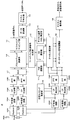
- FIG. 4 is a block diagram showing a configuration of mobile terminal apparatus 10 according to the present embodiment.
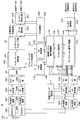
- FIG. 5 is a block diagram showing a configuration of radio base station apparatus 20 according to the present embodiment. Note that the configurations of the mobile terminal apparatus 10 and the radio base station apparatus 20 shown in FIG. 4 and FIG. 5 are simplified to explain the present invention, and the normal radio base station apparatus and the mobile terminal apparatus respectively have The configuration shall be provided.
- the transmission signal transmitted from the radio base station apparatus 20 is received by the reception antennas RX # 1 to RX # N and transmitted by the duplexers 101 # 1 to 101 # N. After being electrically separated into a path and a receiving path, the signals are output to the RF receiving circuits 102 # 1 to 102 # N. Then, the RF receiving circuits 102 # 1 to 102 # N perform frequency conversion processing for converting radio frequency signals into baseband signals.
- the baseband signal subjected to the frequency conversion processing is subjected to cyclic prefix (CP) removal units 103 # 1 to 103 # N after the CP is removed, and then to a fast Fourier transform unit (FFT unit) 104 # 1 to 104.
- CP cyclic prefix
- FFT unit fast Fourier transform unit
- Reception timing estimation section 105 estimates the reception timing from the reference signal included in the reception signal and notifies the estimation results to CP removal sections 103 # 1 to 103 # N.
- the FFT units 104 # 1 to 104 # N perform a Fourier transform on the input received signals, and convert the time series signals into frequency domain signals.
- the received signal converted into the frequency domain signal is output to data channel signal demodulation section 106.
- the data channel signal demodulator 106 uses, for example, the minimum mean square error (MMSE) or maximum likelihood estimation detection (MLD: Maximum Likelihood) for the received signals input from the FFT units 104 # 1 to 104 # N. Detection) Separation by signal separation method. As a result, the received signal arriving from the radio base station apparatus 20 is separated into received signals related to the users # 1 to #k, and the received signals related to the user of the mobile terminal apparatus 10 (here, user k) are extracted. The channel estimation unit 107 estimates the channel state from the reference signal included in the received signals output from the FFT units 104 # 1 to 104 # N, and the estimated channel state is compared with the data channel signal demodulation unit 106 and channel quality described later.
- MMSE minimum mean square error
- MLD Maximum Likelihood
- Data channel signal demodulating section 106 separates the received signal by the above-described MLD signal separation method based on the notified channel state. Thereby, the received signal regarding the user k is demodulated.
- the demodulation processing by the data channel signal demodulating unit 106 it is assumed that the extracted received signal regarding the user k is demapped by a subcarrier demapping unit (not shown) and returned to a time-series signal. .
- the received signal related to user k demodulated by data channel signal demodulation section 106 is output to channel decoding section 108. Then, the channel decoding unit 108 performs channel decoding processing to reproduce the transmission signal #k.
- the IQI measurement unit 109 measures the IQI using at least the channel state (channel estimation value) notified from the channel estimation unit 107 and the PMI selected by the PMI selection unit 111 described later. That is, IQI measurement section 109 obtains IQI by the above formula using at least the average transmission power of each radio base station apparatus and the quantization error on the mobile terminal apparatus side.
- the IQI of the connected cell and the IQI of the cooperative cell are calculated by the above formula (5) or formula (7).
- the IQI of the connected cell and the IQI of the cooperative cell are calculated by the above equation (9).
- the IQI of the connected cell and the IQI of the cooperative cell are calculated by the above equation (10).
- the IQI of the connected cell and the IQI of the cooperative cell are calculated by the above equation (11).
- the IQI measurement unit 109 uses at least the channel state and the PMI to perform IQI according to the above equations (5), (7), (9), (10), and (11).
- the second feedback method described above at least the channel state and the PMI are used to calculate the denominators of the above equations (5), (7), (9), (10), and (11).
- the value (IQI i, UE j ) is calculated.
- the IQI measurement unit 109 outputs the calculated IQI or IQI i, UE j to the feedback control signal generation unit 112.
- the IQI measurement part 109 carries out time average of IQI by said Formula (15) and Formula (16) as needed.
- the channel quality measurement unit 110 measures the channel quality (CQI) based on the channel state notified from the channel estimation unit 107. Then, the CQI that is the measurement result is output to the feedback control signal generation unit 110.
- the PMI selection unit 111 selects a PMI based on the channel state notified from the channel estimation unit 107. Then, the selected PMI is output to the feedback control signal generation unit 112.
- the feedback control signal generation unit 112 uses the IQI or IQI i, UE j from the IQI measurement unit 109, the CQI from the channel quality measurement unit 110, and the PMI from the PMI selection unit 111, and these are used as a radio base station apparatus.
- a control signal (eg, PUCCH) that feeds back to 20 is generated.
- the control signal generated by the feedback control signal generation unit 112 is output to the multiplexer (MUX) 117.
- Transmission data #k related to user #k sent from the higher layer is channel-encoded by channel encoder 113 and then data-modulated by data modulator 114.
- Transmission data #k data-modulated by data modulation section 114 is converted from a time-series signal to a frequency domain signal by a serial / parallel conversion section (not shown) and output to subcarrier mapping section 115.
- the subcarrier mapping unit 115 maps the transmission data #k to subcarriers according to the schedule information instructed from the radio base station apparatus 20. At this time, subcarrier mapping section 115 maps (multiplexes) reference signal #k generated by a reference signal generation section (not shown) to subcarriers together with transmission data #k. Transmission data #k mapped to subcarriers in this way is output to precoding multiplication section 116.
- the precoding multiplication unit 116 shifts the phase and / or amplitude of the transmission data #k for each of the reception antennas RX # 1 to RX # N based on the precoding weight obtained from the PMI selected by the PMI selection unit 111.
- the transmission data #k phase-shifted and / or amplitude-shifted by the precoding multiplier 116 is output to the multiplexer (MUX) 117.
- the multiplexer (MUX) 117 synthesizes the transmission data #k shifted in phase and / or amplitude and the control signal generated by the feedback control signal generation unit 112, and receives each of the reception antennas RX # 1 to RX # N. A transmission signal is generated.
- the transmission signal generated by the multiplexer (MUX) 117 is subjected to inverse fast Fourier transform by an inverse fast Fourier transform unit 118 # 1 to 118 # N, converted from a frequency domain signal to a time domain signal, and then subjected to CP addition.
- CPs are added by the units 119 # 1 to 119 # N and output to the RF transmission circuits 119 # 1 to 119 # N.
- the reception antennas RX # 1 to RX # are passed through the duplexers 101 # 1 to 101 # N. N is transmitted to the radio base station apparatus 20 via the uplink from the reception antennas RX # 1 to RX # N.
- a scheduler determines the number of users to be multiplexed (the number of multiplexed users) based on channel estimation values given from channel estimation sections 215 # 1 to 215 # k described later. . Then, uplink / downlink resource allocation contents (scheduling information) for each user are determined, and transmission data # 1 to #k for users # 1 to #k are transmitted to corresponding channel coding sections 201 # 1 to 201 # k. .
- Transmission data # 1 to #k are channel-encoded by channel encoders 201 # 1 to 201 # k, and then output to data modulators 202 # 1 to 202 # k for data modulation. At this time, channel coding and data modulation are performed based on channel coding rates and modulation schemes provided from CQI processing sections 220 # 1 to 220 # k described later. Transmission data # 1 to #k data-modulated by data modulators 202 # 1 to 202 # k are subjected to inverse Fourier transform by a discrete Fourier transform unit (not shown), and converted from a time-series signal to a frequency domain signal. It is output to the subcarrier mapping unit 203.
- the subcarrier mapping unit 203 maps the transmission data # 1 to #k to subcarriers according to the schedule information given from the scheduler. At this time, subcarrier mapping section 203 maps (multiplexes) reference signals # 1 to #k input from a reference signal generation section (not shown) to subcarriers together with transmission data # 1 to #k. Transmission data # 1 to #k mapped to subcarriers in this way are output to precoding multiplication sections 204 # 1 to 204 #k.
- Precoding multiplication sections 204 # 1 to 204 # k transmit transmission data # 1 to #k for each of transmission antennas TX # 1 to TX # N based on a precoding weight given from precoding weight generation section 221 to be described later. Phase and / or amplitude shift (weighting of transmit antenna TX # 1 to transmit antenna TX # N by precoding). Transmission data # 1 to #k whose phases and / or amplitudes are shifted by precoding multiplication sections 204 # 1 to 204 #k are output to multiplexer (MUX) 205.
- MUX multiplexer
- the transmission data # 1 to #k shifted in phase and / or amplitude are combined to generate transmission signals for the transmission antennas TX # 1 to TX # N.
- the transmission signal generated by the multiplexer (MUX) 205 is subjected to inverse fast Fourier transform by the inverse fast Fourier transform units 206 # 1 to 206 # N to be converted from a frequency domain signal to a time domain signal. Then, after the CP is added by the cyclic prefix (CP) adding units 207 # 1 to 207 # N, they are output to the RF transmission circuits 208 # 1 to 208 # N.
- CP cyclic prefix
- the transmission antennas TX # 1 to TX # are transmitted via the duplexers 209 # 1 to 209 # N.
- N is transmitted from the transmission antennas TX # 1 to TX # N to the mobile terminal apparatus 10 on the downlink.
- the transmission signal transmitted from the mobile terminal apparatus 10 in the uplink is received by the transmission antennas TX # 1 to TX # N, and is transmitted to the transmission path and the reception path by the duplexers 209 # 1 to 209 # N.
- the signals are output to the RF receiving circuits 210 # 1 to 210 # N.
- frequency conversion processing for converting the radio frequency signal into the baseband signal is performed in the RF receiving circuits 210 # 1 to 210 # N.
- the baseband signal subjected to the frequency conversion process is output to the fast Fourier transform units (FFT units) 212 # 1 to 212 # N after the CPs are removed by the CP removal units 211 # 1 to 211 # N. .
- FFT units fast Fourier transform units
- Reception timing estimation section 213 estimates the reception timing from the reference signal included in the reception signal, and notifies the CP removal sections 211 # 1 to 211 # N of the estimation result.
- the FFT units 212 # 1 to 212 # N perform Fourier transform on the input received signals, and convert the time series signals into frequency domain signals.
- the received signals converted into these frequency domain signals are output to data channel signal demultiplexing sections 214 # 1 to 214 # k.
- the data channel signal demultiplexing sections 214 # 1 to 214 # k use, for example, the minimum mean square error (MMSE) or maximum likelihood estimation of the received signals input from the FFT sections 212 # 1 to 212 # k. It separates by the detection (MLD: Maximum Likelihood Detection) signal separation method. As a result, the received signal that has arrived from the mobile terminal apparatus 10 is separated into received signals related to the users # 1 to #k.
- Channel estimation sections 215 # 1 to 215 # k estimate the channel state from the reference signal included in the received signals output from FFT sections 212 # 1 to 212 # k, and the estimated channel state is data channel signal separation section 214.
- Data channel signal separation sections 214 # 1 to 214 # k separate received signals by the MLD signal separation method described above based on the notified channel state.
- the received signals related to user # 1 to user #k separated by data channel signal separation sections 214 # 1 to 214 # k are demapped by a subcarrier demapping section (not shown) and returned to a time-series signal. Thereafter, the data is demodulated by a data demodulator (not shown).
- Channel decoding sections 217 # 1 to 217 # k perform channel decoding processing to reproduce transmission signals # 1 to #k.
- Control channel signal demodulation sections 216 # 1 to 216 # k demodulate control channel signals (for example, PDCCH) included in the reception signals input from FFT sections 212 # 1 to 212 # k. At this time, control channel signal demodulation sections 216 # 1 to 216 # k demodulate control channel signals corresponding to users # 1 to #k, respectively. At this time, control channel signal demodulation sections 216 # 1 to 216 # k demodulate the control channel signal based on the channel state notified from channel estimation sections 215 # 1 to 215 # k.
- control channel signal demodulation sections 216 # 1 to 216 # k demodulate the control channel signal based on the channel state notified from channel estimation sections 215 # 1 to 215 # k.
- control channel signals demodulated by the control channel signal demodulating units 216 # 1 to 216 # k are transmitted to the PMI processing units 218 # 1 to 218 # k, the IQI processing units 219 # 1 to 219 # k, and the CQI processing unit 220 #. 1 to 220 # k.
- the PMI processing units 218 # 1 to 218 # k extract PMI from information included in each control channel signal (for example, PUCCH) input from the control channel signal demodulation units 216 # 1 to 216 # k.
- the PMI reproduced by the PMI processing units 218 # 1 to 218 # k is output to the precoding weight generation unit 221.
- IQI processing sections 219 # 1 to 219 # k obtain IQI or IQI i, UE j from information included in each control channel signal (for example, PUCCH) input from control channel signal demodulation sections 216 # 1 to 216 # k. Extract. Also, IQI processing sections 219 # 1 to 219 # k output the extracted IQI to precoding weight generation section 221 in the first feedback method described above. In the second feedback method described above, the IQI processing units 219 # 1 to 219 # k receive information necessary for IQI measurement including at least a channel estimation value and PMI from the mobile terminal apparatus (UE) (the above equation (5), IQI is calculated
- the IQI processing units 219 # 1 to 219 # k use the extracted IQI i and UE j to perform the above equations (5), (7), (9), (10), and (11). IQI is calculated, and IQI is output to precoding weight generation section 221.
- the IQI processing units 219 # 1 to 219 # k calculate the IQI of the connected cell and the IQI of the cooperative cell by the above formula (5) or formula (7).
- the IQI of the connected cell and the IQI of the cooperative cell are calculated by the above equation (9).
- the IQI of the connected cell and the IQI of the cooperative cell are calculated by the above equation (10).
- the IQI processing units 219 # 1 to 219 # k average the IQI according to the above equations (15) and (16) as necessary.
- the CQI processing units 220 # 1 to 220 # k measure CQI from reference signals included in the control channel signals (for example, PUCCH) input from the control channel signal demodulation units 216 # 1 to 216 # k, and always Update the CQI information to the latest state.
- the CQI information updated to the CQI processing units 220 # 1 to 220 # k is output to the channel coding units 201 # 1 to 201 # k and the data modulation units 202 # 1 to 202 # k, respectively.
- Precoding weight generation section 221 uses transmission data # 1 to #k using PMI output from PMI processing sections 218 # 1 to 218 # k and IQI output from IQI processing sections 219 # 1 to 219 # k.
- a precoding weight indicating a phase shift amount and / or an amplitude shift amount is generated.
- Each generated precoding weight is output to precoding multiplication sections 204 # 1 to 204 # k, and is used for precoding transmission data # 1 to transmission data #k.
- the precoding weight generation unit 220 generates precoding weights as follows. First, as shown in the following equation (17), PMI is used as a channel coefficient (when it is assumed that there are three radio base station apparatuses in the cooperative cluster and two reception antennas on the mobile terminal side). Formula (17)
- the channel estimation unit 107 performs channel estimation using the downlink reference signal in the mobile terminal apparatus (UE). Then, PMI selection section 111 selects a PMI using the channel estimation value obtained by channel estimation section 107. Next, IQI measurement section 109 measures IQI using at least the channel estimation value and PMI. At this time, IQI measuring section 109 calculates IQI according to equations (5), (7), (9), (10), and (11) according to the first to third aspects. This IQI is fed back to the radio base station apparatus eNB.
- the precoding weight generation unit 221 In the radio base station apparatus eNB, the precoding weight generation unit 221 generates a precoding weight using the fed back PMI and IQI. At this time, the precoding weight generation unit 221 generates precoding weights according to the above equations (17) to (19). Next, the radio base station apparatus eNB performs cooperative multipoint transmission using MIMO transmission using the obtained precoding weight.
- the channel estimation unit 107 performs channel estimation using the downlink reference signal in the mobile terminal apparatus (UE). Then, PMI selection section 111 selects a PMI using the channel estimation value obtained by channel estimation section 107. Next, IQI measurement section 109 calculates IQI i, UE j using at least the channel estimation value and PMI. At this time, the IQI measurement unit 109 calculates IQI i, UE j according to Equation (5), Equation (7), Equation (9), Equation (10), and Equation (11) according to the first to third aspects. calculate. The IQI i and UE j are fed back to the radio base station apparatus eNB.
- the IQI processing unit 219 measures IQI using IQI i and UE j . At this time, the IQI processing unit 219 calculates the IQI according to the expressions (5), (7), (9), (10), and (11) according to the first to third aspects. Next, the precoding weight generation unit 221 generates a precoding weight using the fed back PMI and the calculated IQI. At this time, the precoding weight generation unit 221 generates precoding weights according to the above equations (17) to (19). Next, the radio base station apparatus eNB performs cooperative multipoint transmission using MIMO transmission using the obtained precoding weight.
Landscapes
- Engineering & Computer Science (AREA)
- Computer Networks & Wireless Communication (AREA)
- Signal Processing (AREA)
- Physics & Mathematics (AREA)
- Mathematical Physics (AREA)
- Mobile Radio Communication Systems (AREA)
- Radio Transmission System (AREA)
Priority Applications (2)
| Application Number | Priority Date | Filing Date | Title |
|---|---|---|---|
| US14/002,925 US9385794B2 (en) | 2011-03-04 | 2012-02-21 | Mobile terminal apparatus, radio base station apparatus and radio communication method |
| EP12754930.1A EP2683093B1 (de) | 2011-03-04 | 2012-02-21 | Mobiles endgerät, drahtlose basisstation und drahtloses kommunikationsverfahren |
Applications Claiming Priority (2)
| Application Number | Priority Date | Filing Date | Title |
|---|---|---|---|
| JP2011-047972 | 2011-03-04 | ||
| JP2011047972A JP5346970B2 (ja) | 2011-03-04 | 2011-03-04 | 移動端末装置、無線基地局装置及び無線通信方法 |
Publications (1)
| Publication Number | Publication Date |
|---|---|
| WO2012121008A1 true WO2012121008A1 (ja) | 2012-09-13 |
Family
ID=46797977
Family Applications (1)
| Application Number | Title | Priority Date | Filing Date |
|---|---|---|---|
| PCT/JP2012/054174 WO2012121008A1 (ja) | 2011-03-04 | 2012-02-21 | 移動端末装置、無線基地局装置及び無線通信方法 |
Country Status (4)
| Country | Link |
|---|---|
| US (1) | US9385794B2 (de) |
| EP (1) | EP2683093B1 (de) |
| JP (1) | JP5346970B2 (de) |
| WO (1) | WO2012121008A1 (de) |
Families Citing this family (10)
| Publication number | Priority date | Publication date | Assignee | Title |
|---|---|---|---|---|
| US9137818B2 (en) * | 2011-12-14 | 2015-09-15 | Alcatel Lucent | Method and system for a reduced-complexity scheduling for a network MIMO with linear zero-forcing beamforming |
| CN103580789B (zh) * | 2012-07-30 | 2018-08-10 | 中兴通讯股份有限公司 | 多点协作传输预编码处理方法、装置及系统 |
| KR102235686B1 (ko) | 2013-12-30 | 2021-04-06 | 한국전자통신연구원 | Mimo 기반 신호 간섭 제거 방법 |
| WO2016013351A1 (ja) * | 2014-07-25 | 2016-01-28 | 株式会社Nttドコモ | 基地局、ユーザ装置および無線通信ネットワーク |
| US10056926B2 (en) * | 2014-11-20 | 2018-08-21 | Lg Electronics Inc. | Method and device for transmitting and receiving inter-cell information for cancelling inter-cell interference |
| US10116601B2 (en) * | 2015-02-06 | 2018-10-30 | Jamdeo Canada Ltd. | Methods and devices for display device notifications |
| BR112019002672A2 (pt) | 2016-08-10 | 2019-05-14 | Idac Holdings, Inc. | método de transmissão de enlace ascendente implementado por uma unidade de transmissão/recepção sem fio, e, unidade de transmissão/recepção sem fio |
| US10609714B2 (en) | 2017-07-12 | 2020-03-31 | Qualcomm Incorporated | Spatial listen before talk |
| US11152994B1 (en) * | 2020-05-27 | 2021-10-19 | Apple Inc. | Communication of channel state information (CSI) in wireless networks |
| CN115529066A (zh) * | 2021-06-25 | 2022-12-27 | 华为技术有限公司 | 一种预编码权值计算方法以及相关装置 |
Citations (3)
| Publication number | Priority date | Publication date | Assignee | Title |
|---|---|---|---|---|
| JP2002238073A (ja) * | 2001-02-09 | 2002-08-23 | Ntt Docomo Inc | 呼受付制御装置及び基地局 |
| WO2010140298A1 (ja) * | 2009-06-02 | 2010-12-09 | パナソニック株式会社 | 無線通信装置及び無線通信方法 |
| JP2011035912A (ja) * | 2009-08-05 | 2011-02-17 | Ntt Docomo Inc | チャネル品質指示情報を取得する方法およびその基地局 |
Family Cites Families (12)
| Publication number | Priority date | Publication date | Assignee | Title |
|---|---|---|---|---|
| US8150412B2 (en) * | 2006-03-06 | 2012-04-03 | Alcatel Lucent | Interference mitigation in a wireless communication system |
| KR20080073196A (ko) * | 2007-02-05 | 2008-08-08 | 엘지전자 주식회사 | Mimo 시스템에서 효율적인 채널 품질 정보 전송 방법 |
| US8179775B2 (en) * | 2007-08-14 | 2012-05-15 | Texas Instruments Incorporated | Precoding matrix feedback processes, circuits and systems |
| US8463191B2 (en) * | 2009-04-02 | 2013-06-11 | Qualcomm Incorporated | Beamforming options with partial channel knowledge |
| US9350478B2 (en) * | 2009-04-24 | 2016-05-24 | Sharp Kabushiki Kaisha | Wireless communication system, wireless communication device, and wireless communication method |
| JP5205330B2 (ja) * | 2009-04-27 | 2013-06-05 | 株式会社日立製作所 | 無線通信システムおよび無線通信方法ならびに基地局装置 |
| US8219128B2 (en) * | 2009-06-12 | 2012-07-10 | Telefonaktiebolaget L M Ericsson (Publ) | Network-centric link adaptation for coordinated multipoint downlink transmission |
| CN102804896B (zh) * | 2009-06-18 | 2016-08-10 | 夏普株式会社 | 移动通信系统、基站装置、移动站装置和移动通信方法 |
| US8711716B2 (en) * | 2009-06-19 | 2014-04-29 | Texas Instruments Incorporated | Multiple CQI feedback for cellular networks |
| KR101590198B1 (ko) * | 2009-07-30 | 2016-02-15 | 엘지전자 주식회사 | 무선 통신 시스템에 있어서 다중 셀 협력 방법 |
| US8594688B2 (en) * | 2009-12-09 | 2013-11-26 | Qualcomm Incorporated | Method and system for rate prediction in coordinated multi-point transmission |
| US8675558B2 (en) * | 2011-01-07 | 2014-03-18 | Intel Corporation | CQI definition for transmission mode 9 in LTE-advanced |
-
2011
- 2011-03-04 JP JP2011047972A patent/JP5346970B2/ja not_active Expired - Fee Related
-
2012
- 2012-02-21 WO PCT/JP2012/054174 patent/WO2012121008A1/ja active Application Filing
- 2012-02-21 EP EP12754930.1A patent/EP2683093B1/de not_active Not-in-force
- 2012-02-21 US US14/002,925 patent/US9385794B2/en not_active Expired - Fee Related
Patent Citations (3)
| Publication number | Priority date | Publication date | Assignee | Title |
|---|---|---|---|---|
| JP2002238073A (ja) * | 2001-02-09 | 2002-08-23 | Ntt Docomo Inc | 呼受付制御装置及び基地局 |
| WO2010140298A1 (ja) * | 2009-06-02 | 2010-12-09 | パナソニック株式会社 | 無線通信装置及び無線通信方法 |
| JP2011035912A (ja) * | 2009-08-05 | 2011-02-17 | Ntt Docomo Inc | チャネル品質指示情報を取得する方法およびその基地局 |
Non-Patent Citations (3)
| Title |
|---|
| "Requirements for Evolved UTRA and Evolved UTRAN", 3GPP TR 25.913 |
| M. SADEK ET AL.: "A leakage-based precoding scheme for downlink multi-user MIMO channels", IEEE TRANS. WIRELESS COMMUN, vol. 6, no. 5, May 2007 (2007-05-01), pages 1713 |
| See also references of EP2683093A4 |
Also Published As
| Publication number | Publication date |
|---|---|
| US9385794B2 (en) | 2016-07-05 |
| EP2683093A4 (de) | 2014-08-27 |
| EP2683093A1 (de) | 2014-01-08 |
| EP2683093B1 (de) | 2015-10-14 |
| JP2012186631A (ja) | 2012-09-27 |
| US20140003272A1 (en) | 2014-01-02 |
| JP5346970B2 (ja) | 2013-11-20 |
Similar Documents
| Publication | Publication Date | Title |
|---|---|---|
| JP5296004B2 (ja) | フィードバック情報送信方法、移動局装置及び基地局装置 | |
| JP5346970B2 (ja) | 移動端末装置、無線基地局装置及び無線通信方法 | |
| US9124320B2 (en) | Mobile terminal apparatus, radio base station apparatus and radio communication method | |
| US9398590B2 (en) | Mobile terminal device and radio base station apparatus | |
| JP5388356B2 (ja) | プリコーディングウェイト生成方法、移動局装置及び基地局装置 | |
| JP5361933B2 (ja) | 移動端末装置、無線基地局装置、無線通信方法及び無線通信システム | |
| EP2750435B1 (de) | Drahtloses kommunikationssystem, rückmeldungsverfahren, benutzerendgerät und drahtlose basisstationsvorrichtung | |
| JP5291664B2 (ja) | データ送信方法、基地局装置及び移動局装置 | |
| US20130182787A1 (en) | Communication control method, base station apparatus and mobile station apparatus | |
| JP2014131201A (ja) | 無線基地局、ユーザ端末、無線通信方法、及び無線通信システム | |
| JP5268983B2 (ja) | 通信制御方法、移動局装置及び基地局装置 | |
| JP5396306B2 (ja) | プリコーディングウェイト生成方法及び制御装置 | |
| US8964870B2 (en) | Mobile station apparatus and channel information feedback method | |
| JP6523377B2 (ja) | ユーザ端末、無線基地局、及び無線通信方法 | |
| Nagata et al. | Interference measurement scheme for CoMP in LTE-advanced downlink | |
| WO2011155467A1 (ja) | 基地局間連携mimo伝送方法及び基地局装置 |
Legal Events
| Date | Code | Title | Description |
|---|---|---|---|
| 121 | Ep: the epo has been informed by wipo that ep was designated in this application |
Ref document number: 12754930 Country of ref document: EP Kind code of ref document: A1 |
|
| WWE | Wipo information: entry into national phase |
Ref document number: 14002925 Country of ref document: US |
|
| NENP | Non-entry into the national phase |
Ref country code: DE |
|
| WWE | Wipo information: entry into national phase |
Ref document number: 2012754930 Country of ref document: EP |