WO2012121008A1 - Mobile terminal device, wireless base station and wireless communication method - Google Patents
Mobile terminal device, wireless base station and wireless communication method Download PDFInfo
- Publication number
- WO2012121008A1 WO2012121008A1 PCT/JP2012/054174 JP2012054174W WO2012121008A1 WO 2012121008 A1 WO2012121008 A1 WO 2012121008A1 JP 2012054174 W JP2012054174 W JP 2012054174W WO 2012121008 A1 WO2012121008 A1 WO 2012121008A1
- Authority
- WO
- WIPO (PCT)
- Prior art keywords
- iqi
- mobile terminal
- base station
- pmi
- radio base
- Prior art date
Links
Images


Classifications
-
- H—ELECTRICITY
- H04—ELECTRIC COMMUNICATION TECHNIQUE
- H04B—TRANSMISSION
- H04B7/00—Radio transmission systems, i.e. using radiation field
- H04B7/02—Diversity systems; Multi-antenna system, i.e. transmission or reception using multiple antennas
- H04B7/04—Diversity systems; Multi-antenna system, i.e. transmission or reception using multiple antennas using two or more spaced independent antennas
- H04B7/0413—MIMO systems
- H04B7/0456—Selection of precoding matrices or codebooks, e.g. using matrices antenna weighting
-
- H—ELECTRICITY
- H04—ELECTRIC COMMUNICATION TECHNIQUE
- H04B—TRANSMISSION
- H04B7/00—Radio transmission systems, i.e. using radiation field
- H04B7/02—Diversity systems; Multi-antenna system, i.e. transmission or reception using multiple antennas
- H04B7/022—Site diversity; Macro-diversity
- H04B7/024—Co-operative use of antennas of several sites, e.g. in co-ordinated multipoint or co-operative multiple-input multiple-output [MIMO] systems
-
- H—ELECTRICITY
- H04—ELECTRIC COMMUNICATION TECHNIQUE
- H04B—TRANSMISSION
- H04B7/00—Radio transmission systems, i.e. using radiation field
- H04B7/02—Diversity systems; Multi-antenna system, i.e. transmission or reception using multiple antennas
- H04B7/04—Diversity systems; Multi-antenna system, i.e. transmission or reception using multiple antennas using two or more spaced independent antennas
- H04B7/06—Diversity systems; Multi-antenna system, i.e. transmission or reception using multiple antennas using two or more spaced independent antennas at the transmitting station
- H04B7/0613—Diversity systems; Multi-antenna system, i.e. transmission or reception using multiple antennas using two or more spaced independent antennas at the transmitting station using simultaneous transmission
- H04B7/0615—Diversity systems; Multi-antenna system, i.e. transmission or reception using multiple antennas using two or more spaced independent antennas at the transmitting station using simultaneous transmission of weighted versions of same signal
- H04B7/0619—Diversity systems; Multi-antenna system, i.e. transmission or reception using multiple antennas using two or more spaced independent antennas at the transmitting station using simultaneous transmission of weighted versions of same signal using feedback from receiving side
- H04B7/0636—Feedback format
- H04B7/0639—Using selective indices, e.g. of a codebook, e.g. pre-distortion matrix index [PMI] or for beam selection
-
- H—ELECTRICITY
- H04—ELECTRIC COMMUNICATION TECHNIQUE
- H04B—TRANSMISSION
- H04B7/00—Radio transmission systems, i.e. using radiation field
- H04B7/02—Diversity systems; Multi-antenna system, i.e. transmission or reception using multiple antennas
- H04B7/04—Diversity systems; Multi-antenna system, i.e. transmission or reception using multiple antennas using two or more spaced independent antennas
- H04B7/0413—MIMO systems
- H04B7/0417—Feedback systems
-
- H—ELECTRICITY
- H04—ELECTRIC COMMUNICATION TECHNIQUE
- H04B—TRANSMISSION
- H04B7/00—Radio transmission systems, i.e. using radiation field
- H04B7/02—Diversity systems; Multi-antenna system, i.e. transmission or reception using multiple antennas
- H04B7/04—Diversity systems; Multi-antenna system, i.e. transmission or reception using multiple antennas using two or more spaced independent antennas
- H04B7/06—Diversity systems; Multi-antenna system, i.e. transmission or reception using multiple antennas using two or more spaced independent antennas at the transmitting station
- H04B7/0613—Diversity systems; Multi-antenna system, i.e. transmission or reception using multiple antennas using two or more spaced independent antennas at the transmitting station using simultaneous transmission
- H04B7/0615—Diversity systems; Multi-antenna system, i.e. transmission or reception using multiple antennas using two or more spaced independent antennas at the transmitting station using simultaneous transmission of weighted versions of same signal
- H04B7/0619—Diversity systems; Multi-antenna system, i.e. transmission or reception using multiple antennas using two or more spaced independent antennas at the transmitting station using simultaneous transmission of weighted versions of same signal using feedback from receiving side
- H04B7/0621—Feedback content
- H04B7/0632—Channel quality parameters, e.g. channel quality indicator [CQI]
-
- H—ELECTRICITY
- H04—ELECTRIC COMMUNICATION TECHNIQUE
- H04B—TRANSMISSION
- H04B7/00—Radio transmission systems, i.e. using radiation field
- H04B7/02—Diversity systems; Multi-antenna system, i.e. transmission or reception using multiple antennas
- H04B7/04—Diversity systems; Multi-antenna system, i.e. transmission or reception using multiple antennas using two or more spaced independent antennas
- H04B7/06—Diversity systems; Multi-antenna system, i.e. transmission or reception using multiple antennas using two or more spaced independent antennas at the transmitting station
- H04B7/0686—Hybrid systems, i.e. switching and simultaneous transmission
- H04B7/0695—Hybrid systems, i.e. switching and simultaneous transmission using beam selection
-
- H—ELECTRICITY
- H04—ELECTRIC COMMUNICATION TECHNIQUE
- H04J—MULTIPLEX COMMUNICATION
- H04J11/00—Orthogonal multiplex systems, e.g. using WALSH codes
- H04J11/0023—Interference mitigation or co-ordination
- H04J11/0026—Interference mitigation or co-ordination of multi-user interference
- H04J11/003—Interference mitigation or co-ordination of multi-user interference at the transmitter
- H04J11/0033—Interference mitigation or co-ordination of multi-user interference at the transmitter by pre-cancellation of known interference, e.g. using a matched filter, dirty paper coder or Thomlinson-Harashima precoder
-
- H—ELECTRICITY
- H04—ELECTRIC COMMUNICATION TECHNIQUE
- H04J—MULTIPLEX COMMUNICATION
- H04J11/00—Orthogonal multiplex systems, e.g. using WALSH codes
- H04J11/0023—Interference mitigation or co-ordination
- H04J11/005—Interference mitigation or co-ordination of intercell interference
- H04J11/0053—Interference mitigation or co-ordination of intercell interference using co-ordinated multipoint transmission/reception
-
- H—ELECTRICITY
- H04—ELECTRIC COMMUNICATION TECHNIQUE
- H04J—MULTIPLEX COMMUNICATION
- H04J2211/00—Orthogonal indexing scheme relating to orthogonal multiplex systems
- H04J2211/003—Orthogonal indexing scheme relating to orthogonal multiplex systems within particular systems or standards
- H04J2211/005—Long term evolution [LTE]
-
- H—ELECTRICITY
- H04—ELECTRIC COMMUNICATION TECHNIQUE
- H04L—TRANSMISSION OF DIGITAL INFORMATION, e.g. TELEGRAPHIC COMMUNICATION
- H04L25/00—Baseband systems
- H04L25/02—Details ; arrangements for supplying electrical power along data transmission lines
- H04L25/03—Shaping networks in transmitter or receiver, e.g. adaptive shaping networks
- H04L25/03891—Spatial equalizers
- H04L25/03949—Spatial equalizers equalizer selection or adaptation based on feedback
Definitions
- the present invention relates to a mobile terminal apparatus, a radio base station apparatus, and a radio communication method, and more particularly to a mobile terminal apparatus, a radio base station apparatus, and a radio communication method that support multi-antenna transmission.
- UMTS Universal Mobile Telecommunications System
- WSDPA High Speed Downlink Packet Access
- HSUPA High Speed Uplink Packet Access
- CDMA Wideband Code Division Multiple Access
- the third generation system can achieve a maximum transmission rate of about 2 Mbps on the downlink using generally a fixed bandwidth of 5 MHz.
- a maximum transmission rate of about 300 Mbps on the downlink and about 75 Mbps on the uplink can be realized using a variable band of 1.4 MHz to 20 MHz.
- LTE-A LTE Advanced
- LTE-A LTE Advanced
- a MIMO (Multi Input Multi Output) system has been proposed as a wireless communication technology that improves data rate (frequency utilization efficiency) by transmitting and receiving data with a plurality of antennas (for example, non-patented).
- Reference 1 a MIMO system, a plurality of transmission / reception antennas are prepared in a transmitter / receiver, and different transmission information sequences are transmitted simultaneously from different transmission antennas.
- the data rate frequency utilization efficiency
- the data rate is increased by separating and detecting simultaneously transmitted information sequences using the fact that different fading fluctuations occur between transmission / reception antennas. Is possible.
- transmission information sequences transmitted simultaneously from different transmission antennas are all transmitted from a single user MIMO (SU-MIMO (Single User MIMO)), which is for the same user, and multi-users, which are for different users.
- SU-MIMO Single User MIMO
- MU-MIMO Multiple User MIMO
- the phase / amplitude control amount (precoding matrix (precoding weight)) to be set in the antenna of the transmitter on the receiver side is associated with this precoding matrix.
- An optimum PMI is selected from a code book in which a plurality of PMIs (Precoding Matrix Indicators) are determined, and this is fed back to the transmitter.
- precoding is performed for each transmission antenna and a transmission information sequence is transmitted.
- Typical precoding methods include ZF (Zero Forcing), BD (Block Diagonalization) ZF, MMSE (Minimum Mean Square Error), SLNR (Signal to Leakage plus Noise Ratio), and the like.
- SLNR precoding the power of a desired signal received at a receiver (for example, a mobile terminal device) is changed from interference, noise, and total power due to signal “leakage” at other mobile terminal devices in a cooperative cluster. Maximize the value divided by the sum of and.
- SINR Signal to Interference plus Noise Ratio
- Inter-cell orthogonalization is one of the promising technologies for further improving system performance over the Rel-8 LTE system.
- LTE-A system LTE-A system
- orthogonalization within a cell is realized by orthogonal multi-access for both uplink and downlink. That is, in the downlink, orthogonalization is performed between mobile terminal devices (User Equipment) in the frequency domain.
- W-CDMA mobile terminal devices
- inter-cell randomization of interference by 1-cell frequency repetition is fundamental.
- 3GPP (3rd Generation Partnership Project) cooperative multipoint transmission / reception
- CoMP cooperative multipoint transmission / reception
- a plurality of cells perform transmission / reception signal processing in cooperation with one or a plurality of mobile terminal apparatuses (UEs).
- UEs mobile terminal apparatuses
- simultaneous transmission of multiple cells to which precoding is applied, coordinated scheduling / beamforming, and the like are being studied.
- the transmission power component in the numerator of the above formula (1) is not a value averaged in the time direction but an instantaneous value.
- the instantaneous CQI used as the average received SINR does not take into account quantization error (deviation from the desired beam direction). For this reason, if SLNR precoding is performed using the instantaneous CQI as the average received SINR, an accurate precoding weight cannot be generated.
- the present invention has been made in view of such points, and provides a mobile terminal device, a radio base station device, and a radio communication method capable of generating an accurate precoding weight in cooperative multipoint transmission (CoMP). With the goal.
- CoMP cooperative multipoint transmission
- the mobile terminal apparatus of the present invention includes a channel estimation unit that performs channel estimation using a downlink reference signal, a PMI selection unit that selects a PMI using a channel estimation value obtained by the channel estimation unit, and at least the channel estimation An IQI measurement unit that measures an IQI (Interference Quality Indicator) using the value and the PMI, and a transmission unit that transmits at least the PMI and the IQI to a radio base station apparatus.
- IQI Interference Quality Indicator
- the radio base station apparatus of the present invention uses a precoding weight generation unit that generates a precoding weight using PMI and IQI fed back from a mobile terminal apparatus, and a cooperative multi-track using MIMO transmission using the precoding weight. And a transmitter for transmitting points.
- the radio communication method includes a step of channel estimation using a downlink reference signal, a step of selecting a PMI using an obtained channel estimation value, and at least the channel estimation value and the PMI in a mobile terminal device.
- a step of measuring IQI using a radio frequency a step of transmitting at least the PMI and the IQI to a radio base station device, and a step of generating a precoding weight using the PMI and the IQI in the radio base station device, And cooperative multipoint transmission using MIMO transmission using the precoding weight.
- IQI may be exchanged between radio base stations in a cooperative cluster (in a CoMP set) in order to calculate SLNR precoding.
- the mobile terminal apparatus measures IQI using at least the channel estimation value and the PMI, the radio base station apparatus generates precoding weight using the PMI and IQI, and MIMO transmission using the precoding weight
- the IQI taking into account the average transmission power from each radio base station and the instantaneous quantization error in the mobile terminal apparatus is used as the average reception SINR. Accurate SLNR precoding can be performed.
- Downlink CoMP transmission includes Coordinated Scheduling / Coordinated Beamforming (CS / CB) and Joint processing.
- Coordinated scheduling / Coordinated beamforming is a method of transmitting from one cell only to one UE as shown in FIG. 1, and taking into account interference from other cells and interference to other cells, radio resources in the frequency / space region It is a method of assigning.
- Joint processing is simultaneous transmission of multiple cells to which precoding is applied, and includes Joint transmission that is transmitted from multiple cells to one UE and Dynamic Cell Selection that instantaneously selects a cell.
- the mobile terminal apparatus UE measures the channel coefficient using the received signal from each antenna, and based on the measured channel coefficient, the radio base station apparatus eNB PMI and RI (Rank Indicator) corresponding to the phase / amplitude control amount (precoding weight) that maximizes the throughput after combining the transmission data from the transmission antennas are selected from the precoding codebook. Then, the selected PMI and RI are fed back to the radio base station apparatus eNB in the uplink together with the channel quality information CQI.
- PMI and RI Rank Indicator
- precoding weight precoding weight
- the radio base station apparatus eNB performs channel coding and data modulation (AMC: Adaptive Modulation and Coding) on the transmission signal, and precodes transmission data based on PMI and RI fed back from the mobile terminal apparatus (UE). .
- AMC Adaptive Modulation and Coding
- the phase and amplitude are controlled (shifted) for each transmission antenna. Thereafter, the transmission data shifted in phase and amplitude is transmitted from each antenna.
- the transmission power component in the numerator of the above formula (1) is not an average but instantaneous.
- the instantaneous CQI does not consider the quantization error, an accurate precoding weight cannot be generated.
- the present inventors define new feedback information that includes an average transmission power component and corrects a quantization error, and generates an accurate precoding weight by performing SLNR precoding using this feedback information. It has been found that it can be done, and has led to the present invention.
- the gist of the present invention is to measure IQI using at least a channel estimation value and PMI, generate a precoding weight using PMI and IQI, and use coordinated multipoint using MIMO transmission using the precoding weight.
- accurate SLNR precoding is performed using IQI taking into account the average transmission power from each radio base station and the quantization error on the mobile terminal device side.
- an interference quality index (IQI: Interference Quality Indicator) is newly defined during SLNR precoding. Therefore, in the present invention, in downlink coordinated multipoint transmission, IQI is fed back from the mobile terminal apparatus to the radio base station apparatus as feedback information in addition to PMI and CQI.
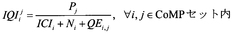
- IQI is calculated as the following formula (3).
- the received signal y i in the mobile terminal apparatus is calculated from the desired signal component and the interference signal component including quantization error and noise as shown in the following equation (4).
- P j Average transmission power of radio base station apparatus j QE i, j : Quantization error of channel between radio base station apparatus j and mobile terminal apparatus i in mobile terminal apparatus i
- ICI i CoMP in mobile terminal apparatus i
- Interference excluding interference from cells belonging to the set N i Average noise equation (4) at the receiver of the mobile terminal device i H i j : downlink channel state
- F i j PMI feedback from mobile terminal apparatus i
- specific feedback information IQI is defined in five modes.
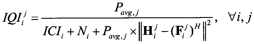
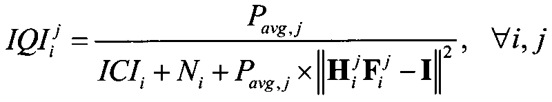
- IQI is defined by the following formula (5).
- P avg, j Average total transmission power of radio base station apparatus j
- the numerator P avg, j indicates the average transmission power
- ICI i + N i indicates interference + average noise from other cells (cells other than the CoMP set) on the mobile terminal device side
- P avg , j ⁇ ⁇ H i j ⁇ (F i j ) H ⁇ 2 represents a quantization error.
- IQI is a parameter that takes both into account. Since the radio base station apparatus performs SLNR precoding using this IQI, an accurate precoding weight can be generated.
- IQI is not limited to the above formulas (5) and (7), and can be applied to all substantially equivalent formulas by formula transformation or the like.
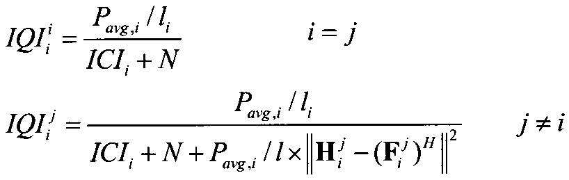
- IQI is defined by the following formula (9).
- the IQI for the connected cell (serving cell) (eNB 1 in FIG. 1) and the IQI for the cooperative cell (eNB 2 in FIG. 1) are defined separately. That is, in the IQI calculation, the connection cell is regarded as having a small quantization error and is not considered in the IQ calculation formula of the connection cell, but the quantization error is considered only for the cooperative cell.
- Formula (9) The description of the same parameters as in the above formula is the same as in the above formula and will be omitted.
- IQI is a parameter that takes both into account. Since the radio base station apparatus performs SLNR precoding using this IQI, an accurate precoding weight can be generated. In this case, since the quantization error is not considered for the connected cells, the IQI calculation amount can be reduced.
- the definition of IQI is not limited to the above formula (9), but can be applied to all substantially equivalent formulas by formula conversion or the like.
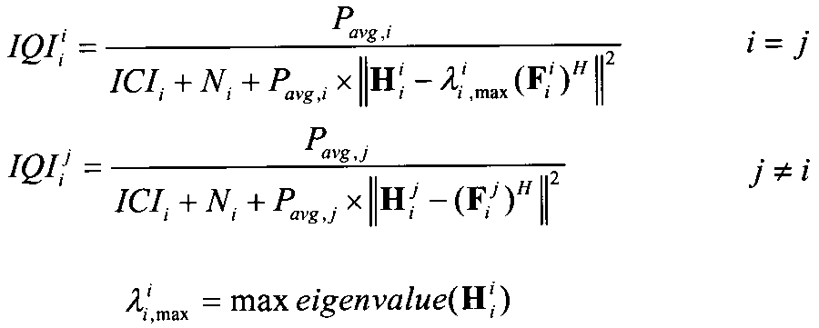
- IQI is defined by the following formula (10). Also in this aspect, the IQI for the connected cell (serving cell) (eNB 1 in FIG. 1) and the IQI for the cooperative cell (eNB 2 in FIG. 1) are defined separately. That is, in calculating IQI, when considering the quantization error, the quantization error is small for the connected cell, so the weight of the quantization error is reduced. Specifically, for the connected cell, the maximum eigenvalue obtained by eigendecomposition of the channel matrix H i i is used. Formula (10) The description of the same parameters as in the above formula is the same as in the above formula and will be omitted.
- IQI is a parameter considering both. Since the radio base station apparatus performs SLNR precoding using this IQI, an accurate precoding weight can be generated. In this case, for the connected cell and the cooperative cell, the quantization error is calculated by changing the weight, so that the quantization error can be calculated more accurately.
- the definition of IQI is not limited to the above formula (10), but can be applied to all substantially equivalent formulas by formula conversion or the like.
- the mobile terminal apparatus may calculate the IQI using the downlink reference signal, and the mobile terminal apparatus may transmit the calculated IQI to the radio base station apparatus in the uplink (first feedback method).
- a part of values required for the IQI calculation in the mobile terminal device (values that can be calculated only in the mobile terminal device) (the above formula (5), the above formula (7), the above formula (9), the above formula ( 10), the calculated value of the denominator in the above equation (11): IQI i, UE j )
- the mobile terminal device transmits the calculated value to the radio base station device in the uplink, and the radio base station device IQI may be calculated using the calculated value (second feedback method).
- the radio base station device IQI may be calculated using the calculated value (second feedback method).
- the calculated values IQI i and UE j fed back by the mobile terminal apparatus are values shown in the following formula (13).
- the calculated values IQI i and UE j are transmitted to the radio base station apparatus.
- the average total transmission power (P avg, j ) of the radio base station apparatus j is known (for example, by exchanging information between radio base stations in the cluster).
- the calculated values IQI i and UE j fed back by the mobile terminal apparatus are values calculated using the denominator of the above equation (9).
- This calculated value IQI i, UE j (connected cell and cooperative cell) is transmitted to the radio base station apparatus.
- the calculated values IQI i and UE j fed back by the mobile terminal apparatus are values calculated by the denominator of the above equation (8).
- This calculated value IQI i, UE j (connected cell and cooperative cell) is transmitted to the radio base station apparatus.
- instantaneous values are used in the IQI calculation considering the quantization error.
- the IQI time averaging may be performed on the mobile terminal device side or on the radio base station device side. That is, the mobile terminal apparatus obtains an IQI instantaneous value, feeds back this IQI instantaneous value to the radio base station apparatus, and the radio base station apparatus performs time averaging of IQI as shown in the above equation (15). May be.
- the IQI time average interval is longer than the CQI time average interval.
- the IQI instantaneous value at time T + 1 and the IQI average value at time T may be weighted and averaged.
- the weighting of the IQI instantaneous value at time T + 1 is increased, and when the weighting of the average value is increased compared to the instantaneous value, The IQI average value weight at time T is increased.
- the value of (alpha) can be changed and the weighting with respect to an instantaneous value and an average value can be adjusted.
- IQI calculation accuracy can be improved by time averaging IQI, and the accuracy of the SLNR precoding weight can be improved.
- FIG. 3 is a diagram for explaining a configuration of the mobile communication system 1 including the mobile terminal apparatus 10 and the radio base station apparatus 20 according to the embodiment of the present invention.
- the mobile communication system 1 shown in FIG. 3 is a system including, for example, an LTE system or SUPER 3G.
- the mobile communication system 1 may be called IMT-Advanced or 4G.
- the mobile communication system 1 includes a radio base station apparatus 20 and a plurality of mobile terminal apparatuses 10 (10 1 , 10 2 , 10 3 ,... 10 n that communicate with the radio base station apparatus 20.
- N is an integer of n> 0).
- the radio base station apparatus 20 is connected to the higher station apparatus 30, and the higher station apparatus 30 is connected to the core network 40.
- the mobile terminal apparatus 10 communicates with the radio base station apparatus 20 in the cell 50.
- the upper station device 30 includes, for example, an access gateway device, a radio network controller (RNC), a mobility management entity (MME), and the like, but is not limited thereto.
- RNC radio network controller
- MME mobility management entity
- each mobile terminal apparatus (10 1 , 10 2 , 10 3 ,... 10 n ) has the same configuration, function, and state, the following description will be given as the mobile terminal apparatus 10 unless otherwise specified. Proceed. For convenience of explanation, it is assumed that the mobile terminal device 10 is in radio communication with the radio base station device 20, but more generally a user device (UE) including both the mobile terminal device and the fixed terminal device may be used. .
- UE user device
- OFDMA Orthogonal Frequency Division Multiple Access
- SC-FDMA Single Carrier Frequency Division Multiple Access
- OFDMA is a multi-carrier transmission scheme that performs communication by dividing a frequency band into a plurality of narrow frequency bands (subcarriers) and mapping data to each subcarrier.
- SC-FDMA is a single carrier transmission method that reduces interference between terminals by dividing a system band into bands each consisting of one or continuous resource blocks for each terminal, and a plurality of terminals using different bands. .
- PDSCH shared by each mobile terminal apparatus 10 and downlink L1 / L2 control channels (PDCCH, PCFICH, PHICH) are used.
- User data that is, a normal data signal is transmitted by this PDSCH. Transmission data is included in this user data.
- the CC and scheduling information assigned to the mobile terminal apparatus 10 by the radio base station apparatus 20 are notified to the mobile terminal apparatus 10 through the L1 / L2 control channel.
- PUSCH Physical Uplink Shared Channel
- PUCCH Physical Uplink Control Channel
- User data is transmitted by this PUSCH.
- downlink radio quality information CQI: Channel Quality Indicator
- CQI Channel Quality Indicator
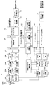
- FIG. 4 is a block diagram showing a configuration of mobile terminal apparatus 10 according to the present embodiment.
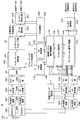
- FIG. 5 is a block diagram showing a configuration of radio base station apparatus 20 according to the present embodiment. Note that the configurations of the mobile terminal apparatus 10 and the radio base station apparatus 20 shown in FIG. 4 and FIG. 5 are simplified to explain the present invention, and the normal radio base station apparatus and the mobile terminal apparatus respectively have The configuration shall be provided.
- the transmission signal transmitted from the radio base station apparatus 20 is received by the reception antennas RX # 1 to RX # N and transmitted by the duplexers 101 # 1 to 101 # N. After being electrically separated into a path and a receiving path, the signals are output to the RF receiving circuits 102 # 1 to 102 # N. Then, the RF receiving circuits 102 # 1 to 102 # N perform frequency conversion processing for converting radio frequency signals into baseband signals.
- the baseband signal subjected to the frequency conversion processing is subjected to cyclic prefix (CP) removal units 103 # 1 to 103 # N after the CP is removed, and then to a fast Fourier transform unit (FFT unit) 104 # 1 to 104.
- CP cyclic prefix
- FFT unit fast Fourier transform unit
- Reception timing estimation section 105 estimates the reception timing from the reference signal included in the reception signal and notifies the estimation results to CP removal sections 103 # 1 to 103 # N.
- the FFT units 104 # 1 to 104 # N perform a Fourier transform on the input received signals, and convert the time series signals into frequency domain signals.
- the received signal converted into the frequency domain signal is output to data channel signal demodulation section 106.
- the data channel signal demodulator 106 uses, for example, the minimum mean square error (MMSE) or maximum likelihood estimation detection (MLD: Maximum Likelihood) for the received signals input from the FFT units 104 # 1 to 104 # N. Detection) Separation by signal separation method. As a result, the received signal arriving from the radio base station apparatus 20 is separated into received signals related to the users # 1 to #k, and the received signals related to the user of the mobile terminal apparatus 10 (here, user k) are extracted. The channel estimation unit 107 estimates the channel state from the reference signal included in the received signals output from the FFT units 104 # 1 to 104 # N, and the estimated channel state is compared with the data channel signal demodulation unit 106 and channel quality described later.
- MMSE minimum mean square error
- MLD Maximum Likelihood
- Data channel signal demodulating section 106 separates the received signal by the above-described MLD signal separation method based on the notified channel state. Thereby, the received signal regarding the user k is demodulated.
- the demodulation processing by the data channel signal demodulating unit 106 it is assumed that the extracted received signal regarding the user k is demapped by a subcarrier demapping unit (not shown) and returned to a time-series signal. .
- the received signal related to user k demodulated by data channel signal demodulation section 106 is output to channel decoding section 108. Then, the channel decoding unit 108 performs channel decoding processing to reproduce the transmission signal #k.
- the IQI measurement unit 109 measures the IQI using at least the channel state (channel estimation value) notified from the channel estimation unit 107 and the PMI selected by the PMI selection unit 111 described later. That is, IQI measurement section 109 obtains IQI by the above formula using at least the average transmission power of each radio base station apparatus and the quantization error on the mobile terminal apparatus side.
- the IQI of the connected cell and the IQI of the cooperative cell are calculated by the above formula (5) or formula (7).
- the IQI of the connected cell and the IQI of the cooperative cell are calculated by the above equation (9).
- the IQI of the connected cell and the IQI of the cooperative cell are calculated by the above equation (10).
- the IQI of the connected cell and the IQI of the cooperative cell are calculated by the above equation (11).
- the IQI measurement unit 109 uses at least the channel state and the PMI to perform IQI according to the above equations (5), (7), (9), (10), and (11).
- the second feedback method described above at least the channel state and the PMI are used to calculate the denominators of the above equations (5), (7), (9), (10), and (11).
- the value (IQI i, UE j ) is calculated.
- the IQI measurement unit 109 outputs the calculated IQI or IQI i, UE j to the feedback control signal generation unit 112.
- the IQI measurement part 109 carries out time average of IQI by said Formula (15) and Formula (16) as needed.
- the channel quality measurement unit 110 measures the channel quality (CQI) based on the channel state notified from the channel estimation unit 107. Then, the CQI that is the measurement result is output to the feedback control signal generation unit 110.
- the PMI selection unit 111 selects a PMI based on the channel state notified from the channel estimation unit 107. Then, the selected PMI is output to the feedback control signal generation unit 112.
- the feedback control signal generation unit 112 uses the IQI or IQI i, UE j from the IQI measurement unit 109, the CQI from the channel quality measurement unit 110, and the PMI from the PMI selection unit 111, and these are used as a radio base station apparatus.
- a control signal (eg, PUCCH) that feeds back to 20 is generated.
- the control signal generated by the feedback control signal generation unit 112 is output to the multiplexer (MUX) 117.
- Transmission data #k related to user #k sent from the higher layer is channel-encoded by channel encoder 113 and then data-modulated by data modulator 114.
- Transmission data #k data-modulated by data modulation section 114 is converted from a time-series signal to a frequency domain signal by a serial / parallel conversion section (not shown) and output to subcarrier mapping section 115.
- the subcarrier mapping unit 115 maps the transmission data #k to subcarriers according to the schedule information instructed from the radio base station apparatus 20. At this time, subcarrier mapping section 115 maps (multiplexes) reference signal #k generated by a reference signal generation section (not shown) to subcarriers together with transmission data #k. Transmission data #k mapped to subcarriers in this way is output to precoding multiplication section 116.
- the precoding multiplication unit 116 shifts the phase and / or amplitude of the transmission data #k for each of the reception antennas RX # 1 to RX # N based on the precoding weight obtained from the PMI selected by the PMI selection unit 111.
- the transmission data #k phase-shifted and / or amplitude-shifted by the precoding multiplier 116 is output to the multiplexer (MUX) 117.
- the multiplexer (MUX) 117 synthesizes the transmission data #k shifted in phase and / or amplitude and the control signal generated by the feedback control signal generation unit 112, and receives each of the reception antennas RX # 1 to RX # N. A transmission signal is generated.
- the transmission signal generated by the multiplexer (MUX) 117 is subjected to inverse fast Fourier transform by an inverse fast Fourier transform unit 118 # 1 to 118 # N, converted from a frequency domain signal to a time domain signal, and then subjected to CP addition.
- CPs are added by the units 119 # 1 to 119 # N and output to the RF transmission circuits 119 # 1 to 119 # N.
- the reception antennas RX # 1 to RX # are passed through the duplexers 101 # 1 to 101 # N. N is transmitted to the radio base station apparatus 20 via the uplink from the reception antennas RX # 1 to RX # N.
- a scheduler determines the number of users to be multiplexed (the number of multiplexed users) based on channel estimation values given from channel estimation sections 215 # 1 to 215 # k described later. . Then, uplink / downlink resource allocation contents (scheduling information) for each user are determined, and transmission data # 1 to #k for users # 1 to #k are transmitted to corresponding channel coding sections 201 # 1 to 201 # k. .
- Transmission data # 1 to #k are channel-encoded by channel encoders 201 # 1 to 201 # k, and then output to data modulators 202 # 1 to 202 # k for data modulation. At this time, channel coding and data modulation are performed based on channel coding rates and modulation schemes provided from CQI processing sections 220 # 1 to 220 # k described later. Transmission data # 1 to #k data-modulated by data modulators 202 # 1 to 202 # k are subjected to inverse Fourier transform by a discrete Fourier transform unit (not shown), and converted from a time-series signal to a frequency domain signal. It is output to the subcarrier mapping unit 203.
- the subcarrier mapping unit 203 maps the transmission data # 1 to #k to subcarriers according to the schedule information given from the scheduler. At this time, subcarrier mapping section 203 maps (multiplexes) reference signals # 1 to #k input from a reference signal generation section (not shown) to subcarriers together with transmission data # 1 to #k. Transmission data # 1 to #k mapped to subcarriers in this way are output to precoding multiplication sections 204 # 1 to 204 #k.
- Precoding multiplication sections 204 # 1 to 204 # k transmit transmission data # 1 to #k for each of transmission antennas TX # 1 to TX # N based on a precoding weight given from precoding weight generation section 221 to be described later. Phase and / or amplitude shift (weighting of transmit antenna TX # 1 to transmit antenna TX # N by precoding). Transmission data # 1 to #k whose phases and / or amplitudes are shifted by precoding multiplication sections 204 # 1 to 204 #k are output to multiplexer (MUX) 205.
- MUX multiplexer
- the transmission data # 1 to #k shifted in phase and / or amplitude are combined to generate transmission signals for the transmission antennas TX # 1 to TX # N.
- the transmission signal generated by the multiplexer (MUX) 205 is subjected to inverse fast Fourier transform by the inverse fast Fourier transform units 206 # 1 to 206 # N to be converted from a frequency domain signal to a time domain signal. Then, after the CP is added by the cyclic prefix (CP) adding units 207 # 1 to 207 # N, they are output to the RF transmission circuits 208 # 1 to 208 # N.
- CP cyclic prefix
- the transmission antennas TX # 1 to TX # are transmitted via the duplexers 209 # 1 to 209 # N.
- N is transmitted from the transmission antennas TX # 1 to TX # N to the mobile terminal apparatus 10 on the downlink.
- the transmission signal transmitted from the mobile terminal apparatus 10 in the uplink is received by the transmission antennas TX # 1 to TX # N, and is transmitted to the transmission path and the reception path by the duplexers 209 # 1 to 209 # N.
- the signals are output to the RF receiving circuits 210 # 1 to 210 # N.
- frequency conversion processing for converting the radio frequency signal into the baseband signal is performed in the RF receiving circuits 210 # 1 to 210 # N.
- the baseband signal subjected to the frequency conversion process is output to the fast Fourier transform units (FFT units) 212 # 1 to 212 # N after the CPs are removed by the CP removal units 211 # 1 to 211 # N. .
- FFT units fast Fourier transform units
- Reception timing estimation section 213 estimates the reception timing from the reference signal included in the reception signal, and notifies the CP removal sections 211 # 1 to 211 # N of the estimation result.
- the FFT units 212 # 1 to 212 # N perform Fourier transform on the input received signals, and convert the time series signals into frequency domain signals.
- the received signals converted into these frequency domain signals are output to data channel signal demultiplexing sections 214 # 1 to 214 # k.
- the data channel signal demultiplexing sections 214 # 1 to 214 # k use, for example, the minimum mean square error (MMSE) or maximum likelihood estimation of the received signals input from the FFT sections 212 # 1 to 212 # k. It separates by the detection (MLD: Maximum Likelihood Detection) signal separation method. As a result, the received signal that has arrived from the mobile terminal apparatus 10 is separated into received signals related to the users # 1 to #k.
- Channel estimation sections 215 # 1 to 215 # k estimate the channel state from the reference signal included in the received signals output from FFT sections 212 # 1 to 212 # k, and the estimated channel state is data channel signal separation section 214.
- Data channel signal separation sections 214 # 1 to 214 # k separate received signals by the MLD signal separation method described above based on the notified channel state.
- the received signals related to user # 1 to user #k separated by data channel signal separation sections 214 # 1 to 214 # k are demapped by a subcarrier demapping section (not shown) and returned to a time-series signal. Thereafter, the data is demodulated by a data demodulator (not shown).
- Channel decoding sections 217 # 1 to 217 # k perform channel decoding processing to reproduce transmission signals # 1 to #k.
- Control channel signal demodulation sections 216 # 1 to 216 # k demodulate control channel signals (for example, PDCCH) included in the reception signals input from FFT sections 212 # 1 to 212 # k. At this time, control channel signal demodulation sections 216 # 1 to 216 # k demodulate control channel signals corresponding to users # 1 to #k, respectively. At this time, control channel signal demodulation sections 216 # 1 to 216 # k demodulate the control channel signal based on the channel state notified from channel estimation sections 215 # 1 to 215 # k.
- control channel signal demodulation sections 216 # 1 to 216 # k demodulate the control channel signal based on the channel state notified from channel estimation sections 215 # 1 to 215 # k.
- control channel signals demodulated by the control channel signal demodulating units 216 # 1 to 216 # k are transmitted to the PMI processing units 218 # 1 to 218 # k, the IQI processing units 219 # 1 to 219 # k, and the CQI processing unit 220 #. 1 to 220 # k.
- the PMI processing units 218 # 1 to 218 # k extract PMI from information included in each control channel signal (for example, PUCCH) input from the control channel signal demodulation units 216 # 1 to 216 # k.
- the PMI reproduced by the PMI processing units 218 # 1 to 218 # k is output to the precoding weight generation unit 221.
- IQI processing sections 219 # 1 to 219 # k obtain IQI or IQI i, UE j from information included in each control channel signal (for example, PUCCH) input from control channel signal demodulation sections 216 # 1 to 216 # k. Extract. Also, IQI processing sections 219 # 1 to 219 # k output the extracted IQI to precoding weight generation section 221 in the first feedback method described above. In the second feedback method described above, the IQI processing units 219 # 1 to 219 # k receive information necessary for IQI measurement including at least a channel estimation value and PMI from the mobile terminal apparatus (UE) (the above equation (5), IQI is calculated
- the IQI processing units 219 # 1 to 219 # k use the extracted IQI i and UE j to perform the above equations (5), (7), (9), (10), and (11). IQI is calculated, and IQI is output to precoding weight generation section 221.
- the IQI processing units 219 # 1 to 219 # k calculate the IQI of the connected cell and the IQI of the cooperative cell by the above formula (5) or formula (7).
- the IQI of the connected cell and the IQI of the cooperative cell are calculated by the above equation (9).
- the IQI of the connected cell and the IQI of the cooperative cell are calculated by the above equation (10).
- the IQI processing units 219 # 1 to 219 # k average the IQI according to the above equations (15) and (16) as necessary.
- the CQI processing units 220 # 1 to 220 # k measure CQI from reference signals included in the control channel signals (for example, PUCCH) input from the control channel signal demodulation units 216 # 1 to 216 # k, and always Update the CQI information to the latest state.
- the CQI information updated to the CQI processing units 220 # 1 to 220 # k is output to the channel coding units 201 # 1 to 201 # k and the data modulation units 202 # 1 to 202 # k, respectively.
- Precoding weight generation section 221 uses transmission data # 1 to #k using PMI output from PMI processing sections 218 # 1 to 218 # k and IQI output from IQI processing sections 219 # 1 to 219 # k.
- a precoding weight indicating a phase shift amount and / or an amplitude shift amount is generated.
- Each generated precoding weight is output to precoding multiplication sections 204 # 1 to 204 # k, and is used for precoding transmission data # 1 to transmission data #k.
- the precoding weight generation unit 220 generates precoding weights as follows. First, as shown in the following equation (17), PMI is used as a channel coefficient (when it is assumed that there are three radio base station apparatuses in the cooperative cluster and two reception antennas on the mobile terminal side). Formula (17)
- the channel estimation unit 107 performs channel estimation using the downlink reference signal in the mobile terminal apparatus (UE). Then, PMI selection section 111 selects a PMI using the channel estimation value obtained by channel estimation section 107. Next, IQI measurement section 109 measures IQI using at least the channel estimation value and PMI. At this time, IQI measuring section 109 calculates IQI according to equations (5), (7), (9), (10), and (11) according to the first to third aspects. This IQI is fed back to the radio base station apparatus eNB.
- the precoding weight generation unit 221 In the radio base station apparatus eNB, the precoding weight generation unit 221 generates a precoding weight using the fed back PMI and IQI. At this time, the precoding weight generation unit 221 generates precoding weights according to the above equations (17) to (19). Next, the radio base station apparatus eNB performs cooperative multipoint transmission using MIMO transmission using the obtained precoding weight.
- the channel estimation unit 107 performs channel estimation using the downlink reference signal in the mobile terminal apparatus (UE). Then, PMI selection section 111 selects a PMI using the channel estimation value obtained by channel estimation section 107. Next, IQI measurement section 109 calculates IQI i, UE j using at least the channel estimation value and PMI. At this time, the IQI measurement unit 109 calculates IQI i, UE j according to Equation (5), Equation (7), Equation (9), Equation (10), and Equation (11) according to the first to third aspects. calculate. The IQI i and UE j are fed back to the radio base station apparatus eNB.
- the IQI processing unit 219 measures IQI using IQI i and UE j . At this time, the IQI processing unit 219 calculates the IQI according to the expressions (5), (7), (9), (10), and (11) according to the first to third aspects. Next, the precoding weight generation unit 221 generates a precoding weight using the fed back PMI and the calculated IQI. At this time, the precoding weight generation unit 221 generates precoding weights according to the above equations (17) to (19). Next, the radio base station apparatus eNB performs cooperative multipoint transmission using MIMO transmission using the obtained precoding weight.
Abstract
Provided are a mobile terminal device, wireless base station and wireless communication method capable of generating accurate precoding weights in coordinated multi-point transmission. According to this wireless communication method, in this mobile terminal device (10), channel estimation is performed using a downlink reference signal, a PMI is selected using the obtained channel estimation value, an IQI is measured using at least the channel estimation value and the PMI, and at least the PMI and IQI are transmitted to the wireless base station; in the wireless base station, pre-coding weights are generated using the PMI and the IQI, and coordinated multi-point transmission is performed utilizing MIMO transmission which uses the pre-coding weights.
Description
本発明は、移動端末装置、無線基地局装置及び無線通信方法に関し、特に、マルチアンテナ伝送に対応する移動端末装置、無線基地局装置及び無線通信方法に関する。
The present invention relates to a mobile terminal apparatus, a radio base station apparatus, and a radio communication method, and more particularly to a mobile terminal apparatus, a radio base station apparatus, and a radio communication method that support multi-antenna transmission.
UMTS(Universal Mobile Telecommunications System)ネットワークにおいては、周波数利用効率の向上、データレートの向上を目的として、HSDPA(High Speed Downlink Packet Access)やHSUPA(High Speed Uplink Packet Access)を採用することにより、W-CDMA(Wideband Code Division Multiple Access)をベースとしたシステムの特徴を最大限に引き出すことが行われている。このUMTSネットワークについては、更なる高速データレート、低遅延などを目的としてロングタームエボリューション(LTE:Long Term Evolution)が検討されている。
In the UMTS (Universal Mobile Telecommunications System) network, WSDPA (High Speed Downlink Packet Access) and HSUPA (High Speed Uplink Packet Access) are adopted for the purpose of improving frequency utilization efficiency and data rate. The system features based on CDMA (Wideband Code Division Multiple Access) are maximally extracted. For this UMTS network, Long Term Evolution (LTE) is being studied for the purpose of higher data rates and lower delays.
第3世代のシステムは、概して5MHzの固定帯域を用いて、下り回線で最大2Mbps程度の伝送レートを実現できる。一方、LTE方式のシステムにおいては、1.4MHz~20MHzの可変帯域を用いて、下り回線で最大300Mbps及び上り回線で75Mbps程度の伝送レートを実現できる。また、UMTSネットワークにおいては、更なる広帯域化及び高速化を目的として、LTEの後継のシステムも検討されている(例えば、LTEアドバンスト(LTE-A))。例えば、LTE-Aにおいては、LTE仕様の最大システム帯域である20MHzを、100MHz程度まで拡張することが予定されている。
The third generation system can achieve a maximum transmission rate of about 2 Mbps on the downlink using generally a fixed bandwidth of 5 MHz. On the other hand, in the LTE system, a maximum transmission rate of about 300 Mbps on the downlink and about 75 Mbps on the uplink can be realized using a variable band of 1.4 MHz to 20 MHz. In the UMTS network, a successor system of LTE is also being studied for the purpose of further broadbandization and speeding up (for example, LTE Advanced (LTE-A)). For example, in LTE-A, it is planned to extend the maximum system band of LTE specifications, 20 MHz, to about 100 MHz.
また、LTE方式のシステムにおいては、複数のアンテナでデータを送受信し、データレート(周波数利用効率)を向上させる無線通信技術としてMIMO(Multi Input Multi Output)システムが提案されている(例えば、非特許文献1参照)。MIMOシステムにおいては、送受信機に複数の送信/受信アンテナを用意し、異なる送信アンテナから同時に異なる送信情報系列を送信する。一方、受信機側では、送信/受信アンテナ間で異なるフェージング変動が生じることを利用して、同時に送信された情報系列を分離して検出することにより、データレート(周波数利用効率)を増大することが可能である。
In addition, in the LTE system, a MIMO (Multi Input Multi Output) system has been proposed as a wireless communication technology that improves data rate (frequency utilization efficiency) by transmitting and receiving data with a plurality of antennas (for example, non-patented). Reference 1). In a MIMO system, a plurality of transmission / reception antennas are prepared in a transmitter / receiver, and different transmission information sequences are transmitted simultaneously from different transmission antennas. On the other hand, on the receiver side, the data rate (frequency utilization efficiency) is increased by separating and detecting simultaneously transmitted information sequences using the fact that different fading fluctuations occur between transmission / reception antennas. Is possible.
LTE方式のシステムにおいては、異なる送信アンテナから同時に送信する送信情報系列が、全て同一のユーザのものであるシングルユーザMIMO(SU-MIMO(Single User MIMO))伝送と、異なるユーザのものであるマルチユーザMIMO(MU-MIMO(Multiple User MIMO))伝送とが規定されている。これらのSU-MIMO伝送及びMU-MIMO伝送においては、受信機側で送信機のアンテナに設定すべき位相・振幅制御量(プリコーディング行列(プリコーディングウェイト))と、このプリコーディング行列に対応づけられるPMI(Precoding Matrix Indicator)とを複数定めたコードブックから最適なPMIを選択し、これを送信機にフィードバックする。送信機側では、受信機からフィードバックされたPMIに基づいて各送信アンテナに対するプリコーディングを行って送信情報系列を送信する。プリコーディング手法の代表的なものとして、ZF(Zero Forcing)、BD(Block Diagonalization)ZF、MMSE(Minimum Mean Square Error)、SLNR(Signal to Leakage plus Noise Ratio)などがある。
In the LTE system, transmission information sequences transmitted simultaneously from different transmission antennas are all transmitted from a single user MIMO (SU-MIMO (Single User MIMO)), which is for the same user, and multi-users, which are for different users. User MIMO (MU-MIMO (Multiple User MIMO)) transmission is specified. In these SU-MIMO transmission and MU-MIMO transmission, the phase / amplitude control amount (precoding matrix (precoding weight)) to be set in the antenna of the transmitter on the receiver side is associated with this precoding matrix. An optimum PMI is selected from a code book in which a plurality of PMIs (Precoding Matrix Indicators) are determined, and this is fed back to the transmitter. On the transmitter side, based on the PMI fed back from the receiver, precoding is performed for each transmission antenna and a transmission information sequence is transmitted. Typical precoding methods include ZF (Zero Forcing), BD (Block Diagonalization) ZF, MMSE (Minimum Mean Square Error), SLNR (Signal to Leakage plus Noise Ratio), and the like.
ここで、SLNRプリコーディングについて着目する。SLNRプリコーディングにおいては、受信機(例えば、移動端末装置)において受信される所望信号の電力を、協調クラスタ内にある他の移動端末装置における信号の「漏れ」に起因する干渉と雑音と全電力との和で除した値を最大にする。このSLNRプリコーディングによりプリコーディングウェイトを算出する場合、移動端末装置における平均受信SINR(Signal to Interference plus Noise Ratio)が必要となる(例えば、非特許文献2参照)。
Here, we focus on SLNR precoding. In SLNR precoding, the power of a desired signal received at a receiver (for example, a mobile terminal device) is changed from interference, noise, and total power due to signal “leakage” at other mobile terminal devices in a cooperative cluster. Maximize the value divided by the sum of and. When the precoding weight is calculated by this SLNR precoding, an average reception SINR (Signal to Interference plus Noise Ratio) in the mobile terminal device is required (for example, see Non-Patent Document 2).
Rel-8 LTEシステムに対してさらにシステム性能を向上させるための有望な技術の一つとして、セル間直交化がある。Rel-10以降のLTEシステム(LTE-Aシステム)では、上下リンクとも直交マルチアクセスによりセル内の直交化が実現されている。すなわち、下りリンクでは、周波数領域において移動端末装置(User Equipment)間で直交化されている。しかしながら、セル間はW-CDMAと同様、1セル周波数繰り返しによる干渉ランダム化が基本である。3GPP(3rd Generation Partnership Project)では、セル間直交化を実現するための技術として、協調マルチポイント送受信(CoMP)が検討されている。CoMP送受信では、1つあるいは複数の移動端末装置(UE)に対して複数のセルが協調して送受信の信号処理を行う。具体的には、下りリンクでは、プリコーディングを適用する複数セル同時送信、協調スケジューリング/ビームフォーミングなどが検討されている。
Inter-cell orthogonalization is one of the promising technologies for further improving system performance over the Rel-8 LTE system. In an LTE system (LTE-A system) after Rel-10, orthogonalization within a cell is realized by orthogonal multi-access for both uplink and downlink. That is, in the downlink, orthogonalization is performed between mobile terminal devices (User Equipment) in the frequency domain. However, as in W-CDMA, inter-cell randomization of interference by 1-cell frequency repetition is fundamental. In 3GPP (3rd Generation Partnership Project), cooperative multipoint transmission / reception (CoMP) is being studied as a technique for realizing inter-cell orthogonalization. In CoMP transmission / reception, a plurality of cells perform transmission / reception signal processing in cooperation with one or a plurality of mobile terminal apparatuses (UEs). Specifically, in the downlink, simultaneous transmission of multiple cells to which precoding is applied, coordinated scheduling / beamforming, and the like are being studied.
移動端末装置から無線基地局装置へフィードバックされた、瞬時のチャネル品質情報CQI(Channel Quality Indicator)とPMIを用いて、SLNRプリコーディングを用いる下りリンク協調スケジューリング/ビームフォーミング送信を適用する場合には、瞬時CQIを用いて平均受信SINRの計算を行う(下記式(1)、式(2))。
式(1)
移動端末装置iからのCQIフィードバック
 i,j:1,2,…(移動端末装置iと無線基地局装置jの番号)
Hi j:無線基地局装置jと態移動端末装置iの間の下りリンクのチャネル状態
Fi j:移動端末装置iからのPMIフィードバック
Pavg,j:無線基地局装置jの平均総送信電力
ICIi:移動端末装置iにおいて移動端末装置iでのCoMPセットに属していないセルからの干渉
Ni:移動端末装置iにおける受信機の平均ノイズ
ここで、移動端末装置iが無線基地局装置iに接続しているため、以下では無線基地局装置iが移動端末装置iの接続基地局と呼び、またその他のクラスタ内の無線基地局装置j≠iを協調基地局と呼ぶ。
式(2)
 When applying downlink cooperative scheduling / beamforming transmission using SLNR precoding using instantaneous channel quality information CQI (Channel Quality Indicator) and PMI fed back from the mobile terminal device to the radio base station device, The average received SINR is calculated using the instantaneous CQI (the following formulas (1) and (2)).
Formula (1)
CQI feedback from mobile terminal device i
i, j: 1, 2,... (number of mobile terminal device i and radio base station device j)
H i j : downlink channel state between radio base station apparatus j and mobile terminal apparatus i F i j : PMI feedback from mobile terminal apparatus i Pavg, j : average total transmission power of radio base station apparatus j ICI i : interference from a cell not belonging to the CoMP set in the mobile terminal device i in the mobile terminal device i N i : average noise of the receiver in the mobile terminal device i where the mobile terminal device i is the radio base station device i In the following, the radio base station apparatus i is referred to as a connection base station of the mobile terminal apparatus i, and the radio base station apparatus j ≠ i in the other cluster is referred to as a cooperative base station.
Formula (2)
式(1)
移動端末装置iからのCQIフィードバック
Hi j:無線基地局装置jと態移動端末装置iの間の下りリンクのチャネル状態
Fi j:移動端末装置iからのPMIフィードバック
Pavg,j:無線基地局装置jの平均総送信電力
ICIi:移動端末装置iにおいて移動端末装置iでのCoMPセットに属していないセルからの干渉
Ni:移動端末装置iにおける受信機の平均ノイズ
ここで、移動端末装置iが無線基地局装置iに接続しているため、以下では無線基地局装置iが移動端末装置iの接続基地局と呼び、またその他のクラスタ内の無線基地局装置j≠iを協調基地局と呼ぶ。
式(2)
Formula (1)
CQI feedback from mobile terminal device i
H i j : downlink channel state between radio base station apparatus j and mobile terminal apparatus i F i j : PMI feedback from mobile terminal apparatus i Pavg, j : average total transmission power of radio base station apparatus j ICI i : interference from a cell not belonging to the CoMP set in the mobile terminal device i in the mobile terminal device i N i : average noise of the receiver in the mobile terminal device i where the mobile terminal device i is the radio base station device i In the following, the radio base station apparatus i is referred to as a connection base station of the mobile terminal apparatus i, and the radio base station apparatus j ≠ i in the other cluster is referred to as a cooperative base station.
Formula (2)
しかしながら、上記式(1)の分子にある送信電力成分は時間方向に平均された値ではなく瞬時値である。また、平均受信SINRとして用いる瞬時CQIは量子化誤差(所望のビーム方向との間のズレ)が考慮されていない。このため、瞬時CQIを平均受信SINRとしてSLNRプリコーディングを行うと、正確なプリコーディングウェイトを生成することができない。
However, the transmission power component in the numerator of the above formula (1) is not a value averaged in the time direction but an instantaneous value. Also, the instantaneous CQI used as the average received SINR does not take into account quantization error (deviation from the desired beam direction). For this reason, if SLNR precoding is performed using the instantaneous CQI as the average received SINR, an accurate precoding weight cannot be generated.
本発明はかかる点に鑑みてなされたものであり、協調マルチポイント送信(CoMP)において、正確なプリコーディングウェイトを生成することができる移動端末装置、無線基地局装置及び無線通信方法を提供することを目的とする。
The present invention has been made in view of such points, and provides a mobile terminal device, a radio base station device, and a radio communication method capable of generating an accurate precoding weight in cooperative multipoint transmission (CoMP). With the goal.
本発明の移動端末装置は、下りリンク参照信号を用いてチャネル推定するチャネル推定部と、前記チャネル推定部で得られたチャネル推定値を用いてPMIを選択するPMI選択部と、少なくとも前記チャネル推定値及び前記PMIを用いてIQI(Interference Quality Indicator)を測定するIQI測定部と、少なくとも前記PMI及び前記IQIを無線基地局装置に送信する送信部と、を具備することを特徴とする。
The mobile terminal apparatus of the present invention includes a channel estimation unit that performs channel estimation using a downlink reference signal, a PMI selection unit that selects a PMI using a channel estimation value obtained by the channel estimation unit, and at least the channel estimation An IQI measurement unit that measures an IQI (Interference Quality Indicator) using the value and the PMI, and a transmission unit that transmits at least the PMI and the IQI to a radio base station apparatus.
本発明の無線基地局装置は、移動端末装置からフィードバックされたPMI及びIQIを用いてプリコーディングウェイトを生成するプリコーディングウェイト生成部と、前記プリコーディングウェイトを用いたMIMO伝送を利用して協調マルチポイント送信する送信部と、を具備することを特徴とする。
The radio base station apparatus of the present invention uses a precoding weight generation unit that generates a precoding weight using PMI and IQI fed back from a mobile terminal apparatus, and a cooperative multi-track using MIMO transmission using the precoding weight. And a transmitter for transmitting points.
本発明の無線通信方法は、移動端末装置において、下りリンク参照信号を用いてチャネル推定する工程と、得られたチャネル推定値を用いてPMIを選択する工程と、少なくとも前記チャネル推定値及び前記PMIを用いてIQIを測定する工程と、少なくとも前記PMI及び前記IQIを無線基地局装置に送信する工程と、前記無線基地局装置において、前記PMI及び前記IQIを用いてプリコーディングウェイトを生成する工程と、前記プリコーディングウェイトを用いたMIMO伝送を利用して協調マルチポイント送信する工程と、を具備することを特徴とする。なお、本発明において、SLNRプリコーディングを算出するために、協調クラスタ内(CoMPセット内)における無線基地局間でPMIの他にIQIを交換しても良い。
The radio communication method according to the present invention includes a step of channel estimation using a downlink reference signal, a step of selecting a PMI using an obtained channel estimation value, and at least the channel estimation value and the PMI in a mobile terminal device. A step of measuring IQI using a radio frequency, a step of transmitting at least the PMI and the IQI to a radio base station device, and a step of generating a precoding weight using the PMI and the IQI in the radio base station device, And cooperative multipoint transmission using MIMO transmission using the precoding weight. In the present invention, in addition to PMI, IQI may be exchanged between radio base stations in a cooperative cluster (in a CoMP set) in order to calculate SLNR precoding.
本発明によれば、移動端末装置において少なくともチャネル推定値及びPMIを用いてIQIを測定し、無線基地局装置においてPMI及びIQIを用いてプリコーディングウェイトを生成し、プリコーディングウェイトを用いたMIMO伝送を利用して協調マルチポイント送信するので、協調マルチポイント送信のMIMO伝送において、各無線基地局からの平均送信電力及び移動端末装置での瞬時量子化誤差を考慮したIQIを平均受信SINRとして用いて正確なSLNRプリコーディングを行うことができる。
According to the present invention, the mobile terminal apparatus measures IQI using at least the channel estimation value and the PMI, the radio base station apparatus generates precoding weight using the PMI and IQI, and MIMO transmission using the precoding weight In cooperative MIMO transmission using cooperative multipoint transmission, the IQI taking into account the average transmission power from each radio base station and the instantaneous quantization error in the mobile terminal apparatus is used as the average reception SINR. Accurate SLNR precoding can be performed.
まず、下りリンクのCoMP送信について説明する。下りリンクのCoMP送信としては、Coordinated Scheduling/Coordinated Beamforming(CS/CB)と、Joint processingとがある。Coordinated scheduling/Coordinated beamformingは、図1に示すように、1UEに対して1セルからのみ送信する方法であり、他セルからの干渉や他セルへの干渉を考慮して周波数/空間領域における無線リソースの割り当てを行う方法である。一方、Joint processingは、プリコーディングを適用する複数セル同時送信であり、1UEに対して複数のセルから送信するJoint transmissionと、瞬時にセルを選択するDynamic Cell Selectionとがある。
First, downlink CoMP transmission will be described. Downlink CoMP transmission includes Coordinated Scheduling / Coordinated Beamforming (CS / CB) and Joint processing. Coordinated scheduling / Coordinated beamforming is a method of transmitting from one cell only to one UE as shown in FIG. 1, and taking into account interference from other cells and interference to other cells, radio resources in the frequency / space region It is a method of assigning. On the other hand, Joint processing is simultaneous transmission of multiple cells to which precoding is applied, and includes Joint transmission that is transmitted from multiple cells to one UE and Dynamic Cell Selection that instantaneously selects a cell.
次に、MIMO技術について説明する。
図2に示すMIMOシステムの下りリンクMIMO伝送におけるプリコーディングでは、移動端末装置UEにおいて、各アンテナからの受信信号を用いてチャネル係数を測定し、測定したチャネル係数に基づいて、無線基地局装置eNBの各送信アンテナからの送信データを合成した後のスループットが最大となる位相・振幅制御量(プリコーディングウェイト)に応じたPMI及びRI(Rank Indicator)をプリコーディングコードブックから選択する。そして、この選択したPMI及びRIを、チャネル品質情報CQIとともに上りリンクで無線基地局装置eNBにフィードバックする。無線基地局装置eNBにおいては、送信信号をチャネル符号化及びデータ変調し(AMC:Adaptive Modulation and Coding)、移動端末装置(UE)からフィードバックされたPMI及びRIに基づいて送信データにプリコーディングを行う。これにより、送信アンテナ毎に位相・振幅をそれぞれ制御(シフト)する。その後、位相・振幅シフトされた送信データを各アンテナから送信する。 Next, the MIMO technology will be described.
In the precoding in the downlink MIMO transmission of the MIMO system shown in FIG. 2, the mobile terminal apparatus UE measures the channel coefficient using the received signal from each antenna, and based on the measured channel coefficient, the radio base station apparatus eNB PMI and RI (Rank Indicator) corresponding to the phase / amplitude control amount (precoding weight) that maximizes the throughput after combining the transmission data from the transmission antennas are selected from the precoding codebook. Then, the selected PMI and RI are fed back to the radio base station apparatus eNB in the uplink together with the channel quality information CQI. The radio base station apparatus eNB performs channel coding and data modulation (AMC: Adaptive Modulation and Coding) on the transmission signal, and precodes transmission data based on PMI and RI fed back from the mobile terminal apparatus (UE). . Thus, the phase and amplitude are controlled (shifted) for each transmission antenna. Thereafter, the transmission data shifted in phase and amplitude is transmitted from each antenna.
CS/CB型のCoMP送信において、SLNRプリコーディングを行う際に、瞬時CQIを平均受信SINRとして用いると、上述したように、上記式(1)の分子にある送信電力成分が平均ではなく瞬時であり、瞬時CQIが量子化誤差を考慮していないので、正確なプリコーディングウェイトを生成することができない。
In the CS / CB type CoMP transmission, when the SLNR precoding is performed, when the instantaneous CQI is used as the average received SINR, as described above, the transmission power component in the numerator of the above formula (1) is not an average but instantaneous. In addition, since the instantaneous CQI does not consider the quantization error, an accurate precoding weight cannot be generated.
そこで、本発明者らは、平均の送信電力成分を含み、量子化誤差を補正する新しいフィードバック情報を定義し、このフィードバック情報を用いてSLNRプリコーディングを行うことにより、正確なプリコーディングウェイトを生成することができることを見出し本発明をするに至った。
Therefore, the present inventors define new feedback information that includes an average transmission power component and corrects a quantization error, and generates an accurate precoding weight by performing SLNR precoding using this feedback information. It has been found that it can be done, and has led to the present invention.
すなわち、本発明の骨子は、少なくともチャネル推定値及びPMIを用いてIQIを測定し、PMI及びIQIを用いてプリコーディングウェイトを生成し、プリコーディングウェイトを用いたMIMO伝送を利用して協調マルチポイント送信することにより、協調マルチポイント送信のMIMO伝送において、各無線基地局からの平均送信電力及び移動端末装置側の量子化誤差を考慮したIQIを用いて正確なSLNRプリコーディングを行うことである。
That is, the gist of the present invention is to measure IQI using at least a channel estimation value and PMI, generate a precoding weight using PMI and IQI, and use coordinated multipoint using MIMO transmission using the precoding weight. By transmitting, in MIMO transmission of cooperative multipoint transmission, accurate SLNR precoding is performed using IQI taking into account the average transmission power from each radio base station and the quantization error on the mobile terminal device side.
本発明においては、正確なプリコーディングウェイトを生成するために、SLNRプリコーディングの際に、新たに干渉品質指標(IQI:Interference Quality Indicator)を定義する。したがって、本発明においては、下りリンクの協調マルチポイント送信の際に、移動端末装置から無線基地局装置に、フィードバック情報としてPMI,CQIに加えてIQIをフィードバックする。
In the present invention, in order to generate an accurate precoding weight, an interference quality index (IQI: Interference Quality Indicator) is newly defined during SLNR precoding. Therefore, in the present invention, in downlink coordinated multipoint transmission, IQI is fed back from the mobile terminal apparatus to the radio base station apparatus as feedback information in addition to PMI and CQI.
IQIは下記式(3)の通り計算される。また,移動端末装置における受信信号yiは所望信号成分および量子化誤差とノイズを含む干渉信号成分から下記式(4)の通り計算される。
式(3)
 Pj:無線基地局装置jの平均送信電力
QEi,j:移動端末装置iにおける無線基地局装置jと移動端末装置iの間のチャネルの量子化誤差
ICIi:移動端末装置iでのCoMPセットに属するセルからの干渉を除く干渉
Ni:移動端末装置iの受信機における平均ノイズ
式(4)
 Hi
j:下りリンクのチャネル状態
Hi
j:下りリンクのチャネル状態
Fi j:移動端末装置iからのPMIフィードバック IQI is calculated as the following formula (3). The received signal y i in the mobile terminal apparatus is calculated from the desired signal component and the interference signal component including quantization error and noise as shown in the following equation (4).
Formula (3)
P j : Average transmission power of radio base station apparatus j QE i, j : Quantization error of channel between radio base station apparatus j and mobile terminal apparatus i in mobile terminal apparatus i ICI i : CoMP in mobile terminal apparatus i Interference excluding interference from cells belonging to the set N i : Average noise equation (4) at the receiver of the mobile terminal device i
H i j : downlink channel state F i j : PMI feedback from mobile terminal apparatus i
式(3)
QEi,j:移動端末装置iにおける無線基地局装置jと移動端末装置iの間のチャネルの量子化誤差
ICIi:移動端末装置iでのCoMPセットに属するセルからの干渉を除く干渉
Ni:移動端末装置iの受信機における平均ノイズ
式(4)
Fi j:移動端末装置iからのPMIフィードバック IQI is calculated as the following formula (3). The received signal y i in the mobile terminal apparatus is calculated from the desired signal component and the interference signal component including quantization error and noise as shown in the following equation (4).
Formula (3)
本発明においては、具体的なフィードバック情報であるIQIを5つの態様で定義する。
In the present invention, specific feedback information IQI is defined in five modes.
(第1態様)
この態様においては、IQIを下記式(5)で定義する。
式(5)
 Pavg,j:無線基地局装置jの平均総送信電力
(First aspect)
Pavg,j:無線基地局装置jの平均総送信電力
(First aspect)
In this embodiment, IQI is defined by the following formula (5).
Formula (5)
P avg, j : Average total transmission power of radio base station apparatus j
この態様においては、IQIを下記式(5)で定義する。
式(5)
In this embodiment, IQI is defined by the following formula (5).
Formula (5)
上記式(5)において、分子Pavg,jは平均送信電力を示し、ICIi+Niは移動端末装置側での他セル(CoMPセット以外のセル)からの干渉+平均ノイズを示し、Pavg,j×∥Hi
j-(Fi
j)H∥2は量子化誤差を示す。
In the above formula (5), the numerator P avg, j indicates the average transmission power, ICI i + N i indicates interference + average noise from other cells (cells other than the CoMP set) on the mobile terminal device side, and P avg , j × ∥H i j − (F i j ) H ∥ 2 represents a quantization error.
このように、IQIの計算式には、各無線基地局からの平均送信電力及び移動端末装置側の量子化誤差の項が含まれているので、IQIは両者を考慮したパラメータである。無線基地局装置においては、このIQIを用いてSLNRプリコーディングを行うので、正確なプリコーディングウェイトを生成することができる。
Thus, since the IQI calculation formula includes terms of average transmission power from each radio base station and quantization error on the mobile terminal device side, IQI is a parameter that takes both into account. Since the radio base station apparatus performs SLNR precoding using this IQI, an accurate precoding weight can be generated.
なお、上記式(5)において、Hi
jの代わりに下記式(6)のようなノールムで正規化した正規化Hi
jを用いても良い。
式(6)
 In the above formula (5) may be used normalization H i j normalized by Norumu such as the following formula (6) instead of H i j.
Formula (6)
式(6)
Formula (6)
また、IQIについて、上記式(5)の代わりに下記式(7)を用いても良い。なお、Fi
jは下記式(8)に示すようにノールム1のベクトルである。
式(7)
 なお、上記式と同じパラメータの説明は上記式と同様であるので省略する。
式(8)
 Further, for IQI, the following formula (7) may be used instead of the above formula (5). Note that F i j is a vector of
 norm 1 as shown in the following equation (8).
Formula (7)
The description of the same parameters as in the above formula is the same as in the above formula and will be omitted.
Formula (8)
式(7)
式(8)
Formula (7)
Formula (8)
この態様において、IQIの定義は上記式(5)及び式(7)に限定されず、式変換等により実質的に等価な式すべてについて適用することができる。
In this aspect, the definition of IQI is not limited to the above formulas (5) and (7), and can be applied to all substantially equivalent formulas by formula transformation or the like.
(第2態様)
この態様においては、IQIを下記式(9)で定義する。この態様においては、接続セル(サービングセル)(図1のeNB1)についてのIQIと協調セル(図1のeNB2)についてのIQIとを別に定義する。すなわち、IQIの計算において、接続セルについては、量子化誤差が小さいとみなして接続セルのIQI計算式で考慮せず、協調セルのみについて量子化誤差を考慮する。
式(9)
 なお、上記式と同じパラメータの説明は上記式と同様であるので省略する。
(Second aspect)
なお、上記式と同じパラメータの説明は上記式と同様であるので省略する。
(Second aspect)
In this embodiment, IQI is defined by the following formula (9). In this aspect, the IQI for the connected cell (serving cell) (eNB 1 in FIG. 1) and the IQI for the cooperative cell (eNB 2 in FIG. 1) are defined separately. That is, in the IQI calculation, the connection cell is regarded as having a small quantization error and is not considered in the IQ calculation formula of the connection cell, but the quantization error is considered only for the cooperative cell.
Formula (9)
The description of the same parameters as in the above formula is the same as in the above formula and will be omitted.
この態様においては、IQIを下記式(9)で定義する。この態様においては、接続セル(サービングセル)(図1のeNB1)についてのIQIと協調セル(図1のeNB2)についてのIQIとを別に定義する。すなわち、IQIの計算において、接続セルについては、量子化誤差が小さいとみなして接続セルのIQI計算式で考慮せず、協調セルのみについて量子化誤差を考慮する。
式(9)
In this embodiment, IQI is defined by the following formula (9). In this aspect, the IQI for the connected cell (serving cell) (eNB 1 in FIG. 1) and the IQI for the cooperative cell (eNB 2 in FIG. 1) are defined separately. That is, in the IQI calculation, the connection cell is regarded as having a small quantization error and is not considered in the IQ calculation formula of the connection cell, but the quantization error is considered only for the cooperative cell.
Formula (9)
このように、IQIの計算式には、各無線基地局からの平均送信電力及び移動端末装置側の量子化誤差の項が含まれているので、IQIは両者を考慮したパラメータである。無線基地局装置においては、このIQIを用いてSLNRプリコーディングを行うので、正確なプリコーディングウェイトを生成することができる。この場合において、接続セルについては、量子化誤差を考慮しないので、IQI計算量を減らすことができる。なお、この態様において、IQIの定義は上記式(9)に限定されず、式変換等により実質的に等価な式すべてについて適用することができる。
Thus, since the IQI calculation formula includes terms of average transmission power from each radio base station and quantization error on the mobile terminal device side, IQI is a parameter that takes both into account. Since the radio base station apparatus performs SLNR precoding using this IQI, an accurate precoding weight can be generated. In this case, since the quantization error is not considered for the connected cells, the IQI calculation amount can be reduced. In this aspect, the definition of IQI is not limited to the above formula (9), but can be applied to all substantially equivalent formulas by formula conversion or the like.
(第3態様)
この態様においては、IQIを下記式(10)で定義する。この態様においても、接続セル(サービングセル)(図1のeNB1)についてのIQIと協調セル(図1のeNB2)についてのIQIとを別に定義する。すなわち、IQIの計算において、量子化誤差を考慮する際に、接続セルについては量子化誤差が小さいので量子化誤差の重みを小さくする。具体的には、接続セルについては、チャネル行列Hi iの固有分解による固有値の最大値を用いる。
式(10)
 なお、上記式と同じパラメータの説明は上記式と同様であるので省略する。
(Third aspect)
なお、上記式と同じパラメータの説明は上記式と同様であるので省略する。
(Third aspect)
In this embodiment, IQI is defined by the following formula (10). Also in this aspect, the IQI for the connected cell (serving cell) (eNB 1 in FIG. 1) and the IQI for the cooperative cell (eNB 2 in FIG. 1) are defined separately. That is, in calculating IQI, when considering the quantization error, the quantization error is small for the connected cell, so the weight of the quantization error is reduced. Specifically, for the connected cell, the maximum eigenvalue obtained by eigendecomposition of the channel matrix H i i is used.
Formula (10)
The description of the same parameters as in the above formula is the same as in the above formula and will be omitted.
この態様においては、IQIを下記式(10)で定義する。この態様においても、接続セル(サービングセル)(図1のeNB1)についてのIQIと協調セル(図1のeNB2)についてのIQIとを別に定義する。すなわち、IQIの計算において、量子化誤差を考慮する際に、接続セルについては量子化誤差が小さいので量子化誤差の重みを小さくする。具体的には、接続セルについては、チャネル行列Hi iの固有分解による固有値の最大値を用いる。
式(10)
In this embodiment, IQI is defined by the following formula (10). Also in this aspect, the IQI for the connected cell (serving cell) (eNB 1 in FIG. 1) and the IQI for the cooperative cell (eNB 2 in FIG. 1) are defined separately. That is, in calculating IQI, when considering the quantization error, the quantization error is small for the connected cell, so the weight of the quantization error is reduced. Specifically, for the connected cell, the maximum eigenvalue obtained by eigendecomposition of the channel matrix H i i is used.
Formula (10)
(第4態様)
この態様においては、IQIの計算において、下記式(11)で定義する通り量子化誤差を考慮する際に、接続セル及び協調セルについては量子化誤差の重みを小さくする。具体的には、接続セル及び協調セルについては、固有分解による固有値の最大値を用いる。
式(11)
 なお、上記式と同じパラメータの説明は上記式と同様であるので省略する。
(4th aspect)
なお、上記式と同じパラメータの説明は上記式と同様であるので省略する。
(4th aspect)
In this aspect, when the quantization error is considered in the IQI calculation as defined by the following equation (11), the weight of the quantization error is reduced for the connected cell and the cooperative cell. Specifically, the maximum value of eigenvalues by eigendecomposition is used for connected cells and cooperative cells.
Formula (11)
The description of the same parameters as in the above formula is the same as in the above formula and will be omitted.
この態様においては、IQIの計算において、下記式(11)で定義する通り量子化誤差を考慮する際に、接続セル及び協調セルについては量子化誤差の重みを小さくする。具体的には、接続セル及び協調セルについては、固有分解による固有値の最大値を用いる。
式(11)
In this aspect, when the quantization error is considered in the IQI calculation as defined by the following equation (11), the weight of the quantization error is reduced for the connected cell and the cooperative cell. Specifically, the maximum value of eigenvalues by eigendecomposition is used for connected cells and cooperative cells.
Formula (11)
(第5態様)
この態様においては、接続セル及び協調セルのすべてに対して瞬時量子化誤差を考慮しない。
式(12)
 (5th aspect)
In this aspect, instantaneous quantization error is not considered for all connected cells and cooperative cells.
Formula (12)
この態様においては、接続セル及び協調セルのすべてに対して瞬時量子化誤差を考慮しない。
式(12)
In this aspect, instantaneous quantization error is not considered for all connected cells and cooperative cells.
Formula (12)
このように、IQIの計算式には、平均送信電力の項及び移動端末装置における量子化誤差の項が含まれているので、IQIは両者を考慮したパラメータである。無線基地局装置においては、このIQIを用いてSLNRプリコーディングを行うので、正確なプリコーディングウェイトを生成することができる。この場合において、接続セル及び協調セルについては、重み付けを変えて量子化誤差を計算しているので、より正確に量子化誤差を計算することができる。なお、この態様において、IQIの定義は上記式(10)に限定されず、式変換等により実質的に等価な式すべてについて適用することができる。
Thus, since the IQI calculation formula includes the term of average transmission power and the term of quantization error in the mobile terminal apparatus, IQI is a parameter considering both. Since the radio base station apparatus performs SLNR precoding using this IQI, an accurate precoding weight can be generated. In this case, for the connected cell and the cooperative cell, the quantization error is calculated by changing the weight, so that the quantization error can be calculated more accurately. In this aspect, the definition of IQI is not limited to the above formula (10), but can be applied to all substantially equivalent formulas by formula conversion or the like.
IQIのフィードバック方法としては、移動端末装置において、下りリンク参照信号を用いてIQIを計算し、計算したIQIを移動端末装置が上りリンクで無線基地局装置に送信しても良く(第1フィードバック方法)、移動端末装置において、IQIの計算に必要となる一部の値(移動端末装置でのみ計算できる値)(上記式(5)、上記式(7)、上記式(9)、上記式(10)、上記式(11)における分母の計算値:IQIi,UE
j)を求め、求めた計算値を移動端末装置が上りリンクで無線基地局装置に送信し、無線基地局装置において、当該計算値を用いてIQIを計算しても良い(第2フィードバック方法)。後者のようなフィードバック方法を採ることにより、フィードバック情報量を削減することができる。
As the IQI feedback method, the mobile terminal apparatus may calculate the IQI using the downlink reference signal, and the mobile terminal apparatus may transmit the calculated IQI to the radio base station apparatus in the uplink (first feedback method). ), A part of values required for the IQI calculation in the mobile terminal device (values that can be calculated only in the mobile terminal device) (the above formula (5), the above formula (7), the above formula (9), the above formula ( 10), the calculated value of the denominator in the above equation (11): IQI i, UE j ), the mobile terminal device transmits the calculated value to the radio base station device in the uplink, and the radio base station device IQI may be calculated using the calculated value (second feedback method). By adopting the latter feedback method, the amount of feedback information can be reduced.
後者のようなフィードバック方法において、例えば、第1態様では、移動端末装置がフィードバックする計算値IQIi,UE
jは下記式(13)に示す値である。この計算値IQIi,UE
jを無線基地局装置に送信する。無線基地局装置においては、無線基地局装置jの平均総送信電力(Pavg,j)とが既知である(クラスタ内にある無線基地局間情報交換などにより)ので、このパラメータを用いてIQIi,eNB
j=IQIi
jを求める(下記式(14))。
式(13)
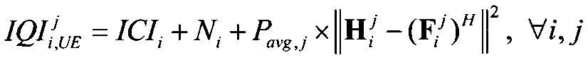 式(14)
式(14)
 In the latter feedback method, for example, in the first mode, the calculated values IQI i and UE j fed back by the mobile terminal apparatus are values shown in the following formula (13). The calculated values IQI i and UE j are transmitted to the radio base station apparatus. In the radio base station apparatus, the average total transmission power (P avg, j ) of the radio base station apparatus j is known (for example, by exchanging information between radio base stations in the cluster). i, eNB j = IQI i j is obtained (the following formula (14)).
Formula (13)
Formula (14)
式(13)
Formula (13)
同様に、第2態様では、移動端末装置がフィードバックする計算値IQIi,UE
jは上記式(9)の分母で計算される値である。この計算値IQIi,UE
j(接続セル及び協調セル)を無線基地局装置に送信する。無線基地局装置においては、無線基地局装置iの平均総送信電力(Pavg,j)とが既知であるので、このパラメータを用いてIQIi,eNB
j=IQIi
jを求める。また、同様に、第3態様では、移動端末装置がフィードバックする計算値IQIi,UE
jは上記式(8)の分母で計算される値である。この計算値IQIi,UE
j(接続セル及び協調セル)を無線基地局装置に送信する。無線基地局装置においては、無線基地局装置iの平均総送信電力(Pavg,j)とが既知であるので、このパラメータを用いてIQIi,eNB
j=IQIi
jを求める。
Similarly, in the second mode, the calculated values IQI i and UE j fed back by the mobile terminal apparatus are values calculated using the denominator of the above equation (9). This calculated value IQI i, UE j (connected cell and cooperative cell) is transmitted to the radio base station apparatus. In the radio base station apparatus, since the average total transmission power (P avg, j ) of the radio base station apparatus i is known, IQI i, eNB j = IQI i j is obtained using this parameter. Similarly, in the third mode, the calculated values IQI i and UE j fed back by the mobile terminal apparatus are values calculated by the denominator of the above equation (8). This calculated value IQI i, UE j (connected cell and cooperative cell) is transmitted to the radio base station apparatus. In the radio base station apparatus, since the average total transmission power (P avg, j ) of the radio base station apparatus i is known, IQI i, eNB j = IQI i j is obtained using this parameter.
上述した第1態様~第5態様において、量子化誤差を考慮したIQIの計算では、瞬時値を用いている。IQIを用いてプリコーディングウェイトを生成する場合に、さらに精度を高くするためには、IQI値を時間平均化することが望ましい。具体的には、下記式(15)に示すように、時刻TにおけるIQIの平均値及び時刻T+1におけるIQI瞬時値を用いて、時刻T+1におけるIQIの平均値(時間平均値)を求めて、この時間平均値を無線基地局装置にフィードバックする。
In the first to fifth aspects described above, instantaneous values are used in the IQI calculation considering the quantization error. When generating precoding weights using IQI, it is desirable to average the IQI values over time in order to further increase the accuracy. Specifically, as shown in the following formula (15), using the IQI average value at time T and the IQI instantaneous value at time T + 1, the average IQI value (time average value) at time T + 1 is obtained, and this The time average value is fed back to the radio base station apparatus.
式(15)
 (IQIi
j)T+1:サブフレーム(T+1)におけるIQIの瞬時値
(IQIi
j)T+1:サブフレーム(T+1)におけるIQIの瞬時値
(IQIi,avg j)T+1:IQIのサブフレーム(T+1)における平均値
T+1:平均化の時間窓の長さ Formula (15)
(IQI i j ) T + 1 : instantaneous IQI value in subframe (T + 1) (IQI i, avg j ) T + 1 : average value in IQI subframe (T + 1) T + 1: length of time window of averaging
(IQIi,avg j)T+1:IQIのサブフレーム(T+1)における平均値
T+1:平均化の時間窓の長さ Formula (15)
IQIの時間平均化については、移動端末装置側で行っても良く、無線基地局装置側で行っても良い。すなわち、移動端末装置において、IQI瞬時値を求めて、このIQI瞬時値を無線基地局装置にフィードバックし、無線基地局装置において、上記式(15)に示すように、IQIの時間平均化を行っても良い。なお、一般的には、IQIの時間平均区間の方がCQIの時間平均区間よりも長い。
The IQI time averaging may be performed on the mobile terminal device side or on the radio base station device side. That is, the mobile terminal apparatus obtains an IQI instantaneous value, feeds back this IQI instantaneous value to the radio base station apparatus, and the radio base station apparatus performs time averaging of IQI as shown in the above equation (15). May be. In general, the IQI time average interval is longer than the CQI time average interval.
また、下記式(16)に示すように、時刻T+1におけるIQI瞬時値と時刻TにおけるIQI平均値とについて重み付けをして平均化しても良い。この場合において、平均値に比較し瞬時値への重み付けを高くしたい場合には、時刻T+1におけるIQI瞬時値の重みを大きくし、瞬時値に比較し平均値への重み付けを高くしたい場合には、時刻TにおけるIQI平均値の重みを大きくする。これにより、αの値を変化させて、瞬時値及び平均値に対する重み付けを調整することができる。
式(16)
 Further, as shown in the following equation (16), the IQI instantaneous value at time T + 1 and the IQI average value at time T may be weighted and averaged. In this case, when it is desired to increase the weighting of the instantaneous value compared to the average value, the weighting of the IQI instantaneous value at time T + 1 is increased, and when the weighting of the average value is increased compared to the instantaneous value, The IQI average value weight at time T is increased. Thereby, the value of (alpha) can be changed and the weighting with respect to an instantaneous value and an average value can be adjusted.
Formula (16)
式(16)
Formula (16)
このように、IQIを時間平均化することにより、IQI算出精度を向上することができ、SLNRプリコーディングウェイトの精度を向上することができる。
Thus, IQI calculation accuracy can be improved by time averaging IQI, and the accuracy of the SLNR precoding weight can be improved.
以下、本発明の実施の形態について、添付図面を参照して詳細に説明する。ここでは、LTE-Aシステムに対応する無線基地局装置及び移動端末装置を用いる場合について説明する。
Hereinafter, embodiments of the present invention will be described in detail with reference to the accompanying drawings. Here, a case where a radio base station apparatus and a mobile terminal apparatus corresponding to the LTE-A system are used will be described.
図3を参照しながら、本発明の一実施の形態に係る移動端末装置(UE:User Equipment)10及び無線基地局装置(eNodeB)20を有する移動通信システム1について説明する。図3は、本発明の一実施の形態に係る移動端末装置10及び無線基地局装置20を有する移動通信システム1の構成を説明するための図である。なお、図3に示す移動通信システム1は、例えば、LTEシステム又はSUPER 3Gが包含されるシステムである。また、この移動通信システム1は、IMT-Advancedと呼ばれても良いし、4Gと呼ばれても良い。
A mobile communication system 1 having a mobile terminal apparatus (UE: User Equipment) 10 and a radio base station apparatus (eNodeB) 20 according to an embodiment of the present invention will be described with reference to FIG. FIG. 3 is a diagram for explaining a configuration of the mobile communication system 1 including the mobile terminal apparatus 10 and the radio base station apparatus 20 according to the embodiment of the present invention. Note that the mobile communication system 1 shown in FIG. 3 is a system including, for example, an LTE system or SUPER 3G. The mobile communication system 1 may be called IMT-Advanced or 4G.
図3に示すように、移動通信システム1は、無線基地局装置20と、この無線基地局装置20と通信する複数の移動端末装置10(101、102、103、・・・10n、nはn>0の整数)とを含んで構成されている。無線基地局装置20は、上位局装置30と接続され、この上位局装置30は、コアネットワーク40と接続される。移動端末装置10は、セル50において無線基地局装置20と通信を行っている。なお、上位局装置30には、例えば、アクセスゲートウェイ装置、無線ネットワークコントローラ(RNC)、モビリティマネジメントエンティティ(MME)等が含まれるが、これに限定されるものではない。
As shown in FIG. 3, the mobile communication system 1 includes a radio base station apparatus 20 and a plurality of mobile terminal apparatuses 10 (10 1 , 10 2 , 10 3 ,... 10 n that communicate with the radio base station apparatus 20. , N is an integer of n> 0). The radio base station apparatus 20 is connected to the higher station apparatus 30, and the higher station apparatus 30 is connected to the core network 40. The mobile terminal apparatus 10 communicates with the radio base station apparatus 20 in the cell 50. The upper station device 30 includes, for example, an access gateway device, a radio network controller (RNC), a mobility management entity (MME), and the like, but is not limited thereto.
各移動端末装置(101、102、103、・・・10n)は、同一の構成、機能、状態を有するので、以下においては、特段の断りがない限り移動端末装置10として説明を進める。また、説明の便宜上、無線基地局装置20と無線通信するのは移動端末装置10であるものとして説明するが、より一般的には移動端末装置も固定端末装置も含むユーザ装置(UE)でよい。
Since each mobile terminal apparatus (10 1 , 10 2 , 10 3 ,... 10 n ) has the same configuration, function, and state, the following description will be given as the mobile terminal apparatus 10 unless otherwise specified. Proceed. For convenience of explanation, it is assumed that the mobile terminal device 10 is in radio communication with the radio base station device 20, but more generally a user device (UE) including both the mobile terminal device and the fixed terminal device may be used. .
移動通信システム1においては、無線アクセス方式として、下りリンクについてはOFDMA(直交周波数分割多元接続)が、上りリンクについてはSC-FDMA(シングルキャリア-周波数分割多元接続)が適用される。OFDMAは、周波数帯域を複数の狭い周波数帯域(サブキャリア)に分割し、各サブキャリアにデータをマッピングして通信を行うマルチキャリア伝送方式である。SC-FDMAは、システム帯域を端末毎に1つ又は連続したリソースブロックからなる帯域に分割し、複数の端末が互いに異なる帯域を用いることで、端末間の干渉を低減するシングルキャリア伝送方式である。
In the mobile communication system 1, OFDMA (Orthogonal Frequency Division Multiple Access) is applied to the downlink and SC-FDMA (Single Carrier Frequency Division Multiple Access) is applied to the uplink as the radio access scheme. OFDMA is a multi-carrier transmission scheme that performs communication by dividing a frequency band into a plurality of narrow frequency bands (subcarriers) and mapping data to each subcarrier. SC-FDMA is a single carrier transmission method that reduces interference between terminals by dividing a system band into bands each consisting of one or continuous resource blocks for each terminal, and a plurality of terminals using different bands. .
ここで、LTEシステムにおける通信チャネルについて説明する。下りリンクについては、各移動端末装置10で共有されるPDSCHと、下りL1/L2制御チャネル(PDCCH、PCFICH、PHICH)とが用いられる。このPDSCHにより、ユーザデータ、すなわち、通常のデータ信号が伝送される。送信データは、このユーザデータに含まれる。なお、無線基地局装置20で移動端末装置10に割り当てたCCやスケジューリング情報は、L1/L2制御チャネルにより移動端末装置10に通知される。
Here, communication channels in the LTE system will be described. For the downlink, PDSCH shared by each mobile terminal apparatus 10 and downlink L1 / L2 control channels (PDCCH, PCFICH, PHICH) are used. User data, that is, a normal data signal is transmitted by this PDSCH. Transmission data is included in this user data. Note that the CC and scheduling information assigned to the mobile terminal apparatus 10 by the radio base station apparatus 20 are notified to the mobile terminal apparatus 10 through the L1 / L2 control channel.
上りリンクについては、各移動端末装置10で共有して使用されるPUSCH(Physical Uplink Shared Channel)と、上りリンクの制御チャネルであるPUCCH(Physical Uplink Control Channel)とが用いられる。このPUSCHにより、ユーザデータが伝送される。また、PUCCHにより、下りリンクの無線品質情報(CQI:Channel Quality Indicator)などが伝送される。
For uplink, PUSCH (Physical Uplink Shared Channel) shared and used by each mobile terminal device 10 and PUCCH (Physical Uplink Control Channel) which is an uplink control channel are used. User data is transmitted by this PUSCH. Also, downlink radio quality information (CQI: Channel Quality Indicator) and the like are transmitted by PUCCH.
図4は、本実施の形態に係る移動端末装置10の構成を示すブロック図である。図5は、本実施の形態に係る無線基地局装置20の構成を示すブロック図である。なお、図4及び図5に示す移動端末装置10及び無線基地局装置20の構成は、本発明を説明するために簡略化したものであり、それぞれ通常の無線基地局装置及び移動端末装置が有する構成は備えているものとする。
FIG. 4 is a block diagram showing a configuration of mobile terminal apparatus 10 according to the present embodiment. FIG. 5 is a block diagram showing a configuration of radio base station apparatus 20 according to the present embodiment. Note that the configurations of the mobile terminal apparatus 10 and the radio base station apparatus 20 shown in FIG. 4 and FIG. 5 are simplified to explain the present invention, and the normal radio base station apparatus and the mobile terminal apparatus respectively have The configuration shall be provided.
図4に示す移動端末装置10において、無線基地局装置20から送出された送信信号は、受信アンテナRX#1~RX#Nにより受信され、デュプレクサ(Duplexer)101#1~101#Nにて送信経路と受信経路とに電気的に分離された後、RF受信回路102#1~102#Nに出力される。そして、RF受信回路102#1~102#Nにて、無線周波数信号からベースバンド信号に変換する周波数変換処理が施される。周波数変換処理が施されたベースバンド信号は、サイクリックプレフィクス(CP)除去部103#1~103#NにてCPが除去された後、高速フーリエ変換部(FFT部)104#1~104#Nに出力される。受信タイミング推定部105は、受信信号に含まれるリファレンス信号から受信タイミングを推定し、その推定結果をCP除去部103#1~103#Nに通知する。FFT部104#1~104#Nは、入力された受信信号にフーリエ変換を施し、時系列の信号から周波数領域の信号に変換する。周波数領域の信号に変換された受信信号は、データチャネル信号復調部106に出力される。
In the mobile terminal apparatus 10 shown in FIG. 4, the transmission signal transmitted from the radio base station apparatus 20 is received by the reception antennas RX # 1 to RX # N and transmitted by the duplexers 101 # 1 to 101 # N. After being electrically separated into a path and a receiving path, the signals are output to the RF receiving circuits 102 # 1 to 102 # N. Then, the RF receiving circuits 102 # 1 to 102 # N perform frequency conversion processing for converting radio frequency signals into baseband signals. The baseband signal subjected to the frequency conversion processing is subjected to cyclic prefix (CP) removal units 103 # 1 to 103 # N after the CP is removed, and then to a fast Fourier transform unit (FFT unit) 104 # 1 to 104. Is output to #N. Reception timing estimation section 105 estimates the reception timing from the reference signal included in the reception signal and notifies the estimation results to CP removal sections 103 # 1 to 103 # N. The FFT units 104 # 1 to 104 # N perform a Fourier transform on the input received signals, and convert the time series signals into frequency domain signals. The received signal converted into the frequency domain signal is output to data channel signal demodulation section 106.
データチャネル信号復調部106は、FFT部104#1~104#Nから入力された受信信号を、例えば、平均2乗誤差最小(MMSE:Minimum Mean Squared Error)や最尤推定検出(MLD:Maximum Likelihood Detection)信号分離法により分離する。これにより、無線基地局装置20から到来した受信信号は、ユーザ#1~ユーザ#kに関する受信信号に分離され、移動端末装置10のユーザ(ここでは、ユーザkとする)に関する受信信号が抽出される。チャネル推定部107は、FFT部104#1~104#Nから出力された受信信号に含まれるリファレンス信号からチャネル状態を推定し、推定したチャネル状態をデータチャネル信号復調部106と、後述するチャネル品質測定部110及びPMI選択部111とに通知する。データチャネル信号復調部106においては、通知されたチャネル状態に基づいて、受信信号を上述したMLD信号分離法により分離する。これにより、ユーザkに関する受信信号が復調される。
The data channel signal demodulator 106 uses, for example, the minimum mean square error (MMSE) or maximum likelihood estimation detection (MLD: Maximum Likelihood) for the received signals input from the FFT units 104 # 1 to 104 # N. Detection) Separation by signal separation method. As a result, the received signal arriving from the radio base station apparatus 20 is separated into received signals related to the users # 1 to #k, and the received signals related to the user of the mobile terminal apparatus 10 (here, user k) are extracted. The The channel estimation unit 107 estimates the channel state from the reference signal included in the received signals output from the FFT units 104 # 1 to 104 # N, and the estimated channel state is compared with the data channel signal demodulation unit 106 and channel quality described later. The measurement unit 110 and the PMI selection unit 111 are notified. Data channel signal demodulating section 106 separates the received signal by the above-described MLD signal separation method based on the notified channel state. Thereby, the received signal regarding the user k is demodulated.
なお、データチャネル信号復調部106による復調処理に先だって、抽出されたユーザkに関する受信信号は、不図示のサブキャリアデマッピング部にてデマッピングされて時系列の信号に戻されているものとする。データチャネル信号復調部106で復調されたユーザkに関する受信信号は、チャネル復号部108に出力される。そして、チャネル復号部108にてチャネル復号処理が施されることで送信信号#kが再生される。
Note that prior to the demodulation processing by the data channel signal demodulating unit 106, it is assumed that the extracted received signal regarding the user k is demapped by a subcarrier demapping unit (not shown) and returned to a time-series signal. . The received signal related to user k demodulated by data channel signal demodulation section 106 is output to channel decoding section 108. Then, the channel decoding unit 108 performs channel decoding processing to reproduce the transmission signal #k.
IQI測定部109は、少なくともチャネル推定部107から通知されたチャネル状態(チャネル推定値)及び後述するPMI選択部111で選択されたPMIを用いてIQIを測定する。すなわち、IQI測定部109は、少なくとも各無線基地局装置の平均送信電力及び移動端末装置側の量子化誤差を用いて上記式によりIQIを求める。例えば、第1態様においては、接続セルのIQI及び協調セルのIQIを上記式(5)又は式(7)により算出する。また、第2態様においては、接続セルのIQI及び協調セルのIQIを上記式(9)により算出する。第3態様においては、接続セルのIQI及び協調セルのIQIを上記式(10)により算出する。第4態様においては、接続セルのIQI及び協調セルのIQIを上記式(11)により算出する。
The IQI measurement unit 109 measures the IQI using at least the channel state (channel estimation value) notified from the channel estimation unit 107 and the PMI selected by the PMI selection unit 111 described later. That is, IQI measurement section 109 obtains IQI by the above formula using at least the average transmission power of each radio base station apparatus and the quantization error on the mobile terminal apparatus side. For example, in the first mode, the IQI of the connected cell and the IQI of the cooperative cell are calculated by the above formula (5) or formula (7). In the second mode, the IQI of the connected cell and the IQI of the cooperative cell are calculated by the above equation (9). In the third mode, the IQI of the connected cell and the IQI of the cooperative cell are calculated by the above equation (10). In the fourth aspect, the IQI of the connected cell and the IQI of the cooperative cell are calculated by the above equation (11).
IQI測定部109は、上述した第1フィードバック方法においては、少なくともチャネル状態及びPMIを用いて上記式(5)、式(7)、式(9)、式(10)、式(11)によりIQIを算出し、上述した第2フィードバック方法においては、少なくともチャネル状態及びPMIを用いて上記式(5)、式(7)、式(9)、式(10)、式(11)の分母の計算値(IQIi,UE
j)を算出する。IQI測定部109は、算出されたIQIあるいはIQIi,UE
jをフィードバック制御信号生成部112に出力する。また、IQI測定部109は、必要に応じて、上記式(15)、式(16)によりIQIを時間平均化する。
In the first feedback method described above, the IQI measurement unit 109 uses at least the channel state and the PMI to perform IQI according to the above equations (5), (7), (9), (10), and (11). In the second feedback method described above, at least the channel state and the PMI are used to calculate the denominators of the above equations (5), (7), (9), (10), and (11). The value (IQI i, UE j ) is calculated. The IQI measurement unit 109 outputs the calculated IQI or IQI i, UE j to the feedback control signal generation unit 112. Moreover, the IQI measurement part 109 carries out time average of IQI by said Formula (15) and Formula (16) as needed.
チャネル品質測定部110は、チャネル推定部107から通知されたチャネル状態に基づいてチャネル品質(CQI)を測定する。そして、測定結果であるCQIをフィードバック制御信号生成部110に出力する。PMI選択部111は、チャネル推定部107から通知されたチャネル状態に基づいて、PMIを選択する。そして、選択したPMIをフィードバック制御信号生成部112に出力する。
The channel quality measurement unit 110 measures the channel quality (CQI) based on the channel state notified from the channel estimation unit 107. Then, the CQI that is the measurement result is output to the feedback control signal generation unit 110. The PMI selection unit 111 selects a PMI based on the channel state notified from the channel estimation unit 107. Then, the selected PMI is output to the feedback control signal generation unit 112.
フィードバック制御信号生成部112においては、IQI測定部109からのIQIあるいはIQIi,UE
j、チャネル品質測定部110からのCQI、及びPMI選択部111からのPMIを用いて、これらを無線基地局装置20にフィードバックする制御信号(例えば、PUCCH)が生成される。フィードバック制御信号生成部112で生成された制御信号は、マルチプレクサ(MUX)117に出力される。
The feedback control signal generation unit 112 uses the IQI or IQI i, UE j from the IQI measurement unit 109, the CQI from the channel quality measurement unit 110, and the PMI from the PMI selection unit 111, and these are used as a radio base station apparatus. A control signal (eg, PUCCH) that feeds back to 20 is generated. The control signal generated by the feedback control signal generation unit 112 is output to the multiplexer (MUX) 117.
上位レイヤから送出されたユーザ#kに関する送信データ#kは、チャネル符号化部113によりチャネル符号化された後、データ変調部114にてデータ変調される。データ変調部114にてデータ変調された送信データ#kは、不図示の直並列変換部で、時系列の信号から周波数領域の信号に変換されてサブキャリアマッピング部115に出力される。
Transmission data #k related to user #k sent from the higher layer is channel-encoded by channel encoder 113 and then data-modulated by data modulator 114. Transmission data #k data-modulated by data modulation section 114 is converted from a time-series signal to a frequency domain signal by a serial / parallel conversion section (not shown) and output to subcarrier mapping section 115.
サブキャリアマッピング部115においては、送信データ#kを、無線基地局装置20から指示されたスケジュール情報に応じてサブキャリアにマッピングする。このとき、サブキャリアマッピング部115は、不図示の参照信号生成部により生成された参照信号#kを、送信データ#kと共にサブキャリアにマッピング(多重)する。このようにしてサブキャリアにマッピングされた送信データ#kがプリコーディング乗算部116に出力される。
The subcarrier mapping unit 115 maps the transmission data #k to subcarriers according to the schedule information instructed from the radio base station apparatus 20. At this time, subcarrier mapping section 115 maps (multiplexes) reference signal #k generated by a reference signal generation section (not shown) to subcarriers together with transmission data #k. Transmission data #k mapped to subcarriers in this way is output to precoding multiplication section 116.
プリコーディング乗算部116は、PMI選択部111で選択されたPMIから得られるプリコーディングウェイトに基づいて、受信アンテナRX#1~RX#N毎に送信データ#kを位相及び/又は振幅シフトする。プリコーディング乗算部116により位相及び/又は振幅シフトされた送信データ#kは、マルチプレクサ(MUX)117に出力される。
The precoding multiplication unit 116 shifts the phase and / or amplitude of the transmission data #k for each of the reception antennas RX # 1 to RX # N based on the precoding weight obtained from the PMI selected by the PMI selection unit 111. The transmission data #k phase-shifted and / or amplitude-shifted by the precoding multiplier 116 is output to the multiplexer (MUX) 117.
マルチプレクサ(MUX)117においては、位相及び/又は振幅シフトされた送信データ#kと、フィードバック制御信号生成部112により生成された制御信号とを合成し、受信アンテナRX#1~RX#N毎の送信信号を生成する。マルチプレクサ(MUX)117により生成された送信信号は、逆高速フーリエ変換部118#1~118#Nにて逆高速フーリエ変換して周波数領域の信号から時間領域の信号に変換された後、CP付加部119#1~119#NでCPが付加されてRF送信回路119#1~119#Nへ出力される。そして、RF送信回路120#1~120#Nで無線周波数帯に変換する周波数変換処理が施された後、デュプレクサ(Duplexer)101#1~101#Nを介して受信アンテナRX#1~RX#Nに出力され、受信アンテナRX#1~RX#Nから上りリンクで無線基地局装置20に送出される。
The multiplexer (MUX) 117 synthesizes the transmission data #k shifted in phase and / or amplitude and the control signal generated by the feedback control signal generation unit 112, and receives each of the reception antennas RX # 1 to RX # N. A transmission signal is generated. The transmission signal generated by the multiplexer (MUX) 117 is subjected to inverse fast Fourier transform by an inverse fast Fourier transform unit 118 # 1 to 118 # N, converted from a frequency domain signal to a time domain signal, and then subjected to CP addition. CPs are added by the units 119 # 1 to 119 # N and output to the RF transmission circuits 119 # 1 to 119 # N. Then, after frequency conversion processing for conversion to a radio frequency band is performed by the RF transmission circuits 120 # 1 to 120 # N, the reception antennas RX # 1 to RX # are passed through the duplexers 101 # 1 to 101 # N. N is transmitted to the radio base station apparatus 20 via the uplink from the reception antennas RX # 1 to RX # N.
図5に示す無線基地局装置20において、不図示のスケジューラは、後述するチャネル推定部215#1~215#kから与えられるチャネル推定値に基づいて多重するユーザ数(多重ユーザ数)を決定する。そして、各ユーザに対する上下リンクのリソース割り当て内容(スケジューリング情報)を決定し、ユーザ#1~#kに対する送信データ#1~#kを対応するチャネル符号化部201#1~201#kに送出する。
In radio base station apparatus 20 shown in FIG. 5, a scheduler (not shown) determines the number of users to be multiplexed (the number of multiplexed users) based on channel estimation values given from channel estimation sections 215 # 1 to 215 # k described later. . Then, uplink / downlink resource allocation contents (scheduling information) for each user are determined, and transmission data # 1 to #k for users # 1 to #k are transmitted to corresponding channel coding sections 201 # 1 to 201 # k. .
送信データ#1~#kは、チャネル符号化部201#1~201#kでチャネル符号化された後、データ変調部202#1~202#kに出力され、データ変調される。この際、チャネル符号化及びデータ変調は、後述するCQI処理部220#1~220#kから与えられるチャネル符号化率及び変調方式に基づいて行われる。データ変調部202#1~202#kでデータ変調された送信データ#1~#kは、不図示の離散フーリエ変換部で逆フーリエ変換され、時系列の信号から周波数領域の信号に変換されてサブキャリアマッピング部203に出力される。
Transmission data # 1 to #k are channel-encoded by channel encoders 201 # 1 to 201 # k, and then output to data modulators 202 # 1 to 202 # k for data modulation. At this time, channel coding and data modulation are performed based on channel coding rates and modulation schemes provided from CQI processing sections 220 # 1 to 220 # k described later. Transmission data # 1 to #k data-modulated by data modulators 202 # 1 to 202 # k are subjected to inverse Fourier transform by a discrete Fourier transform unit (not shown), and converted from a time-series signal to a frequency domain signal. It is output to the subcarrier mapping unit 203.
サブキャリアマッピング部203においては、送信データ#1~#kを、スケジューラから与えられるスケジュール情報に応じてサブキャリアにマッピングする。このとき、サブキャリアマッピング部203は、不図示の参照信号生成部から入力される参照信号#1~#kを、送信データ#1~#kと共にサブキャリアにマッピング(多重)する。このようにしてサブキャリアにマッピングされた送信データ#1~#kがプリコーディング乗算部204#1~204#kに出力される。
The subcarrier mapping unit 203 maps the transmission data # 1 to #k to subcarriers according to the schedule information given from the scheduler. At this time, subcarrier mapping section 203 maps (multiplexes) reference signals # 1 to #k input from a reference signal generation section (not shown) to subcarriers together with transmission data # 1 to #k. Transmission data # 1 to #k mapped to subcarriers in this way are output to precoding multiplication sections 204 # 1 to 204 #k.
プリコーディング乗算部204#1~204#kは、後述するプリコーディングウェイト生成部221から与えられるプリコーディングウェイトに基づいて、送信アンテナTX#1~TX#N毎に送信データ#1~#kを位相及び/又は振幅シフトする(プリコーディングによる送信アンテナTX#1~送信アンテナTX#Nの重み付け)。プリコーディング乗算部204#1~204#kにより位相及び/又は振幅シフトされた送信データ#1~#kは、マルチプレクサ(MUX)205に出力される。
Precoding multiplication sections 204 # 1 to 204 # k transmit transmission data # 1 to #k for each of transmission antennas TX # 1 to TX # N based on a precoding weight given from precoding weight generation section 221 to be described later. Phase and / or amplitude shift (weighting of transmit antenna TX # 1 to transmit antenna TX # N by precoding). Transmission data # 1 to #k whose phases and / or amplitudes are shifted by precoding multiplication sections 204 # 1 to 204 #k are output to multiplexer (MUX) 205.
マルチプレクサ(MUX)205においては、位相及び/又は振幅シフトされた送信データ#1~#kを合成し、送信アンテナTX#1~TX#N毎の送信信号を生成する。マルチプレクサ(MUX)205により生成された送信信号は、逆高速フーリエ変換部206#1~206#Nにて逆高速フーリエ変換して周波数領域の信号から時間領域の信号に変換される。そして、サイクリックプレフィクス(CP)付加部207#1~207#NにてCPが付加された後、RF送信回路208#1~208#Nへ出力される。そして、RF送信回路208#1~208#Nで無線周波数帯に変換する周波数変換処理が施された後、デュプレクサ(Duplexer)209#1~209#Nを介して送信アンテナTX#1~TX#Nに出力され、送信アンテナTX#1~TX#Nから下りリンクで移動端末装置10に送出される。
In the multiplexer (MUX) 205, the transmission data # 1 to #k shifted in phase and / or amplitude are combined to generate transmission signals for the transmission antennas TX # 1 to TX # N. The transmission signal generated by the multiplexer (MUX) 205 is subjected to inverse fast Fourier transform by the inverse fast Fourier transform units 206 # 1 to 206 # N to be converted from a frequency domain signal to a time domain signal. Then, after the CP is added by the cyclic prefix (CP) adding units 207 # 1 to 207 # N, they are output to the RF transmission circuits 208 # 1 to 208 # N. Then, after frequency conversion processing for conversion to a radio frequency band is performed by the RF transmission circuits 208 # 1 to 208 # N, the transmission antennas TX # 1 to TX # are transmitted via the duplexers 209 # 1 to 209 # N. N is transmitted from the transmission antennas TX # 1 to TX # N to the mobile terminal apparatus 10 on the downlink.
一方、移動端末装置10から上りリンクで送出された送信信号は、送信アンテナTX#1~TX#Nにより受信され、デュプレクサ(Duplexer)209#1~209#Nにて送信経路と受信経路とに電気的に分離された後、RF受信回路210#1~210#Nに出力される。そして、RF受信回路210#1~210#Nにて、無線周波数信号からベースバンド信号に変換する周波数変換処理が施される。周波数変換処理が施されたベースバンド信号は、CP除去部211#1~211#NにてCPが除去された後、高速フーリエ変換部(FFT部)212#1~212#Nに出力される。受信タイミング推定部213は、受信信号に含まれるリファレンス信号から受信タイミングを推定し、その推定結果をCP除去部211#1~211#Nに通知する。FFT部212#1~212#Nは、入力された受信信号にフーリエ変換を施し、時系列の信号から周波数領域の信号に変換する。これらの周波数領域の信号に変換された受信信号は、データチャネル信号分離部214#1~214#kに出力される。
On the other hand, the transmission signal transmitted from the mobile terminal apparatus 10 in the uplink is received by the transmission antennas TX # 1 to TX # N, and is transmitted to the transmission path and the reception path by the duplexers 209 # 1 to 209 # N. After being electrically separated, the signals are output to the RF receiving circuits 210 # 1 to 210 # N. Then, frequency conversion processing for converting the radio frequency signal into the baseband signal is performed in the RF receiving circuits 210 # 1 to 210 # N. The baseband signal subjected to the frequency conversion process is output to the fast Fourier transform units (FFT units) 212 # 1 to 212 # N after the CPs are removed by the CP removal units 211 # 1 to 211 # N. . Reception timing estimation section 213 estimates the reception timing from the reference signal included in the reception signal, and notifies the CP removal sections 211 # 1 to 211 # N of the estimation result. The FFT units 212 # 1 to 212 # N perform Fourier transform on the input received signals, and convert the time series signals into frequency domain signals. The received signals converted into these frequency domain signals are output to data channel signal demultiplexing sections 214 # 1 to 214 # k.
データチャネル信号分離部214#1~214#kは、FFT部212#1~212#kから入力された受信信号を、例えば、平均2乗誤差最小(MMSE:Minimum Mean Squared Error)や最尤推定検出(MLD:Maximum Likelihood Detection)信号分離法により分離する。これにより、移動端末装置10から到来した受信信号は、ユーザ#1~ユーザ#kに関する受信信号に分離される。チャネル推定部215#1~215#kは、FFT部212#1~212#kから出力された受信信号に含まれるリファレンス信号からチャネル状態を推定し、推定したチャネル状態をデータチャネル信号分離部214#1~214#k及び制御チャネル信号復調部216#1~216#kに通知する。データチャネル信号分離部214#1~214#kにおいては、通知されたチャネル状態に基づいて、受信信号を上述したMLD信号分離法により分離する。
The data channel signal demultiplexing sections 214 # 1 to 214 # k use, for example, the minimum mean square error (MMSE) or maximum likelihood estimation of the received signals input from the FFT sections 212 # 1 to 212 # k. It separates by the detection (MLD: Maximum Likelihood Detection) signal separation method. As a result, the received signal that has arrived from the mobile terminal apparatus 10 is separated into received signals related to the users # 1 to #k. Channel estimation sections 215 # 1 to 215 # k estimate the channel state from the reference signal included in the received signals output from FFT sections 212 # 1 to 212 # k, and the estimated channel state is data channel signal separation section 214. # 1 to 214 # k and control channel signal demodulation sections 216 # 1 to 216 # k are notified. Data channel signal separation sections 214 # 1 to 214 # k separate received signals by the MLD signal separation method described above based on the notified channel state.
データチャネル信号分離部214#1~214#kにより分離されたユーザ#1~ユーザ#kに関する受信信号は、不図示のサブキャリアデマッピング部にてデマッピングされて時系列の信号に戻された後、不図示のデータ復調部でデータ復調される。そして、チャネル復号部217#1~217#kにてチャネル復号処理が施されることで送信信号#1~送信信号#kが再生される。
The received signals related to user # 1 to user #k separated by data channel signal separation sections 214 # 1 to 214 # k are demapped by a subcarrier demapping section (not shown) and returned to a time-series signal. Thereafter, the data is demodulated by a data demodulator (not shown). Channel decoding sections 217 # 1 to 217 # k perform channel decoding processing to reproduce transmission signals # 1 to #k.
制御チャネル信号復調部216#1~216#kは、FFT部212#1~212#kから入力された受信信号に含まれる制御チャネル信号(例えば、PDCCH)を復調する。この際、制御チャネル信号復調部216#1~216#kは、それぞれユーザ#1~ユーザ#kに対応する制御チャネル信号を復調する。この際、制御チャネル信号復調部216#1~216#kにおいては、チャネル推定部215#1~215#kから通知されたチャネル状態に基づいて制御チャネル信号を復調する。制御チャネル信号復調部216#1~216#kにより復調された各制御チャネル信号は、PMI処理部218#1~218#k、IQI処理部219#1~219#k、及びCQI処理部220#1~220#kとに出力される。
Control channel signal demodulation sections 216 # 1 to 216 # k demodulate control channel signals (for example, PDCCH) included in the reception signals input from FFT sections 212 # 1 to 212 # k. At this time, control channel signal demodulation sections 216 # 1 to 216 # k demodulate control channel signals corresponding to users # 1 to #k, respectively. At this time, control channel signal demodulation sections 216 # 1 to 216 # k demodulate the control channel signal based on the channel state notified from channel estimation sections 215 # 1 to 215 # k. The control channel signals demodulated by the control channel signal demodulating units 216 # 1 to 216 # k are transmitted to the PMI processing units 218 # 1 to 218 # k, the IQI processing units 219 # 1 to 219 # k, and the CQI processing unit 220 #. 1 to 220 # k.
PMI処理部218#1~218#kは、制御チャネル信号復調部216#1~216#kから入力された各制御チャネル信号(例えば、PUCCH)に含まれる情報からPMIを抽出する。PMI処理部218#1~218#kにより再生されたPMIは、プリコーディングウェイト生成部221に出力される。
The PMI processing units 218 # 1 to 218 # k extract PMI from information included in each control channel signal (for example, PUCCH) input from the control channel signal demodulation units 216 # 1 to 216 # k. The PMI reproduced by the PMI processing units 218 # 1 to 218 # k is output to the precoding weight generation unit 221.
IQI処理部219#1~219#kは、制御チャネル信号復調部216#1~216#kから入力された各制御チャネル信号(例えば、PUCCH)に含まれる情報からIQIあるいはIQIi,UE
jを抽出する。また、IQI処理部219#1~219#kは、上述した第1フィードバック方法においては、抽出したIQIをプリコーディングウェイト生成部221に出力する。IQI処理部219#1~219#kは、上述した第2フィードバック方法においては、移動端末装置(UE)からの少なくともチャネル推定値及びPMIを含むIQI測定に必要な情報(上記式(5)、式(7)、式(9)、式(10)、式(11)に含まれるパラメータ)を用いてIQIを求める。すなわち、IQI処理部219#1~219#kは、抽出したIQIi,UE
jを用いて上記式(5)、式(7)、式(9)、式(10)、式(11)によりIQIを算出し、IQIをプリコーディングウェイト生成部221に出力する。
IQI processing sections 219 # 1 to 219 # k obtain IQI or IQI i, UE j from information included in each control channel signal (for example, PUCCH) input from control channel signal demodulation sections 216 # 1 to 216 # k. Extract. Also, IQI processing sections 219 # 1 to 219 # k output the extracted IQI to precoding weight generation section 221 in the first feedback method described above. In the second feedback method described above, the IQI processing units 219 # 1 to 219 # k receive information necessary for IQI measurement including at least a channel estimation value and PMI from the mobile terminal apparatus (UE) (the above equation (5), IQI is calculated | required using Formula (7), Formula (9), Formula (10), and the parameter contained in Formula (11). That is, the IQI processing units 219 # 1 to 219 # k use the extracted IQI i and UE j to perform the above equations (5), (7), (9), (10), and (11). IQI is calculated, and IQI is output to precoding weight generation section 221.
後者の場合、IQI処理部219#1~219#kは、例えば、第1態様においては、接続セルのIQI及び協調セルのIQIを上記式(5)又は式(7)により算出する。また、第2態様においては、接続セルのIQI及び協調セルのIQIを上記式(9)により算出する。第3態様においては、接続セルのIQI及び協調セルのIQIを上記式(10)により算出する。また、IQI処理部219#1~219#kは、必要に応じて、上記式(15)、式(16)によりIQIを時間平均化する。
In the latter case, for example, in the first mode, the IQI processing units 219 # 1 to 219 # k calculate the IQI of the connected cell and the IQI of the cooperative cell by the above formula (5) or formula (7). In the second mode, the IQI of the connected cell and the IQI of the cooperative cell are calculated by the above equation (9). In the third mode, the IQI of the connected cell and the IQI of the cooperative cell are calculated by the above equation (10). Further, the IQI processing units 219 # 1 to 219 # k average the IQI according to the above equations (15) and (16) as necessary.
CQI処理部220#1~220#kは、制御チャネル信号復調部216#1~216#kから入力された各制御チャネル信号(例えば、PUCCH)に含まれる参照信号からCQIを測定すると共に、常にCQI情報を最新の状態に更新する。CQI処理部220#1~220#kに更新されるCQI情報は、それぞれチャネル符号化部201#1~201#k、データ変調部202#1~202#kに出力される。
The CQI processing units 220 # 1 to 220 # k measure CQI from reference signals included in the control channel signals (for example, PUCCH) input from the control channel signal demodulation units 216 # 1 to 216 # k, and always Update the CQI information to the latest state. The CQI information updated to the CQI processing units 220 # 1 to 220 # k is output to the channel coding units 201 # 1 to 201 # k and the data modulation units 202 # 1 to 202 # k, respectively.
プリコーディングウェイト生成部221は、PMI処理部218#1~218#kから出力されたPMI及びIQI処理部219#1~219#kから出力されたIQIを用いて、送信データ#1~#kに対する位相及び/又は振幅シフト量を示すプリコーディングウェイトを生成する。生成された各プリコーディングウェイトは、プリコーディング乗算部204#1~204#kに出力され、送信データ#1~送信データ#kのプリコーディングに利用される。
Precoding weight generation section 221 uses transmission data # 1 to #k using PMI output from PMI processing sections 218 # 1 to 218 # k and IQI output from IQI processing sections 219 # 1 to 219 # k. A precoding weight indicating a phase shift amount and / or an amplitude shift amount is generated. Each generated precoding weight is output to precoding multiplication sections 204 # 1 to 204 # k, and is used for precoding transmission data # 1 to transmission data #k.
プリコーディングウェイト生成部220においては、以下のようにしてプリコーディングウェイトを生成する。まず、下記式(17)に示すようにPMIをチャネル係数とする(協調クラスタ内の無線基地局装置が3つ移動端末側の受信アンテナ数を2つと前提した場合)。
式(17)
 The precoding
 weight generation unit 220 generates precoding weights as follows. First, as shown in the following equation (17), PMI is used as a channel coefficient (when it is assumed that there are three radio base station apparatuses in the cooperative cluster and two reception antennas on the mobile terminal side).
Formula (17)
式(17)
Formula (17)
次いで、式(17)で得られたチャネル係数とIQIとから、下記式(18)により、接続セル(図1のeNB1)及び協調セル(図1のeNB2)のチャネル共分散行列を求める。
式(18)
(接続セル)
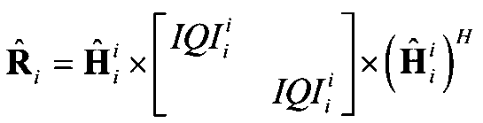 (協調セル)
 Next, the channel covariance matrix of the connected cell (eNB 1 in FIG. 1 ) and the cooperative cell (eNB 2 in FIG. 1) is obtained from the channel coefficient and IQI obtained in Equation (17) by the following equation (18). .
Formula (18)
(Connection cell)
(Cooperative cell)
式(18)
(接続セル)
Formula (18)
(Connection cell)
その後、接続セル及び協調セルのチャネル共分散行列から、下記式(19)によりSLNRプリコーディングにおけるプリコーディングウェイトを求める。
式(19)
 Thereafter, a precoding weight in SLNR precoding is obtained from the channel covariance matrix of the connected cell and the cooperative cell by the following equation (19).
Formula (19)
式(19)
Formula (19)
(第1フィードバック方法)
上記構成を有する移動通信システムにおいては、移動端末装置(UE)において、チャネル推定部107で下りリンク参照信号を用いてチャネル推定する。そして、PMI選択部111において、チャネル推定部107で得られたチャネル推定値を用いてPMIを選択する。次いで、IQI測定部109において、少なくともチャネル推定値及びPMIを用いてIQIを測定する。このとき、IQI測定部109は、上記第1態様~第3態様にしたがって式(5)、式(7)、式(9)、式(10)、式(11)によりIQIを算出する。このIQIは無線基地局装置eNBにフィードバックされる。 (First feedback method)
In the mobile communication system having the above-described configuration, thechannel estimation unit 107 performs channel estimation using the downlink reference signal in the mobile terminal apparatus (UE). Then, PMI selection section 111 selects a PMI using the channel estimation value obtained by channel estimation section 107. Next, IQI measurement section 109 measures IQI using at least the channel estimation value and PMI. At this time, IQI measuring section 109 calculates IQI according to equations (5), (7), (9), (10), and (11) according to the first to third aspects. This IQI is fed back to the radio base station apparatus eNB.
上記構成を有する移動通信システムにおいては、移動端末装置(UE)において、チャネル推定部107で下りリンク参照信号を用いてチャネル推定する。そして、PMI選択部111において、チャネル推定部107で得られたチャネル推定値を用いてPMIを選択する。次いで、IQI測定部109において、少なくともチャネル推定値及びPMIを用いてIQIを測定する。このとき、IQI測定部109は、上記第1態様~第3態様にしたがって式(5)、式(7)、式(9)、式(10)、式(11)によりIQIを算出する。このIQIは無線基地局装置eNBにフィードバックされる。 (First feedback method)
In the mobile communication system having the above-described configuration, the
無線基地局装置eNBにおいては、プリコーディングウェイト生成部221で、フィードバックされたPMI及びIQIを用いてプリコーディングウェイトを生成する。このとき、プリコーディングウェイト生成部221は、上記式(17)~式(19)によりプリコーディングウェイトを生成する。次いで、無線基地局装置eNBは、得られたプリコーディングウェイトを用い、MIMO伝送を利用して協調マルチポイント送信する。
In the radio base station apparatus eNB, the precoding weight generation unit 221 generates a precoding weight using the fed back PMI and IQI. At this time, the precoding weight generation unit 221 generates precoding weights according to the above equations (17) to (19). Next, the radio base station apparatus eNB performs cooperative multipoint transmission using MIMO transmission using the obtained precoding weight.
(第2フィードバック方法)
上記構成を有する移動通信システムにおいては、移動端末装置(UE)において、チャネル推定部107で下りリンク参照信号を用いてチャネル推定する。そして、PMI選択部111において、チャネル推定部107で得られたチャネル推定値を用いてPMIを選択する。次いで、IQI測定部109において、少なくともチャネル推定値及びPMIを用いてIQIi,UE jを算出する。このとき、IQI測定部109は、上記第1態様~第3態様にしたがって式(5)、式(7)、式(9)、式(10)、式(11)によりIQIi,UE jを算出する。このIQIi,UE jは無線基地局装置eNBにフィードバックされる。 (Second feedback method)
In the mobile communication system having the above-described configuration, thechannel estimation unit 107 performs channel estimation using the downlink reference signal in the mobile terminal apparatus (UE). Then, PMI selection section 111 selects a PMI using the channel estimation value obtained by channel estimation section 107. Next, IQI measurement section 109 calculates IQI i, UE j using at least the channel estimation value and PMI. At this time, the IQI measurement unit 109 calculates IQI i, UE j according to Equation (5), Equation (7), Equation (9), Equation (10), and Equation (11) according to the first to third aspects. calculate. The IQI i and UE j are fed back to the radio base station apparatus eNB.
上記構成を有する移動通信システムにおいては、移動端末装置(UE)において、チャネル推定部107で下りリンク参照信号を用いてチャネル推定する。そして、PMI選択部111において、チャネル推定部107で得られたチャネル推定値を用いてPMIを選択する。次いで、IQI測定部109において、少なくともチャネル推定値及びPMIを用いてIQIi,UE jを算出する。このとき、IQI測定部109は、上記第1態様~第3態様にしたがって式(5)、式(7)、式(9)、式(10)、式(11)によりIQIi,UE jを算出する。このIQIi,UE jは無線基地局装置eNBにフィードバックされる。 (Second feedback method)
In the mobile communication system having the above-described configuration, the
無線基地局装置eNBにおいては、IQI処理部219でIQIi,UE
jを用いてIQIを測定する。このとき、IQI処理部219は、上記第1態様~第3態様にしたがって式(5)、式(7)、式(9)、式(10)、式(11)によりIQIを算出する。次いで、プリコーディングウェイト生成部221で、フィードバックされたPMI及び算出されたIQIを用いてプリコーディングウェイトを生成する。このとき、プリコーディングウェイト生成部221は、上記式(17)~式(19)によりプリコーディングウェイトを生成する。次いで、無線基地局装置eNBは、得られたプリコーディングウェイトを用い、MIMO伝送を利用して協調マルチポイント送信する。
In the radio base station apparatus eNB, the IQI processing unit 219 measures IQI using IQI i and UE j . At this time, the IQI processing unit 219 calculates the IQI according to the expressions (5), (7), (9), (10), and (11) according to the first to third aspects. Next, the precoding weight generation unit 221 generates a precoding weight using the fed back PMI and the calculated IQI. At this time, the precoding weight generation unit 221 generates precoding weights according to the above equations (17) to (19). Next, the radio base station apparatus eNB performs cooperative multipoint transmission using MIMO transmission using the obtained precoding weight.
以上、上述の実施形態を用いて本発明について詳細に説明したが、当業者にとっては、本発明が本明細書中に説明した実施形態に限定されるものではないということは明らかである。本発明は、特許請求の範囲の記載により定まる本発明の趣旨及び範囲を逸脱することなく修正及び変更態様として実施することができる。従って、本明細書の記載は、例示説明を目的とするものであり、本発明に対して何ら制限的な意味を有するものではない。
As described above, the present invention has been described in detail using the above-described embodiments. However, it is obvious for those skilled in the art that the present invention is not limited to the embodiments described in the present specification. The present invention can be implemented as modified and changed modes without departing from the spirit and scope of the present invention defined by the description of the scope of claims. Therefore, the description of the present specification is for illustrative purposes and does not have any limiting meaning to the present invention.
本出願は、2011年3月4日出願の特願2011-047972に基づく。この内容は、全てここに含めておく。
This application is based on Japanese Patent Application No. 2011-047972 filed on March 4, 2011. All this content is included here.
Claims (17)
- 下りリンク参照信号を用いてチャネル推定するチャネル推定部と、前記チャネル推定部で得られたチャネル推定値を用いてPMI(Precoding Matrix Indicator)を選択するPMI選択部と、少なくとも前記チャネル推定値及び前記PMIを用いてIQI(Interference Quality Indicator)を測定するIQI測定部と、少なくとも前記PMI及び前記IQIを無線基地局装置に送信する送信部と、を具備することを特徴とする移動端末装置。 A channel estimation unit that performs channel estimation using a downlink reference signal, a PMI selection unit that selects a PMI (Precoding Matrix Indicator) using a channel estimation value obtained by the channel estimation unit, and at least the channel estimation value and the A mobile terminal apparatus comprising: an IQI measurement unit that measures an IQI (Interference Quality Indicator) using PMI; and a transmission unit that transmits at least the PMI and the IQI to a radio base station apparatus.
- 前記IQI測定部は、少なくとも各無線基地局装置の平均送信電力及び移動端末装置側の量子化誤差を用いてIQIを求めることを特徴とする請求項1記載の移動端末装置。 The mobile terminal apparatus according to claim 1, wherein the IQI measurement unit obtains an IQI using at least an average transmission power of each radio base station apparatus and a quantization error on the mobile terminal apparatus side.
- 前記IQI測定部は、下記式(5)を用いてIQIを求めることを特徴とする請求項1記載の移動端末装置。
式(5)
Hi j:下りリンクのチャネル状態
Fi j:移動端末装置iからのPMIフィードバック
Pavg,i:無線基地局装置iの平均総送信電力
ICIi:移動端末装置iでのCoMPセットに属するセルからの干渉を除く干渉
N:平均ノイズ The mobile terminal apparatus according to claim 1, wherein the IQI measurement unit obtains an IQI using the following equation (5).
Formula (5)
H i j : Channel state of downlink F i j : PMI feedback from mobile terminal apparatus i P avg, i : Average total transmission power of radio base station apparatus i ICI i : Cell belonging to CoMP set in mobile terminal apparatus i Interference excluding interference from N: Average noise - 前記IQI測定部は、下記式(9)を用いてIQIを求めることを特徴とする請求項1記載の移動端末装置。
式(9)
Hi j:下りリンクのチャネル状態
Fi j:移動端末装置iからのPMIフィードバック
Pavg,j:無線基地局装置jの平均総送信電力
ICIi:移動端末装置iでのCoMPセットに属するセルからの干渉を除く干渉
N:平均ノイズ The mobile terminal apparatus according to claim 1, wherein the IQI measurement unit obtains an IQI using the following equation (9).
Formula (9)
H i j : Channel state of downlink F i j : PMI feedback from mobile terminal apparatus i Pavg , j : Average total transmission power of radio base station apparatus j ICI i : Cell belonging to CoMP set in mobile terminal apparatus i Interference excluding interference from N: Average noise - 前記IQI測定部は、下記式(10)を用いてIQIを求めることを特徴とする請求項1記載の移動端末装置。
式(10)
Hi j:下りリンクのチャネル状態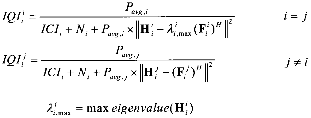
Fi j:移動端末装置iからのPMIフィードバック
Pavg,i:無線基地局装置iの平均総送信電力
ICIi:移動端末装置iでのCoMPセットに属するセルからの干渉を除く干渉
Ni:移動端末装置iの受信機における平均ノイズ The mobile terminal apparatus according to claim 1, wherein the IQI measurement unit obtains an IQI using the following equation (10).
Formula (10)
H i j : Channel state of downlink F i j : PMI feedback from mobile terminal apparatus i P avg, i : Average total transmission power of radio base station apparatus i ICI i : Cell belonging to CoMP set in mobile terminal apparatus i Interference excluding interference from N i : Average noise at receiver of mobile terminal device i - 前記IQI測定部は、下記式(15)を用いて時間平均化されたIQIを求めることを特徴とする請求項1記載の移動端末装置。
式(15)
(IQIi j)T+1:サブフレーム(T+1)におけるIQIの瞬時値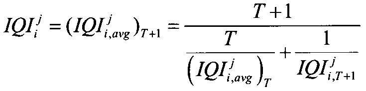
(IQIi,avg j)T+1:IQIのサブフレーム(T+1)における平均値
T+1:平均化の時間窓の長さ The mobile terminal apparatus according to claim 1, wherein the IQI measurement unit obtains a time-averaged IQI using the following equation (15).
Formula (15)
(IQI i j ) T + 1 : instantaneous IQI value in subframe (T + 1) (IQI i, avg j ) T + 1 : average value in IQI subframe (T + 1) T + 1: length of time window of averaging - 前記IQI測定部は、下記式(16)を用いて重み付けをして時間平均化されたIQIを求めることを特徴とする請求項1記載の移動端末装置。
式(16)
The mobile terminal apparatus according to claim 1, wherein the IQI measurement unit obtains a time-averaged IQI by weighting using the following equation (16).
Formula (16)
- 移動端末装置からフィードバックされたPMI(Precoding Matrix Indicator)及びIQI(Interference Quality Indicator)を用いてプリコーディングウェイトを生成するプリコーディングウェイト生成部と、前記プリコーディングウェイトを用いたMIMO伝送を利用して協調マルチポイント送信する送信部と、を具備することを特徴とする無線基地局装置。 Cooperation using a precoding weight generation unit that generates a precoding weight using PMI (Precoding Matrix Indicator) and IQI (Interference Quality Indicator) fed back from a mobile terminal device, and MIMO transmission using the precoding weight A radio base station apparatus comprising: a transmission unit that performs multipoint transmission.
- 移動端末装置からの少なくとも前記チャネル推定値及び前記PMIを含むIQI測定に必要な情報を用いてIQIを求めるIQI処理部をさらに具備することを特徴とする請求項8記載の無線基地局装置。 The radio base station apparatus according to claim 8, further comprising an IQI processing unit that obtains an IQI using information necessary for IQI measurement including at least the channel estimation value and the PMI from a mobile terminal apparatus.
- 前記IQI処理部は、下記式(15)を用いて時間平均化されたIQIを求めることを特徴とする請求項9記載の無線基地局装置。
式(15)
(IQIi j)T+1:サブフレーム(T+1)におけるIQIの瞬時値
(IQIi,avg j)T+1:IQIのサブフレーム(T+1)における平均値
T+1:平均化の時間窓の長さ The radio base station apparatus according to claim 9, wherein the IQI processing unit obtains an IQI that is time-averaged using the following equation (15).
Formula (15)
(IQI i j ) T + 1 : instantaneous IQI value in subframe (T + 1) (IQI i, avg j ) T + 1 : average value in IQI subframe (T + 1) T + 1: length of time window of averaging - 前記IQI処理部は、下記式(16)を用いて重み付けをして時間平均化されたIQIを求めることを特徴とする請求項9記載の無線基地局装置。
式(16)
The radio base station apparatus according to claim 9, wherein the IQI processing unit obtains a time-averaged IQI by weighting using the following equation (16).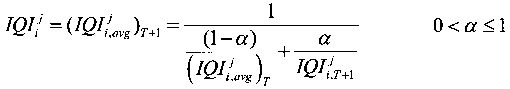
Formula (16)
- 移動端末装置において、下りリンク参照信号を用いてチャネル推定する工程と、得られたチャネル推定値を用いてPMI(Precoding Matrix Indicator)を選択する工程と、少なくとも前記チャネル推定値及び前記PMIを用いてIQI(Interference Quality Indicator)を測定する工程と、少なくとも前記PMI及び前記IQIを無線基地局装置に送信する工程と、
前記無線基地局装置において、前記PMI及び前記IQIを用いてプリコーディングウェイトを生成する工程と、前記プリコーディングウェイトを用いたMIMO伝送を利用して協調マルチポイント送信する工程と、を具備することを特徴とする無線通信方法。 In the mobile terminal apparatus, a step of channel estimation using a downlink reference signal, a step of selecting a PMI (Precoding Matrix Indicator) using the obtained channel estimation value, and at least using the channel estimation value and the PMI A step of measuring IQI (Interference Quality Indicator), a step of transmitting at least the PMI and the IQI to a radio base station device,
The radio base station apparatus includes a step of generating a precoding weight using the PMI and the IQI, and a step of performing cooperative multipoint transmission using MIMO transmission using the precoding weight. A wireless communication method. - 少なくとも各無線基地局装置の平均送信電力及び移動端末装置側の量子化誤差を用いてIQIを求めることを特徴とする請求項12記載の無線通信方法。 13. The radio communication method according to claim 12, wherein IQI is obtained using at least the average transmission power of each radio base station apparatus and the quantization error on the mobile terminal apparatus side.
- 下記式(5)を用いてIQIを求めることを特徴とする請求項12記載の無線通信方法。
式(5)
Hi j:下りリンクのチャネル状態
Fi j:移動端末装置iからのPMIフィードバック
Pavg,j:無線基地局装置jの平均総送信電力
ICIi:移動端末装置iでのCoMPセットに属するセルからの干渉を除く干渉
Ni:移動端末装置iの受信機における平均ノイズ 13. The wireless communication method according to claim 12, wherein IQI is obtained using the following equation (5).
Formula (5)
H i j : Channel state of downlink F i j : PMI feedback from mobile terminal apparatus i Pavg , j : Average total transmission power of radio base station apparatus j ICI i : Cell belonging to CoMP set in mobile terminal apparatus i Interference excluding interference from N i : Average noise at receiver of mobile terminal device i - 下記式(9)を用いてIQIを求めることを特徴とする請求項12記載の無線通信方法。
式(9)
Hi j:下りリンクのチャネル状態
Fi j:移動端末装置iからのPMIフィードバック
Pavg,j:無線基地局装置jの平均総送信電力
ICIi:移動端末装置iでのCoMPセットに属するセルからの干渉を除く干渉
Ni:移動端末装置iの受信機における平均ノイズ 13. The wireless communication method according to claim 12, wherein IQI is obtained using the following equation (9).
Formula (9)
H i j : Channel state of downlink F i j : PMI feedback from mobile terminal apparatus i Pavg , j : Average total transmission power of radio base station apparatus j ICI i : Cell belonging to CoMP set in mobile terminal apparatus i Interference excluding interference from N i : Average noise at receiver of mobile terminal device i - 下記式(10)を用いてIQIを求めることを特徴とする請求項12記載の無線通信方法。
式(10)
Hi j:下りリンクのチャネル状態
Fi j:移動端末装置iからのPMIフィードバック
Pavg,j:無線基地局装置jの平均総送信電力
ICIi:移動端末装置iでのCoMPセットに属するセルからの干渉を除く干渉
Ni:移動端末装置iの受信機における平均ノイズ 13. The wireless communication method according to claim 12, wherein IQI is obtained using the following formula (10).
Formula (10)
H i j : Channel state of downlink F i j : PMI feedback from mobile terminal apparatus i Pavg , j : Average total transmission power of radio base station apparatus j ICI i : Cell belonging to CoMP set in mobile terminal apparatus i Interference excluding interference from N i : Average noise at receiver of mobile terminal device i - 移動端末装置において、下りリンク参照信号を用いてチャネル推定する工程と、得られたチャネル推定値を用いてPMI(Precoding Matrix Indicator)を選択する工程と、少なくとも前記チャネル推定値及び前記PMIを用いてIQI(Interference Quality Indicator)を測定する工程と、少なくとも前記PMI及び前記IQIを無線基地局装置に送信する工程と、
前記無線基地局装置において、協調クラスタ内に含まれる各無線基地局装置にフィードバックされた前記PMI及びIQIを無線基地局装置間で交換する工程と、協調クラスタ内の各無線基地局装置にある自基地局及び協調基地局のPMI及びIQIを用いてプリコーディングウェイトを生成する工程と、前記プリコーディングウェイトを用いたMIMO伝送を利用して協調マルチポイント送信する工程と、を具備することを特徴とする無線通信方法。 In the mobile terminal apparatus, a step of channel estimation using a downlink reference signal, a step of selecting a PMI (Precoding Matrix Indicator) using the obtained channel estimation value, and at least using the channel estimation value and the PMI A step of measuring IQI (Interference Quality Indicator), a step of transmitting at least the PMI and the IQI to a radio base station device,
In the radio base station apparatus, a step of exchanging the PMI and IQI fed back to each radio base station apparatus included in the cooperative cluster between the radio base station apparatuses, and a self-existence in each radio base station apparatus in the cooperative cluster. A step of generating a precoding weight using PMI and IQI of the base station and the cooperative base station, and a step of performing cooperative multipoint transmission using MIMO transmission using the precoding weight, Wireless communication method.
Priority Applications (2)
| Application Number | Priority Date | Filing Date | Title |
|---|---|---|---|
| EP12754930.1A EP2683093B1 (en) | 2011-03-04 | 2012-02-21 | Mobile terminal device, wireless base station and wireless communication method |
| US14/002,925 US9385794B2 (en) | 2011-03-04 | 2012-02-21 | Mobile terminal apparatus, radio base station apparatus and radio communication method |
Applications Claiming Priority (2)
| Application Number | Priority Date | Filing Date | Title |
|---|---|---|---|
| JP2011047972A JP5346970B2 (en) | 2011-03-04 | 2011-03-04 | Mobile terminal apparatus, radio base station apparatus, and radio communication method |
| JP2011-047972 | 2011-03-04 |
Publications (1)
| Publication Number | Publication Date |
|---|---|
| WO2012121008A1 true WO2012121008A1 (en) | 2012-09-13 |
Family
ID=46797977
Family Applications (1)
| Application Number | Title | Priority Date | Filing Date |
|---|---|---|---|
| PCT/JP2012/054174 WO2012121008A1 (en) | 2011-03-04 | 2012-02-21 | Mobile terminal device, wireless base station and wireless communication method |
Country Status (4)
| Country | Link |
|---|---|
| US (1) | US9385794B2 (en) |
| EP (1) | EP2683093B1 (en) |
| JP (1) | JP5346970B2 (en) |
| WO (1) | WO2012121008A1 (en) |
Families Citing this family (10)
| Publication number | Priority date | Publication date | Assignee | Title |
|---|---|---|---|---|
| US9137818B2 (en) * | 2011-12-14 | 2015-09-15 | Alcatel Lucent | Method and system for a reduced-complexity scheduling for a network MIMO with linear zero-forcing beamforming |
| CN103580789B (en) * | 2012-07-30 | 2018-08-10 | 中兴通讯股份有限公司 | Coordinated multipoint transmission recoding processing method, apparatus and system |
| KR102235686B1 (en) | 2013-12-30 | 2021-04-06 | 한국전자통신연구원 | Method for eliminating signal interference based on multiple input multiple output |
| US20170149480A1 (en) * | 2014-07-25 | 2017-05-25 | Ntt Docomo, Inc. | Base station, user equipment, and radio communication network |
| US10056926B2 (en) * | 2014-11-20 | 2018-08-21 | Lg Electronics Inc. | Method and device for transmitting and receiving inter-cell information for cancelling inter-cell interference |
| US10116601B2 (en) * | 2015-02-06 | 2018-10-30 | Jamdeo Canada Ltd. | Methods and devices for display device notifications |
| EP3497811A1 (en) | 2016-08-10 | 2019-06-19 | IDAC Holdings, Inc. | Methods, apparatus, systems and procedures for uplink (ul) channel reciprocity |
| US10609714B2 (en) | 2017-07-12 | 2020-03-31 | Qualcomm Incorporated | Spatial listen before talk |
| US11152994B1 (en) * | 2020-05-27 | 2021-10-19 | Apple Inc. | Communication of channel state information (CSI) in wireless networks |
| CN115529066A (en) * | 2021-06-25 | 2022-12-27 | 华为技术有限公司 | Pre-coding weight calculation method and related device |
Citations (3)
| Publication number | Priority date | Publication date | Assignee | Title |
|---|---|---|---|---|
| JP2002238073A (en) * | 2001-02-09 | 2002-08-23 | Ntt Docomo Inc | Call reception controller and base station |
| WO2010140298A1 (en) * | 2009-06-02 | 2010-12-09 | パナソニック株式会社 | Wireless communication apparatus and wireless communication method |
| JP2011035912A (en) * | 2009-08-05 | 2011-02-17 | Ntt Docomo Inc | Method and base station for obtaining channel quality indicator information |
Family Cites Families (12)
| Publication number | Priority date | Publication date | Assignee | Title |
|---|---|---|---|---|
| US8150412B2 (en) * | 2006-03-06 | 2012-04-03 | Alcatel Lucent | Interference mitigation in a wireless communication system |
| KR20080073196A (en) * | 2007-02-05 | 2008-08-08 | 엘지전자 주식회사 | Method for efficiently transmitting channel quality information in mimo system |
| US8179775B2 (en) * | 2007-08-14 | 2012-05-15 | Texas Instruments Incorporated | Precoding matrix feedback processes, circuits and systems |
| US8463191B2 (en) * | 2009-04-02 | 2013-06-11 | Qualcomm Incorporated | Beamforming options with partial channel knowledge |
| JP4965741B2 (en) * | 2009-04-24 | 2012-07-04 | シャープ株式会社 | Wireless communication system, mobile station apparatus, base station apparatus, communication method, and recording medium |
| JP5205330B2 (en) * | 2009-04-27 | 2013-06-05 | 株式会社日立製作所 | Wireless communication system, wireless communication method, and base station apparatus |
| US8219128B2 (en) * | 2009-06-12 | 2012-07-10 | Telefonaktiebolaget L M Ericsson (Publ) | Network-centric link adaptation for coordinated multipoint downlink transmission |
| AU2010261112B2 (en) * | 2009-06-18 | 2014-06-26 | Sharp Kabushiki Kaisha | Mobile communication system, base station apparatus, mobile station apparatus and mobile communication method |
| US8711716B2 (en) * | 2009-06-19 | 2014-04-29 | Texas Instruments Incorporated | Multiple CQI feedback for cellular networks |
| KR101590198B1 (en) * | 2009-07-30 | 2016-02-15 | 엘지전자 주식회사 | Method of multi cell cooperation in wireless communication system |
| US8594688B2 (en) * | 2009-12-09 | 2013-11-26 | Qualcomm Incorporated | Method and system for rate prediction in coordinated multi-point transmission |
| US8675558B2 (en) * | 2011-01-07 | 2014-03-18 | Intel Corporation | CQI definition for transmission mode 9 in LTE-advanced |
-
2011
- 2011-03-04 JP JP2011047972A patent/JP5346970B2/en not_active Expired - Fee Related
-
2012
- 2012-02-21 WO PCT/JP2012/054174 patent/WO2012121008A1/en active Application Filing
- 2012-02-21 EP EP12754930.1A patent/EP2683093B1/en not_active Not-in-force
- 2012-02-21 US US14/002,925 patent/US9385794B2/en not_active Expired - Fee Related
Patent Citations (3)
| Publication number | Priority date | Publication date | Assignee | Title |
|---|---|---|---|---|
| JP2002238073A (en) * | 2001-02-09 | 2002-08-23 | Ntt Docomo Inc | Call reception controller and base station |
| WO2010140298A1 (en) * | 2009-06-02 | 2010-12-09 | パナソニック株式会社 | Wireless communication apparatus and wireless communication method |
| JP2011035912A (en) * | 2009-08-05 | 2011-02-17 | Ntt Docomo Inc | Method and base station for obtaining channel quality indicator information |
Non-Patent Citations (3)
| Title |
|---|
| "Requirements for Evolved UTRA and Evolved UTRAN", 3GPP TR 25.913 |
| M. SADEK ET AL.: "A leakage-based precoding scheme for downlink multi-user MIMO channels", IEEE TRANS. WIRELESS COMMUN, vol. 6, no. 5, May 2007 (2007-05-01), pages 1713 |
| See also references of EP2683093A4 |
Also Published As
| Publication number | Publication date |
|---|---|
| JP5346970B2 (en) | 2013-11-20 |
| JP2012186631A (en) | 2012-09-27 |
| US9385794B2 (en) | 2016-07-05 |
| EP2683093A1 (en) | 2014-01-08 |
| EP2683093A4 (en) | 2014-08-27 |
| US20140003272A1 (en) | 2014-01-02 |
| EP2683093B1 (en) | 2015-10-14 |
Similar Documents
| Publication | Publication Date | Title |
|---|---|---|
| JP5296004B2 (en) | Feedback information transmission method, mobile station apparatus and base station apparatus | |
| JP5346970B2 (en) | Mobile terminal apparatus, radio base station apparatus, and radio communication method | |
| US9124320B2 (en) | Mobile terminal apparatus, radio base station apparatus and radio communication method | |
| US9398590B2 (en) | Mobile terminal device and radio base station apparatus | |
| JP5388356B2 (en) | Precoding weight generation method, mobile station apparatus and base station apparatus | |
| JP5361933B2 (en) | Mobile terminal apparatus, radio base station apparatus, radio communication method, and radio communication system | |
| EP2750435B1 (en) | Wireless communications system, feedback method, user terminal, and wireless base station device | |
| JP5291664B2 (en) | Data transmission method, base station apparatus and mobile station apparatus | |
| US20130182787A1 (en) | Communication control method, base station apparatus and mobile station apparatus | |
| JP2014131201A (en) | Radio base station, user terminal, radio communication method and radio communication system | |
| JP5268983B2 (en) | COMMUNICATION CONTROL METHOD, MOBILE STATION DEVICE, AND BASE STATION DEVICE | |
| JP5396306B2 (en) | Precoding weight generation method and control apparatus | |
| US8964870B2 (en) | Mobile station apparatus and channel information feedback method | |
| Nagata et al. | Interference measurement scheme for CoMP in LTE-advanced downlink | |
| JP6523377B2 (en) | User terminal, wireless base station, and wireless communication method | |
| WO2011155467A1 (en) | Inter-base station cooperative mimo transmission method, and base station device |
Legal Events
| Date | Code | Title | Description |
|---|---|---|---|
| 121 | Ep: the epo has been informed by wipo that ep was designated in this application |
Ref document number: 12754930 Country of ref document: EP Kind code of ref document: A1 |
|
| WWE | Wipo information: entry into national phase |
Ref document number: 14002925 Country of ref document: US |
|
| NENP | Non-entry into the national phase |
Ref country code: DE |
|
| WWE | Wipo information: entry into national phase |
Ref document number: 2012754930 Country of ref document: EP |