WO2012117957A1 - 斜板式モータ - Google Patents
斜板式モータ Download PDFInfo
- Publication number
- WO2012117957A1 WO2012117957A1 PCT/JP2012/054542 JP2012054542W WO2012117957A1 WO 2012117957 A1 WO2012117957 A1 WO 2012117957A1 JP 2012054542 W JP2012054542 W JP 2012054542W WO 2012117957 A1 WO2012117957 A1 WO 2012117957A1
- Authority
- WO
- WIPO (PCT)
- Prior art keywords
- swash plate
- laser
- type motor
- tilting piston
- plate type
- Prior art date
- Legal status (The legal status is an assumption and is not a legal conclusion. Google has not performed a legal analysis and makes no representation as to the accuracy of the status listed.)
- Ceased
Links
Images






Classifications
-
- F—MECHANICAL ENGINEERING; LIGHTING; HEATING; WEAPONS; BLASTING
- F03—MACHINES OR ENGINES FOR LIQUIDS; WIND, SPRING, OR WEIGHT MOTORS; PRODUCING MECHANICAL POWER OR A REACTIVE PROPULSIVE THRUST, NOT OTHERWISE PROVIDED FOR
- F03C—POSITIVE-DISPLACEMENT ENGINES DRIVEN BY LIQUIDS
- F03C1/00—Reciprocating-piston liquid engines
- F03C1/22—Reciprocating-piston liquid engines with movable cylinders or cylinder
- F03C1/24—Reciprocating-piston liquid engines with movable cylinders or cylinder in which the liquid exclusively displaces one or more pistons reciprocating in rotary cylinders
-
- F—MECHANICAL ENGINEERING; LIGHTING; HEATING; WEAPONS; BLASTING
- F01—MACHINES OR ENGINES IN GENERAL; ENGINE PLANTS IN GENERAL; STEAM ENGINES
- F01B—MACHINES OR ENGINES, IN GENERAL OR OF POSITIVE-DISPLACEMENT TYPE, e.g. STEAM ENGINES
- F01B3/00—Reciprocating-piston machines or engines with cylinder axes coaxial with, or parallel or inclined to, main shaft axis
- F01B3/0032—Reciprocating-piston machines or engines with cylinder axes coaxial with, or parallel or inclined to, main shaft axis having rotary cylinder block
- F01B3/0044—Component parts, details, e.g. valves, sealings, lubrication
-
- F—MECHANICAL ENGINEERING; LIGHTING; HEATING; WEAPONS; BLASTING
- F01—MACHINES OR ENGINES IN GENERAL; ENGINE PLANTS IN GENERAL; STEAM ENGINES
- F01B—MACHINES OR ENGINES, IN GENERAL OR OF POSITIVE-DISPLACEMENT TYPE, e.g. STEAM ENGINES
- F01B3/00—Reciprocating-piston machines or engines with cylinder axes coaxial with, or parallel or inclined to, main shaft axis
- F01B3/10—Control of working-fluid admission or discharge peculiar thereto
- F01B3/101—Control of working-fluid admission or discharge peculiar thereto for machines with stationary cylinders
- F01B3/102—Changing the piston stroke by changing the position of the swash plate
-
- F—MECHANICAL ENGINEERING; LIGHTING; HEATING; WEAPONS; BLASTING
- F03—MACHINES OR ENGINES FOR LIQUIDS; WIND, SPRING, OR WEIGHT MOTORS; PRODUCING MECHANICAL POWER OR A REACTIVE PROPULSIVE THRUST, NOT OTHERWISE PROVIDED FOR
- F03C—POSITIVE-DISPLACEMENT ENGINES DRIVEN BY LIQUIDS
- F03C1/00—Reciprocating-piston liquid engines
- F03C1/02—Reciprocating-piston liquid engines with multiple-cylinders, characterised by the number or arrangement of cylinders
- F03C1/06—Reciprocating-piston liquid engines with multiple-cylinders, characterised by the number or arrangement of cylinders with cylinder axes generally coaxial with, or parallel or inclined to, main shaft axis
- F03C1/061—Reciprocating-piston liquid engines with multiple-cylinders, characterised by the number or arrangement of cylinders with cylinder axes generally coaxial with, or parallel or inclined to, main shaft axis having stationary cylinders
- F03C1/0623—Details, component parts
- F03C1/0626—Cylinders
-
- F—MECHANICAL ENGINEERING; LIGHTING; HEATING; WEAPONS; BLASTING
- F05—INDEXING SCHEMES RELATING TO ENGINES OR PUMPS IN VARIOUS SUBCLASSES OF CLASSES F01-F04
- F05C—INDEXING SCHEME RELATING TO MATERIALS, MATERIAL PROPERTIES OR MATERIAL CHARACTERISTICS FOR MACHINES, ENGINES OR PUMPS OTHER THAN NON-POSITIVE-DISPLACEMENT MACHINES OR ENGINES
- F05C2251/00—Material properties
- F05C2251/10—Hardness
Definitions
- the present invention relates to a swash plate type motor including a swash plate that can be tilted between two postures of a low-speed posture and a high-speed posture.
- Patent Document 1 quenches the inner hole portion of the tilting piston cylinder hole into a plurality of annular shapes centering on the axis of the tilting piston cylinder hole using laser light. Is. Thereby, it is said that seizure resistance and wear resistance of the sliding surface of the cylinder hole for the tilting piston can be improved.
- the present invention has been made in view of the above circumstances, and an object thereof is to provide a tilting piston cylinder hole structure capable of improving wear resistance and shortening the time required for quenching work.
- a swash plate motor is provided.
- the present invention includes an output shaft provided rotatably with respect to the main body case, a cylinder block engaged with the output shaft, a piston disposed in each of a plurality of cylinder holes formed in the cylinder block, A swash plate with which the piston abuts, a tilt piston that changes the tilt angle of the swash plate by pressing the swash plate, and a tilt piston that is formed in the body case and holds the tilt piston slidably.
- the tilt piston is tilted by the pressing force from the swash plate in the bottom inner hole portion of the cylinder hole for the tilt piston. Laser-quenched in the local area where the part hits, and the portions other than the opening inner hole part and the bottom inner hole part of the tilting piston cylinder hole are not laser-hardened.
- the bets are swash plate type motor.
- the wear resistance of the tilting piston cylinder hole can be sufficiently enhanced.
- laser quenching is not performed on the tilting piston cylinder hole except for the opening inner hole portion and the bottom inner hole portion, so that the time required for the quenching operation can be shortened.
- laser quenching is performed in the circumferential direction with respect to the bottom inner hole portion, and the laser quenching amount is continuously increased toward the local portion.
- the laser-hardened part expands in a convex shape.
- a discontinuous portion such as a step is hardly formed in the circumferential direction of the bottom inner hole portion, and the cross section of the bottom inner hole portion can be a smooth circle.
- the expansion height of the tilting piston cylinder hole is reduced except for the portion where the tilting piston hits the strongest, it is easy to maintain the fluidity of oil in the sliding direction (axial direction) of the tilting piston and reduce wear. it can.
- a facing portion facing the local portion is not laser-quenched, and a portion other than the facing portion is continuously laser-quenched.
- the facing part that opposes the local part where the end of the tilting piston hits is a place where wear is relatively difficult to occur. According to this configuration, the fluidity of the oil in the sliding direction (axial direction) of the tilting piston can be easily maintained by not expanding the facing portion.
- laser quenching is performed over the entire circumference of the bottom inner hole portion. According to this configuration, wear resistance is enhanced over the entire circumference of the bottom inner hole portion.
- the laser quenching amount is continuously increased toward a plurality of locations including the local portion located at an equal phase difference in the circumferential direction in the bottom inner hole portion.
- convex portions with improved wear resistance at a plurality of locations are formed with equal phase differences in the circumferential direction of the bottom inner hole portion of the tilting piston cylinder hole.
- the tilting piston is stably held by the plurality of convex portions.
- two of the bottom inner hole portions are laser-hardened only in the local portion along the axial direction.
- the end of the tilting piston is always easy to hit the convex part with improved wear resistance.
- the pressing force is reduced by having two convex portions. As a result, the wear resistance is increased.
- two of the bottom inner hole portions are laser-quenched only in the circumferential direction along the circumferential direction.
- This configuration can widen the curing range by laser quenching. As a result, wear resistance is increased.
- laser quenching is further performed over the entire circumference of the opening inner hole portion.
- laser quenching is further performed on a portion of the opening inner hole portion which is in contact with an end portion of the tilting piston located diagonally to the local portion.
- the wear resistance on the opening portion side of the tilting piston cylinder hole is sufficiently enhanced.
- the time required for the quenching operation can be shortened by limiting the locations where laser quenching is performed.
- the pressing force is reduced by providing two convex portions with improved wear resistance.
- the wear resistance on the opening side of the tilting piston cylinder hole is further increased.
- two of the opening inner hole portions are laser-quenched along the circumferential direction only at the portion where the end of the tilting piston hits.
- the hardening range by laser quenching can be widened on the opening side of the tilting piston cylinder hole.
- the wear resistance on the opening side of the tilting piston cylinder hole is further increased.
- the top of the expanded portion by laser hardening is processed to be a flat surface.
- the tilting piston can be held (or moved) more stably in the tilting piston cylinder hole.
- the wear resistance of the tilting piston cylinder hole can be sufficiently increased.
- the laser quenching is not performed on the portions excluding the opening inner hole portion and the bottom inner hole portion, the time required for the quenching operation can be shortened.
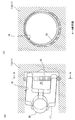
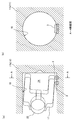
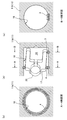
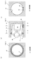
- FIG. 1 is a cutaway sectional view showing a swash plate type motor according to a first embodiment of the present invention. It is the figure which expanded the tilting piston part of FIG. 1, Comprising: It is explanatory drawing which shows the cylinder hole structure for tilting pistons which concerns on 1st Embodiment. It is explanatory drawing which shows the cylinder hole structure for tilting pistons which concerns on 2nd Embodiment. It is explanatory drawing which shows the cylinder hole structure for tilting pistons which concerns on the modification of 2nd Embodiment. It is explanatory drawing which shows the cylinder hole structure for tilting pistons which concerns on the modification of 2nd Embodiment.
- the swash plate motor according to the present embodiment can be applied to, for example, a construction vehicle, but is not limited to a construction vehicle, and the swash plate can be tilted between two postures of a low speed posture and a high speed posture.
- the present invention can be widely applied as a two-speed swash plate motor including a tilting piston and a tilting piston cylinder hole into which the tilting piston is inserted.
- a swash plate type motor 1 shown in FIG. 1 is disposed on a construction vehicle (not shown) and is used for driving a crawler type traveling device.
- the swash plate motor 1 is configured as a variable displacement hydraulic motor that can switch between high speed and low speed, and is connected to a reduction gear unit 10 as shown in FIG.
- a traveling crawler track (not shown) is attached via a sprocket (not shown) attached to the flange portion 10b of the case 10a. It will be rotationally driven.
- the swash plate motor 1 includes a main body case 11, an output shaft 12, a cylinder block 13, a piston 15, a swash plate 16, a tilting piston 17, a tilting piston cylinder hole 18, and the like.
- the main body case 11 includes case blocks 11a and 11b, and a cylinder block 13 and a swash plate 16 are disposed in an internal space 20 formed by combining the case block 11a and the case block 11b. Yes. Moreover, the case 10a of the reduction gear unit 10 is rotatably held by the case block 11a.
- the output shaft 12 is rotatably held with respect to the main body case 11 and is disposed so as to protrude from the internal space 20 toward the reduction gear unit 10.
- the output shaft 12 constitutes the input shaft of the speed reducer unit 10.
- the cylinder block 13 is disposed around the output shaft 12 in the internal space 20, and is fixed to the output shaft 12 by, for example, spline coupling.
- a plurality of cylinder holes 14 are formed in the cylinder block 13 so as to extend in parallel with the output shaft 12.
- the plurality of cylinder holes 14 are formed in the cylinder block 13 so as to be arranged along the circumferential direction thereof.
- the piston 15 is inserted into each of a plurality of cylinder holes 14 provided in the cylinder block 13. Pressure oil supplied from a hydraulic pump (not shown) is supplied to each cylinder hole 14 and discharged, so that each piston 15 inserted into each cylinder hole 14 reciprocates.
- a slope 16a is formed on the swash plate 16, and a plurality of pistons 15 are in contact with the slope 16a.
- a sliding member that is slidably attached to the main body of the piston 15 and that slides on the inclined surface 16 a is attached to a contact portion with the swash plate 16 on the distal end side of the piston 15.
- the swash plate 16 is switched between a low-speed posture and a high-speed posture by operating a tilting piston 17 described later.
- a tilting piston 17 described later.
- FIG. 1 when the swash plate 16 is in a low-speed posture, the amount of pressure oil introduced into the cylinder hole 14 at a position where the piston 15 protrudes most from the cylinder hole 14 of the cylinder block 13 is high. Since there are more than in the case of the posture (since the cylinder volume is large), it rotates at a low speed by a predetermined flow rate of pressure oil supplied from a hydraulic pump (not shown).
- inclination of the swash plate 16 slope 16a
- the amount of pressurized oil introduced into the cylinder hole 14 at the position where the piston 15 protrudes most from the cylinder hole 14 of the cylinder block 13 is smaller than that in the low-speed posture (the cylinder volume is small). Therefore, it is rotated at a high speed by a predetermined amount of pressure oil supplied from a hydraulic pump (not shown).
- a tilt piston cylinder hole 18 is provided in the case block 11 b of the main body case 11.
- the tilt piston 17 is inserted into the tilt piston cylinder hole 18.
- the tilting piston 17 is a piston for pushing the end of the swash plate 16 and changing the tilting angle of the swash plate 16, and is formed in a cylindrical shape.
- a recess is formed at one end of the tilting piston 17, and a back pressure chamber into which pressure oil for operating the tilting piston 17 is introduced between the recess and the bottom surface side of the tilting piston cylinder hole 18. 24 is formed.
- a coil spring 23 is disposed in the back pressure chamber 24.
- a ball-like swinging portion 22 that is swingably supported with respect to the tilting piston 17 is provided at the other end of the tilting piston 17.
- a contact portion 21 that contacts the swash plate 16 on the side opposite to the inclined surface 16a is attached to the swing portion 22 by welding or the like.
- the contact portion 21 is always pressed against the swash plate 16 by a coil spring 23.
- the swinging part 22 may be fixed to the tilting piston 17 and the contact part 21 may be omitted.
- the pressure oil to the back pressure chamber 24 for operating the tilting piston 17 is supplied through the oil passages 26a, 26b, and 26c.
- the second speed switching valve 27 is in the state shown in FIG. 1, the upstream oil passage 26a and the downstream oil passage 26b to which pressure oil is supplied are blocked, so that the pressure oil is back pressure.
- the tilting piston 17 is in the state shown in FIG. That is, at this time, the tilting piston 17 is in a state of being retracted to the back side of the tilting piston cylinder hole 18 so that the swash plate 16 assumes a low-speed posture.
- the tilting piston 17 When the tilting piston 17 is retracted toward the inner side of the tilting piston cylinder hole 18, the tilting piston 17 can be retracted to a position where it does not protrude from the opening edge of the tilting piston cylinder hole 18.
- a pilot pressure switching valve (not shown) is switched and pilot pressure oil is introduced into the pilot pressure port 28, the 2-speed switching valve 27 is energized by the pilot pressure, and the notch 27a in the 2-speed switching valve 27a is activated.
- the oil passage 26a and the oil passage 26b are connected so as to communicate with each other.
- the pressure oil is introduced into the back pressure chamber 24 through the oil passages 26a, 26b, and 26c, and the tilting piston 17 is biased, so that the tilting piston 17 moves toward the opening side of the tilting piston cylinder hole 18. Therefore, the swash plate 16 can be switched to a high-speed posture.
- the tilting piston 17 can tilt the swash plate 16 between two postures of the low-speed posture and the high-speed posture.
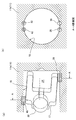
- FIG. 2B is a cross-sectional view taken along the line AA in FIG.
- illustration of the coil spring 23 and the contact portion 21 is omitted.
- illustration of components such as the tilting piston 17 is omitted, and only the tilting piston cylinder hole 18 is shown (the same applies to the drawings after FIG. 3).
- the material of the case block 11b (main body case 11) is cast iron.
- the tilting piston 17 tilts the swash plate 16 by pushing the end of the swash plate 16. That is, as shown in FIG. 2A, the tilting piston 17 is tilted with respect to the central axis of the tilting piston cylinder hole 18 by the pressing force from the swash plate 16.
- the tilting piston 17 indicated by a solid line is when the swash plate 16 is in a high-speed posture, and the two-dot chain line is when the swash plate 16 is in a low-speed posture.
- the tilting piston 17 is tilted by the pressing force from the swash plate 16, so that laser quenching is applied to a local portion where the end of the tilting piston 17 hits.
- Laser hardening is a hardening method in which the surface of a component is irradiated and hardened by irradiating a laser beam with a high energy density.
- the laser irradiation apparatus include a carbon dioxide laser, a solid-state laser (YAG laser), and a semiconductor laser.
- the hardening part 3 which gave laser hardening expands in convex shape.
- only one portion along the circumferential direction of the tilting piston cylinder hole 18 is laser-quenched only to a local portion where the end of the tilting piston 17 hits the inner hole portion of the bottom portion of the tilting piston cylinder hole 18.
- laser quenching is performed for a short distance in a circular arc shape only at the local portion where the end of the tilting piston 17 hits at a constant laser output wattage and constant scanning (irradiation) speed.
- the portion other than the local portion where the end of the tilting piston 17 hits on the back side (bottom side) is not laser-hardened.
- laser quenching is performed on the portion (local part) of the tilting piston cylinder hole 18 where the tilting piston 17 strikes most strongly, and this portion is hardened. Abrasion resistance can be sufficiently increased.
- the portion of the tilting piston cylinder hole 18 other than this portion (local portion) is not laser-quenched, so that the time required for the quenching operation can be shortened.
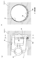
- FIG. 3B is a cross-sectional view taken along the line AA in FIG.
- laser quenching is applied to the local portion of the bottom inner hole portion of the tilting piston cylinder hole 18 where the end of the tilting piston 17 hits. Yes. Also in this embodiment, one laser quenching is performed in the circumferential direction of the bottom inner hole portion of the tilting piston cylinder hole 18.
- the laser quenching amount is continuously increased toward the portion (local portion) where the end of the tilting piston 17 hits.
- the facing portion facing the portion (local portion) where the end of the tilting piston 17 hits is not laser-quenched, and the facing portion is Laser quenching is continuously applied to the removed portion in the circumferential direction.
- the laser output wattage is changed from zero to a predetermined wattage, and then predetermined.
- the expansion amount by laser hardening is continuous. Inclined.
- the tilt piston cylinder is changed by changing the output wattage at a constant laser scanning speed so that the inner surface of the quenching portion 32 is close to a perfect circle.
- Laser hardening is applied to the inner surface of the hole 18 in the circumferential direction.
- the output wattage of the laser is set to a predetermined wattage (maximum value) at the portion (local part) where the end of the tilting piston 17 hits.
- the cross section of the bottom inner hole portion may be a smooth circle. It can. Further, since the expansion height of the tilting piston cylinder hole 18 other than the portion where the tilting piston 17 is the strongest is lowered, the fluidity of the oil in the sliding direction (axial direction) of the tilting piston 17 can be easily maintained. Wear can be reduced.
- the facing portion that opposes the local portion against which the end of the tilting piston 17 hits is a place where wear is relatively difficult to occur.
- the fluidity of the oil in the sliding direction (axial direction) of the tilting piston 17 can be easily maintained by not expanding the facing portion.
- FIG. 4B is a cross-sectional view taken along the line AA in FIG.
- the laser output wattage is set to zero, and a portion where no quenching is performed is provided.
- the minimum value of the laser output wattage is not zero. That is, the cylinder for the tilting piston is made while continuously increasing the laser quenching amount toward the portion (local part) where the end of the tilting piston 17 abuts so that the inner surface of the quenching portion 33 is close to a perfect circle. Laser hardening is performed over the entire circumference of the hole 18. Thereby, abrasion resistance can be improved over the perimeter of the bottom inner hole part which the edge part of the inclination piston 17 contacts.
- FIG. 5B is a cross-sectional view taken along the line AA in FIG.
- laser quenching is performed once in the circumferential direction with respect to the bottom inner hole portion where the end of the tilting piston 17 hits.
- the laser output is increased or decreased three times during one round of laser hardening.
- the laser scans once from the facing portion 18a facing the portion (local portion) where the end of the tilting piston 17 hits.
- the laser scanning speed is constant and the output wattage is continuously inclined.
- the output wattage of the laser is continuously increased from zero to a predetermined wattage (local portion where the end of the tilting piston 17 hits) between the facing portion 18a and the portion 18b and thereafter from the predetermined wattage to zero.
- the output wattage of the laser is controlled with a slope.
- the laser output wattage is controlled between the portion 18b and the portion 18c and between the portion 18c and the facing portion 18a in the same manner as between the facing portion 18a and the portion 18b.
- the laser is directed toward three locations including the local portion (portion where the end portion of the tilting piston 17 hits) at the position of the equal phase difference in the circumferential direction in the bottom inner hole portion of the tilting piston cylinder hole 18.
- a quenching portion 34 having a continuously increased quenching amount is formed.
- the convex portions 34a higher than the periphery where the wear resistance is improved at three locations with an equal phase difference in the circumferential direction of the bottom inner hole portion of the tilting piston cylinder hole 18 are formed.
- the tilting piston 17 is stably held by these convex portions 34a.
- the convex-shaped part 34a higher than the periphery where abrasion resistance was improved is not restricted to three places.
- the hardening part 34 of this embodiment can also be formed by changing the scanning speed with constant output wattage of the laser.
- the scanning speed of the part is made slower than the other parts. Even in this case, the number of laser scans can be set to one (one round scan), and the processing time can be shortened.
- the laser output wattage is constant, and a portion higher than the surroundings can be formed by changing the scanning speed.
- FIG. 6B is a cross-sectional view taken along the line AA in FIG.
- two lasers are provided along the axial direction of the tilting piston cylinder hole 18 only in the portion where the end of the tilting piston 17 hits the bottom inner hole portion of the tilting piston cylinder hole 18. Quenched.
- the end portion of the tilting piston 17 is always easy to hit the quenching portion 35 with improved wear resistance. Moreover, since the convex hardening part 35 becomes two places, pressing force reduces and abrasion resistance improves. Moreover, after forming one quenching part 35, it is necessary to cool this quenching part 35 sufficiently, and then to form the other quenching part 35. However, since the number of the quenching parts 35 is small, the total amount of quenching work is required. You can save time.
- FIG. 7B is a cross-sectional view taken along the line AA in FIG.
- two lasers are provided along the circumferential direction of the tilting piston cylinder hole 18 only in the portion where the end of the tilting piston 17 abuts against the bottom inner hole portion of the tilting piston cylinder hole 18. Quenching is performed (quenching part 3).
- FIGS. 8B and 8C are an AA sectional view and a BB sectional view of FIG. 8A, respectively.
- laser quenching is performed not only on the bottom inner hole portion of the tilting piston cylinder hole 18 but also on the opening inner hole portion. As shown in FIG. 8 with reference numeral 4 attached to the quenching portion, the laser output over the entire circumference of the opening inner hole portion of the tilting piston cylinder hole 18 where the end of the tilting piston 17 abuts on the opening side.
- One laser quenching is performed at a constant wattage and a constant scanning speed. Of the tilting piston cylinder hole 18, the portions other than the opening inner hole portion and the bottom inner hole portion are not laser-quenched.
- the leakage of oil is reduced by the annular quenching portion 4 formed over the entire circumference of the opening inner hole portion of the tilting piston cylinder hole 18, and the lubricity of the tilting piston cylinder hole 18 is improved. To do. Further, wear resistance is enhanced over the entire circumference of the opening inner hole portion.
- FIG. 9B and FIG. 9C are an AA sectional view and a BB sectional view of FIG. 9A, respectively.
- laser quenching is performed in the circumferential direction on the bottom inner hole portion of the tilting piston cylinder hole 18, but in this embodiment, in the bottom portion of the tilting piston cylinder hole 18.
- Two laser quenching is performed on the hole portion along the axial direction of the tilting piston cylinder hole 18 (quenching portion 35).
- the fluidity of the oil on the bottom side of the tilting piston cylinder hole 18 is higher than that of the embodiment shown in FIG. 8, so that the lubricity of the tilting piston cylinder hole 18 is further improved.
- FIG. 10B is a cross-sectional view taken along the line AA in FIG.
- laser quenching is further applied to the portion of the opening inner hole portion of the tilting piston cylinder hole 18 where the end of the tilting piston 17 located diagonally to the quenching portion 3 hits ( Quenching part 42). Similarly to the bottom inner hole portion, only the portion where the end portion of the tilting piston 17 hits the opening inner hole portion is subjected to laser hardening along the circumferential direction of the tilting piston cylinder hole 18.
- the quenching portion 42 by forming the quenching portion 42 in the portion of the opening inner hole where the tilting piston 17 strongly hits, the wear resistance on the opening side of the tilting piston cylinder hole 18 is sufficiently enhanced. Can do.
- the time required for the quenching operation can be shortened by limiting the locations where laser quenching is performed as in the present embodiment.
- FIG. 11B is a cross-sectional view taken along the line AA in FIG.
- two laser quenching along the axial direction is performed only on the portion where the end portion of the tilting piston 17 hits against the opening inner hole portion and the bottom inner hole portion of the tilting piston cylinder hole 18. Has been given.
- the convex hardened portions (35, 43) with improved wear resistance are provided at two locations, respectively, so that the pressing force is reduced in both the bottom inner hole portion and the opening inner hole portion. Wear resistance is improved.
- FIG. 12B is a cross-sectional view taken along line AA in FIG.
- two laser quenching along the circumferential direction is performed only on the portion where the end portion of the tilting piston 17 hits the opening inner hole portion and the bottom inner hole portion of the tilting piston cylinder hole 18.
- the hardening range by laser hardening can be widened also on the opening side of the tilting piston cylinder hole 18.
- FIG. 13B is a cross-sectional view taken along the line AA in FIG.
- the top of the quenching portion 36 expanded by laser quenching is processed into a flat surface 36a.
- processing methods there are methods such as cutting by machining and crushing the top.
- the holding (or movement) of the tilting piston 17 in the tilting piston cylinder hole 18 is more stable.
- the shape of the top of the quenching portion processed into a flat surface is not limited to the second embodiment shown in FIG. 3, but is also a cylinder hole for tilting pistons according to all the embodiments of FIGS. 2 and 4 to 12. Can be applied to the structure.
- swash plate motor 11 body case 12: output shaft 13: cylinder block 14: cylinder hole 15: piston 16: swash plate 17: tilting piston 18: cylinder hole for tilting piston
Landscapes
- Engineering & Computer Science (AREA)
- Mechanical Engineering (AREA)
- General Engineering & Computer Science (AREA)
- Chemical & Material Sciences (AREA)
- Combustion & Propulsion (AREA)
- Reciprocating Pumps (AREA)
- Hydraulic Motors (AREA)
Abstract
Description
図1に示す斜板式モータ1は、図示しない建設車両に配設され、クローラ式の走行装置の駆動用に用いられる。この斜板式モータ1は、高速と低速との2速切換を可能とする可変容量型の油圧モータとして構成され、図1に示すように減速機ユニット10と連結される。斜板式モータ1から回転が伝達された減速機ユニット10のケース10aが最終的に回転駆動されることで、ケース10aのフランジ部10bに取り付けられた図示しないスプロケットを介して図示しない走行用履帯が回転駆動されることになる。
斜板式モータ1の構成は上記した通りである。次に、斜板式モータ1を構成する本体ケース11のケースブロック11bに形成された傾転ピストン用シリンダ孔18の構造について図2を参照しつつ説明する。なお、図2(b)は、図2(a)のA-A断面図である。図2(a)においては、コイルばね23、当接部21の図示を省略している。図2(b)においては、傾転ピストン17などの部品の図示を省略し、傾転ピストン用シリンダ孔18のみを示している(図3以降の図についても同様)。ケースブロック11b(本体ケース11)の材質は、鋳鉄である。
次に、図3を参照しつつ、第2実施形態に係る傾転ピストン用シリンダ孔構造について説明する。図3(b)は、図3(a)のA-A断面図である。
次に、図4を参照しつつ、第2実施形態の変形例に係る傾転ピストン用シリンダ孔構造について説明する。図4(b)は、図4(a)のA-A断面図である。
次に、図5を参照しつつ、第2実施形態の変形例に係る傾転ピストン用シリンダ孔構造について説明する。図5(b)は、図5(a)のA-A断面図である。
次に、図6を参照しつつ、第3実施形態に係る傾転ピストン用シリンダ孔構造について説明する。図6(b)は、図6(a)のA-A断面図である。
次に、図7を参照しつつ、第3実施形態の変形例に係る傾転ピストン用シリンダ孔構造について説明する。図7(b)は、図7(a)のA-A断面図である。
次に、図8を参照しつつ、第4実施形態に係る傾転ピストン用シリンダ孔構造について説明する。図8(b)および図8(c)は、それぞれ、図8(a)のA-A断面図およびB-B断面図である。
次に、図9を参照しつつ、第4実施形態の変形例に係る傾転ピストン用シリンダ孔構造について説明する。図9(b)および図9(c)は、それぞれ、図9(a)のA-A断面図およびB-B断面図である。
次に、図10を参照しつつ、第5実施形態に係る傾転ピストン用シリンダ孔構造について説明する。図10(b)は、図10(a)のA-A断面図である。
次に、図11を参照しつつ、第5実施形態の変形例に係る傾転ピストン用シリンダ孔構造について説明する。図11(b)は、図11(a)のA-A断面図である。
次に、図12を参照しつつ、第5実施形態の変形例に係る傾転ピストン用シリンダ孔構造について説明する。図12(b)は、図12(a)のA-A断面図である。
最後に、図13を参照しつつ、図3に示した第2実施形態の変形例に係る傾転ピストン用シリンダ孔構造について説明する。図13(b)は、図13(a)のA-A断面図である。
11:本体ケース
12:出力軸
13:シリンダブロック
14:シリンダ孔
15:ピストン
16:斜板
17:傾転ピストン
18:傾転ピストン用シリンダ孔
Claims (12)
- 本体ケースに対して回転自在に設けられた出力軸と、
前記出力軸に係合するシリンダブロックと、
前記シリンダブロックに形成された複数のシリンダ孔のそれぞれに配置されたピストンと、
前記ピストンが当接する斜板と、
前記斜板を押して当該斜板の傾転角度を変更する傾転ピストンと、
前記本体ケースに形成され、前記傾転ピストンを摺動自在に保持する傾転ピストン用シリンダ孔と、
を備えた斜板式モータにおいて、
前記傾転ピストン用シリンダ孔の底部内孔部分のうち、前記斜板からの押圧力により前記傾転ピストンが傾くことで当該傾転ピストンの端部が当たる局部にレーザ焼入れされており、
前記傾転ピストン用シリンダ孔のうち、開口部内孔部分および前記底部内孔部分、を除く部分はレーザ焼入れされていないことを特徴とする、斜板式モータ。 - 請求項1に記載の斜板式モータにおいて、
前記底部内孔部分に対して周方向にレーザ焼入れされており、
前記局部に向かってレーザ焼入れ量が連続的に増やされていることを特徴とする、斜板式モータ。 - 請求項2に記載の斜板式モータにおいて、
前記底部内孔部分のうち、前記局部と対向する対向部分はレーザ焼入れされておらず、当該対向部分を除く部分が連続的にレーザ焼入れされていることを特徴とする、斜板式モータ。 - 請求項2に記載の斜板式モータにおいて、
前記底部内孔部分の全周にわたってレーザ焼入れされていることを特徴とする、斜板式モータ。 - 請求項3または4に記載の斜板式モータにおいて、
前記底部内孔部分において周方向に等位相差の位置にある前記局部を含む複数箇所に向かってレーザ焼入れ量が連続的に増やされていることを特徴とする、斜板式モータ。 - 請求項1に記載の斜板式モータにおいて、
前記底部内孔部分に関しては、前記局部のみに軸方向に沿って2本、レーザ焼入れされていることを特徴とする、斜板式モータ。 - 請求項1に記載の斜板式モータにおいて、
前記底部内孔部分に関しては、前記局部のみに周方向に沿って2本、レーザ焼入れされていることを特徴とする、斜板式モータ。 - 請求項1~7のいずれかに記載の斜板式モータにおいて、
前記開口部内孔部分の全周にわたって、さらにレーザ焼入れされていることを特徴とする、斜板式モータ。 - 請求項1~7のいずれかに記載の斜板式モータにおいて、
前記開口部内孔部分のうち前記局部と対角に位置する前記傾転ピストンの端部が当たる部分に、さらにレーザ焼入れされていることを特徴とする、斜板式モータ。 - 請求項9に記載の斜板式モータにおいて、
前記開口部内孔部分に関しては、前記傾転ピストンの端部が当たる部分のみに、軸方向に沿って2本、レーザ焼入れされていることを特徴とする、斜板式モータ。 - 請求項9に記載の斜板式モータにおいて、
前記開口部内孔部分に関しては、前記傾転ピストンの端部が当たる部分のみに、周方向に沿って2本、レーザ焼入れされていることを特徴とする、斜板式モータ。 - 請求項1~11のいずれかに記載の斜板式モータにおいて、
レーザ焼入れによる膨張部位の頂部が加工されて平面とされていることを特徴とする、斜板式モータ。
Priority Applications (4)
| Application Number | Priority Date | Filing Date | Title |
|---|---|---|---|
| DE112012001019T DE112012001019T5 (de) | 2011-02-28 | 2012-02-24 | Taumelscheibenmotor |
| US14/001,275 US20130340605A1 (en) | 2011-02-28 | 2012-02-24 | Swash plate-type motor |
| CN201280010730.9A CN103384763B (zh) | 2011-02-28 | 2012-02-24 | 斜板式马达 |
| KR1020137025401A KR101790383B1 (ko) | 2011-02-28 | 2012-02-24 | 사판식 모터 |
Applications Claiming Priority (2)
| Application Number | Priority Date | Filing Date | Title |
|---|---|---|---|
| JP2011041153A JP5590732B2 (ja) | 2011-02-28 | 2011-02-28 | 斜板式モータ |
| JP2011-041153 | 2011-02-28 |
Publications (1)
| Publication Number | Publication Date |
|---|---|
| WO2012117957A1 true WO2012117957A1 (ja) | 2012-09-07 |
Family
ID=46757894
Family Applications (1)
| Application Number | Title | Priority Date | Filing Date |
|---|---|---|---|
| PCT/JP2012/054542 Ceased WO2012117957A1 (ja) | 2011-02-28 | 2012-02-24 | 斜板式モータ |
Country Status (6)
| Country | Link |
|---|---|
| US (1) | US20130340605A1 (ja) |
| JP (1) | JP5590732B2 (ja) |
| KR (1) | KR101790383B1 (ja) |
| CN (1) | CN103384763B (ja) |
| DE (1) | DE112012001019T5 (ja) |
| WO (1) | WO2012117957A1 (ja) |
Families Citing this family (2)
| Publication number | Priority date | Publication date | Assignee | Title |
|---|---|---|---|---|
| JP6253318B2 (ja) * | 2013-09-06 | 2017-12-27 | ナブテスコ株式会社 | 斜板式モータまたは斜板式ポンプ |
| DE102023201689A1 (de) * | 2023-02-24 | 2024-08-29 | Robert Bosch Gesellschaft mit beschränkter Haftung | Schwenkwiegenlagerung, Verfahren zum Herstellen einer Schwenkwiegenlagerung und Kolbenmaschine |
Citations (3)
| Publication number | Priority date | Publication date | Assignee | Title |
|---|---|---|---|---|
| JPS59126167A (ja) * | 1982-12-29 | 1984-07-20 | Yanmar Diesel Engine Co Ltd | レ−ザ焼入シリンダ |
| WO2010007710A1 (ja) * | 2008-07-16 | 2010-01-21 | 株式会社カワサキプレシジョンマシナリ | 斜板式液圧回転機 |
| JP4481863B2 (ja) * | 2005-04-12 | 2010-06-16 | 日立建機株式会社 | 液圧回転機用のシリンダブロック |
Family Cites Families (5)
| Publication number | Priority date | Publication date | Assignee | Title |
|---|---|---|---|---|
| US3476020A (en) * | 1968-09-03 | 1969-11-04 | Caterpillar Tractor Co | Engine block with case hardening of cylinder walls |
| JPS6176223A (ja) * | 1984-09-19 | 1986-04-18 | Daihatsu Motor Co Ltd | 内燃機関におけるシリンダボアの内径仕上げ加工方法 |
| US5827588A (en) * | 1996-11-18 | 1998-10-27 | Ingersoll-Rand Company | Workpiece having a laser heat-treated surface formed by a small diameter bore extending in workpiece |
| US8118567B2 (en) * | 2006-12-15 | 2012-02-21 | Kabushiki Kaisha Kawasaki Precision Machinery | Swash plate type piston pump motor |
| JP4829159B2 (ja) * | 2007-03-29 | 2011-12-07 | 川崎重工業株式会社 | 斜板式ピストンポンプ・モータ及びその製造方法 |
-
2011
- 2011-02-28 JP JP2011041153A patent/JP5590732B2/ja not_active Expired - Fee Related
-
2012
- 2012-02-24 WO PCT/JP2012/054542 patent/WO2012117957A1/ja not_active Ceased
- 2012-02-24 DE DE112012001019T patent/DE112012001019T5/de active Pending
- 2012-02-24 KR KR1020137025401A patent/KR101790383B1/ko active Active
- 2012-02-24 CN CN201280010730.9A patent/CN103384763B/zh active Active
- 2012-02-24 US US14/001,275 patent/US20130340605A1/en not_active Abandoned
Patent Citations (3)
| Publication number | Priority date | Publication date | Assignee | Title |
|---|---|---|---|---|
| JPS59126167A (ja) * | 1982-12-29 | 1984-07-20 | Yanmar Diesel Engine Co Ltd | レ−ザ焼入シリンダ |
| JP4481863B2 (ja) * | 2005-04-12 | 2010-06-16 | 日立建機株式会社 | 液圧回転機用のシリンダブロック |
| WO2010007710A1 (ja) * | 2008-07-16 | 2010-01-21 | 株式会社カワサキプレシジョンマシナリ | 斜板式液圧回転機 |
Also Published As
| Publication number | Publication date |
|---|---|
| US20130340605A1 (en) | 2013-12-26 |
| KR20140011349A (ko) | 2014-01-28 |
| CN103384763B (zh) | 2016-01-13 |
| KR101790383B1 (ko) | 2017-10-25 |
| CN103384763A (zh) | 2013-11-06 |
| JP5590732B2 (ja) | 2014-09-17 |
| JP2012177347A (ja) | 2012-09-13 |
| DE112012001019T5 (de) | 2013-12-19 |
Similar Documents
| Publication | Publication Date | Title |
|---|---|---|
| KR101205637B1 (ko) | 사판식(斜板式) 액압 회전기 | |
| JP2017514990A (ja) | 加工物の表面をレーザ硬化するための方法及びシステム | |
| JP6370394B2 (ja) | シリンダ毎に少なくとも1つの冷却オイルノズルを有する内燃機関用の、閉じられたクーリングチャンバなしのピストン、及び当該ピストンを冷却する方法 | |
| JP4829159B2 (ja) | 斜板式ピストンポンプ・モータ及びその製造方法 | |
| JP5590732B2 (ja) | 斜板式モータ | |
| JP2014152690A (ja) | ピストン | |
| JP4481863B2 (ja) | 液圧回転機用のシリンダブロック | |
| US20160281548A1 (en) | Camshaft adjusting device | |
| EP1795751B1 (en) | Sliding surface of sliding member | |
| JP2004116383A (ja) | 流体圧装置のシューおよびその製造方法 | |
| JP6253318B2 (ja) | 斜板式モータまたは斜板式ポンプ | |
| JP2009150344A (ja) | 液圧回転機用の斜板 | |
| CN103343187B (zh) | 一种铸铁凸轮激光复合处理方法 | |
| KR20090024680A (ko) | 레이저 빔을 통한 피스톤 헤드의 링 그루브의 경화 방법 및그 방법으로 제조된 피스톤 | |
| WO2013005703A1 (ja) | 斜板式油圧モータ又は斜板式油圧ポンプ | |
| JP2007092707A (ja) | 斜板式ピストンポンプ・モータ | |
| KR102394067B1 (ko) | 크랭크 샤프트의 전이 반경의 충격 처리 방법 및 디바이스 | |
| JP5159717B2 (ja) | 可変容量型斜板式液圧回転機 | |
| JP3849507B2 (ja) | トロイダル型無段変速機のパワーローラ支持構造およびこれに用いるリンクの製造方法 | |
| KR20080067959A (ko) | 사판식 피스톤 펌프ㆍ모터 | |
| JP2004315863A (ja) | レーザ焼入れ方法及び装置 |
Legal Events
| Date | Code | Title | Description |
|---|---|---|---|
| 121 | Ep: the epo has been informed by wipo that ep was designated in this application |
Ref document number: 12752139 Country of ref document: EP Kind code of ref document: A1 |
|
| WWE | Wipo information: entry into national phase |
Ref document number: 1120120010191 Country of ref document: DE Ref document number: 112012001019 Country of ref document: DE |
|
| WWE | Wipo information: entry into national phase |
Ref document number: 14001275 Country of ref document: US |
|
| ENP | Entry into the national phase |
Ref document number: 20137025401 Country of ref document: KR Kind code of ref document: A |
|
| 122 | Ep: pct application non-entry in european phase |
Ref document number: 12752139 Country of ref document: EP Kind code of ref document: A1 |