WO2012117775A1 - Solar cell module and solar cell module production method - Google Patents
Solar cell module and solar cell module production method Download PDFInfo
- Publication number
- WO2012117775A1 WO2012117775A1 PCT/JP2012/051616 JP2012051616W WO2012117775A1 WO 2012117775 A1 WO2012117775 A1 WO 2012117775A1 JP 2012051616 W JP2012051616 W JP 2012051616W WO 2012117775 A1 WO2012117775 A1 WO 2012117775A1
- Authority
- WO
- WIPO (PCT)
- Prior art keywords
- solar cell
- cell module
- mark
- light
- resin sealing
- Prior art date
Links
- 238000004519 manufacturing process Methods 0.000 title claims description 100
- 239000000758 substrate Substances 0.000 claims abstract description 157
- 229920005989 resin Polymers 0.000 claims abstract description 147
- 239000011347 resin Substances 0.000 claims abstract description 147
- 238000007789 sealing Methods 0.000 claims abstract description 127
- 238000000034 method Methods 0.000 claims description 43
- 238000006243 chemical reaction Methods 0.000 claims description 42
- 239000010409 thin film Substances 0.000 claims description 34
- 229920000554 ionomer Polymers 0.000 claims description 22
- 239000006229 carbon black Substances 0.000 claims description 17
- 230000001678 irradiating effect Effects 0.000 claims description 11
- 230000015572 biosynthetic process Effects 0.000 abstract description 7
- 239000010410 layer Substances 0.000 description 135
- 238000012545 processing Methods 0.000 description 111
- 238000000926 separation method Methods 0.000 description 30
- 238000010248 power generation Methods 0.000 description 29
- 238000010030 laminating Methods 0.000 description 24
- 238000010586 diagram Methods 0.000 description 23
- 229910021417 amorphous silicon Inorganic materials 0.000 description 16
- 229910021424 microcrystalline silicon Inorganic materials 0.000 description 13
- 239000004065 semiconductor Substances 0.000 description 13
- 239000000047 product Substances 0.000 description 12
- 239000011521 glass Substances 0.000 description 11
- 239000010408 film Substances 0.000 description 10
- JNDMLEXHDPKVFC-UHFFFAOYSA-N aluminum;oxygen(2-);yttrium(3+) Chemical compound [O-2].[O-2].[O-2].[Al+3].[Y+3] JNDMLEXHDPKVFC-UHFFFAOYSA-N 0.000 description 9
- 239000000463 material Substances 0.000 description 9
- 230000002093 peripheral effect Effects 0.000 description 9
- 229910019901 yttrium aluminum garnet Inorganic materials 0.000 description 9
- 238000002845 discoloration Methods 0.000 description 7
- 238000002955 isolation Methods 0.000 description 7
- XUIMIQQOPSSXEZ-UHFFFAOYSA-N Silicon Chemical compound [Si] XUIMIQQOPSSXEZ-UHFFFAOYSA-N 0.000 description 6
- 238000000605 extraction Methods 0.000 description 6
- 239000007789 gas Substances 0.000 description 6
- 229910052710 silicon Inorganic materials 0.000 description 6
- 239000010703 silicon Substances 0.000 description 6
- 229920000139 polyethylene terephthalate Polymers 0.000 description 5
- 239000005020 polyethylene terephthalate Substances 0.000 description 5
- XLOMVQKBTHCTTD-UHFFFAOYSA-N Zinc monoxide Chemical compound [Zn]=O XLOMVQKBTHCTTD-UHFFFAOYSA-N 0.000 description 4
- 239000000853 adhesive Substances 0.000 description 4
- 230000001070 adhesive effect Effects 0.000 description 4
- 230000000694 effects Effects 0.000 description 4
- BQCADISMDOOEFD-UHFFFAOYSA-N Silver Chemical compound [Ag] BQCADISMDOOEFD-UHFFFAOYSA-N 0.000 description 3
- 229920005648 ethylene methacrylic acid copolymer Polymers 0.000 description 3
- 238000007689 inspection Methods 0.000 description 3
- 229910021645 metal ion Inorganic materials 0.000 description 3
- 238000005268 plasma chemical vapour deposition Methods 0.000 description 3
- 229910052709 silver Inorganic materials 0.000 description 3
- 239000004332 silver Substances 0.000 description 3
- RYGMFSIKBFXOCR-UHFFFAOYSA-N Copper Chemical compound [Cu] RYGMFSIKBFXOCR-UHFFFAOYSA-N 0.000 description 2
- UFHFLCQGNIYNRP-UHFFFAOYSA-N Hydrogen Chemical compound [H][H] UFHFLCQGNIYNRP-UHFFFAOYSA-N 0.000 description 2
- 238000010521 absorption reaction Methods 0.000 description 2
- 239000003738 black carbon Substances 0.000 description 2
- 239000011889 copper foil Substances 0.000 description 2
- 230000006866 deterioration Effects 0.000 description 2
- 238000011161 development Methods 0.000 description 2
- 230000018109 developmental process Effects 0.000 description 2
- 238000005429 filling process Methods 0.000 description 2
- 230000012447 hatching Effects 0.000 description 2
- 230000020169 heat generation Effects 0.000 description 2
- 229910052739 hydrogen Inorganic materials 0.000 description 2
- 239000001257 hydrogen Substances 0.000 description 2
- 238000009413 insulation Methods 0.000 description 2
- 238000012423 maintenance Methods 0.000 description 2
- 229910052751 metal Inorganic materials 0.000 description 2
- 239000002184 metal Substances 0.000 description 2
- 238000000465 moulding Methods 0.000 description 2
- 229920002050 silicone resin Polymers 0.000 description 2
- 230000000007 visual effect Effects 0.000 description 2
- 239000011787 zinc oxide Substances 0.000 description 2
- 206010037660 Pyrexia Diseases 0.000 description 1
- 229910000577 Silicon-germanium Inorganic materials 0.000 description 1
- 229910006404 SnO 2 Inorganic materials 0.000 description 1
- LEVVHYCKPQWKOP-UHFFFAOYSA-N [Si].[Ge] Chemical compound [Si].[Ge] LEVVHYCKPQWKOP-UHFFFAOYSA-N 0.000 description 1
- 238000009825 accumulation Methods 0.000 description 1
- 239000011248 coating agent Substances 0.000 description 1
- 238000000576 coating method Methods 0.000 description 1
- 239000003086 colorant Substances 0.000 description 1
- 238000010924 continuous production Methods 0.000 description 1
- 239000000835 fiber Substances 0.000 description 1
- 238000009434 installation Methods 0.000 description 1
- 230000007774 longterm Effects 0.000 description 1
- 238000003754 machining Methods 0.000 description 1
- 238000001755 magnetron sputter deposition Methods 0.000 description 1
- 238000012986 modification Methods 0.000 description 1
- 230000004048 modification Effects 0.000 description 1
- 230000003287 optical effect Effects 0.000 description 1
- 238000007591 painting process Methods 0.000 description 1
- 239000012466 permeate Substances 0.000 description 1
- -1 polyethylene terephthalate Polymers 0.000 description 1
- HBMJWWWQQXIZIP-UHFFFAOYSA-N silicon carbide Chemical compound [Si+]#[C-] HBMJWWWQQXIZIP-UHFFFAOYSA-N 0.000 description 1
- 229910010271 silicon carbide Inorganic materials 0.000 description 1
- 239000002356 single layer Substances 0.000 description 1
- 238000012360 testing method Methods 0.000 description 1
- 238000002230 thermal chemical vapour deposition Methods 0.000 description 1
- LSGOVYNHVSXFFJ-UHFFFAOYSA-N vanadate(3-) Chemical compound [O-][V]([O-])([O-])=O LSGOVYNHVSXFFJ-UHFFFAOYSA-N 0.000 description 1
- 238000001947 vapour-phase growth Methods 0.000 description 1
- XLYOFNOQVPJJNP-UHFFFAOYSA-N water Substances O XLYOFNOQVPJJNP-UHFFFAOYSA-N 0.000 description 1
- 229910052727 yttrium Inorganic materials 0.000 description 1
- VWQVUPCCIRVNHF-UHFFFAOYSA-N yttrium atom Chemical compound [Y] VWQVUPCCIRVNHF-UHFFFAOYSA-N 0.000 description 1
Images


Classifications
-
- H—ELECTRICITY
- H01—ELECTRIC ELEMENTS
- H01L—SEMICONDUCTOR DEVICES NOT COVERED BY CLASS H10
- H01L31/00—Semiconductor devices sensitive to infrared radiation, light, electromagnetic radiation of shorter wavelength or corpuscular radiation and specially adapted either for the conversion of the energy of such radiation into electrical energy or for the control of electrical energy by such radiation; Processes or apparatus specially adapted for the manufacture or treatment thereof or of parts thereof; Details thereof
- H01L31/02—Details
- H01L31/02002—Arrangements for conducting electric current to or from the device in operations
- H01L31/02005—Arrangements for conducting electric current to or from the device in operations for device characterised by at least one potential jump barrier or surface barrier
- H01L31/02008—Arrangements for conducting electric current to or from the device in operations for device characterised by at least one potential jump barrier or surface barrier for solar cells or solar cell modules
- H01L31/0201—Arrangements for conducting electric current to or from the device in operations for device characterised by at least one potential jump barrier or surface barrier for solar cells or solar cell modules comprising specially adapted module bus-bar structures
-
- H—ELECTRICITY
- H01—ELECTRIC ELEMENTS
- H01L—SEMICONDUCTOR DEVICES NOT COVERED BY CLASS H10
- H01L31/00—Semiconductor devices sensitive to infrared radiation, light, electromagnetic radiation of shorter wavelength or corpuscular radiation and specially adapted either for the conversion of the energy of such radiation into electrical energy or for the control of electrical energy by such radiation; Processes or apparatus specially adapted for the manufacture or treatment thereof or of parts thereof; Details thereof
- H01L31/02—Details
- H01L31/02002—Arrangements for conducting electric current to or from the device in operations
- H01L31/02005—Arrangements for conducting electric current to or from the device in operations for device characterised by at least one potential jump barrier or surface barrier
- H01L31/02008—Arrangements for conducting electric current to or from the device in operations for device characterised by at least one potential jump barrier or surface barrier for solar cells or solar cell modules
- H01L31/02013—Arrangements for conducting electric current to or from the device in operations for device characterised by at least one potential jump barrier or surface barrier for solar cells or solar cell modules comprising output lead wires elements
-
- H—ELECTRICITY
- H01—ELECTRIC ELEMENTS
- H01L—SEMICONDUCTOR DEVICES NOT COVERED BY CLASS H10
- H01L31/00—Semiconductor devices sensitive to infrared radiation, light, electromagnetic radiation of shorter wavelength or corpuscular radiation and specially adapted either for the conversion of the energy of such radiation into electrical energy or for the control of electrical energy by such radiation; Processes or apparatus specially adapted for the manufacture or treatment thereof or of parts thereof; Details thereof
- H01L31/04—Semiconductor devices sensitive to infrared radiation, light, electromagnetic radiation of shorter wavelength or corpuscular radiation and specially adapted either for the conversion of the energy of such radiation into electrical energy or for the control of electrical energy by such radiation; Processes or apparatus specially adapted for the manufacture or treatment thereof or of parts thereof; Details thereof adapted as photovoltaic [PV] conversion devices
- H01L31/042—PV modules or arrays of single PV cells
- H01L31/0445—PV modules or arrays of single PV cells including thin film solar cells, e.g. single thin film a-Si, CIS or CdTe solar cells
- H01L31/046—PV modules composed of a plurality of thin film solar cells deposited on the same substrate
- H01L31/0463—PV modules composed of a plurality of thin film solar cells deposited on the same substrate characterised by special patterning methods to connect the PV cells in a module, e.g. laser cutting of the conductive or active layers
-
- H—ELECTRICITY
- H01—ELECTRIC ELEMENTS
- H01L—SEMICONDUCTOR DEVICES NOT COVERED BY CLASS H10
- H01L31/00—Semiconductor devices sensitive to infrared radiation, light, electromagnetic radiation of shorter wavelength or corpuscular radiation and specially adapted either for the conversion of the energy of such radiation into electrical energy or for the control of electrical energy by such radiation; Processes or apparatus specially adapted for the manufacture or treatment thereof or of parts thereof; Details thereof
- H01L31/04—Semiconductor devices sensitive to infrared radiation, light, electromagnetic radiation of shorter wavelength or corpuscular radiation and specially adapted either for the conversion of the energy of such radiation into electrical energy or for the control of electrical energy by such radiation; Processes or apparatus specially adapted for the manufacture or treatment thereof or of parts thereof; Details thereof adapted as photovoltaic [PV] conversion devices
- H01L31/042—PV modules or arrays of single PV cells
- H01L31/048—Encapsulation of modules
-
- Y—GENERAL TAGGING OF NEW TECHNOLOGICAL DEVELOPMENTS; GENERAL TAGGING OF CROSS-SECTIONAL TECHNOLOGIES SPANNING OVER SEVERAL SECTIONS OF THE IPC; TECHNICAL SUBJECTS COVERED BY FORMER USPC CROSS-REFERENCE ART COLLECTIONS [XRACs] AND DIGESTS
- Y02—TECHNOLOGIES OR APPLICATIONS FOR MITIGATION OR ADAPTATION AGAINST CLIMATE CHANGE
- Y02E—REDUCTION OF GREENHOUSE GAS [GHG] EMISSIONS, RELATED TO ENERGY GENERATION, TRANSMISSION OR DISTRIBUTION
- Y02E10/00—Energy generation through renewable energy sources
- Y02E10/50—Photovoltaic [PV] energy
Definitions
- the present invention relates to a solar cell module including a solar cell portion between two light-transmitting substrates, and a method for manufacturing the solar cell module.
- Solar cell modules are international products related to display / safety because they are electrical products, there is demand in the global market, and safety is particularly important because they are used at home, and other related standards.
- a predetermined display along the line is required. Specifically, it is required to display information defined by various standards on the product body of the solar cell module.
- a nameplate is used as a means of displaying information necessary for electrical products and is attached to the product body. However, since it is necessary to improve the light receiving efficiency (power generation efficiency) as much as possible in the solar cell module, it is avoided to attach the nameplate to the surface side irradiated with sunlight.
- the solar cell module when attaching to the back side of the solar cell module, it may be difficult to attach the nameplate depending on the structure of the back side.
- the nameplate When the nameplate is attached to the back surface of the solar cell module, the solar cell module is installed outdoors, and may be rubbed by an object disposed in the vicinity.
- the information (display contents) described on the nameplate may not be recognized due to the occurrence of scratches, dirt, etc.
- the surface of the nameplate may be deteriorated and deformed (discolored) by being exposed to wind and rain due to long-term installation, and the contents of the nameplate may not be recognized.
- a solar cell module in which a mark is formed by laser processing at a certain depth from the light receiving surface in the non-power generation region of the light transmitting substrate on the surface side (for example, a patent) Reference 1).
- Recent solar cell modules are required to make the non-power generation region as small as possible in order to increase power generation efficiency. Therefore, it is difficult to form a nameplate that displays all the items based on the standard in the non-power generation region, and there is a problem that a region for forming a mark cannot be secured in the non-power generation region. Moreover, when forming a required nameplate in a non-power generation area
- This invention is made
- the purpose of the present invention is to provide a solar cell module that can prevent the influence of the power generation, improve the mechanical strength of the mark portion in a state where the reduction in the amount of power generation is prevented, and improve the durability, weather resistance, and reliability. To do.
- this invention is a manufacturing method of the solar cell module which concerns on this invention, Comprising: The range of the area
- the solar cell module according to the present invention is a solar cell module in which a first translucent substrate, a solar cell unit, a resin sealing unit, and a second translucent substrate are arranged in this order from the sunlight irradiation side. And it is provided with the mark part formed between the boundary of the said solar cell part and the said resin sealing part, and the outer surface of a said 2nd translucent board
- the solar cell module according to the present invention forms (arranges) a mark portion having a high recognition rate between the boundary between the solar cell portion and the resin sealing portion and the outer surface of the second translucent substrate in the thickness direction. Therefore, in the plane direction, it can be formed (arranged) without being restricted to the power generation region, so that it is possible to prevent the influence on the power generation region (power generation amount) and the influence on the mark part from the outside.
- the mechanical strength of the mark portion is improved in a state where the reduction of the deterioration is prevented, and durability, weather resistance, and reliability are improved.
- the solar cell module according to the present invention is characterized in that the mark portion is formed in the resin sealing portion.
- the solar cell module according to the present invention can easily recognize the information displayed on the mark part as compared with the case where the mark part is arranged on the second light-transmitting substrate. , Weather resistance and reliability can be maintained.
- the solar cell module according to the present invention is characterized in that the resin sealing portion uses black ionomer resin as a sealing resin.
- the solar cell module according to the present invention forms the resin sealing portion with a black ionomer resin, the heat absorption property to the laser at the resin sealing portion is improved, so that the discoloration of the ionomer resin is effectively realized.
- the mark portion can display the information with high accuracy.
- the solar cell module according to the present invention is characterized in that the sealing resin contains carbon black.
- the solar cell module according to the present invention contains carbon black in the resin sealing portion (sealing resin), the mark that effectively generates the discoloration of the carbon black by the laser and displays the information more clearly.
- the recognition rate is improved in both visual recognition and automatic recognition using a camera or the like.
- the solar cell module according to the present invention is characterized in that the mark portion is formed in an embedded member embedded in the resin sealing portion.
- the solar cell module according to the present invention produces the mark portion on the embedded member embedded in the resin sealing portion even when the temperature resistance of the sealing resin forming the resin sealing portion is not sufficient. And reliability can be improved.
- the solar cell module according to the present invention is characterized in that the font of letters formed on the mark portion is in a form that excludes the intersection.
- the solar cell module according to the present invention suppresses heat generation due to laser processing even when the mark portion is formed by laser processing, compared to when the crossing portion is present, Occurrence can be prevented.
- the solar cell module according to the present invention is characterized in that the mark portion is formed on the second light transmitting substrate.
- the solar cell module according to the present invention can form a mark portion having high temperature resistance because the mark portion is formed on the second light-transmitting substrate.
- the solar cell module according to the present invention is characterized in that the mark portion is arranged on the outer surface side with respect to the center of the thickness of the second translucent substrate.
- the solar cell module according to the present invention arranges the mark portion on the outer surface side from the center of the thickness of the second translucent substrate, so that the resin sealing portion and the sun when forming the mark portion are arranged. It is possible to improve the yield by suppressing the influence on the battery part and preventing the resin sealing part and the solar battery part from being damaged.
- the solar cell module according to the present invention is characterized in that the mark portion displays information as a nameplate.
- the solar cell module according to the present invention includes a mark portion indicating information (for example, a manufacturer) as a nameplate in a form that protects from the outside, the nameplate information can be displayed without attaching the nameplate. Improve product reliability and ease of handling.
- the solar cell module according to the present invention is characterized in that the mark portion displays information on electrical characteristics.
- the solar cell module according to the present invention can display information on electrical characteristics (electrical specifications) without attaching a nameplate, the reliability of the product and the ease of handling are improved.
- the solar cell module according to the present invention is characterized in that the mark portion includes a display by a two-dimensional code.
- the solar cell module according to the present invention can be automatically read using a code reader that reads a two-dimensional code, it is possible to improve the efficiency of handling, maintenance, and the like.
- the solar cell unit is formed of a thin film solar cell
- the thin film solar cell is formed of a transparent electrode layer, a photoelectric conversion layer, and a back surface from the first translucent substrate side.
- the electrode layers are laminated in this order.
- the solar cell module according to the present invention is constituted by a thin film solar cell, the material necessary for the solar cell unit can be suppressed and the productivity can be improved.
- the first translucent substrate, the solar cell unit, the resin sealing unit, and the second translucent substrate are arranged in this order from the sunlight irradiation side.
- a method for manufacturing a battery module comprising irradiating a light beam through the second light transmissive substrate to a boundary between the solar cell portion and the resin sealing portion to an outer surface of the second light transmissive substrate. A mark portion is formed between them.
- the manufacturing method of the solar cell module according to the present invention can easily provide a mark portion with a high recognition rate between the boundary between the solar cell portion and the resin sealing portion and the outer surface of the second light transmissive substrate. Since it can be formed (arranged) with high accuracy, a solar cell module having high durability, weather resistance and reliability can be manufactured with high productivity.
- the resin sealing portion contains carbon black, and the light beam discolors the carbon black and displays information on the mark portion.
- the mark portion is formed by irradiating the light beam to discolor the carbon black, so that the mark portion with a high recognition rate can be formed.
- the light beam is generated by an SHG laser.
- the method of manufacturing the solar cell module according to the present invention generates the light beam by the SHG laser, it is possible to suppress the generation of heat and prevent the generation of bubbles and improve the quality.
- the solar cell module includes the mark portion formed between the boundary between the solar cell portion and the resin sealing portion and the outer surface of the second translucent substrate. Quantity) and external influences on the mark part can be prevented, and the mechanical strength of the mark part is improved in a state where the reduction in power generation is prevented, and durability, weather resistance, and reliability are improved. There is an effect of improving.
- the light beam is irradiated through the second light transmissive substrate to the outer surface of the second light transmissive substrate from the boundary between the solar cell portion and the resin sealing portion. Since the mark part is formed between the two, the mark part with a high recognition rate can be formed (placed) easily and with high accuracy, so that a solar cell module having high durability, weather resistance and reliability can be obtained. There is an effect that it can be manufactured with high productivity.
- FIG. 1 is an enlarged cross-sectional view showing an essential part of the solar cell module according to Embodiment 1 of the present invention.
- FIG. 2A is an enlarged cross-sectional view showing an essential part of the solar cell module according to Embodiment 2 of the present invention.
- FIG. 2B is an enlarged plan view showing the display state of the nameplate formed on the mark portion of the solar cell module viewed in the direction of arrow B in FIG. 2A.
- FIG. 3A is an enlarged cross-sectional view illustrating a main part of the solar cell module according to Embodiment 3 of the present invention.
- FIG. 3B is an enlarged plan view showing the display state of the nameplate formed on the mark portion of the solar cell module viewed in the direction of arrow B in FIG. 3A.
- FIG. 4A is an enlarged cross-sectional view showing an essential part of the solar cell module according to Embodiment 4 of the present invention.
- FIG. 4B is an enlarged plan view showing the display state of the nameplate formed on the mark portion of the solar cell module viewed in the direction of arrow B in FIG. 4A.
- FIG. 5A is an enlarged cross-sectional view illustrating an enlarged state of a main part in which a solar cell unit (thin film solar cell) is formed on a first light-transmitting substrate in the solar cell module according to Embodiment 5 of the present invention.
- FIG. 4A is an enlarged cross-sectional view showing an essential part of the solar cell module according to Embodiment 4 of the present invention.
- FIG. 4B is an enlarged plan view showing the display state of the nameplate formed on the mark portion of the solar cell module viewed in the direction of arrow B in FIG. 4A.
- FIG. 5A is an enlarged cross-sectional view illustrating an enlarged state of a main
- FIG. 5B is an exploded perspective view showing an exploded view of the insulating sheet forming the resin sealing portion in the solar cell module according to Embodiment 5 of the present invention and the second translucent substrate laminated on the insulating sheet.
- FIG. 5C is a perspective view showing a state in which the resin-sealed portion is formed by laminating the first light-transmitting substrate and the second light-transmitting substrate in the solar cell module according to Embodiment 5 of the present invention.
- FIG. 5D is a plan view showing an appearance on the second light-transmissive substrate side after the terminal box and the mark portion are formed in the solar cell module according to Embodiment 5 of the present invention.
- FIG. 6A is a schematic plan view showing a schematic state of the solar cell module according to Embodiment 6 of the present invention on the first light transmitting substrate side.
- FIG. 6B is a schematic plan view showing a schematic state on the second light transmitting substrate side of the solar cell module according to Embodiment 6 of the present invention.
- FIG. 7A is a cross-sectional view showing a cross section when a transparent electrode layer is laminated on the first light-transmitting substrate in the manufacturing process of the solar cell module as seen in the direction of arrows AA in FIG. 6A.
- FIG. 7B is a cross-sectional view showing a cross section when a transparent electrode layer is laminated on the first light-transmitting substrate in the manufacturing process of the solar cell module seen in the direction of arrow BB in FIG. 6A.
- FIG. 8A is a cross-sectional view showing a cross section when the transparent electrode layer is separated by the first separation groove in the manufacturing process of the solar cell module as seen in the direction of arrows AA in FIG. 6A.
- FIG. 8B is a cross-sectional view showing a cross section when the transparent electrode layer is separated by the first separation groove in the manufacturing process of the solar cell module as seen in the direction of arrow BB in FIG. 6A.
- FIG. 8A is a cross-sectional view showing a cross section when the transparent electrode layer is separated by the first separation groove in the manufacturing process of the solar cell module as seen in the direction of arrow BB in FIG. 6A.
- FIG. 9A is a cross-sectional view showing a cross section when the photoelectric conversion layer is formed in the manufacturing process of the solar cell module as viewed in the direction of arrows AA in FIG. 6A.
- FIG. 9B is a cross-sectional view showing a cross section when the photoelectric conversion layer is formed in the manufacturing process of the solar cell module as seen in the direction of arrow BB in FIG. 6A.
- 10A is a cross-sectional view showing a cross section when a contact line is formed in the manufacturing process of the solar cell module as seen in the direction of arrow AA in FIG. 6A.
- FIG. 10B is a cross-sectional view showing a cross section when the contact line is formed in the manufacturing process of the solar cell module as seen in the direction of arrow BB in FIG.
- FIG. 11A is a cross-sectional view showing a cross section when the back electrode layer is formed in the manufacturing process of the solar cell module as seen in the direction of arrows AA in FIG. 6A.
- FIG. 11B is a cross-sectional view showing a cross section when the back electrode layer is formed in the manufacturing process of the solar cell module as seen in the direction of arrow BB in FIG. 6A.
- FIG. 12A is a cross-sectional view showing a cross section when the second separation groove is formed in the manufacturing process of the solar cell module as seen in the direction of arrows AA in FIG. 6A.
- FIG. 12B is a cross-sectional view showing a cross section when the second separation groove is formed in the manufacturing process of the solar cell module as seen in the direction of arrow BB in FIG. 6A.
- FIG. 13A is a cross-sectional view showing a cross section when the peripheral groove is formed in the manufacturing process of the solar cell module as seen in the direction of arrows AA in FIG. 6A.
- FIG. 13B is a cross-sectional view showing a cross section when the peripheral groove is formed in the manufacturing process of the solar cell module viewed in the direction of arrow BB in FIG. 6A.
- 14A is a cross-sectional view showing a cross section when an insulating isolation region is formed in the manufacturing process of the solar cell module as seen in the direction of arrow AA in FIG.
- FIG. 14B is a cross-sectional view showing a cross section when the insulating isolation region is formed in the manufacturing process of the solar cell module as seen in the direction of arrow BB in FIG. 6A.
- FIG. 15A is a cross-sectional view showing a cross section when a collecting electrode is formed in the manufacturing process of the solar cell module as seen in the direction of arrows AA in FIG. 6A.
- FIG. 15B is a cross-sectional view showing a cross section when the collecting electrode is formed in the manufacturing process of the solar cell module as seen in the direction of arrow BB in FIG. 6A.
- FIG. 14B is a cross-sectional view showing a cross section when the insulating isolation region is formed in the manufacturing process of the solar cell module as seen in the direction of arrow BB in FIG. 6A.
- FIG. 15A is a cross-sectional view showing a cross section when a collecting electrode is formed in the manufacturing process of the solar cell module as seen in the direction of arrow BB in FIG.
- FIG. 16A is a cross-sectional view showing a cross section when the resin sealing portion and the second light-transmitting substrate are laminated and bonded in the manufacturing process of the solar cell module viewed in the direction of arrows AA in FIG. 6A.
- FIG. 16B is a cross-sectional view showing a cross section when the resin sealing portion and the second light-transmitting substrate are laminated and bonded in the manufacturing process of the solar cell module as seen in the direction of arrow BB in FIG. 6A.
- FIG. 17A is a cross-sectional view showing a cross section when the mark portion is formed in the manufacturing process of the solar cell module as seen in the direction of arrows AA in FIG. 6A.
- FIG. 17B is a cross-sectional view showing a cross section when the mark portion is formed in the manufacturing process of the solar cell module 1 as seen in the direction of arrow BB in FIG. 6A.
- FIG. 17C is a plan view showing a state of bubbles generated when the formation condition of the mark portion is changed in FIG. 17A.
- 18A is a cross-sectional view showing a cross section when the mark portion is formed in the manufacturing process of the solar cell module as seen in the direction of arrows AA in FIG. 6A.
- 18B is a cross-sectional view showing a cross section when the mark portion is formed in the manufacturing process of the solar cell module as seen in the direction of arrow BB in FIG. 6A.
- FIG. 19A is a cross-sectional view showing a cross section when the mark portion is formed in the manufacturing process of the solar cell module as seen in the direction of arrows AA in FIG. 6A.
- FIG. 19B is a cross-sectional view showing a cross section when the mark portion is formed in the manufacturing process of the solar cell module as seen in the direction of arrow BB in FIG. 6A.
- FIG. 20A is a schematic diagram showing a laser beam processing unit for character A formed on the mark unit of the solar cell module according to Embodiment 9 of the present invention.
- FIG. 20B is a schematic diagram showing a laser beam processing unit for character B formed in the mark unit of the solar cell module according to Embodiment 9 of the present invention.
- FIG. 20C is a schematic diagram showing a laser beam processing unit for character C formed on the mark unit of the solar cell module according to Embodiment 9 of the present invention.
- FIG. 20D is a schematic diagram showing a laser beam processing unit for the letter T formed in the mark unit of the solar cell module according to Embodiment 9 of the present invention.
- FIG. 21A is a schematic diagram showing a laser beam processing unit when a wide character H formed on the mark unit of the solar cell module according to Embodiment 9 of the present invention is processed by a reciprocating scanning line.
- FIG. 21B is a schematic diagram showing a laser beam processing unit when a wide character H formed in the mark unit of the solar cell module according to Embodiment 9 of the present invention is processed by parallel scanning lines.
- FIG. 21C is a schematic diagram illustrating a laser beam processing unit when processing is performed by omitting the character outline of the wide character A formed in the mark unit of the solar cell module according to Embodiment 9 of the present invention.
- FIG. 22A shows a first scanning line and a second scanning line when laser processing is performed by scanning a plurality of laser beams in parallel when forming the mark portion of the solar cell module according to Embodiment 9 of the present invention. It is a schematic diagram which shows typically this relationship.
- FIG. 22B shows a case where the letter T is laser processed by bringing the first scanning line through the third scanning line of the laser light into close contact with each other when forming the mark portion of the solar cell module according to Embodiment 9 of the present invention.
- FIG. 22C shows a case where the letter T is laser processed by separating the first to third scanning lines of the laser light from each other when forming the mark portion of the solar cell module according to Embodiment 9 of the present invention. It is a schematic diagram which shows typically the laser beam processing part.
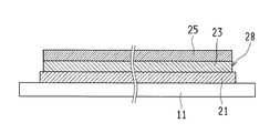
- FIG. 1 is an enlarged cross-sectional view showing an essential part of a solar cell module 1 according to Embodiment 1 of the present invention.
- the first translucent substrate 11, the solar cell unit 20, the resin sealing unit 30, and the second translucent substrate 12 are arranged in this order from the sunlight irradiation side. Arranged (laminated).
- the solar cell module 1 includes a mark portion 40 (specifically, a mark portion) formed between the boundary 30b between the solar cell portion 20 and the resin sealing portion 30 and the outer surface 12s of the second translucent substrate 12. Formed in a partial region within the range of the formation region 40r. Since a specific example of the mark unit 40 will be described in the second to fourth embodiments and the like, FIG. 1 shows an example corresponding to the second embodiment with an imaginary line (two-dot chain line).
- the solar cell module 1 has a recognition rate between the boundary 30b between the solar cell unit 20 and the resin sealing unit 30 and the outer surface 12s of the second light transmissive substrate 12 in the thickness direction. Since the high mark portion 40 is formed (arranged), it can be formed (arranged) in the plane direction without being restricted to the power generation region, and therefore the influence on the power generation region (power generation amount) and the influence on the mark portion 40 from the outside. In this state, the mechanical strength of the mark portion 40 is improved in a state in which a reduction in the amount of power generation is prevented, and durability, weather resistance, and reliability are improved.
- the mark portion 40 is placed at a position that does not affect power generation inside the solar cell module 1 (between the outer surface 12s of the second light-transmissive substrate 12 and the boundary 30b). Since it is in the enclosed form, it is possible to eliminate the influence from the outside without reducing the power generation amount, and to improve the durability, weather resistance, and reliability.
- substrate 12 are comprised, for example with the glass plate, and the solar cell part 20 was directly laminated
- the mark part 40 preferably displays information as a nameplate. That is, since the solar cell module 1 according to the present embodiment includes the mark portion 40 indicating information (for example, a manufacturer) as a nameplate in a form that protects it from the outside, the nameplate information can be obtained without attaching the nameplate. Since it can be displayed, the reliability of the product and the ease of handling are improved.
- the mark portion 40 formed as a nameplate nameplate information display example
- the mark part 40 is shown as a mark part 41 (see FIG. 2A) in the second embodiment, as a mark part 43 (see FIG. 3A) in the third embodiment, and as a mark part 44 (see FIG. 4A) in the fourth embodiment.
- the mark portion 41, the mark portion 43, and the mark portion 44 may be simply referred to as the mark portion 40 when it is not necessary to particularly distinguish them.
- the solar cell part 20 is comprised with the thin film solar cell.
- a transparent electrode layer 21, a photoelectric conversion layer 23, and a back electrode layer 25 are laminated in this order from the first light-transmissive substrate 11 side. Therefore, since the solar cell module 1 which concerns on this Embodiment comprises the solar cell part 20 by a thin film solar cell, it can suppress the material required for the solar cell part 20, and can improve productivity.
- FIG. 1 schematically shows another solar cell element portion 20c arranged (in series connection) adjacent to one solar cell element portion 20c.
- the solar cell element portion 20 c is separated from the other adjacent solar cell element portions 20 c by the first separation groove 22 and the second separation groove 26. Further, it is connected in series with another solar cell element portion 20 c arranged adjacent to the contact line 24.
- the first separation groove 22 is formed in the transparent electrode layer 21 and defines a basic region (region division) of the solar cell element portion 20c.
- the contact line 24 is formed so that the back electrode layer 25 is connected to the transparent electrode layer 21 on either side of the first separation groove 22 disposed on both sides of the transparent electrode layer 21, and is transparent to the back electrode layer 25. This is a connection path to the electrode layer 21.
- the second separation groove 26 is disposed adjacent to the contact line 24 and is formed so as to separate the photoelectric conversion layer 23 and the back electrode layer 25 from the photoelectric conversion layer 23 and the back electrode layer 25 of the adjacent solar cell element part 20c. Is done.
- the solar cell element portion 20c is formed in a strip shape, and is connected in series via the contact line 24 between the mutually adjacent ones.
- the solar cell module 1 that generates a high voltage is configured by the series connection of the solar cell element portions 20c.
- the specific example which comprises the solar cell module part 1 by connecting the solar cell element part 20c in series is further demonstrated in Embodiment 5.
- FIG. 5 The specific example which comprises the solar cell module part 1 by connecting the solar cell element part 20c in series is further demonstrated in Embodiment 5.
- the method for manufacturing the solar cell module 1 according to the present embodiment irradiates a light beam (not shown) through the second translucent substrate 12 to start from the boundary 30b between the solar cell unit 20 and the resin sealing unit 30.
- the manufacturing method of the solar cell module 1 according to the present embodiment has a recognition rate between the boundary 30b between the solar cell unit 20 and the resin sealing unit 30 and the outer surface 12s of the second light transmissive substrate 12. Since the high mark portion 40 can be formed (arranged) easily and with high accuracy, the solar cell module 1 having high durability, weather resistance, and reliability can be manufactured with high productivity.
- the step of forming the mark portion 40 is performed by laminating (adhering) the second light transmissive substrate 12 to the first light transmissive substrate 11, the solar cell portion 20, and the resin sealing portion 30. This is performed by irradiating a light beam (for example, a laser beam) from the outside after forming the solar cell module 1 with resin sealed inside.
- a light beam for example, a laser beam
- the member Since the light beam heats (absorbs heat) the member disposed at the focal position, the member can be denatured (discolored, decolored, clouded, etc.) to form a highly visible mark portion.
- the focal position of the light beam can be defined parallel to the first translucent substrate 11 and the like at an appropriate position of the resin sealing portion 30 in the thickness direction of the solar cell module 1.
- the planar mark part 40 can be formed corresponding to the (resin sealing part 30).
- the solar cell module 1 according to the present embodiment and the method for manufacturing the solar cell module 1 include other embodiments as a concept, and specific examples according to the present embodiment will be described in the other embodiments, respectively. Is done. The details of the method for manufacturing the solar cell module 1 will be further described in the fifth embodiment and thereafter.
- Embodiment 2 With reference to FIG. 2A and FIG. 2B, the solar cell module which concerns on this Embodiment, and the manufacturing method of a solar cell module are demonstrated. Since the basic configuration is the same as that of the first embodiment, the reference numerals are appropriately used and different items will be mainly described. In addition, about the manufacturing method of the solar cell module 1 which concerns on this Embodiment, Embodiment 6 demonstrates further detail.
- FIG. 2A is an enlarged cross-sectional view showing an essential part of solar cell module 1 according to Embodiment 2 of the present invention.
- FIG. 2B is an enlarged plan view showing the display state of the nameplate formed on the mark portion 41 (mark portion 40) of the solar cell module 1 viewed in the direction of arrow B in FIG. 2A.
- the mark portion 41 (mark portion 40) is formed in the resin sealing portion 30. Therefore, the solar cell module 1 can easily recognize the information displayed on the mark part 41 as compared with the case where the mark part 40 is arranged on the second light-transmissive substrate 12 (see the fourth embodiment).
- the rate (visibility) can be improved and durability, weather resistance, and reliability can be maintained.
- Resin sealing portion 30 is formed by the following method. That is, after the solar cell portion 20 is formed in a laminated state on the first translucent substrate 11, a black ionomer resin containing carbon black (black carbon) (the metal ions between the molecules of the ethylene methacrylic acid copolymer) A cross-linked ionomer resin) is stacked on the solar cell portion 20 as a sealing resin (adhesive) molded into a sheet shape, and the second light-transmitting substrate 12 is further stacked on the ionomer resin (adhesive).
- the first light-transmitting substrate 11, the solar cell portion 20, an ionomer resin as an adhesive (sealing resin) before forming the resin sealing portion 30, and the second light-transmitting substrate 12 are stacked in this order in a vacuum. For example, heat and pressure are applied at 170 ° C. by a laminating apparatus (vacuum laminating step).
- a resin sealing portion 30 that seals the solar cell portion 20 between the first light-transmitting substrate 11 and the second light-transmitting substrate 12 is formed by a vacuum laminating process. That is, the solar cell module 1 is in a completed state.
- the mark portion 41 is formed as a name plate by performing laser processing (marking processing with laser light) on the resin sealing portion 30 from the second translucent substrate 12 side.
- the mark portion 41 since the resin sealing portion 30 is black, the mark portion 41 (name plate) changes the black color to the black ground color, for example, information in the form of gray (characters, figures, etc.) ). Since the resin sealing portion 30 is black, it effectively generates heat by irradiation with laser light, and can easily discolor carbon black, thereby improving the recognition rate.
- FIG. 2B white and black are reversed in view of the visibility of the drawing. That is, the background is shown in white (ground color), and the nameplate information (character 46, symbol 47, specification character 48, two-dimensional code 49) as the mark part 41 (mark part 40) is shown in black.
- the information character 46, symbol 47, specification character 48, two-dimensional code 49
- the two-dimensional code includes a bar code and other plane codes. In particular, a barcode is preferable because of its high versatility and ease of laser processing.
- the characters 46 can display the manufacturer, product name, product number, etc.
- the symbols 47 can display warnings, special graphic characters, etc.
- the specification characters 48 can display specifications (information on electrical characteristics, etc.). It is not limited to.
- FIG. 2B only shows examples of display contents (information) of the nameplate, and the display contents are not limited to these.
- the resin sealing portion 30 uses black ionomer resin as the sealing resin. Therefore, since the solar cell module 1 forms the resin sealing portion 30 with a black ionomer resin, the solar cell module 1 improves the endothermic property with respect to the laser light in the resin sealing portion 30, so that the discoloration of the ionomer resin by the laser light is effective. Therefore, the mark unit 40 can display the information with high accuracy.
- the sealing resin (ionomer resin) applied for forming the resin sealing portion 30 preferably contains carbon black. That is, in the present embodiment, since the resin sealing portion 30 (sealing resin) contains carbon black, the mark portion that effectively displays the discoloration of the carbon black by the laser light and displays the information more clearly. 40, and the recognition rate is improved in both visual recognition and automatic recognition using a camera or the like.
- the mark portion 41 (mark portion 40) is formed as a nameplate, information as a nameplate is displayed. Therefore, since the mark part 41 (mark part 40) includes the mark part 41 that displays information (for example, a manufacturer) as a nameplate in a form that protects it from the outside, the nameplate information is displayed without attaching the nameplate. This improves product reliability and ease of handling.
- the mark part 41 (mark part 40) displays information on electrical characteristics. Therefore, since the solar cell module 1 can display information on electrical characteristics (electrical specifications) without attaching a nameplate, the reliability of the product and the ease of handling are improved.
- the mark part 41 (mark part 40) includes a display by a two-dimensional code. Therefore, since the solar cell module 1 can automatically read a code reader that reads a two-dimensional code, it is possible to efficiently deal with handling and maintenance.
- the resin sealing portion 30 contains carbon black, and the light beam (laser beam) discolors the carbon black to mark the mark portion. 41 displays information. Therefore, the manufacturing method of the solar cell module 1 forms the mark portion 41 by irradiating the light beam to change the color of the carbon black, so that the mark portion 41 having a high recognition rate can be formed.
- Embodiment 3 With reference to FIG. 3A and FIG. 3B, the solar cell module which concerns on this Embodiment, and the manufacturing method of a solar cell module are demonstrated. Since the basic configuration is the same as that of the first embodiment and the second embodiment, reference numerals are appropriately used and different items will be mainly described. In addition, about the manufacturing method of the solar cell module 1 which concerns on this Embodiment, Embodiment 7 demonstrates further detail.
- FIG. 3A is an enlarged cross-sectional view showing an essential part of the solar cell module 1 according to Embodiment 3 of the present invention.
- FIG. 3B is an enlarged plan view showing a display state of the nameplate formed on the mark portion 43 (mark portion 40) of the solar cell module 1 viewed in the direction of arrow B in FIG. 3A.
- the mark portion 43 (mark portion 40) is formed in the embedded member 42 embedded in the resin sealing portion 30. Therefore, the solar cell module 1 forms the mark portion 43 by the embedded member 42 embedded in the resin sealing portion 30 even when the temperature resistance of the sealing resin forming the resin sealing portion 30 is not sufficient. Productivity and reliability can be improved.
- the mark part 43 in the present embodiment is formed from the second translucent substrate 12 side.
- a name plate is formed by performing laser processing on the embedded member 42. That is, laser processing is performed by adjusting the focus of the laser light to the position of the embedded member 42.
- black colored PET polyethylene terephthalate
- copper foil or the like
- the heat generated by the laser processing is effectively generated by making the PET black, it is possible to easily and efficiently form the mark portion 40 with a high recognition rate.
- the embedded member 42 is embedded in the resin sealing portion 30 with respect to the state in which the first light transmitting substrate 11 and the solar cell portion 20 are formed, the element side insulating sheet 32, the embedded member 42, the covering insulating sheet 33,
- the two light-transmitting substrates 12 are sequentially laminated and heated and pressurized by a vacuum laminating apparatus (vacuum laminating step).
- the element side insulating sheet 32 and the covering insulating sheet 33 are integrated as the resin sealing portion 30 by heat and pressure in the vacuum laminating process.
- the two-layer configuration of the element side insulating sheet 32 and the covering insulating sheet 33 will be described in more detail in the seventh embodiment.
- the element-side insulating sheet 32 and the covering insulating sheet 33 are formed into a sheet shape with, for example, ionomer resin and are transparent.
- the covering insulating sheet 33 is thin (for example, it has been experimentally confirmed that 300 ⁇ m or less is preferable) in order to prevent discoloration due to laser processing.
- the thickness of the embedded member 42 is preferably set to, for example, 300 ⁇ m or less so that bubbles are not generated in the resin sealing portion 30 around the embedded member 42 in the vacuum laminating process using a vacuum laminating apparatus.
- the buried member 42 has a thickness of 50 ⁇ m, for example.
- the covering insulating sheet 33 is shown as being disposed corresponding to the entire surface of the solar cell module 1 (FIG. 3A), but covers the embedded member 42 so as to be slightly larger than the planar shape of the embedded member 42 (implementation). It is preferable to reduce the material.
- the display information (FIG. 3B) of the mark part 43 (mark part 40) is the same as in the second embodiment. Specifically, since the embedded member 42 is black, the display state is the same as that of the second embodiment within the range of the embedded member 42.
- Embodiment 4 With reference to FIG. 4A and FIG. 4B, the solar cell module which concerns on this Embodiment, and the manufacturing method of a solar cell module are demonstrated. Since the basic configuration is the same as that of the first to third embodiments, the reference numerals are appropriately used and different items are mainly described. In addition, about the manufacturing method of the solar cell module 1 which concerns on this Embodiment, Embodiment 8 demonstrates further detail.
- FIG. 4A is an enlarged cross-sectional view showing an essential part of the solar cell module 1 according to Embodiment 4 of the present invention.
- FIG. 4B is an enlarged plan view showing the display state of the nameplate formed on the mark portion 44 (mark portion 40) of the solar cell module 1 viewed in the direction of arrow B in FIG. 4A.
- the mark portion 44 (mark portion 40) is formed on the second light-transmissive substrate 12. Therefore, since the solar cell module 1 forms the mark part 44 (mark part 40) in the 2nd translucent board
- the resin sealing portion 30 is irrelevant to laser processing, it is formed of a transparent or black ionomer resin. However, as described above, in order to improve the visibility of the mark portion 44, black or other colors are used. It is preferable to have it. By setting the background to black, when the mark portion 44 is formed on the second translucent substrate 12, the mark portion 44 having a high recognition rate can be obtained.
- the mark part 44 is arranged on the outer surface 12s side from the center of the thickness of the second light-transmitting substrate 12. Therefore, since the solar cell module 1 arrange
- the information (display contents) indicated by the mark portion 44 (mark portion 40) as a nameplate in FIG. 4B is simplified with respect to the information of the mark portion 41 shown in FIG. 2B and the information of the mark portion 43 shown in FIG. 3B. Yes. Since the laser processing on the second light-transmissive substrate 12 made of a glass plate requires a long time, the display content of the mark portion 44 (name plate) is simplified. When the mark part 44 is simplified, the mark part 40 (mark part 41, mark part 43) shown in other embodiments can be used in combination. FIG. 4B only shows an example when the display content (information) of the nameplate is simplified, and the display content is not limited to these.
- the solar cell module 1 it is preferable to perform laser processing with a focal position outside the center of the thickness of the second light-transmissive substrate 12.
- the focal position is closer to the resin sealing portion 30 than the center of the thickness of the second translucent substrate 12, the influence on the resin sealing portion 30 and further, the solar cell portion 20 (back surface electrode, photoelectric conversion). This is because there is a risk that the solar cell unit 20 may be damaged.
- the position of the mark portion 44 in the thickness direction of the second light transmissive substrate 12 may be focused at a position having a depth of about 0.5 mm or more from the outer surface 12s of the second light transmissive substrate 12. preferable. This is to suppress the probability that the mark portion 44 is erased even when the outer surface 12 s of the second light-transmissive substrate 12 is scraped by an external mechanical influence. Therefore, when the thickness of the second translucent substrate 12 is about 4 mm, for example, the position of the mark portion 44 is preferably about 0.5 mm to 2 mm from the outer surface 12s.
- substrate 11 the solar cell part 20, the insulating sheet 31 (refer FIG. 5B. Resin sealing part 30), and the 2nd translucent board
- a part of the mark portion 40 is not affected by the result of characteristic inspection. It is also possible to form a symbol such as a manufacturer's logotype or CE mark.
- the solar cell module 1 according to the present embodiment is the same as the solar cell module 1 shown in the first to fourth embodiments.
- the manufacturing method of the solar cell module 1 which concerns on this Embodiment is the resin sealing part 30 with respect to the solar cell part 20 (solar cell element part 20c) simplified and shown in Embodiment 1 thru
- the present invention relates to a method for laminating the second light-transmissive substrate 12, a method for attaching the terminal box 50, and a method for forming the mark portion 40 (mark portion 41, mark portion 43, mark portion 44).
- the solar cell part 20 which concerns on this Embodiment is comprised with the thin film solar cell as shown in Embodiment 1.
- FIG. 5A is an enlarged cross-sectional view showing an enlarged state of a main part in which solar cell unit 20 (thin film solar cell) is formed on first light-transmissive substrate 11 in solar cell module 1 according to Embodiment 5 of the present invention. It is.
- a transparent electrode layer 21, a photoelectric conversion layer 23, and a back electrode layer 25 are laminated in this order from the first light-transmissive substrate 11 side.
- the first separation groove 22 separates the transparent electrode layer 21 for each solar cell element part 20c
- the second separation groove 26 separates the photoelectric conversion layer 23 and the back electrode layer 25 for each solar cell element part 20c.
- the photoelectric conversion layer 23 is formed with a contact line 24 that connects the solar cell element portions 20c to each other, and the contact line 24 is formed on one transparent electrode layer 21 between the adjacent solar cell element portions 20c.
- the other back electrode layer 25 is connected.
- the solar cell element portion 20c is formed in a strip shape (see FIG. 5B) by the second separation groove 26, and the solar cell element portions 20c adjacent to each other are connected in series to constitute the solar cell module 1. That is, the solar cell module 1 which connects the solar cell element parts 20c in series and generates an output voltage corresponding to the number of series is configured.
- FIG. 5B is an exploded view showing the insulating sheet 31 forming the resin sealing portion 30 in the solar cell module 1 according to Embodiment 5 of the present invention and the second translucent substrate 12 laminated on the insulating sheet 31. It is a perspective view.
- a collector electrode 15p (positive collector electrode) is disposed on one of the solar cell element portions 20c disposed at both ends of the first light-transmissive substrate 11, and a collector electrode 15m (minus) is disposed on the other solar cell element portion 20c.
- Current collecting electrode The extraction lead 17 is connected to each of the collecting electrode 15p and the collecting electrode 15m.
- An insulating sheet 16 that insulates the extraction lead 17 from the solar cell element portion 20 c is disposed between the solar cell element portion 20 c and the extraction lead 17. The leading end of the extraction lead 17 is bent in a direction perpendicular to the solar cell unit 20 in order to lead the extraction lead 17 to the outside.
- the insulating sheet 31 that acts as a sealing resin for forming the resin sealing portion 30 is provided with an opening 31 h that leads the tip of the take-out lead 17 to the outside.
- a lead connection hole 12 h that leads the lead 17 to the outside is also formed in the second translucent substrate 12. Therefore, the leading end of the take-out lead 17 is led out to the outside through the opening 31h and the lead connection hole 12h (see FIG. 5C).
- the specific form of the insulating sheet 31 is different in each of the second to fourth embodiments.
- the insulating sheet 31 is, for example, a sealing resin (adhesive) obtained by molding a black ionomer resin into a sheet shape.
- the insulating sheet 31 is composed of two layers of the element side insulating sheet 32 and the covering insulating sheet 33, and is laminated with the black embedded member 42 interposed therebetween. That is, since the embedded member 42 is formed in black and the mark portion 41 is formed in the embedded member 42 by laser processing, the insulating sheet 31 (element-side insulating sheet 32, covering insulating sheet 33) is made of, for example, a transparent ionomer resin. Is done. Details of the element side insulating sheet 32 and the covering insulating sheet 33 will be further described in the seventh embodiment.
- the insulating sheet 31 is irrelevant to the laser processing, and may be either transparent or black as long as it is an ionomer resin, for example.
- FIG. 5C is a perspective view showing a state in which the resin-sealed portion 30 is formed by laminating the first light-transmissive substrate 11 and the second light-transmissive substrate 12 in the solar cell module 1 according to Embodiment 5 of the present invention. It is.
- the first light-transmitting substrate 11 and the second light-transmitting substrate 12 are laminated (adhered) with the solar cell portion 20 and the resin sealing portion 30 interposed therebetween.
- the leading end of the lead 17 is led out from the lead connection hole 12h.
- FIG. 5D is a plan view showing an external appearance of the second translucent substrate 12 side after the terminal box 50 and the mark portion 40 are formed in the solar cell module 1 according to Embodiment 5 of the present invention.
- the module lead 51 is connected to the tip of the take-out lead 17, and the connection portion between the take-out lead 17 and the module lead 51 is connected to the second portion.
- the terminal box 50 mounted on the translucent substrate 12 is covered and protected.
- the module lead 51 is taken out from the terminal box 50 and applied to connection with other solar cell modules 1.
- the mark portion 40 is formed on the solar cell module 1.
- the specific configuration of the mark unit 40 is as shown in the second to fourth embodiments.
- or FIG. 17C the manufacturing method of the solar cell module which concerns on this Embodiment, and a solar cell module is demonstrated.
- the solar cell module and the solar cell module manufacturing method according to the present embodiment relate to a more specific structure and manufacturing method of the solar cell module 1 shown in the first to fifth embodiments (particularly the embodiment). 2, which corresponds to a detailed embodiment of FIG. 2A and FIG. 2B.) Therefore, reference numerals are appropriately used and different items will be mainly described.
- the solar cell part 20 of the solar cell module 1 according to the present embodiment is formed as a thin film solar cell and can be applied to other embodiments as it is. Moreover, below, it is set as the solar cell module 1 including the state before completion.
- FIG. 6A is a schematic plan view showing a schematic state of the solar cell module 1 according to Embodiment 6 of the present invention on the first translucent substrate 11 side.
- FIG. 6B is a schematic plan view showing a schematic state of the solar cell module 1 according to Embodiment 6 of the present invention on the second light transmissive substrate 12 side.
- the solar cell unit 20 of the solar cell module 1 is a thin film solar cell. Therefore, on the first light transmissive substrate 11 side, a state in which the strip-shaped solar cell element portions 20c are arranged in series via the first light transmissive substrate 11 is shown. In addition, the 1st separation groove 22 is arrange
- the resin sealing portion 30 is made of, for example, a black ionomer resin on the second translucent substrate 12 side, a black state is shown and the mark portion 40 can be visually recognized from the outside. Has been. Note that the mark portion 40 is formed in various states (see the mark portion 41, the mark portion 43, and the mark portion 44 in the first to fourth embodiments). .
- the first translucent substrate 11 and the second translucent substrate 12 are made of a glass plate having a width of 1000 mm ⁇ a length of 1400 mm ⁇ a thickness of about 4 mm. Insulation separation that isolates and isolates the solar cell element portion 20c from the periphery around the solar cell portion 20 (solar cell element portion 20c) (peripheral end portions of the first light-transmissive substrate 11 and the second light-transmissive substrate 12). Region 28 is formed.
- FIG. 7A is a cross-sectional view showing a cross section when the transparent electrode layer 21 is laminated on the first translucent substrate 11 in the manufacturing process of the solar cell module 1 as viewed in the direction of arrows AA in FIG. 6A. Note that some hatchings in the cross section may be omitted in consideration of the visibility of the drawings (the same applies to the following embodiments).
- FIG. 7B is a cross-sectional view showing a cross section when the transparent electrode layer 21 is laminated on the first translucent substrate 11 in the manufacturing process of the solar cell module 1 seen in the direction of arrow BB in FIG. 6A.
- the transparent electrode layer 21 is formed by laminating SnO 2 by thermal CVD (vapor phase growth method) on the surface of the first translucent substrate 11 on the side where the solar cell unit 20 is formed.
- FIG. 8A is a cross-sectional view showing a cross section when the transparent electrode layer 21 is separated by the first separation groove 22 in the manufacturing process of the solar cell module 1 seen in the direction of arrow AA in FIG. 6A.
- FIG. 8B is a cross-sectional view showing a cross section when the transparent electrode layer 21 is separated by the first separation groove 22 in the manufacturing process of the solar cell module 1 as seen in the direction of arrow BB in FIG. 6A.
- first light-transmissive substrate 11 First formed in the longitudinal direction of the solar cell element portion 20c (hereinafter referred to as “longitudinal direction of the first light-transmissive substrate 11”) by irradiation with a fundamental wave (wavelength 1064 nm) of a YAG (Yttrium Aluminum Garnet) laser beam.
- the transparent electrode layer 21 is separated by the separation groove 22. That is, a region corresponding to the solar cell element portion 20 c is defined by the first separation groove 22 formed in the transparent electrode layer 21.
- the fundamental wave of the YAG laser beam is irradiated.
- the part of the transparent electrode layer 21 is removed, and a strip-shaped first separation groove 22 for separating the transparent electrode layer 21 into a strip shape is formed.
- a fundamental wave of YVO 4 (Yttrium Orthovanadate) laser light (wavelength 1064 nm) or a fundamental wave of fiber laser light (wavelength 1064 nm) may be used.
- the first translucent substrate 11 on which the first separation grooves 22 were formed was ultrasonically cleaned with pure water.
- FIG. 9A is a cross-sectional view showing a cross section when the photoelectric conversion layer 23 is formed in the manufacturing process of the solar cell module 1 as viewed in the direction of arrows AA in FIG. 6A.
- FIG. 9B is a cross-sectional view showing a cross section when the photoelectric conversion layer 23 is formed in the manufacturing process of the solar cell module 1 as seen in the direction of arrow BB in FIG. 6A.
- a photoelectric conversion layer 23 was formed so as to cover the transparent electrode layer 21 in which the first separation groove 22 was formed.
- the photoelectric conversion layer 23 includes a p layer made of a p-type hydrogenated amorphous silicon film, an i layer made of an i-type hydrogenated amorphous silicon film, and an n layer made of an n-type hydrogenated amorphous silicon film in this order.
- a top cell an amorphous silicon film power generation element having a pin structure
- a bottom cell (a microcrystalline silicon film power generation element having a pin structure) is formed by stacking an i layer made of n and an n layer made of an n-type microcrystalline silicon film in this order.
- a semiconductor photoelectric conversion layer can be used as the photoelectric conversion layer 23.
- a p-layer, an i-layer, and an n-layer made of an amorphous silicon thin film are stacked in this order from the first translucent substrate 11 side.
- a cell (first photoelectric conversion layer) and a bottom cell (second photoelectric conversion layer) in which a p layer, an i layer, and an n layer made of a microcrystalline silicon thin film are stacked in this order on the top cell are stacked. can do.
- the amorphous silicon thin film (first photoelectric conversion layer) and the microcrystalline silicon thin film (second photoelectric conversion layer) can be formed by, for example, a plasma CVD method.
- a top cell in which a p layer, an i layer, and an n layer made of an amorphous silicon thin film are stacked in this order from the first light transmitting substrate 11 side.
- a middle cell in which a p layer, an i layer, and an n layer made of an amorphous silicon thin film are laminated in this order on the top cell, and a p layer made of a microcrystalline silicon thin film on the middle cell , I layer, and n layer can be stacked to form a bottom cell (third photoelectric conversion layer).
- the amorphous silicon thin film (first photoelectric conversion layer, second photoelectric conversion layer) and microcrystalline silicon thin film (third photoelectric conversion layer) can be formed by, for example, a plasma CVD method.
- a photoelectric conversion layer exceeding three layers can be formed.
- Each photoelectric conversion layer from the first photoelectric conversion layer to the third photoelectric conversion layer is formed of a silicon-based semiconductor of the same type (for example, an i layer for an amorphous silicon thin film as a p layer and an amorphous silicon thin film as an n layer).
- they may be formed of different types of silicon-based semiconductors (for example, an i layer for an amorphous silicon thin film as a p layer and a microcrystalline silicon thin film as an n layer).
- the p-type semiconductor layer and the i-type semiconductor layer may be formed using amorphous silicon
- the n-type semiconductor layer may be formed using microcrystalline silicon.
- the p-type semiconductor layer and the n-type semiconductor layer may be formed of silicon carbide or silicon germanium, and the i-type semiconductor layer may be formed of silicon.
- the p-type, i-type, and n-type semiconductor layers may have a single-layer structure or a multi-layer structure. Each layer in the case of a multi-layer structure may be formed of different types of silicon-based semiconductors.
- amorphous silicon thin film includes a thin film made of a hydrogenated amorphous silicon-based semiconductor (a-Si: H) in which dangling bonds of silicon are terminated with hydrogen.
- a-Si: H hydrogenated amorphous silicon-based semiconductor
- microcrystalline silicon thin film includes a thin film made of a hydrogenated microcrystalline silicon-based semiconductor ( ⁇ c-Si: H) in which dangling bonds of silicon are terminated with hydrogen.
- the thickness of the photoelectric conversion layer 23 is not particularly limited, and can be, for example, 200 nm or more and 5 ⁇ m or less. Moreover, the formation method of the photoelectric converting layer 23 is not limited to the plasma CVD method.
- FIG. 10A is a cross-sectional view showing a cross section when the contact line 24 is formed in the manufacturing process of the solar cell module 1 as viewed in the direction of arrow AA in FIG. 6A.
- FIG. 10B is a cross-sectional view showing a cross section when the contact line 24 is formed in the manufacturing process of the solar cell module 1 as seen in the direction of arrow BB in FIG. 6A.
- the photoelectric conversion layer 23 By irradiating the photoelectric conversion layer 23 from the first translucent substrate 11 side while moving the second harmonic (wavelength 532 nm) of the YAG laser light in the longitudinal direction of the first translucent substrate 11, the photoelectric conversion layer A strip-shaped contact line 24 for separating 23 into strips was formed.
- a second harmonic (wavelength: 532 nm) of YVO 4 laser light may be used as the light beam for forming the contact line 24.
- FIG. 11A is a cross-sectional view showing a cross section when the back electrode layer 25 is formed in the manufacturing process of the solar cell module 1 as viewed in the direction of arrows AA in FIG. 6A.
- FIG. 11B is a cross-sectional view showing a cross section when the back electrode layer 25 is formed in the manufacturing process of the solar cell module 1 as seen in the direction of arrow BB in FIG. 6A.
- a back electrode layer 25 was formed so as to cover the photoelectric conversion layer 23 on which the contact line 24 was formed.
- the back electrode layer 25 was formed by forming a 50 nm thick ZnO (zinc oxide) film by magnetron sputtering and then laminating a 125 nm thick Ag (silver) film.
- FIG. 12A is a cross-sectional view showing a cross section when the second separation groove 26 is formed in the manufacturing process of the solar cell module 1 seen in the direction of arrow AA in FIG. 6A.
- FIG. 12B is a cross-sectional view showing a cross section when the second separation groove 26 is formed in the manufacturing process of the solar cell module 1 as seen in the direction of arrow BB in FIG. 6A.
- a strip-shaped second separation groove 26 for separating the layer 23 and the back electrode layer 25 into a strip shape was formed.
- the second harmonic of the YVO 4 laser beam may be used as the light beam that forms the second separation groove 26.
- a plurality of solar cell element portions 20c are formed in a direction orthogonal to the longitudinal direction of the first translucent substrate 11 (left and right direction in the drawing of FIG. 12A). 20c will be in the state connected in series with respect to the other adjacent solar cell element part 20c. That is, the solar cell unit 20 (solar cell string) was formed by the plurality of solar cell element units 20c electrically connected in series.
- FIG. 13A is a cross-sectional view showing a cross section when the peripheral groove 27 is formed in the manufacturing process of the solar cell module 1 as seen in the direction of arrow AA in FIG. 6A.
- FIG. 13B is a cross-sectional view showing a cross section when the peripheral groove 27 is formed in the manufacturing process of the solar cell module 1 seen in the direction of arrow BB in FIG. 6A.
- the peripheral groove 27 was formed in the direction orthogonal to the longitudinal direction of the first translucent substrate 11 by irradiating the second harmonic of the YAG laser beam.
- the peripheral groove 27 is formed by removing the back electrode layer 25 and the photoelectric conversion layer 23.
- 14A is a cross-sectional view showing a cross section when the insulating isolation region 28 is formed in the manufacturing process of the solar cell module 1 as seen in the direction of arrow AA in FIG. 6A.
- FIG. 14B is a cross-sectional view showing a cross section when the insulating isolation region 28 is formed in the manufacturing process of the solar cell module 1 as seen in the direction of arrow BB in FIG. 6A.
- Irradiation is performed while moving the fundamental wave of the YAG laser beam so as to surround the periphery of the solar cell string (the solar cell unit 20 formed by connecting the solar cell element units 20c in series) (laser beam irradiation width: 650 ⁇ m).
- the transparent electrode layer 21, the photoelectric conversion layer 23, and the back electrode layer 25 were removed to form the insulating isolation region 28.
- the insulating isolation region 28 is formed by removing the transparent electrode layer 21, the photoelectric conversion layer 23, and the back electrode layer 25 from the end of the first translucent substrate 11 by about 12 mm in width.
- a fundamental wave of YVO 4 laser light may be used as a light beam for forming the insulating isolation region 28.
- FIG. 15A is a cross-sectional view showing a cross section when the collecting electrode 15p and the collecting electrode 15m are formed in the manufacturing process of the solar cell module 1 as seen in the direction of arrow AA in FIG. 6A.
- FIG. 15B is a cross-sectional view showing a cross section when the collecting electrode 15p and the collecting electrode 15m are formed in the manufacturing process of the solar cell module 1 seen in the direction of arrow BB in FIG. 6A.
- a collector electrode 15p was formed on one side of the solar cell element portion 20c located at both ends of the solar cell string (solar cell portion 20), and a collector electrode 15m was formed on the other side.
- the collecting electrode 15p and the collecting electrode 15m are connected to the back electrode layer 25 of the solar cell element portion 20c through a metal paste 14 made of silver paste. Further, the current collecting electrode 15p and the current collecting electrode 15m are arranged extending in the longitudinal direction of the solar cell element portion 20c (see FIG. 5B).
- 16A is a cross-sectional view showing a cross section when the resin sealing portion 30 and the second light-transmitting substrate 12 are laminated and bonded in the manufacturing process of the solar cell module 1 as seen in the direction of arrows AA in FIG. 6A. It is.
- 16B is a cross-sectional view showing a cross section when the resin sealing portion 30 and the second light-transmitting substrate 12 are laminated and bonded in the manufacturing process of the solar cell module 1 seen in the direction of arrow BB in FIG. 6A. It is.
- substrate 12 are piled up, the solar cell part 20 is resin-sealed, and the solar cell module 1 is attached. Form.
- An insulating sheet 31 (see FIG. 5B) as a sealing resin molded into a sheet shape by adding black carbon to an ionomer resin in which the molecules of the ethylene methacrylic acid copolymer are cross-linked with metal ions is formed into a sheet shape.
- a tempered back glass (second translucent substrate 12) having a thickness of 3.2 mm is overlaid on the insulating sheet 31, and then the solar cell unit 20 is placed by a vacuum laminating apparatus (vacuum laminating step).
- the resin sealing portion 30 and the second translucent substrate 12 were laminated and bonded.
- FIG. 17A is a cross-sectional view showing a cross section when the mark portion 41 (mark portion 40) is formed in the manufacturing process of the solar cell module 1 seen in the direction of arrow AA in FIG. 6A.
- FIG. 17B is a cross-sectional view showing a cross section when the mark portion 41 (mark portion 40) is formed in the manufacturing process of the solar cell module 1 seen in the direction of arrow BB in FIG. 6A.
- FIG. 17C is a plan view showing a state of bubbles generated when the formation condition of the mark portion 41 (mark portion 40) is changed in FIG. 17A.
- the terminal box 50 (see FIG. 5D) is mounted on the second light-transmissive substrate 12 of the solar cell module 1, the terminal box is filled with silicone resin (not shown), and a final output inspection is performed. In addition, you may implement an output test
- the laser sealing process is performed on the resin sealing portion 30 from the second translucent substrate 12 side to form the mark portion 41.
- the position of the mark portion 41 in the thickness direction is preferably such that the laser beam is focused on the side close to the second light transmissive substrate 12. This is because the solar cell unit 20 is not affected by the heat of the laser beam.
- the mark portion 41 is formed as a nameplate.
- the display mode of the nameplate is, for example, as shown in FIG. 2B of the second embodiment.
- a second harmonic (wavelength: 532 nm) of a YVO 4 laser was used as a laser beam to be used.
- a second harmonic (wavelength 532 nm) of a YAG laser may be used. That is, a SHG (Second Harmonic Generation) laser can be applied.
- the SHG laser is a second harmonic that generates a second harmonic wavelength (second harmonic (wavelength 532 nm) with respect to 1064 nm) with respect to a fundamental wavelength (for example, the fundamental wavelength 1064 nm of a YVO 4 laser). It is a generation laser.
- the present inventor When the present inventor performs processing with a laser beam in the same infrared region as the fundamental wave (wavelength 1064 nm) of each laser, the amount of gas generated in the resin sealing portion 30 increases due to the influence of heat from the laser beam. In addition, it has been newly found that gas accumulation tends to occur in the laser processed region.
- the gas reservoir is visually recognized as bubbles 41b (FIG. 17C) from the outside, and there is a risk of causing poor appearance and reduced visibility (recognition rate reduction).
- processing can also be performed with the third harmonic (wavelength 355 nm) of a YVO 4 laser.
- the processing conditions for forming the mark portion 41 were a processing point power of 1.5 W, a repetition frequency of 30 KHz, and a processing speed of 1000 mm / s.
- the energy density (J / mm 2 ) at the processing point is preferably between 0.015 (J / mm 2 ) and 0.07 (J / mm 2 ). If it is less than 0.015 (J / mm 2 ), the processing margin is reduced, the discoloration (color development) is poor, and the character recognition is poor. On the other hand, if it exceeds 0.07 (J / mm 2 ), bubbles are likely to be generated.
- the processing conditions at this time are conditions when a second harmonic (532 nm) laser beam is applied to the black ionomer resin.
- a galvano scanner system is advantageous in terms of tact.
- the light beam is preferably generated by an SHG laser. That is, in the method for manufacturing solar cell module 1 according to the present embodiment, the light beam is generated by the SHG laser, so it is possible to suppress the generation of heat and prevent the generation of bubbles, and improve the quality and the recognition rate. be able to.
- FIG. 18A and FIG. 18B With reference to FIG. 18A and FIG. 18B, the solar cell module which concerns on this Embodiment, and the manufacturing method of a solar cell module are demonstrated.
- the solar cell module and the manufacturing method of the solar cell module according to the present embodiment relate to a more specific structure and manufacturing method of the solar cell module 1 shown in the first to sixth embodiments (particularly the embodiment). 3, corresponding to the detailed embodiment for FIG. 3A and FIG. 3B).
- the solar cell unit 20 of the solar cell module 1 according to the present embodiment is formed as a thin film solar cell.
- the solar cell module 1 including a state before completion is used.
- FIG. 18A is a cross-sectional view showing a cross section when the mark portion 43 (mark portion 40) is formed in the manufacturing process of the solar cell module 1 as seen in the direction of arrow AA in FIG. 6A.
- FIG. 18B is a cross-sectional view showing a cross section when the mark portion 43 (mark portion 40) is formed in the manufacturing process of the solar cell module 1 seen in the direction of arrow BB in FIG. 6A.
- the mark portion 41 (mark portion 40) is not directly formed by laser processing on the resin sealing portion 30 (the second and sixth embodiments), but the resin sealing portion 30 (element side).
- the embedded member 42 was embedded in the insulating sheet 32 and the covering insulating sheet 33), and the embedded member 42 was subjected to laser processing to form the mark portion 43 (mark portion 40).
- the embedded member 42 is 100 mm square and 50 ⁇ m thick black PET (see Embodiment 3). By making the embedded member 42 black, the visibility of the mark portion 43 can be improved and a high recognition rate can be realized.
- the embedded member 42 is disposed on the element-side insulating sheet 32, the covering insulating sheet 33 is disposed so as to cover the embedded member 42, and the solar cell module 1 is vacuum-laminated with the second light-transmitting substrate 12 overlaid thereon.
- a heat and pressure treatment is performed by an apparatus (vacuum laminating step).
- the embedding member 42 is embedded in the resin sealing portion 30 (the element side insulating sheet 32 and the covering insulating sheet 33) by the vacuum laminating process.
- the element side insulating sheet 32 and the covering insulating sheet 33 are integrated in a vacuum laminating process to constitute the resin sealing portion 30.
- the covering insulating sheet 33 has a larger planar shape than the embedded member 42 in order to completely cover the embedded member 42, and specifically, is 125 mm square.
- the covering insulating sheet 33 was formed by molding an ionomer resin in which the molecules of the ethylene methacrylic acid copolymer were cross-linked with metal ions into a transparent sheet shape to a thickness of 100 ⁇ m.
- the second harmonic (532 nm) of the YVO 4 laser was used as the laser beam, and the processing conditions when forming the mark portion 43 were a processing point power of 0.4 W, a repetition frequency of 30 KHz, and a processing speed of 1000 mm / s.
- the burying member 42 is separated from the second light-transmitting substrate 12 because it does not have adhesiveness to the second light-transmitting substrate 12 (glass plate). Maintain state. Therefore, the appearance is not clear, and the gas (bubbles) generated when laser processing is performed further deteriorates the visibility. Therefore, it is preferable to use the covering insulating sheet 33 that covers the embedded member 42.
- the thickness of the embedded member 42 is preferably 300 ⁇ m or less. This is because if it exceeds 300 ⁇ m, bubbles are generated around the embedded member 42 in the vacuum laminating process. In addition, if the thickness of the covering insulating sheet 33 exceeds 300 ⁇ m, the transparent covering insulating sheet 33 may be slightly discolored by the laser beam, and therefore it is preferably 300 ⁇ m or less.
- the covering insulating sheet 33 it is preferable to select a material having less absorption with respect to the wavelength band of the laser light to be used.
- the covering insulating sheet 33 according to the present embodiment has a slightly larger size than the embedded member 42. Although it is possible to cover the entire first transparent substrate 11, the second transparent substrate 12, and the resin sealing portion 30 (insulating sheet 31) (1000 mm ⁇ 1400 mm), the material cost is considered. Then, it is more preferable to arrange partially.
- copper foil or the like is applicable in addition to PET. That is, any material that can be marked by laser processing may be used.
- the mark part 43 is formed as a nameplate.
- the display form of the nameplate is, for example, as shown in FIG. 3B of the third embodiment.
- FIG. 19A and FIG. 19B With reference to FIG. 19A and FIG. 19B, the solar cell module which concerns on this Embodiment, and the manufacturing method of a solar cell module are demonstrated.
- the solar cell module and the solar cell module manufacturing method according to the present embodiment relate to a more specific structure and manufacturing method of the solar cell module 1 shown in the first to seventh embodiments (particularly the embodiment). 4, corresponding to the detailed embodiment of FIG. 4A and FIG. 4B.) Therefore, the reference numerals are appropriately used and different items will be mainly described.
- the solar cell unit 20 of the solar cell module 1 according to the present embodiment is formed as a thin film solar cell.
- the solar cell module 1 including a state before completion is used.
- FIG. 19A is a cross-sectional view showing a cross section when the mark portion 44 (mark portion 40) is formed in the manufacturing process of the solar cell module 1 seen in the direction of arrow AA in FIG. 6A.
- FIG. 19B is a cross-sectional view showing a cross section when the mark portion 44 (mark portion 40) is formed in the manufacturing process of the solar cell module 1 seen in the direction of arrow BB in FIG. 6A.
- the mark portion 41 (mark portion 40) is not directly formed by laser processing on the resin sealing portion 30 (Embodiment 2 and Embodiment 6), but the second portion formed of a glass plate.
- the mark part 44 (mark part 40) was formed by performing laser processing inside the translucent substrate 12. Since it is a laser processing to a glass plate, it will be in the state which can be visually recognized as a cloudy state.
- mark part 40 mark part 44
- the visibility of the mark part 44 is improved. And a high recognition rate can be realized.
- the second harmonic (532 nm) of the YVO 4 laser was used as the laser beam, and the processing conditions when forming the mark portion 43 were a processing point power of 2.5 W, a repetition frequency of 20 KHz, and a processing speed of 250 mm / s.
- the focus position which performs laser processing adjusts a focus position to the outer side from the center (center surface 12c) of the thickness of a glass plate, ie, the side away from the resin sealing part 30.
- FIG. The reason is that the energy density at the processing point in this embodiment is as high as 0.410 (J / mm 2 ), and therefore the resin sealing portion 30 is also heated when the focal position is on the resin sealing portion 30 side. It is because there is a possibility of affecting.
- the resin sealing part 30 is transparent, there exists a possibility that a laser beam may permeate
- the processing time required for direct laser processing on a glass plate is longer than in other embodiments. Therefore, it is preferable to make the mark portion 44 as simple and compact as possible.
- the mark portion 44 For example, only the company name, model number, and two-dimensional code are laser processed as the mark portion 44, and other information (character information, specification character information, etc.)
- the mark part 41 may be combined with the form of the mark part 40 in other embodiments, such as forming the mark part 41 by laser processing on the resin sealing part 30.
- laser processing for the mark portion 40 in another embodiment is used in combination, it is preferable from the viewpoint of equipment cost or the like that laser processing with the same wavelength is performed so that the processing can be changed.
- the mark part 44 was formed as a nameplate.
- the display form of the nameplate is, for example, as shown in FIG. 4B of the fourth embodiment.
- the solar cell module according to the present embodiment and the method for manufacturing the solar cell module include a laser beam control method (laser) in laser processing applied to the solar cell module 1 shown in the first to eighth embodiments. Since the method relates to a light scanning method), reference will be made appropriately to the description, and different items will be mainly described. In the following description, the “character 46” is mainly described as an example, but the present invention can be similarly applied to a “graphic”.
- laser laser
- 20A to 20D are schematic diagrams for explaining the state of the laser beam processing unit 60 formed in the mark unit 40 of the solar cell module 1 according to Embodiment 9 of the present invention.
- FIG. 20A is a schematic diagram showing a laser beam processing unit 60 for the letter A formed on the mark unit 40 of the solar cell module 1 according to Embodiment 9 of the present invention.
- FIG. 20B is a schematic diagram showing a laser beam processing unit 60 for the letter B formed on the mark unit 40 of the solar cell module 1 according to Embodiment 9 of the present invention.
- FIG. 20C is a schematic diagram showing the laser beam processing unit 60 for the letter C formed on the mark unit 40 of the solar cell module 1 according to Embodiment 9 of the present invention.
- FIG. 20D is a schematic diagram showing a laser beam processing unit 60 for the letter T formed on the mark unit 40 of the solar cell module 1 according to Embodiment 9 of the present invention.
- a state where the laser processing is performed on the character 46 is shown as a laser beam processing unit 60.
- “A”, “B”, “T”, etc. as the character 46 have a portion (intersection 60 c) that intersects each other in the line representing the character, but “C”, etc., as the character 46, for example, There is no portion (intersection 60c) that intersects each other in the line representing the character.
- the laser light intersects at the intersecting portion 60c in the same manner as the original character line.
- the inventor of the present application newly found out that the influence of the heat of the laser light is increased at the intersection 60c, and for example, there is a possibility of generating bubbles.
- the laser beam scanning control is performed so that the laser beam does not intersect at the intersection 60c. That is, intersection avoidance scanning is performed on the laser beam so that the laser beam processing unit 60 does not intersect at the intersection 60c.
- the irradiation (laser processing) of the laser beam may be stopped for the portion (region) of the intersecting portion 60c included in the character 46.
- the typeface of the character 46 formed on the mark portion 40 is configured such that the intersecting portion 60c is omitted. Therefore, even when the mark unit 40 is formed by laser processing, the solar cell module 1 suppresses heat generation due to laser processing as compared with the case where laser processing is performed on the intersection 60c. The generation of bubbles can be prevented, and the visibility can be improved and the mark portion 40 having a high recognition rate can be realized. That is, it is preferable to suppress the influence of heat by laser processing (intersection avoidance processing) in which the laser beam is not irradiated to the intersection 60c.
- the character 46 is processed by scanning the laser beam adjacently in parallel several times.
- the thick character 46 can be formed.
- 20A to 20D show the case where the character 46 (A, B, C, T) is processed by three scanning lines, but the scanning line in the case of widening is three scanning lines. However, the number of scanning lines can be applied as necessary.
- the first scanning line 61, the second scanning line 62, and the third scanning line 63 simply indicate that laser processing is performed by a plurality of scanning lines, and is for distinguishing the plurality of scanning lines from each other. It is only description of.
- the influence of the heat of the laser beam is also suppressed by processing the character 46 having the intersection portion 60c by suppressing the machining point power, which is the processing condition of the laser beam, at the intersection portion 60c instead of the intersection avoidance processing. It is possible to obtain the same effect as when the intersection 60c is not formed.
- FIGS. 21A to 21C are schematic diagrams for explaining the state of the laser beam processing unit 60 formed in the mark unit 40 of the solar cell module 1 according to Embodiment 9 of the present invention.
- FIG. 21A is a schematic diagram showing a laser beam processing unit 60 when a wide character H formed on the mark unit 40 of the solar cell module 1 according to Embodiment 9 of the present invention is processed by the reciprocating scanning line 64. .
- FIG. 21B is a schematic diagram showing a laser beam processing unit 60 when a wide character H formed on the mark unit 40 of the solar cell module 1 according to Embodiment 9 of the present invention is processed by the parallel scanning lines 65. .
- FIG. 21C is a schematic diagram showing the laser beam processing unit 60 when processing is performed by omitting the character outline 46f of the wide character A formed in the mark unit 40 of the solar cell module 1 according to Embodiment 9 of the present invention. It is.
- the direction of the arrow superimposed on the line is the laser beam scanning direction (processing direction).
- logotypes, characters, symbols, etc. that include a large area that is about twice as large, it may be necessary to fill the inside of the contour.
- the inventor of the present application does not perform the folding process (reciprocal continuous process) by continuous scanning as shown by the reciprocating scanning line 64 (FIG. 21A), but the starting point (starting point region) and the end point of the scanning line. It is newly found that it is less susceptible to the influence of heat from the laser beam when the parallel scanning line 65 (FIG. 21B) that repeats scanning in parallel in the same direction by dividing the (end point region) regionally. I found out.
- the parallel scanning line 65 arrange
- the parallel scanning does not necessarily have to be parallel, and the scanning direction may be appropriately inclined so that the start points are separated but the end points coincide.
- wide characters are illustrated, but the present invention can be similarly applied to patterns such as figures.
- the start point position and the end point position are separated in the length direction of the wide area of the object to be processed. It is preferable to perform laser processing by scanning the laser beam in parallel from the start point side to the end point side.
- the inventor of the present application does not perform laser processing on the character outline 46f that is the peripheral part of the wide character (schematically shown by a broken line in FIG. 21C), and only on the inside of the character outline 46f. It was newly discovered that laser processing is less susceptible to the effects of heat from laser light. For convenience of explanation, wide characters are illustrated, but the present invention can be similarly applied to patterns such as figures.
- the filling process for the object to be processed (for example, the material before becoming the mark portion 40) by the laser beam according to the present embodiment is a laser process for irradiating the inner region excluding the outline of the painted region with the laser beam. It is preferable to apply. With this configuration, generation of bubbles in the resin sealing portion 30 can be prevented, and the visibility can be improved and the mark portion 40 with a high recognition rate can be realized.
- 22A to 22C are schematic diagrams for explaining the state of the laser beam processing unit 60 formed in the mark unit 40 of the solar cell module 1 according to Embodiment 9 of the present invention.
- FIG. 22A shows the first scanning line 61 and the second scanning line when laser processing is performed by scanning a plurality of laser beams in parallel when forming the mark portion 40 of the solar cell module 1 according to Embodiment 9 of the present invention. It is a schematic diagram which shows typically the relationship with the scanning line 62. FIG.
- FIG. 22B shows a case where the mark portion 40 of the solar cell module 1 according to Embodiment 9 of the present invention is formed, and the first scanning line 61 to the third scanning line 63 of the laser light are brought into close contact with each other to form the letter T.
- FIG. 22C shows a case where the mark portion 40 of the solar cell module 1 according to Embodiment 9 of the present invention is formed, and the first scanning line 61 to the third scanning line 63 of the laser light are separated from each other to form the letter T. It is a schematic diagram which shows typically the laser beam process part 60 when carrying out laser processing.
- the laser beam processing unit 60 is formed corresponding to the beam width Wb of the laser beam.
- parallel lines such as the first scanning line 61 and the second scanning line 62 can be processed (marked).
- the pitch (scanning interval) between the first scanning line 61 and the second scanning line 62, that is, the beam pitch Wp of the laser light can be adjusted as appropriate by controlling the laser processing apparatus.
- the inter-beam gap Ws of the laser light is defined according to the beam width Wb and the beam pitch Wp. Therefore, the laser processing state (for example, the marking state) differs by adjusting the beam pitch Wp.
- the inventor of the present application newly found out that the inter-beam gap Ws greatly affects the visibility during various studies on the visibility (recognition rate) of the marking in laser processing. That is, rather than increasing the beam pitch Wp to widen the inter-beam gap Ws, it is better to make the beam pitch Wp smaller and scan the laser beam so that there is no inter-beam gap Ws. I found out.
- the first scanning line 61 to the third scanning are performed by laser processing so that the first scanning line 61 to the third scanning line 63 are in contact with each other and overlap each other (FIG. 22B). Visibility can be improved as compared with the case where the lines 63 are separated from each other and laser processing is performed (FIG. 22C).
- the boundaries of the laser beam processing unit 60 with the laser beam are mutually aligned. It is preferable to overlap.
- the scanning line of the laser beam to be scanned later is brought into contact with the scanning line of the laser beam scanned earlier (the formed laser beam processing unit 60) so that no gap (gap between beams Ws) is generated. It is preferable to scan with a laser beam.
- the beam interval between the scanning lines is reduced. It is preferable to process the gap Ws so that there is no other material (for example, the sealing resin of the resin sealing portion 30 when the mark portion 41 is formed).
- the laser beams for example, the first scanning line 61 and the second scanning line 62
- the laser beams for example, the first scanning line 61 and the second scanning line 62
- the laser scanning method in laser processing according to the present embodiment can be applied as appropriate to the other embodiments.
- the embodiments can be applied to each other as long as they do not contradict each other.
- the solar cell module according to the present invention includes a mark portion formed between the boundary between the solar cell portion and the resin sealing portion and the outer surface of the second light transmissive substrate, the power generation region (power generation amount) It is possible to prevent the influence on the mark part and the influence on the mark part from the outside, and improve the mechanical strength of the mark part in the state of preventing the reduction of the power generation amount, and improve the durability, weather resistance and reliability. Useful in terms.
- the manufacturing method of the solar cell module which concerns on this invention is from the boundary of a solar cell part and a resin sealing part to the outer surface of a 2nd translucent board
Abstract
This solar cell module (1) comprises, from the side of sunlight incidence, a first transparent substrate (11), a solar cell unit (20), a resin sealing portion (30), and a second transparent substrate (12) arranged (laminated) in that order. This solar cell module (1) is provided with a mark portion (40) (formed in a sub-region within the mark portion formation region (40r)) formed between the interface (30b) of the solar cell unit (20) and the resin sealing portion (30) to the outer surface (12s) of the second transparent substrate (12).
Description
本発明は、2枚の透光性基板の間に太陽電池部を備える太陽電池モジュール、および太陽電池モジュールの製造方法に関する。
The present invention relates to a solar cell module including a solar cell portion between two light-transmitting substrates, and a method for manufacturing the solar cell module.
太陽電池モジュールは、電気製品であること、世界市場で需要があること、家庭での使用されることから安全性が特に重要であることなどから表示/安全に関係する国際規格、その他の関連規格に沿った所定の表示が求められている。具体的には、各種の規格で規定された情報を太陽電池モジュールの製品本体に表示することが要請されている。
Solar cell modules are international products related to display / safety because they are electrical products, there is demand in the global market, and safety is particularly important because they are used at home, and other related standards. A predetermined display along the line is required. Specifically, it is required to display information defined by various standards on the product body of the solar cell module.
電気製品に必要な情報を表示する手段として一般的には銘板が採用され製品本体に取り付けられている。しかしながら、太陽電池モジュールでは、できるだけ受光効率(発電効率)を向上させる必要があることから、太陽光が照射される表面側へ銘板を取り付けることは忌避されている。
銘 Generally, a nameplate is used as a means of displaying information necessary for electrical products and is attached to the product body. However, since it is necessary to improve the light receiving efficiency (power generation efficiency) as much as possible in the solar cell module, it is avoided to attach the nameplate to the surface side irradiated with sunlight.
また、太陽電池モジュールの裏面側に取り付ける場合には、裏面側の構造によって銘板の取り付けの難易が左右され取り付けが困難な場合がある。太陽電池モジュールの裏面に銘板を取り付けた場合、太陽電池モジュールは屋外に設置されることから、周辺に配置された物体によって擦られたりすることがある。
In addition, when attaching to the back side of the solar cell module, it may be difficult to attach the nameplate depending on the structure of the back side. When the nameplate is attached to the back surface of the solar cell module, the solar cell module is installed outdoors, and may be rubbed by an object disposed in the vicinity.
つまり、銘板を裏面に取り付けた場合、傷、汚れなどの発生により銘板に記載された情報(表示内容)が認識できなくなることがある。また、長期間の設置によって風雨などに晒され、銘板の表面が劣化、変形(変色)して銘板の内容が認識できなくなる虞もある。
That is, if the nameplate is attached to the back side, the information (display contents) described on the nameplate may not be recognized due to the occurrence of scratches, dirt, etc. In addition, the surface of the nameplate may be deteriorated and deformed (discolored) by being exposed to wind and rain due to long-term installation, and the contents of the nameplate may not be recognized.
特に近年は、太陽電池モジュールの耐久年数に対して更なる延長が要請されており、銘板の劣化への対策が必須の懸案事項となっている。このような課題の解決策として、表面側の透光性基板の非発電領域において、受光表面からある一定の深さにマークをレーザ加工で形成した太陽電池モジュールが開示されている(例えば、特許文献1参照。)。
In particular, in recent years, there has been a demand for further extension of the durability of solar cell modules, and countermeasures against deterioration of the nameplate have become an essential concern. As a solution to such a problem, a solar cell module is disclosed in which a mark is formed by laser processing at a certain depth from the light receiving surface in the non-power generation region of the light transmitting substrate on the surface side (for example, a patent) Reference 1).
近年の太陽電池モジュールでは、発電効率を上げるために非発電領域をできるだけ小さくすることが要請されている。したがって、規格に基づく事項の全てを表示する銘板を非発電領域に形成することは困難であり、また、非発電領域にはマークを形成する領域が確保できないという課題がある。また、必要な銘板を非発電領域に形成する場合は、発電領域が影響を受けて面積当たりの発電量が低減することになり、発電効率が低下するという課題がある。
Recent solar cell modules are required to make the non-power generation region as small as possible in order to increase power generation efficiency. Therefore, it is difficult to form a nameplate that displays all the items based on the standard in the non-power generation region, and there is a problem that a region for forming a mark cannot be secured in the non-power generation region. Moreover, when forming a required nameplate in a non-power generation area | region, a power generation area will be affected and the power generation amount per area will reduce, and there exists a subject that power generation efficiency falls.
また、特許文献1のように受光面側に配置された透光性基板の内部へ刻印して銘板とした場合は、受光面側の透光性基板に対する刻印の変色(加工による変化)が少なく、目視での認識が困難であり、またカメラなどでの自動認識では、マークを判別するための閾値設定が困難であるといった課題がある。
Further, when the nameplate is engraved inside the translucent substrate disposed on the light receiving surface as in Patent Document 1, there is little discoloration (change due to processing) of the engraving on the translucent substrate on the light receiving surface. However, it is difficult to visually recognize, and there is a problem that it is difficult to set a threshold value for discriminating marks by automatic recognition with a camera or the like.
また、表裏両面の間に配置された封止部の封止樹脂に対してマークを形成する場合は、気泡対策が必要になるという課題がある。つまり、裏面側の透光性基板に対して内側に銘板を含むマーク加工を行う場合は、レーザ加工時に封止樹脂からガスが発生し、封止部(封止樹脂)の内部に気泡として残留する虞がある。したがって、気泡をできるだけ発生させないマーク形成のための加工技術の開発が要請されている。
In addition, when forming a mark on the sealing resin of the sealing portion disposed between the front and back surfaces, there is a problem that measures against bubbles are required. In other words, when performing mark processing including the nameplate on the inner side of the transparent substrate on the back side, gas is generated from the sealing resin during laser processing and remains as bubbles inside the sealing portion (sealing resin). There is a risk of doing. Accordingly, there is a demand for the development of a processing technique for forming a mark that does not generate bubbles as much as possible.
本発明はこのような状況に鑑みてなされたものであり、受光面側の第1透光性基板と裏面側の第2透光性基板との間で樹脂封止された太陽電池部を覆う樹脂封止部と第2透光性基板とを含む領域の範囲内の適宜の位置に認識率の高いマーク部を設けることによって、発電領域(発電量)への影響および外部からのマーク部への影響を防止することが可能で、発電量の低減を防止した状態でマーク部の機械的強度を向上させ、耐久性、耐候性、信頼性を向上させる太陽電池モジュールを提供することを目的とする。
This invention is made | formed in view of such a condition, and covers the solar cell part resin-sealed between the 1st translucent board | substrate by the side of a light-receiving surface, and the 2nd translucent board | substrate by the side of a back surface. By providing a mark portion with a high recognition rate at an appropriate position within the region including the resin sealing portion and the second translucent substrate, the influence on the power generation region (power generation amount) and the mark portion from the outside The purpose of the present invention is to provide a solar cell module that can prevent the influence of the power generation, improve the mechanical strength of the mark portion in a state where the reduction in the amount of power generation is prevented, and improve the durability, weather resistance, and reliability. To do.
また、本発明は、本発明に係る太陽電池モジュールの製造方法であって、第2透光性基板を通して光ビームを照射し、樹脂封止部と第2透光性基板とを含む領域の範囲内にマーク部を形成することによって、認識率の高いマーク部を容易に、また、高精度に形成(配置)することができ、耐久性、耐候性、信頼性の高い太陽電池モジュールを生産性良く製造できる太陽電池モジュールの製造方法を提供することを他の目的とする。
Moreover, this invention is a manufacturing method of the solar cell module which concerns on this invention, Comprising: The range of the area | region containing a resin sealing part and a 2nd translucent board | substrate which irradiates a light beam through a 2nd translucent board | substrate. By forming the mark part inside, the mark part with a high recognition rate can be formed (placed) easily and with high accuracy, and the solar cell module with high durability, weather resistance, and reliability can be produced. Another object is to provide a method of manufacturing a solar cell module that can be manufactured well.
本発明に係る太陽電池モジュールは、太陽光の照射側から、第1透光性基板、太陽電池部、樹脂封止部、および第2透光性基板がこの順で配置された太陽電池モジュールであって、前記太陽電池部と前記樹脂封止部との境界から前記第2透光性基板の外側表面までの間に形成されたマーク部を備えることを特徴とする。
The solar cell module according to the present invention is a solar cell module in which a first translucent substrate, a solar cell unit, a resin sealing unit, and a second translucent substrate are arranged in this order from the sunlight irradiation side. And it is provided with the mark part formed between the boundary of the said solar cell part and the said resin sealing part, and the outer surface of a said 2nd translucent board | substrate.
したがって、本発明に係る太陽電池モジュールは、厚さ方向では太陽電池部と樹脂封止部との境界から第2透光性基板の外側表面までの間に認識率の高いマーク部を形成(配置)することから、平面方向では発電領域に制限されずに形成(配置)できるので、発電領域(発電量)への影響および外部からのマーク部への影響を防止することが可能となり、発電量の低減を防止した状態でマーク部の機械的強度を向上させ、耐久性、耐候性、信頼性を向上させる。
Therefore, the solar cell module according to the present invention forms (arranges) a mark portion having a high recognition rate between the boundary between the solar cell portion and the resin sealing portion and the outer surface of the second translucent substrate in the thickness direction. Therefore, in the plane direction, it can be formed (arranged) without being restricted to the power generation region, so that it is possible to prevent the influence on the power generation region (power generation amount) and the influence on the mark part from the outside. The mechanical strength of the mark portion is improved in a state where the reduction of the deterioration is prevented, and durability, weather resistance, and reliability are improved.
本発明に係る太陽電池モジュールでは、前記マーク部は、前記樹脂封止部に形成されていることを特徴とする。
The solar cell module according to the present invention is characterized in that the mark portion is formed in the resin sealing portion.
したがって、本発明に係る太陽電池モジュールは、第2透光性基板にマーク部を配置した場合に比較してマーク部に表示された情報を容易に認識できるので、認識率を向上させて、耐久性、耐候性、信頼性を維持することができる。
Therefore, the solar cell module according to the present invention can easily recognize the information displayed on the mark part as compared with the case where the mark part is arranged on the second light-transmitting substrate. , Weather resistance and reliability can be maintained.
本発明に係る太陽電池モジュールでは、前記樹脂封止部は、黒色のアイオノマー樹脂を封止樹脂としていることを特徴とする。
The solar cell module according to the present invention is characterized in that the resin sealing portion uses black ionomer resin as a sealing resin.
したがって、本発明に係る太陽電池モジュールは、樹脂封止部を黒色のアイオノマー樹脂で形成することから、樹脂封止部でのレーザに対する吸熱性を向上させるので、アイオノマー樹脂の変色を効果的に実現して高精度に情報を表示するマーク部とすることができる。
Therefore, since the solar cell module according to the present invention forms the resin sealing portion with a black ionomer resin, the heat absorption property to the laser at the resin sealing portion is improved, so that the discoloration of the ionomer resin is effectively realized. Thus, the mark portion can display the information with high accuracy.
本発明に係る太陽電池モジュールでは、前記封止樹脂は、カーボンブラックを含有することを特徴とする。
The solar cell module according to the present invention is characterized in that the sealing resin contains carbon black.
したがって、本発明に係る太陽電池モジュールは、樹脂封止部(封止樹脂)にカーボンブラックを含有することから、レーザによるカーボンブラックの変色を効果的に発生させて情報をより鮮明に表示するマーク部とすることができ、目視による認識、カメラなどを用いた自動認識のいずれにおいても認識率を向上させる。
Therefore, since the solar cell module according to the present invention contains carbon black in the resin sealing portion (sealing resin), the mark that effectively generates the discoloration of the carbon black by the laser and displays the information more clearly. The recognition rate is improved in both visual recognition and automatic recognition using a camera or the like.
本発明に係る太陽電池モジュールでは、前記マーク部は、前記樹脂封止部に埋設された埋設部材に形成されていることを特徴とする。
The solar cell module according to the present invention is characterized in that the mark portion is formed in an embedded member embedded in the resin sealing portion.
したがって、本発明に係る太陽電池モジュールは、樹脂封止部を形成する封止樹脂の温度耐性が十分でない場合でも、樹脂封止部に埋設された埋設部材にマーク部を形成することから、生産性、信頼性を向上させることができる。
Therefore, the solar cell module according to the present invention produces the mark portion on the embedded member embedded in the resin sealing portion even when the temperature resistance of the sealing resin forming the resin sealing portion is not sufficient. And reliability can be improved.
本発明に係る太陽電池モジュールでは、前記マーク部に形成された文字の書体は、交差部を省いた形態とされていることを特徴とする。
The solar cell module according to the present invention is characterized in that the font of letters formed on the mark portion is in a form that excludes the intersection.
したがって、本発明に係る太陽電池モジュールは、マーク部をレーザ加工によって形成する場合でも、交差部が存在するときに比較してレーザ加工による発熱を抑制することから、樹脂封止部での気泡の発生を防止することができる。
Therefore, the solar cell module according to the present invention suppresses heat generation due to laser processing even when the mark portion is formed by laser processing, compared to when the crossing portion is present, Occurrence can be prevented.
本発明に係る太陽電池モジュールでは、前記マーク部は、前記第2透光性基板に形成されていることを特徴とする。
The solar cell module according to the present invention is characterized in that the mark portion is formed on the second light transmitting substrate.
したがって、本発明に係る太陽電池モジュールは、マーク部を第2透光性基板に形成することから、温度耐性の高いマーク部とすることができる。
Therefore, the solar cell module according to the present invention can form a mark portion having high temperature resistance because the mark portion is formed on the second light-transmitting substrate.
本発明に係る太陽電池モジュールでは、前記マーク部は、前記第2透光性基板の厚さの中央よりも前記外側表面の側に配置されていることを特徴とする。
The solar cell module according to the present invention is characterized in that the mark portion is arranged on the outer surface side with respect to the center of the thickness of the second translucent substrate.
したがって、本発明に係る太陽電池モジュールは、マーク部を第2透光性基板の厚さの中央よりも外側表面の側に配置することから、マーク部を形成するときの樹脂封止部および太陽電池部への影響を抑制して樹脂封止部および太陽電池部での損傷の発生を防止して歩留まりを向上させることができる。
Therefore, the solar cell module according to the present invention arranges the mark portion on the outer surface side from the center of the thickness of the second translucent substrate, so that the resin sealing portion and the sun when forming the mark portion are arranged. It is possible to improve the yield by suppressing the influence on the battery part and preventing the resin sealing part and the solar battery part from being damaged.
本発明に係る太陽電池モジュールでは、前記マーク部は、銘板としての情報を表示していることを特徴とする。
The solar cell module according to the present invention is characterized in that the mark portion displays information as a nameplate.
したがって、本発明に係る太陽電池モジュールは、銘板としての情報(例えば製造元など)を示すマーク部を外部から保護する形態で内包することから、銘板を外付けせずに銘板情報を表示できるので、製品の信頼性、取り扱いの容易性を向上させる。
Therefore, since the solar cell module according to the present invention includes a mark portion indicating information (for example, a manufacturer) as a nameplate in a form that protects from the outside, the nameplate information can be displayed without attaching the nameplate. Improve product reliability and ease of handling.
本発明に係る太陽電池モジュールでは、前記マーク部は、電気的特性に関する情報を表示していることを特徴とする。
The solar cell module according to the present invention is characterized in that the mark portion displays information on electrical characteristics.
したがって、本発明に係る太陽電池モジュールは、銘板を外付けせずに、電気的特性(電気的仕様)に関する情報を表示できるので、製品の信頼性、取り扱いの容易性を向上させる。
Therefore, since the solar cell module according to the present invention can display information on electrical characteristics (electrical specifications) without attaching a nameplate, the reliability of the product and the ease of handling are improved.
本発明に係る太陽電池モジュールでは、前記マーク部は、2次元コードによる表示を含むことを特徴とする。
The solar cell module according to the present invention is characterized in that the mark portion includes a display by a two-dimensional code.
したがって、本発明に係る太陽電池モジュールは、2次元コードを読み取るコード読取器を適用した自動的な読取が可能となることから、取り扱い、保守整備などへの対応を効率化することができる。
Therefore, since the solar cell module according to the present invention can be automatically read using a code reader that reads a two-dimensional code, it is possible to improve the efficiency of handling, maintenance, and the like.
本発明に係る太陽電池モジュールでは、前記太陽電池部は、薄膜太陽電池で構成されてあり、前記薄膜太陽電池は、前記第1透光性基板の側から透明電極層、光電変換層、および裏面電極層がこの順で積層されていることを特徴とする。
In the solar cell module according to the present invention, the solar cell unit is formed of a thin film solar cell, and the thin film solar cell is formed of a transparent electrode layer, a photoelectric conversion layer, and a back surface from the first translucent substrate side. The electrode layers are laminated in this order.
したがって、本発明に係る太陽電池モジュールは、太陽電池部を薄膜太陽電池で構成することから、太陽電池部に必要な材料を抑制し、生産性を向上させることができる。
Therefore, since the solar cell module according to the present invention is constituted by a thin film solar cell, the material necessary for the solar cell unit can be suppressed and the productivity can be improved.
本発明に係る太陽電池モジュールの製造方法は、太陽光の照射側から、第1透光性基板、太陽電池部、樹脂封止部、および第2透光性基板がこの順で配置された太陽電池モジュールの製造方法であって、前記第2透光性基板を通して光ビームを照射することで前記太陽電池部と前記樹脂封止部との境界から前記第2透光性基板の外側表面までの間にマーク部を形成することを特徴とする。
In the method for manufacturing a solar cell module according to the present invention, the first translucent substrate, the solar cell unit, the resin sealing unit, and the second translucent substrate are arranged in this order from the sunlight irradiation side. A method for manufacturing a battery module, comprising irradiating a light beam through the second light transmissive substrate to a boundary between the solar cell portion and the resin sealing portion to an outer surface of the second light transmissive substrate. A mark portion is formed between them.
したがって、本発明に係る太陽電池モジュールの製造方法は、太陽電池部と樹脂封止部との境界から第2透光性基板の外側表面までの間に認識率の高いマーク部を容易に、また、高精度に形成(配置)することができるので、耐久性、耐候性、信頼性の高い太陽電池モジュールを生産性良く製造できる。
Therefore, the manufacturing method of the solar cell module according to the present invention can easily provide a mark portion with a high recognition rate between the boundary between the solar cell portion and the resin sealing portion and the outer surface of the second light transmissive substrate. Since it can be formed (arranged) with high accuracy, a solar cell module having high durability, weather resistance and reliability can be manufactured with high productivity.
本発明に係る太陽電池モジュールの製造方法では、前記樹脂封止部は、カーボンブラックを含有してあり、前記光ビームは、前記カーボンブラックを変色させて前記マーク部に情報を表示することを特徴とする。
In the method for manufacturing a solar cell module according to the present invention, the resin sealing portion contains carbon black, and the light beam discolors the carbon black and displays information on the mark portion. And
したがって、本発明に係る太陽電池モジュールの製造方法は、光ビームを照射してカーボンブラックを変色させることによってマーク部を形成するので、認識率の高いマーク部を形成することができる。
Therefore, in the method for manufacturing the solar cell module according to the present invention, the mark portion is formed by irradiating the light beam to discolor the carbon black, so that the mark portion with a high recognition rate can be formed.
本発明に係る太陽電池モジュールの製造方法では、前記光ビームは、SHGレーザによって生成されることを特徴とする。
In the method for manufacturing a solar cell module according to the present invention, the light beam is generated by an SHG laser.
したがって、本発明に係る太陽電池モジュールの製造方法は、光ビームをSHGレーザによって発生させるので、発熱を抑制して気泡の発生を防止することが可能となり、品質を向上させることができる。
Therefore, since the method of manufacturing the solar cell module according to the present invention generates the light beam by the SHG laser, it is possible to suppress the generation of heat and prevent the generation of bubbles and improve the quality.
本発明に係る太陽電池モジュールによれば、太陽電池部と樹脂封止部との境界から第2透光性基板の外側表面までの間に形成されたマーク部を備えることから、発電領域(発電量)への影響および外部からのマーク部への影響を防止することが可能となり、発電量の低減を防止した状態でマーク部の機械的強度を向上させ、耐久性、耐候性、信頼性を向上させるという効果を奏する。
According to the solar cell module of the present invention, the solar cell module includes the mark portion formed between the boundary between the solar cell portion and the resin sealing portion and the outer surface of the second translucent substrate. Quantity) and external influences on the mark part can be prevented, and the mechanical strength of the mark part is improved in a state where the reduction in power generation is prevented, and durability, weather resistance, and reliability are improved. There is an effect of improving.
本発明に係る太陽電池モジュールの製造方法によれば、第2透光性基板を通して光ビームを照射することで太陽電池部と樹脂封止部との境界から第2透光性基板の外側表面までの間にマーク部を形成することから、認識率の高いマーク部を容易に、また、高精度に形成(配置)することができるので、耐久性、耐候性、信頼性の高い太陽電池モジュールを生産性良く製造できるという効果を奏する。
According to the method for manufacturing a solar cell module according to the present invention, the light beam is irradiated through the second light transmissive substrate to the outer surface of the second light transmissive substrate from the boundary between the solar cell portion and the resin sealing portion. Since the mark part is formed between the two, the mark part with a high recognition rate can be formed (placed) easily and with high accuracy, so that a solar cell module having high durability, weather resistance and reliability can be obtained. There is an effect that it can be manufactured with high productivity.
以下、本発明の実施の形態について図面を参照して説明する。
Hereinafter, embodiments of the present invention will be described with reference to the drawings.
<実施の形態1>
図1を参照して、本実施の形態に係る太陽電池モジュール、および太陽電池モジュールの製造方法について説明する。 <Embodiment 1>
With reference to FIG. 1, the solar cell module which concerns on this Embodiment, and the manufacturing method of a solar cell module are demonstrated.
図1を参照して、本実施の形態に係る太陽電池モジュール、および太陽電池モジュールの製造方法について説明する。 <
With reference to FIG. 1, the solar cell module which concerns on this Embodiment, and the manufacturing method of a solar cell module are demonstrated.
図1は、本発明の実施の形態1に係る太陽電池モジュール1の要部を拡大して示す拡大断面図である。
FIG. 1 is an enlarged cross-sectional view showing an essential part of a solar cell module 1 according to Embodiment 1 of the present invention.
本実施の形態に係る太陽電池モジュール1は、太陽光の照射側から、第1透光性基板11、太陽電池部20、樹脂封止部30、および第2透光性基板12がこの順で配置(積層)されている。
In the solar cell module 1 according to the present embodiment, the first translucent substrate 11, the solar cell unit 20, the resin sealing unit 30, and the second translucent substrate 12 are arranged in this order from the sunlight irradiation side. Arranged (laminated).
太陽電池モジュール1は、太陽電池部20と樹脂封止部30との境界30bから第2透光性基板12の外側表面12sまでの間に形成されたマーク部40(具体的には、マーク部形成領域40rの範囲内の一部領域に形成される。)を備える。マーク部40の具体例は、実施の形態2~実施の形態4などで説明するので図1では想像線(2点鎖線)で実施の形態2に対応する一例を示す。
The solar cell module 1 includes a mark portion 40 (specifically, a mark portion) formed between the boundary 30b between the solar cell portion 20 and the resin sealing portion 30 and the outer surface 12s of the second translucent substrate 12. Formed in a partial region within the range of the formation region 40r. Since a specific example of the mark unit 40 will be described in the second to fourth embodiments and the like, FIG. 1 shows an example corresponding to the second embodiment with an imaginary line (two-dot chain line).
したがって、本実施の形態に係る太陽電池モジュール1は、厚さ方向では太陽電池部20と樹脂封止部30との境界30bから第2透光性基板12の外側表面12sまでの間に認識率の高いマーク部40を形成(配置)することから、平面方向では発電領域に制限されずに形成(配置)できるので、発電領域(発電量)への影響および外部からのマーク部40への影響を防止することが可能となり、発電量の低減を防止した状態でマーク部40の機械的強度を向上させ、耐久性、耐候性、信頼性を向上させる。
Therefore, the solar cell module 1 according to the present embodiment has a recognition rate between the boundary 30b between the solar cell unit 20 and the resin sealing unit 30 and the outer surface 12s of the second light transmissive substrate 12 in the thickness direction. Since the high mark portion 40 is formed (arranged), it can be formed (arranged) in the plane direction without being restricted to the power generation region, and therefore the influence on the power generation region (power generation amount) and the influence on the mark portion 40 from the outside. In this state, the mechanical strength of the mark portion 40 is improved in a state in which a reduction in the amount of power generation is prevented, and durability, weather resistance, and reliability are improved.
すなわち、外部に露出した形態の従来のマーク(例えば銘板)は、周囲の部材によって擦られたり、風雨に曝されたりして外部からの影響を強く受けることから経時変化を生じやすいが、本実施の形態に係る太陽電池モジュール1によれば、太陽電池モジュール1の内側(第2透光性基板12の外側表面12sから境界30bまでの間)で発電に影響を与えない位置にマーク部40を内包した形態とすることから、発電量を低減しないで外部からの影響を排除し、耐久性、耐候性、信頼性を向上させることができる。
In other words, conventional marks (for example, nameplates) that are exposed to the outside are subject to external influences due to being rubbed by surrounding members or exposed to wind and rain. According to the solar cell module 1 according to the embodiment, the mark portion 40 is placed at a position that does not affect power generation inside the solar cell module 1 (between the outer surface 12s of the second light-transmissive substrate 12 and the boundary 30b). Since it is in the enclosed form, it is possible to eliminate the influence from the outside without reducing the power generation amount, and to improve the durability, weather resistance, and reliability.
なお、第1透光性基板11、第2透光性基板12は、例えばガラス板で構成され、太陽電池部20は、例えば第1透光性基板11に直接的に積層されて形成された薄膜太陽電池であり、樹脂封止部30は、例えばアイオノマー樹脂で形成されている。
In addition, the 1st translucent board | substrate 11 and the 2nd translucent board | substrate 12 are comprised, for example with the glass plate, and the solar cell part 20 was directly laminated | stacked on the 1st translucent board | substrate 11, for example, and was formed. It is a thin film solar cell, and the resin sealing part 30 is formed, for example with ionomer resin.
マーク部40は、銘板としての情報を表示していることが好ましい。つまり、本実施の形態に係る太陽電池モジュール1は、銘板としての情報(例えば製造元など)を示すマーク部40を外部から保護する形態で内包することから、銘板を外付けせずに銘板情報を表示できるので、製品の信頼性、取り扱いの容易性を向上させる。例えば銘板(銘板情報の表示例)として形成されたマーク部40の具体例については、実施の形態2以下で更に説明する。
The mark part 40 preferably displays information as a nameplate. That is, since the solar cell module 1 according to the present embodiment includes the mark portion 40 indicating information (for example, a manufacturer) as a nameplate in a form that protects it from the outside, the nameplate information can be obtained without attaching the nameplate. Since it can be displayed, the reliability of the product and the ease of handling are improved. For example, a specific example of the mark portion 40 formed as a nameplate (nameplate information display example) will be further described in the second and subsequent embodiments.
マーク部40は、実施の形態2ではマーク部41(図2A参照)、実施の形態3ではマーク部43(図3A参照)、実施の形態4ではマーク部44(図4A参照)として示す。以下では、マーク部41、マーク部43、マーク部44を特に区別する必要がないときは、単にマーク部40とすることがある。
The mark part 40 is shown as a mark part 41 (see FIG. 2A) in the second embodiment, as a mark part 43 (see FIG. 3A) in the third embodiment, and as a mark part 44 (see FIG. 4A) in the fourth embodiment. In the following, the mark portion 41, the mark portion 43, and the mark portion 44 may be simply referred to as the mark portion 40 when it is not necessary to particularly distinguish them.
また、太陽電池部20は、薄膜太陽電池で構成されていることが好ましい。薄膜太陽電池は、第1透光性基板11の側から透明電極層21、光電変換層23、および裏面電極層25がこの順で積層されている。したがって、本実施の形態に係る太陽電池モジュール1は、太陽電池部20を薄膜太陽電池で構成することから、太陽電池部20に必要な材料を抑制し、生産性を向上させることができる。
Moreover, it is preferable that the solar cell part 20 is comprised with the thin film solar cell. In the thin film solar cell, a transparent electrode layer 21, a photoelectric conversion layer 23, and a back electrode layer 25 are laminated in this order from the first light-transmissive substrate 11 side. Therefore, since the solar cell module 1 which concerns on this Embodiment comprises the solar cell part 20 by a thin film solar cell, it can suppress the material required for the solar cell part 20, and can improve productivity.
図1では、1個の太陽電池素子部20cと隣接して配置(直列接続)された他の太陽電池素子部20cについて、模式的に図示している。太陽電池素子部20cは、第1分離溝22、第2分離溝26によって隣接する他の太陽電池素子部20cと区分される。また、コンタクトライン24を介して隣接して配置される他の太陽電池素子部20cと直列に接続される。
FIG. 1 schematically shows another solar cell element portion 20c arranged (in series connection) adjacent to one solar cell element portion 20c. The solar cell element portion 20 c is separated from the other adjacent solar cell element portions 20 c by the first separation groove 22 and the second separation groove 26. Further, it is connected in series with another solar cell element portion 20 c arranged adjacent to the contact line 24.
第1分離溝22は、透明電極層21に形成され、太陽電池素子部20cの基本的な領域(領域区分)を規定する。コンタクトライン24は、透明電極層21の両側に配置された第1分離溝22のいずれか一方の側で裏面電極層25が透明電極層21に接続するように形成され、裏面電極層25と透明電極層21との接続経路となる。第2分離溝26は、コンタクトライン24に隣接して配置され、光電変換層23および裏面電極層25を隣接する太陽電池素子部20cの光電変換層23および裏面電極層25から分離するように形成される。
The first separation groove 22 is formed in the transparent electrode layer 21 and defines a basic region (region division) of the solar cell element portion 20c. The contact line 24 is formed so that the back electrode layer 25 is connected to the transparent electrode layer 21 on either side of the first separation groove 22 disposed on both sides of the transparent electrode layer 21, and is transparent to the back electrode layer 25. This is a connection path to the electrode layer 21. The second separation groove 26 is disposed adjacent to the contact line 24 and is formed so as to separate the photoelectric conversion layer 23 and the back electrode layer 25 from the photoelectric conversion layer 23 and the back electrode layer 25 of the adjacent solar cell element part 20c. Is done.
太陽電池素子部20cは、短冊状に形成され、相互に隣接する相互間でコンタクトライン24を介して直列に接続される。太陽電池素子部20cの直列接続によって高電圧を発生する太陽電池モジュール1が構成される。太陽電池素子部20cを直列接続して太陽電池モジュール1を構成する具体例については、実施の形態5で更に説明する。
The solar cell element portion 20c is formed in a strip shape, and is connected in series via the contact line 24 between the mutually adjacent ones. The solar cell module 1 that generates a high voltage is configured by the series connection of the solar cell element portions 20c. The specific example which comprises the solar cell module part 1 by connecting the solar cell element part 20c in series is further demonstrated in Embodiment 5. FIG.
本実施の形態に係る太陽電池モジュール1の製造方法は、第2透光性基板12を通して光ビーム(不図示)を照射することで太陽電池部20と樹脂封止部30との境界30bから第2透光性基板12の外側表面12sまでの間にマーク部40を形成する工程を有する。
The method for manufacturing the solar cell module 1 according to the present embodiment irradiates a light beam (not shown) through the second translucent substrate 12 to start from the boundary 30b between the solar cell unit 20 and the resin sealing unit 30. A step of forming a mark portion 40 between the outer surfaces 12s of the two light-transmissive substrates 12;
したがって、本実施の形態に係る太陽電池モジュール1の製造方法は、太陽電池部20と樹脂封止部30との境界30bから第2透光性基板12の外側表面12sまでの間に認識率の高いマーク部40を容易に、また、高精度に形成(配置)することができるので、耐久性、耐候性、信頼性の高い太陽電池モジュール1を生産性良く製造できる。
Therefore, the manufacturing method of the solar cell module 1 according to the present embodiment has a recognition rate between the boundary 30b between the solar cell unit 20 and the resin sealing unit 30 and the outer surface 12s of the second light transmissive substrate 12. Since the high mark portion 40 can be formed (arranged) easily and with high accuracy, the solar cell module 1 having high durability, weather resistance, and reliability can be manufactured with high productivity.
なお、マーク部40を形成する工程は、第1透光性基板11、太陽電池部20、樹脂封止部30に対して第2透光性基板12を積層(接着)して太陽電池部20を内部に樹脂封止し、太陽電池モジュール1を形成した後に、外部から光ビーム(例えばレーザビーム)を照射することによって実行される。
The step of forming the mark portion 40 is performed by laminating (adhering) the second light transmissive substrate 12 to the first light transmissive substrate 11, the solar cell portion 20, and the resin sealing portion 30. This is performed by irradiating a light beam (for example, a laser beam) from the outside after forming the solar cell module 1 with resin sealed inside.
光ビームは、焦点位置に配置された部材を加熱(吸熱)させることから、部材を変質(変色、脱色、白濁など)させ、視認性の高いマーク部を形成することができる。なお、光ビームの焦点位置は、太陽電池モジュール1の厚さ方向で樹脂封止部30の適宜の位置に第1透光性基板11などに対して平行に規定できるので、光ビームの焦点位置(樹脂封止部30)に対応させて平面的なマーク部40を形成することができる。
Since the light beam heats (absorbs heat) the member disposed at the focal position, the member can be denatured (discolored, decolored, clouded, etc.) to form a highly visible mark portion. Note that the focal position of the light beam can be defined parallel to the first translucent substrate 11 and the like at an appropriate position of the resin sealing portion 30 in the thickness direction of the solar cell module 1. The planar mark part 40 can be formed corresponding to the (resin sealing part 30).
本実施の形態に係る太陽電池モジュール1、太陽電池モジュール1の製造方法は、概念として他の実施の形態を含むものであり、本実施の形態に係る具体例は他の実施の形態でそれぞれ説明される。また、太陽電池モジュール1の製造方法の詳細については、実施の形態5以下でさらに説明する。
The solar cell module 1 according to the present embodiment and the method for manufacturing the solar cell module 1 include other embodiments as a concept, and specific examples according to the present embodiment will be described in the other embodiments, respectively. Is done. The details of the method for manufacturing the solar cell module 1 will be further described in the fifth embodiment and thereafter.
<実施の形態2>
図2A、図2Bを参照して、本実施の形態に係る太陽電池モジュール、および太陽電池モジュールの製造方法について説明する。基本的な構成は、実施の形態1と同様であるので適宜符号を援用し、主に異なる事項について説明する。なお、本実施の形態に係る太陽電池モジュール1の製造方法については、実施の形態6でさらに詳細を説明する。 <Embodiment 2>
With reference to FIG. 2A and FIG. 2B, the solar cell module which concerns on this Embodiment, and the manufacturing method of a solar cell module are demonstrated. Since the basic configuration is the same as that of the first embodiment, the reference numerals are appropriately used and different items will be mainly described. In addition, about the manufacturing method of thesolar cell module 1 which concerns on this Embodiment, Embodiment 6 demonstrates further detail.
図2A、図2Bを参照して、本実施の形態に係る太陽電池モジュール、および太陽電池モジュールの製造方法について説明する。基本的な構成は、実施の形態1と同様であるので適宜符号を援用し、主に異なる事項について説明する。なお、本実施の形態に係る太陽電池モジュール1の製造方法については、実施の形態6でさらに詳細を説明する。 <Embodiment 2>
With reference to FIG. 2A and FIG. 2B, the solar cell module which concerns on this Embodiment, and the manufacturing method of a solar cell module are demonstrated. Since the basic configuration is the same as that of the first embodiment, the reference numerals are appropriately used and different items will be mainly described. In addition, about the manufacturing method of the
図2Aは、本発明の実施の形態2に係る太陽電池モジュール1の要部を拡大して示す拡大断面図である。
FIG. 2A is an enlarged cross-sectional view showing an essential part of solar cell module 1 according to Embodiment 2 of the present invention.
図2Bは、図2Aの矢符B方向で見た太陽電池モジュール1のマーク部41(マーク部40)に形成された銘板の表示状態を拡大して示す平面図である。
FIG. 2B is an enlarged plan view showing the display state of the nameplate formed on the mark portion 41 (mark portion 40) of the solar cell module 1 viewed in the direction of arrow B in FIG. 2A.
本実施の形態に係る太陽電池モジュール1では、マーク部41(マーク部40)は、樹脂封止部30に形成されている。したがって、太陽電池モジュール1は、第2透光性基板12にマーク部40を配置した場合(実施の形態4参照)に比較してマーク部41に表示された情報を容易に認識できるので、認識率(視認性)を向上させて、耐久性、耐候性、信頼性を維持することができる。
In the solar cell module 1 according to the present embodiment, the mark portion 41 (mark portion 40) is formed in the resin sealing portion 30. Therefore, the solar cell module 1 can easily recognize the information displayed on the mark part 41 as compared with the case where the mark part 40 is arranged on the second light-transmissive substrate 12 (see the fourth embodiment). The rate (visibility) can be improved and durability, weather resistance, and reliability can be maintained.
樹脂封止部30は次の方法で形成される。すなわち、第1透光性基板11に太陽電池部20を積層状態で形成した後、カーボンブラック(黒色カーボン)を含有させた黒色のアイオノマー樹脂(エチレンメタクリル酸共重合体の分子間を金属イオンで架橋したアイオノマー樹脂)をシート状に成型した封止樹脂(接着剤)として太陽電池部20に重ね、更に第2透光性基板12をアイオノマー樹脂(接着剤)に重ねて配置する。
Resin sealing portion 30 is formed by the following method. That is, after the solar cell portion 20 is formed in a laminated state on the first translucent substrate 11, a black ionomer resin containing carbon black (black carbon) (the metal ions between the molecules of the ethylene methacrylic acid copolymer) A cross-linked ionomer resin) is stacked on the solar cell portion 20 as a sealing resin (adhesive) molded into a sheet shape, and the second light-transmitting substrate 12 is further stacked on the ionomer resin (adhesive).
第1透光性基板11、太陽電池部20、樹脂封止部30を形成する前の接着剤(封止樹脂)としてのアイオノマー樹脂、第2透光性基板12をこの順に積層した状態で真空ラミネート装置(真空ラミネート工程)によって例えば170℃で加熱加圧する。真空ラミネート工程によって第1透光性基板11と第2透光性基板12との間で太陽電池部20を樹脂封止する樹脂封止部30が形成される。つまり、太陽電池モジュール1が完成状態となる。
The first light-transmitting substrate 11, the solar cell portion 20, an ionomer resin as an adhesive (sealing resin) before forming the resin sealing portion 30, and the second light-transmitting substrate 12 are stacked in this order in a vacuum. For example, heat and pressure are applied at 170 ° C. by a laminating apparatus (vacuum laminating step). A resin sealing portion 30 that seals the solar cell portion 20 between the first light-transmitting substrate 11 and the second light-transmitting substrate 12 is formed by a vacuum laminating process. That is, the solar cell module 1 is in a completed state.
第2透光性基板12の側から樹脂封止部30に対してレーザ加工(レーザ光によるマーキング加工)を施すことによってマーク部41が銘板として形成される。本実施の形態では、樹脂封止部30は、黒色であるから、マーク部41(銘板)は、黒色の地色に対して黒色を変色して例えば灰色とした形態の情報(文字、図形など)で示される。樹脂封止部30は、黒色とされていることから、レーザ光の照射によって効果的に発熱し、容易にカーボンブラックを変色させることができ、認識率を向上させる。
The mark portion 41 is formed as a name plate by performing laser processing (marking processing with laser light) on the resin sealing portion 30 from the second translucent substrate 12 side. In the present embodiment, since the resin sealing portion 30 is black, the mark portion 41 (name plate) changes the black color to the black ground color, for example, information in the form of gray (characters, figures, etc.) ). Since the resin sealing portion 30 is black, it effectively generates heat by irradiation with laser light, and can easily discolor carbon black, thereby improving the recognition rate.
図2Bでは、図面の見やすさを考慮して、白色と黒色を反転して示している。つまり、背景を白色(地色)で示し、マーク部41(マーク部40)としての銘板の情報(文字46、記号47、仕様文字48、2次元コード49)を黒色で示すが、実際には、黒色の地色に情報(文字46、記号47、仕様文字48、2次元コード49)が黒色を変色した例えば灰色(あるいは白濁色など)で示される。なお、2次元コードには、バーコード、その他の平面コードが含まれる。特にバーコードは汎用性が高いこと、レーザ加工が容易であることから好ましい。
In FIG. 2B, white and black are reversed in view of the visibility of the drawing. That is, the background is shown in white (ground color), and the nameplate information (character 46, symbol 47, specification character 48, two-dimensional code 49) as the mark part 41 (mark part 40) is shown in black. The information (character 46, symbol 47, specification character 48, two-dimensional code 49) is displayed in black, for example, gray (or cloudy color) in which black is changed. The two-dimensional code includes a bar code and other plane codes. In particular, a barcode is preferable because of its high versatility and ease of laser processing.
なお、文字46は、例えば製造元、製品名、品番など、記号47は、例えば警告、特殊図形文字など、仕様文字48は、仕様(電気的特性に関する情報など)を表示させることができるが、これらに限るものではない。図2Bは、銘板の表示内容(情報)の例を示すだけであり、表示内容はこれらに限るものではない。
The characters 46 can display the manufacturer, product name, product number, etc., the symbols 47 can display warnings, special graphic characters, etc., and the specification characters 48 can display specifications (information on electrical characteristics, etc.). It is not limited to. FIG. 2B only shows examples of display contents (information) of the nameplate, and the display contents are not limited to these.
上述したとおり、本実施の形態に係る太陽電池モジュール1では、樹脂封止部30は、黒色のアイオノマー樹脂を封止樹脂としている。したがって、太陽電池モジュール1は、樹脂封止部30を黒色のアイオノマー樹脂で形成することから、樹脂封止部30でのレーザ光に対する吸熱性を向上させるので、レーザ光によるアイオノマー樹脂の変色を効果的に実現して高精度に情報を表示するマーク部40とすることができる。
As described above, in the solar cell module 1 according to the present embodiment, the resin sealing portion 30 uses black ionomer resin as the sealing resin. Therefore, since the solar cell module 1 forms the resin sealing portion 30 with a black ionomer resin, the solar cell module 1 improves the endothermic property with respect to the laser light in the resin sealing portion 30, so that the discoloration of the ionomer resin by the laser light is effective. Therefore, the mark unit 40 can display the information with high accuracy.
また、樹脂封止部30の形成に適用される封止樹脂(アイオノマー樹脂)は、カーボンブラックを含有することが好ましい。つまり、本実施の形態では、樹脂封止部30(封止樹脂)にカーボンブラックを含有することから、レーザ光によるカーボンブラックの変色を効果的に発生させて情報をより鮮明に表示するマーク部40とすることができ、目視による認識、カメラなどを用いた自動認識のいずれにおいても認識率を向上させる。
Further, the sealing resin (ionomer resin) applied for forming the resin sealing portion 30 preferably contains carbon black. That is, in the present embodiment, since the resin sealing portion 30 (sealing resin) contains carbon black, the mark portion that effectively displays the discoloration of the carbon black by the laser light and displays the information more clearly. 40, and the recognition rate is improved in both visual recognition and automatic recognition using a camera or the like.
また、マーク部41(マーク部40)は、銘板として形成されていることから銘板としての情報を表示している。したがって、マーク部41(マーク部40)は、銘板としての情報(例えば製造元など)を表示するマーク部41を外部から保護する形態で内包することから、銘板を外付けせずに銘板情報を表示できるので、製品の信頼性、取り扱いの容易性を向上させる。
Further, since the mark portion 41 (mark portion 40) is formed as a nameplate, information as a nameplate is displayed. Therefore, since the mark part 41 (mark part 40) includes the mark part 41 that displays information (for example, a manufacturer) as a nameplate in a form that protects it from the outside, the nameplate information is displayed without attaching the nameplate. This improves product reliability and ease of handling.
また、マーク部41(マーク部40)は、電気的特性に関する情報を表示している。したがって、太陽電池モジュール1は、銘板を外付けせずに、電気的特性(電気的仕様)に関する情報を表示できるので、製品の信頼性、取り扱いの容易性を向上させる。
Also, the mark part 41 (mark part 40) displays information on electrical characteristics. Therefore, since the solar cell module 1 can display information on electrical characteristics (electrical specifications) without attaching a nameplate, the reliability of the product and the ease of handling are improved.
また、マーク部41(マーク部40)は、2次元コードによる表示を含む。したがって、太陽電池モジュール1は、2次元コードを読み取るコード読取器を適用した自動的な読取が可能となることから、取り扱い、保守整備などへの対応を効率化することができる。
Also, the mark part 41 (mark part 40) includes a display by a two-dimensional code. Therefore, since the solar cell module 1 can automatically read a code reader that reads a two-dimensional code, it is possible to efficiently deal with handling and maintenance.
上述したとおり、本実施の形態に係る太陽電池モジュール1の製造方法では、樹脂封止部30は、カーボンブラックを含有してあり、光ビーム(レーザビーム)は、カーボンブラックを変色させてマーク部41に情報を表示する。したがって、太陽電池モジュール1の製造方法は、光ビームを照射してカーボンブラックを変色させることによってマーク部41を形成するので、認識率の高いマーク部41を形成することができる。
As described above, in the method for manufacturing the solar cell module 1 according to the present embodiment, the resin sealing portion 30 contains carbon black, and the light beam (laser beam) discolors the carbon black to mark the mark portion. 41 displays information. Therefore, the manufacturing method of the solar cell module 1 forms the mark portion 41 by irradiating the light beam to change the color of the carbon black, so that the mark portion 41 having a high recognition rate can be formed.
<実施の形態3>
図3A、図3Bを参照して、本実施の形態に係る太陽電池モジュール、および太陽電池モジュールの製造方法について説明する。基本的な構成は、実施の形態1、実施の形態2と同様であるので適宜符号を援用し、主に異なる事項について説明する。なお、本実施の形態に係る太陽電池モジュール1の製造方法については、実施の形態7でさらに詳細を説明する。 <Embodiment 3>
With reference to FIG. 3A and FIG. 3B, the solar cell module which concerns on this Embodiment, and the manufacturing method of a solar cell module are demonstrated. Since the basic configuration is the same as that of the first embodiment and the second embodiment, reference numerals are appropriately used and different items will be mainly described. In addition, about the manufacturing method of thesolar cell module 1 which concerns on this Embodiment, Embodiment 7 demonstrates further detail.
図3A、図3Bを参照して、本実施の形態に係る太陽電池モジュール、および太陽電池モジュールの製造方法について説明する。基本的な構成は、実施の形態1、実施の形態2と同様であるので適宜符号を援用し、主に異なる事項について説明する。なお、本実施の形態に係る太陽電池モジュール1の製造方法については、実施の形態7でさらに詳細を説明する。 <Embodiment 3>
With reference to FIG. 3A and FIG. 3B, the solar cell module which concerns on this Embodiment, and the manufacturing method of a solar cell module are demonstrated. Since the basic configuration is the same as that of the first embodiment and the second embodiment, reference numerals are appropriately used and different items will be mainly described. In addition, about the manufacturing method of the
図3Aは、本発明の実施の形態3に係る太陽電池モジュール1の要部を拡大して示す拡大断面図である。
FIG. 3A is an enlarged cross-sectional view showing an essential part of the solar cell module 1 according to Embodiment 3 of the present invention.
図3Bは、図3Aの矢符B方向で見た太陽電池モジュール1のマーク部43(マーク部40)に形成された銘板の表示状態を拡大して示す平面図である。
FIG. 3B is an enlarged plan view showing a display state of the nameplate formed on the mark portion 43 (mark portion 40) of the solar cell module 1 viewed in the direction of arrow B in FIG. 3A.
本実施の形態に係る太陽電池モジュール1では、マーク部43(マーク部40)は、樹脂封止部30に埋設された埋設部材42に形成されている。したがって、太陽電池モジュール1は、樹脂封止部30を形成する封止樹脂の温度耐性が十分でない場合でも、樹脂封止部30に埋設された埋設部材42によってマーク部43を形成することから、生産性、信頼性を向上させることができる。
In the solar cell module 1 according to the present embodiment, the mark portion 43 (mark portion 40) is formed in the embedded member 42 embedded in the resin sealing portion 30. Therefore, the solar cell module 1 forms the mark portion 43 by the embedded member 42 embedded in the resin sealing portion 30 even when the temperature resistance of the sealing resin forming the resin sealing portion 30 is not sufficient. Productivity and reliability can be improved.
実施の形態2に示した樹脂封止部30へのマーク部41(マーク部40)の形成の場合と同様、本実施の形態でのマーク部43は、第2透光性基板12の側から埋設部材42に対してレーザ加工を施すことによって銘板として形成される。つまり、レーザ光の焦点を埋設部材42の位置に合わせることでレーザ加工が施される。
As in the case of the formation of the mark part 41 (mark part 40) on the resin sealing part 30 shown in the second embodiment, the mark part 43 in the present embodiment is formed from the second translucent substrate 12 side. A name plate is formed by performing laser processing on the embedded member 42. That is, laser processing is performed by adjusting the focus of the laser light to the position of the embedded member 42.
なお、出力(電気的特性)などのデータは、機種毎に決定されることから、機種名と出力(電気的特性)などのデータ情報は、電気的特性を測定してからマーク部43へ記入される。これに対し、電気的特性とは関係の無い製造元のロゴタイプ、CEマーク、高圧注意などの予め特定されている情報に関連するマークは、事前に入れておいても良い。事前にマークしておくことによって、加工時(特に、ハッチング加工が必要とされる領域への加工)のタクトタイムを向上し、樹脂封止部30の内部で発生するガスが太陽電池モジュール1の内部で残留することを抑制することができる。つまり、埋設部材42に対して樹脂封止部30に埋設する前に予め特定されている一部の情報について事前にマーク部40を形成しておくことも可能である。
Since data such as output (electrical characteristics) is determined for each model, data information such as model name and output (electrical characteristics) is entered in the mark section 43 after measuring the electrical characteristics. Is done. In contrast, a manufacturer's logo type that is not related to electrical characteristics, a CE mark, a mark related to information specified in advance, such as a high voltage warning, may be put in advance. By marking in advance, the tact time at the time of processing (especially processing to a region where hatching is required) is improved, and the gas generated inside the resin sealing portion 30 is reduced in the solar cell module 1. It can suppress remaining inside. That is, it is also possible to form the mark part 40 in advance for some information specified in advance before being embedded in the resin sealing part 30 with respect to the embedded member 42.
埋設部材42としては、黒色に着色したPET(ポリエチレンテレフタレート)、銅箔などを適用することができる。PETを黒色とすることによってレーザ加工による発熱を効果的に生じさせるので、認識率の高いマーク部40の形成を容易に効率的にすることができる。
As the embedded member 42, black colored PET (polyethylene terephthalate), copper foil, or the like can be used. Since the heat generated by the laser processing is effectively generated by making the PET black, it is possible to easily and efficiently form the mark portion 40 with a high recognition rate.
樹脂封止部30への埋設部材42の埋設は、第1透光性基板11、太陽電池部20が形成された状態に対して素子側絶縁シート32、埋設部材42、被覆絶縁シート33、第2透光性基板12を順次積層し、真空ラミネート装置(真空ラミネート工程)によって加熱加圧することで行われる。なお、素子側絶縁シート32、被覆絶縁シート33は、真空ラミネート工程での加熱加圧によって樹脂封止部30として一体化される。素子側絶縁シート32および被覆絶縁シート33の2層構成については、実施の形態7でさらに詳細を説明する。
The embedded member 42 is embedded in the resin sealing portion 30 with respect to the state in which the first light transmitting substrate 11 and the solar cell portion 20 are formed, the element side insulating sheet 32, the embedded member 42, the covering insulating sheet 33, The two light-transmitting substrates 12 are sequentially laminated and heated and pressurized by a vacuum laminating apparatus (vacuum laminating step). In addition, the element side insulating sheet 32 and the covering insulating sheet 33 are integrated as the resin sealing portion 30 by heat and pressure in the vacuum laminating process. The two-layer configuration of the element side insulating sheet 32 and the covering insulating sheet 33 will be described in more detail in the seventh embodiment.
素子側絶縁シート32、被覆絶縁シート33は、例えばアイオノマー樹脂でシート状に成型され、透明とされている。被覆絶縁シート33は、レーザ加工による変色を防止するために薄く(例えば300μm以下が好ましいことが実験的に確認できた。)されている。
The element-side insulating sheet 32 and the covering insulating sheet 33 are formed into a sheet shape with, for example, ionomer resin and are transparent. The covering insulating sheet 33 is thin (for example, it has been experimentally confirmed that 300 μm or less is preferable) in order to prevent discoloration due to laser processing.
埋設部材42の厚さは、真空ラミネート装置による真空ラミネート工程で埋設部材42の周囲の樹脂封止部30に気泡を生じないように例えば300μm以下とすることが好ましい。本実施の形態では、埋設部材42の厚さは、例えば50μmである。
The thickness of the embedded member 42 is preferably set to, for example, 300 μm or less so that bubbles are not generated in the resin sealing portion 30 around the embedded member 42 in the vacuum laminating process using a vacuum laminating apparatus. In the present embodiment, the buried member 42 has a thickness of 50 μm, for example.
なお、被覆絶縁シート33は、太陽電池モジュール1の全面に対応させて配置した状態として示す(図3A)が、埋設部材42の平面形状より若干大きい程度にして埋設部材42を被覆する形態(実施の形態7参照)とすることが、材料を削減する上では好ましい。
The covering insulating sheet 33 is shown as being disposed corresponding to the entire surface of the solar cell module 1 (FIG. 3A), but covers the embedded member 42 so as to be slightly larger than the planar shape of the embedded member 42 (implementation). It is preferable to reduce the material.
マーク部43(マーク部40)の表示情報(図3B)は、実施の形態2の場合と同様である。具体的には、埋設部材42を黒色としているので、埋設部材42の範囲内で実施の形態2と同様の表示状態となる。
The display information (FIG. 3B) of the mark part 43 (mark part 40) is the same as in the second embodiment. Specifically, since the embedded member 42 is black, the display state is the same as that of the second embodiment within the range of the embedded member 42.
<実施の形態4>
図4A、図4Bを参照して、本実施の形態に係る太陽電池モジュール、および太陽電池モジュールの製造方法について説明する。基本的な構成は、実施の形態1ないし実施の形態3と同様であるので適宜符号を援用し、主に異なる事項について説明する。なお、本実施の形態に係る太陽電池モジュール1の製造方法については、実施の形態8でさらに詳細を説明する。 <Embodiment 4>
With reference to FIG. 4A and FIG. 4B, the solar cell module which concerns on this Embodiment, and the manufacturing method of a solar cell module are demonstrated. Since the basic configuration is the same as that of the first to third embodiments, the reference numerals are appropriately used and different items are mainly described. In addition, about the manufacturing method of thesolar cell module 1 which concerns on this Embodiment, Embodiment 8 demonstrates further detail.
図4A、図4Bを参照して、本実施の形態に係る太陽電池モジュール、および太陽電池モジュールの製造方法について説明する。基本的な構成は、実施の形態1ないし実施の形態3と同様であるので適宜符号を援用し、主に異なる事項について説明する。なお、本実施の形態に係る太陽電池モジュール1の製造方法については、実施の形態8でさらに詳細を説明する。 <Embodiment 4>
With reference to FIG. 4A and FIG. 4B, the solar cell module which concerns on this Embodiment, and the manufacturing method of a solar cell module are demonstrated. Since the basic configuration is the same as that of the first to third embodiments, the reference numerals are appropriately used and different items are mainly described. In addition, about the manufacturing method of the
図4Aは、本発明の実施の形態4に係る太陽電池モジュール1の要部を拡大して示す拡大断面図である。
FIG. 4A is an enlarged cross-sectional view showing an essential part of the solar cell module 1 according to Embodiment 4 of the present invention.
図4Bは、図4Aの矢符B方向で見た太陽電池モジュール1のマーク部44(マーク部40)に形成された銘板の表示状態を拡大して示す平面図である。
4B is an enlarged plan view showing the display state of the nameplate formed on the mark portion 44 (mark portion 40) of the solar cell module 1 viewed in the direction of arrow B in FIG. 4A.
本実施の形態に係る太陽電池モジュール1では、マーク部44(マーク部40)は、第2透光性基板12に形成されている。したがって、太陽電池モジュール1は、マーク部44(マーク部40)を第2透光性基板12に形成することから、樹脂封止部30の温度耐性に関係なくマーク部44を形成できるので、温度耐性の高いマーク部44とすることができる。なお、マーク部44は、ガラス板への加工であることから、変色ではなく、例えば白濁した状態となって視認が可能な状態となる。背景(樹脂封止部30)を黒色などにすることによって視認性を向上させることができる。
In the solar cell module 1 according to the present embodiment, the mark portion 44 (mark portion 40) is formed on the second light-transmissive substrate 12. Therefore, since the solar cell module 1 forms the mark part 44 (mark part 40) in the 2nd translucent board | substrate 12, since the mark part 44 can be formed irrespective of the temperature tolerance of the resin sealing part 30, temperature The mark portion 44 having high resistance can be obtained. In addition, since the mark part 44 is a process to a glass plate, it is not discolored, for example, becomes a cloudy state and becomes visible. Visibility can be improved by making the background (resin sealing part 30) black or the like.
樹脂封止部30は、レーザ加工とは無関係となることから、透明あるいは黒色のアイオノマー樹脂で形成されるが、上述したとおり、マーク部44の視認性を向上させるためには黒色その他の色を持たせた方が好ましい。背景を黒色とすることによって、第2透光性基板12にマーク部44を形成した場合に、認識率の高いマーク部44とすることができる。
Since the resin sealing portion 30 is irrelevant to laser processing, it is formed of a transparent or black ionomer resin. However, as described above, in order to improve the visibility of the mark portion 44, black or other colors are used. It is preferable to have it. By setting the background to black, when the mark portion 44 is formed on the second translucent substrate 12, the mark portion 44 having a high recognition rate can be obtained.
マーク部44は、第2透光性基板12の厚さの中央よりも外側表面12sの側に配置されている。したがって、太陽電池モジュール1は、マーク部44を第2透光性基板12の厚さの中央よりも外側表面12sの側に配置することから、マーク部44を形成するときの樹脂封止部30および太陽電池部20への影響を抑制して樹脂封止部30および太陽電池部20での損傷の発生を防止して歩留まりを向上させることができる。
The mark part 44 is arranged on the outer surface 12s side from the center of the thickness of the second light-transmitting substrate 12. Therefore, since the solar cell module 1 arrange | positions the mark part 44 in the outer surface 12s side rather than the center of the thickness of the 2nd translucent board | substrate 12, the resin sealing part 30 when forming the mark part 44 is provided. In addition, it is possible to improve the yield by suppressing the influence on the solar cell unit 20 and preventing the resin sealing unit 30 and the solar cell unit 20 from being damaged.
図4Bでマーク部44(マーク部40)が銘板として示す情報(表示内容)は、図2Bで示したマーク部41の情報、図3Bで示したマーク部43の情報に対して簡略化されている。ガラス板で構成された第2透光性基板12へのレーザ加工は、長時間が必要となることから、マーク部44(銘板)の表示内容を簡略化したものである。なお、マーク部44を簡略化した場合は、他の実施の形態で示したマーク部40(マーク部41、マーク部43)を併用することも可能である。図4Bは、銘板の表示内容(情報)を簡略化したときの一例を示すだけであり、表示内容はこれらに限るものではない。
The information (display contents) indicated by the mark portion 44 (mark portion 40) as a nameplate in FIG. 4B is simplified with respect to the information of the mark portion 41 shown in FIG. 2B and the information of the mark portion 43 shown in FIG. 3B. Yes. Since the laser processing on the second light-transmissive substrate 12 made of a glass plate requires a long time, the display content of the mark portion 44 (name plate) is simplified. When the mark part 44 is simplified, the mark part 40 (mark part 41, mark part 43) shown in other embodiments can be used in combination. FIG. 4B only shows an example when the display content (information) of the nameplate is simplified, and the display content is not limited to these.
本実施の形態に係る太陽電池モジュール1の製造方法では、第2透光性基板12の厚さの中央よりも外側に焦点位置を持たせてレーザ加工することが好ましい。焦点位置が第2透光性基板12の厚さの中央よりも樹脂封止部30の側にあると、樹脂封止部30への影響、さらには、太陽電池部20(裏面電極、光電変換層)への影響が生じ、太陽電池部20を破損する虞があるからである。
In the method of manufacturing the solar cell module 1 according to the present embodiment, it is preferable to perform laser processing with a focal position outside the center of the thickness of the second light-transmissive substrate 12. When the focal position is closer to the resin sealing portion 30 than the center of the thickness of the second translucent substrate 12, the influence on the resin sealing portion 30 and further, the solar cell portion 20 (back surface electrode, photoelectric conversion). This is because there is a risk that the solar cell unit 20 may be damaged.
マーク部44の第2透光性基板12の厚さ方向での位置は、第2透光性基板12の外側表面12sから、約0.5mm以上の深さの位置に焦点を持たせることが好ましい。外部からの機械的影響によって第2透光性基板12の外側表面12sが削られた場合でも、マーク部44が抹消される蓋然性を抑制するためである。したがって、第2透光性基板12の厚さを例えば約4mmとした場合は、マーク部44の位置は、外側表面12sから約0.5mmないし2mm程度とすることが好ましい。
The position of the mark portion 44 in the thickness direction of the second light transmissive substrate 12 may be focused at a position having a depth of about 0.5 mm or more from the outer surface 12s of the second light transmissive substrate 12. preferable. This is to suppress the probability that the mark portion 44 is erased even when the outer surface 12 s of the second light-transmissive substrate 12 is scraped by an external mechanical influence. Therefore, when the thickness of the second translucent substrate 12 is about 4 mm, for example, the position of the mark portion 44 is preferably about 0.5 mm to 2 mm from the outer surface 12s.
なお、第2透光性基板12に対して、第1透光性基板11、太陽電池部20、絶縁シート31(図5B参照。樹脂封止部30)、第2透光性基板12をこの順に積層した状態で真空ラミネート装置(真空ラミネート工程)によって加熱加圧する前に、あるいは、第2透光性基板12をセットする前に予めマーク部40の一部、特性検査結果による影響を受けない製造元のロゴタイプやCEマークなどの記号を形成しておくことも可能である。
In addition, with respect to the 2nd translucent board | substrate 12, this 1st translucent board | substrate 11, the solar cell part 20, the insulating sheet 31 (refer FIG. 5B. Resin sealing part 30), and the 2nd translucent board | substrate 12 are this. Before being heated and pressed by a vacuum laminating apparatus (vacuum laminating process) in a state of being sequentially laminated, or before setting the second translucent substrate 12, a part of the mark portion 40 is not affected by the result of characteristic inspection. It is also possible to form a symbol such as a manufacturer's logotype or CE mark.
<実施の形態5>
図5Aないし図5Dを参照して、本実施の形態に係る太陽電池モジュール、および太陽電池モジュールの製造方法について説明する。基本的な構成は、実施の形態1ないし実施の形態4と同様であるので適宜符号を援用し、主に異なる事項について説明する。 <Embodiment 5>
With reference to FIG. 5A thru | or FIG. 5D, the manufacturing method of the solar cell module which concerns on this Embodiment, and a solar cell module is demonstrated. Since the basic configuration is the same as that of the first to fourth embodiments, reference numerals are appropriately used, and different items will be mainly described.
図5Aないし図5Dを参照して、本実施の形態に係る太陽電池モジュール、および太陽電池モジュールの製造方法について説明する。基本的な構成は、実施の形態1ないし実施の形態4と同様であるので適宜符号を援用し、主に異なる事項について説明する。 <
With reference to FIG. 5A thru | or FIG. 5D, the manufacturing method of the solar cell module which concerns on this Embodiment, and a solar cell module is demonstrated. Since the basic configuration is the same as that of the first to fourth embodiments, reference numerals are appropriately used, and different items will be mainly described.
本実施の形態に係る太陽電池モジュール1は、実施の形態1ないし実施の形態4で示した太陽電池モジュール1と同様である。また、本実施の形態に係る太陽電池モジュール1の製造方法は、実施の形態1ないし実施の形態4で簡略化して示した太陽電池部20(太陽電池素子部20c)に対する樹脂封止部30、第2透光性基板12の積層方法、端子ボックス50の取り付け方法、マーク部40(マーク部41、マーク部43、マーク部44)の形成方法に関する。なお、本実施の形態に係る太陽電池部20は、実施の形態1で示したとおり、薄膜太陽電池で構成されていることが好ましい。
The solar cell module 1 according to the present embodiment is the same as the solar cell module 1 shown in the first to fourth embodiments. Moreover, the manufacturing method of the solar cell module 1 which concerns on this Embodiment is the resin sealing part 30 with respect to the solar cell part 20 (solar cell element part 20c) simplified and shown in Embodiment 1 thru | or Embodiment 4, The present invention relates to a method for laminating the second light-transmissive substrate 12, a method for attaching the terminal box 50, and a method for forming the mark portion 40 (mark portion 41, mark portion 43, mark portion 44). In addition, it is preferable that the solar cell part 20 which concerns on this Embodiment is comprised with the thin film solar cell as shown in Embodiment 1. FIG.
図5Aは、本発明の実施の形態5に係る太陽電池モジュール1で第1透光性基板11に太陽電池部20(薄膜太陽電池)を形成した要部の状態を拡大して示す拡大断面図である。
FIG. 5A is an enlarged cross-sectional view showing an enlarged state of a main part in which solar cell unit 20 (thin film solar cell) is formed on first light-transmissive substrate 11 in solar cell module 1 according to Embodiment 5 of the present invention. It is.
薄膜太陽電池(太陽電池部20、太陽電池素子部20c)は、第1透光性基板11の側から透明電極層21、光電変換層23、および裏面電極層25がこの順で積層されている。第1分離溝22は、透明電極層21を太陽電池素子部20c毎に分離し、第2分離溝26は、光電変換層23および裏面電極層25を太陽電池素子部20c毎に分離している。また、光電変換層23には、太陽電池素子部20cを相互に接続するコンタクトライン24が形成され、コンタクトライン24は、隣接する太陽電池素子部20cの相互間で、一方の透明電極層21に他方の裏面電極層25を接続している。
In the thin film solar cell (solar cell unit 20 and solar cell element unit 20c), a transparent electrode layer 21, a photoelectric conversion layer 23, and a back electrode layer 25 are laminated in this order from the first light-transmissive substrate 11 side. . The first separation groove 22 separates the transparent electrode layer 21 for each solar cell element part 20c, and the second separation groove 26 separates the photoelectric conversion layer 23 and the back electrode layer 25 for each solar cell element part 20c. . Further, the photoelectric conversion layer 23 is formed with a contact line 24 that connects the solar cell element portions 20c to each other, and the contact line 24 is formed on one transparent electrode layer 21 between the adjacent solar cell element portions 20c. The other back electrode layer 25 is connected.
太陽電池素子部20cは、第2分離溝26によって短冊状(図5B参照)に形成され、相互に隣接する太陽電池素子部20cが直列に接続されて太陽電池モジュール1が構成される。つまり、太陽電池素子部20cを直列接続して直列数に応じた出力電圧を発生する太陽電池モジュール1が構成される。
The solar cell element portion 20c is formed in a strip shape (see FIG. 5B) by the second separation groove 26, and the solar cell element portions 20c adjacent to each other are connected in series to constitute the solar cell module 1. That is, the solar cell module 1 which connects the solar cell element parts 20c in series and generates an output voltage corresponding to the number of series is configured.
図5Bは、本発明の実施の形態5に係る太陽電池モジュール1で樹脂封止部30を形成する絶縁シート31と絶縁シート31に積層される第2透光性基板12を分解して示す分解斜視図である。
FIG. 5B is an exploded view showing the insulating sheet 31 forming the resin sealing portion 30 in the solar cell module 1 according to Embodiment 5 of the present invention and the second translucent substrate 12 laminated on the insulating sheet 31. It is a perspective view.
第1透光性基板11の両端に配置された太陽電池素子部20cの一方に集電電極15p(プラスの集電電極)が配置され、他方の太陽電池素子部20cに集電電極15m(マイナスの集電電極)が配置される。集電電極15p、集電電極15mには、それぞれ取り出しリード17が接続される。太陽電池素子部20cと取り出しリード17との間には、取り出しリード17を太陽電池素子部20cから絶縁する絶縁シート16が配置されている。取り出しリード17の先端は、取り出しリード17を外部へ導出するために太陽電池部20に対して垂直方向へ折り曲げられている。
A collector electrode 15p (positive collector electrode) is disposed on one of the solar cell element portions 20c disposed at both ends of the first light-transmissive substrate 11, and a collector electrode 15m (minus) is disposed on the other solar cell element portion 20c. Current collecting electrode). An extraction lead 17 is connected to each of the collecting electrode 15p and the collecting electrode 15m. An insulating sheet 16 that insulates the extraction lead 17 from the solar cell element portion 20 c is disposed between the solar cell element portion 20 c and the extraction lead 17. The leading end of the extraction lead 17 is bent in a direction perpendicular to the solar cell unit 20 in order to lead the extraction lead 17 to the outside.
樹脂封止部30を形成する封止樹脂として作用する絶縁シート31には、取り出しリード17の先端を外部へ導く開口部31hが形成されている。また、第2透光性基板12にも取り出しリード17を外部へ導くリード接続穴12hが形成されている。したがって、取り出しリード17の先端は、開口部31hおよびリード接続穴12hを介して外部へ導出される(図5C参照)。
The insulating sheet 31 that acts as a sealing resin for forming the resin sealing portion 30 is provided with an opening 31 h that leads the tip of the take-out lead 17 to the outside. In addition, a lead connection hole 12 h that leads the lead 17 to the outside is also formed in the second translucent substrate 12. Therefore, the leading end of the take-out lead 17 is led out to the outside through the opening 31h and the lead connection hole 12h (see FIG. 5C).
絶縁シート31の具体的な形態は、実施の形態2ないし実施の形態4でそれぞれ異なる構成とされる。
The specific form of the insulating sheet 31 is different in each of the second to fourth embodiments.
実施の形態2の場合は、絶縁シート31は、例えば黒色のアイオノマー樹脂をシート状に成型した封止樹脂(接着剤)とされる。
In the case of Embodiment 2, the insulating sheet 31 is, for example, a sealing resin (adhesive) obtained by molding a black ionomer resin into a sheet shape.
実施の形態3の場合は、絶縁シート31は、素子側絶縁シート32および被覆絶縁シート33の2層で構成され、間に黒色の埋設部材42を挟んで積層される。つまり、埋設部材42が黒色で形成されレーザ加工によって埋設部材42にマーク部41が形成されることから、絶縁シート31(素子側絶縁シート32、被覆絶縁シート33)は、例えば透明なアイオノマー樹脂とされる。素子側絶縁シート32および被覆絶縁シート33の詳細については、実施の形態7で更に説明する。
In the case of Embodiment 3, the insulating sheet 31 is composed of two layers of the element side insulating sheet 32 and the covering insulating sheet 33, and is laminated with the black embedded member 42 interposed therebetween. That is, since the embedded member 42 is formed in black and the mark portion 41 is formed in the embedded member 42 by laser processing, the insulating sheet 31 (element-side insulating sheet 32, covering insulating sheet 33) is made of, for example, a transparent ionomer resin. Is done. Details of the element side insulating sheet 32 and the covering insulating sheet 33 will be further described in the seventh embodiment.
実施の形態4の場合は、絶縁シート31は、レーザ加工とは無関係となることから、例えばアイオノマー樹脂であれば、透明あるいは黒色のいずれでも良い。
In the case of the fourth embodiment, the insulating sheet 31 is irrelevant to the laser processing, and may be either transparent or black as long as it is an ionomer resin, for example.
図5Cは、本発明の実施の形態5に係る太陽電池モジュール1で第1透光性基板11および第2透光性基板12を積層して樹脂封止部30を形成した状態を示す斜視図である。
FIG. 5C is a perspective view showing a state in which the resin-sealed portion 30 is formed by laminating the first light-transmissive substrate 11 and the second light-transmissive substrate 12 in the solar cell module 1 according to Embodiment 5 of the present invention. It is.
真空ラミネート工程によって、第1透光性基板11および第2透光性基板12は、太陽電池部20および樹脂封止部30を挟んで積層(接着)された状態となる。また、リード接続穴12hから取り出しリード17の先端が導出されている。
By the vacuum laminating process, the first light-transmitting substrate 11 and the second light-transmitting substrate 12 are laminated (adhered) with the solar cell portion 20 and the resin sealing portion 30 interposed therebetween. The leading end of the lead 17 is led out from the lead connection hole 12h.
図5Dは、本発明の実施の形態5に係る太陽電池モジュール1で端子ボックス50およびマーク部40を形成した後での第2透光性基板12の側の外観を示す平面図である。
FIG. 5D is a plan view showing an external appearance of the second translucent substrate 12 side after the terminal box 50 and the mark portion 40 are formed in the solar cell module 1 according to Embodiment 5 of the present invention.
第1透光性基板11および第2透光性基板12を積層して接着した後、取り出しリード17の先端にモジュールリード51を接続し、取り出しリード17とモジュールリード51との接続部を第2透光性基板12に装着した端子ボックス50で被覆し、保護する。端子ボックス50からは、モジュールリード51が取り出され、他の太陽電池モジュール1との接続などに適用される。
After laminating and bonding the first light-transmissive substrate 11 and the second light-transmissive substrate 12, the module lead 51 is connected to the tip of the take-out lead 17, and the connection portion between the take-out lead 17 and the module lead 51 is connected to the second portion. The terminal box 50 mounted on the translucent substrate 12 is covered and protected. The module lead 51 is taken out from the terminal box 50 and applied to connection with other solar cell modules 1.
端子ボックス50を第2透光性基板12に接着(実装)した後、太陽電池モジュール1に対してマーク部40を形成する。マーク部40の具体的な構成は、実施の形態2ないし実施の形態4で示したとおりである。
After adhering (mounting) the terminal box 50 to the second translucent substrate 12, the mark portion 40 is formed on the solar cell module 1. The specific configuration of the mark unit 40 is as shown in the second to fourth embodiments.
<実施の形態6>
図6Aないし図17Cを参照して、本実施の形態に係る太陽電池モジュール、および太陽電池モジュールの製造方法について説明する。本実施の形態に係る太陽電池モジュール、および太陽電池モジュールの製造方法は、実施の形態1ないし実施の形態5で示した太陽電池モジュール1の更に具体的な構造および製造方法に関する(特に実施の形態2、図2A、図2Bに対する詳細な実施の形態に相当する。)ので、適宜符号を援用し、主に異なる事項について説明する。 <Embodiment 6>
With reference to FIG. 6A thru | or FIG. 17C, the manufacturing method of the solar cell module which concerns on this Embodiment, and a solar cell module is demonstrated. The solar cell module and the solar cell module manufacturing method according to the present embodiment relate to a more specific structure and manufacturing method of thesolar cell module 1 shown in the first to fifth embodiments (particularly the embodiment). 2, which corresponds to a detailed embodiment of FIG. 2A and FIG. 2B.) Therefore, reference numerals are appropriately used and different items will be mainly described.
図6Aないし図17Cを参照して、本実施の形態に係る太陽電池モジュール、および太陽電池モジュールの製造方法について説明する。本実施の形態に係る太陽電池モジュール、および太陽電池モジュールの製造方法は、実施の形態1ないし実施の形態5で示した太陽電池モジュール1の更に具体的な構造および製造方法に関する(特に実施の形態2、図2A、図2Bに対する詳細な実施の形態に相当する。)ので、適宜符号を援用し、主に異なる事項について説明する。 <Embodiment 6>
With reference to FIG. 6A thru | or FIG. 17C, the manufacturing method of the solar cell module which concerns on this Embodiment, and a solar cell module is demonstrated. The solar cell module and the solar cell module manufacturing method according to the present embodiment relate to a more specific structure and manufacturing method of the
なお、本実施の形態に係る太陽電池モジュール1の太陽電池部20は、薄膜太陽電池として形成され、他の実施の形態にもそのまま適用される。また、以下では、完成前の状態を含めて太陽電池モジュール1とする。
In addition, the solar cell part 20 of the solar cell module 1 according to the present embodiment is formed as a thin film solar cell and can be applied to other embodiments as it is. Moreover, below, it is set as the solar cell module 1 including the state before completion.
図6Aは、本発明の実施の形態6に係る太陽電池モジュール1の第1透光性基板11の側での概略状態を示す概略平面図である。
FIG. 6A is a schematic plan view showing a schematic state of the solar cell module 1 according to Embodiment 6 of the present invention on the first translucent substrate 11 side.
図6Bは、本発明の実施の形態6に係る太陽電池モジュール1の第2透光性基板12の側での概略状態を示す概略平面図である。
FIG. 6B is a schematic plan view showing a schematic state of the solar cell module 1 according to Embodiment 6 of the present invention on the second light transmissive substrate 12 side.
太陽電池モジュール1の太陽電池部20は、薄膜太陽電池とされている。したがって、第1透光性基板11の側では、第1透光性基板11を介して短冊状の太陽電池素子部20cが直列に配置されている状態が示される。なお、太陽電池素子部20cの間には、第1分離溝22が配置されている。第1透光性基板11をガラス板で形成していることから、太陽電池素子部20c(太陽電池部20)は、視認可能な状態であるが、図では、第1透光性基板11の裏側に位置することを考慮して破線で示している。
The solar cell unit 20 of the solar cell module 1 is a thin film solar cell. Therefore, on the first light transmissive substrate 11 side, a state in which the strip-shaped solar cell element portions 20c are arranged in series via the first light transmissive substrate 11 is shown. In addition, the 1st separation groove 22 is arrange | positioned between the solar cell element parts 20c. Since the 1st translucent board | substrate 11 is formed with the glass plate, although the solar cell element part 20c (solar cell part 20) is a visible state, in the figure, the 1st translucent board | substrate 11 is shown. In consideration of being located on the back side, it is indicated by a broken line.
また、第2透光性基板12の側では、樹脂封止部30が例えば黒色のアイオノマー樹脂で構成されていることから、黒色状態を示し、マーク部40を外部から視認することができる状態とされている。なお、マーク部40は、種々の状態で形成される(実施の形態1ないし実施の形態4でのマーク部41、マーク部43、マーク部44を参照。)ことから、図6Bでは破線で示す。
Further, since the resin sealing portion 30 is made of, for example, a black ionomer resin on the second translucent substrate 12 side, a black state is shown and the mark portion 40 can be visually recognized from the outside. Has been. Note that the mark portion 40 is formed in various states (see the mark portion 41, the mark portion 43, and the mark portion 44 in the first to fourth embodiments). .
第1透光性基板11、第2透光性基板12は、幅1000mm×長さ1400mm×厚さ4mm程度のガラス板からなる。太陽電池部20(太陽電池素子部20c)の周囲(第1透光性基板11、第2透光性基板12の周辺端部)には、太陽電池素子部20cを周囲から絶縁分離する絶縁分離領域28が形成されている。
The first translucent substrate 11 and the second translucent substrate 12 are made of a glass plate having a width of 1000 mm × a length of 1400 mm × a thickness of about 4 mm. Insulation separation that isolates and isolates the solar cell element portion 20c from the periphery around the solar cell portion 20 (solar cell element portion 20c) (peripheral end portions of the first light-transmissive substrate 11 and the second light-transmissive substrate 12). Region 28 is formed.
図7Aは、図6Aの矢符A-A方向で見た太陽電池モジュール1の製造工程で第1透光性基板11に透明電極層21を積層したときの断面を示す断面図である。なお、図面の見やすさを考慮して断面でのハッチングを一部省略することがある(以下の実施の形態において同様である。)。
FIG. 7A is a cross-sectional view showing a cross section when the transparent electrode layer 21 is laminated on the first translucent substrate 11 in the manufacturing process of the solar cell module 1 as viewed in the direction of arrows AA in FIG. 6A. Note that some hatchings in the cross section may be omitted in consideration of the visibility of the drawings (the same applies to the following embodiments).
図7Bは、図6Aの矢符B-B方向で見た太陽電池モジュール1の製造工程で第1透光性基板11に透明電極層21を積層したときの断面を示す断面図である。
FIG. 7B is a cross-sectional view showing a cross section when the transparent electrode layer 21 is laminated on the first translucent substrate 11 in the manufacturing process of the solar cell module 1 seen in the direction of arrow BB in FIG. 6A.
透明電極層21は、第1透光性基板11の太陽電池部20が形成される側となる表面に熱CVD(気相成長法)によってSnO2を積層することによって形成される。
The transparent electrode layer 21 is formed by laminating SnO 2 by thermal CVD (vapor phase growth method) on the surface of the first translucent substrate 11 on the side where the solar cell unit 20 is formed.
図8Aは、図6Aの矢符A-A方向で見た太陽電池モジュール1の製造工程で透明電極層21を第1分離溝22で分離したときの断面を示す断面図である。
FIG. 8A is a cross-sectional view showing a cross section when the transparent electrode layer 21 is separated by the first separation groove 22 in the manufacturing process of the solar cell module 1 seen in the direction of arrow AA in FIG. 6A.
図8Bは、図6Aの矢符B-B方向で見た太陽電池モジュール1の製造工程で透明電極層21を第1分離溝22で分離したときの断面を示す断面図である。
FIG. 8B is a cross-sectional view showing a cross section when the transparent electrode layer 21 is separated by the first separation groove 22 in the manufacturing process of the solar cell module 1 as seen in the direction of arrow BB in FIG. 6A.
YAG(Yttrium Aluminum Garnet)レーザ光の基本波(波長1064nm)の照射によって太陽電池素子部20cの長手方向(以下、「第1透光性基板11の長手方向」という。)に形成された第1分離溝22によって透明電極層21は、分離される。つまり、透明電極層21に形成された第1分離溝22によって太陽電池素子部20cに対応する領域が画定される。
First formed in the longitudinal direction of the solar cell element portion 20c (hereinafter referred to as “longitudinal direction of the first light-transmissive substrate 11”) by irradiation with a fundamental wave (wavelength 1064 nm) of a YAG (Yttrium Aluminum Garnet) laser beam. The transparent electrode layer 21 is separated by the separation groove 22. That is, a region corresponding to the solar cell element portion 20 c is defined by the first separation groove 22 formed in the transparent electrode layer 21.
YAGレーザ光の基本波を第1透光性基板11の長手方向に移動させながら第1透光性基板11の側から透明電極層21へ照射することにより、YAGレーザ光の基本波が照射された部分の透明電極層21を除去して、透明電極層21を短冊状に分離する帯状の第1分離溝22が形成される。第1分離溝22を形成する光ビームとして、YVO4(Yttrium Orthovanadate)レーザ光の基本波(波長1064nm)やファイバーレーザ光の基本波(波長1064nm)を用いても構わない。
By irradiating the transparent electrode layer 21 from the first translucent substrate 11 side while moving the fundamental wave of the YAG laser beam in the longitudinal direction of the first translucent substrate 11, the fundamental wave of the YAG laser beam is irradiated. The part of the transparent electrode layer 21 is removed, and a strip-shaped first separation groove 22 for separating the transparent electrode layer 21 into a strip shape is formed. As a light beam for forming the first separation groove 22, a fundamental wave of YVO 4 (Yttrium Orthovanadate) laser light (wavelength 1064 nm) or a fundamental wave of fiber laser light (wavelength 1064 nm) may be used.
次に、第1分離溝22を形成した第1透光性基板11を純水で超音波洗浄した。
Next, the first translucent substrate 11 on which the first separation grooves 22 were formed was ultrasonically cleaned with pure water.
図9Aは、図6Aの矢符A-A方向で見た太陽電池モジュール1の製造工程で光電変換層23を形成したときの断面を示す断面図である。
FIG. 9A is a cross-sectional view showing a cross section when the photoelectric conversion layer 23 is formed in the manufacturing process of the solar cell module 1 as viewed in the direction of arrows AA in FIG. 6A.
図9Bは、図6Aの矢符B-B方向で見た太陽電池モジュール1の製造工程で光電変換層23を形成したときの断面を示す断面図である。
FIG. 9B is a cross-sectional view showing a cross section when the photoelectric conversion layer 23 is formed in the manufacturing process of the solar cell module 1 as seen in the direction of arrow BB in FIG. 6A.
第1分離溝22が形成された透明電極層21を覆うようにして、光電変換層23を形成した。光電変換層23は、先ず、p型の水素化アモルファスシリコン膜からなるp層、i型の水素化アモルファスシリコン膜からなるi層、およびn型の水素化アモルファスシリコン膜からなるn層をこの順序で積層してトップセル(pin構造のアモルファスシリコン膜発電素子)を形成し、次に、トップセルのn層上に、p型の微結晶シリコン膜からなるp層、i型の微結晶シリコン膜からなるi層、およびn型の微結晶シリコン膜からなるn層をこの順序で積層してボトムセル(pin構造の微結晶シリコン膜発電素子)を形成することにより形成した。
A photoelectric conversion layer 23 was formed so as to cover the transparent electrode layer 21 in which the first separation groove 22 was formed. First, the photoelectric conversion layer 23 includes a p layer made of a p-type hydrogenated amorphous silicon film, an i layer made of an i-type hydrogenated amorphous silicon film, and an n layer made of an n-type hydrogenated amorphous silicon film in this order. To form a top cell (an amorphous silicon film power generation element having a pin structure), and then a p-layer made of a p-type microcrystalline silicon film and an i-type microcrystalline silicon film on the n-layer of the top cell. A bottom cell (a microcrystalline silicon film power generation element having a pin structure) is formed by stacking an i layer made of n and an n layer made of an n-type microcrystalline silicon film in this order.
つまり、光電変換層23として半導体光電変換層を用いることができ、例えば、第1透光性基板11の側から、アモルファスシリコン薄膜からなるp層、i層、およびn層をこの順に積層したトップセル(第1光電変換層)と、トップセルの上に、微結晶シリコン薄膜からなるp層、i層、およびn層をこの順に積層したボトムセル(第2光電変換層)とを積層して構成することができる。なお、アモルファスシリコン薄膜(第1光電変換層)、微結晶シリコン薄膜(第2光電変換層)は、例えばプラズマCVD法により形成することができる。
That is, a semiconductor photoelectric conversion layer can be used as the photoelectric conversion layer 23. For example, a p-layer, an i-layer, and an n-layer made of an amorphous silicon thin film are stacked in this order from the first translucent substrate 11 side. A cell (first photoelectric conversion layer) and a bottom cell (second photoelectric conversion layer) in which a p layer, an i layer, and an n layer made of a microcrystalline silicon thin film are stacked in this order on the top cell are stacked. can do. The amorphous silicon thin film (first photoelectric conversion layer) and the microcrystalline silicon thin film (second photoelectric conversion layer) can be formed by, for example, a plasma CVD method.
また、光電変換層23としては、例えば、第1透光性基板11の側から、アモルファスシリコン薄膜からなるp層、i層、およびn層をこの順に積層したトップセル(第1光電変換層)と、トップセルの上に、アモルファスシリコン薄膜からなるp層、i層、およびn層をこの順に積層したミドルセル(第2光電変換層)と、ミドルセルの上に、微結晶シリコン薄膜からなるp層、i層、およびn層をこの順に積層したボトムセル(第3光電変換層)とを積層して構成することができる。なお、アモルファスシリコン薄膜(第1光電変換層、第2光電変換層)、微結晶シリコン薄膜(第3光電変換層)は、例えばプラズマCVD法により形成することができる。また、3層を越えた光電変換層を形成することもできる。
As the photoelectric conversion layer 23, for example, a top cell (first photoelectric conversion layer) in which a p layer, an i layer, and an n layer made of an amorphous silicon thin film are stacked in this order from the first light transmitting substrate 11 side. A middle cell (second photoelectric conversion layer) in which a p layer, an i layer, and an n layer made of an amorphous silicon thin film are laminated in this order on the top cell, and a p layer made of a microcrystalline silicon thin film on the middle cell , I layer, and n layer can be stacked to form a bottom cell (third photoelectric conversion layer). Note that the amorphous silicon thin film (first photoelectric conversion layer, second photoelectric conversion layer) and microcrystalline silicon thin film (third photoelectric conversion layer) can be formed by, for example, a plasma CVD method. In addition, a photoelectric conversion layer exceeding three layers can be formed.
また、第1光電変換層から第3光電変換層までの各光電変換層は、全て同種(例えばp層としてのアモルファスシリコン薄膜に対するi層、n層としてのアモルファスシリコン薄膜)のシリコン系半導体で形成されても良く、互いに異なる種類(例えばp層としてのアモルファスシリコン薄膜に対するi層、n層としての微結晶シリコン薄膜)のシリコン系半導体で形成されても良い。例えば、p型半導体層とi型半導体層を非晶質シリコンで形成し、n型半導体層を微結晶シリコンで形成しても良い。
Each photoelectric conversion layer from the first photoelectric conversion layer to the third photoelectric conversion layer is formed of a silicon-based semiconductor of the same type (for example, an i layer for an amorphous silicon thin film as a p layer and an amorphous silicon thin film as an n layer). Alternatively, they may be formed of different types of silicon-based semiconductors (for example, an i layer for an amorphous silicon thin film as a p layer and a microcrystalline silicon thin film as an n layer). For example, the p-type semiconductor layer and the i-type semiconductor layer may be formed using amorphous silicon, and the n-type semiconductor layer may be formed using microcrystalline silicon.
また、例えば、p型半導体層とn型半導体層をシリコンカーバイド又はシリコンゲルマニウムで形成し、i型半導体層をシリコンで形成してもよい。p型、i型、およびn型の各半導体層は、1層構造または複数層構造のいずれであっても良い。複数層構造の場合の各層は、互いに異なる種類のシリコン系半導体で形成されても良い。
Further, for example, the p-type semiconductor layer and the n-type semiconductor layer may be formed of silicon carbide or silicon germanium, and the i-type semiconductor layer may be formed of silicon. Each of the p-type, i-type, and n-type semiconductor layers may have a single-layer structure or a multi-layer structure. Each layer in the case of a multi-layer structure may be formed of different types of silicon-based semiconductors.
なお、アモルファスシリコン薄膜の概念には、シリコンの未結合手(ダングリングボンド)が水素で終端された水素化アモルファスシリコン系半導体(a-Si:H)からなる薄膜が含まれる。微結晶シリコン薄膜の概念には、シリコンの未結合手(ダングリングボンド)が水素で終端された水素化微結晶シリコン系半導体(μc-Si:H)からなる薄膜が含まれる。
The concept of an amorphous silicon thin film includes a thin film made of a hydrogenated amorphous silicon-based semiconductor (a-Si: H) in which dangling bonds of silicon are terminated with hydrogen. The concept of a microcrystalline silicon thin film includes a thin film made of a hydrogenated microcrystalline silicon-based semiconductor (μc-Si: H) in which dangling bonds of silicon are terminated with hydrogen.
光電変換層23の厚みは、特には限定されず、例えば200nm以上5μm以下とすることができる。また、光電変換層23の形成方法は、プラズマCVD法に限定されるものではない。
The thickness of the photoelectric conversion layer 23 is not particularly limited, and can be, for example, 200 nm or more and 5 μm or less. Moreover, the formation method of the photoelectric converting layer 23 is not limited to the plasma CVD method.
図10Aは、図6Aの矢符A-A方向で見た太陽電池モジュール1の製造工程でコンタクトライン24を形成したときの断面を示す断面図である。
FIG. 10A is a cross-sectional view showing a cross section when the contact line 24 is formed in the manufacturing process of the solar cell module 1 as viewed in the direction of arrow AA in FIG. 6A.
図10Bは、図6Aの矢符B-B方向で見た太陽電池モジュール1の製造工程でコンタクトライン24を形成したときの断面を示す断面図である。
FIG. 10B is a cross-sectional view showing a cross section when the contact line 24 is formed in the manufacturing process of the solar cell module 1 as seen in the direction of arrow BB in FIG. 6A.
YAGレーザ光の第2高調波(波長532nm)を第1透光性基板11の長手方向に移動させながら第1透光性基板11の側から光電変換層23へ照射することにより、光電変換層23を短冊状に分離する帯状のコンタクトライン24を形成した。コンタクトライン24を形成する光ビームとしてYVO4レーザ光の第2高調波(波長532nm)を用いても構わない。
By irradiating the photoelectric conversion layer 23 from the first translucent substrate 11 side while moving the second harmonic (wavelength 532 nm) of the YAG laser light in the longitudinal direction of the first translucent substrate 11, the photoelectric conversion layer A strip-shaped contact line 24 for separating 23 into strips was formed. A second harmonic (wavelength: 532 nm) of YVO 4 laser light may be used as the light beam for forming the contact line 24.
図11Aは、図6Aの矢符A-A方向で見た太陽電池モジュール1の製造工程で裏面電極層25を形成したときの断面を示す断面図である。
FIG. 11A is a cross-sectional view showing a cross section when the back electrode layer 25 is formed in the manufacturing process of the solar cell module 1 as viewed in the direction of arrows AA in FIG. 6A.
図11Bは、図6Aの矢符B-B方向で見た太陽電池モジュール1の製造工程で裏面電極層25を形成したときの断面を示す断面図である。
FIG. 11B is a cross-sectional view showing a cross section when the back electrode layer 25 is formed in the manufacturing process of the solar cell module 1 as seen in the direction of arrow BB in FIG. 6A.
コンタクトライン24が形成された光電変換層23を覆うようにして、裏面電極層25を形成した。裏面電極層25は、マグネトロンスパッタ法により、厚さ50nmのZnO(酸化亜鉛)膜を形成した後、厚さ125nmのAg(銀)膜を積層して形成した。
A back electrode layer 25 was formed so as to cover the photoelectric conversion layer 23 on which the contact line 24 was formed. The back electrode layer 25 was formed by forming a 50 nm thick ZnO (zinc oxide) film by magnetron sputtering and then laminating a 125 nm thick Ag (silver) film.
図12Aは、図6Aの矢符A-A方向で見た太陽電池モジュール1の製造工程で第2分離溝26を形成したときの断面を示す断面図である。
FIG. 12A is a cross-sectional view showing a cross section when the second separation groove 26 is formed in the manufacturing process of the solar cell module 1 seen in the direction of arrow AA in FIG. 6A.
図12Bは、図6Aの矢符B-B方向で見た太陽電池モジュール1の製造工程で第2分離溝26を形成したときの断面を示す断面図である。
FIG. 12B is a cross-sectional view showing a cross section when the second separation groove 26 is formed in the manufacturing process of the solar cell module 1 as seen in the direction of arrow BB in FIG. 6A.
YAGレーザ光の第2高調波を第1透光性基板11の長手方向に移動させながら第1透光性基板11の側から光電変換層23および裏面電極層25へ照射することにより、光電変換層23および裏面電極層25を短冊状に分離する帯状の第2分離溝26を形成した。第2分離溝26を形成する光ビームとしてYVO4レーザ光の第2高調波を用いても構わない。
By irradiating the photoelectric conversion layer 23 and the back electrode layer 25 from the first translucent substrate 11 side while moving the second harmonic of the YAG laser light in the longitudinal direction of the first translucent substrate 11, photoelectric conversion is performed. A strip-shaped second separation groove 26 for separating the layer 23 and the back electrode layer 25 into a strip shape was formed. The second harmonic of the YVO 4 laser beam may be used as the light beam that forms the second separation groove 26.
第2分離溝26の形成によって、第1透光性基板11の長手方向に直交する方向(図12Aの図面では、左右方向)に複数の太陽電池素子部20cが形成され、各太陽電池素子部20cは、隣接する他の太陽電池素子部20cに対して直列に接続された状態となる。つまり、電気的に直列に接続された複数の太陽電池素子部20cによって太陽電池部20(太陽電池ストリング)が形成された。
By the formation of the second separation groove 26, a plurality of solar cell element portions 20c are formed in a direction orthogonal to the longitudinal direction of the first translucent substrate 11 (left and right direction in the drawing of FIG. 12A). 20c will be in the state connected in series with respect to the other adjacent solar cell element part 20c. That is, the solar cell unit 20 (solar cell string) was formed by the plurality of solar cell element units 20c electrically connected in series.
図13Aは、図6Aの矢符A-A方向で見た太陽電池モジュール1の製造工程で周縁溝27を形成したときの断面を示す断面図である。
FIG. 13A is a cross-sectional view showing a cross section when the peripheral groove 27 is formed in the manufacturing process of the solar cell module 1 as seen in the direction of arrow AA in FIG. 6A.
図13Bは、図6Aの矢符B-B方向で見た太陽電池モジュール1の製造工程で周縁溝27を形成したときの断面を示す断面図である。
FIG. 13B is a cross-sectional view showing a cross section when the peripheral groove 27 is formed in the manufacturing process of the solar cell module 1 seen in the direction of arrow BB in FIG. 6A.
YAGレーザ光の第2高調波を照射して第1透光性基板11の長手方向に直交する方向に周縁溝27を形成した。周縁溝27は、裏面電極層25、光電変換層23を削除して形成される。
The peripheral groove 27 was formed in the direction orthogonal to the longitudinal direction of the first translucent substrate 11 by irradiating the second harmonic of the YAG laser beam. The peripheral groove 27 is formed by removing the back electrode layer 25 and the photoelectric conversion layer 23.
図14Aは、図6Aの矢符A-A方向で見た太陽電池モジュール1の製造工程で絶縁分離領域28を形成したときの断面を示す断面図である。
14A is a cross-sectional view showing a cross section when the insulating isolation region 28 is formed in the manufacturing process of the solar cell module 1 as seen in the direction of arrow AA in FIG. 6A.
図14Bは、図6Aの矢符B-B方向で見た太陽電池モジュール1の製造工程で絶縁分離領域28を形成したときの断面を示す断面図である。
FIG. 14B is a cross-sectional view showing a cross section when the insulating isolation region 28 is formed in the manufacturing process of the solar cell module 1 as seen in the direction of arrow BB in FIG. 6A.
太陽電池ストリング(太陽電池素子部20cが直列接続されて形成された太陽電池部20)の周囲を取り囲むようにしてYAGレーザ光の基本波を移動させながら照射(レーザ光の照射幅:650μm)することにより、透明電極層21、光電変換層23、裏面電極層25をそれぞれ除去して絶縁分離領域28を形成した。
Irradiation is performed while moving the fundamental wave of the YAG laser beam so as to surround the periphery of the solar cell string (the solar cell unit 20 formed by connecting the solar cell element units 20c in series) (laser beam irradiation width: 650 μm). As a result, the transparent electrode layer 21, the photoelectric conversion layer 23, and the back electrode layer 25 were removed to form the insulating isolation region 28.
絶縁分離領域28は、第1透光性基板11の端から透明電極層21、光電変換層23、裏面電極層25を幅12mm程度削除して形成される。
The insulating isolation region 28 is formed by removing the transparent electrode layer 21, the photoelectric conversion layer 23, and the back electrode layer 25 from the end of the first translucent substrate 11 by about 12 mm in width.
なお、絶縁分離領域28を形成する光ビームとしてYVO4レーザ光の基本波を用いても構わない。
Note that a fundamental wave of YVO 4 laser light may be used as a light beam for forming the insulating isolation region 28.
図15Aは、図6Aの矢符A-A方向で見た太陽電池モジュール1の製造工程で集電電極15p、集電電極15mを形成したときの断面を示す断面図である。
FIG. 15A is a cross-sectional view showing a cross section when the collecting electrode 15p and the collecting electrode 15m are formed in the manufacturing process of the solar cell module 1 as seen in the direction of arrow AA in FIG. 6A.
図15Bは、図6Aの矢符B-B方向で見た太陽電池モジュール1の製造工程で集電電極15p、集電電極15mを形成したときの断面を示す断面図である。
FIG. 15B is a cross-sectional view showing a cross section when the collecting electrode 15p and the collecting electrode 15m are formed in the manufacturing process of the solar cell module 1 seen in the direction of arrow BB in FIG. 6A.
太陽電池ストリング(太陽電池部20)の両端に位置する太陽電池素子部20cの一方に集電電極15p、他方に集電電極15mを形成した。集電電極15p、集電電極15mは、銀ペーストからなる金属ペースト14を介して太陽電池素子部20cの裏面電極層25に接続されている。また、集電電極15p、集電電極15mは、太陽電池素子部20cの長手方向に伸長させて配置されている(図5B参照)。
A collector electrode 15p was formed on one side of the solar cell element portion 20c located at both ends of the solar cell string (solar cell portion 20), and a collector electrode 15m was formed on the other side. The collecting electrode 15p and the collecting electrode 15m are connected to the back electrode layer 25 of the solar cell element portion 20c through a metal paste 14 made of silver paste. Further, the current collecting electrode 15p and the current collecting electrode 15m are arranged extending in the longitudinal direction of the solar cell element portion 20c (see FIG. 5B).
図16Aは、図6Aの矢符A-A方向で見た太陽電池モジュール1の製造工程で樹脂封止部30、第2透光性基板12を積層し、接着したときの断面を示す断面図である。
16A is a cross-sectional view showing a cross section when the resin sealing portion 30 and the second light-transmitting substrate 12 are laminated and bonded in the manufacturing process of the solar cell module 1 as seen in the direction of arrows AA in FIG. 6A. It is.
図16Bは、図6Aの矢符B-B方向で見た太陽電池モジュール1の製造工程で樹脂封止部30、第2透光性基板12を積層し、接着したときの断面を示す断面図である。
16B is a cross-sectional view showing a cross section when the resin sealing portion 30 and the second light-transmitting substrate 12 are laminated and bonded in the manufacturing process of the solar cell module 1 seen in the direction of arrow BB in FIG. 6A. It is.
第1透光性基板11、太陽電池部20の積層体に対して、樹脂封止部30、第2透光性基板12を重ねて太陽電池部20を樹脂封止し、太陽電池モジュール1を形成する。
With respect to the laminated body of the 1st translucent board | substrate 11 and the solar cell part 20, the resin sealing part 30 and the 2nd translucent board | substrate 12 are piled up, the solar cell part 20 is resin-sealed, and the solar cell module 1 is attached. Form.
エチレンメタクリル酸共重合体の分子間を金属イオンで架橋したアイオノマー樹脂に黒色カーボンを含有させて黒色とし、シート状に成型した封止樹脂としての絶縁シート31(図5B参照)を太陽電池部20に重ねて配置し、次に厚さ3.2mmの強化バックガラス(第2透光性基板12)を絶縁シート31に重ねた後、真空ラミネート装置(真空ラミネート工程)によって、太陽電池部20に樹脂封止部30、第2透光性基板12を積層し、接着した。
An insulating sheet 31 (see FIG. 5B) as a sealing resin molded into a sheet shape by adding black carbon to an ionomer resin in which the molecules of the ethylene methacrylic acid copolymer are cross-linked with metal ions is formed into a sheet shape. Next, a tempered back glass (second translucent substrate 12) having a thickness of 3.2 mm is overlaid on the insulating sheet 31, and then the solar cell unit 20 is placed by a vacuum laminating apparatus (vacuum laminating step). The resin sealing portion 30 and the second translucent substrate 12 were laminated and bonded.
図17Aは、図6Aの矢符A-A方向で見た太陽電池モジュール1の製造工程でマーク部41(マーク部40)を形成したときの断面を示す断面図である。
FIG. 17A is a cross-sectional view showing a cross section when the mark portion 41 (mark portion 40) is formed in the manufacturing process of the solar cell module 1 seen in the direction of arrow AA in FIG. 6A.
図17Bは、図6Aの矢符B-B方向で見た太陽電池モジュール1の製造工程でマーク部41(マーク部40)を形成したときの断面を示す断面図である。
FIG. 17B is a cross-sectional view showing a cross section when the mark portion 41 (mark portion 40) is formed in the manufacturing process of the solar cell module 1 seen in the direction of arrow BB in FIG. 6A.
図17Cは、図17Aでマーク部41(マーク部40)の形成条件を変更したときに発生した気泡の状態を示す平面図である。
FIG. 17C is a plan view showing a state of bubbles generated when the formation condition of the mark portion 41 (mark portion 40) is changed in FIG. 17A.
太陽電池モジュール1の第2透光性基板12に端子ボックス50(図5D参照)を装着し、端子ボックス内をシリコーン樹脂(図示せず)で充填し、最終出力検査を行う。なお、シリコーン樹脂を充填する前に出力検査を実施しても良い。その後、マーク部41(マーク部40)をレーザ加工によって形成する。本実施の形態では、マーク部40は、樹脂封止部30に形成されることから、マーク部41として示す。マーク部41は、黒色の樹脂封止部30に形成されることから視認性を向上させて高い認識率を実現することができる。
The terminal box 50 (see FIG. 5D) is mounted on the second light-transmissive substrate 12 of the solar cell module 1, the terminal box is filled with silicone resin (not shown), and a final output inspection is performed. In addition, you may implement an output test | inspection before filling with a silicone resin. Thereafter, the mark portion 41 (mark portion 40) is formed by laser processing. In the present embodiment, the mark portion 40 is formed as the mark portion 41 because it is formed in the resin sealing portion 30. Since the mark part 41 is formed in the black resin sealing part 30, it can improve visibility and can implement | achieve a high recognition rate.
樹脂封止部30に第2透光性基板12の側からレーザ加工を施し、マーク部41を形成する。マーク部41の厚さ方向での位置は、第2透光性基板12に近い側にレーザ光の焦点を合わすことが好ましい。レーザ光の熱の影響を太陽電池部20に与えないためである。なお、マーク部41は、銘板として形成されている。銘板の表示態様は、例えば実施の形態2の図2Bに示したとおりである。
The laser sealing process is performed on the resin sealing portion 30 from the second translucent substrate 12 side to form the mark portion 41. The position of the mark portion 41 in the thickness direction is preferably such that the laser beam is focused on the side close to the second light transmissive substrate 12. This is because the solar cell unit 20 is not affected by the heat of the laser beam. The mark portion 41 is formed as a nameplate. The display mode of the nameplate is, for example, as shown in FIG. 2B of the second embodiment.
使用するレーザ光として、YVO4レーザの第二高調波(波長532nm)を用いた。YAGレーザの第二高調波(波長532nm)でも構わない。つまり、SHG(Second Harmonic Generation)レーザを適用することができる。
As a laser beam to be used, a second harmonic (wavelength: 532 nm) of a YVO 4 laser was used. A second harmonic (wavelength 532 nm) of a YAG laser may be used. That is, a SHG (Second Harmonic Generation) laser can be applied.
なお、SHGレーザとは、基本波長(例えば、YVO4レーザの基本波長1064nm)に対して第2高調波の波長(1064nmに対して第二高調波(波長532nm))を発生する第2高調波発生レーザである。
The SHG laser is a second harmonic that generates a second harmonic wavelength (second harmonic (wavelength 532 nm) with respect to 1064 nm) with respect to a fundamental wavelength (for example, the fundamental wavelength 1064 nm of a YVO 4 laser). It is a generation laser.
本願発明者は、各レーザの基本波(波長1064nm)と同じ赤外領域にあるレーザ光で加工を行うと、レーザ光による熱の影響を受けて樹脂封止部30で発生するガス量が増加し、レーザ加工を行った領域にガス溜まりが発生しやすい傾向があることを新たに知見した。ガス溜まりは、外部から気泡41b(図17C)として視認され、外観不良、視認性低下(認識率低下)を生じる虞がある。
When the present inventor performs processing with a laser beam in the same infrared region as the fundamental wave (wavelength 1064 nm) of each laser, the amount of gas generated in the resin sealing portion 30 increases due to the influence of heat from the laser beam. In addition, it has been newly found that gas accumulation tends to occur in the laser processed region. The gas reservoir is visually recognized as bubbles 41b (FIG. 17C) from the outside, and there is a risk of causing poor appearance and reduced visibility (recognition rate reduction).
したがって、700nm以下の波長帯のレーザ光で加工を行うことによって加工マージン幅をとりやすい。例えば、YVO4レーザの第三高調波(波長355nm)などでも加工を行うことが可能である。
Therefore, it is easy to obtain a processing margin width by processing with a laser beam having a wavelength band of 700 nm or less. For example, processing can also be performed with the third harmonic (wavelength 355 nm) of a YVO 4 laser.
マーク部41を形成するときの加工条件として、加工点パワーが1.5W、繰り返し周波数30KHz、加工速度1000mm/sとした。加工点のエネルギー密度(J/mm2)としては、0.015(J/mm2)~0.07(J/mm2)の間が好ましい。0.015(J/mm2)未満だと加工のマージンが減少し、また、変色性(発色性)に乏しく、文字の認識性が乏しくなる。また、0.07(J/mm2)を超えると気泡が発生しやすくなる。ただし、このときの加工条件は第二高調波(532nm)のレーザ光を黒色のアイオノマー樹脂に適用した場合の条件である。光学走査系としては、ガルバノスキャナ方式がタクト的に有利である。
The processing conditions for forming the mark portion 41 were a processing point power of 1.5 W, a repetition frequency of 30 KHz, and a processing speed of 1000 mm / s. The energy density (J / mm 2 ) at the processing point is preferably between 0.015 (J / mm 2 ) and 0.07 (J / mm 2 ). If it is less than 0.015 (J / mm 2 ), the processing margin is reduced, the discoloration (color development) is poor, and the character recognition is poor. On the other hand, if it exceeds 0.07 (J / mm 2 ), bubbles are likely to be generated. However, the processing conditions at this time are conditions when a second harmonic (532 nm) laser beam is applied to the black ionomer resin. As an optical scanning system, a galvano scanner system is advantageous in terms of tact.
上述したとおり、本実施の形態に係る太陽電池モジュール1の製造方法では、光ビーム加工(レーザ加工)によってマーク部40を形成するとき、光ビームは、SHGレーザによって生成されることが好ましい。つまり、本実施の形態に係る太陽電池モジュール1の製造方法は、光ビームをSHGレーザによって発生させるので、発熱を抑制して気泡の発生を防止することが可能となり、品質、認識率を向上させることができる。
As described above, in the method for manufacturing the solar cell module 1 according to the present embodiment, when the mark portion 40 is formed by light beam processing (laser processing), the light beam is preferably generated by an SHG laser. That is, in the method for manufacturing solar cell module 1 according to the present embodiment, the light beam is generated by the SHG laser, so it is possible to suppress the generation of heat and prevent the generation of bubbles, and improve the quality and the recognition rate. be able to.
<実施の形態7>
図18A、図18Bを参照して、本実施の形態に係る太陽電池モジュール、および太陽電池モジュールの製造方法について説明する。本実施の形態に係る太陽電池モジュール、および太陽電池モジュールの製造方法は、実施の形態1ないし実施の形態6で示した太陽電池モジュール1の更に具体的な構造および製造方法に関する(特に実施の形態3、図3A、図3Bに対する詳細な実施の形態に相当する。)ので、適宜符号を援用し、主に異なる事項について説明する。 <Embodiment 7>
With reference to FIG. 18A and FIG. 18B, the solar cell module which concerns on this Embodiment, and the manufacturing method of a solar cell module are demonstrated. The solar cell module and the manufacturing method of the solar cell module according to the present embodiment relate to a more specific structure and manufacturing method of thesolar cell module 1 shown in the first to sixth embodiments (particularly the embodiment). 3, corresponding to the detailed embodiment for FIG. 3A and FIG. 3B).
図18A、図18Bを参照して、本実施の形態に係る太陽電池モジュール、および太陽電池モジュールの製造方法について説明する。本実施の形態に係る太陽電池モジュール、および太陽電池モジュールの製造方法は、実施の形態1ないし実施の形態6で示した太陽電池モジュール1の更に具体的な構造および製造方法に関する(特に実施の形態3、図3A、図3Bに対する詳細な実施の形態に相当する。)ので、適宜符号を援用し、主に異なる事項について説明する。 <Embodiment 7>
With reference to FIG. 18A and FIG. 18B, the solar cell module which concerns on this Embodiment, and the manufacturing method of a solar cell module are demonstrated. The solar cell module and the manufacturing method of the solar cell module according to the present embodiment relate to a more specific structure and manufacturing method of the
なお、本実施の形態に係る太陽電池モジュール1の太陽電池部20は、薄膜太陽電池として形成されている。なお、以下では、完成前の状態を含めて太陽電池モジュール1とする。
In addition, the solar cell unit 20 of the solar cell module 1 according to the present embodiment is formed as a thin film solar cell. Hereinafter, the solar cell module 1 including a state before completion is used.
図18Aは、図6Aの矢符A-A方向で見た太陽電池モジュール1の製造工程でマーク部43(マーク部40)を形成したときの断面を示す断面図である。
FIG. 18A is a cross-sectional view showing a cross section when the mark portion 43 (mark portion 40) is formed in the manufacturing process of the solar cell module 1 as seen in the direction of arrow AA in FIG. 6A.
図18Bは、図6Aの矢符B-B方向で見た太陽電池モジュール1の製造工程でマーク部43(マーク部40)を形成したときの断面を示す断面図である。
FIG. 18B is a cross-sectional view showing a cross section when the mark portion 43 (mark portion 40) is formed in the manufacturing process of the solar cell module 1 seen in the direction of arrow BB in FIG. 6A.
本実施の形態では、樹脂封止部30に対するレーザ加工によって直接マーク部41(マーク部40)を形成する(実施の形態2、実施の形態6)のではなく、樹脂封止部30(素子側絶縁シート32、被覆絶縁シート33)に埋設部材42を埋め込んで、埋設部材42に対してレーザ加工を施してマーク部43(マーク部40)を形成した。
In the present embodiment, the mark portion 41 (mark portion 40) is not directly formed by laser processing on the resin sealing portion 30 (the second and sixth embodiments), but the resin sealing portion 30 (element side). The embedded member 42 was embedded in the insulating sheet 32 and the covering insulating sheet 33), and the embedded member 42 was subjected to laser processing to form the mark portion 43 (mark portion 40).
埋設部材42は、100mm角で厚さ50μmの黒色PET(実施の形態3参照)である。埋設部材42を黒色とすることで、マーク部43の視認性を向上させて高い認識率を実現することができる。
The embedded member 42 is 100 mm square and 50 μm thick black PET (see Embodiment 3). By making the embedded member 42 black, the visibility of the mark portion 43 can be improved and a high recognition rate can be realized.
素子側絶縁シート32の上に埋設部材42を配置し、埋設部材42を覆う形態で被覆絶縁シート33を配置し、更に第2透光性基板12を重ねた状態で太陽電池モジュール1を真空ラミネート装置(真空ラミネート工程)によって加熱加圧処理を施す。真空ラミネート工程によって、埋設部材42は、樹脂封止部30(素子側絶縁シート32、被覆絶縁シート33)に埋め込まれる。なお、素子側絶縁シート32および被覆絶縁シート33は、真空ラミネート工程で一体化され樹脂封止部30を構成する。
The embedded member 42 is disposed on the element-side insulating sheet 32, the covering insulating sheet 33 is disposed so as to cover the embedded member 42, and the solar cell module 1 is vacuum-laminated with the second light-transmitting substrate 12 overlaid thereon. A heat and pressure treatment is performed by an apparatus (vacuum laminating step). The embedding member 42 is embedded in the resin sealing portion 30 (the element side insulating sheet 32 and the covering insulating sheet 33) by the vacuum laminating process. The element side insulating sheet 32 and the covering insulating sheet 33 are integrated in a vacuum laminating process to constitute the resin sealing portion 30.
被覆絶縁シート33は、埋設部材42を完全に被覆するため埋設部材42より大きい平面形状であり、具体的には125mm角である。また、被覆絶縁シート33は、エチレンメタクリル酸共重合体の分子間を金属イオンで架橋したアイオノマー樹脂を透明なシート状に成型し、厚さ100μmとした。
The covering insulating sheet 33 has a larger planar shape than the embedded member 42 in order to completely cover the embedded member 42, and specifically, is 125 mm square. In addition, the covering insulating sheet 33 was formed by molding an ionomer resin in which the molecules of the ethylene methacrylic acid copolymer were cross-linked with metal ions into a transparent sheet shape to a thickness of 100 μm.
YVO4レーザの第二高調波(532nm)をレーザ光として用い、マーク部43を形成するときの加工条件として、加工点パワー0.4W、繰り返し周波数30KHz、加工速度1000mm/sとした。
The second harmonic (532 nm) of the YVO 4 laser was used as the laser beam, and the processing conditions when forming the mark portion 43 were a processing point power of 0.4 W, a repetition frequency of 30 KHz, and a processing speed of 1000 mm / s.
なお、埋設部材42の上に被覆絶縁シート33が無い場合、埋設部材42は、第2透光性基板12(ガラス板)との接着性が無いことから第2透光性基板12と分離した状態を維持する。したがって、外観も明瞭とならず、また、レーザ加工を施したときに発生したガス(気泡)がさらに視認性を悪くする。したがって、埋設部材42を被覆する被覆絶縁シート33を用いることが好ましい。
In addition, when there is no coating insulating sheet 33 on the burying member 42, the burying member 42 is separated from the second light-transmitting substrate 12 because it does not have adhesiveness to the second light-transmitting substrate 12 (glass plate). Maintain state. Therefore, the appearance is not clear, and the gas (bubbles) generated when laser processing is performed further deteriorates the visibility. Therefore, it is preferable to use the covering insulating sheet 33 that covers the embedded member 42.
また、埋設部材42の厚さは、300μm以下が好ましい。300μmを超えると埋設部材42の周辺に真空ラミネート工程で気泡が発生する原因となるからである。また、被覆絶縁シート33の厚さは、300μmを超えると透明な被覆絶縁シート33にもレーザ光によりわずかな変色が生じる虞があるから、300μm以下が好ましい。
The thickness of the embedded member 42 is preferably 300 μm or less. This is because if it exceeds 300 μm, bubbles are generated around the embedded member 42 in the vacuum laminating process. In addition, if the thickness of the covering insulating sheet 33 exceeds 300 μm, the transparent covering insulating sheet 33 may be slightly discolored by the laser beam, and therefore it is preferably 300 μm or less.
被覆絶縁シート33は、使用するレーザ光の波長帯に対して、吸収が少ない材料を選定することが好ましい。また、上述したとおり、本実施の形態に係る被覆絶縁シート33は、埋設部材42より、少し大きめのサイズとしている。第1透光性基板11、第2透光性基板12、樹脂封止部30(絶縁シート31)の全体(1000mm×1400mm)を被覆する形態とすることも可能であるが、材料コストを考慮すると部分的に配置する方が好ましい。
As the covering insulating sheet 33, it is preferable to select a material having less absorption with respect to the wavelength band of the laser light to be used. In addition, as described above, the covering insulating sheet 33 according to the present embodiment has a slightly larger size than the embedded member 42. Although it is possible to cover the entire first transparent substrate 11, the second transparent substrate 12, and the resin sealing portion 30 (insulating sheet 31) (1000 mm × 1400 mm), the material cost is considered. Then, it is more preferable to arrange partially.
埋設部材42としては、PET以外に銅箔などが適用可能である。つまり、レーザ加工によってマーキング加工が可能な材料であれば良い。
As the embedded member 42, copper foil or the like is applicable in addition to PET. That is, any material that can be marked by laser processing may be used.
なお、マーク部43は、銘板として形成されている。銘板の表示形態は、例えば実施の形態3の図3Bに示したとおりである。
In addition, the mark part 43 is formed as a nameplate. The display form of the nameplate is, for example, as shown in FIG. 3B of the third embodiment.
<実施の形態8>
図19A、図19Bを参照して、本実施の形態に係る太陽電池モジュール、および太陽電池モジュールの製造方法について説明する。本実施の形態に係る太陽電池モジュール、および太陽電池モジュールの製造方法は、実施の形態1ないし実施の形態7で示した太陽電池モジュール1の更に具体的な構造および製造方法に関する(特に実施の形態4、図4A、図4Bに対する詳細な実施の形態に相当する。)ので、適宜符号を援用し、主に異なる事項について説明する。 <Eighth embodiment>
With reference to FIG. 19A and FIG. 19B, the solar cell module which concerns on this Embodiment, and the manufacturing method of a solar cell module are demonstrated. The solar cell module and the solar cell module manufacturing method according to the present embodiment relate to a more specific structure and manufacturing method of thesolar cell module 1 shown in the first to seventh embodiments (particularly the embodiment). 4, corresponding to the detailed embodiment of FIG. 4A and FIG. 4B.) Therefore, the reference numerals are appropriately used and different items will be mainly described.
図19A、図19Bを参照して、本実施の形態に係る太陽電池モジュール、および太陽電池モジュールの製造方法について説明する。本実施の形態に係る太陽電池モジュール、および太陽電池モジュールの製造方法は、実施の形態1ないし実施の形態7で示した太陽電池モジュール1の更に具体的な構造および製造方法に関する(特に実施の形態4、図4A、図4Bに対する詳細な実施の形態に相当する。)ので、適宜符号を援用し、主に異なる事項について説明する。 <Eighth embodiment>
With reference to FIG. 19A and FIG. 19B, the solar cell module which concerns on this Embodiment, and the manufacturing method of a solar cell module are demonstrated. The solar cell module and the solar cell module manufacturing method according to the present embodiment relate to a more specific structure and manufacturing method of the
なお、本実施の形態に係る太陽電池モジュール1の太陽電池部20は、薄膜太陽電池として形成されている。なお、以下では、完成前の状態を含めて太陽電池モジュール1とする。
In addition, the solar cell unit 20 of the solar cell module 1 according to the present embodiment is formed as a thin film solar cell. Hereinafter, the solar cell module 1 including a state before completion is used.
図19Aは、図6Aの矢符A-A方向で見た太陽電池モジュール1の製造工程でマーク部44(マーク部40)を形成したときの断面を示す断面図である。
FIG. 19A is a cross-sectional view showing a cross section when the mark portion 44 (mark portion 40) is formed in the manufacturing process of the solar cell module 1 seen in the direction of arrow AA in FIG. 6A.
図19Bは、図6Aの矢符B-B方向で見た太陽電池モジュール1の製造工程でマーク部44(マーク部40)を形成したときの断面を示す断面図である。
FIG. 19B is a cross-sectional view showing a cross section when the mark portion 44 (mark portion 40) is formed in the manufacturing process of the solar cell module 1 seen in the direction of arrow BB in FIG. 6A.
本実施の形態では、樹脂封止部30に対するレーザ加工によって直接マーク部41(マーク部40)を形成する(実施の形態2、実施の形態6)のではなく、ガラス板で形成された第2透光性基板12の内部にレーザ加工を施してマーク部44(マーク部40)を形成した。ガラス板へのレーザ加工であることから、白濁した状態として視認することが可能な状態となる。
In the present embodiment, the mark portion 41 (mark portion 40) is not directly formed by laser processing on the resin sealing portion 30 (Embodiment 2 and Embodiment 6), but the second portion formed of a glass plate. The mark part 44 (mark part 40) was formed by performing laser processing inside the translucent substrate 12. Since it is a laser processing to a glass plate, it will be in the state which can be visually recognized as a cloudy state.
樹脂封止部30を黒色とすること、あるいは適宜の色彩を持たせることによって第2透光性基板12にマーク部40(マーク部44)を形成した場合でも、マーク部44の視認性を向上させて高い認識率を実現することができる。
Even when the mark part 40 (mark part 44) is formed on the second light-transmitting substrate 12 by making the resin sealing part 30 black or having an appropriate color, the visibility of the mark part 44 is improved. And a high recognition rate can be realized.
YVO4レーザの第二高調波(532nm)をレーザ光として用い、マーク部43を形成するときの加工条件として、加工点パワー2.5W、繰り返し周波数20KHz、加工速度250mm/sとした。
The second harmonic (532 nm) of the YVO 4 laser was used as the laser beam, and the processing conditions when forming the mark portion 43 were a processing point power of 2.5 W, a repetition frequency of 20 KHz, and a processing speed of 250 mm / s.
なお、レーザ加工を行う焦点位置は、ガラス板の厚さの中央(中央面12c)より外側、つまり、樹脂封止部30から離れた側に焦点位置を合わせることが好ましい。理由は、本実施の形態での加工点のエネルギー密度は、0.410(J/mm2)と高いことから、焦点位置が樹脂封止部30の側にあると樹脂封止部30も熱の影響を与える虞があるからである。
In addition, it is preferable that the focus position which performs laser processing adjusts a focus position to the outer side from the center (center surface 12c) of the thickness of a glass plate, ie, the side away from the resin sealing part 30. FIG. The reason is that the energy density at the processing point in this embodiment is as high as 0.410 (J / mm 2 ), and therefore the resin sealing portion 30 is also heated when the focal position is on the resin sealing portion 30 side. It is because there is a possibility of affecting.
また、樹脂封止部30が透明な場合、レーザ光が透過して裏面電極層25に形成された銀電極を損傷し、損傷した部分から光電変換層23および裏面電極層25が剥離する虞があるからである。レーザ光が太陽電池部20(裏面電極層25)に影響を及ぼすことへの対策という観点からは、樹脂封止部30は、黒色とすることが好ましい。
Moreover, when the resin sealing part 30 is transparent, there exists a possibility that a laser beam may permeate | transmit and damage the silver electrode formed in the back surface electrode layer 25, and the photoelectric converting layer 23 and the back surface electrode layer 25 may peel from the damaged part. Because there is. From the viewpoint of countermeasures against laser light affecting the solar cell unit 20 (back electrode layer 25), the resin sealing unit 30 is preferably black.
ガラス板へ直接レーザ加工する場合に必要となる加工時間は、他の実施の形態に比較して長くなる。したがって、マーク部44をできるだけ簡略化して小型化することが好ましい、例えば、社名、型番および2次元コードのみをマーク部44としてレーザ加工を施し、その他の情報(文字情報、仕様文字情報など)は、樹脂封止部30へのレーザ加工によってマーク部41として形成するなど、他の実施の形態でのマーク部40の形態と組み合わせても良い。他の実施の形態でのマーク部40に対するレーザ加工を併用する場合は、波長が同一のレーザ加工とし、加工条件を変更することで対応できるようにすることが、設備コストなどの観点から好ましい。
The processing time required for direct laser processing on a glass plate is longer than in other embodiments. Therefore, it is preferable to make the mark portion 44 as simple and compact as possible. For example, only the company name, model number, and two-dimensional code are laser processed as the mark portion 44, and other information (character information, specification character information, etc.) Alternatively, the mark part 41 may be combined with the form of the mark part 40 in other embodiments, such as forming the mark part 41 by laser processing on the resin sealing part 30. When laser processing for the mark portion 40 in another embodiment is used in combination, it is preferable from the viewpoint of equipment cost or the like that laser processing with the same wavelength is performed so that the processing can be changed.
なお、マーク部44は、銘板として形成された。銘板の表示形態は、例えば実施の形態4の図4Bに示したとおりである。
In addition, the mark part 44 was formed as a nameplate. The display form of the nameplate is, for example, as shown in FIG. 4B of the fourth embodiment.
<実施の形態9>
図20Aないし図20D、図21Aないし図21C、図22Aないし図22Cを参照して、本実施の形態に係る太陽電池モジュール、太陽電池モジュールの製造方法(レーザ光の走査方法)について説明する。 <Embodiment 9>
With reference to FIG. 20A thru | or FIG. 20D, FIG. 21A thru | or 21C, and FIG. 22A thru | or 22C, the manufacturing method (laser beam scanning method) of the solar cell module which concerns on this Embodiment, and a solar cell module is demonstrated.
本実施の形態に係る太陽電池モジュール、および太陽電池モジュールの製造方法は、実施の形態1ないし実施の形態8で示した太陽電池モジュール1に対して施すレーザ加工でのレーザ光の制御方法(レーザ光の走査方法)に関するので、適宜符号を援用し、主に異なる事項について説明する。なお、以下では、主に「文字46」を例示して説明するが、「図形」に対しても同様に適用することができる。
The solar cell module according to the present embodiment and the method for manufacturing the solar cell module include a laser beam control method (laser) in laser processing applied to the solar cell module 1 shown in the first to eighth embodiments. Since the method relates to a light scanning method), reference will be made appropriately to the description, and different items will be mainly described. In the following description, the “character 46” is mainly described as an example, but the present invention can be similarly applied to a “graphic”.
図20Aないし図20Dは、本発明の実施の形態9に係る太陽電池モジュール1のマーク部40に形成されるレーザ光加工部60の状態を説明する模式図である。
20A to 20D are schematic diagrams for explaining the state of the laser beam processing unit 60 formed in the mark unit 40 of the solar cell module 1 according to Embodiment 9 of the present invention.
図20Aは、本発明の実施の形態9に係る太陽電池モジュール1のマーク部40に形成された文字Aについてのレーザ光加工部60を示す模式図である。
FIG. 20A is a schematic diagram showing a laser beam processing unit 60 for the letter A formed on the mark unit 40 of the solar cell module 1 according to Embodiment 9 of the present invention.
図20Bは、本発明の実施の形態9に係る太陽電池モジュール1のマーク部40に形成された文字Bについてのレーザ光加工部60を示す模式図である。
FIG. 20B is a schematic diagram showing a laser beam processing unit 60 for the letter B formed on the mark unit 40 of the solar cell module 1 according to Embodiment 9 of the present invention.
図20Cは、本発明の実施の形態9に係る太陽電池モジュール1のマーク部40に形成された文字Cについてのレーザ光加工部60を示す模式図である。
FIG. 20C is a schematic diagram showing the laser beam processing unit 60 for the letter C formed on the mark unit 40 of the solar cell module 1 according to Embodiment 9 of the present invention.
図20Dは、本発明の実施の形態9に係る太陽電池モジュール1のマーク部40に形成された文字Tについてのレーザ光加工部60を示す模式図である。
FIG. 20D is a schematic diagram showing a laser beam processing unit 60 for the letter T formed on the mark unit 40 of the solar cell module 1 according to Embodiment 9 of the present invention.
文字46についてレーザ加工を施した状態をレーザ光加工部60として示す。例えば文字46としての「A」「B」「T」などは、文字を表す線の中に相互に交差する部分(交差部60c)が存在するが、例えば文字46としての「C」などは、文字を表す線の中に相互に交差する部分(交差部60c)が存在しない。
A state where the laser processing is performed on the character 46 is shown as a laser beam processing unit 60. For example, “A”, “B”, “T”, etc. as the character 46 have a portion (intersection 60 c) that intersects each other in the line representing the character, but “C”, etc., as the character 46, for example, There is no portion (intersection 60c) that intersects each other in the line representing the character.
文字46をレーザ加工でマーク部40に形成(記載、刻印)するとき、交差部60cでは、本来の文字の線と同様にレーザ光が交差することになる。本願発明者は、交差部60cでは、レーザ光の熱による影響が大きくなり、例えば気泡の発生をもたらす虞があることを新たに知見した。
When the character 46 is formed (described or engraved) on the mark portion 40 by laser processing, the laser light intersects at the intersecting portion 60c in the same manner as the original character line. The inventor of the present application newly found out that the influence of the heat of the laser light is increased at the intersection 60c, and for example, there is a possibility of generating bubbles.
そこで、文字46を表す線が互いに交差する場合は、交差部60cでのレーザ光の交差が生じないようにレーザ光の走査制御を行う。すなわち、交差部60cでレーザ光加工部60が交差しないように交差点回避走査をレーザ光に施す。具体的には、文字46が有する交差部60cの部分(領域)に対しては、レーザ光の照射(レーザ加工)を停止すれば良い。
Therefore, when the lines representing the characters 46 intersect with each other, the laser beam scanning control is performed so that the laser beam does not intersect at the intersection 60c. That is, intersection avoidance scanning is performed on the laser beam so that the laser beam processing unit 60 does not intersect at the intersection 60c. Specifically, the irradiation (laser processing) of the laser beam may be stopped for the portion (region) of the intersecting portion 60c included in the character 46.
つまり、本実施の形態では、マーク部40に形成された文字46の書体は、交差部60cを省いた形態とされている。したがって、太陽電池モジュール1は、マーク部40をレーザ加工によって形成する場合でも、交差部60cにレーザ加工を施す場合に比較してレーザ加工による発熱を抑制することから、樹脂封止部30での気泡の発生を防止することができ、視認性を向上させて高い認識率のマーク部40を実現することができる。すなわち、交差部60cに対するレーザ光の照射を施さないレーザ加工(交差点回避加工)によって、熱の影響を抑えることが好ましい。
That is, in the present embodiment, the typeface of the character 46 formed on the mark portion 40 is configured such that the intersecting portion 60c is omitted. Therefore, even when the mark unit 40 is formed by laser processing, the solar cell module 1 suppresses heat generation due to laser processing as compared with the case where laser processing is performed on the intersection 60c. The generation of bubbles can be prevented, and the visibility can be improved and the mark portion 40 having a high recognition rate can be realized. That is, it is preferable to suppress the influence of heat by laser processing (intersection avoidance processing) in which the laser beam is not irradiated to the intersection 60c.
また、文字46を太くする必要があるときは、例えば第1走査線61、第2走査線62、第3走査線63として示すとおり、レーザ光を複数回平行に隣接走査させて文字46を加工(記載)することによって太い文字46の形成が可能となる。なお、図20Aないし図20Dでは、3本の走査線で文字46(A、B、C、T)を加工した場合を示しているが、幅広とする場合の走査線は、3本の走査線に限るものではなく、必要に応じた本数の走査線を適用することが可能である。
Further, when it is necessary to make the character 46 thicker, for example, as shown as the first scanning line 61, the second scanning line 62, and the third scanning line 63, the character 46 is processed by scanning the laser beam adjacently in parallel several times. By (description), the thick character 46 can be formed. 20A to 20D show the case where the character 46 (A, B, C, T) is processed by three scanning lines, but the scanning line in the case of widening is three scanning lines. However, the number of scanning lines can be applied as necessary.
なお、第1走査線61、第2走査線62、第3走査線63は、単に複数の走査線によってレーザ加工が施されることを示すものであり、複数の走査線を相互に区別するための記載に過ぎない。
The first scanning line 61, the second scanning line 62, and the third scanning line 63 simply indicate that laser processing is performed by a plurality of scanning lines, and is for distinguishing the plurality of scanning lines from each other. It is only description of.
交差部60cが存在する文字46に対して、交差点回避加工ではなく、レーザ光の加工条件である加工点パワーを交差部60cで抑制して加工することによっても、レーザ光の熱の影響を抑制することができ、交差部60cを構成しない場合と同様の効果が得られる。
The influence of the heat of the laser beam is also suppressed by processing the character 46 having the intersection portion 60c by suppressing the machining point power, which is the processing condition of the laser beam, at the intersection portion 60c instead of the intersection avoidance processing. It is possible to obtain the same effect as when the intersection 60c is not formed.
図21Aないし図21Cは、本発明の実施の形態9に係る太陽電池モジュール1のマーク部40に形成されるレーザ光加工部60の状態を説明する模式図である。
FIGS. 21A to 21C are schematic diagrams for explaining the state of the laser beam processing unit 60 formed in the mark unit 40 of the solar cell module 1 according to Embodiment 9 of the present invention.
図21Aは、本発明の実施の形態9に係る太陽電池モジュール1のマーク部40に形成される幅広の文字Hを往復走査線64で加工したときのレーザ光加工部60を示す模式図である。
FIG. 21A is a schematic diagram showing a laser beam processing unit 60 when a wide character H formed on the mark unit 40 of the solar cell module 1 according to Embodiment 9 of the present invention is processed by the reciprocating scanning line 64. .
図21Bは、本発明の実施の形態9に係る太陽電池モジュール1のマーク部40に形成される幅広の文字Hを並行走査線65で加工したときのレーザ光加工部60を示す模式図である。
FIG. 21B is a schematic diagram showing a laser beam processing unit 60 when a wide character H formed on the mark unit 40 of the solar cell module 1 according to Embodiment 9 of the present invention is processed by the parallel scanning lines 65. .
図21Cは、本発明の実施の形態9に係る太陽電池モジュール1のマーク部40に形成される幅広の文字Aの文字輪郭46fを省略して加工したときのレーザ光加工部60を示す模式図である。
FIG. 21C is a schematic diagram showing the laser beam processing unit 60 when processing is performed by omitting the character outline 46f of the wide character A formed in the mark unit 40 of the solar cell module 1 according to Embodiment 9 of the present invention. It is.
なお、図21Aないし図21Cの図において、線に重ねた矢印の方向がレーザ光の走査方向(加工方向)である。
21A to 21C, the direction of the arrow superimposed on the line is the laser beam scanning direction (processing direction).
例えば、製造元を示すために大きく幅広で表記された「ロゴタイプ」、注意を引くために大きく幅広で表記された「高圧注意」の「記号」など、レーザ光の照射幅に比較して例えば数倍程度大きい広い面積を含むロゴタイプ、文字、記号などに対しては、輪郭に対する内側の塗りつぶし加工が必要となる場合が生じる。
For example, the “logo type” written with a large width to indicate the manufacturer, and the “symbol” of “high pressure caution” written with a large width to draw attention, for example, several numbers compared to the irradiation width of the laser beam. For logotypes, characters, symbols, etc. that include a large area that is about twice as large, it may be necessary to fill the inside of the contour.
塗りつぶし加工について種々検討した結果、本願発明者は、往復走査線64(図21A)で示すような連続的な走査による折り返し加工(往復連続加工)ではなく、走査線の始点(始点領域)と終点(終点領域)とを領域的に区分して同方向で並行に走査を繰り返す並行走査線65(図21B)による並行走査加工を施す方が、レーザ光による熱の影響を受けにくいことを新たに知見した。
As a result of various studies on the filling process, the inventor of the present application does not perform the folding process (reciprocal continuous process) by continuous scanning as shown by the reciprocating scanning line 64 (FIG. 21A), but the starting point (starting point region) and the end point of the scanning line. It is newly found that it is less susceptible to the influence of heat from the laser beam when the parallel scanning line 65 (FIG. 21B) that repeats scanning in parallel in the same direction by dividing the (end point region) regionally. I found out.
なお、並行走査線65は、幅広領域の長さ方向に始点領域、終点領域を配置することが熱の影響を抑制できることから好ましい。また、並行走査は、必ずしも平行である必要はなく、始点は分離しているが終点は一致するように適宜傾斜させた走査方向であっても良い。説明の便宜上、幅広の文字を例示したが、図形などのパターンについても同様に適用できる。
In addition, it is preferable that the parallel scanning line 65 arrange | positions a start point area | region and an end point area | region in the length direction of a wide area | region because the influence of a heat | fever can be suppressed. Further, the parallel scanning does not necessarily have to be parallel, and the scanning direction may be appropriately inclined so that the start points are separated but the end points coincide. For convenience of explanation, wide characters are illustrated, but the present invention can be similarly applied to patterns such as figures.
つまり、本実施の形態に係るレーザ光による被処理物(例えばマーク部40となる前の素材)に対する塗りつぶし加工は、被処理物の幅広領域の長さ方向で始点位置と終点位置とを分離して配置し、始点側から終点側へレーザ光を並行に走査させてレーザ加工を施すことが好ましい。
That is, in the painting process on the object to be processed (for example, the material before becoming the mark portion 40) by the laser light according to the present embodiment, the start point position and the end point position are separated in the length direction of the wide area of the object to be processed. It is preferable to perform laser processing by scanning the laser beam in parallel from the start point side to the end point side.
また、本願発明者は、幅広文字の周辺部である文字輪郭46fに対しては、レーザ加工を施さず(図21Cにおいて、破線で模式的に示す。)、文字輪郭46fの内側に対してのみレーザ加工を施す方が、レーザ光による熱の影響を受けにくいことを新たに知見した。説明の便宜上、幅広の文字を例示したが、図形などのパターンについても同様に適用できる。
Further, the inventor of the present application does not perform laser processing on the character outline 46f that is the peripheral part of the wide character (schematically shown by a broken line in FIG. 21C), and only on the inside of the character outline 46f. It was newly discovered that laser processing is less susceptible to the effects of heat from laser light. For convenience of explanation, wide characters are illustrated, but the present invention can be similarly applied to patterns such as figures.
つまり、本実施の形態に係るレーザ光による被処理物(例えばマーク部40となる前の素材)に対する塗りつぶし加工は、塗りつぶし領域の輪郭線を除いた内側領域に対してレーザ光を照射するレーザ加工を施すことが好ましい。この構成によって、樹脂封止部30での気泡の発生を防止することができ、視認性を向上させて高い認識率のマーク部40を実現することができる。
That is, the filling process for the object to be processed (for example, the material before becoming the mark portion 40) by the laser beam according to the present embodiment is a laser process for irradiating the inner region excluding the outline of the painted region with the laser beam. It is preferable to apply. With this configuration, generation of bubbles in the resin sealing portion 30 can be prevented, and the visibility can be improved and the mark portion 40 with a high recognition rate can be realized.
図22Aないし図22Cは、本発明の実施の形態9に係る太陽電池モジュール1のマーク部40に形成されるレーザ光加工部60の状態を説明する模式図である。
22A to 22C are schematic diagrams for explaining the state of the laser beam processing unit 60 formed in the mark unit 40 of the solar cell module 1 according to Embodiment 9 of the present invention.
図22Aは、本発明の実施の形態9に係る太陽電池モジュール1のマーク部40を形成する場合に、複数のレーザ光を並行に走査させてレーザ加工するときの第1走査線61と第2走査線62との関係を模式的に示す模式図である。
22A shows the first scanning line 61 and the second scanning line when laser processing is performed by scanning a plurality of laser beams in parallel when forming the mark portion 40 of the solar cell module 1 according to Embodiment 9 of the present invention. It is a schematic diagram which shows typically the relationship with the scanning line 62. FIG.
図22Bは、本発明の実施の形態9に係る太陽電池モジュール1のマーク部40を形成する場合に、レーザ光の第1走査線61ないし第3走査線63を相互に密接させて文字Tをレーザ加工したときのレーザ光加工部60を模式的に示す模式図である。
FIG. 22B shows a case where the mark portion 40 of the solar cell module 1 according to Embodiment 9 of the present invention is formed, and the first scanning line 61 to the third scanning line 63 of the laser light are brought into close contact with each other to form the letter T. It is a schematic diagram which shows typically the laser beam process part 60 when carrying out laser processing.
図22Cは、本発明の実施の形態9に係る太陽電池モジュール1のマーク部40を形成する場合に、レーザ光の第1走査線61ないし第3走査線63を相互に分離させて文字Tをレーザ加工したときのレーザ光加工部60を模式的に示す模式図である。
22C shows a case where the mark portion 40 of the solar cell module 1 according to Embodiment 9 of the present invention is formed, and the first scanning line 61 to the third scanning line 63 of the laser light are separated from each other to form the letter T. It is a schematic diagram which shows typically the laser beam process part 60 when carrying out laser processing.
レーザ光加工部60は、レーザ光のビーム幅Wbに対応して形成される。2回走査させると第1走査線61、第2走査線62のように平行線を加工(マーク)することができる。第1走査線61および第2走査線62の間のピッチ(走査間隔)、つまり、レーザ光のビームピッチWpは、レーザ加工装置を制御することによって適宜調整できる。また、ビーム幅Wb、ビームピッチWpに応じてレーザ光のビーム間隙間Wsが画定される。したがって、ビームピッチWpを調整することによってレーザ加工状態(例えばマーキング状態)は異なってくる。
The laser beam processing unit 60 is formed corresponding to the beam width Wb of the laser beam. When the scanning is performed twice, parallel lines such as the first scanning line 61 and the second scanning line 62 can be processed (marked). The pitch (scanning interval) between the first scanning line 61 and the second scanning line 62, that is, the beam pitch Wp of the laser light can be adjusted as appropriate by controlling the laser processing apparatus. Further, the inter-beam gap Ws of the laser light is defined according to the beam width Wb and the beam pitch Wp. Therefore, the laser processing state (for example, the marking state) differs by adjusting the beam pitch Wp.
本願発明者は、レーザ加工でのマーキングの視認性(認識率)を種々検討する中で、ビーム間隙間Wsが視認性に対して大きく影響することを新たに知見した。すなわち、ビームピッチWpを大きくしてビーム間隙間Wsを広げるより、ビームピッチWpを小さくしてビーム間隙間Wsが存在しないようにレーザ光を走査させて加工した方が視認性に優れていることを知見した。
The inventor of the present application newly found out that the inter-beam gap Ws greatly affects the visibility during various studies on the visibility (recognition rate) of the marking in laser processing. That is, rather than increasing the beam pitch Wp to widen the inter-beam gap Ws, it is better to make the beam pitch Wp smaller and scan the laser beam so that there is no inter-beam gap Ws. I found out.
例えば、文字Tを幅広に加工するとき、第1走査線61ないし第3走査線63を相互に接触させて重なり合うようにレーザ加工する(図22B)方が、第1走査線61ないし第3走査線63を相互に分離させてレーザ加工する(図22C)よりも視認性を向上させることができる。
For example, when the character T is processed to be wide, the first scanning line 61 to the third scanning are performed by laser processing so that the first scanning line 61 to the third scanning line 63 are in contact with each other and overlap each other (FIG. 22B). Visibility can be improved as compared with the case where the lines 63 are separated from each other and laser processing is performed (FIG. 22C).
つまり、本実施の形態に係るレーザ光の走査方法は、加工領域に対してレーザ光を複数回隣接させて走査することによってレーザ加工を施すとき、レーザ光によるレーザ光加工部60の境界が相互に重なるようにすることが好ましい。換言すれば、後に走査するレーザ光の走査線は、先に走査したレーザ光の走査線(形成済みのレーザ光加工部60)に接触するようにし、隙間(ビーム間隙間Ws)が生じないようにレーザ光を走査させることが好ましい。
In other words, in the laser beam scanning method according to the present embodiment, when laser processing is performed by scanning a laser beam adjacent to the processing region a plurality of times, the boundaries of the laser beam processing unit 60 with the laser beam are mutually aligned. It is preferable to overlap. In other words, the scanning line of the laser beam to be scanned later is brought into contact with the scanning line of the laser beam scanned earlier (the formed laser beam processing unit 60) so that no gap (gap between beams Ws) is generated. It is preferable to scan with a laser beam.
すなわち、先の走査線に対する後の走査線(例えば、第1走査線61に対する第2走査線62、第2走査線62に対する第3走査線63)を走査させるとき、走査線の間のビーム間隙間Wsに他の素材(例えばマーク部41を形成するときの樹脂封止部30の封止樹脂)が存在しないように加工することが好ましい。
That is, when scanning the subsequent scanning line with respect to the previous scanning line (for example, the second scanning line 62 with respect to the first scanning line 61 and the third scanning line 63 with respect to the second scanning line 62), the beam interval between the scanning lines is reduced. It is preferable to process the gap Ws so that there is no other material (for example, the sealing resin of the resin sealing portion 30 when the mark portion 41 is formed).
換言すれば、隣接して走査させるレーザ光(例えば第1走査線61と第2走査線62)相互に境界が重なる程度に重ねてあるいは近接させて走査することが好ましい。この構成によって、樹脂封止部30での気泡の発生を防止することができ、視認性を向上させて高い認識率のマーク部40を実現することができる。
In other words, it is preferable to scan the laser beams (for example, the first scanning line 61 and the second scanning line 62) that are scanned adjacent to each other so as to overlap each other or close to each other. With this configuration, generation of bubbles in the resin sealing portion 30 can be prevented, and the visibility can be improved and the mark portion 40 with a high recognition rate can be realized.
なお、本実施の形態に係るレーザ加工におけるレーザの走査方法は、他の実施の形態に対して適宜適用することができる。また、各実施の形態は、相互に矛盾しない範囲で互いに適用することが可能である。
Note that the laser scanning method in laser processing according to the present embodiment can be applied as appropriate to the other embodiments. The embodiments can be applied to each other as long as they do not contradict each other.
本発明は、その精神または主要な特徴から逸脱することなく、他のいろいろな形で実施することができる。そのため、上述の実施例はあらゆる点で単なる例示にすぎず、限定的に解釈してはならない。本発明の範囲は請求の範囲によって示すものであって、明細書本文には、なんら拘束されない。さらに、請求の範囲の均等範囲に属する変形や変更は、全て本発明の範囲内のものである。
The present invention can be implemented in various other forms without departing from the spirit or main features thereof. For this reason, the above-described embodiment is merely an example in all respects and should not be interpreted in a limited manner. The scope of the present invention is shown by the scope of claims, and is not restricted by the text of the specification. Further, all modifications and changes belonging to the equivalent scope of the claims are within the scope of the present invention.
なお、この出願は、日本で2011年3月1日に出願された特願2011-044258号に基づく優先権を請求する。その内容はこれに言及することにより、本出願に組み込まれるものである。また、本明細書に引用された文献は、これに言及することにより、その全部が具体的に組み込まれるものである。
This application claims a priority based on Japanese Patent Application No. 2011-044258 filed on March 1, 2011 in Japan. The contents of which are hereby incorporated by reference into this application. In addition, the documents cited in the present specification are specifically incorporated in their entirety by referring to them.
本発明に係る太陽電池モジュールは、太陽電池部と樹脂封止部との境界から第2透光性基板の外側表面までの間に形成されたマーク部を備えることから、発電領域(発電量)への影響および外部からのマーク部への影響を防止することが可能となり、発電量の低減を防止した状態でマーク部の機械的強度を向上させ、耐久性、耐候性、信頼性を向上させる点で有用である。
Since the solar cell module according to the present invention includes a mark portion formed between the boundary between the solar cell portion and the resin sealing portion and the outer surface of the second light transmissive substrate, the power generation region (power generation amount) It is possible to prevent the influence on the mark part and the influence on the mark part from the outside, and improve the mechanical strength of the mark part in the state of preventing the reduction of the power generation amount, and improve the durability, weather resistance and reliability. Useful in terms.
また、本発明に係る太陽電池モジュールの製造方法は、第2透光性基板を通して光ビームを照射することで太陽電池部と樹脂封止部との境界から第2透光性基板の外側表面までの間にマーク部を形成することから、認識率の高いマーク部を容易に、また、高精度に形成(配置)することができるので、耐久性、耐候性、信頼性の高い太陽電池モジュールを生産性良く製造できる点で有用である。
Moreover, the manufacturing method of the solar cell module which concerns on this invention is from the boundary of a solar cell part and a resin sealing part to the outer surface of a 2nd translucent board | substrate by irradiating a light beam through a 2nd translucent board | substrate. Since the mark part is formed between the two, the mark part with a high recognition rate can be formed (placed) easily and with high accuracy, so that a solar cell module having high durability, weather resistance and reliability can be obtained. This is useful because it can be manufactured with high productivity.
1 太陽電池モジュール
11 第1透光性基板
12 第2透光性基板
12c 中央面
12h リード接続穴
12s 外側表面
14 金属ペースト
15m 集電電極
15p 集電電極
16 絶縁シート
17 取り出しリード
20 太陽電池部
20c 太陽電池素子部
21 透明電極層
22 第1分離溝
23 光電変換層
24 コンタクトライン
25 裏面電極層
26 第2分離溝
27 周縁溝
28 絶縁分離領域
30 樹脂封止部
30b 境界
31 絶縁シート
31h 開口部
32 素子側絶縁シート
33 被覆絶縁シート
35 リード取り出し穴
40 マーク部
40r マーク部形成領域
41 マーク部
42 埋設部材
43 マーク部
44 マーク部
46 文字
46f 文字輪郭
47 記号
48 仕様文字
49 2次元コード
50 端子ボックス
51 モジュールリード
60 レーザ光加工部
60c 交差部
61 第1走査線
62 第2走査線
63 第3走査線
64 往復走査線
65 並行走査線
Wb ビーム幅
Wp ビームピッチ
Ws ビーム間隙間 DESCRIPTION OFSYMBOLS 1 Solar cell module 11 1st translucent board | substrate 12 2nd translucent board | substrate 12c Center surface 12h Lead connection hole 12s Outer surface 14 Metal paste 15m Current collection electrode 15p Current collection electrode 16 Insulation sheet 17 Taking out lead 20 Solar cell part 20c Solar cell element portion 21 Transparent electrode layer 22 First separation groove 23 Photoelectric conversion layer 24 Contact line 25 Back electrode layer 26 Second separation groove 27 Peripheral groove 28 Insulating separation region 30 Resin sealing portion 30b Boundary 31 Insulating sheet 31h Opening portion 32 Element side insulating sheet 33 Cover insulating sheet 35 Lead extraction hole 40 Mark part 40r Mark part forming area 41 Mark part 42 Embedded member 43 Mark part 44 Mark part 46 Character 46f Character outline 47 Symbol 48 Specification character 49 Two-dimensional code 50 Terminal box 51 Module lead 6 0 Laser beam processing part 60c Crossing part 61 1st scanning line 62 2nd scanning line 63 3rd scanning line 64 Reciprocating scanning line 65 Parallel scanning line Wb Beam width Wp Beam pitch Ws Gap between beams
11 第1透光性基板
12 第2透光性基板
12c 中央面
12h リード接続穴
12s 外側表面
14 金属ペースト
15m 集電電極
15p 集電電極
16 絶縁シート
17 取り出しリード
20 太陽電池部
20c 太陽電池素子部
21 透明電極層
22 第1分離溝
23 光電変換層
24 コンタクトライン
25 裏面電極層
26 第2分離溝
27 周縁溝
28 絶縁分離領域
30 樹脂封止部
30b 境界
31 絶縁シート
31h 開口部
32 素子側絶縁シート
33 被覆絶縁シート
35 リード取り出し穴
40 マーク部
40r マーク部形成領域
41 マーク部
42 埋設部材
43 マーク部
44 マーク部
46 文字
46f 文字輪郭
47 記号
48 仕様文字
49 2次元コード
50 端子ボックス
51 モジュールリード
60 レーザ光加工部
60c 交差部
61 第1走査線
62 第2走査線
63 第3走査線
64 往復走査線
65 並行走査線
Wb ビーム幅
Wp ビームピッチ
Ws ビーム間隙間 DESCRIPTION OF
Claims (15)
- 太陽光の照射側から、第1透光性基板、太陽電池部、樹脂封止部、および第2透光性基板がこの順で配置された太陽電池モジュールであって、
前記太陽電池部と前記樹脂封止部との境界から前記第2透光性基板の外側表面までの間に形成されたマーク部を備えること
を特徴とする太陽電池モジュール。 From the sunlight irradiation side, the first light-transmitting substrate, the solar cell unit, the resin sealing unit, and the second light-transmitting substrate are solar cell modules arranged in this order,
A solar cell module comprising: a mark portion formed between a boundary between the solar cell portion and the resin sealing portion and an outer surface of the second translucent substrate. - 請求項1に記載の太陽電池モジュールであって、
前記マーク部は、前記樹脂封止部に形成されていること
を特徴とする太陽電池モジュール。 The solar cell module according to claim 1,
The said mark part is formed in the said resin sealing part. The solar cell module characterized by these. - 請求項2に記載の太陽電池モジュールであって、
前記樹脂封止部は、黒色のアイオノマー樹脂を封止樹脂としていること
を特徴とする太陽電池モジュール。 The solar cell module according to claim 2, wherein
The solar cell module, wherein the resin sealing portion uses black ionomer resin as a sealing resin. - 請求項3に記載の太陽電池モジュールであって、
前記封止樹脂は、カーボンブラックを含有すること
を特徴とする太陽電池モジュール。 The solar cell module according to claim 3, wherein
The solar cell module, wherein the sealing resin contains carbon black. - 請求項2に記載の太陽電池モジュールであって、
前記マーク部は、前記樹脂封止部に埋設された埋設部材に形成されていること
を特徴とする太陽電池モジュール。 The solar cell module according to claim 2, wherein
The said mark part is formed in the embedding member embed | buried under the said resin sealing part. The solar cell module characterized by the above-mentioned. - 請求項2から請求項5までのいずれか一つに記載の太陽電池モジュールであって、
前記マーク部に形成された文字の書体は、交差部を省いた形態とされていること
を特徴とする太陽電池モジュール。 A solar cell module according to any one of claims 2 to 5, wherein
The typeface of the character formed in the said mark part is made into the form which excluded the crossing part. The solar cell module characterized by the above-mentioned. - 請求項1に記載の太陽電池モジュールであって、
前記マーク部は、前記第2透光性基板に形成されていること
を特徴とする太陽電池モジュール。 The solar cell module according to claim 1,
The said mark part is formed in the said 2nd translucent board | substrate. The solar cell module characterized by these. - 請求項7に記載の太陽電池モジュールであって、
前記マーク部は、前記第2透光性基板の厚さの中央よりも前記外側表面の側に配置されていること
を特徴とする太陽電池モジュール。 The solar cell module according to claim 7, wherein
The said mark part is arrange | positioned at the said outer surface side rather than the center of the thickness of a said 2nd translucent board | substrate. The solar cell module characterized by these. - 請求項1から請求項8までのいずれか一つに記載の太陽電池モジュールであって、
前記マーク部は、銘板としての情報を表示していること
を特徴とする太陽電池モジュール。 The solar cell module according to any one of claims 1 to 8, wherein
The said mark part is displaying the information as a nameplate. The solar cell module characterized by the above-mentioned. - 請求項1から請求項9までのいずれか一つに記載の太陽電池モジュールであって、
前記マーク部は、電気的特性に関する情報を表示していること
を特徴とする太陽電池モジュール。 The solar cell module according to any one of claims 1 to 9, wherein
The said mark part is displaying the information regarding an electrical property. The solar cell module characterized by the above-mentioned. - 請求項1から請求項10までのいずれか一つに記載の太陽電池モジュールであって、
前記マーク部は、2次元コードによる表示を含むこと
を特徴とする太陽電池モジュール。 The solar cell module according to any one of claims 1 to 10, wherein
The said mark part contains the display by a two-dimensional code. The solar cell module characterized by these. - 請求項1から請求項11までのいずれか一つに記載の太陽電池モジュールであって、
前記太陽電池部は、薄膜太陽電池で構成されてあり、前記薄膜太陽電池は、前記第1透光性基板の側から透明電極層、光電変換層、および裏面電極層がこの順で積層されていること
を特徴とする太陽電池モジュール。 The solar cell module according to any one of claims 1 to 11, wherein
The solar cell unit is configured by a thin film solar cell, and the thin film solar cell includes a transparent electrode layer, a photoelectric conversion layer, and a back electrode layer laminated in this order from the first light-transmissive substrate side. A solar cell module characterized by comprising: - 太陽光の照射側から、第1透光性基板、太陽電池部、樹脂封止部、および第2透光性基板がこの順で配置された太陽電池モジュールの製造方法であって、
前記第2透光性基板を通して光ビームを照射することで前記太陽電池部と前記樹脂封止部との境界から前記第2透光性基板の外側表面までの間にマーク部を形成すること
を特徴とする太陽電池モジュールの製造方法。 From the sunlight irradiation side, the first light-transmitting substrate, the solar cell unit, the resin sealing unit, and the second light-transmitting substrate are manufacturing methods of the solar cell module arranged in this order,
A mark portion is formed between the boundary between the solar cell portion and the resin sealing portion and the outer surface of the second light transmissive substrate by irradiating a light beam through the second light transmissive substrate. A method for producing a solar cell module. - 請求項13に記載の太陽電池モジュールの製造方法であって、
前記樹脂封止部は、カーボンブラックを含有してあり、前記光ビームは、前記カーボンブラックを変色させて前記マーク部に情報を表示すること
を特徴とする太陽電池モジュールの製造方法。 It is a manufacturing method of the solar cell module according to claim 13,
The method for manufacturing a solar cell module, wherein the resin sealing portion contains carbon black, and the light beam discolors the carbon black and displays information on the mark portion. - 請求項13または請求項14に記載の太陽電池モジュールの製造方法であって、
前記光ビームは、SHGレーザによって生成されること
を特徴とする太陽電池モジュールの製造方法。 It is a manufacturing method of the solar cell module according to claim 13 or 14,
The method of manufacturing a solar cell module, wherein the light beam is generated by an SHG laser.
Applications Claiming Priority (2)
| Application Number | Priority Date | Filing Date | Title |
|---|---|---|---|
| JP2011-044258 | 2011-03-01 | ||
| JP2011044258A JP2012182317A (en) | 2011-03-01 | 2011-03-01 | Solar cell module and manufacturing method of the same |
Publications (1)
| Publication Number | Publication Date |
|---|---|
| WO2012117775A1 true WO2012117775A1 (en) | 2012-09-07 |
Family
ID=46757717
Family Applications (1)
| Application Number | Title | Priority Date | Filing Date |
|---|---|---|---|
| PCT/JP2012/051616 WO2012117775A1 (en) | 2011-03-01 | 2012-01-26 | Solar cell module and solar cell module production method |
Country Status (2)
| Country | Link |
|---|---|
| JP (1) | JP2012182317A (en) |
| WO (1) | WO2012117775A1 (en) |
Cited By (1)
| Publication number | Priority date | Publication date | Assignee | Title |
|---|---|---|---|---|
| WO2021260021A1 (en) * | 2020-06-24 | 2021-12-30 | Sono Motors Gmbh | Method for fabricating a photovoltaic module including laser cutting of a photovoltaic label |
Families Citing this family (3)
| Publication number | Priority date | Publication date | Assignee | Title |
|---|---|---|---|---|
| JP2014075430A (en) * | 2012-10-03 | 2014-04-24 | Sharp Corp | Solar cell module |
| KR101921237B1 (en) * | 2013-01-16 | 2018-11-22 | 엘지전자 주식회사 | Building intergrated photovoltaics module |
| JP6211783B2 (en) * | 2013-03-29 | 2017-10-11 | 三井化学東セロ株式会社 | Solar cell module |
Citations (11)
| Publication number | Priority date | Publication date | Assignee | Title |
|---|---|---|---|---|
| JPS62176151A (en) * | 1986-01-30 | 1987-08-01 | Toshiba Chem Corp | Resin sealed type semiconductor device |
| JPS63213977A (en) * | 1987-03-03 | 1988-09-06 | Matsushita Electric Ind Co Ltd | Amorphous solar cell |
| JPH0451156U (en) * | 1990-08-31 | 1992-04-30 | ||
| JP2001168357A (en) * | 1999-12-08 | 2001-06-22 | Sharp Corp | Thin-film solar battery module and method of manufacturing the same |
| JP2001326373A (en) * | 2000-05-15 | 2001-11-22 | Sharp Corp | Solar battery module |
| JP2002319694A (en) * | 2001-04-20 | 2002-10-31 | Sharp Corp | Solar battery module having light-gathering laminated glass structure and solar battery module having light gathering type double-layered structure |
| JP2004503112A (en) * | 2000-07-06 | 2004-01-29 | ビーピー・コーポレーション・ノース・アメリカ・インコーポレーテッド | Partially transparent photovoltaic module |
| JP2004152829A (en) * | 2002-10-29 | 2004-05-27 | Kyocera Corp | Solar cell module and its manufacturing method |
| WO2007119535A1 (en) * | 2006-04-17 | 2007-10-25 | Showa Shell Sekiyu K.K. | Cis based thin film solar cell module with pattern display function and its fabrication process |
| JP2008179135A (en) * | 2006-12-26 | 2008-08-07 | Ricoh Co Ltd | Image processing method and image processor |
| JP2009060062A (en) * | 2007-09-04 | 2009-03-19 | Ulvac Japan Ltd | Thin-film solar cell, and its manufacturing method |
Family Cites Families (1)
| Publication number | Priority date | Publication date | Assignee | Title |
|---|---|---|---|---|
| US5476553A (en) * | 1994-02-18 | 1995-12-19 | Ase Americas, Inc. | Solar cell modules and method of making same |
-
2011
- 2011-03-01 JP JP2011044258A patent/JP2012182317A/en active Pending
-
2012
- 2012-01-26 WO PCT/JP2012/051616 patent/WO2012117775A1/en active Application Filing
Patent Citations (11)
| Publication number | Priority date | Publication date | Assignee | Title |
|---|---|---|---|---|
| JPS62176151A (en) * | 1986-01-30 | 1987-08-01 | Toshiba Chem Corp | Resin sealed type semiconductor device |
| JPS63213977A (en) * | 1987-03-03 | 1988-09-06 | Matsushita Electric Ind Co Ltd | Amorphous solar cell |
| JPH0451156U (en) * | 1990-08-31 | 1992-04-30 | ||
| JP2001168357A (en) * | 1999-12-08 | 2001-06-22 | Sharp Corp | Thin-film solar battery module and method of manufacturing the same |
| JP2001326373A (en) * | 2000-05-15 | 2001-11-22 | Sharp Corp | Solar battery module |
| JP2004503112A (en) * | 2000-07-06 | 2004-01-29 | ビーピー・コーポレーション・ノース・アメリカ・インコーポレーテッド | Partially transparent photovoltaic module |
| JP2002319694A (en) * | 2001-04-20 | 2002-10-31 | Sharp Corp | Solar battery module having light-gathering laminated glass structure and solar battery module having light gathering type double-layered structure |
| JP2004152829A (en) * | 2002-10-29 | 2004-05-27 | Kyocera Corp | Solar cell module and its manufacturing method |
| WO2007119535A1 (en) * | 2006-04-17 | 2007-10-25 | Showa Shell Sekiyu K.K. | Cis based thin film solar cell module with pattern display function and its fabrication process |
| JP2008179135A (en) * | 2006-12-26 | 2008-08-07 | Ricoh Co Ltd | Image processing method and image processor |
| JP2009060062A (en) * | 2007-09-04 | 2009-03-19 | Ulvac Japan Ltd | Thin-film solar cell, and its manufacturing method |
Cited By (1)
| Publication number | Priority date | Publication date | Assignee | Title |
|---|---|---|---|---|
| WO2021260021A1 (en) * | 2020-06-24 | 2021-12-30 | Sono Motors Gmbh | Method for fabricating a photovoltaic module including laser cutting of a photovoltaic label |
Also Published As
| Publication number | Publication date |
|---|---|
| JP2012182317A (en) | 2012-09-20 |
Similar Documents
| Publication | Publication Date | Title |
|---|---|---|
| JP4860652B2 (en) | Solar cell module and manufacturing method thereof | |
| JP6360340B2 (en) | Manufacturing method of solar cell module | |
| JP5879513B2 (en) | Solar cell module | |
| WO2012117775A1 (en) | Solar cell module and solar cell module production method | |
| EP2043164A2 (en) | Solar cell module | |
| JP2010287688A (en) | Solar cell module | |
| WO2012073751A1 (en) | Solar cell module and production method therefor | |
| CN102487094B (en) | Solar photoelectric module packaging structure and manufacturing method thereof | |
| JP2011138929A (en) | Wiring sheet, solar cell with wiring sheet, solar cell module, and method for manufacturing the wiring sheet and the solar cell module | |
| JP5372448B2 (en) | Solar cell module and manufacturing method thereof | |
| JP2012182472A (en) | Solar cell module and manufacturing method of the same | |
| JP2009060062A (en) | Thin-film solar cell, and its manufacturing method | |
| JP5209017B2 (en) | Thin film solar cell and method for manufacturing thin film solar cell | |
| JP2010092893A (en) | Method for manufacturing thin film solar cell module | |
| JP2008294364A (en) | Solar cell module, and manufacturing method thereof | |
| JP5813519B2 (en) | Manufacturing method of solar cell module | |
| JP5999570B2 (en) | Solar cell module and method for manufacturing solar cell module | |
| JP6587191B2 (en) | Solar cell module and method for manufacturing solar cell module | |
| WO2014103513A1 (en) | Solar cell module and solar cell module manufacturing method | |
| JP2014013838A (en) | Solar battery power collecting sheet and solar battery module | |
| JP2004152829A (en) | Solar cell module and its manufacturing method | |
| JP5100216B2 (en) | Solar cell group and manufacturing method thereof, solar cell module including solar cell group and manufacturing method thereof | |
| WO2012115188A1 (en) | Solar cell module and manufacturing method thereof | |
| WO2018003243A1 (en) | Solar cell module | |
| WO2017170214A1 (en) | Solar battery module |
Legal Events
| Date | Code | Title | Description |
|---|---|---|---|
| 121 | Ep: the epo has been informed by wipo that ep was designated in this application |
Ref document number: 12752038 Country of ref document: EP Kind code of ref document: A1 |
|
| NENP | Non-entry into the national phase |
Ref country code: DE |
|
| 122 | Ep: pct application non-entry in european phase |
Ref document number: 12752038 Country of ref document: EP Kind code of ref document: A1 |