WO2012117615A1 - ユニット建物の連結構造及びユニット建物 - Google Patents
ユニット建物の連結構造及びユニット建物 Download PDFInfo
- Publication number
- WO2012117615A1 WO2012117615A1 PCT/JP2011/075452 JP2011075452W WO2012117615A1 WO 2012117615 A1 WO2012117615 A1 WO 2012117615A1 JP 2011075452 W JP2011075452 W JP 2011075452W WO 2012117615 A1 WO2012117615 A1 WO 2012117615A1
- Authority
- WO
- WIPO (PCT)
- Prior art keywords
- gap
- building
- unit
- side wall
- unit building
- Prior art date
- Legal status (The legal status is an assumption and is not a legal conclusion. Google has not performed a legal analysis and makes no representation as to the accuracy of the status listed.)
- Ceased
Links
Images







Classifications
-
- E—FIXED CONSTRUCTIONS
- E04—BUILDING
- E04B—GENERAL BUILDING CONSTRUCTIONS; WALLS, e.g. PARTITIONS; ROOFS; FLOORS; CEILINGS; INSULATION OR OTHER PROTECTION OF BUILDINGS
- E04B1/00—Constructions in general; Structures which are not restricted either to walls, e.g. partitions, or floors or ceilings or roofs
- E04B1/348—Structures composed of units comprising at least considerable parts of two sides of a room, e.g. box-like or cell-like units closed or in skeleton form
-
- E—FIXED CONSTRUCTIONS
- E04—BUILDING
- E04B—GENERAL BUILDING CONSTRUCTIONS; WALLS, e.g. PARTITIONS; ROOFS; FLOORS; CEILINGS; INSULATION OR OTHER PROTECTION OF BUILDINGS
- E04B1/00—Constructions in general; Structures which are not restricted either to walls, e.g. partitions, or floors or ceilings or roofs
- E04B1/348—Structures composed of units comprising at least considerable parts of two sides of a room, e.g. box-like or cell-like units closed or in skeleton form
- E04B1/34815—Elements not integrated in a skeleton
- E04B1/3483—Elements not integrated in a skeleton the supporting structure consisting of metal
-
- E—FIXED CONSTRUCTIONS
- E04—BUILDING
- E04B—GENERAL BUILDING CONSTRUCTIONS; WALLS, e.g. PARTITIONS; ROOFS; FLOORS; CEILINGS; INSULATION OR OTHER PROTECTION OF BUILDINGS
- E04B1/00—Constructions in general; Structures which are not restricted either to walls, e.g. partitions, or floors or ceilings or roofs
- E04B1/18—Structures comprising elongated load-supporting parts, e.g. columns, girders, skeletons
- E04B1/24—Structures comprising elongated load-supporting parts, e.g. columns, girders, skeletons the supporting parts consisting of metal
Definitions
- the unit building connection structure includes at least a pair of side-by-side arrangements in a unit building formed by adjoining a plurality of building units, each of which has a framework formed of beams and pillars.
- a connecting structure of unit buildings in which a connecting member is arranged in a clearance for floor plan adjustment formed between the building units, wherein the connecting member is arranged at a position where the beam material between the building units is in the longitudinal direction and Beams facing each other in the gap so that deformation in the width direction of the gap is constrained and deformation in the longitudinal direction of the beam material and in the width direction of the gap is allowed between the connecting members in the longitudinal direction of the beam material.
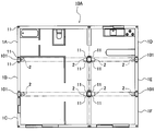
- the unit building 10B shown in FIG. 6 is a building in which clearances for floor plan adjustment are formed between the beam members on both the long side and the short side, and the building units 1A, 1B, 1B, 1C, 1D , 1E, 1E, and 1F are each formed with a gap 101 of about 20-30 cm, and a gap 102 of about 20-30 cm is provided between the building units 1A, 1D, 1B, 1E, 1C, and 1F. Are formed respectively.
- a connecting member 2 is arranged.
- the connecting member 2 is disposed between the facing ceiling beams 13 and 13 in the vicinity of the joint portion between the column 11 and the ceiling beam 13.
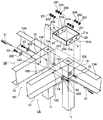
- the connecting member 2 includes a channel steel member 22 having a substantially C-shaped cross section, and a pair of end plates 21 formed by a steel plate so as to close the openings on both sides of the channel steel member 22. 21 mainly.
- the bottom surface of the grooved steel material 22 is a face material portion 222, and the portions bent upward at substantially right angles from both sides of the face material portion 222 are width direction side wall portions 221 and 221.
- end plate 21 is fixed to the edge portions of the face material portion 222 and the width direction side wall portions 221 and 221 by welding. Further, the end plate 21 is provided with a plurality of holes 21a into which the bolts 23 are inserted.
- the width direction side wall portions 221 and 221 of the channel steel material 22 are connected between the both end surfaces of the end plates 21 and 21. Further, between the both end surfaces of the end plates 21 and 21 are connected by the width direction side wall portions 221 and 221 of the channel steel material 22. Further, the inner surface of the rectangular outline in plan view formed by the end plates 21 and 21 and the width direction side wall portions 221 and 221 is closed by the face material portion 222 of the channel steel material 22.
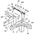
- the wrench 46 is fitted to the hexagonal portion 43a protruding outward from the insertion portion 41, and the connecting rod 430 is rotated.
- the insertion part 41 moves relatively to either direction of an axial direction with respect to the screw rod 43
- the insertion part 42 is the insertion part 41 with respect to the reverse screw rod 44. It moves relatively in the direction opposite to the moving direction. Accordingly, the building unit 1A and the building unit 1B move.
- the surface adjustment jig 4A the interval in the width direction of the gap 101 can be adjusted to the interval between the insertion portions 41 and 42.
- the ceiling beams 13 and 13 can be bent at places other than the place where the connecting members 2 and 2 are arranged, the ceiling beam 13 constituting the frame structure (frame structure) is connected to the connecting members 2 and 2 when a large earthquake occurs. It is possible to prevent damage such that the unit building 10A collapses by bending at the non-rigid portion and absorbing the earthquake energy by the deformation.
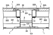
- the connecting member 2 can be attached by work from above. Further, if the spacer 24 is interposed between the end plate 21 as the beam side wall portion and the joint frame material 14 of the beam material, the gap 101 wider than the width of the connecting member 2 between the building units 1 and 1. Even if it is open, the connecting member 2 can be fixed in close contact with the joining frame member 14.
- the gap 101 is 20-30 cm wide, even if the cross joist 321 of the floor panel 32 is wood having a thickness of about 15-21 mm and a cross section of about 30-50 mm in width, The floor panel 32 can be installed across.
- This adjustment hole 5 is drilled between the holes 21a and 21a for inserting the bolts 23 of the end plate 21A. Moreover, the adjustment holes 5 and 5 are provided in each of a pair of opposing end plates 21A and 21A.
- an adjustment hole 134 as a position adjustment hole is provided in the ceiling beam 13 and the joint frame member 14 at a position where the connecting member 2 ⁇ / b> A is attached in accordance with a position facing the adjustment hole 5.
- the adjustment holes 134 and 134 are also provided in the facing ceiling beams 13 and 13 and the joint frame members 14 and 14 on both sides of the gap 101, respectively.
- a fine adjustment is performed by inserting and operating a sword 51 as a bar-shaped tool. become. That is, the relative positioning between the building units 1A and 1B is performed, and the entrance and exit of the columns 11 and 11 across the gap 101 are eliminated.
- the adjustment holes 5 and 134 are provided at the correct positions of the end plates 21A and 21A of the connecting member 2A and the ceiling beams 13 and 13 and the joint frame members 14 and 14 facing each other with the gap 101 therebetween.
- the relative positioning between the building units 1 ⁇ / b> A and 1 ⁇ / b> B can be performed using a rod-like tool such as the sushi 51, so that the entrance / exit of the side surfaces of the columns 11 and 11 across the gap 101 can be eliminated.
- the connecting member 2A can be temporarily supported by inserting a tool such as 51 in the adjustment holes 5 and 134, the bolt 23 and the nut 23 can be quickly mounted and tightened. become able to.
- a face material part is provided in an upper surface position or an intermediate position. It may be configured to be closed.
Landscapes
- Engineering & Computer Science (AREA)
- Architecture (AREA)
- Physics & Mathematics (AREA)
- Electromagnetism (AREA)
- Civil Engineering (AREA)
- Structural Engineering (AREA)
- Joining Of Building Structures In Genera (AREA)
Abstract
Description
[関連出願への相互参照]
本出願は、2011年3月1日に日本国特許庁に出願された特願2011-043616及び2011年9月14日に日本国特許庁に出願された特願2011-200065に基づいて優先権を主張し、その全ての開示は完全に本明細書で参照により組み込まれる。
Claims (8)
- 梁材と柱材とによって骨組みが形成される建物ユニットを複数、隣接させて構成されるユニット建物における、少なくとも一対の並設された建物ユニット間に形成された間取り調整用の隙間に連結部材が配置されるユニット建物の連結構造であって、
前記連結部材の配置箇所では前記建物ユニット間の前記梁材の長手方向及び前記隙間の幅方向の変形が拘束され、前記梁材の長手方向の前記連結部材間は前記梁材の長手方向及び前記隙間の幅方向の変形が許容されるように、前記隙間の対向する梁材間は、前記柱材との接合部の近傍となる両端で前記連結部材によって連結されるとともに、
前記連結部材は、前記隙間の対向する梁材のそれぞれに沿って延設される一対の梁側側壁部と、それらの梁側側壁部間を接続させる一対の幅方向側壁部と、前記梁側側壁部及び前記幅方向側壁部によって形成された外郭の内側を塞ぐ面材部とを備えていることを特徴とするユニット建物の連結構造。 - 前記梁側側壁部が、前記梁材の長手方向に間隔を置いて配置される複数のボルトによって前記梁材に固定されることを特徴とする請求項1に記載のユニット建物の連結構造。
- 前記幅方向側壁部と前記面材部とは、溝形鋼材によって一体に形成されるとともに、前記梁側側壁部は、前記溝形鋼材の側面を塞ぐエンドプレートによって形成されることを特徴とする請求項1又は2に記載のユニット建物の連結構造。
- 前記面材部は、前記連結部材の下面を形成することを特徴とする請求項1乃至3のいずれか一項に記載のユニット建物の連結構造。
- 前記梁側側壁部及びそれを固定させる前記梁材に位置調整用の穴が設けられることを特徴とする請求項1乃至4のいずれか一項に記載のユニット建物の連結構造。
- 前記梁側側壁部と前記梁材との間にスペーサを介在させることを特徴とする請求項1乃至5のいずれか一項に記載のユニット建物の連結構造。
- 前記柱材と前記梁材とはそれぞれの側面に当接させる当接面を備えた接合枠材を介して接合されており、前記連結部材は前記接合枠材を介して前記梁材に固定されることを特徴とする請求項1乃至6のいずれか一項に記載のユニット建物の連結構造。
- 前記隙間は20-30cmの幅であって、前記隙間の上方には、前記建物ユニットの床梁となる梁材間に跨って床パネルが設置されることを特徴とする請求項1乃至7のいずれか一項に記載のユニット建物の連結構造を備えたユニット建物。
Priority Applications (1)
| Application Number | Priority Date | Filing Date | Title |
|---|---|---|---|
| KR1020137023509A KR20130122790A (ko) | 2011-03-01 | 2011-11-04 | 유닛 건물의 연결 구조 및 유닛 건물 |
Applications Claiming Priority (4)
| Application Number | Priority Date | Filing Date | Title |
|---|---|---|---|
| JP2011043616 | 2011-03-01 | ||
| JP2011-043616 | 2011-03-01 | ||
| JP2011-200065 | 2011-09-14 | ||
| JP2011200065A JP5903232B2 (ja) | 2011-03-01 | 2011-09-14 | ユニット建物の連結構造及びユニット建物 |
Publications (1)
| Publication Number | Publication Date |
|---|---|
| WO2012117615A1 true WO2012117615A1 (ja) | 2012-09-07 |
Family
ID=46757564
Family Applications (1)
| Application Number | Title | Priority Date | Filing Date |
|---|---|---|---|
| PCT/JP2011/075452 Ceased WO2012117615A1 (ja) | 2011-03-01 | 2011-11-04 | ユニット建物の連結構造及びユニット建物 |
Country Status (3)
| Country | Link |
|---|---|
| JP (1) | JP5903232B2 (ja) |
| KR (1) | KR20130122790A (ja) |
| WO (1) | WO2012117615A1 (ja) |
Families Citing this family (4)
| Publication number | Priority date | Publication date | Assignee | Title |
|---|---|---|---|---|
| JP6019176B2 (ja) * | 2011-03-01 | 2016-11-02 | 積水化学工業株式会社 | ユニット建物の連結構造及びユニット建物 |
| JP6581375B2 (ja) * | 2015-03-26 | 2019-09-25 | 積水化学工業株式会社 | 建物ユニットの連結構造及び建物ユニットの連結方法 |
| JP6693713B2 (ja) * | 2015-07-02 | 2020-05-13 | 積水化学工業株式会社 | 位置調整構造 |
| KR101705260B1 (ko) * | 2016-11-17 | 2017-02-22 | 한국건설기술연구원 | 모듈러건축물의 코아구조물과 모듈러구조물의 연결구조 및 그 시공방법 |
Citations (2)
| Publication number | Priority date | Publication date | Assignee | Title |
|---|---|---|---|---|
| JP2005023665A (ja) * | 2003-07-03 | 2005-01-27 | Misawa Homes Co Ltd | ユニット式建物 |
| JP2009174247A (ja) * | 2008-01-28 | 2009-08-06 | Sekisui Chem Co Ltd | ユニット建物の連結構造及びユニット建物 |
Family Cites Families (3)
| Publication number | Priority date | Publication date | Assignee | Title |
|---|---|---|---|---|
| JPS5419044Y2 (ja) * | 1975-05-30 | 1979-07-16 | ||
| JP2680495B2 (ja) * | 1991-11-28 | 1997-11-19 | ミサワホーム株式会社 | 住戸ユニットからなる建築物 |
| JPH09209451A (ja) * | 1996-02-07 | 1997-08-12 | Daiwa House Ind Co Ltd | 上下柱と梁の接合構造および接合方法 |
-
2011
- 2011-09-14 JP JP2011200065A patent/JP5903232B2/ja active Active
- 2011-11-04 WO PCT/JP2011/075452 patent/WO2012117615A1/ja not_active Ceased
- 2011-11-04 KR KR1020137023509A patent/KR20130122790A/ko not_active Ceased
Patent Citations (2)
| Publication number | Priority date | Publication date | Assignee | Title |
|---|---|---|---|---|
| JP2005023665A (ja) * | 2003-07-03 | 2005-01-27 | Misawa Homes Co Ltd | ユニット式建物 |
| JP2009174247A (ja) * | 2008-01-28 | 2009-08-06 | Sekisui Chem Co Ltd | ユニット建物の連結構造及びユニット建物 |
Also Published As
| Publication number | Publication date |
|---|---|
| JP5903232B2 (ja) | 2016-04-13 |
| KR20130122790A (ko) | 2013-11-08 |
| JP2012193599A (ja) | 2012-10-11 |
Similar Documents
| Publication | Publication Date | Title |
|---|---|---|
| JP6394239B2 (ja) | 連結柱 | |
| JP6990979B2 (ja) | 建築物の架構構造 | |
| JP5903232B2 (ja) | ユニット建物の連結構造及びユニット建物 | |
| JP6019176B2 (ja) | ユニット建物の連結構造及びユニット建物 | |
| JP4729055B2 (ja) | ユニット建物の連結構造及びユニット建物 | |
| JP5967438B2 (ja) | ブレース耐震補強構造 | |
| JP6581375B2 (ja) | 建物ユニットの連結構造及び建物ユニットの連結方法 | |
| JP6124444B2 (ja) | 構造物解体システム | |
| JP2016017323A (ja) | 制震構造 | |
| JP5400283B2 (ja) | 建物ユニットの連結構造及びユニット建物 | |
| JP6138437B2 (ja) | ユニット建物 | |
| JP4690810B2 (ja) | 大梁と小梁の接合施工方法および接合構造 | |
| JP2006291531A (ja) | 柱・梁接合部構造 | |
| JP6669088B2 (ja) | 鋼板耐震壁、耐震フレームおよびこれを備えた建物 | |
| JP2018115491A (ja) | 建物構造 | |
| JP6664208B2 (ja) | 梁と柱の接合構造 | |
| JP6565543B2 (ja) | 柱及び梁の接合構造、柱及び梁の接合構造を備えた建物 | |
| JP7358142B2 (ja) | ユニット建物 | |
| JP7495309B2 (ja) | 梯子型耐力壁架構及び門型架構 | |
| JP6301229B2 (ja) | ユニット建物の防振構造及びその構築方法 | |
| JP7496219B2 (ja) | 建物ユニット調整治具の配置構造 | |
| JP5612832B2 (ja) | ユニット建物 | |
| JP5612845B2 (ja) | ユニット建物及び局所フレーム | |
| JP6278644B2 (ja) | 接合構造 | |
| JP2020147986A (ja) | 建物ユニットの連結構造 |
Legal Events
| Date | Code | Title | Description |
|---|---|---|---|
| 121 | Ep: the epo has been informed by wipo that ep was designated in this application |
Ref document number: 11859791 Country of ref document: EP Kind code of ref document: A1 |
|
| WWE | Wipo information: entry into national phase |
Ref document number: 1301004819 Country of ref document: TH |
|
| NENP | Non-entry into the national phase |
Ref country code: DE |
|
| ENP | Entry into the national phase |
Ref document number: 20137023509 Country of ref document: KR Kind code of ref document: A |
|
| 122 | Ep: pct application non-entry in european phase |
Ref document number: 11859791 Country of ref document: EP Kind code of ref document: A1 |