WO2012115160A1 - 表示装置 - Google Patents
表示装置 Download PDFInfo
- Publication number
- WO2012115160A1 WO2012115160A1 PCT/JP2012/054302 JP2012054302W WO2012115160A1 WO 2012115160 A1 WO2012115160 A1 WO 2012115160A1 JP 2012054302 W JP2012054302 W JP 2012054302W WO 2012115160 A1 WO2012115160 A1 WO 2012115160A1
- Authority
- WO
- WIPO (PCT)
- Prior art keywords
- image
- gradation data
- pixel
- observer
- unit
- Prior art date
- Legal status (The legal status is an assumption and is not a legal conclusion. Google has not performed a legal analysis and makes no representation as to the accuracy of the status listed.)
- Ceased
Links
Images






Classifications
-
- G—PHYSICS
- G09—EDUCATION; CRYPTOGRAPHY; DISPLAY; ADVERTISING; SEALS
- G09G—ARRANGEMENTS OR CIRCUITS FOR CONTROL OF INDICATING DEVICES USING STATIC MEANS TO PRESENT VARIABLE INFORMATION
- G09G3/00—Control arrangements or circuits, of interest only in connection with visual indicators other than cathode-ray tubes
- G09G3/001—Control arrangements or circuits, of interest only in connection with visual indicators other than cathode-ray tubes using specific devices not provided for in groups G09G3/02 - G09G3/36, e.g. using an intermediate record carrier such as a film slide; Projection systems; Display of non-alphanumerical information, solely or in combination with alphanumerical information, e.g. digital display on projected diapositive as background
- G09G3/003—Control arrangements or circuits, of interest only in connection with visual indicators other than cathode-ray tubes using specific devices not provided for in groups G09G3/02 - G09G3/36, e.g. using an intermediate record carrier such as a film slide; Projection systems; Display of non-alphanumerical information, solely or in combination with alphanumerical information, e.g. digital display on projected diapositive as background to produce spatial visual effects
-
- G—PHYSICS
- G02—OPTICS
- G02B—OPTICAL ELEMENTS, SYSTEMS OR APPARATUS
- G02B30/00—Optical systems or apparatus for producing three-dimensional [3D] effects, e.g. stereoscopic images
- G02B30/20—Optical systems or apparatus for producing three-dimensional [3D] effects, e.g. stereoscopic images by providing first and second parallax images to an observer's left and right eyes
- G02B30/26—Optical systems or apparatus for producing three-dimensional [3D] effects, e.g. stereoscopic images by providing first and second parallax images to an observer's left and right eyes of the autostereoscopic type
- G02B30/30—Optical systems or apparatus for producing three-dimensional [3D] effects, e.g. stereoscopic images by providing first and second parallax images to an observer's left and right eyes of the autostereoscopic type involving parallax barriers
-
- H—ELECTRICITY
- H04—ELECTRIC COMMUNICATION TECHNIQUE
- H04N—PICTORIAL COMMUNICATION, e.g. TELEVISION
- H04N13/00—Stereoscopic video systems; Multi-view video systems; Details thereof
- H04N13/10—Processing, recording or transmission of stereoscopic or multi-view image signals
- H04N13/106—Processing image signals
- H04N13/122—Improving the three-dimensional [3D] impression of stereoscopic images by modifying image signal contents, e.g. by filtering or adding monoscopic depth cues
-
- G—PHYSICS
- G09—EDUCATION; CRYPTOGRAPHY; DISPLAY; ADVERTISING; SEALS
- G09G—ARRANGEMENTS OR CIRCUITS FOR CONTROL OF INDICATING DEVICES USING STATIC MEANS TO PRESENT VARIABLE INFORMATION
- G09G2320/00—Control of display operating conditions
- G09G2320/02—Improving the quality of display appearance
- G09G2320/0209—Crosstalk reduction, i.e. to reduce direct or indirect influences of signals directed to a certain pixel of the displayed image on other pixels of said image, inclusive of influences affecting pixels in different frames or fields or sub-images which constitute a same image, e.g. left and right images of a stereoscopic display
-
- G—PHYSICS
- G09—EDUCATION; CRYPTOGRAPHY; DISPLAY; ADVERTISING; SEALS
- G09G—ARRANGEMENTS OR CIRCUITS FOR CONTROL OF INDICATING DEVICES USING STATIC MEANS TO PRESENT VARIABLE INFORMATION
- G09G2320/00—Control of display operating conditions
- G09G2320/02—Improving the quality of display appearance
- G09G2320/0285—Improving the quality of display appearance using tables for spatial correction of display data
-
- H—ELECTRICITY
- H04—ELECTRIC COMMUNICATION TECHNIQUE
- H04N—PICTORIAL COMMUNICATION, e.g. TELEVISION
- H04N13/00—Stereoscopic video systems; Multi-view video systems; Details thereof
- H04N13/30—Image reproducers
- H04N13/302—Image reproducers for viewing without the aid of special glasses, i.e. using autostereoscopic displays
- H04N13/305—Image reproducers for viewing without the aid of special glasses, i.e. using autostereoscopic displays using lenticular lenses, e.g. arrangements of cylindrical lenses
-
- H—ELECTRICITY
- H04—ELECTRIC COMMUNICATION TECHNIQUE
- H04N—PICTORIAL COMMUNICATION, e.g. TELEVISION
- H04N13/00—Stereoscopic video systems; Multi-view video systems; Details thereof
- H04N13/30—Image reproducers
- H04N13/302—Image reproducers for viewing without the aid of special glasses, i.e. using autostereoscopic displays
- H04N13/31—Image reproducers for viewing without the aid of special glasses, i.e. using autostereoscopic displays using parallax barriers
Definitions
- the present invention relates to a display device that can suppress the occurrence of crosstalk.
- a display device that uses a parallax barrier to separate a plurality of images included in a composite image displayed on a display panel so that they can be viewed from different directions.
- display devices described in International Publication No. 2007-32132 and Japanese Patent Application Laid-Open No. 2004-31780 correspond to this. These display devices are put into practical use as, for example, a stereoscopic display of a digital camera, a vehicle-mounted dual view display device, and the like.
- An object of the present invention is to provide a display device that can suppress the occurrence of crosstalk.
- the display device of the present invention divides a plurality of different images from each other, displays a composite image formed by arranging these divided images in a predetermined order, and the plurality of images included in the composite image
- a separation unit that separates an image
- a correction unit that corrects gradation data of a pixel that displays an image that should originally be viewed by an observer among the plurality of images included in the composite image.
- a generation unit that generates factor gradation data that causes crosstalk based on gradation data of pixels that display an image other than an image that should originally be viewed by the observer among the plurality of images included in the composite image
- a determination unit that determines a correction amount to be used when correcting the gradation data using the factor gradation data.
- FIG. 2 is a schematic diagram for explaining pixels that cause crosstalk in the display device shown in FIG. 1.
- FIG. 1 is a schematic diagram which shows an example of schematic structure of the display apparatus as the application example 2 of the 1st Embodiment of this invention.
- FIG. 1 is a schematic diagram which shows an example of schematic structure of the display apparatus as the application example 2 of the 1st Embodiment of this invention.
- FIG. 1 is a schematic diagram which shows an example of schematic structure of the display apparatus as the application example 2 of the 1st Embodiment of this invention.
- a display device divides a plurality of different images from each other, displays a composite image formed by arranging these divided images in a predetermined order, and the composite image
- a separation unit that separates the plurality of images included, and a correction unit that corrects gradation data of pixels that display an image that should be originally viewed by the observer among the plurality of images included in the composite image
- the correction unit is factor grayscale data that causes crosstalk based on grayscale data of a pixel that displays an image other than the image that should originally be viewed by the observer among the plurality of images included in the composite image.
- a determination unit that determines a correction amount to be used when correcting the gradation data using the factor gradation data.
- the gradation data of the pixel that originally displays an image that should be viewed by the observer is a pixel that displays an image other than the image that should originally be viewed by the observer among a plurality of images included in the composite image. Correction is performed based on the gradation data. As a result, appropriate crosstalk correction can be performed.
- the gradation data of a pixel that displays an image that the observer should originally view is I X
- the factor gradation data is I Y
- the image that the observer should originally see the maximum value of the gradation data of the pixel to be displayed as a I M and the crosstalk level is C
- the gray scale data of the pixel which is corrected by the correction unit in case of a I O
- the correction unit is configured to correct the gradation data of the pixel that displays the image that the observer should originally see by the following equation (2).
- I O I X + D
- the generation unit is a pixel level that displays an image other than an image that should be viewed by an observer among the plurality of images included in the composite image.
- the factor gradation data is generated by averaging the tone data. In such a configuration, factor gradation data can be easily generated.
- the generation unit is a pixel level that displays an image other than an image that should be viewed by an observer among the plurality of images included in the composite image.
- the factor grayscale data is generated by multiplying the contribution ratio of the pixel to the crosstalk and summing them.
- appropriate factor gradation data can be generated. As a result, more appropriate crosstalk correction can be performed.
- the generation unit has a relationship between gradation data of pixels that display an image other than an image that should be viewed by an observer, and the factor gradation data.
- the generation unit uses the gradation data of pixels that display an image other than the image that the observer should originally view, and the factor gradation data using the lookup table. It is the structure to generate.
- appropriate factor gradation data can be stored in the lookup table. As a result, more appropriate crosstalk correction can be performed.
- a sixth configuration is the parallax barrier according to any one of the first to fifth configurations, wherein the separation unit separates the plurality of images included in the composite image so as to be seen from different directions. It is the structure which is done.
- a seventh configuration is the lenticular lens according to any one of the first to fifth configurations, wherein the separation unit separates the plurality of images included in the composite image so as to be seen from different directions. It is the structure which is done.
- An eighth configuration is the liquid crystal lens according to any one of the first to fifth configurations, wherein the separation unit separates the plurality of images included in the composite image so as to be seen from different directions. It is the structure which is done.
- the separation unit separates the plurality of images included in the composite image so as to be viewed from different directions. It is the structure made into the board.
- the generation unit is a pixel that displays an image that should be viewed by an observer, and a display area in which the composite image is displayed
- the factor gradation data is generated using the assumed gradation data. In such a configuration, factor gradation data can be generated even for pixels located at the edge of the display area.
- An eleventh configuration according to any one of the first to tenth configurations further includes a conversion unit that converts the gradation data into data of a predetermined bit, and uses the data converted by the conversion unit.
- the correction unit corrects the gradation data.
- the gradation data can be easily corrected even if the gradation data is not a gradation value, for example, a voltage value or a luminance value.
- each figure referred below demonstrates the simplified main component required in order to demonstrate this invention among the structural members of embodiment of this invention for convenience of explanation. Therefore, the display device according to the present invention can include arbitrary constituent members that are not shown in the drawings referred to in this specification. Moreover, the dimension of the member in each figure does not represent the dimension of an actual structural member, the dimension ratio of each member, etc. faithfully.
- FIG. 1 shows a display device 10 as a first embodiment of the present invention.
- the display device 10 includes a display panel 12, a barrier unit 14, and a backlight 16.
- the display panel 12 is a liquid crystal panel.
- the display panel 12 includes an active matrix substrate 18 in which a plurality of pixel electrodes are formed in a matrix, a counter substrate 20 on which counter electrodes are formed, and a space between the active matrix substrate 18 and the counter substrate 20. And a liquid crystal layer 22 encapsulated therein.
- a pixel is formed including the pixel electrode.
- a region where a plurality of pixels are formed in a matrix is a display region of the display panel 12. In the present embodiment, as illustrated in FIG. 1, the columns of the pixels R that display the image for the right eye and the columns of the pixels L that display the image for the left eye are alternately arranged.
- the right-eye image and the left-eye image are each divided into pixel columns (in a stripe shape). Then, a composite image obtained by alternately arranging the right eye image and the left eye image divided in the stripe shape is displayed on the display panel 12.
- a color filter layer is formed on one of the active matrix substrate 18 and the counter substrate 20. Thereby, color characteristics are given to each pixel.
- a backlight 16 is disposed on one side in the thickness direction of the display panel 12.
- the backlight 16 includes a light source 24 and a reflection unit 26.
- the backlight 16 in addition to the edge light type as shown in FIG. 1, for example, a direct type, a planar light source type, or the like can be adopted. Moreover, as the light source 24 of the backlight 16, a cold cathode tube, a light emitting diode (LED), etc. are employable, for example.
- a barrier unit 14 is disposed on the other side in the thickness direction of the display panel 12.
- the barrier unit 14 is disposed to perform light shielding / transmission (separation of irradiation light from the backlight 16), and does not need to be disposed on the other side in the thickness direction of the display panel 12. .
- it may be disposed between the display panel 12 and the backlight 16.
- the barrier unit 14 includes a substrate 28.
- a substrate 28 for example, a glass substrate or the like can be employed.
- the barrier unit 14 further includes a plurality of light shielding layers 30.
- a photosensitive resin containing a black pigment can be employed as the light shielding layer 30, for example.
- the plurality of light shielding layers 30 are formed in stripes corresponding to the columns of the pixels R and L included in the active matrix substrate 18.
- the barrier portion 14 is formed with a light transmitting slit 32 between two adjacent light shielding layers 30 and 30. That is, the barrier unit 14 includes a parallax barrier 34 as a separation unit in which the light shielding layers 30 and the light transmitting slits 32 are alternately arranged.
- Each light shielding layer 30 shields a part of the light irradiated from the backlight 16 and transmitted through the display panel 12.
- the row of pixels R displaying the right-eye image can be observed with the observer's right eye, but cannot be observed with the observer's left eye.
- the column of pixels L displaying the left-eye image can be observed with the left eye of the observer, but cannot be observed with the right eye of the observer.
- the observer can see a stereoscopic image.
- the barrier unit 14 further includes a resin layer 36.
- a resin layer 36 for example, an ultraviolet curable resin or the like can be used.
- the resin layer 36 is formed on the substrate 28 so as to cover the light shielding layer 30.
- the resin layer 36 bonds the barrier unit 14 and the display panel 12 together.
- the polarizing plate 38a disposed on the active matrix substrate 18 side is attached to the active matrix substrate 18, and the polarizing plate 38b disposed on the counter substrate 20 side has the barrier unit 14. Affixed to the substrate 28.
- the display device 10 includes a gate driver 40, a source driver 42, and a display control unit 44 as a drive control unit for the display panel 12.
- a plurality of gate lines 46 are connected to the gate driver 40. Each of the plurality of gate lines 46 is connected to a gate electrode of a thin film transistor as a switching element.
- the thin film transistor is formed on the active matrix substrate 18.
- Each gate line 46 transmits a scanning signal output from the gate driver 40.
- the thin film transistor is driven and controlled by a scanning signal input to the gate electrode.
- a plurality of source lines 48 are connected to the source driver 42. Each of the plurality of source lines 48 is connected to the source electrode of the thin film transistor. Each source line 48 transmits a display signal output from the source driver 42.
- a display signal is input to the thin film transistor under the driving state of the thin film transistor, charges corresponding to the display signal are accumulated in a storage capacitor connected to the thin film transistor.
- the storage capacitor is realized by a pixel electrode connected to the drain electrode of the thin film transistor, a counter electrode disposed to face the pixel electrode, and a liquid crystal layer 22 positioned between the pixel electrode and the counter electrode. By accumulating charges corresponding to the display signal in the storage capacitor, the gradation of each pixel can be controlled. As a result, an image can be displayed on the display panel 12.
- the display control unit 44 generates various signals necessary for image display based on a display data signal and a timing control signal sent from the outside, and outputs them to the gate driver 40 and the source driver 42.
- the above composite image is generated in the display control unit 44.
- the display unit is realized by the display panel 12 and the drive control unit (the gate driver 40, the source driver 42, and the display control unit 44) of the display panel 12.
- the display control unit 44 includes a memory 50 and a correction unit 52 as shown in FIG.
- the memory 50 temporarily stores display data signals sent from the outside.
- only one memory 50 is provided.
- a memory for temporarily storing a display data signal for displaying is not necessary to provide a memory.
- the correction unit 52 corrects the gradation data (in this embodiment, the gradation value) of the pixel that displays the image that should be originally viewed by the observer among the plurality of images included in the composite image. Thereby, occurrence of crosstalk can be suppressed.
- Crosstalk is a phenomenon in which an image other than an image that should be viewed by an observer can be seen among a plurality of images included in a composite image. Crosstalk is caused by, for example, multiple reflections between layers in the display device 10 or light leakage from the light shielding layer 30 of the parallax barrier 34.
- the correction unit 52 includes a generation unit 54, a determination unit 56, and a calculation unit 58.
- the generation unit 54 generates factor grayscale data that causes crosstalk based on the grayscale data of a pixel that displays an image other than an image that should be viewed by the observer among a plurality of images included in the composite image. To do. Pixels that cause crosstalk differ depending on, for example, the positional relationship between the light shielding layer of the parallax barrier and the light transmitting slit.
- the pixels that cause crosstalk are These pixels are located on both sides in the left-right direction of the display screen of the display device 10 with respect to the pixels that originally display an image to be viewed by the observer.
- the pixels that cause crosstalk are adjacent to each other in the row direction with respect to the pixels that display an image that should be viewed by the observer among the plurality of pixels formed in a matrix. It is a pixel located.
- I'Rn (I Rn ⁇ 1 + I Rn ) / 2 (3)
- I Rn ⁇ 1 is the gradation data of the pixel R n ⁇ 1
- I Rn is the gradation data of the pixel R n .
- the ranges of I Rn ⁇ 1 and I Rn are 0 to 255, respectively.
- the determination unit 56 determines the correction amount using the factor gradation data generated by the generation unit 54.
- the correction amount is used when correcting the gradation data.
- D Ln K ⁇ (I M ⁇ I Ln ⁇ I ′ Rn ⁇ 1) / (I M +1) (4)
- I M is the maximum value of the gradation data.
- I M becomes 255.
- I Ln is the gradation data of the pixel Ln.
- the range of ILn is 0 to 255.
- K is a value obtained by adding 1 to the crosstalk level C (described later).
- the calculation unit 58 corrects the gradation data of the pixel using the correction amount determined by the determination unit 56.
- the corrected gradation data Io Ln of the pixel Ln shown in FIG. 4 is obtained by the following equation (5).
- Io Ln I Ln + D Ln (5)
- each pixel has a plurality of sub-pixels (for example, a red pixel, a green pixel, and a blue pixel)
- the factor gradation data, the correction amount, and the corrected gradation data are generated for each sub-pixel.
- the generation unit 54 generates factor gradation data for pixels that display an image that the viewer should originally view and that are located at the edge of a display area (not shown) in which the composite image is displayed.
- the gradation data of pixels that display an image other than the image that the observer originally should see and that do not exist is assumed, and factor gradation data is generated using the assumed gradation data.
- a method of assuming gradation data of pixels that do not exist originally for example, pixels that display an image other than the image that the viewer should originally see, and the gradation data of pixels that actually exist are represented by appropriate numerical values (for example, The method of dividing by 2) can be employed.
- a method of dividing the average value of gradation data of these pixels by an appropriate numerical value can be employed.
- the gradation data of the pixel entering the left eye is expressed by the following equation (6).
- I L of the tone data of the pixels entering the left eye
- F ⁇ I R of the tone data of the pixels entering the left eye
- F ⁇ I R is obtained by multiplying the crosstalk ratio F to the gradation data I R of the pixel R for displaying a right eye image.
- the range of F is 0-1.
- F is, for example, the distance between two adjacent light shielding layers 30 and 30 in the parallax barrier 34, the shape of the light shielding layer 30, the material of the light shielding layer 30, the formation position of the light shielding layer 30, the width of the light shielding layer 30, Due to the thickness, the positional relationship between the light shielding layer 30 and the pixels R and L, and the like, the display device 10 is different.
- F can be obtained by measurement for each display device 10.
- a measuring method of F for example, the luminance of a pixel that enters the left eye is measured when the pixel that displays the image for the left eye is displayed in black and the pixel that displays the image for the right eye is displayed in white.
- the luminance of the pixel that enters the left eye is measured and calculated from the difference between these luminances. Can be adopted.
- F can also be expressed as C / I M.
- C is a crosstalk level.
- the range of C is 0 to 255. It expressed the F as C / I M, equation (6) is as follows. I L + (C / I M ) ⁇ I R (6 ′)
- the corrected gradation data can be expressed as the following formula (8).
- Ib I L ⁇ ((I M ⁇ C) / I M ) + C (9)
- Equation (10) The approximation of Equation (10) is performed by adding 1 to Io, I M , I L , I R and C.
- the corrected gradation data calculated by the calculation unit 58 is expressed by Expression (12) or Expression (13).
- the correction amount determined by the determination unit 56 is expressed by the second term of Expression (12) or Expression (13).
- Factors tone data generated by the generating unit 54 is a I R contained in the second term of formula (12) or Formula 13.
- the above equations (6) to (13) are for correcting the gradation data of the pixel L that displays the image for the left eye, but the gradation data of the pixel R that displays the image for the right eye.
- the factor gradation data is the average of the gradation data of the pixels located on both the left and right sides of the pixel that originally displays the image to be viewed by the observer. Therefore, the factor gradation data is easily generated. can do.
- a n-1 and A n are, for example, the distance between two adjacent light shielding layers 30 and 30 in the parallax barrier 34, the shape of the light shielding layer 30, the position where the light shielding layer 30 is formed, the width of the light shielding layer 30, and the light shielding layer. Due to the positional relationship between the pixel 30 and the pixels R and L, etc., the display device differs for each display device. A n ⁇ 1 and A n can be obtained by measuring each display device.
- a measurement method for example, when all pixels (pixel L n , pixel R n, and pixel R n-1 ) are displayed in black, the luminance of the pixel entering the left eye and the pixel to be measured are displayed in white In this state, when the remaining pixels are displayed in black, the luminance of the pixels entering the left eye is measured, and a method of calculating from the difference between these luminances can be employed.
- the above equation (14) is for correcting the gradation data of the pixel L that displays the image for the left eye, but when correcting the gradation data of the pixel R that displays the image for the right eye.
- R and L need only be changed. Therefore, detailed description of the case where the gradation data of the pixel R that displays the right-eye image is corrected will be omitted.
- the factor gradation data is obtained by using the contribution ratio to the crosstalk of the pixels located on both sides of the pixel that displays the image that the observer should originally view.
- the factor gradation data is obtained on the assumption that the contribution ratio to the crosstalk of the pixels located on both sides of the pixel that displays the image that the observer should originally view is the same (in the case of the first embodiment).
- more appropriate factor gradation data can be obtained.
- the accuracy of crosstalk correction can be further improved.
- a lenticular lens 60 as a separation unit is arranged instead of the barrier unit 14.
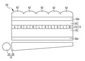
- the lenticular lens 60 is a lens in which a plurality of cylindrical lenses 62 are arranged in a direction in which rows of pixels R and rows of pixels L are alternately arranged.
- the lenticular lens 60 is attached to the polarizing plate 38b disposed on the counter substrate 20 side so that each cylindrical lens 62 corresponds to the row of the pixels R and L.
- the polarizing plate 38 b disposed on the counter substrate 20 side is attached to the counter substrate 20.
- the pixel R and the pixel L are located next to each other not only in the horizontal direction of the display panel 12 but also in the vertical direction of the display panel 12.
- the light shielding layer 30 is formed so as to leave a gap of one pixel in the vertical direction of the display panel 12.
- the light shielding layer 30 can be made harder to see than when the light shielding layer 30 is formed in a stripe shape.
- the pixels located on both sides in the left-right direction of the display panel 12 cause crosstalk.
- the pixel R (n, m) shown in FIG. 6 the pixel R (n, m ⁇ 1) and the pixel R (n, m + 1) located on both sides in the left-right direction of the display panel 12,
- the pixel R (n + 1, m) and the pixel R (n-1, m) located on both sides in the vertical direction cause crosstalk.
- the factor gradation data I ′ R used when correcting the crosstalk of the pixel L (n, m) is obtained by the following equation (15).
- I'R (I R (n , m-1) + I R (n, m + 1) + I R (n + 1, m) + I R (n-1, m)) / 4 ⁇
- I R (n, m ⁇ 1) is the gradation data of the pixel R (n, m ⁇ 1).
- I R (n, m + 1) is the gradation data of the pixel R (n, m + 1).
- I R (n + 1, m) is the gradation data of the pixel R (n + 1, m).
- I R (n ⁇ 1, m) is the gradation data of the pixel R (n ⁇ 1, m).
- the factor gradation data I ′ R used when correcting the crosstalk of the pixel L (n, m) may be obtained by the following equation (16).
- I ′ R A (n, m ⁇ 1) ⁇ I R (n, m ⁇ 1) + A (n, m + 1) ⁇ I R (n, m + 1) + A (n + 1, m) ⁇ I R (n + 1, m) + A (n ⁇ 1, m) ⁇ I R (n ⁇ 1, m) (16)
- a (n, m ⁇ 1) is a contribution ratio of the pixel R (n, m ⁇ 1) to the crosstalk.
- a (n, m + 1) is a contribution rate of the pixel R (n, m + 1) to the crosstalk.
- a (n + 1, m) is a contribution ratio of the pixel R (n + 1, m) to the crosstalk.
- a (n ⁇ 1, m) is a contribution ratio of the pixel R (n ⁇ 1, m) to the crosstalk.
- the ranges of A (n, m ⁇ 1), A (n, m + 1), A (n + 1, m), and A (n ⁇ 1, m) are 0 to 1, respectively.
- a (n, m ⁇ 1), A (n, m + 1), A (n + 1, m), and A (n ⁇ 1, m) are, for example, an interval between two adjacent light shielding layers 30 and 30 and light shielding. Due to the shape of the layer 30, the formation position of the light shielding layer 30, the width of the light shielding layer 30, the positional relationship between the light shielding layer 30 and the pixels R and L, and the like, it differs for each display device. A (n, m ⁇ 1), A (n, m + 1), A (n + 1, m), and A (n ⁇ 1, m) can be obtained by measurement for each display device.
- a measuring method for example, all the pixels (pixel L (n, m), pixel R (n, m ⁇ 1), pixel R (n, m + 1), pixel R (n + 1, m) and pixel R (n ⁇ 1, m)), the luminance of the pixel that enters the left eye when displaying black, and the pixel that enters the left eye when displaying the remaining pixels in black with the pixel to be measured displayed in white It is possible to adopt a method of measuring the brightness of the light and calculating from the difference of the brightness.
- the above equations (15) and (16) are for correcting the gradation data of the pixel L that displays the image for the left eye, but the gradation data of the pixel R that displays the image for the right eye.
- a liquid crystal panel 64 is provided instead of the barrier unit 14.
- the liquid crystal panel 64 has a structure in which a liquid crystal layer 68 is sealed between a pair of substrates 66 and 66.
- the refractive index of the liquid crystal layer 68 partially changes.
- a liquid crystal lens as a separation unit is realized.
- FIG. 8 a partial retardation film 70 is arranged instead of the barrier unit 14. That is, this application example relates to a polarized glasses type stereoscopic display device.
- the partial phase difference plate 70 is formed by alternately arranging phase difference portions 72 and non-phase difference portions 74.
- the phase difference unit 72 is a half-wave plate and rotates the polarization direction of incident light (linearly polarized light) by 90 degrees.
- the pixel L that displays the image for the left eye is visible to the observer through the phase difference unit 72
- the pixel R that displays the image for the right eye is visible to the observer through the non-phase difference unit 74.
- the observer can see the left-eye image only with the left eye and can see the right-eye image with only the right eye.
- the correction unit 52 includes a changing unit 78.
- the change unit 78 is disposed between the memory 50 and the generation unit 54, for example.
- the changing unit 78 represents the 256 gradation (8 bits) in order to represent these voltage value and luminance value by a predetermined bit ( For example, it can be handled as 10-bit or 16-bit data.
- the correction unit 52 corrects the gradation data using the data changed by the changing unit 78.
- the gradation data can be easily corrected.
- the generation unit 54 includes a lookup table 80.
- the look-up table 80 shows the relationship between the gradation data of pixels that display an image other than the image that the observer should originally see and the factor gradation data.
- the look-up table 80 for example, the difference between the gradation data of pixels that display an image other than the image that the observer should originally see and that are located on both sides of the pixel that displays the image that the observer should originally see.
- a value and factor gradation data corresponding to the difference value are stored.
- the display device of the present embodiment is different in the number of viewpoints compared to the display device 10 of the first embodiment.
- the display device 10 of the first embodiment is a one-view stereoscopic display device
- the display device of the present embodiment is a four-view stereoscopic display device as shown in FIG.
- an image displayed in a direction different from the specific direction is recognized as crosstalk.
- the image is recognized as crosstalk.
- the image is recognized as crosstalk.
- the pixels that cause crosstalk of a certain pixel are four pixels located on the left side of the pixel and four pixels located on the right side of the pixel.
- the pixels that cause the crosstalk of the pixel P (n) 5 shown in FIG. 11 are four pixels P (n) 1, P (n) 2, P ( n) 3, P (n) 4, and four pixels P (n + 1) 1, P (n + 1) 2, P (n + 1) 3, P (n + 1) 4 located on the right side of the pixel P (n) 5.
- the factor gradation data I ′ n 5 used when correcting the crosstalk of the pixel P (n) 5 is obtained by the following equation (17).
- I ′ (n) 5 A (n) 1 ⁇ I (n) 1 + A (n) 2 ⁇ I (n) 2 + A (n) 3 ⁇ I (n) 3 + A (n) 4 ⁇ I (n) 4 + A (n + 1) ) 1 ⁇ I (n + 1) 1 + A (n + 1) 2 ⁇ I (n + 1) 2 + A (n + 1) 3 ⁇ I (n + 1) 3 + A (n + 1) 4 ⁇ I (n + 1) 4 (17)
- a (n) 1 indicates the contribution rate of the pixel P (n) 1 to the crosstalk.
- a (n) 2 indicates the contribution ratio of the pixel P (n) 2 to the crosstalk.
- a (n) 3 indicates the contribution ratio of the pixel P (n) 3 to the crosstalk.
- a (n) 4 indicates the contribution rate of the pixel P (n) 4 to the crosstalk.
- a (n + 1) 1 indicates the contribution ratio of the pixel P (n + 1) 1 to the crosstalk.
- a (n + 1) 2 represents the contribution ratio of the pixel P (n + 1) 2 to the crosstalk.
- a (n + 1) 3 indicates the contribution ratio of the pixel P (n + 1) 3 to the crosstalk.
- a (n + 1) 4 indicates the contribution rate of the pixel P (n + 1) 4 to the crosstalk.
- a (n) 1, A (n) 2, A (n) 3, A (n) 4, A (n + 1) 1, A (n + 1) 2, A (n + 1) 3 and A (n + 1) 4 are respectively For example, due to the interval between two light shielding layers 30 and 30 adjacent to each other, the shape of the light shielding layer 30, the position where the light shielding layer 30 is formed, the width of the light shielding layer 30, the positional relationship between the light shielding layer 30 and the pixel, etc. It is different for each device. A (n) 1, A (n) 2, A (n) 3, A (n) 4, A (n + 1) 1, A (n + 1) 2, A (n + 1) 3 and A (n + 1) 4 are respectively Measured for each display device.
- a measuring method for example, all the pixels (pixels P (n) 1, P (n) 2, P (n) 3, P (n) 4, P (n) 5, P (n + 1) 1, P ( When n + 1) 2, P (n + 1) 3, and P (n + 1) 4) are displayed in black, the luminance of the pixel entering the left eye and the pixel to be measured are displayed in white, and the remaining pixels are displayed in black. It is possible to adopt a method of measuring the luminance of the pixels that enter the left eye when displayed and calculating from the difference between these luminances.
- the above equation (17) is for the case of correcting the gradation data of the pixel P (n) 5.
- the other pixels are also processed in the same manner as the case of the pixel P (n) 5.
- the gradation data can be corrected. Therefore, detailed description of the case of correcting the gradation data of other pixels is omitted.
- a switch liquid crystal panel may be employed instead of the barrier unit 14.
- the switch liquid crystal panel has a structure in which a liquid crystal layer is sealed between a pair of substrates.
- a parallax barrier separating part having a part that transmits light (translucent slit) and a part that blocks light (light shielding layer) is formed.
- a planar image can be shown to the observer when no parallax barrier is formed on the switch liquid crystal panel.
- the switch liquid crystal panel when the switch liquid crystal panel is employed, for example, even when the display device is changed from the vertical (horizontal) direction to the horizontal (vertical) direction, in other words, the display device is either vertical or horizontal.
- the display device is either vertical or horizontal.
- a 3D display or a multi-view display can be realized.
- the display panel may be a plasma display panel, an organic EL (Electro-Luminescence) panel, an inorganic EL panel, or the like.
- pixels that cause crosstalk pixels that are adjacent to each other in an oblique direction may be added to pixels that display an image that should be viewed by an observer.
- the present invention is naturally applicable to a display device that displays different images in a plurality of directions using a common display screen.
Landscapes
- Physics & Mathematics (AREA)
- Engineering & Computer Science (AREA)
- General Physics & Mathematics (AREA)
- Computer Hardware Design (AREA)
- Theoretical Computer Science (AREA)
- Optics & Photonics (AREA)
- Multimedia (AREA)
- Signal Processing (AREA)
- Control Of Indicators Other Than Cathode Ray Tubes (AREA)
Abstract
クロストークの発生を抑えることができる、表示装置を提供することを、目的とする。互いに異なる複数の画像をそれぞれ分割し、これらの分割画像を所定の順番に並べることで形成された合成画像を表示する表示部(12,40,42,44)と、合成画像に含まれる複数の画像を分離する分離部(34)と、合成画像に含まれる複数の画像のうち、本来観察者が見るべき画像を表示する画素の階調データを補正する補正部(52)とを備え、補正部(52)は、階調データを補正する際に用いる補正量を決定する決定部(56)と、合成画像に含まれる複数の画像のうち、本来観察者が見るべき画像以外の画像を表示する画素の階調データに基づいて、補正量を決定する際に用いる要因階調データを生成する生成部(54)とを備える。
Description
本発明は、クロストークの発生が抑えられる表示装置に関する。
近年、視差バリアを用いて、表示パネルに表示された合成画像に含まれる複数の画像を互いに異なる方向から見られるように分離する表示装置が提案されている。例えば、国際公開2007-32132号公報や、特開2004-312780号公報に記載されている表示装置が、これに該当する。これらの表示装置は、例えば、デジタルカメラの立体ディスプレイや、車載用のデュアルビュー表示装置等として実用化されている。
しかしながら、このような表示装置においては、観察者が複数の画像の何れか1つを見る際に他の画像も見えてしまう現象(クロストーク)が発生することがある。そのため、本来観察者が見るべき画像が見え難くなってしまうという問題がある。
本発明の目的は、クロストークの発生を抑えることができる、表示装置を提供することにある。
本発明の表示装置は、互いに異なる複数の画像をそれぞれ分割し、これらの分割画像を所定の順番に並べることで形成された合成画像を表示する表示部と、前記合成画像に含まれる前記複数の画像を分離する分離部と、前記合成画像に含まれる前記複数の画像のうち、本来観察者が見るべき画像を表示する画素の階調データを補正する補正部とを備え、前記補正部は、前記合成画像に含まれる前記複数の画像のうち、本来観察者が見るべき画像以外の画像を表示する画素の階調データに基づいて、クロストークの要因になる要因階調データを生成する生成部と、前記要因階調データを利用して、前記階調データを補正する際に用いる補正量を決定する決定部とを備える。
本発明の表示装置によれば、クロストークの発生を抑えることができる。
本発明の一実施形態に係る表示装置は、互いに異なる複数の画像をそれぞれ分割し、これらの分割画像を所定の順番に並べることで形成された合成画像を表示する表示部と、前記合成画像に含まれる前記複数の画像を分離する分離部と、前記合成画像に含まれる前記複数の画像のうち、本来観察者が見るべき画像を表示する画素の階調データを補正する補正部とを備え、前記補正部は、前記合成画像に含まれる前記複数の画像のうち、本来観察者が見るべき画像以外の画像を表示する画素の階調データに基づいて、クロストークの要因になる要因階調データを生成する生成部と、前記要因階調データを利用して、前記階調データを補正する際に用いる補正量を決定する決定部とを備える。
第1の構成においては、本来観察者が見るべき画像を表示する画素の階調データが、合成画像に含まれる複数の画像のうち、本来観察者が見るべき画像以外の画像を表示する画素の階調データに基づいて、補正される。その結果、適正なクロストーク補正をすることができる。
第2の構成は、前記第1の構成において、観察者が本来見るべき画像を表示する画素の階調データをIXとし、前記要因階調データをIYとし、観察者が本来見るべき画像を表示する画素の階調データの最大値をIMとし、クロストークレベルをCとし、前記補正部によって補正された画素の階調データをIOとした場合において、
前記決定部が、下式(1)によって、前記補正量Dを決定し、
D=(C+1)×(IM-IX-IY-1)/(IM+1)・・・(1)
前記補正部が、下式(2)によって、観察者が本来見るべき画像を表示する画素の階調データを補正する構成である。
IO=IX+D・・・(2)
前記決定部が、下式(1)によって、前記補正量Dを決定し、
D=(C+1)×(IM-IX-IY-1)/(IM+1)・・・(1)
前記補正部が、下式(2)によって、観察者が本来見るべき画像を表示する画素の階調データを補正する構成である。
IO=IX+D・・・(2)
第3の構成は、前記第1又は第2の構成において、前記生成部は、前記合成画像に含まれる前記複数の画像のうち、本来観察者が見るべき画像以外の画像を表示する画素の階調データを平均することで、前記要因階調データを生成する構成である。このような構成においては、要因階調データを簡単に生成することができる。
第4の構成は、前記第1又は第2の構成において、前記生成部は、前記合成画像に含まれる前記複数の画像のうち、本来観察者が見るべき画像以外の画像を表示する画素の階調データ毎に、当該画素の該クロストークへの寄与率を乗算し、これらを合計することで、前記要因階調データを生成する構成である。このような構成においては、適正な要因階調データを生成することができる。その結果、より適正なクロストーク補正をすることが可能となる。
第5の構成は、前記第1又は第2の構成において、前記生成部は、観察者が本来見るべき画像以外の画像を表示する画素の階調データと、前記要因階調データとの関係を示すルックアップテーブルを有しており、前記生成部は、観察者が本来見るべき画像以外の画像を表示する画素の階調データと、前記ルックアップテーブルとを用いて、前記要因階調データを生成する構成である。このような構成においては、適正な要因階調データをルックアップテーブルに格納しておくことができる。その結果、より適正なクロストーク補正をすることが可能となる。
第6の構成は、前記第1~第5の構成の何れか1つにおいて、前記分離部が、前記合成画像に含まれる前記複数の画像を互いに異なる方向から見られるように分離する視差バリアとされている構成である。
第7の構成は、前記第1~第5の構成の何れか1つにおいて、前記分離部が、前記合成画像に含まれる前記複数の画像を互いに異なる方向から見られるように分離するレンチキュラーレンズとされている構成である。
第8の構成は、前記第1~第5の構成の何れか1つにおいて、前記分離部が、前記合成画像に含まれる前記複数の画像を互いに異なる方向から見られるように分離する液晶レンズとされている構成である。
第9の構成は、前記第1~第5の構成の何れか1つにおいて、前記分離部が、前記合成画像に含まれる前記複数の画像を互いに異なる方向から見られるように分離する部分位相差板とされている構成である。
第10の構成は、前記第1~第9の構成の何れか1つにおいて、前記生成部は、観察者が本来見るべき画像を表示する画素であって、前記合成画像が表示される表示領域の端に位置する画素についての前記要因階調データを生成する際に、観察者が本来見るべき画像以外の画像を表示する画素であって、本来存在しない画素の階調データを仮定し、当該仮定した階調データを用いて、該要因階調データを生成する構成である。このような構成においては、表示領域の端に位置する画素であっても、要因階調データを生成することができる。
第11の構成は、前記第1~第10の構成の何れか1つにおいて、前記階調データを所定ビットのデータに変換する変換部を更に備え、前記変換部によって変換されたデータを用いて、前記補正部が前記階調データを補正する構成である。このような構成においては、階調データが、階調値ではなく、例えば、電圧値や輝度値等であっても、階調データを補正することが容易にできる。
以下、本発明のより具体的な実施形態について、その一例を表した図面を参照しながら説明する。なお、以下で参照する各図は、説明の便宜上、本発明の実施形態の構成部材のうち、本発明を説明するために必要な主要部材のみを簡略化して示したものである。従って、本発明に係る表示装置は、本明細書が参照する各図に示されていない任意の構成部材を備え得る。また、各図中の部材の寸法は、実際の構成部材の寸法および各部材の寸法比率等を忠実に表したものではない。
[第1の実施形態]
図1には、本発明の第1の実施形態としての表示装置10が示されている。表示装置10は、表示パネル12と、バリア部14と、バックライト16とを備えている。
図1には、本発明の第1の実施形態としての表示装置10が示されている。表示装置10は、表示パネル12と、バリア部14と、バックライト16とを備えている。
表示パネル12は、液晶パネルである。簡単に説明すると、表示パネル12は、複数の画素電極がマトリクス状に形成されたアクティブマトリクス基板18と、対向電極が形成された対向基板20と、これらアクティブマトリクス基板18と対向基板20との間に封入された液晶層22とを備えている。画素電極を含んで、画素が形成されている。複数の画素がマトリクス状に形成された領域が、表示パネル12の表示領域になる。本実施形態では、図1に示すように、右眼用画像を表示する画素Rの列と、左眼用画像を表示する画素Lの列とが、交互に配置されている。
すなわち、本実施形態においては、右眼用画像と左眼用画像が、それぞれ、画素列毎に(ストライプ状に)分割される。そして、これらストライプ状に分割された右眼用画像及び左眼用画像を交互に並べた合成画像が表示パネル12に表示される。
なお、図示はしていないが、アクティブマトリクス基板18と対向基板20の何れか一方には、カラーフィルタ層が形成されている。これにより、各画素に色特性が付与されている。
表示パネル12の厚さ方向一方側には、バックライト16が配置されている。バックライト16は、光源24と、反射部26とを備えている。
このようなバックライト16においては、光源24から照射された光が、反射部26によって反射される。その結果、表示パネル12に対して、光が照射される。
なお、バックライト16としては、図1に示すようなエッジライト型の他、例えば、直下型、平面光源型等を採用することができる。また、バックライト16の光源24としては、例えば、冷陰極管や発光ダイオード(LED)等を採用することができる。
表示パネル12の厚さ方向他方側には、バリア部14が配置されている。なお、バリア部14は、遮光/透光(バックライト16からの照射光の分離)を行うために配置されるものであり、表示パネル12の厚さ方向他方側に配置されている必要はない。例えば、表示パネル12とバックライト16との間に配置されていても良い。
バリア部14は、基板28を備える。基板28としては、例えば、ガラス基板等を採用することができる。
バリア部14は、複数の遮光層30を更に備える。遮光層30としては、例えば、黒色顔料を含む感光性樹脂等を採用することができる。
複数の遮光層30は、アクティブマトリクス基板18が有する画素R,Lの列に対応して、ストライプ状に形成されている。換言すれば、バリア部14には、隣り合う二つの遮光層30,30の間において、透光スリット32が形成されている。即ち、バリア部14は、遮光層30と、透光スリット32とが交互に並ぶ分離部としての視差バリア34を有している。
各遮光層30は、バックライト16から照射され、表示パネル12を透過した光の一部を遮光する。これにより、右眼用画像を表示する画素Rの列については、観察者の右眼で観察できるが、観察者の左眼では観察できないようになる。また、左眼用画像を表示する画素Lの列については、観察者の左眼で観察できるが、観察者の右眼では観察できないようになる。その結果、観察者は、立体画像を見ることができる。
また、バリア部14は、樹脂層36を更に備える。樹脂層36としては、例えば、紫外線硬化樹脂等を採用することができる。
樹脂層36は、遮光層30を覆うようにして、基板28上に形成されている。樹脂層36は、バリア部14と表示パネル12を接着している。
なお、本実施形態において、アクティブマトリクス基板18側に配置される偏光板38aは、アクティブマトリクス基板18に貼り付けられており、対向基板20側に配置される偏光板38bは、バリア部14が有する基板28に貼り付けられている。
また、図2に示すように、表示装置10は、表示パネル12の駆動制御部として、ゲートドライバ40と、ソースドライバ42と、表示制御部44とを備えている。
ゲートドライバ40には、複数のゲート線46が接続されている。これら複数のゲート線46は、それぞれ、スイッチング素子としての薄膜トランジスタのゲート電極に接続されている。薄膜トランジスタは、アクティブマトリクス基板18上に形成されている。各ゲート線46は、ゲートドライバ40から出力される走査信号を伝送する。ゲート電極に入力される走査信号によって、薄膜トランジスタが駆動制御される。
ソースドライバ42には、複数のソース線48が接続されている。これら複数のソース線48は、それぞれ、薄膜トランジスタのソース電極に接続されている。各ソース線48は、ソースドライバ42から出力される表示信号を伝送する。薄膜トランジスタの駆動状態下において、薄膜トランジスタに表示信号が入力されると、表示信号に応じた電荷が、薄膜トランジスタに接続された蓄積容量に蓄積される。蓄積容量は、薄膜トランジスタのドレイン電極に接続された画素電極と、画素電極に対向配置された対向電極と、これら画素電極と対向電極の間に位置する液晶層22とによって実現されている。表示信号に応じた電荷を蓄積容量に蓄積することにより、各画素の階調を制御することができる。その結果、表示パネル12において、画像を表示することができる。
表示制御部44は、外部から送られてくる表示データ信号と、タイミング制御信号とに基づいて、画像表示に必要な各種信号を生成し、ゲートドライバ40及びソースドライバ42に出力する。上述の合成画像は、表示制御部44において生成される。
本実施形態では、表示パネル12と、表示パネル12の駆動制御部(ゲートドライバ40、ソースドライバ42及び表示制御部44)とによって、表示部が実現されている。
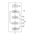
表示制御部44は、図3に示すように、メモリ50と、補正部52とを有する。
メモリ50は、外部から送られてくる表示データ信号を一時的に格納する。本実施形態では、図3に示すように、1つのメモリ50しか設けられていないが、例えば、左眼用画像を表示するための表示データ信号を一時的に格納するメモリと、右眼用画像を表示するための表示データ信号を一時的に格納するメモリとを設けても良い。また、メモリを設けなくても良い。
補正部52は、合成画像に含まれる複数の画像のうち、本来観察者が見るべき画像を表示する画素の階調データ(本実施形態では、階調値)を補正する。これにより、クロストークの発生を抑えることができる。クロストークとは、合成画像に含まれる複数の画像のうち、本来観察者が見るべき画像以外の画像が見えてしまう現象である。クロストークは、例えば、表示装置10における各層間での多重反射や視差バリア34の遮光層30からの光漏れ等によって生じる。
補正部52は、生成部54と、決定部56と、演算部58とを有する。
生成部54は、合成画像に含まれる複数の画像のうち、本来観察者が見るべき画像以外の画像を表示する画素の階調データに基づいて、クロストークの要因になる要因階調データを生成する。クロストークの要因になる画素は、例えば、視差バリアが有する遮光層と透光スリットとの位置関係等によって異なる。本実施形態では、遮光層30と、透光スリット32とが、表示装置10の表示画面の左右方向に交互に形成された視差バリア34が採用されているので、クロストークの要因になる画素は、本来観察者が見るべき画像を表示する画素に対して、表示装置10の表示画面の左右方向で両隣に位置する画素である。換言すれば、本実施形態では、クロストークの要因になる画素は、マトリクス状に形成された複数の画素のうち、本来観察者が見るべき画像を表示する画素に対して、行方向で両隣に位置する画素である。
例えば、図4に示す画素Lnにおいては、画素Lnの両隣に位置する画素Rn-1と画素Rnがクロストークの要因になる。画素Lnのクロストークを補正する際に用いる要因階調データI´Rnは、下式(3)によって求められる。
I´Rn=(IRn-1+IRn)/2・・・(3)
ここで、IRn-1は、画素Rn-1の階調データである。IRnは、画素Rnの階調データである。例えば、256階調の場合、IRn-1とIRnの範囲は、それぞれ、0~255になる。
I´Rn=(IRn-1+IRn)/2・・・(3)
ここで、IRn-1は、画素Rn-1の階調データである。IRnは、画素Rnの階調データである。例えば、256階調の場合、IRn-1とIRnの範囲は、それぞれ、0~255になる。
決定部56は、生成部54によって生成された要因階調データを用いて、補正量を決定する。補正量は、階調データを補正する際に用いられる。例えば、図4に示す画素Lnのクロストークを補正する際に用いる補正量DLnは、下式(4)によって求められる。
DLn=K×(IM-ILn-I´Rn-1)/(IM+1)・・・(4)
ここで、IMは階調データの最大値である。例えば、256階調の場合、IMは255になる。ILnは、画素Lnの階調データである。例えば、256階調の場合、ILnの範囲は、0~255になる。Kは、クロストークレベルC(後述する)に1加算したものである。
DLn=K×(IM-ILn-I´Rn-1)/(IM+1)・・・(4)
ここで、IMは階調データの最大値である。例えば、256階調の場合、IMは255になる。ILnは、画素Lnの階調データである。例えば、256階調の場合、ILnの範囲は、0~255になる。Kは、クロストークレベルC(後述する)に1加算したものである。
演算部58は、決定部56によって決定された補正量を用いて、画素の階調データを補正する。例えば、図4に示す画素Lnの補正後の階調データIoLnは、下式(5)によって求められる。
IoLn=ILn+DLn・・・(5)
IoLn=ILn+DLn・・・(5)
各画素が複数のサブ画素(例えば、赤色画素、緑色画素及び青色画素等)を有する場合、要因階調データ、補正量及び補正後の階調データは、サブ画素毎に生成される。
なお、生成部54は、観察者が本来見るべき画像を表示する画素であって、合成画像が表示される表示領域(図示せず)の端に位置する画素についての要因階調データを生成する際、観察者が本来見るべき画像以外の画像を表示する画素であって、本来存在しない画素の階調データを仮定し、当該仮定した階調データを用いて、要因階調データを生成する。本来存在しない画素の階調データを仮定する方法としては、例えば、観察者が本来見るべき画像以外の画像を表示する画素であって、実際に存在する画素の階調データを適当な数値(例えば、2)で除する方法等を採用することができる。実際に存在する画素が複数ある場合には、これらの画素の階調データの平均値を適当な数値で除する方法等を採用することができる。
上記の式(3)~(5)は、左眼用画像を表示する画素Lの階調データを補正する場合についてのものであったが、右眼用画像を表示する画素Rの階調データを補正する場合の式は、上記の式(3)~(5)において、RとLを変更するだけで良い。従って、右眼用画像を表示する画素Rの階調データを補正する場合については、詳細な説明を省略する。
上記(5)式が示す内容を明らかにするために、式(5)が如何にして導出されるかを説明する。
先ず、クロストーク率をFとすると、左眼に入ってくる画素の階調データは、下式(6)で表される。
IL+(F×IR)・・・(6)
ここで、ILは、左眼に入ってくる画素の階調データのうち、左眼用画像を表示する画素Lの階調データILに起因する部分を示す。F×IRは、左眼に入ってくる画素の階調データのうち、クロストークに起因する部分を示す。即ち、F×IRは、右眼用画像を表示する画素Rの階調データIRにクロストーク率Fを乗算したものである。Fの範囲は、0~1である。
IL+(F×IR)・・・(6)
ここで、ILは、左眼に入ってくる画素の階調データのうち、左眼用画像を表示する画素Lの階調データILに起因する部分を示す。F×IRは、左眼に入ってくる画素の階調データのうち、クロストークに起因する部分を示す。即ち、F×IRは、右眼用画像を表示する画素Rの階調データIRにクロストーク率Fを乗算したものである。Fの範囲は、0~1である。
Fは、例えば、視差バリア34において隣り合う2つの遮光層30,30の間隔、遮光層30の形状、遮光層30の材料、遮光層30の形成位置、遮光層30の幅、遮光層30の厚さ、遮光層30と画素R,Lとの位置関係等に起因して、表示装置10毎に異なる。Fは、表示装置10毎に測定して求めることができる。Fの測定方法としては、例えば、左眼用画像を表示する画素を黒表示し、且つ、右眼用画像を表示する画素を白表示した場合に左眼に入ってくる画素の輝度を測定すると共に、左眼用画像を表示する画素と右眼用画像を表示する画素の両方を黒表示した場合に左眼に入ってくる画素の輝度を測定し、これらの輝度の差から計算する方法等を採用することができる。
Fは、C/IMと表すこともできる。ここで、Cは、クロストークレベルである。例えば、256階調の場合、Cの範囲は、0~255である。FをC/IMとして表せば、式(6)は以下のようになる。
IL+(C/IM)×IR・・・(6´)
IL+(C/IM)×IR・・・(6´)
式(6´)で表される、左眼に入ってくる画素の階調データを補正するには、下式(7)のように補正する必要がある。これは、事前にクロストークの影響分を減算しておくことにより、クロストークの影響を受けた後の階調データが、本来表示したい階調データになるように補正するものである。
IL-(C/IM)×IR+(C/IM)×IR=IL・・・(7)
IL-(C/IM)×IR+(C/IM)×IR=IL・・・(7)
従って、補正後の階調データは、下式(8)のように表すことができる。
IL-(C/IM)×IR・・・(8)
IL-(C/IM)×IR・・・(8)
ここで、補正後の階調データが負になるのを防ぐために、階調を予めCだけ浮かす必要がある。換言すれば、階調データの範囲をC~IMに変更する必要がある。例えば、256階調の場合、階調データの範囲をC~255に変更する必要がある。ILをCだけ浮かせたものをIbとすると、Ibは下式(9)のように表すことができる。
Ib=IL×((IM-C)/IM)+C・・・(9)
Ib=IL×((IM-C)/IM)+C・・・(9)
従って、補正後の階調データIoは、(8)式のILに、(9)式のIbを代入して計算すると、下式(10)のようになる。
Io=Ib-(C/IM)×IR
=(IM×IL-C×IL-C×IR)/IM+C・・・(10)
Io=Ib-(C/IM)×IR
=(IM×IL-C×IL-C×IR)/IM+C・・・(10)
ここで、ハードウェアで計算する際に、回路が複雑になるのを回避するため、式(10)を近似すると、式(10)は以下のようになる。
Io+1=((IM+1)×(IL+1)-(C+1)×(IL+1)-(C+1)×(IR+1))/(IM+1)+(C+1)・・・(10´)
Io+1=((IM+1)×(IL+1)-(C+1)×(IL+1)-(C+1)×(IR+1))/(IM+1)+(C+1)・・・(10´)
式(10)の近似は、Io、IM、IL、IR及びCに1加算することで行われる。
式(10´)において、C+1をKとして計算すると、式(10´)は以下のようになる。
Io+1=IL+1+K×(IM-IL-IR-1)/(IM+1)・・・(11)
Io+1=IL+1+K×(IM-IL-IR-1)/(IM+1)・・・(11)
従って、(11)式からIoを求める式は、以下のようになる。
Io=IL+K×(IM-IL-IR-1)/(IM+1)・・・(12)
Io=IL+K×(IM-IL-IR-1)/(IM+1)・・・(12)
ここで、256階調の場合、IM+1は256になるので、式(12)は以下のように表すことができる。
Io=IL+K×(IM-IL-IR-1)>>8・・・(13)
Io=IL+K×(IM-IL-IR-1)>>8・・・(13)
式(13)において、>>8は、下位8ビットシフト(256での除算)を意味する。
演算部58によって演算される補正後の階調データは、式(12)又は式(13)で表される。決定部56によって決定される補正量は、式(12)又は式(13)の第2項で表される。生成部54によって生成される要因階調データは、式(12)又は式13の第2項に含まれるIRである。
上記の式(6)~(13)は、左眼用画像を表示する画素Lの階調データを補正する場合についてのものであったが、右眼用画像を表示する画素Rの階調データを補正する場合の式は、上記の式(6)~(13)において、RとLを変更するだけで良い。従って、右眼用画像を表示する画素Rの階調データを補正する場合については、詳細な説明を省略する。
上述のようにして各画素の階調データを補正すれば、最適なクロストーク補正をすることができる。その結果、表示品位の更なる向上を図ることが可能となる。
本実施形態においては、要因階調データが、本来観察者が見るべき画像を表示する画素の左右両隣に位置する画素の階調データを平均したものであるから、要因階調データを簡単に生成することができる。
[第1の実施形態の応用例1]
本応用例において、図4に示す画素Lnのクロストークを補正する際に用いる要因階調データI´Rnは、下式(14)によって求められる。
I´Rn=An-1×IRn-1+An×IRn・・・(14)
ここで、An-1は、画素Rn-1のクロストークへの寄与率を示す。Anは、画素Rnのクロストークへの寄与率を示す。An-1及びAnの範囲は、それぞれ、0~1である。
本応用例において、図4に示す画素Lnのクロストークを補正する際に用いる要因階調データI´Rnは、下式(14)によって求められる。
I´Rn=An-1×IRn-1+An×IRn・・・(14)
ここで、An-1は、画素Rn-1のクロストークへの寄与率を示す。Anは、画素Rnのクロストークへの寄与率を示す。An-1及びAnの範囲は、それぞれ、0~1である。
An-1及びAnは、それぞれ、例えば、視差バリア34において隣り合う2つの遮光層30,30の間隔、遮光層30の形状、遮光層30の形成位置、遮光層30の幅、遮光層30と画素R,Lとの位置関係等に起因して、表示装置毎に異なる。An-1及びAnは、それぞれ、表示装置毎に測定して求めることができる。測定方法としては、例えば、全ての画素(画素Ln、画素Rn及び画素Rn-1)を黒表示した場合に左眼に入ってくる画素の輝度と、測定対象となる画素を白表示した状態で、残りの画素を黒表示した場合に左眼に入ってくる画素の輝度とを測定し、これらの輝度の差から計算する方法等を採用することができる。
上記の式(14)は、左眼用画像を表示する画素Lの階調データを補正する場合についてのものであったが、右眼用画像を表示する画素Rの階調データを補正する場合の式は、上記の式(14)において、RとLを変更するだけで良い。従って、右眼用画像を表示する画素Rの階調データを補正する場合については、詳細な説明を省略する。
本応用例においては、観察者が本来見るべき画像を表示する画素の両隣に位置する画素のクロストークへの寄与率を用いて、要因階調データを求めるようになっている。これにより、観察者が本来見るべき画像を表示する画素の両隣に位置する画素のクロストークへの寄与率が同じであると仮定して要因階調データを求める場合(第1の実施形態の場合)に比して、より適正な要因階調データを得ることができる。その結果、クロストーク補正の精度を更に向上させることが可能となる。
[第1の実施形態の応用例2]
本応用例においては、図5に示すように、バリア部14の代わりに、分離部としてのレンチキュラーレンズ60が配置されている。レンチキュラーレンズ60は、画素Rの列と画素Lの列とが交互に並ぶ方向に複数のシリンドリカルレンズ62が配列されたものである。レンチキュラーレンズ60は、各シリンドリカルレンズ62が画素R,Lの列に対応するようにして、対向基板20側に配置される偏光板38bに貼り付けられている。なお、本応用例において、対向基板20側に配置される偏光板38bは、対向基板20に貼り付けられている。
本応用例においては、図5に示すように、バリア部14の代わりに、分離部としてのレンチキュラーレンズ60が配置されている。レンチキュラーレンズ60は、画素Rの列と画素Lの列とが交互に並ぶ方向に複数のシリンドリカルレンズ62が配列されたものである。レンチキュラーレンズ60は、各シリンドリカルレンズ62が画素R,Lの列に対応するようにして、対向基板20側に配置される偏光板38bに貼り付けられている。なお、本応用例において、対向基板20側に配置される偏光板38bは、対向基板20に貼り付けられている。
[第1の実施形態の応用例3]
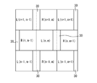
本応用例においては、図6に示すように、画素Rと画素Lが、表示パネル12の左右方向だけでなく、表示パネル12の上下方向においても、隣に位置している。また、遮光層30は、表示パネル12の上下方向に1画素分の隙間を空けるように形成されている。
本応用例においては、図6に示すように、画素Rと画素Lが、表示パネル12の左右方向だけでなく、表示パネル12の上下方向においても、隣に位置している。また、遮光層30は、表示パネル12の上下方向に1画素分の隙間を空けるように形成されている。
このようにして、画素R,L及び遮光層30を配置すれば、遮光層30がストライプ状に形成されている場合に比して、遮光層30を見え難くすることができる。
本応用例においては、表示パネル12の左右方向で両隣に位置する画素だけでなく、表示パネル12の上下方向で両隣に位置する画素も、クロストークの要因になる。例えば、図6に示す画素L(n,m)においては、表示パネル12の左右方向で両隣に位置する画素R(n,m-1)及び画素R(n,m+1)と、表示パネル12の上下方向で両隣に位置する画素R(n+1,m)及び画素R(n-1,m)とが、クロストークの要因になる。画素L(n,m)のクロストークを補正する際に用いる要因階調データI´Rは、下式(15)によって求められる。
I´R=(IR(n,m-1)+IR(n,m+1)+IR(n+1,m)+IR(n-1,m))/4・・・(15)
ここで、IR(n,m-1)は、画素R(n,m-1)の階調データである。IR(n,m+1)は、画素R(n,m+1)の階調データである。IR(n+1,m)は、画素R(n+1,m)の階調データである。IR(n-1,m)は、画素R(n-1,m)の階調データである。
I´R=(IR(n,m-1)+IR(n,m+1)+IR(n+1,m)+IR(n-1,m))/4・・・(15)
ここで、IR(n,m-1)は、画素R(n,m-1)の階調データである。IR(n,m+1)は、画素R(n,m+1)の階調データである。IR(n+1,m)は、画素R(n+1,m)の階調データである。IR(n-1,m)は、画素R(n-1,m)の階調データである。
なお、画素L(n,m)のクロストークを補正する際に用いる要因階調データI´Rは、下式(16)によって求めるようにしても良い。
I´R=A(n,m-1)×IR(n,m-1)+A(n,m+1)×IR(n,m+1)+A(n+1,m)×IR(n+1,m)+A(n-1,m)×IR(n-1,m)・・・(16)
ここで、A(n,m-1)は、画素R(n,m-1)のクロストークへの寄与率である。A(n,m+1)は、画素R(n,m+1)のクロストークへの寄与率である。A(n+1,m)は、画素R(n+1,m)のクロストークへの寄与率である。A(n-1,m)は、画素R(n-1,m)のクロストークへの寄与率である。A(n,m-1)、A(n,m+1)、A(n+1,m)及びA(n-1,m)の範囲は、それぞれ、0~1である。
I´R=A(n,m-1)×IR(n,m-1)+A(n,m+1)×IR(n,m+1)+A(n+1,m)×IR(n+1,m)+A(n-1,m)×IR(n-1,m)・・・(16)
ここで、A(n,m-1)は、画素R(n,m-1)のクロストークへの寄与率である。A(n,m+1)は、画素R(n,m+1)のクロストークへの寄与率である。A(n+1,m)は、画素R(n+1,m)のクロストークへの寄与率である。A(n-1,m)は、画素R(n-1,m)のクロストークへの寄与率である。A(n,m-1)、A(n,m+1)、A(n+1,m)及びA(n-1,m)の範囲は、それぞれ、0~1である。
A(n,m-1)、A(n,m+1)、A(n+1,m)及びA(n-1,m)は、それぞれ、例えば、隣り合う2つの遮光層30,30の間隔、遮光層30の形状、遮光層30の形成位置、遮光層30の幅、遮光層30と画素R,Lとの位置関係等に起因して、表示装置毎に異なる。A(n,m-1)、A(n,m+1)、A(n+1,m)及びA(n-1,m)は、それぞれ、表示装置毎に測定して求めることができる。測定方法としては、例えば、全ての画素(画素L(n,m)、画素R(n,m-1)、画素R(n,m+1)、画素R(n+1,m)及び画素R(n-1,m))を黒表示した場合に左眼に入ってくる画素の輝度と、測定対象となる画素を白表示した状態で、残りの画素を黒表示した場合に左眼に入ってくる画素の輝度とを測定し、これらの輝度の差から計算する方法等を採用することができる。
上記の式(15)及び(16)は、左眼用画像を表示する画素Lの階調データを補正する場合についてのものであったが、右眼用画像を表示する画素Rの階調データを補正する場合の式は、上記の式(15)及び(16)において、RとLを変更するだけで良い。従って、右眼用画像を表示する画素Rの階調データを補正する場合については、詳細な説明を省略する。
[第1の実施形態の応用例4]
本応用例においては、図7に示すように、バリア部14の代わりに、液晶パネル64を備える。液晶パネル64は、一対の基板66,66間に液晶層68が封入された構造を有する。一対の基板66,66間に電圧を印加すると、液晶層68の屈折率が部分的に変化する。その結果、分離部としての液晶レンズが実現される。
本応用例においては、図7に示すように、バリア部14の代わりに、液晶パネル64を備える。液晶パネル64は、一対の基板66,66間に液晶層68が封入された構造を有する。一対の基板66,66間に電圧を印加すると、液晶層68の屈折率が部分的に変化する。その結果、分離部としての液晶レンズが実現される。
[第1の実施形態の応用例5]
本応用例においては、図8に示すように、バリア部14の代わりに、部分位相差板70が配置されている。即ち、本応用例は、偏光メガネ方式の立体表示装置に関するものである。
本応用例においては、図8に示すように、バリア部14の代わりに、部分位相差板70が配置されている。即ち、本応用例は、偏光メガネ方式の立体表示装置に関するものである。
部分位相差板70は、位相差部72と非位相差部74とが交互に並んだものである。位相差部72は、1/2波長板であり、入射光(直線偏光)の偏光方向を90度回転させる。
本応用例では、左眼用画像を表示する画素Lが位相差部72を通して観察者に見え、右眼用画像を表示する画素Rが非位相差部74を通して観察者に見える。観察者は、偏光メガネ76を用いることにより、左眼用画像を左眼だけで見ることができ、右眼用画像を右眼だけで見ることができる。
[第1の実施形態の応用例6]
本応用例では、図9に示すように、補正部52が変更部78を備える。変更部78は、例えば、メモリ50と生成部54との間に配置される。変更部78は、階調データが、階調値ではなく、例えば、電圧値や輝度値である場合に、256階調(8ビット)を表すために、これら電圧値や輝度値を所定ビット(例えば、10ビットや16ビット)のデータとして取り扱えるようにするものである。補正部52は、変更部78によって変更されたデータを用いて、階調データを補正する。
本応用例では、図9に示すように、補正部52が変更部78を備える。変更部78は、例えば、メモリ50と生成部54との間に配置される。変更部78は、階調データが、階調値ではなく、例えば、電圧値や輝度値である場合に、256階調(8ビット)を表すために、これら電圧値や輝度値を所定ビット(例えば、10ビットや16ビット)のデータとして取り扱えるようにするものである。補正部52は、変更部78によって変更されたデータを用いて、階調データを補正する。
本応用例では、階調データが階調値でなくても、階調データの補正が容易にできる。
[第1の実施形態の応用例7]
本応用例では、図10に示すように、生成部54がルックアップテーブル80を有する。ルックアップテーブル80は、観察者が本来見るべき画像以外の画像を表示する画素の階調データと、要因階調データとの関係を示す。ルックアップテーブル80には、例えば、観察者が本来見るべき画像以外の画像を表示する画素であって、観察者が本来見るべき画像を表示する画素の両隣に位置する画素の階調データの差分値と、当該差分値に対応する要因階調データとが記憶される。
本応用例では、図10に示すように、生成部54がルックアップテーブル80を有する。ルックアップテーブル80は、観察者が本来見るべき画像以外の画像を表示する画素の階調データと、要因階調データとの関係を示す。ルックアップテーブル80には、例えば、観察者が本来見るべき画像以外の画像を表示する画素であって、観察者が本来見るべき画像を表示する画素の両隣に位置する画素の階調データの差分値と、当該差分値に対応する要因階調データとが記憶される。
[第2の実施形態]
続いて、本発明の第2の実施形態としての表示装置について説明する。なお、以下の記載において、第1の実施形態と同様な構造とされた部材及び部位については、図中に、第1の実施形態と同一の符号を付すことにより、それらの詳細な説明を省略する。
続いて、本発明の第2の実施形態としての表示装置について説明する。なお、以下の記載において、第1の実施形態と同様な構造とされた部材及び部位については、図中に、第1の実施形態と同一の符号を付すことにより、それらの詳細な説明を省略する。
本実施形態の表示装置は、第1の実施形態の表示装置10に比して、視点数が異なっている。第1の実施形態の表示装置10は1視点の立体表示装置であったが、本実施形態の表示装置は、図11に示すように、4視点の立体表示装置である。
位置(1)の観察者の左眼においては、画素P(n±*)5によって表示される画像が見える。位置(1)の観察者の右眼及び位置(2)の観察者の左眼においては、画素P(n±*)4によって表示される画像が見える。位置(2)の観察者の右眼及び位置(3)の観察者の左眼においては、画素P(n±*)3によって表示される画像が見える。位置(3)の観察者の右眼及び位置(4)の観察者の左眼においては、画素P(n±*)2によって表示される画像が見える。位置(4)の観察者の右眼においては、画素P(n±*)1によって表示される画像が見える。なお、各画素の表記において、*は、0又は任意の自然数を示す。
ここで、特定の方向に表示される画像を観察する観察者にとっては、当該特定の方向とは異なる方向に表示される画像が、クロストークとして認識される。例えば、図11に示す位置(1)の観察者の左眼において、位置(1)での左眼用画像以外の画像が見えた場合、当該画像がクロストークとして認識される。また、図11に示す位置(1)の観察者の右眼において、位置(1)での右眼用画像以外の画像が見えた場合、当該画像がクロストークとして認識される。
本実施形態においては、ある画素のクロストークの要因になる画素は、当該画素の左側に位置する四つの画素と、当該画素の右側に位置する四つの画素である。例えば、図11に示す画素P(n)5のクロストークの要因になる画素は、画素P(n)5の左側に位置する4つの画素P(n)1、P(n)2、P(n)3、P(n)4と、画素P(n)5の右側に位置する4つの画素P(n+1)1、P(n+1)2、P(n+1)3、P(n+1)4である。画素P(n)5のクロストークを補正する際に用いる要因階調データI´n5は、下式(17)によって求められる。
I´(n)5=A(n)1×I(n)1+A(n)2×I(n)2+A(n)3×I(n)3+A(n)4×I(n)4+A(n+1)1×I(n+1)1+A(n+1)2×I(n+1)2+A(n+1)3×I(n+1)3+A(n+1)4×I(n+1)4・・・(17)
ここで、A(n)1は、画素P(n)1のクロストークへの寄与率を示す。A(n)2は、画素P(n)2のクロストークへの寄与率を示す。A(n)3は、画素P(n)3のクロストークへの寄与率を示す。A(n)4は、画素P(n)4のクロストークへの寄与率を示す。A(n+1)1は、画素P(n+1)1のクロストークへの寄与率を示す。A(n+1)2は、画素P(n+1)2のクロストークへの寄与率を示す。A(n+1)3は、画素P(n+1)3のクロストークへの寄与率を示す。A(n+1)4は、画素P(n+1)4のクロストークへの寄与率を示す。
I´(n)5=A(n)1×I(n)1+A(n)2×I(n)2+A(n)3×I(n)3+A(n)4×I(n)4+A(n+1)1×I(n+1)1+A(n+1)2×I(n+1)2+A(n+1)3×I(n+1)3+A(n+1)4×I(n+1)4・・・(17)
ここで、A(n)1は、画素P(n)1のクロストークへの寄与率を示す。A(n)2は、画素P(n)2のクロストークへの寄与率を示す。A(n)3は、画素P(n)3のクロストークへの寄与率を示す。A(n)4は、画素P(n)4のクロストークへの寄与率を示す。A(n+1)1は、画素P(n+1)1のクロストークへの寄与率を示す。A(n+1)2は、画素P(n+1)2のクロストークへの寄与率を示す。A(n+1)3は、画素P(n+1)3のクロストークへの寄与率を示す。A(n+1)4は、画素P(n+1)4のクロストークへの寄与率を示す。
A(n)1、A(n)2、A(n)3、A(n)4、A(n+1)1、A(n+1)2、A(n+1)3及びA(n+1)4は、それぞれ、例えば、隣り合う2つの遮光層30,30の間隔、遮光層30の形状、遮光層30の形成位置、遮光層30の幅、遮光層30と画素との位置関係等に起因して、表示装置毎に異なるものである。A(n)1、A(n)2、A(n)3、A(n)4、A(n+1)1、A(n+1)2、A(n+1)3及びA(n+1)4は、それぞれ、表示装置毎に測定して求めることができる。測定方法としては、例えば、全ての画素(画素P(n)1、P(n)2、P(n)3、P(n)4、P(n)5、P(n+1)1、P(n+1)2、P(n+1)3、P(n+1)4)を黒表示した場合に左眼に入ってくる画素の輝度と、測定対象となる画素を白表示した状態で、残りの画素を黒表示した場合に左眼に入ってくる画素の輝度とを測定し、これらの輝度の差から計算する方法等を採用することができる。
上記の式(17)は、画素P(n)5の階調データを補正する場合についてのものであったが、他の画素についても、画素P(n)5の場合と同じようにして、階調データを補正することができる。従って、他の画素の階調データを補正する場合については、詳細な説明を省略する。
以上、本発明の実施形態について、詳述してきたが、これらはあくまでも例示であって、本発明は、上述の実施形態によって、何等、限定されない。
例えば、前記第1及び第2の実施形態において、バリア部14の代わりに、スイッチ液晶パネルを採用しても良い。スイッチ液晶パネルは、一対の基板間に液晶層が封入された構造を有する。一対の基板間に電圧を印加することによって、光を透過させる部分(透光スリット)と、光を遮断する部分(遮光層)とを有する視差バリア(分離部)が形成される。スイッチ液晶パネルを採用することにより、スイッチ液晶パネルに視差バリアを形成しない場合には、平面画像を観察者に見せることができる。また、スイッチ液晶パネルを採用すると、例えば、表示装置を縦(横)向きから横(縦)向きに変化させた場合であっても、換言すれば、表示装置が縦向きと横向きの何れであっても、3Dディスプレイや、マルチビューディスプレイを実現することができる。
前記第1及び第2の実施形態において、表示パネルは、プラズマディスプレイパネル、有機EL(Electro Luminescence)パネル、無機ELパネル等であっても良い。
前記第1及び第2の実施形態において、クロストークの要因になる画素として、本来観察者が見るべき画像を表示する画素に対して、斜め方向で隣に位置する画素を追加しても良い。
本発明は、共通の表示画面を用いて複数の方向に異なる画像を表示する表示装置に対しても、勿論、適用可能である。
Claims (11)
- 互いに異なる複数の画像をそれぞれ分割し、これらの分割画像を所定の順番に並べることで形成された合成画像を表示する表示部と、
前記合成画像に含まれる前記複数の画像を分離する分離部と、
前記合成画像に含まれる前記複数の画像のうち、本来観察者が見るべき画像を表示する画素の階調データを補正する補正部とを備え、
前記補正部は、
前記合成画像に含まれる前記複数の画像のうち、本来観察者が見るべき画像以外の画像を表示する画素の階調データに基づいて、クロストークの要因になる要因階調データを生成する生成部と、
前記要因階調データを利用して、前記階調データを補正する際に用いる補正量を決定する決定部とを備える、表示装置。 - 観察者が本来見るべき画像を表示する画素の階調データをIXとし、
前記要因階調データをIYとし、
観察者が本来見るべき画像を表示する画素の階調データの最大値をIMとし、
クロストークレベルをCとし、
前記補正部によって補正された画素の階調データをIOとした場合において、
前記決定部が、下式(1)によって、前記補正量Dを決定し、
D=(C+1)×(IM-IX-IY-1)/(IM+1)・・・(1)
前記補正部が、下式(2)によって、観察者が本来見るべき画像を表示する画素の階調データを補正する、請求項1に記載の表示装置。
IO=IX+D・・・(2) - 前記生成部は、前記合成画像に含まれる前記複数の画像のうち、本来観察者が見るべき画像以外の画像を表示する画素の階調データを平均することで、前記要因階調データを生成する、請求項1又は2に記載の表示装置。
- 前記生成部は、前記合成画像に含まれる前記複数の画像のうち、本来観察者が見るべき画像以外の画像を表示する画素の階調データ毎に、当該画素の該クロストークへの寄与率を乗算し、これらを合計することで、前記要因階調データを生成する、請求項1又は2に記載の表示装置。
- 前記生成部は、観察者が本来見るべき画像以外の画像を表示する画素の階調データと、前記要因階調データとの関係を示すルックアップテーブルを有しており、
前記生成部は、観察者が本来見るべき画像以外の画像を表示する画素の階調データと、前記ルックアップテーブルとを用いて、前記要因階調データを生成する、請求項1又は2に記載の表示装置。 - 前記分離部が、前記合成画像に含まれる前記複数の画像を互いに異なる方向から見られるように分離する視差バリアである、請求項1~5の何れか1項に記載の表示装置。
- 前記分離部が、前記合成画像に含まれる前記複数の画像を互いに異なる方向から見られるように分離するレンチキュラーレンズである、請求項1~5の何れか1項に記載の表示装置。
- 前記分離部が、前記合成画像に含まれる前記複数の画像を互いに異なる方向から見られるように分離する液晶レンズである、請求項1~5の何れか1項に記載の表示装置。
- 前記分離部が、前記合成画像に含まれる前記複数の画像を互いに異なる方向から見られるように分離する部分位相差板である、請求項1~5の何れか1項に記載の表示装置。
- 前記生成部は、観察者が本来見るべき画像を表示する画素であって、前記合成画像が表示される表示領域の端に位置する画素についての前記要因階調データを生成する際に、観察者が本来見るべき画像以外の画像を表示する画素であって、本来存在しない画素の階調データを仮定し、当該仮定した階調データを用いて、該要因階調データを生成する、請求項1~9の何れか1項に記載の表示装置。
- 前記階調データを所定ビットのデータに変換する変換部を更に備え、
前記変換部によって変換されたデータを用いて、前記補正部が前記階調データを補正する、請求項1~10の何れか1項に記載の表示装置。
Applications Claiming Priority (2)
| Application Number | Priority Date | Filing Date | Title |
|---|---|---|---|
| JP2011-040267 | 2011-02-25 | ||
| JP2011040267 | 2011-02-25 |
Publications (1)
| Publication Number | Publication Date |
|---|---|
| WO2012115160A1 true WO2012115160A1 (ja) | 2012-08-30 |
Family
ID=46720935
Family Applications (1)
| Application Number | Title | Priority Date | Filing Date |
|---|---|---|---|
| PCT/JP2012/054302 Ceased WO2012115160A1 (ja) | 2011-02-25 | 2012-02-22 | 表示装置 |
Country Status (1)
| Country | Link |
|---|---|
| WO (1) | WO2012115160A1 (ja) |
Cited By (1)
| Publication number | Priority date | Publication date | Assignee | Title |
|---|---|---|---|---|
| WO2013089153A1 (ja) * | 2011-12-15 | 2013-06-20 | シャープ株式会社 | 表示装置 |
Citations (4)
| Publication number | Priority date | Publication date | Assignee | Title |
|---|---|---|---|---|
| JP2008009039A (ja) * | 2006-06-28 | 2008-01-17 | Epson Imaging Devices Corp | 電気光学装置及び電子機器 |
| JP2008262157A (ja) * | 2007-03-20 | 2008-10-30 | Epson Imaging Devices Corp | 2画面表示装置 |
| JP2008299040A (ja) * | 2007-05-31 | 2008-12-11 | Epson Imaging Devices Corp | 画像表示装置 |
| JP2009145640A (ja) * | 2007-12-14 | 2009-07-02 | Epson Imaging Devices Corp | 表示装置 |
-
2012
- 2012-02-22 WO PCT/JP2012/054302 patent/WO2012115160A1/ja not_active Ceased
Patent Citations (4)
| Publication number | Priority date | Publication date | Assignee | Title |
|---|---|---|---|---|
| JP2008009039A (ja) * | 2006-06-28 | 2008-01-17 | Epson Imaging Devices Corp | 電気光学装置及び電子機器 |
| JP2008262157A (ja) * | 2007-03-20 | 2008-10-30 | Epson Imaging Devices Corp | 2画面表示装置 |
| JP2008299040A (ja) * | 2007-05-31 | 2008-12-11 | Epson Imaging Devices Corp | 画像表示装置 |
| JP2009145640A (ja) * | 2007-12-14 | 2009-07-02 | Epson Imaging Devices Corp | 表示装置 |
Cited By (2)
| Publication number | Priority date | Publication date | Assignee | Title |
|---|---|---|---|---|
| WO2013089153A1 (ja) * | 2011-12-15 | 2013-06-20 | シャープ株式会社 | 表示装置 |
| US9330615B2 (en) | 2011-12-15 | 2016-05-03 | Sharp Kabushiki Kaisha | Display device with crosstalk level correction |
Similar Documents
| Publication | Publication Date | Title |
|---|---|---|
| JP5550165B2 (ja) | 電子映像機器 | |
| US8760505B2 (en) | Image display device for displaying two-dimensional plane image and three-dimensional stereoscopic image | |
| CN102193239B (zh) | 立体图像显示器及其驱动方法 | |
| US8633974B2 (en) | Image display device | |
| KR101212170B1 (ko) | 패턴드 리타더를 이용한 입체 영상 표시 장치 및 그 구동 방법 | |
| US8836775B2 (en) | Stereoscopic image display device and driving method thereof | |
| US20120194509A1 (en) | Method and apparatus for displaying partial 3d image in 2d image display area | |
| US8933924B2 (en) | Display device and electronic unit | |
| US20130208020A1 (en) | Display apparatus and method of displaying three-dimensional image using the same | |
| WO2013089067A1 (ja) | 表示装置 | |
| WO2012127945A1 (ja) | 表示装置 | |
| US20140015864A1 (en) | Display apparatus and a method of displaying a three-dimensional image using the same | |
| US9330615B2 (en) | Display device with crosstalk level correction | |
| WO2013089068A1 (ja) | 表示装置 | |
| WO2012115161A1 (ja) | 表示装置 | |
| KR101735396B1 (ko) | 패턴드 리타더를 이용한 입체 영상 표시 장치 및 그 구동 방법 | |
| WO2012115160A1 (ja) | 表示装置 | |
| KR101752006B1 (ko) | 입체영상 표시장치 및 그 구동방법 | |
| KR101705902B1 (ko) | 입체영상 표시장치 및 그 구동방법 | |
| US9626935B2 (en) | Stereoscopic image display device and method for driving the same | |
| KR20130037326A (ko) | 3d 화질개선방법과 이를 이용한 입체영상 표시장치 | |
| JP2007003941A (ja) | 立体表示装置 | |
| CN118778280A (zh) | 立体图像显示装置 | |
| KR20120139221A (ko) | 영상표시장치 | |
| KR20120050128A (ko) | 영상표시장치 |
Legal Events
| Date | Code | Title | Description |
|---|---|---|---|
| 121 | Ep: the epo has been informed by wipo that ep was designated in this application |
Ref document number: 12749800 Country of ref document: EP Kind code of ref document: A1 |
|
| NENP | Non-entry into the national phase |
Ref country code: DE |
|
| 122 | Ep: pct application non-entry in european phase |
Ref document number: 12749800 Country of ref document: EP Kind code of ref document: A1 |
|
| NENP | Non-entry into the national phase |
Ref country code: JP |