WO2012114924A1 - 空間光変調装置および空間光変調方法 - Google Patents
空間光変調装置および空間光変調方法 Download PDFInfo
- Publication number
- WO2012114924A1 WO2012114924A1 PCT/JP2012/053303 JP2012053303W WO2012114924A1 WO 2012114924 A1 WO2012114924 A1 WO 2012114924A1 JP 2012053303 W JP2012053303 W JP 2012053303W WO 2012114924 A1 WO2012114924 A1 WO 2012114924A1
- Authority
- WO
- WIPO (PCT)
- Prior art keywords
- temperature
- spatial light
- coefficient value
- pattern
- light modulation
- Prior art date
- Legal status (The legal status is an assumption and is not a legal conclusion. Google has not performed a legal analysis and makes no representation as to the accuracy of the status listed.)
- Ceased
Links
Images















Classifications
-
- G—PHYSICS
- G02—OPTICS
- G02F—OPTICAL DEVICES OR ARRANGEMENTS FOR THE CONTROL OF LIGHT BY MODIFICATION OF THE OPTICAL PROPERTIES OF THE MEDIA OF THE ELEMENTS INVOLVED THEREIN; NON-LINEAR OPTICS; FREQUENCY-CHANGING OF LIGHT; OPTICAL LOGIC ELEMENTS; OPTICAL ANALOGUE/DIGITAL CONVERTERS
- G02F1/00—Devices or arrangements for the control of the intensity, colour, phase, polarisation or direction of light arriving from an independent light source, e.g. switching, gating or modulating; Non-linear optics
- G02F1/01—Devices or arrangements for the control of the intensity, colour, phase, polarisation or direction of light arriving from an independent light source, e.g. switching, gating or modulating; Non-linear optics for the control of the intensity, phase, polarisation or colour
- G02F1/13—Devices or arrangements for the control of the intensity, colour, phase, polarisation or direction of light arriving from an independent light source, e.g. switching, gating or modulating; Non-linear optics for the control of the intensity, phase, polarisation or colour based on liquid crystals, e.g. single liquid crystal display cells
- G02F1/133—Constructional arrangements; Operation of liquid crystal cells; Circuit arrangements
-
- G—PHYSICS
- G02—OPTICS
- G02F—OPTICAL DEVICES OR ARRANGEMENTS FOR THE CONTROL OF LIGHT BY MODIFICATION OF THE OPTICAL PROPERTIES OF THE MEDIA OF THE ELEMENTS INVOLVED THEREIN; NON-LINEAR OPTICS; FREQUENCY-CHANGING OF LIGHT; OPTICAL LOGIC ELEMENTS; OPTICAL ANALOGUE/DIGITAL CONVERTERS
- G02F1/00—Devices or arrangements for the control of the intensity, colour, phase, polarisation or direction of light arriving from an independent light source, e.g. switching, gating or modulating; Non-linear optics
- G02F1/01—Devices or arrangements for the control of the intensity, colour, phase, polarisation or direction of light arriving from an independent light source, e.g. switching, gating or modulating; Non-linear optics for the control of the intensity, phase, polarisation or colour
- G02F1/13—Devices or arrangements for the control of the intensity, colour, phase, polarisation or direction of light arriving from an independent light source, e.g. switching, gating or modulating; Non-linear optics for the control of the intensity, phase, polarisation or colour based on liquid crystals, e.g. single liquid crystal display cells
- G02F1/133—Constructional arrangements; Operation of liquid crystal cells; Circuit arrangements
- G02F1/13306—Circuit arrangements or driving methods for the control of single liquid crystal cells
-
- G—PHYSICS
- G02—OPTICS
- G02B—OPTICAL ELEMENTS, SYSTEMS OR APPARATUS
- G02B26/00—Optical devices or arrangements for the control of light using movable or deformable optical elements
-
- G—PHYSICS
- G02—OPTICS
- G02B—OPTICAL ELEMENTS, SYSTEMS OR APPARATUS
- G02B26/00—Optical devices or arrangements for the control of light using movable or deformable optical elements
- G02B26/06—Optical devices or arrangements for the control of light using movable or deformable optical elements for controlling the phase of light
-
- G—PHYSICS
- G02—OPTICS
- G02F—OPTICAL DEVICES OR ARRANGEMENTS FOR THE CONTROL OF LIGHT BY MODIFICATION OF THE OPTICAL PROPERTIES OF THE MEDIA OF THE ELEMENTS INVOLVED THEREIN; NON-LINEAR OPTICS; FREQUENCY-CHANGING OF LIGHT; OPTICAL LOGIC ELEMENTS; OPTICAL ANALOGUE/DIGITAL CONVERTERS
- G02F1/00—Devices or arrangements for the control of the intensity, colour, phase, polarisation or direction of light arriving from an independent light source, e.g. switching, gating or modulating; Non-linear optics
- G02F1/01—Devices or arrangements for the control of the intensity, colour, phase, polarisation or direction of light arriving from an independent light source, e.g. switching, gating or modulating; Non-linear optics for the control of the intensity, phase, polarisation or colour
- G02F1/13—Devices or arrangements for the control of the intensity, colour, phase, polarisation or direction of light arriving from an independent light source, e.g. switching, gating or modulating; Non-linear optics for the control of the intensity, phase, polarisation or colour based on liquid crystals, e.g. single liquid crystal display cells
- G02F1/133—Constructional arrangements; Operation of liquid crystal cells; Circuit arrangements
- G02F1/136—Liquid crystal cells structurally associated with a semi-conducting layer or substrate, e.g. cells forming part of an integrated circuit
-
- G—PHYSICS
- G03—PHOTOGRAPHY; CINEMATOGRAPHY; ANALOGOUS TECHNIQUES USING WAVES OTHER THAN OPTICAL WAVES; ELECTROGRAPHY; HOLOGRAPHY
- G03H—HOLOGRAPHIC PROCESSES OR APPARATUS
- G03H1/00—Holographic processes or apparatus using light, infrared or ultraviolet waves for obtaining holograms or for obtaining an image from them; Details peculiar thereto
- G03H1/04—Processes or apparatus for producing holograms
- G03H1/08—Synthesising holograms, i.e. holograms synthesized from objects or objects from holograms
- G03H1/0808—Methods of numerical synthesis, e.g. coherent ray tracing [CRT], diffraction specific
-
- G—PHYSICS
- G03—PHOTOGRAPHY; CINEMATOGRAPHY; ANALOGOUS TECHNIQUES USING WAVES OTHER THAN OPTICAL WAVES; ELECTROGRAPHY; HOLOGRAPHY
- G03H—HOLOGRAPHIC PROCESSES OR APPARATUS
- G03H1/00—Holographic processes or apparatus using light, infrared or ultraviolet waves for obtaining holograms or for obtaining an image from them; Details peculiar thereto
- G03H1/22—Processes or apparatus for obtaining an optical image from holograms
- G03H1/2294—Addressing the hologram to an active spatial light modulator
-
- G—PHYSICS
- G09—EDUCATION; CRYPTOGRAPHY; DISPLAY; ADVERTISING; SEALS
- G09G—ARRANGEMENTS OR CIRCUITS FOR CONTROL OF INDICATING DEVICES USING STATIC MEANS TO PRESENT VARIABLE INFORMATION
- G09G3/00—Control arrangements or circuits, of interest only in connection with visual indicators other than cathode-ray tubes
- G09G3/20—Control arrangements or circuits, of interest only in connection with visual indicators other than cathode-ray tubes for presentation of an assembly of a number of characters, e.g. a page, by composing the assembly by combination of individual elements arranged in a matrix no fixed position being assigned to or needed to be assigned to the individual characters or partial characters
- G09G3/34—Control arrangements or circuits, of interest only in connection with visual indicators other than cathode-ray tubes for presentation of an assembly of a number of characters, e.g. a page, by composing the assembly by combination of individual elements arranged in a matrix no fixed position being assigned to or needed to be assigned to the individual characters or partial characters by control of light from an independent source
- G09G3/36—Control arrangements or circuits, of interest only in connection with visual indicators other than cathode-ray tubes for presentation of an assembly of a number of characters, e.g. a page, by composing the assembly by combination of individual elements arranged in a matrix no fixed position being assigned to or needed to be assigned to the individual characters or partial characters by control of light from an independent source using liquid crystals
-
- G—PHYSICS
- G02—OPTICS
- G02F—OPTICAL DEVICES OR ARRANGEMENTS FOR THE CONTROL OF LIGHT BY MODIFICATION OF THE OPTICAL PROPERTIES OF THE MEDIA OF THE ELEMENTS INVOLVED THEREIN; NON-LINEAR OPTICS; FREQUENCY-CHANGING OF LIGHT; OPTICAL LOGIC ELEMENTS; OPTICAL ANALOGUE/DIGITAL CONVERTERS
- G02F2203/00—Function characteristic
- G02F2203/12—Function characteristic spatial light modulator
-
- G—PHYSICS
- G02—OPTICS
- G02F—OPTICAL DEVICES OR ARRANGEMENTS FOR THE CONTROL OF LIGHT BY MODIFICATION OF THE OPTICAL PROPERTIES OF THE MEDIA OF THE ELEMENTS INVOLVED THEREIN; NON-LINEAR OPTICS; FREQUENCY-CHANGING OF LIGHT; OPTICAL LOGIC ELEMENTS; OPTICAL ANALOGUE/DIGITAL CONVERTERS
- G02F2203/00—Function characteristic
- G02F2203/21—Thermal instability, i.e. DC drift, of an optical modulator; Arrangements or methods for the reduction thereof
-
- G—PHYSICS
- G02—OPTICS
- G02F—OPTICAL DEVICES OR ARRANGEMENTS FOR THE CONTROL OF LIGHT BY MODIFICATION OF THE OPTICAL PROPERTIES OF THE MEDIA OF THE ELEMENTS INVOLVED THEREIN; NON-LINEAR OPTICS; FREQUENCY-CHANGING OF LIGHT; OPTICAL LOGIC ELEMENTS; OPTICAL ANALOGUE/DIGITAL CONVERTERS
- G02F2203/00—Function characteristic
- G02F2203/50—Phase-only modulation
-
- G—PHYSICS
- G02—OPTICS
- G02F—OPTICAL DEVICES OR ARRANGEMENTS FOR THE CONTROL OF LIGHT BY MODIFICATION OF THE OPTICAL PROPERTIES OF THE MEDIA OF THE ELEMENTS INVOLVED THEREIN; NON-LINEAR OPTICS; FREQUENCY-CHANGING OF LIGHT; OPTICAL LOGIC ELEMENTS; OPTICAL ANALOGUE/DIGITAL CONVERTERS
- G02F2203/00—Function characteristic
- G02F2203/60—Temperature independent
-
- G—PHYSICS
- G03—PHOTOGRAPHY; CINEMATOGRAPHY; ANALOGOUS TECHNIQUES USING WAVES OTHER THAN OPTICAL WAVES; ELECTROGRAPHY; HOLOGRAPHY
- G03H—HOLOGRAPHIC PROCESSES OR APPARATUS
- G03H1/00—Holographic processes or apparatus using light, infrared or ultraviolet waves for obtaining holograms or for obtaining an image from them; Details peculiar thereto
- G03H1/02—Details of features involved during the holographic process; Replication of holograms without interference recording
- G03H2001/0208—Individual components other than the hologram
- G03H2001/0224—Active addressable light modulator, i.e. Spatial Light Modulator [SLM]
-
- G—PHYSICS
- G03—PHOTOGRAPHY; CINEMATOGRAPHY; ANALOGOUS TECHNIQUES USING WAVES OTHER THAN OPTICAL WAVES; ELECTROGRAPHY; HOLOGRAPHY
- G03H—HOLOGRAPHIC PROCESSES OR APPARATUS
- G03H2225/00—Active addressable light modulator
- G03H2225/30—Modulation
- G03H2225/32—Phase only
-
- G—PHYSICS
- G09—EDUCATION; CRYPTOGRAPHY; DISPLAY; ADVERTISING; SEALS
- G09G—ARRANGEMENTS OR CIRCUITS FOR CONTROL OF INDICATING DEVICES USING STATIC MEANS TO PRESENT VARIABLE INFORMATION
- G09G2320/00—Control of display operating conditions
- G09G2320/04—Maintaining the quality of display appearance
- G09G2320/041—Temperature compensation
Definitions
- the present invention relates to a spatial light modulation device and a spatial light modulation method.
- Patent Document 1 describes a technique for forming a clear image with a high light utilization rate in an image forming apparatus including a phase modulation type spatial light modulation element.
- the apparatus described in this document generates a Fourier light image of a phase-modulated light image output from a spatial light modulation element, gives a predetermined phase shift only to the zero-order light component of this Fourier light image, and is phase-shifted.
- the optical image obtained by performing inverse Fourier transform on the obtained optical image is captured by an imaging device.
- This apparatus compares the image thus obtained with the target image input to the spatial light modulator, and performs feedback control of the light source, spatial light modulator, and the like based on the difference.
- the spatial light modulation element is used, for example, in laser processing to control the irradiation spot shape of laser light irradiated on a workpiece.
- a typical structure of the spatial light modulator there is a structure in which a liquid crystal layer is provided on a substrate made of silicon or the like, and a plurality of electrodes constituting a pixel are arranged between the substrate and the liquid crystal layer.
- the spatial light modulator When light is incident on such a spatial light modulator, the light passes through the liquid crystal layer, is reflected on the substrate surface, and is emitted again through the liquid crystal layer. Then, when the light passes through the liquid crystal layer, its phase is modulated according to the magnitude of the voltage applied to each electrode.
- the spatial light modulator has the following problems. That is, when the temperature of the spatial light modulator changes, the substrate warps due to the difference in thermal expansion coefficients of the substrate and the electrodes. Such warpage of the substrate affects the phase of light reflected on the substrate surface. That is, an error occurs in the phase modulation amount of the reflected light of each pixel, and distortion occurs in the phase distribution in the entire reflected light image. For example, when such phase distribution distortion occurs in laser processing, the desired irradiation spot shape cannot be obtained with high accuracy, which greatly affects the processing accuracy.
- the present invention has been made in view of such problems, and a spatial light modulation device and a space that can suppress the distortion of the phase distribution due to the temperature change of the spatial light modulation element while suppressing the delay of the operation.
- An object is to provide a light modulation method.
- a first spatial light modulation device includes: (1) a spatial light modulation element that modulates the phase of incident light for each of a plurality of pixels arranged one-dimensionally or two-dimensionally; (2) A temperature sensor that generates a temperature signal that is a signal corresponding to the temperature of the spatial light modulator, and (3) a drive signal for controlling the phase modulation amount for each of the plurality of pixels is provided to the spatial light modulator.
- the control unit stores N correction patterns created corresponding to N (N is an integer of 2 or more) temperature values of the spatial light modulator in order to correct the phase distortion of the spatial light modulator. Storage means.
- the control unit is created by selecting one correction pattern from among the N correction patterns according to the temperature value indicated by the temperature signal, and adding the one correction pattern to a desired phase pattern.
- a drive signal is generated based on the corrected phase pattern.
- the storage means of the control unit stores N correction patterns for correcting the phase distortion of the spatial light modulation element. These correction patterns correspond to N temperature values of the spatial light modulator.
- the control unit selects one correction pattern in accordance with the temperature value indicated by the temperature signal from the temperature sensor, and adds the correction pattern to a desired phase pattern. With such a configuration, distortion of the phase distribution accompanying the temperature change of the spatial light modulator can be suitably suppressed.
- the processing in the control unit since the processing in the control unit only needs to select and add one correction pattern according to the temperature value, it is possible to suppress a delay in operation.
- a first spatial light modulation method is a spatial light modulation method that uses a spatial light modulation element that modulates the phase of incident light for each of a plurality of pixels arranged one-dimensionally or two-dimensionally.
- N correction patterns for correcting the phase distortion of the spatial light modulation element are used in the correction pattern selection step. These correction patterns correspond to N temperature values of the spatial light modulator.
- the correction pattern selection step one correction pattern is selected according to the temperature value indicated by the temperature signal from the temperature sensor.
- the drive signal generation step the correction pattern is added to the desired phase pattern.
- a second spatial light modulation device includes (1) a spatial light modulation element that modulates the phase of incident light for each of a plurality of pixels arranged one-dimensionally or two-dimensionally, and (2) a spatial light modulation element.
- a temperature sensor that generates a temperature signal that is a signal corresponding to the temperature; and (3) a control unit that provides a drive signal for controlling a phase modulation amount for each of a plurality of pixels to the spatial light modulator.
- the control unit is calculated from N correction patterns created corresponding to N temperature values (N is an integer of 2 or more) of the spatial light modulation elements in order to correct the phase distortion of the spatial light modulation elements.
- the control unit selects one coefficient value group from among the N coefficient value groups according to the temperature value indicated by the temperature signal, and sets a correction pattern reconstructed from the one coefficient value group to a desired phase.
- a drive signal is generated based on the corrected phase pattern created by adding to the pattern.
- the storage means of the control unit stores N coefficient value groups for correcting the phase distortion of the spatial light modulation element. These coefficient value groups are calculated from N correction patterns created corresponding to the N temperature values of the spatial light modulator.
- the control unit selects one coefficient value group according to the temperature value indicated by the temperature signal from the temperature sensor, reconstructs the correction pattern from the coefficient value group, and then converts the correction pattern into a desired phase pattern. Is added. With such a configuration, distortion of the phase distribution accompanying the temperature change of the spatial light modulator can be suitably suppressed.
- the processing in the control unit since the processing in the control unit only needs to select one coefficient value group corresponding to the temperature value, reconstruct and add the correction pattern, the operation delay can be suppressed small.
- a second spatial light modulation method is a spatial light modulation method using a spatial light modulation element that modulates the phase of incident light for each of a plurality of pixels arranged one-dimensionally or two-dimensionally.
- a coefficient value group selection step for selecting a coefficient value group, and (3) driving based on a corrected phase pattern created by adding a correction pattern reconstructed from one coefficient value group to a desired phase pattern Drive signal generator for generating signals Tsu including a flop, and a modulation control step of controlling the drive signal phase modulation amount of (4) for a plurality of pixels.
- N coefficient value groups for correcting the phase distortion of the spatial light modulation element are used in the coefficient value group selection step. These coefficient value groups are calculated from N correction patterns created corresponding to the N temperature values of the spatial light modulator.
- the coefficient value group selection step one coefficient value group is selected according to the temperature value indicated by the temperature signal from the temperature sensor.
- the drive signal generation step after the correction pattern is reconstructed from the coefficient value group, the correction pattern is added to the desired phase pattern.
- a third spatial light modulation device includes (1) a spatial light modulation element that modulates the phase of incident light for each of a plurality of pixels arranged one-dimensionally or two-dimensionally, and (2) a spatial light modulation element.
- a temperature sensor that generates a temperature signal that is a signal corresponding to the temperature; and (3) a control unit that provides a drive signal for controlling a phase modulation amount for each of a plurality of pixels to the spatial light modulator.
- the control unit is calculated from N correction patterns created corresponding to N temperature values (N is an integer of 2 or more) of the spatial light modulation elements in order to correct the phase distortion of the spatial light modulation elements.
- Storage means for storing a function of N coefficient value groups and temperature values.
- the control unit calculates one coefficient value group among the N coefficient value groups by applying the temperature value indicated in the temperature signal to the function, and a correction pattern reconstructed from the one coefficient value group A drive signal is generated based on the corrected phase pattern created by adding to the desired phase pattern.
- the storage means of the control unit stores a function for correcting the phase distortion of the spatial light modulation element.
- This function is a function of N coefficient value groups and temperature values, and the N coefficient value groups are N correction values created respectively corresponding to the N temperature values of the spatial light modulator. It is calculated from the pattern.
- the control unit applies the temperature value indicated in the temperature signal from the temperature sensor to the above function to calculate one coefficient value group, reconstructs a correction pattern from this coefficient value group, and then converts it to a desired phase pattern.
- the correction pattern is added.
- a third spatial light modulation method is a spatial light modulation method that uses a spatial light modulation element that modulates the phase of incident light for each of a plurality of pixels arranged one-dimensionally or two-dimensionally.
- a coefficient value group calculating step for calculating one coefficient value group among the N coefficient value groups by applying, and (3) a correction pattern reconstructed from the one coefficient value group to a desired phase pattern Corrected phase pattern created by adding It includes a drive signal generating step of generating a drive signal based on a modulation control step of controlling the drive signal (4) the phase modulation amount for each of the plurality of pixels.
- a function for correcting phase distortion of the spatial light modulation element is used in the coefficient value group calculation step.
- This function is a function of N coefficient value groups and temperature values, and the N coefficient value groups are N correction values created respectively corresponding to the N temperature values of the spatial light modulator. It is calculated from the pattern.
- one coefficient value group is calculated by applying the temperature value indicated by the temperature signal from the temperature sensor to the function.
- the drive signal generation step after the correction pattern is reconstructed from the coefficient value group, the correction pattern is added to the desired phase pattern.
- the spatial light modulation device and the spatial light modulation method according to the present invention it is possible to suppress the distortion of the phase distribution due to the temperature change of the spatial light modulation element while suppressing the operation delay.
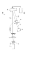
- FIG. 1 is a diagram illustrating a configuration of the spatial light modulation device according to the first embodiment.
- FIG. 2 is a side sectional view showing a part of the configuration of the spatial light modulator.
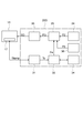
- FIG. 3 is a block diagram illustrating a configuration of the control unit of the first embodiment.
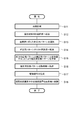
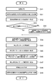
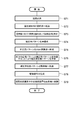
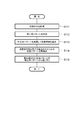
- FIG. 4 is a flowchart illustrating the operation of the spatial light modulation device according to the first embodiment.
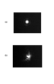
- FIG. 5 is an image showing a light spot shape when the outgoing light image is condensed through the lens.
- FIG. 6 is a graph showing the effect of the first embodiment.
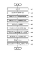
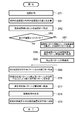
- FIG. 7 is a flowchart showing an example of the operation of the spatial light modulation device when the spatial light modulation element has a plurality of temperature sensors.
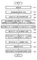
- FIG. 8 is a flowchart showing another example of the operation of the spatial light modulation device when the spatial light modulation element has a plurality of temperature sensors.
- FIG. 9 is a diagram illustrating a configuration example of the control unit when the operation illustrated in FIG. 7 is performed.
- FIG. 10 is a flowchart showing the operation of the control unit having another storage unit that temporarily holds the correction pattern.
- FIG. 11 is a flowchart showing the operation of the control unit according to the first modification.
- FIG. 12 is a block diagram illustrating a configuration of a control unit according to the second embodiment.
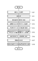
- FIG. 13 is a flowchart showing the operation of the spatial light modulation device according to the second embodiment.
- FIG. 14 is an image showing an example of a correction pattern acquired by interference measurement.
- FIG. 14 is an image showing an example of a correction pattern acquired by interference measurement.
- FIG. 15 shows a correction pattern in a case where a coefficient value group is calculated using a Legendre power polynomial which is one of orthonormal function systems up to a tenth order coefficient, and a correction pattern is reconstructed from the coefficient value group. It is an image which shows an example.
- FIG. 16 is a flowchart illustrating an example of an operation when the control unit has a coefficient value memory that temporarily holds a coefficient value group in the second embodiment.
- FIG. 17 is a flowchart illustrating an example of an operation when the control unit has another storage unit that temporarily holds the reconstructed correction pattern in the second embodiment.
- FIG. 18 is a flowchart showing a spatial light modulation method in a case where a coefficient value group corresponding to a temperature value between N temperature values is obtained by performing interpolation of the N coefficient value groups.
- FIG. 19 is a graph for explaining an example of a coefficient value group interpolation calculation method in the coefficient value group estimation unit.
- FIG. 20 is a graph for explaining another example of the coefficient value group interpolation calculation method in the coefficient value group estimation unit.
- FIG. 21 is a flowchart showing the operation of the control unit according to the second modification.
- FIG. 22 is a block diagram illustrating a configuration of a control unit according to the third embodiment.
- FIG. 23 is a flowchart showing the operation of the spatial light modulation device according to the third embodiment.
- FIG. 24 is a flowchart illustrating an example of an operation when the control unit has a coefficient value memory that temporarily holds a coefficient value group in the third embodiment.
- FIG. 25 is a flowchart illustrating an example of an operation when the control unit has another storage unit that temporarily holds the reconstructed correction pattern in the third embodiment.
- FIG. 26 is a block diagram illustrating a configuration of a control unit according to the fourth embodiment.
- FIG. 27 is a flowchart showing the operation of the spatial light modulation device according to the fourth embodiment.
- FIG. 28 is a graph showing the effect of the fourth embodiment.
- FIG. 29 is a flowchart illustrating an example of a method for creating a function and a reference phase pattern.
- FIG. 30 is a diagram illustrating a configuration of a control unit including a selection unit that selects one reference phase pattern from a plurality of reference phase patterns stored in the storage unit.
- FIG. 31 is a flowchart illustrating an example of an operation when the control unit has another storage unit that temporarily holds the reconstructed correction pattern in the fourth embodiment.
- FIG. 32 is a flowchart showing the operation of the control unit according to the third modification.
- FIG. 33 is a block diagram illustrating a configuration of a control unit according to the fifth embodiment.
- FIG. 34 is a flowchart showing the operation of the spatial light modulation device according to the fifth embodiment.
- FIG. 35 is a flowchart illustrating an example of the operation of the control unit having another storage unit that temporarily holds the reconstructed correction pattern in the fifth embodiment.
- FIG. 36 is a flowchart showing the operation of the control unit according to the fourth modification.
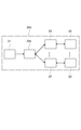
- FIG. 1 is a diagram showing a configuration of a spatial light modulation device according to the first embodiment of the present invention.
- the spatial light modulation device 1A includes a light source 2, a spatial filter 3, a collimating lens 4, a Fourier transform lens 5, a spatial light modulation element 10, and a control unit 20A.
- the light L1 emitted from the light source 2 passes through the spatial filter 3 and the collimating lens 4 to become a light image L2.
- This light image L2 is incident on the spatial light modulator 10.
- the phase of the optical image L2 is modulated for each of a plurality of pixels in accordance with the drive signal SD given from the control unit 20A.
- the phase-modulated optical image L3 is output from the spatial light modulator 10.
- the optical image L3 passes through the Fourier transform lens 5 to become a Fourier optical image L4, and the Fourier optical image L4 is irradiated to the workpiece 6.
- FIG. 2A is a side sectional view showing a part of the configuration of the spatial light modulator 10.
- the spatial light modulator 10 includes a silicon substrate 11 and a liquid crystal layer 12 provided on the silicon substrate 11.
- the spatial light modulator 10 is provided at a position where the liquid crystal layer 12 is sandwiched between the first electrode 13 disposed between the silicon substrate 11 and the liquid crystal layer 12 and the first electrode 13.
- a second electrode 14 is further provided.
- the first electrode 13 has a plurality of pixel electrodes 13 a for applying a voltage to the liquid crystal layer 12.
- the plurality of pixel electrodes 13a are two-dimensionally arranged over a plurality of rows and a plurality of columns, and a plurality of pixels of the spatial light modulator 10 are defined by these pixel electrodes 13a.
- a reflective mirror 18 is disposed between the plurality of pixel electrodes 13 a and the liquid crystal layer 12.
- the second electrode 14 is made of a metal film deposited on one surface of the glass substrate 15.
- the glass substrate 15 is supported on the silicon substrate 11 via a spacer 16 so that the one surface and the silicon substrate 11 face each other.
- the liquid crystal layer 12 is formed by filling a liquid crystal between the silicon substrate 11 and the glass substrate 15.
- the liquid crystal layer 12 has an alignment film 19 a in a region along the glass substrate 15, and an alignment film 19 b in a region along the reflecting mirror 18. Have.
- an analog signal voltage is applied between each pixel electrode 13a and the second electrode 14 based on the drive signal SD output from the control unit 20A.
- an electric field is generated in the liquid crystal layer 12.
- the liquid crystal molecules 12a on each pixel electrode 13a rotate by an angle corresponding to the magnitude of the applied electric field. Since the liquid crystal molecules 12a have birefringence, when light is transmitted through the glass substrate 15, only a light component parallel to the electric field is given a phase difference corresponding to the tilt angle of the liquid crystal molecules 12a. It is done. In this way, the phase of light is modulated for each pixel electrode 13a.
- the spatial light modulation element 10 of the present embodiment further includes a temperature sensor 17 in order to correct such variation due to temperature change.
- the temperature sensor 17 is provided to detect the temperature of the spatial light modulation element 10 and generates a temperature signal that is a signal corresponding to the temperature of the spatial light modulation element 10.
- the temperature sensor 17 is disposed on, for example, the silicon substrate 11 or the glass substrate 15.
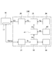
- FIG. 3 is a block diagram showing the configuration of the control unit 20A.
- the control unit 20 ⁇ / b> A includes a temperature sensor control unit 21, a storage unit 22, a selection unit 23, a computer generated hologram creation unit 24, a computer generated hologram calculation unit 25, and a drive unit 26.
- the temperature sensor control unit 21 obtains a temperature signal Stemp from the temperature sensor 17 of the spatial light modulator 10 and performs a predetermined calculation on the temperature signal Stemp to obtain a temperature value Ts of the spatial light modulator 10.
- the temperature sensor control unit 21 provides the obtained temperature value Ts to the selection unit 23.
- the storage unit 22 is a storage unit in the present embodiment, and stores N correction patterns (N is an integer of 2 or more).
- the N correction patterns correspond to the N temperature values of the spatial light modulator 10 in order to correct the phase distortion of the emitted light image L3 caused by the temperature change of the spatial light modulator 10.
- the phase pattern is created in advance.
- Each correction pattern is data including a plurality of correction phase values corresponding to each of the plurality of pixels of the spatial light modulator 10.
- the storage unit 22 is preferably configured by, for example, a RAM (Random Access Memory) or the like.
- the selection unit 23 selects one correction pattern corresponding to the temperature value closest to the temperature value Ts from among the N correction patterns based on the temperature value Ts provided from the temperature sensor control unit 21.
- the correction pattern is read from the storage unit 22.
- the selection unit 23 provides the read correction pattern P1 to the computer generated hologram calculation unit 25.
- the computer generated hologram creation unit 24 creates a computer generated hologram (Computer Generated Hologram; CGH) having a desired phase pattern.
- This computer generated hologram includes a plurality of pixel components, and each pixel component represents a desired phase modulation amount in each of the plurality of pixels of the spatial light modulator 10.
- the computer generated hologram creating unit 24 provides the computer generated hologram (desired phase pattern) P ⁇ b> 2 to the computer generated hologram calculation unit 25.
- the computer generated hologram calculation unit 25 corrects the influence of the temperature change of the spatial light modulator 10 by adding the phase modulation amount included in the computer generated hologram P2 and the correction phase value included in the correction pattern P1 for each pixel.
- a corrected phase pattern (hereinafter referred to as a corrected phase pattern) is created.
- the computer generated hologram calculation unit 25 provides the corrected phase pattern P3 thus created to the drive unit 26.
- the drive unit 26 generates a drive signal SD based on the corrected phase pattern P3 provided from the computer generated hologram calculation unit 25. Specifically, based on the phase modulation amount for each pixel included in the corrected phase pattern P3, a voltage value applied to each of the plurality of pixel electrodes 13a (see FIG. 2) of the spatial light modulator 10 is calculated. A drive signal SD indicating these voltage values is generated. The drive unit 26 provides the generated drive signal SD to the spatial light modulator 10.
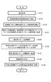
- FIG. 4 is a flowchart showing the operation of the spatial light modulation device 1A.
- the spatial light modulation method of this embodiment will be described together with the spatial light modulation device 1A with reference to FIG.
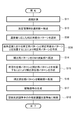
- the temperature sensor control unit 21 acquires the temperature signal Stemp from the temperature sensor 17, and obtains the current temperature value Ts of the spatial light modulator 10 based on the temperature signal Stemp (Temperature acquisition step S11). Information about the temperature value Ts is transferred from the temperature sensor control unit 21 to the selection unit 23 (step S12). Next, the selection unit 23 selects a correction pattern P1 having a temperature value closest to the temperature value Ts from the N correction patterns stored in the storage unit 22 based on the temperature value Ts. (Correction pattern selection step S13). The correction pattern P1 is transferred to the computer generated hologram calculation unit 25 (step S14).
- the computer generated hologram calculation unit 25 adds (synthesizes) the computer generated hologram (desired phase pattern) P2 provided from the computer generated hologram generation unit 24 and the correction pattern P1, thereby obtaining the corrected phase pattern P3.
- Create step S15).
- the corrected phase pattern P3 is transferred from the computer generated hologram calculation unit 25 to the drive unit 26 (step S16).
- the drive unit 26 generates a drive signal SD based on the corrected phase pattern P3 (drive signal generation step S17).
- the phase modulation amount for each of the plurality of pixels included in the spatial light modulator 10 is controlled by the drive signal SD (Modulation control step S18). That is, when the drive signal SD is provided to the spatial light modulator 10, a voltage corresponding to the phase modulation amount indicated by the corrected phase pattern P3 is applied to each pixel electrode 13a.
- the inclination of the liquid crystal molecules 12a changes according to the magnitude of the applied voltage, and the refractive index changes.
- the phase distribution corresponding to the corrected phase pattern P3 is spatially expressed, and the phase of the incident light is modulated.
- the spatial light modulation device 1A and the spatial light modulation method of the present embodiment having the above-described configuration will be described.
- the silicon substrate 11 warps due to the difference in thermal expansion coefficients of the silicon substrate 11 and the pixel electrode 13a shown in FIG.
- Such warpage of the silicon substrate 11 causes an error in the phase modulation amount of the reflected light of each pixel, and distorts the phase distribution in the entire reflected light image. Therefore, in the conventional apparatus, a phase modulation characteristic different from the phase modulation characteristic desired to be added by the computer generated hologram is obtained in the output light image.
- FIG. 5 is an image showing a light spot shape when the outgoing light image is condensed through the lens.
- the spatial light modulation device 1A and the spatial light modulation method of the present embodiment different correction patterns are used for each of a plurality of temperature values of the spatial light modulation element 10, so that the spatial light modulation The distortion of the phase distribution accompanying the temperature change of the element 10 can be suitably suppressed.
- the processing in the control unit 20A since the processing in the control unit 20A only needs to select and add one correction pattern P1 according to the temperature value Ts, the operation delay can be suppressed to be small.
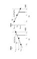
- FIG. 6 is a graph showing the effect of this embodiment.
- N 8 in this example
- the relationship between the temperature of the spatial light modulator 10 and the root mean square (unit: wavelength ⁇ ) of the phase distortion is shown.
- a graph G12 shown in FIG. 6 measures the phase distortion of the emitted light image L3 in the spatial light modulation element 10 at a certain reference temperature (in this example, 27 ° C.).
- a certain reference temperature in this example, 27 ° C.
- the phase distortion changes sensitively to a temperature change of the spatial light modulator 10.
- N correction patterns corresponding to a plurality of temperature values as in this embodiment, there is a measurement error as shown in the graph G11. Distortion can be suppressed to 1/10 or less of the phase modulation amount ⁇ .
- the spatial light modulation device 1A and the spatial light modulation method of the present embodiment since only the temperature sensor 17 is required as a component added to the spatial light modulation device 1A, the above-described problems can be solved at a low manufacturing cost. it can. Further, when a temperature control means such as a Peltier element is attached to the outside of the spatial light modulation element 10, a temperature gradient is generated between the contact portion of the spatial light modulation element 10 with the temperature control means and another part. . Even in such a case, according to the present embodiment, the phase distortion given to the outgoing light image by this temperature gradient can be alleviated. In addition, phase distortion caused by physical deterioration of the spatial light modulator 10 by forced temperature control can be reduced.
- a temperature control means such as a Peltier element
- an electrical address type liquid crystal element is exemplified as the spatial light modulation element 10, but other examples of the spatial light modulation element 10 include an optical address type liquid crystal element and a variable mirror type modulation element. Various spatial light modulation elements can be applied.
- the attachment position (that is, the temperature measurement position) of the temperature sensor 17 in the spatial light modulation element 10 is inside the casing of the spatial light modulation element 10 (measuring the temperature in the casing), and in the spatial light modulation element 10. Outside the housing (measuring the outside air temperature of the housing), the surface of the glass substrate 15 of the spatial light modulator 10, the back surface of the silicon substrate 11 of the spatial light modulator 10, the incident position of the incident light image L2, and the space serving as the heat source It is preferable that it is any one place in the circuit of the light modulation element 10. Or you may arrange
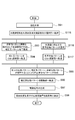
- the spatial light modulator 1A may operate according to the flowchart shown in FIG. First, the temperature sensor 17 used for measurement is selected from the plurality of temperature sensors 17 (step S21). Next, based on the temperature signal Stemp provided from the selected temperature sensor 17, the temperature sensor control unit 21 obtains the current temperature value Ts of the spatial light modulator 10 (temperature acquisition step S11). Thereafter, the same processing as steps S12 to S18 (see FIG. 4) in the above-described embodiment is performed. In order for the spatial light modulation device 1 ⁇ / b> A to perform such an operation, a correction pattern corresponding to each temperature value measured for each of the plurality of temperature sensors 17, the temperature sensor 17, and the temperature value in the storage unit 22. It is preferable that an information table for associating each other is held in advance.
- the spatial light modulation device 1A can further exhibit the following effects by performing the above operation.
- the optimum position for measuring the temperature of the spatial light modulator 10 may vary depending on how the spatial light modulator 10 is used. For example, when the outside air temperature with which the spatial light modulator 10 is in contact is low and the internal circuit of the spatial light modulator 10 becomes a heat source and the internal temperature is high, a temperature gradient is generated inside the spatial light modulator 10 or It may be difficult to perform accurate temperature correction only by measuring the temperature at one specific position.
- the spatial light modulator 10 has a plurality of temperature sensors 17, and the spatial light modulator 1A performs the above-described operation, so that the temperature of the spatial light modulator 10 at a preferred temperature measurement position. Can be measured.
- the temperature sensor control unit 21 uses an external signal input mechanism (for example, RS232C, GPIB, USB, Ethernet (registered trademark)). Etc.).
- the spatial light modulator 1A may operate according to the flowchart shown in FIG. First, two or more temperature sensors 17 used for measurement are selected from a plurality of temperature sensors 17 (step S22). Next, based on the two or more temperature signals Stemp provided from the two or more selected temperature sensors 17, the temperature sensor control unit 21 obtains two or more temperature values corresponding to them (step S23). Then, an average value of these temperature values or a temperature correction value weighted according to the measurement location is calculated, and the value is set as a temperature value Ts (step S24). Thereafter, the same processing as steps S12 to S18 (see FIG. 4) in the above-described embodiment is performed.
- the temperature correction value may be calculated by using a correction coefficient derived by estimating a heat distribution by a heat conduction equation or a finite element method.
- each storage unit 22 and one selection unit 23 can be handled independently. For example, when it is desired to update only one correction pattern, only the corresponding storage unit 22 needs to be updated. In addition, since the capacity of each storage unit 22 is small, an expensive large-capacity storage element need not be used. As shown in FIG. 9, the control unit 20A further includes another selection unit 23a for selecting one storage unit 22 and selection unit 23 from the plurality of storage units 22 and selection unit 23. Further preferred.
- the temperature sensor control unit 21 holds in advance N temperature values corresponding to the N correction patterns.
- the temperature information of the temperature signal Stemp is preprocessed, such as selecting one temperature value from these N temperature values based on the temperature signal Stemp, or multiplying the temperature signal Stemp by a correction coefficient.
- the temperature value Ts may be generated.
- the storage unit 22 stores in advance a temperature information table for associating the N correction patterns with the N temperature values. It is good to leave. Further, the N correction patterns may be stored after being compressed, and in that case, an image processing unit for performing image decompression may be further provided before or after the selection unit 23.
- the storage unit 22 preferably has a certain large capacity.
- the correction pattern is an 8-bit image with SVGA resolution (800 pixels ⁇ 600 pixels).
- the control unit 20A includes the storage unit 22 that can store such a large amount of data. It is preferable to provide.
- the selected correction pattern P1 is temporarily held.
- a separate storage unit for example, a frame memory
- the control unit 20A stores a temperature value corresponding to the correction pattern stored in another storage unit, and the difference between the temperature value and the current temperature value Ts. It is preferable to further have a means for calculating. If the difference is smaller than the threshold value, the correction pattern stored in the other storage unit may be transferred to the computer generated hologram calculation unit 25. Even when high-accuracy temperature correction is required, such a configuration is possible by using a high-speed response memory as the separate storage unit.
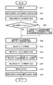
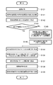
- FIG. 10 is a flowchart showing the operation of the control unit 20A having such a configuration.
- the temperature sensor control unit 21 obtains the current temperature value of the spatial light modulator 10 (temperature acquisition step S11).
- the difference between the previously calculated temperature value and the current temperature value is calculated (step S31).
- the current temperature value is stored in another storage unit, and the current temperature value and the difference are transferred to the selection unit 23 (step S32).
- the selection unit 23 determines the difference between the difference and the threshold (step S33), and if the difference is smaller than the threshold (Yes in step S33), the correction pattern stored in another storage unit is used as the computer generated hologram calculation unit. 25 (step S36).
- the selection unit 23 selects one correction pattern from the N correction patterns stored in the storage unit 22, and selects the correction pattern. Transfer to another storage unit (step S37). Further, this correction pattern is transferred from another storage unit to the computer generated hologram calculation unit 25 (step S36). Thereafter, the same processing as steps S15 to S18 (see FIG. 4) in the above-described embodiment is performed.
- the storage unit 22 stores a correction pattern at a certain reference temperature, and N correction patterns that are differences between the correction pattern at the reference temperature and the correction pattern at each temperature.
- the difference pattern is stored. That is, the correction differential pattern is information indicating how the phase distortion has changed when the temperature has changed from the reference temperature to each temperature, and is added (synthesized) to the phase distortion correction pattern at the reference temperature.
- the storage unit 22 of the present modification stores substantially N correction patterns by storing the correction patterns at the reference temperature and the N correction difference patterns at other temperatures. ing.
- FIG. 11 is a flowchart showing the operation of the control unit 20A having such a configuration.
- the temperature sensor control unit 21 acquires the temperature signal Stemp from the temperature sensor 17, and obtains the current temperature value Ts of the spatial light modulator 10 based on the temperature signal Stemp (Temperature acquisition step S11). Information about the temperature value Ts is transferred from the temperature sensor control unit 21 to the selection unit 23 (step S12).
- the selection unit 23 selects a correction differential pattern corresponding to the temperature value closest to the temperature value Ts from the correction patterns stored in the storage unit 22 based on the temperature value Ts ( Correction pattern selection step S38). Then, the selection unit 23 adds (synthesizes) the correction pattern corresponding to the reference temperature and the correction difference pattern, thereby creating a correction pattern P1 corresponding to the temperature value (step S39). The correction pattern P1 is transferred to the computer generated hologram calculation unit 25 (step S14). Thereafter, the same processing as steps S15 to S18 (see FIG. 4) in the above-described embodiment is performed.
- the storage unit 22 may substantially store N correction patterns by various methods. Even in such a case, the operational effects according to the above-described embodiment can be suitably exhibited.
- the temperature sensor 17 to be used for measurement is selected from the plurality of temperature sensors 17 and provided from the selected temperature sensor 17.
- the temperature sensor control unit 21 may obtain the current temperature value Ts of the spatial light modulator 10 based on the temperature signal Stemp (see FIG. 7).
- one storage unit 22 and one selection unit 23 may be provided for each temperature sensor 17 (see FIG. 9).
- two or more temperature sensors 17 used for measurement are selected from the plurality of temperature sensors 17, and the temperature sensor control unit 21 is based on two or more temperature signals Stemp provided from the selected two or more temperature sensors 17. Obtains two or more temperature values corresponding to these, calculates an average value of these temperature values, or a temperature correction value weighted according to the measurement location, and may use the value as the temperature value Ts (see FIG. 8). ). In this case, one storage unit 22 and one selection unit 23 may be provided for each combination of the temperature sensors 17.
- the temperature sensor control unit 21 holds in advance N temperature values corresponding to the N correction difference patterns, and based on the temperature signal Stemp,
- the temperature value Ts may be generated by pre-processing the temperature information of the temperature signal Stemp, such as selecting one temperature value from the above, or multiplying the temperature signal Stemp by a correction coefficient.
- the storage unit 22 stores in advance a temperature information table for associating the N correction difference patterns with the N temperature values in addition to the N correction difference patterns. It is good to keep.
- the N correction difference patterns may be stored after being compressed, and in that case, an image processing unit for performing image decompression may be further provided in the preceding stage or the subsequent stage of the selection unit 23.
- the storage unit 22 can store a large amount of data.
- the combined correction pattern P1 is temporarily held.
- a separate storage unit for example, a frame memory
- the control unit 20A stores a temperature value corresponding to the correction pattern stored in another storage unit, and the difference between the temperature value and the current temperature value Ts. It is preferable to further have a means for calculating. When this difference is smaller than the threshold value, the correction pattern stored in the other storage unit may be transferred to the computer generated hologram calculation unit 25 (see FIG. 10).
- the spatial light modulation device of the present embodiment includes the light source 2, the spatial filter 3, the collimating lens 4, the Fourier transform lens 5, and the spatial light modulation element 10 shown in FIG. Yes. These configurations are the same as those in the first embodiment.
- the spatial light modulation device of the present embodiment includes a control unit described below instead of the control unit 20A of the first embodiment.
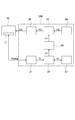
- FIG. 12 is a block diagram illustrating a configuration of the control unit 20B included in the spatial light modulation device according to the present embodiment.
- the control unit 20B includes a temperature sensor control unit 21, a computer generated hologram creation unit 24, a computer generated hologram calculation unit 25, a drive unit 26, a storage unit 27, a selection unit 28, and a correction pattern reconstruction unit. 29.
- the configurations of the temperature sensor control unit 21, the computer generated hologram creation unit 24, the computer generated hologram calculation unit 25, and the drive unit 26 are the same as those in the first embodiment.
- the storage unit 27 is a storage unit in the present embodiment, and stores N (N is an integer of 2 or more) coefficient value groups (coefficient value sequences).
- N coefficient value groups are coefficients calculated in advance from each of the N correction patterns in the first embodiment, and one or a plurality of coefficients are calculated for one correction pattern.
- One or a plurality of coefficients constitute one coefficient value group.
- the coefficient value group is calculated from the correction pattern, which is two-dimensional image data, using a calculation method for expressing a three-dimensional plane such as an orthonormal function system, a spline curve, and a two-dimensional least square method.
- the storage unit 27 is preferably configured by a RAM or the like, for example.
- the selection unit 28 selects one coefficient value group corresponding to the temperature value closest to the temperature value Ts from among the N coefficient value groups based on the temperature value Ts provided from the temperature sensor control unit 21.
- the coefficient value group is read from the storage unit 27.
- the selection unit 28 provides the read coefficient value group A1 to the correction pattern reconstruction unit 29.
- the correction pattern reconstruction unit 29 reconstructs one correction pattern P1 from the coefficient value group A1 transferred from the selection unit.
- the correction pattern reconstruction unit 29 provides the generated correction pattern P1 to the computer generated hologram calculation unit 25.
- FIG. 13 is a flowchart showing the operation of the spatial light modulation device according to this embodiment. With reference to FIG. 13, the spatial light modulation method of this embodiment will be described along with the operation of the spatial light modulation device.
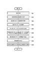
- the temperature sensor control unit 21 acquires the temperature signal Stemp from the temperature sensor 17, and obtains the current temperature value Ts of the spatial light modulator 10 based on the temperature signal Stemp (Temperature acquisition step S41). Information regarding the temperature value Ts is transferred from the temperature sensor control unit 21 to the selection unit 28 (step S42). Next, the selection unit 28 selects a coefficient value group A1 corresponding to the temperature value closest to the temperature value Ts from among the N coefficient value groups stored in the storage unit 27 based on the temperature value Ts. Select (coefficient value group selection step S43). The coefficient value group A1 is transferred to the correction pattern reconstruction unit 29. Then, the correction pattern reconstruction unit 29 reconstructs one correction pattern P1 from the coefficient value group A1 transferred from the selection unit 28 (step S44). The reconstructed correction pattern P1 is transferred to the computer generated hologram calculation unit 25 (step S45).
- the computer generated hologram calculation unit 25 adds (synthesizes) the computer generated hologram (desired phase pattern) P2 provided from the computer generated hologram generation unit 24 and the correction pattern P1, thereby obtaining the corrected phase pattern P3.
- the corrected phase pattern P3 is transferred from the computer generated hologram calculation unit 25 to the drive unit 26 (step S47).
- the drive unit 26 generates a drive signal SD based on the corrected phase pattern P3 (drive signal generation step S48).
- the phase modulation amount for each of the plurality of pixels included in the spatial light modulator 10 is controlled by the drive signal SD (Modulation control step S49).
- the spatial light modulation device and the spatial light modulation method of the present embodiment having the above-described configuration, it is possible to suitably suppress the distortion of the phase distribution accompanying the temperature change of the spatial light modulation element 10.
- the processing in the control unit 20B since the processing in the control unit 20B only needs to select one coefficient value group A1 according to the temperature value Ts, reconstruct and add the correction pattern P1, operation delay can be suppressed to a small value.
- the correction pattern has a gradual phase inclination generated in an optical system such as the spatial filter 3, the collimating lens 4, and the Fourier transform lens 5 in FIG. This is effective when it is composed of low spatial frequency components.
- the amount of data stored in the storage unit 27 can be significantly compressed as compared with the first embodiment.
- each correction pattern has a data amount of, for example, 480 kilobytes.
- the correction pattern having such a data amount is represented by approximately 55 coefficient values. If all of these coefficient values are 32-bit signed single precision floating point type data, the data amount is 220 bytes in total, and the data amount is compressed to about 0.5% of the information amount compared to the uncompressed image. Can do.
- FIG. 14 is an image showing an example of a correction pattern acquired by interference measurement.
- the spatial light modulator 10 for example, 8-bit two-dimensional image data is used to express phase values 0 ⁇ to 2 ⁇ .
- the phase value 0 ⁇ represents the 0 gradation value
- the phase value 2 ⁇ represents the 255 gradation value.
- a remainder value obtained by dividing by 2 ⁇ is applied, so that a region (hereinafter referred to as “turned back” from 255 gradation values to 0 gradation values in 8-bit image data). This is called a folded area).
- FIG. 1 8-bit two-dimensional image data is used to express phase values 0 ⁇ to 2 ⁇ .
- the phase value 0 ⁇ represents the 0 gradation value
- the phase value 2 ⁇ represents the 255 gradation value.
- a remainder value obtained by dividing by 2 ⁇ is applied, so that a region (hereinafter referred to as “turned back” from 255 gradation values to 0 gradation values in 8-bit
- FIG. 15 shows a correction pattern in a case where a coefficient value group is calculated using a Legendre power polynomial which is one of orthonormal function systems up to a tenth order coefficient, and a correction pattern is reconstructed from the coefficient value group. It is an image which shows an example. As shown in FIG. 15, it can be seen that even when the correction pattern is reconstructed using the coefficient value sequence, a correction pattern substantially similar to that in FIG. 14 can be generated.
- various spatial light modulation elements such as an optical address type liquid crystal element and a variable mirror type modulation element can be applied as the spatial light modulation element 10 in addition to the electrical address type liquid crystal element.
- the attachment position of the temperature sensor 17 in the spatial light modulation element 10 is within the casing of the spatial light modulation element 10, outside the casing of the spatial light modulation element 10, and the glass substrate 15 of the spatial light modulation element 10. Is preferably one of the front surface, the back surface of the silicon substrate 11 of the spatial light modulation element 10, the incident position of the incident light image L2, and the inside of the circuit of the spatial light modulation element 10 serving as a heat source. Or you may arrange
- the spatial light modulator 10 may operate as follows, for example. First, the temperature sensor 17 used for measurement is selected from the plurality of temperature sensors 17. Next, based on the temperature signal Stemp provided from the selected temperature sensor 17, the temperature sensor control unit 21 obtains the current temperature value Ts of the spatial light modulator 10. Thereafter, processing similar to that in steps S42 to S49 (see FIG. 13) in the present embodiment is performed. In order for the spatial light modulation device to perform such an operation, in the storage unit 27, the coefficient value group corresponding to each temperature value measured for each of the plurality of temperature sensors 17, the temperature sensor 17 and the temperature value are stored. It is preferable that an information table for associating with each other is held in advance.
- the spatial light modulator 10 may operate as follows. First, two or more temperature sensors 17 used for measurement are selected from a plurality of temperature sensors 17. Next, based on the two or more temperature signals Stemp provided from the two or more selected temperature sensors 17, the temperature sensor control unit 21 obtains two or more temperature values corresponding to these. And the temperature correction value weighted according to the average value of these temperature values or the measurement location is calculated, and let that value be the temperature value Ts. Thereafter, the same processing as in steps S42 to S49 (see FIG. 13) in the above-described embodiment is performed.
- the temperature at a plurality of locations is simultaneously measured using the plurality of temperature sensors 17 as described above, and the average value or the temperature correction value thereof is used.
- the accuracy of temperature correction can be further increased.
- the temperature correction value may be calculated by using a correction coefficient derived by estimating a heat distribution by a heat conduction equation or a finite element method.
- one storage unit 27 and one selection unit 28 may be provided for each temperature sensor 17.
- one storage unit 27 and one selection unit 28 may be provided for a plurality of combinations of the temperature sensors 17. According to these configurations, each storage unit 27 and each selection unit 28 can be handled independently. In addition, since the capacity of each storage unit 27 can be small, an expensive large-capacity storage element need not be used. It is more preferable that the control unit 20B further includes another selection unit for selecting one storage unit 27 and selection unit 28 from the plurality of storage units 27 and selection units 28.
- the temperature sensor control unit 21 holds in advance N temperature values corresponding to the N correction patterns.
- the temperature information of the temperature signal Stemp is preprocessed, such as selecting one temperature value from these N temperature values based on the temperature signal Stemp, or multiplying the temperature signal Stemp by a correction coefficient.
- the temperature value Ts may be generated.
- a coefficient value memory that temporarily holds the selected coefficient value group A1 is provided in the control unit 20B, and the coefficient value group A1 is appropriately read out from the coefficient value memory.
- the operation frequency of the selection unit 28 may be reduced.
- the control unit 20B includes, in addition to the coefficient value memory, a means for storing a temperature value corresponding to the coefficient value group A1 stored in the coefficient value memory, and a difference between the temperature value and the current temperature value Ts. It is preferable to further have a means for calculating. If the difference is smaller than the threshold value, the coefficient value group A1 stored in the coefficient value memory may be transferred to the correction pattern reconstruction unit 29.
- FIG. 16 is a flowchart showing an example of the operation of the control unit 20B having such a configuration.
- the temperature sensor control unit 21 obtains the current temperature value of the spatial light modulator 10 (temperature acquisition step S41).
- the difference between the previously calculated temperature value and the current temperature value is calculated (step S51).
- the current temperature value is stored in another storage unit, and the current temperature value and the difference are transferred to the selection unit 28 (step S52).
- the selection unit 28 determines the difference between the difference and the threshold value (step S53). When the difference is smaller than the threshold value (Yes in step S53), the coefficient value group A1 stored in the coefficient value memory is used for correction.
- the data is transferred to the pattern reconstruction unit 29 (step S54).
- the selection unit 28 selects one coefficient value group A1 from the N coefficient value groups stored in the storage unit 27, and The coefficient value group A1 is transferred to the coefficient value memory (step S55). Further, the coefficient value group A1 is transferred from the coefficient value memory to the correction pattern reconstruction unit 29 (step S54). Thereafter, processing similar to that in steps S44 to S49 (see FIG. 13) in the present embodiment is performed.
- the correction pattern P1 reconstructed by the coefficient value group A1.
- the control unit 20B stores a temperature value corresponding to the correction pattern P1 stored in another storage unit, and the temperature value and the current temperature value Ts. It is preferable to further have a means for calculating the difference.
- the correction pattern P1 stored in the other storage unit may be transferred to the computer generated hologram calculation unit 25. Even when high-accuracy temperature correction is required, such a configuration is possible by using a high-speed response memory as the separate storage unit.
- FIG. 17 is a flowchart showing an example of the operation of the control unit 20B having such a configuration.
- step S53 up to step S53 is the same as the operation shown in FIG.
- the correction pattern P1 stored in another storage unit is transferred to the computer generated hologram calculation unit 25 (step S56).
- the selection unit 28 selects one coefficient value group A1 from the N coefficient value groups stored in the storage unit 27, and The coefficient value group A1 is transferred to the coefficient value memory (step S57). Further, the coefficient value group A1 is transferred from the coefficient value memory to the correction pattern reconstruction unit 29 (step S58).
- the correction pattern reconstruction unit 29 reconstructs one correction pattern P1 from the coefficient value group A1 (step S59).
- the reconstructed correction pattern P1 is transferred to the computer generated hologram calculation unit 25 (step S56). Thereafter, processing similar to that in steps S46 to S49 (see FIG. 13) in the present embodiment is performed.
- coefficient value groups corresponding to temperature values between N temperature values may be obtained by interpolating N coefficient value groups.
- FIG. 18 is a flowchart showing a spatial light modulation method including such an interpolation method.
- the temperature sensor control unit 21 obtains the current temperature value Ts of the spatial light modulator 10 (temperature acquisition step S41). Information regarding the temperature value Ts is transferred from the temperature sensor control unit 21 to the selection unit 28 (step S42).
- the selection unit 28 selects two coefficient value groups corresponding to the temperature values before and after the temperature value Ts from among the N coefficient value groups stored in the storage unit 27 based on the temperature value Ts. Is selected (step S60).
- coefficient value groups are transferred to a coefficient value group estimation unit provided between the selection unit 28 and the correction pattern reconstruction unit 29. Then, the coefficient value group estimation unit calculates one coefficient value group by performing interpolation calculation based on the two coefficient value groups transferred from the selection unit 28 (step S61). The calculated coefficient value group is transferred to the correction pattern reconstruction unit 29. The correction pattern reconstruction unit 29 reconstructs one correction pattern P1 from the coefficient value group transferred from the coefficient value group estimation unit (step S62). Thereafter, processing similar to that in steps S45 to S49 (see FIG. 13) in the present embodiment is performed.
- FIGS. 19A and 19B are graphs for explaining an example of a coefficient value group interpolation calculation method in the coefficient value group estimation unit.
- the horizontal axis of this graph represents the temperature value
- the vertical axis represents the coefficient value.
- These coefficients k 1, k 2, ⁇ , k m has a different value for each of N coefficient group.
- the coefficient value k 1 values of k 1n corresponding to the temperature value t n the value of the coefficient value k 1 corresponding to the temperature value t n + 1 and k 1 (n + 1).
- FIG. 19 (a) the coefficient value k 1 values of k 1n corresponding to the temperature value t n, the value of the coefficient value k 1 corresponding to the temperature value t n + 1 and k 1 (n + 1).
- FIG. 19 (a) the coefficient value k 1 values of
- coefficient value k m a m t + b m It is expressed.
- coefficient values k 10 , k 20 ,..., Km 0 corresponding to the temperature value t 0 (t n ⁇ t 0 ⁇ t n + 1 ) can be easily obtained.
- the coefficient value group estimation unit can calculate one coefficient value group including coefficient values k 10 , k 20 ,..., Km 0 by performing such linear interpolation calculation.
- 20 (a) and 20 (b) are graphs for explaining another example of the coefficient value group interpolation calculation method in the coefficient value group estimation unit.
- the selection unit 28 selects a value near the temperature value Ts from the N coefficient value groups stored in the storage unit 27. It is necessary to select three or more coefficient value groups corresponding to the temperature value.
- the coefficient value k 1 corresponding to the temperature value t n ⁇ 1 is represented by k 1 (n ⁇ 1)
- the coefficient value k 1 corresponding to the temperature value t n is represented by k.
- the coefficient value k 1 corresponding to 1 n and the temperature value t n + 1 is k 1 (n + 1) .
- coefficient values k 10 , k 20 ,..., Km 0 corresponding to the temperature value t 0 (t n ⁇ t 0 ⁇ t n + 1 ) can be easily obtained.
- the coefficient value group estimation unit can calculate one coefficient value group including coefficient values k 10 , k 20 ,..., Km 0 by performing such approximate interpolation calculation by the least square method.
- an approximate calculation by the least square method may be performed after adding a weight having a different size for each temperature value.
- linear approximation mentioned above but high order polynomial approximation and exponential approximation may be applied.
- the storage unit 27 stores a correction pattern at a certain reference temperature or a coefficient value group for the correction pattern, and the correction pattern at the reference temperature and the correction pattern at each temperature.
- N coefficient value groups (hereinafter referred to as difference coefficient value groups) are stored.
- the correction difference pattern is information indicating how the phase distortion has changed when the temperature has changed from the reference temperature to each temperature, and is added (synthesized) to the phase distortion correction pattern at the reference temperature.
- the phase distortion correction pattern at each temperature can be calculated.
- the storage unit 27 of the present modification stores substantially the N coefficient values by storing the correction pattern or coefficient value group at the reference temperature and the N difference coefficient value groups at the other temperatures. Remember the group.
- FIG. 21 is a flowchart showing the operation of the control unit 20B having such a configuration.
- the temperature sensor control unit 21 acquires the temperature signal Stemp from the temperature sensor 17, and obtains the current temperature value Ts of the spatial light modulator 10 based on the temperature signal Stemp (Temperature acquisition step S41). Information regarding the temperature value Ts is transferred from the temperature sensor control unit 21 to the selection unit 28 (step S42).
- the selection unit 28 selects a difference coefficient value group corresponding to the temperature value closest to the temperature value Ts from the difference coefficient value groups stored in the storage unit 27 based on the temperature value Ts.
- Coefficient value group selection step S63 The difference coefficient value group is transferred to the correction pattern reconstruction unit 29 together with the coefficient value group or the correction pattern at the reference temperature.
- the correction pattern reconstruction unit 29 reconstructs one correction difference pattern from the difference coefficient value group transferred from the selection unit 28 and, if necessary, one correction pattern from the coefficient value group at the reference temperature. Reconfiguration is performed (step S64).
- the correction pattern reconstruction unit 29 adds (synthesizes) the correction difference pattern and the correction pattern at the reference temperature to generate the correction pattern P1 (step S65). Thereafter, the same processing as in steps S45 to S49 (see FIG. 13) in the above embodiment is performed.
- the storage unit 27 may substantially store N coefficient value groups by various methods. Even in such a case, the operational effects according to the above-described embodiment can be suitably exhibited.
- the temperature sensor 17 to be used for measurement is selected from the plurality of temperature sensors 17 and provided from the selected temperature sensor 17.
- the temperature sensor control unit 21 may obtain the current temperature value Ts of the spatial light modulator 10 based on the temperature signal Stemp.
- one storage unit 27 and one selection unit 28 may be provided for each temperature sensor 17.
- two or more temperature sensors 17 used for measurement are selected from the plurality of temperature sensors 17, and the temperature sensor control unit 21 is based on two or more temperature signals Stemp provided from the selected two or more temperature sensors 17. May obtain two or more temperature values corresponding to these, calculate an average value of these temperature values, or a temperature correction value weighted according to the measurement location, and use the value as the temperature value Ts.
- one storage unit 27 and one selection unit 28 may be provided for each combination of the temperature sensors 17.
- the temperature sensor control unit 21 holds in advance N temperature values corresponding to the N difference coefficient value groups, and among these N temperature values based on the temperature signal Stemp.
- the temperature value Ts may be generated by pre-processing the temperature information of the temperature signal Stemp, such as selecting one temperature value from the above, or multiplying the temperature signal Stemp by a correction coefficient.
- the control unit 20B includes, in addition to the difference coefficient value memory, a means for storing a temperature value corresponding to the difference coefficient value group stored in the difference coefficient value memory, the temperature value, and the current temperature value Ts. It is preferable to further include means for calculating the difference between the two. If the difference is smaller than the threshold value, the difference coefficient value group stored in the difference coefficient value memory may be transferred to the correction pattern reconstruction unit 29.
- a correction difference pattern reconstructed from the difference coefficient value group Alternatively, another storage unit (for example, a frame memory) that temporarily stores the correction pattern P1 synthesized from the correction difference pattern is provided in the control unit 20B, and correction is performed from the other storage unit.
- the operation frequency of the selection unit 28 and the correction pattern reconstruction unit 29 may be reduced by appropriately reading out the difference pattern for correction or the correction pattern P1.
- the control unit 20B stores a temperature value corresponding to the correction differential pattern or the correction pattern P1 stored in another storage unit, the temperature value and the current value.
- the correction pattern P1 generated using the correction difference pattern stored in the other storage unit or the correction pattern P1 stored in the other storage unit May be transferred to the computer generated hologram calculation unit 25.
- a difference coefficient value group corresponding to a temperature value between N temperature values may be obtained by interpolating the N difference coefficient value groups (see FIGS. 18 to 20). ).
- the spatial light modulation device of the present embodiment includes the light source 2, the spatial filter 3, the collimating lens 4, the Fourier transform lens 5, and the spatial light modulation element 10 shown in FIG. Yes. These configurations are the same as those in the first embodiment.
- the spatial light modulation device of the present embodiment includes a control unit described below instead of the control unit 20A of the first embodiment.
- FIG. 22 is a block diagram illustrating a configuration of the control unit 20C included in the spatial light modulation device according to the present embodiment.
- the control unit 20C includes a temperature sensor control unit 21, a computer generated hologram creation unit 24, a computer generated hologram calculation unit 25, a drive unit 26, a storage unit 31, a coefficient value calculation unit 32, and a correction pattern re-generation.
- the component 33 is included.
- the configurations of the temperature sensor control unit 21, the computer generated hologram creation unit 24, the computer generated hologram calculation unit 25, and the drive unit 26 are the same as those in the first embodiment.
- the storage unit 31 is a storage unit in the present embodiment, and a function having a temperature value as a variable for each coefficient value included in N (N is an integer of 2 or more) coefficient value group (coefficient value sequence).
- N is an integer of 2 or more
- coefficient value group coefficient value sequence
- the N coefficient value groups are coefficients calculated in advance from each of the N correction patterns in the first embodiment, and one or a plurality of coefficients are calculated for one correction pattern.
- One or a plurality of coefficients constitute one coefficient value group.
- the coefficient value group is calculated by the same method as in the second embodiment described above.
- the storage unit 31 is preferably configured by a RAM or the like, for example.
- the coefficient value calculation unit 32 calculates one coefficient value group among the N coefficient value groups by applying the temperature value Ts provided from the temperature sensor control unit 21 to the function stored in the storage unit 31. .
- the coefficient value calculation unit 32 provides the calculated coefficient value group A1 to the correction pattern reconstruction unit 33.
- the correction pattern reconstruction unit 33 reconstructs one correction pattern P1 from the coefficient value group A1 transferred from the coefficient value calculation unit 32.
- the correction pattern reconstruction unit 33 provides the generated correction pattern P1 to the computer generated hologram calculation unit 25.
- FIG. 23 is a flowchart showing the operation of the spatial light modulation device according to this embodiment. With reference to FIG. 23, the spatial light modulation method of this embodiment will be described along with the operation of the spatial light modulation device.
- the temperature sensor control unit 21 acquires the temperature signal Stemp from the temperature sensor 17, and obtains the current temperature value Ts of the spatial light modulator 10 based on the temperature signal Stemp (Temperature acquisition step S71). Information about the temperature value Ts is transferred from the temperature sensor control unit 21 to the coefficient value calculation unit 32 (step S72).
- the coefficient value calculation unit 32 sequentially reads out the function of each coefficient value stored in the storage unit 31, and applies the temperature value Ts to these functions. Thereby, each coefficient value corresponding to the temperature value Ts is obtained (coefficient value calculation step S73).
- the coefficient value group A1 including these coefficient values is transferred to the correction pattern reconstruction unit 33.
- the correction pattern reconstruction unit 33 reconstructs one correction pattern P1 from the coefficient value group A1 transferred from the coefficient value calculation unit 32 (step S74).
- the reconstructed correction pattern P1 is transferred to the computer generated hologram calculation unit 25 (step S75).
- the computer generated hologram calculation unit 25 adds (synthesizes) the computer generated hologram (desired phase pattern) P2 provided from the computer generated hologram generation unit 24 and the correction pattern P1, thereby obtaining the corrected phase pattern P3.
- the corrected phase pattern P3 is transferred from the computer generated hologram calculation unit 25 to the drive unit 26 (step S77).
- the drive unit 26 generates a drive signal SD based on the corrected phase pattern P3 (drive signal generation step S78).
- the phase modulation amount for each of the plurality of pixels included in the spatial light modulator 10 is controlled by the drive signal SD (Modulation control step S79).
- the processing in the control unit 20C only needs to calculate the one coefficient value group A1 by applying the temperature value Ts to the function, and reconstruct and add the correction pattern P1, so that the operation delay can be reduced. be able to.
- the amount of data stored in the storage unit 31 can be further compressed as compared with the second embodiment.
- a correction pattern is expressed using a 10th-order Legendre polynomial, and a function having a temperature value as a variable is created by applying a third-order least square method to each coefficient value
- this embodiment reduces the data amount of the storage unit. Can do.
- the present embodiment that can reduce the storage capacity is advantageous.
- the selection part 28 (refer FIG. 12) of 2nd Embodiment can be made unnecessary, a control part can also be simplified.
- the correction pattern is created using a function having the temperature value as a variable, so that correction with high accuracy and high resolution is possible. Furthermore, if the coefficient value group is calculated using only typical orthonormal functions, the calculation time can be reduced.
- various spatial light modulation elements such as an optical address type liquid crystal element and a variable mirror type modulation element can be applied as the spatial light modulation element 10 in addition to the electrical address type liquid crystal element.
- the attachment position of the temperature sensor 17 in the spatial light modulation element 10 is within the casing of the spatial light modulation element 10, outside the casing of the spatial light modulation element 10, and the glass substrate 15 of the spatial light modulation element 10. Is preferably one of the front surface, the back surface of the silicon substrate 11 of the spatial light modulation element 10, the incident position of the incident light image L2, and the inside of the circuit of the spatial light modulation element 10 serving as a heat source. Or you may arrange
- the spatial light modulator 10 may operate as follows, for example. First, the temperature sensor 17 used for measurement is selected from the plurality of temperature sensors 17. Next, based on the temperature signal Stemp provided from the selected temperature sensor 17, the temperature sensor control unit 21 obtains the current temperature value Ts of the spatial light modulator 10. Thereafter, processing similar to that in steps S72 to S79 (see FIG. 23) in the present embodiment is performed.
- the spatial light modulator 10 may operate as follows. First, two or more temperature sensors 17 used for measurement are selected from a plurality of temperature sensors 17. Next, based on the two or more temperature signals Stemp provided from the two or more selected temperature sensors 17, the temperature sensor control unit 21 obtains two or more temperature values corresponding to these. And the temperature correction value weighted according to the average value of these temperature values or the measurement location is calculated, and let that value be the temperature value Ts. Thereafter, processing similar to that in steps S72 to S79 (see FIG. 23) in the above-described embodiment is performed.
- the temperature at a plurality of locations is simultaneously measured using the plurality of temperature sensors 17 as described above, and an average value or a temperature correction value thereof is used. As a result, the accuracy of temperature correction can be further increased.
- one storage unit 31 and one coefficient value calculation unit 32 may be provided for each temperature sensor 17.
- one storage unit 31 and a coefficient value calculation unit 32 may be provided for each combination of the temperature sensors 17.
- storage part 31 and each coefficient value calculating part 32 can be handled independently.
- the control unit 20C further includes another selection unit for selecting one storage unit 31 and the coefficient value calculation unit 32 from among the plurality of storage units 31 and the coefficient value calculation unit 32.
- the temperature sensor control unit 21 holds in advance N temperature values corresponding to the N correction patterns.
- the temperature information of the temperature signal Stemp is preprocessed, such as selecting one temperature value from these N temperature values based on the temperature signal Stemp, or multiplying the temperature signal Stemp by a correction coefficient.
- the temperature value Ts may be generated.
- a coefficient value memory that temporarily holds the coefficient value group A1 calculated by the coefficient value calculation unit 32 is provided in the control unit 20C, and the coefficient value group is stored in the coefficient value memory.
- the operation frequency of the coefficient value calculation unit 32 may be reduced by appropriately reading A1.
- the control unit 20C stores, in addition to the coefficient value memory, a means for storing a temperature value corresponding to the coefficient value group A1 stored in the coefficient value memory, and a difference between the temperature value and the current temperature value Ts. It is preferable to further have a means for calculating. If this difference is smaller than the threshold value, the coefficient value group A1 stored in the coefficient value memory may be transferred to the correction pattern reconstruction unit 33.
- FIG. 24 is a flowchart showing an example of the operation of the control unit 20C having such a configuration.
- the temperature sensor control unit 21 obtains the current temperature value of the spatial light modulator 10 (temperature acquisition step S71).
- the difference between the previously calculated temperature value and the current temperature value is calculated (step S81).
- the current temperature value is stored in the memory, and the current temperature value and the difference are transferred to the coefficient value calculation unit 32 (step S82).
- the coefficient value calculation unit 32 determines the difference between the difference and the threshold (step S83). If the difference is smaller than the threshold (Yes in step S83), the coefficient value group A1 stored in the coefficient value memory is used. Transfer to the correction pattern reconstruction unit 33 (step S84).
- the coefficient value calculation unit 32 reads the function stored in the storage unit 31, and applies the temperature value Ts to this function, thereby making one relationship.
- the numerical value group A1 is calculated, and the coefficient value group A1 is transferred to the coefficient value memory (step S85). Further, the coefficient value group A1 is transferred from the coefficient value memory to the correction pattern reconstruction unit 33 (step S84). Thereafter, processing similar to that in steps S74 to S79 (see FIG. 23) in the present embodiment is performed.
- the correction pattern P1 reconstructed by the coefficient value group A1.
- the control unit 20C stores a temperature value corresponding to the correction pattern P1 stored in the other storage unit, the temperature value, and the current temperature value Ts. It is preferable to further include means for calculating the difference between the two.
- the correction pattern P1 stored in the other storage unit may be transferred to the computer generated hologram calculation unit 25. Even when high-accuracy temperature correction is required, such a configuration is possible by using a high-speed response memory as the separate storage unit.
- FIG. 25 is a flowchart showing an example of the operation of the control unit 20C having such a configuration.
- step S83 up to step S83 is the same as the operation shown in FIG.
- the correction pattern P1 stored in another storage unit is transferred to the computer generated hologram calculation unit 25 (step S86).
- the coefficient value calculation unit 32 calculates one coefficient value group A1 by applying the temperature value Ts to the function stored in the storage unit 31. Then, the coefficient value group A1 is transferred to the coefficient value memory (step S87). Further, the coefficient value group A1 is transferred from the coefficient value memory to the correction pattern reconstruction unit 33 (step S88).
- the correction pattern reconstruction unit 33 reconstructs one correction pattern P1 from the coefficient value group A1 (step S89).
- the reconstructed correction pattern P1 is transferred to the computer generated hologram calculation unit 25 (step S86). Thereafter, processing similar to that in steps S76 to S79 (see FIG. 23) in the present embodiment is performed.
- the spatial light modulation device of the present embodiment includes the light source 2, the spatial filter 3, the collimating lens 4, the Fourier transform lens 5, and the spatial light modulation element 10 shown in FIG. Yes. These configurations are the same as those in the first embodiment.
- the spatial light modulation device of the present embodiment includes a control unit described below instead of the control unit 20A of the first embodiment.
- FIG. 26 is a block diagram illustrating a configuration of a control unit 20D included in the spatial light modulation device according to the present embodiment.
- the control unit 20D includes a temperature sensor control unit 21, a computer generated hologram creation unit 24, a computer generated hologram calculation unit 25, a drive unit 26, a storage unit 34, a temperature dependent component calculation unit 35, and a storage unit 36.
- the configurations of the temperature sensor control unit 21, the computer generated hologram creation unit 24, the computer generated hologram calculation unit 25, and the drive unit 26 are the same as those in the first embodiment.
- the storage unit 34 is a storage unit in the present embodiment, and a function having a temperature value as a variable for each coefficient value included in N (N is an integer of 2 or more) coefficient value group (coefficient value sequence).
- N is an integer of 2 or more coefficient value group
- each of the N coefficient value groups is a coefficient value group calculated in advance from each of the N correction patterns in the first embodiment, but these coefficient value groups in the present embodiment are the correction value groups.
- the coefficient value has only dependence on the temperature of the spatial light modulator 10 (or the dependence degree is greater than a certain reference).
- These coefficient value groups have dependency on the temperature of the spatial light modulator 10 among the coefficient values calculated by the same method as in the second embodiment described above (or the dependency degree is based on a certain standard). Only large coefficient values are selected.
- the storage unit 34 is preferably configured by a RAM or the like, for example.
- the temperature-dependent component calculation unit 35 calculates one coefficient value group among the N coefficient value groups by applying the temperature value Ts provided from the temperature sensor control unit 21 to the function stored in the storage unit 34. To do. Further, the temperature dependent component calculation unit 35 reconstructs one correction pattern P4 (temperature dependent component) from the calculated coefficient value group. The temperature dependent component calculation unit 35 provides the generated correction pattern P4 to the computer generated hologram calculation unit 25.
- the storage unit 36 constitutes a storage unit of the present embodiment together with the storage unit 34.
- the storage unit 36 stores a reference phase pattern in advance.
- the reference phase pattern is a phase pattern created in advance by subtracting the correction pattern P4 from the correction pattern at the reference temperature.
- the reference phase pattern is a phase pattern reconstructed in advance only from coefficient values that do not depend on the temperature of the spatial light modulator 10 (or that the degree of dependence is smaller than a certain reference).
- the computer generated hologram calculation unit 25 includes the phase modulation amount included in the computer generated hologram P2 provided from the computer generated hologram generation unit 24, the correction phase value included in the correction pattern P4, and the reference phase of the storage unit 36.
- the corrected phase pattern P3 is created by adding the corrected phase value included in the pattern P5 for each pixel.
- FIG. 27 is a flowchart showing the operation of the spatial light modulation device according to this embodiment. With reference to FIG. 27, the spatial light modulation method of the present embodiment will be described along with the operation of the spatial light modulation device.
- the temperature sensor control unit 21 acquires the temperature signal Stemp from the temperature sensor 17, and obtains the current temperature value Ts of the spatial light modulator 10 based on the temperature signal Stemp (Temperature acquisition step S91). Information on the temperature value Ts is transferred from the temperature sensor control unit 21 to the temperature dependent component calculation unit 35 (step S92).
- the temperature-dependent component calculation unit 35 sequentially reads out the function of each coefficient value (coefficient value depending on the temperature of the spatial light modulation element 10) stored in the storage unit 34, and uses the temperature value Ts as the function. Apply. Thereby, each coefficient value corresponding to the temperature value Ts is obtained. Further, the temperature dependent component calculation unit 35 reconstructs one correction pattern P4 from these coefficient values (step S93). The reconstructed correction pattern P4 is transferred to the computer generated hologram calculation unit 25 (step S94).
- the computer generated hologram calculation unit 25 adds (synthesizes) the computer generated hologram (desired phase pattern) P2 provided from the computer generated hologram unit 24, the correction pattern P4, and the reference phase pattern P5.
- a corrected phase pattern P3 is created (step S95).
- the corrected phase pattern P3 is transferred from the computer generated hologram calculation unit 25 to the drive unit 26 (step S96).
- the drive unit 26 generates a drive signal SD based on the corrected phase pattern P3 (drive signal generation step S97).
- the phase modulation amount for each of the plurality of pixels included in the spatial light modulator 10 is controlled by the drive signal SD (Modulation control step S98).
- the phase distortion due to the temperature change of the spatial light modulator 10 is considered to be due to a mechanical factor that the thermal expansion coefficients of the constituent elements such as the silicon substrate 11 and the pixel electrode 13a constituting the spatial light modulator 10 are different from each other. . Accordingly, low-order phase distortion is dominant in the spatial light modulator 10. For example, when the correction pattern is represented by a Legendre polynomial, the low-order coefficient value (or function) tends to be more strongly affected by temperature changes.
- the processing in the control unit 20D only has to apply the temperature value Ts to the function to calculate the coefficient value group A2, reconstruct the correction pattern P4, and add it to the reference phase pattern P5, etc.
- the delay can be kept small.
- there are many operations with a small load such as the substitution of the temperature value Ts into several functions and the addition of the phase value for each pixel in each calculation unit, so the second embodiment and the third embodiment described above.
- the operation can be speeded up as compared with the form.
- the high-order components of the correction pattern may not be sufficiently expressed.
- a constant value calculated from an actually measured phase distortion pattern is used as a higher-order coefficient value of the correction pattern, By making the low-order coefficient value having high temperature dependence variable according to the temperature value Ts, phase distortion due to temperature change can be corrected with high accuracy.
- the coefficient value group that is the basis of the function stored in the storage unit 34 is an orthonormal function system that can handle each function independently (for example, a Legendre ⁇ polynomial in the case of a rectangle, a circular case) Is preferably calculated using a Zernike polynomial or the like.
- FIG. 28 is a graph showing the effect of this embodiment.
- Graphs G21 to G23 shown in FIG. 28 are graphs showing the relationship between the temperature value of the spatial light modulation element 10 in the spatial light modulation device of this embodiment and the square root (unit: wavelength ⁇ ) of the root mean square of the phase distortion. It is.
- correction patterns are expressed by a 10th-order Legendre ⁇ polynomial, and among the coefficient values of this 10th-order Legendre ⁇ polynomial, one for the graph G21, two for the graph G22, and three for the graph G23, The case where the function which made temperature value Ts a variable is created by applying the quadratic least square method is shown.
- a graph G24 shown in FIG. 28 measures the phase distortion of the emitted light image L3 in the spatial light modulator 10 at a certain reference temperature (27 ° C. in this example), and from the measurement result.
- the figure shows the relationship between the temperature of the spatial light modulator 10 and the root mean square of phase distortion when only one correction pattern is created and this correction pattern is added to the desired phase pattern.
- the phase distortion changes sensitively to a temperature change of the spatial light modulator 10.
- the graph G21 As shown in G23, although there is a measurement error, the phase distortion can be suppressed to 1/10 or less of the phase modulation amount ⁇ .
- the phase distortion can be more effectively suppressed as the number of coefficient values for which the function having the temperature value as a variable is increased.
- FIG. 29 is a flowchart showing an example of a method for creating these functions and a reference phase pattern.
- the phase distortion of the outgoing light image L3 emitted from the spatial light modulator 10 is measured (step S111).
- the light L1 is emitted from the light source 2 shown in FIG. 1
- the light image L2 that has passed through the spatial filter 3 and the collimating lens 4 is incident on the spatial light modulator 10, and is emitted from the spatial light modulator 10.
- a correction pattern for correcting the measured phase distortion is created (step S112). Then, for example, the correction pattern is developed using a 10th order Legendre polynomial, and the coefficient value in each order of the Legendre polynomial is calculated (step S113). Then, the degree having temperature dependence is checked in advance among these coefficient values, and based on the Legendre power polynomial composed of the degree and the coefficient value in the degree, a phase pattern composed of only the component having temperature dependence is obtained. Reconfiguration is performed (step S114). Since the Legendre polynomial is an orthonormal function system, a reference phase pattern which is a residual component can be suitably obtained by subtracting the reconstructed phase pattern from the correction pattern (step S115). Moreover, the function of the memory
- control unit 20D preferably further includes a selection unit 37 that selects one reference phase pattern from the plurality of reference phase patterns stored in the storage unit 36, as shown in FIG.
- FIG. 30 is a flowchart showing an example of the operation of the spatial light modulation device when the control unit 20D has such a configuration.
- the temperature sensor control unit 21 acquires the temperature signal Stemp from the temperature sensor 17, and obtains the current temperature value Ts of the spatial light modulator 10 based on the temperature signal Stemp (Temperature acquisition step S91). Information on the temperature value Ts is transferred from the temperature sensor control unit 21 to the temperature dependent component calculation unit 35 and the selection unit 37 (step S115).
- the temperature dependent component calculation unit 35 sequentially reads out the function of each coefficient value stored in the storage unit 34, and applies the temperature value Ts to these functions. Thereby, each coefficient value corresponding to the temperature value Ts is obtained.
- the temperature dependent component calculation unit 35 reconstructs one correction pattern P4 from these coefficient values (step S93).
- the reconstructed correction pattern P4 is transferred to the computer generated hologram calculation unit 25 (step S94).
- the selection unit 37 selects a reference phase pattern corresponding to the temperature value closest to the temperature value Ts from among a plurality of reference phase patterns stored in the storage unit 36 based on the temperature value Ts (step) S116).
- This reference phase pattern P5 is transferred to the computer generated hologram calculation unit 25 (step S117). Thereafter, processing similar to steps S95 to S98 (see FIG. 27) in the present embodiment is performed.
- the use of the spatial light modulation method as described above can further improve the phase distortion correction. Can be done with precision.
- various spatial light modulation elements such as an optical address type liquid crystal element and a variable mirror type modulation element can be applied as the spatial light modulation element 10 in addition to the electric address type liquid crystal element.
- the attachment position of the temperature sensor 17 in the spatial light modulation element 10 is within the casing of the spatial light modulation element 10, outside the casing of the spatial light modulation element 10, and the glass substrate 15 of the spatial light modulation element 10. Is preferably one of the front surface, the back surface of the silicon substrate 11 of the spatial light modulation element 10, the incident position of the incident light image L2, and the inside of the circuit of the spatial light modulation element 10 serving as a heat source. Or you may arrange
- the spatial light modulator 10 may operate as follows, for example. First, the temperature sensor 17 used for measurement is selected from the plurality of temperature sensors 17. Next, based on the temperature signal Stemp provided from the selected temperature sensor 17, the temperature sensor control unit 21 obtains the current temperature value Ts of the spatial light modulator 10. Thereafter, the same processing as in steps S92 to S98 (see FIG. 27) in the present embodiment is performed.
- the spatial light modulator 10 may operate as follows. First, two or more temperature sensors 17 used for measurement are selected from a plurality of temperature sensors 17. Next, based on the two or more temperature signals Stemp provided from the two or more selected temperature sensors 17, the temperature sensor control unit 21 obtains two or more temperature values corresponding to these. And the temperature correction value weighted according to the average value of these temperature values or the measurement location is calculated, and let that value be the temperature value Ts. Thereafter, processing similar to that in steps S92 to S98 (see FIG. 27) in the above-described embodiment is performed.
- the temperature at a plurality of locations is simultaneously measured using the plurality of temperature sensors 17 as described above, and an average value or a temperature correction value thereof is used. As a result, the accuracy of temperature correction can be further increased.
- one storage unit 34 and one temperature-dependent component calculation unit 35 may be provided for one temperature sensor 17.
- one storage unit 34 and one temperature-dependent component calculation unit 35 may be provided for a plurality of combinations of the temperature sensors 17.
- storage part 34 and each temperature dependence component calculating part 35 can be handled independently.
- the capacity of each storage unit 34 can be small, an expensive large-capacity storage element need not be used.
- the control unit 20D preferably further includes another selection unit for selecting one storage unit 34 and the temperature-dependent component calculation unit 35 from among the plurality of storage units 34 and the temperature-dependent component calculation unit 35.
- control unit 20D may include the same number of temperature-dependent component calculation units 35 and storage units 34 as the number of coefficient values having temperature dependency. Thereby, parallel calculation processing becomes possible and calculation can be further speeded up.
- the temperature sensor control unit 21 holds in advance N temperature values corresponding to the N correction patterns.
- the temperature information of the temperature signal Stemp is preprocessed, such as selecting one temperature value from these N temperature values based on the temperature signal Stemp, or multiplying the temperature signal Stemp by a correction coefficient.
- the temperature value Ts may be generated.
- the correction component reconfigured by the temperature dependent component calculation unit 35 is used.
- Another storage unit for example, a frame memory
- the temperature-dependent component calculation is performed by appropriately reading out the correction pattern P4 from the other storage unit.
- the operation frequency of the unit 35 may be reduced.
- the control unit 20D stores a temperature value corresponding to the correction pattern P4 stored in the other storage unit, the temperature value, and the current temperature value Ts. It is preferable to further include means for calculating the difference between the two.
- the correction pattern P4 stored in the other storage unit may be transferred to the computer generated hologram calculation unit 25. Even when high-accuracy temperature correction is required, such a configuration is possible by using a high-speed response memory as the separate storage unit.
- FIG. 31 is a flowchart showing an example of the operation of the control unit 20D having such a configuration.
- the temperature sensor control unit 21 obtains the current temperature value of the spatial light modulator 10 (temperature acquisition step S91).
- the difference between the previously calculated temperature value and the current temperature value is calculated (step S118).
- the current temperature value is stored in the memory, and the current temperature value and the difference are transferred to the temperature dependent component calculation unit 35 (step S119).
- the temperature-dependent component calculation unit 35 determines the difference between the difference and the threshold (step S120). If the difference is smaller than the threshold (Yes in step S120), the correction pattern P4 stored in another storage unit. Is transferred to the computer generated hologram calculation unit 25 (step S121).
- the temperature dependent component calculation unit 35 reads the function stored in the storage unit 34, and applies the temperature value Ts to this function.
- a coefficient value group is calculated, one correction pattern P4 is reconstructed from the coefficient value group, and stored in another storage unit (step S122).
- the correction pattern P4 is transferred from another storage unit to the computer generated hologram calculation unit 25 (step S121). Thereafter, processing similar to steps S95 to S98 (see FIG. 27) in the present embodiment is performed.
- control unit 20D includes two storage units such as the storage unit 34 and the storage unit 36.
- control unit 20D may include a single storage unit that integrates them.
- the storage unit 36 stores a correction pattern at the reference temperature instead of the reference phase pattern described above.
- the storage unit 34 stores a function having a temperature value for each coefficient value included in the N coefficient value groups (coefficient value sequences) as a variable, and these functions use the reference temperature as the origin. And the amount of change from the coefficient value at the reference temperature (hereinafter, this function is referred to as a difference function). That is, the difference function is information indicating how the phase distortion has changed when changing from the reference temperature to each temperature, and a phase distortion correction pattern reconstructed from this difference function is obtained at the reference temperature.
- the phase distortion correction pattern at each temperature is calculated.
- the storage units 34 and 36 of the present modification store the correction pattern at the reference temperature and the function indicating the amount of change from the coefficient value at the reference temperature, so that substantially N correction correction patterns are stored.
- a function of the N coefficient value groups calculated from the pattern and the temperature value is stored.
- FIG. 32 is a flowchart showing the operation of the control unit 20D having such a configuration.
- the temperature sensor control unit 21 acquires the temperature signal Stemp from the temperature sensor 17, and obtains the current temperature value Ts of the spatial light modulator 10 based on the temperature signal Stemp (Temperature acquisition step S91). Information on the temperature value Ts is transferred from the temperature sensor control unit 21 to the temperature dependent component calculation unit 35 (step S92).
- the temperature dependent component calculation unit 35 sequentially reads out the difference functions stored in the storage unit 34 and applies the temperature value Ts to these difference functions. Thereby, each coefficient value corresponding to the temperature value Ts is obtained. Further, the temperature-dependent component calculation unit 35 reconstructs one correction difference pattern from these coefficient values (step S123). The reconstructed difference pattern for correction is transferred to the computer generated hologram calculation unit 25 (step S124).
- the computer generated hologram calculation unit 25 stores the computer generated hologram (desired phase pattern) P2 provided from the computer generated hologram creation unit 24, the correction difference pattern provided from the temperature dependent component calculation unit 35, and the storage unit 36.
- a corrected phase pattern P3 is created by adding (synthesizing) the correction pattern at the stored reference temperature (step S125). Thereafter, processing similar to that in steps S96 to S98 (see FIG. 27) in the above embodiment is performed.
- the data creation method is slightly different from that of the fourth embodiment.
- a reference temperature for example, room temperature 25 ° C.
- the phase distortion of the outgoing light image L3 at each temperature is measured.
- a difference pattern between the phase distortion at the reference temperature and the phase distortion at each temperature is generated.
- This difference pattern is expressed by, for example, a 10th order Legendre polynomial, and a coefficient value in each order of an orthonormal function such as a Legendre polynomial is calculated. By expressing these coefficient values as a function using temperature as a variable, a difference function stored in the storage unit 34 can be created.
- the storage units 34 and 36 substantially store functions of N coefficient value groups and temperature values calculated from N correction patterns by various methods. May be. Even in such a case, the same effect as the third embodiment can be suitably obtained.
- the temperature sensor 17 to be used for measurement is selected from the plurality of temperature sensors 17 and provided from the selected temperature sensor 17.
- the temperature sensor control unit 21 may obtain the current temperature value Ts of the spatial light modulator 10 based on the temperature signal Stemp.
- one storage unit 34 and one temperature-dependent component calculation unit 35 may be provided for each temperature sensor 17.
- two or more temperature sensors 17 used for measurement are selected from the plurality of temperature sensors 17, and the temperature sensor control unit 21 is based on two or more temperature signals Stemp provided from the selected two or more temperature sensors 17. May obtain two or more temperature values corresponding to these, calculate an average value of these temperature values, or a temperature correction value weighted according to the measurement location, and use the value as the temperature value Ts.
- one storage unit 34 and one temperature-dependent component calculation unit 35 may be provided for a plurality of combinations of the temperature sensors 17.
- the temperature sensor control unit 21 holds in advance N temperature values corresponding to the N difference coefficient value groups, and among these N temperature values based on the temperature signal Stemp.
- the temperature value Ts may be generated by pre-processing the temperature information of the temperature signal Stemp, such as selecting one temperature value from the above, or multiplying the temperature signal Stemp by a correction coefficient.
- the correction component reconfigured by the temperature dependent component calculation unit 35 is used.
- Another storage unit for example, a frame memory
- the control unit 20D stores a temperature value corresponding to the correction difference pattern stored in the other storage unit, the temperature value, and the current temperature value Ts. It is preferable to further include means for calculating the difference between the two. If the difference is smaller than the threshold value, the correction difference pattern stored in the other storage unit may be transferred to the computer generated hologram calculation unit 25.
- a plurality of correction patterns stored in the storage unit 36 may be prepared corresponding to a plurality of reference temperature values.
- the control unit 20D preferably further includes a selection unit that selects one correction pattern from the plurality of correction patterns stored in the storage unit 36.
- control unit 20D may include the same number of temperature-dependent component calculation units 35 and storage units 34 as the number of difference functions. Thereby, parallel calculation processing becomes possible and calculation can be further speeded up.
- control unit 20D includes two storage units such as the storage unit 34 and the storage unit 36.
- control unit 20D may include a single storage unit that integrates them.
- the spatial light modulation device of the present embodiment includes the light source 2, the spatial filter 3, the collimating lens 4, the Fourier transform lens 5, and the spatial light modulation element 10 shown in FIG. Yes. These configurations are the same as those in the first embodiment.
- the spatial light modulation device of the present embodiment includes a control unit described below instead of the control unit 20A of the first embodiment.
- FIG. 33 is a block diagram illustrating a configuration of the control unit 20E included in the spatial light modulation device according to the present embodiment.
- the control unit 20E includes a temperature sensor control unit 21, a computer generated hologram creation unit 24, a computer generated hologram calculation unit 25, a drive unit 26, a storage unit 34, a coefficient value calculation unit 38, a storage unit 40, and A correction pattern reconstruction unit 41 is provided.
- the configurations of the temperature sensor control unit 21, the computer generated hologram creation unit 24, the computer generated hologram calculation unit 25, and the drive unit 26 are the same as those in the first embodiment.
- the storage unit 34 stores a function for a coefficient value depending on the temperature of the spatial light modulator 10 as in the fourth embodiment. This function is preferably created by the method shown in the fourth embodiment (see FIG. 29).
- the coefficient value calculation unit 38 calculates one coefficient value group by applying the temperature value Ts provided from the temperature sensor control unit 21 to the function stored in the storage unit 34.
- the coefficient value calculation unit 38 provides the generated coefficient value group A4 to the correction pattern reconstruction unit 41.
- the storage unit 40 constitutes a storage unit of the present embodiment together with the storage unit 34.
- the storage unit 40 stores a reference coefficient value group in advance.
- the reference coefficient value group is a coefficient value group that includes only coefficient values that have no dependency on the temperature of the spatial light modulator 10 (or that the degree of dependency is smaller than a certain reference).
- the correction pattern reconstruction unit 41 reconstructs one correction pattern P6 from one coefficient value group obtained by combining the coefficient value group A4 and the reference coefficient value group A5.
- the correction pattern reconstruction unit 41 provides the generated correction pattern P6 to the computer generated hologram calculation unit 25.
- the computer generated hologram calculation unit 25 adds the phase modulation amount included in the computer generated hologram P2 provided from the computer generated hologram generation unit 24 and the correction phase value included in the correction pattern P6 for each pixel. Thus, a corrected phase pattern P3 is created.
- FIG. 34 is a flowchart showing the operation of the spatial light modulation device according to this embodiment. With reference to FIG. 34, the spatial light modulation method of this embodiment will be described along with the operation of the spatial light modulation device.
- the temperature sensor control unit 21 acquires the temperature signal Stemp from the temperature sensor 17, and obtains the current temperature value Ts of the spatial light modulator 10 based on the temperature signal Stemp (Temperature acquisition step S131). Information about the temperature value Ts is transferred from the temperature sensor control unit 21 to the coefficient value calculation unit 38 (step S132).
- the coefficient value calculation unit 38 sequentially reads out the function of each coefficient value (coefficient value depending on the temperature of the spatial light modulator 10) stored in the storage unit 34, and sets the temperature value Ts to these functions. Apply. Thereby, each coefficient value corresponding to the temperature value Ts is obtained (step S133).
- the coefficient value group A4 is transferred from the coefficient value calculation unit 38 to the correction pattern reconstruction unit 41, and the reference coefficient value group A5 is transferred from the storage unit 40 to the correction pattern reconstruction unit 41 (step). S134).
- the correction pattern reconstruction unit 41 reconstructs one correction pattern P6 from these coefficient value groups A4 and A5 (step S135).
- the reconstructed correction pattern P6 is transferred to the computer generated hologram calculation unit 25.
- the computer generated hologram calculation unit 25 adds (synthesizes) the computer generated hologram (desired phase pattern) P2 provided from the computer generated hologram unit 24 and the correction pattern P6 to obtain the corrected phase pattern P3.
- Create step S136).
- the corrected phase pattern P3 is transferred from the computer generated hologram calculation unit 25 to the drive unit 26 (step S137).
- the drive unit 26 generates a drive signal SD based on the corrected phase pattern P3 (drive signal generation step S138).
- the phase modulation amount for each of the plurality of pixels included in the spatial light modulator 10 is controlled by the drive signal SD (Modulation control step S139).
- the spatial light modulation device and the spatial light modulation method of the present embodiment having the above configuration, the following effects can be obtained. That is, in the present embodiment, as in the fourth embodiment, only the coefficient values that are more strongly affected by the temperature change are temperature-corrected, and other coefficient values are those of the correction pattern acquired at a certain reference temperature. Is used as it is.
- the higher-order component of the normal orthogonal function system of the reference phase pattern P5 in the fourth embodiment does not exert a strong influence on the phase distortion, the reference phase pattern P5 is converted into the normal orthogonal function system as in the present embodiment. You may hold
- the same temperature correction as in the first to third embodiments can be suitably realized, so that the distortion of the phase distribution accompanying the temperature change of the spatial light modulator 10 can be suitably suppressed.
- the processing in the control unit 20E only has to calculate the coefficient value group A4 by applying the temperature value Ts to the function, reconstruct and add the correction pattern P6, and therefore, the operation delay can be kept small. it can.
- there are many operations with a small load such as the substitution of the temperature value Ts into several functions and the addition of the phase value for each pixel in each calculation unit, so the second embodiment and the third embodiment described above. The operation can be speeded up as compared with the form.
- the high-order components of the correction pattern may not be sufficiently expressed.
- a constant value calculated from an actually measured phase distortion pattern is used as a higher-order coefficient value of the correction pattern, By making the low-order coefficient value having high temperature dependence variable according to the temperature value Ts, phase distortion due to temperature change can be corrected with high accuracy.
- the coefficient value group that is the basis of the function stored in the storage unit 34 is an orthonormal function system that can handle each function independently (for example, a Legendre ⁇ polynomial in the case of a rectangle, a circular case) Is preferably calculated using a Zernike polynomial or the like.
- the storage unit 40 stores a coefficient value group instead of a reference phase pattern. With such a configuration, data to be stored in the storage unit in advance can be easily created.
- the control unit 20E selects a selection unit that selects one reference coefficient value group from a plurality of reference coefficient value groups stored in the storage unit 40, similarly to the configuration illustrated in FIG. 30 of the fourth embodiment. Furthermore, it is preferable to have.
- the reference phase value group that is the residual component is slightly dependent on the temperature of the spatial light modulator 10, the phase distortion can be corrected with higher accuracy by such a configuration. .
- various spatial light modulation elements such as an optical address type liquid crystal element and a variable mirror type modulation element can be applied as the spatial light modulation element 10 in addition to the electric address type liquid crystal element.
- the attachment position of the temperature sensor 17 in the spatial light modulation element 10 is within the casing of the spatial light modulation element 10, outside the casing of the spatial light modulation element 10, and the glass substrate 15 of the spatial light modulation element 10. Is preferably one of the front surface, the back surface of the silicon substrate 11 of the spatial light modulation element 10, the incident position of the incident light image L2, and the inside of the circuit of the spatial light modulation element 10 serving as a heat source. Or you may arrange
- the spatial light modulator 10 may operate as follows, for example. First, the temperature sensor 17 used for measurement is selected from the plurality of temperature sensors 17. Next, based on the temperature signal Stemp provided from the selected temperature sensor 17, the temperature sensor control unit 21 obtains the current temperature value Ts of the spatial light modulator 10. Thereafter, the same processing as steps S132 to S139 (see FIG. 34) in the present embodiment is performed.
- the spatial light modulator 10 may operate as follows. First, two or more temperature sensors 17 used for measurement are selected from a plurality of temperature sensors 17. Next, based on the two or more temperature signals Stemp provided from the two or more selected temperature sensors 17, the temperature sensor control unit 21 obtains two or more temperature values corresponding to these. And the temperature correction value weighted according to the average value of these temperature values or the measurement location is calculated, and let that value be the temperature value Ts. Thereafter, the same processing as steps S132 to S139 (see FIG. 34) in the above-described embodiment is performed.
- the temperature at a plurality of locations is simultaneously measured using the plurality of temperature sensors 17 as described above, and an average value or a temperature correction value thereof is used. As a result, the accuracy of temperature correction can be further increased.
- one storage unit 34 and coefficient value calculation unit 38 may be provided for each temperature sensor 17.
- a single storage unit 34 and a coefficient value calculation unit 38 may be provided for a plurality of combinations of the temperature sensors 17.
- storage part 34 and each coefficient value calculating part 38 can be handled independently.
- the control unit 20E further includes another selection unit for selecting one storage unit 34 and coefficient value calculation unit 38 from among the plurality of storage units 34 and coefficient value calculation units 38.
- control unit 20E may include the same number of coefficient value calculation units 38 and storage units 34 as the number of coefficient values having temperature dependency. Thereby, parallel calculation processing becomes possible and calculation can be further speeded up.
- the temperature sensor control unit 21 holds in advance N temperature values corresponding to the N correction patterns.
- the temperature information of the temperature signal Stemp is preprocessed, such as selecting one temperature value from these N temperature values based on the temperature signal Stemp, or multiplying the temperature signal Stemp by a correction coefficient.
- the temperature value Ts may be generated.
- the correction reconstructed by the correction pattern reconstruction unit 41 is performed.
- Another memory unit for example, a frame memory or the like
- the correction pattern P6 is appropriately read from the other memory unit, thereby calculating the coefficient value.
- the operation frequency of the unit 38 and the correction pattern reconstruction unit 41 may be reduced.
- the control unit 20E stores a temperature value corresponding to the correction pattern P6 stored in the other storage unit, the temperature value, and the current temperature value Ts. It is preferable to further include means for calculating the difference between the two.
- the correction pattern P6 stored in the other storage unit may be transferred to the computer generated hologram calculation unit 25. Even when high-accuracy temperature correction is required, such a configuration is possible by using a high-speed response memory as the separate storage unit.
- FIG. 35 is a flowchart showing an example of the operation of the control unit 20E having such a configuration.
- the temperature sensor control unit 21 obtains the current temperature value of the spatial light modulator 10 (temperature acquisition step S131).
- the difference between the previously calculated temperature value and the current temperature value is calculated (step S141).
- the current temperature value is stored in the memory, and the current temperature value and the difference are transferred to the selection unit (step S142).
- the selection unit the difference between the difference and the threshold is determined (step S143). If the difference is smaller than the threshold (Yes in step S143), the correction pattern P6 stored in another storage unit is calculated by the computer generated hologram calculation.
- the data is transferred to the unit 25 (step S144).
- the coefficient value calculation unit 38 reads the function stored in the storage unit 34, and applies the temperature value Ts to this function. A numerical group is calculated. Further, the correction pattern reconstruction unit 41 reconstructs one correction pattern P6 from the calculated coefficient value group and reference coefficient value group (step S145). The correction pattern P6 is transferred to another storage unit (step S146), and further transferred from another storage unit to the computer generated hologram calculation unit 25 (step S144). Thereafter, processing similar to that in steps S136 to S139 (see FIG. 34) in the present embodiment is performed.
- control unit 20E includes two storage units such as the storage unit 34 and the storage unit 40.
- control unit 20E may include a single storage unit that integrates them.
- the storage unit 40 stores a coefficient value group for the correction pattern at the reference temperature, instead of the above-described reference coefficient value group.
- the storage unit 34 stores N difference functions as in the third modification described above.
- the storage units 34 and 40 of the present modification store the coefficient value group for the correction pattern at the reference temperature and N difference functions (functions indicating the amount of change from the coefficient value at the reference temperature).
- the function of the N coefficient value groups calculated from the N correction patterns and the temperature value is substantially stored.
- FIG. 36 is a flowchart showing the operation of the control unit 20E having such a configuration.
- the temperature sensor control unit 21 acquires the temperature signal Stemp from the temperature sensor 17, and obtains the current temperature value Ts of the spatial light modulator 10 based on the temperature signal Stemp (Temperature acquisition step S131). Information about the temperature value Ts is transferred from the temperature sensor control unit 21 to the calculation unit 38 (step S132).
- the coefficient value calculation unit 38 sequentially reads the function of each coefficient value stored in the storage unit 34 and applies the temperature value Ts to these functions. Thereby, each coefficient value corresponding to the temperature value Ts is obtained (step S133).
- the coefficient value group is transferred from the coefficient value calculation unit 38 to the correction pattern reconstruction unit 41, and the coefficient value group for the correction pattern at the reference temperature is transferred from the storage unit 40 to the correction pattern reconstruction unit 41. Transferred (step S147).
- the correction pattern reconstruction unit 41 adds these coefficient value groups to reconstruct one correction pattern P6 (step S148).
- the reconstructed correction pattern P6 is transferred to the computer generated hologram calculation unit 25. Thereafter, processing similar to that in steps S136 to S139 (see FIG. 34) in the above embodiment is performed.
- the data creation method is slightly different from that in the fifth embodiment, as in the third modification described above.
- a reference temperature for example, room temperature 25 ° C.
- the phase distortion of the outgoing light image L3 at each temperature is measured.
- a difference pattern between the phase distortion at the reference temperature and the phase distortion at each temperature is generated.
- This difference pattern is expressed by, for example, a 10th order Legendre polynomial, and a coefficient value in each order of an orthonormal function such as a Legendre polynomial is calculated.
- the storage units 34 and 40 substantially store functions of N coefficient value groups and temperature values calculated from N correction patterns by various methods. May be. Even in such a case, the same effect as the third embodiment can be suitably obtained.
- the temperature sensor 17 to be used for measurement is selected from the plurality of temperature sensors 17 and provided from the selected temperature sensor 17.
- the temperature sensor control unit 21 may obtain the current temperature value Ts of the spatial light modulator 10 based on the temperature signal Stemp.
- a single storage unit 34 and a coefficient value calculation unit 38 may be provided for each temperature sensor 17.
- two or more temperature sensors 17 used for measurement are selected from the plurality of temperature sensors 17, and the temperature sensor control unit 21 is based on two or more temperature signals Stemp provided from the selected two or more temperature sensors 17.
- a single storage unit 34 and coefficient value calculation unit 38 may be provided for each of a plurality of combinations of the temperature sensors 17.
- the temperature sensor control unit 21 holds in advance N temperature values corresponding to the N difference coefficient value groups, and among these N temperature values based on the temperature signal Stemp.
- the temperature value Ts may be generated by pre-processing the temperature information of the temperature signal Stemp, such as selecting one temperature value from the above, or multiplying the temperature signal Stemp by a correction coefficient.
- a plurality of coefficient value groups stored in the storage unit 40 may be prepared corresponding to a plurality of reference temperature values.
- the control unit 20E further includes a selection unit that selects one coefficient value group from the plurality of coefficient value groups stored in the storage unit 40.
- the correction reconstructed by the correction pattern reconstruction unit 41 is performed.
- Another memory unit for example, a frame memory or the like
- the correction pattern P6 is appropriately read from the other memory unit, thereby calculating the coefficient value.
- the operation frequency of the unit 38 and the correction pattern reconstruction unit 41 may be reduced.
- the control unit 20E stores a temperature value corresponding to the correction pattern P6 stored in the other storage unit, the temperature value, and the current temperature value Ts. It is preferable to further include means for calculating the difference between the two. If the difference is smaller than the threshold value, the correction pattern P6 stored in the other storage unit may be transferred to the computer generated hologram calculation unit 25.
- control unit 20E may include the same number of coefficient value calculation units 38 and storage units 34 as the number of difference functions. Thereby, parallel calculation processing becomes possible and calculation can be further speeded up.
- control unit 20E includes two storage units such as the storage unit 34 and the storage unit 40.
- control unit 20E may include a single storage unit that integrates them.
- the spatial light modulation device and the spatial light modulation method according to the present invention are not limited to the above-described embodiments, and various other modifications are possible.
- the spatial light modulation device according to each of the embodiments described above is a means for measuring the wavefront phase distortion of the outgoing light image L3 (or the Fourier light image L4) of the spatial light modulation element 10 (for example, an interference such as a Michelson interferometer).
- a wavefront sensor such as a measuring device or a Shack-Hartmann sensor
- the wavefront phase distortion at room temperature reference temperature
- a correction pattern can be calculated in the spatial light modulator based on the measurement result.
- a correction pattern can be created using any temperature as a reference temperature by further providing a device for controlling the temperature of the spatial light modulator 10 or the optical system to a certain reference temperature other than room temperature.
- the spatial light modulation device according to the second to fifth embodiments preferably further includes a device that converts the calculated correction pattern into a coefficient value group.
- the spatial light modulation device according to the third to fifth embodiments further includes a device that converts the coefficient value group into a function having a function as a variable.
- the spatial light modulation device may further include a mechanism for controlling the temperature of the spatial light modulation element 10.
- the phase distortion can be corrected with higher accuracy.
- the spatial light modulation element in the present invention is not limited to this,
- a plurality of pixel electrodes may be arranged in a one-dimensional manner.
- a spatial light modulation element that modulates the phase of incident light for each of a plurality of pixels arranged one-dimensionally or two-dimensionally
- a spatial light modulation element A temperature sensor that generates a temperature signal that is a signal corresponding to the temperature of (3)
- a control unit that provides a drive signal for controlling the phase modulation amount for each of the plurality of pixels to the spatial light modulator.
- the control unit stores N correction patterns created corresponding to N (N is an integer of 2 or more) temperature values of the spatial light modulator in order to correct the phase distortion of the spatial light modulator. Storage means.
- the control unit is created by selecting one correction pattern from among the N correction patterns according to the temperature value indicated by the temperature signal, and adding the one correction pattern to a desired phase pattern.
- a drive signal is generated based on the corrected phase pattern.
- the first spatial light modulation method is a spatial light modulation method using a spatial light modulation element that modulates the phase of incident light for each of a plurality of pixels arranged one-dimensionally or two-dimensionally.
- a correction pattern for selecting one correction pattern according to the temperature value indicated by the temperature signal from among N correction patterns created in advance corresponding to the temperature value (N is an integer of 2 or more).
- a selection step (3) a drive signal generation step for generating a drive signal based on a corrected phase pattern created by adding one correction pattern to a desired phase pattern; and (4) for each of a plurality of pixels.
- Place of It has a configuration comprising a modulation control step of controlling the drive signal modulation amount.
- a spatial light modulation element that modulates the phase of incident light for each of a plurality of pixels arranged one-dimensionally or two-dimensionally
- a spatial light modulation element A temperature sensor that generates a temperature signal that is a signal corresponding to the temperature of (3)
- a control unit that provides a drive signal for controlling the phase modulation amount for each of the plurality of pixels to the spatial light modulator.
- the control unit is calculated from N correction patterns created corresponding to N temperature values (N is an integer of 2 or more) of the spatial light modulation elements in order to correct the phase distortion of the spatial light modulation elements.
- Storage means for storing N coefficient value groups.
- the control unit selects one coefficient value group from among the N coefficient value groups according to the temperature value indicated by the temperature signal, and sets a correction pattern reconstructed from the one coefficient value group to a desired phase.
- a drive signal is generated based on the corrected phase pattern created by adding to the pattern.
- the second spatial light modulation method is a spatial light modulation method using a spatial light modulation element that modulates the phase of incident light for each of a plurality of pixels arranged one-dimensionally or two-dimensionally.
- Drive signal for generating drive signal A generation step has a configuration comprising a modulation control step of controlling the drive signal phase modulation amount of (4) for a plurality of pixels.
- a spatial light modulation element that modulates the phase of incident light for each of a plurality of pixels arranged one-dimensionally or two-dimensionally
- a spatial light modulation element A temperature sensor that generates a temperature signal that is a signal corresponding to the temperature of (3)
- a control unit that provides a drive signal for controlling the phase modulation amount for each of the plurality of pixels to the spatial light modulator.
- the control unit is calculated from N correction patterns created corresponding to N temperature values (N is an integer of 2 or more) of the spatial light modulation elements in order to correct the phase distortion of the spatial light modulation elements.
- Storage means for storing a function of N coefficient value groups and temperature values.
- the control unit calculates one coefficient value group among the N coefficient value groups by applying the temperature value indicated in the temperature signal to the function, and a correction pattern reconstructed from the one coefficient value group A drive signal is generated based on the corrected phase pattern created by adding to the desired phase pattern.
- the third spatial light modulation method is a spatial light modulation method using a spatial light modulation element that modulates the phase of incident light for each of a plurality of pixels arranged one-dimensionally or two-dimensionally.
- N spatial light modulation elements in order to correct the phase distortion of the spatial light modulation element.
- a coefficient value group calculating step for calculating one coefficient value group among the N coefficient value groups, and (3) a correction pattern reconstructed from the one coefficient value group as a desired phase pattern
- each of the N coefficient value groups includes only a coefficient value having dependency on the temperature of the spatial light modulation element, and the storage unit includes the spatial light modulation element.
- the reference phase pattern created by subtracting the phase pattern reconstructed from the coefficient value having dependence on the temperature of the reference temperature from the correction pattern at the reference temperature is further stored, and the control unit stores the desired phase pattern.
- a corrected phase pattern may be created by adding a correction pattern and a reference phase pattern to the above.
- each of the N coefficient value groups includes only a coefficient value having dependency on the temperature of the spatial light modulation element.
- a corrected phase pattern may be created by adding to.
- each of the N coefficient value groups includes only a coefficient value whose dependence on the temperature of the spatial light modulation element is larger than the reference, and the storage unit includes the spatial light modulation element.
- a second coefficient value group including only coefficient values whose dependence on temperature is smaller than the reference is further stored, and the control unit is obtained by combining one coefficient value group and the second coefficient value group.
- a corrected phase pattern may be created by adding a correction pattern reconstructed from a numerical value group to a desired phase pattern.
- each of the N coefficient value groups includes only a coefficient value whose dependence on the temperature of the spatial light modulation element is greater than the reference.
- a corrected phase pattern may be created by adding to the pattern.
- each of the spatial light modulation devices described above preferably further includes a mechanism for controlling the temperature of the spatial light modulation element.
- Each of the spatial light modulation devices described above further includes a light source that generates incident light and an optical component that guides the incident light from the light source to the spatial light modulation element, and each of the N correction patterns is used as a temperature signal.
- the indicated temperature value is a corresponding one of the N temperature values
- incident light is incident on the spatial light modulation element from the light source without applying a drive signal to the spatial light modulation element. It is good also as a structure produced by reversing the code
- the spatial light modulation device further includes a measurement unit that measures the phase pattern of the emitted light, and a correction pattern creation unit that creates N correction patterns by inverting the sign of the phase pattern of the emitted light. It is preferable.
- the present invention can be used as a spatial light modulation device and a spatial light modulation method capable of suppressing distortion of a phase distribution accompanying a temperature change of a spatial light modulation element while suppressing a delay in operation.
- SYMBOLS 1A Spatial light modulation device, 2 ... Light source, 3 ... Spatial filter, 4 ... Collimating lens, 5 ... Fourier transform lens, 6 ... Processing object, 10 ... Spatial light modulation element, 11 ... Silicon substrate, 12 ... Liquid crystal layer , 12a ... liquid crystal molecule, 13 ... electrode, 13a ... pixel electrode, 14 ... electrode, 15 ... glass substrate, 16 ... spacer, 17 ... temperature sensor, 18 ... reflector, 19a, 19b ... alignment film, 20A-20E ... control , 21 ... temperature sensor control unit, 22 ... storage unit, 23, 23a ... selection unit, 24 ... computer generated hologram creation unit, 25 ...
Landscapes
- Physics & Mathematics (AREA)
- General Physics & Mathematics (AREA)
- Nonlinear Science (AREA)
- Engineering & Computer Science (AREA)
- Chemical & Material Sciences (AREA)
- Crystallography & Structural Chemistry (AREA)
- Optics & Photonics (AREA)
- Mathematical Physics (AREA)
- Computer Hardware Design (AREA)
- Theoretical Computer Science (AREA)
- Microelectronics & Electronic Packaging (AREA)
- Optical Modulation, Optical Deflection, Nonlinear Optics, Optical Demodulation, Optical Logic Elements (AREA)
- Liquid Crystal (AREA)
- Mechanical Light Control Or Optical Switches (AREA)
Abstract
Description
k1(t)=a1t+b1
と表される。同様に、係数値kmと温度値tとの関係(図中の直線B2)は、比例係数am及び定数bmを用いて、
km(t)=amt+bm
と表される。係数値k2(t)~km-1(t)についても同様である。そして、これらの数式から、温度値t0(tn<t0<tn+1)に対応する係数値k10,k20,・・・,km0を容易に求めることができる。係数値群推定部は、このような線形補間計算を行うことによって、係数値k10,k20,・・・,km0からなる一つの係数値群を算出することができる。
k1(t)=a1t+b1
と近似することができる。同様に、係数値kmと温度値tとの関係(図中の直線B4)を
km(t)=amt+bm
と近似することができる。係数値k2(t)~km-1(t)についても同様である。そして、これらの数式から、温度値t0(tn<t0<tn+1)に対応する係数値k10,k20,・・・,km0を容易に求めることができる。係数値群推定部は、このような最小二乗法による近似補間計算を行うことによって、係数値k10,k20,・・・,km0からなる一つの係数値群を算出することができる。なお、本方法において、各温度値毎に異なる大きさの重みを付加した上で最小二乗法による近似計算を行っても良い。また、上述した線形近似に限らず、高次多項式近似や指数近似を適用しても良い。
Claims (13)
- 一次元もしくは二次元に配列された複数の画素毎に入射光の位相を変調する空間光変調素子と、
前記空間光変調素子の温度に応じた信号である温度信号を生成する温度センサと、
前記複数の画素毎の位相変調量を制御するための駆動信号を前記空間光変調素子に提供する制御部と
を備え、
前記制御部は、
前記空間光変調素子の位相歪みを補正するために前記空間光変調素子のN個(Nは2以上の整数)の温度値に対応して作成されたN個の補正用パターンを記憶している記憶手段を有しており、
前記温度信号に示される温度値に応じて前記N個の補正用パターンの中から一の前記補正用パターンを選択し、該一の補正用パターンを所望の位相パターンに加算することにより作成される補正済位相パターンに基づいて前記駆動信号を生成する
ことを特徴とする、空間光変調装置。 - 一次元もしくは二次元に配列された複数の画素毎に入射光の位相を変調する空間光変調素子と、
前記空間光変調素子の温度に応じた信号である温度信号を生成する温度センサと、
前記複数の画素毎の位相変調量を制御するための駆動信号を前記空間光変調素子に提供する制御部と
を備え、
前記制御部は、
前記空間光変調素子の位相歪みを補正するために前記空間光変調素子のN個(Nは2以上の整数)の温度値に対応して作成されたN個の補正用パターンから算出されたN個の係数値群を記憶している記憶手段を有しており、
前記温度信号に示される温度値に応じて前記N個の係数値群の中から一の前記係数値群を選択し、該一の係数値群から再構成される前記補正用パターンを所望の位相パターンに加算することにより作成される補正済位相パターンに基づいて前記駆動信号を生成する
ことを特徴とする、空間光変調装置。 - 一次元もしくは二次元に配列された複数の画素毎に入射光の位相を変調する空間光変調素子と、
前記空間光変調素子の温度に応じた信号である温度信号を生成する温度センサと、
前記複数の画素毎の位相変調量を制御するための駆動信号を前記空間光変調素子に提供する制御部と
を備え、
前記制御部は、
前記空間光変調素子の位相歪みを補正するために前記空間光変調素子のN個(Nは2以上の整数)の温度値に対応して作成されたN個の補正用パターンから算出されたN個の係数値群と前記温度値との関数を記憶している記憶手段を有しており、
前記温度信号に示される温度値を前記関数に適用することにより前記N個の係数値群の内の一の前記係数値群を算出し、該一の係数値群から再構成される前記補正用パターンを所望の位相パターンに加算することにより作成される補正済位相パターンに基づいて前記駆動信号を生成する
ことを特徴とする、空間光変調装置。 - 前記N個の係数値群それぞれは、前記空間光変調素子の温度に対して依存性を有する係数値のみを含んでおり、
前記記憶手段は、前記空間光変調素子の温度に対して依存性を有する係数値から再構成された位相パターンを基準温度における前記補正用パターンから差し引くことにより作成された基準位相パターンを更に記憶しており、
前記制御部は、前記所望の位相パターンに前記補正用パターン及び前記基準位相パターンを加算することにより前記補正済位相パターンを作成する
ことを特徴とする、請求項2または3に記載の空間光変調装置。 - 前記N個の係数値群それぞれは、前記空間光変調素子の温度に対する依存度が基準より大きい係数値のみを含んでおり、
前記記憶手段は、前記空間光変調素子の温度に対する依存度が基準より小さい係数値のみを含む第2の係数値群を更に記憶しており、
前記制御部は、前記一の係数値群と前記第2の係数値群とを組み合わせて得られる係数値群から再構成される前記補正用パターンを前記所望の位相パターンに加算することにより前記補正済位相パターンを作成する
ことを特徴とする、請求項2または3に記載の空間光変調装置。 - 空間光変調素子の温度を制御する機構を更に備えることを特徴とする、請求項1~5のいずれか一項に記載の空間光変調装置。
- 前記入射光を発生する光源と、
前記入射光を前記光源から前記空間光変調素子へ導く光学部品と
を更に備え、
前記N個の補正用パターンそれぞれは、前記温度信号に示される温度値が前記N個の温度値のうち対応する温度値であるときに、前記空間光変調素子に前記駆動信号を与えない状態で前記入射光を前記光源から前記空間光変調素子に入射させ、前記空間光変調素子から出射された出射光の位相パターンの符号を反転して作成されたことを特徴とする、請求項1~6のいずれか一項に記載の空間光変調装置。 - 前記出射光の位相パターンを計測する計測部と、
前記出射光の位相パターンの符号を反転して前記N個の補正用パターンを作成する補正用パターン作成部と
を更に備えることを特徴とする、請求項7に記載の空間光変調装置。 - 一次元もしくは二次元に配列された複数の画素毎に入射光の位相を変調する空間光変調素子を用いる空間光変調方法であって、
前記空間光変調素子の温度に応じた信号である温度信号を温度センサから取得する温度取得ステップと、
前記空間光変調素子の位相歪みを補正するために前記空間光変調素子のN個(Nは2以上の整数)の温度値に対応して予め作成されたN個の補正用パターンの中から、前記温度信号に示される温度値に応じて一の前記補正用パターンを選択する補正用パターン選択ステップと、
前記一の補正用パターンを所望の位相パターンに加算することにより作成される補正済位相パターンに基づいて駆動信号を生成する駆動信号生成ステップと、
前記複数の画素毎の位相変調量を前記駆動信号により制御する変調制御ステップと
を含むことを特徴とする、空間光変調方法。 - 一次元もしくは二次元に配列された複数の画素毎に入射光の位相を変調する空間光変調素子を用いる空間光変調方法であって、
前記空間光変調素子の温度に応じた信号である温度信号を温度センサから取得する温度取得ステップと、
前記空間光変調素子の位相歪みを補正するために前記空間光変調素子のN個(Nは2以上の整数)の温度値に対応して作成されたN個の補正用パターンから予め算出されたN個の係数値群の中から、前記温度信号に示される温度値に応じて一の前記係数値群を選択する係数値群選択ステップと、
前記一の係数値群から再構成される前記補正用パターンを所望の位相パターンに加算することにより作成される補正済位相パターンに基づいて駆動信号を生成する駆動信号生成ステップと、
前記複数の画素毎の位相変調量を前記駆動信号により制御する変調制御ステップと
を含むことを特徴とする、空間光変調方法。 - 一次元もしくは二次元に配列された複数の画素毎に入射光の位相を変調する空間光変調素子を用いる空間光変調方法であって、
前記空間光変調素子の温度に応じた信号である温度信号を温度センサから取得する温度取得ステップと、
前記空間光変調素子の位相歪みを補正するために前記空間光変調素子のN個(Nは2以上の整数)の温度値に対応して作成されたN個の補正用パターンから算出されたN個の係数値群と前記温度値との関数に対し、前記温度信号に示される温度値を適用することにより前記N個の係数値群の内の一の前記係数値群を算出する係数値群算出ステップと、
前記一の係数値群から再構成される前記補正用パターンを所望の位相パターンに加算することにより作成される補正済位相パターンに基づいて駆動信号を生成する駆動信号生成ステップと、
前記複数の画素毎の位相変調量を前記駆動信号により制御する変調制御ステップと
を含むことを特徴とする、空間光変調方法。 - 前記N個の係数値群それぞれは、前記空間光変調素子の温度に対して依存性を有する係数値のみを含んでおり、
前記駆動信号生成ステップにおいて、前記空間光変調素子の温度に対して依存性を有する係数値から再構成された位相パターンを基準温度における前記補正用パターンから差し引くことにより予め作成された基準位相パターンと、前記補正用パターンとを前記所望の位相パターンに加算することにより前記補正済位相パターンを作成する
ことを特徴とする、請求項10または11に記載の空間光変調方法。 - 前記N個の係数値群それぞれは、前記空間光変調素子の温度に対する依存度が基準より大きい係数値のみを含んでおり、
前記駆動信号生成ステップにおいて、前記空間光変調素子の温度に対する依存度が前記基準より小さい係数値のみを含む第2の係数値群と前記一の係数値群とを組み合わせて得られる係数値群から再構成される前記補正用パターンを前記所望の位相パターンに加算することにより前記補正済位相パターンを作成する
ことを特徴とする、請求項10または11に記載の空間光変調方法。
Priority Applications (4)
| Application Number | Priority Date | Filing Date | Title |
|---|---|---|---|
| DE112012000942T DE112012000942T5 (de) | 2011-02-22 | 2012-02-13 | Einrichtung zur räumlichen Lichtmodulation und Verfahren zur räumlichen Lichtmodulation |
| CN201280010047.5A CN103403610B (zh) | 2011-02-22 | 2012-02-13 | 空间光调制装置以及空间光调制方法 |
| US14/000,428 US9223159B2 (en) | 2011-02-22 | 2012-02-13 | Spatial light modulation device and spatial light modulation method |
| KR1020137023827A KR101968773B1 (ko) | 2011-02-22 | 2012-02-13 | 공간 광 변조 장치 및 공간 광 변조 방법 |
Applications Claiming Priority (2)
| Application Number | Priority Date | Filing Date | Title |
|---|---|---|---|
| JP2011-036307 | 2011-02-22 | ||
| JP2011036307A JP5809420B2 (ja) | 2011-02-22 | 2011-02-22 | 空間光変調装置および空間光変調方法 |
Publications (1)
| Publication Number | Publication Date |
|---|---|
| WO2012114924A1 true WO2012114924A1 (ja) | 2012-08-30 |
Family
ID=46720706
Family Applications (1)
| Application Number | Title | Priority Date | Filing Date |
|---|---|---|---|
| PCT/JP2012/053303 Ceased WO2012114924A1 (ja) | 2011-02-22 | 2012-02-13 | 空間光変調装置および空間光変調方法 |
Country Status (6)
| Country | Link |
|---|---|
| US (1) | US9223159B2 (ja) |
| JP (1) | JP5809420B2 (ja) |
| KR (1) | KR101968773B1 (ja) |
| CN (1) | CN103403610B (ja) |
| DE (1) | DE112012000942T5 (ja) |
| WO (1) | WO2012114924A1 (ja) |
Families Citing this family (18)
| Publication number | Priority date | Publication date | Assignee | Title |
|---|---|---|---|---|
| EP2079356B1 (en) * | 2006-07-10 | 2012-12-26 | AMO Manufacturing USA, LLC | Systems and methods for wavefront analysis over circular and noncircular pupils |
| CN103942761B (zh) * | 2014-04-23 | 2017-08-01 | 威海华菱光电股份有限公司 | 图像校正方法和装置 |
| JP2015230989A (ja) * | 2014-06-05 | 2015-12-21 | 株式会社リコー | 撮像モジュール及び撮像装置 |
| JP6300739B2 (ja) | 2015-01-20 | 2018-03-28 | 浜松ホトニクス株式会社 | 画像取得装置および画像取得方法 |
| JP6539052B2 (ja) | 2015-01-20 | 2019-07-03 | 浜松ホトニクス株式会社 | 画像取得装置および画像取得方法 |
| US10310335B2 (en) * | 2016-02-29 | 2019-06-04 | Microsoft Technology Licensing, Llc | Reducing orders of diffraction patterns |
| CN105676498B (zh) * | 2016-03-23 | 2018-09-28 | 北京航空航天大学 | 纯相位型空间光调制器的振幅调制方法及装置 |
| JP6586655B2 (ja) * | 2016-04-28 | 2019-10-09 | サンテック株式会社 | 空間光変調システム |
| CN105785609B (zh) * | 2016-04-28 | 2023-04-07 | 长春理工大学 | 基于透射式液晶空间光调制器波前校正的方法及装置 |
| DE102019111373A1 (de) * | 2019-05-02 | 2020-11-05 | Pulsar Photonics Gmbh | Laserbearbeitungsvorrichtung, sowie Verfahren zur Regelung eines Spatial Light Modulators |
| JP7412165B2 (ja) * | 2019-12-25 | 2024-01-12 | 浜松ホトニクス株式会社 | 撮像装置および撮像方法 |
| CN112116887B (zh) * | 2020-11-23 | 2021-03-16 | 南京芯视元电子有限公司 | LCoS空间光调制器的显示芯片平整度校正系统 |
| DE102021210767A1 (de) | 2021-09-27 | 2023-03-30 | Robert Bosch Gesellschaft mit beschränkter Haftung | Räumliche Lichtmoduliervorrichtung und Verfahren zum Betreiben einer räumlichen Lichtmoduliervorrichtung |
| DE102021210764A1 (de) | 2021-09-27 | 2023-03-30 | Robert Bosch Gesellschaft mit beschränkter Haftung | Räumliche Lichtmoduliervorrichtung und Verfahren zum Betreiben eines räumlichen Lichtmodulators |
| CN117289503A (zh) * | 2022-06-16 | 2023-12-26 | 京东方科技集团股份有限公司 | 一种液晶移相器及其移相方法、设备、介质 |
| CN116449557B (zh) * | 2023-04-18 | 2026-03-03 | 西安中科微星光电科技有限公司 | 用于确定空间光调制器的相位调制量的方法 |
| GB2629621B (en) * | 2023-05-04 | 2025-10-08 | Envisics Ltd | Picture distortion |
| CN119580664B (zh) * | 2025-02-08 | 2025-05-30 | 南京芯视元电子有限公司 | LCoS芯片的补偿装置及系统 |
Citations (4)
| Publication number | Priority date | Publication date | Assignee | Title |
|---|---|---|---|---|
| JP2003204100A (ja) * | 2002-08-23 | 2003-07-18 | National Institute Of Advanced Industrial & Technology | 波面制御器、波面制御器の調整装置、波面制御器の調整方法、およびその調整方法で実行する処理プログラムを記録した記録媒体 |
| JP2008519298A (ja) * | 2004-11-08 | 2008-06-05 | オプティウム オーストラリア ピーティーワイ リミテッド | 光学的なキャリブレーションのシステムおよび方法 |
| JP2009031367A (ja) * | 2007-07-24 | 2009-02-12 | Hamamatsu Photonics Kk | 位相変調装置 |
| WO2009072563A1 (ja) * | 2007-12-05 | 2009-06-11 | Hamamatsu Photonics K.K. | 位相変調装置及び位相変調方法 |
Family Cites Families (9)
| Publication number | Priority date | Publication date | Assignee | Title |
|---|---|---|---|---|
| JPH08152602A (ja) | 1994-11-28 | 1996-06-11 | Yazaki Corp | 液晶光素子の駆動装置 |
| US5852430A (en) * | 1995-04-20 | 1998-12-22 | Casio Computer Co., Ltd. | Color liquid crystal display device |
| JP3918044B2 (ja) | 1996-11-01 | 2007-05-23 | 浜松ホトニクス株式会社 | 画像形成装置 |
| JP4580063B2 (ja) * | 2000-06-02 | 2010-11-10 | シチズンホールディングス株式会社 | 液晶表示装置 |
| EP1815244A4 (en) * | 2004-11-11 | 2009-07-22 | Agency Science Tech & Res | CELL CULTURE DEVICE |
| JP2006251748A (ja) * | 2005-02-10 | 2006-09-21 | Fuji Photo Film Co Ltd | 画像露光装置 |
| US7154658B2 (en) * | 2005-04-08 | 2006-12-26 | The Boeing Company | Wavefront correction system |
| US8749463B2 (en) * | 2007-01-19 | 2014-06-10 | Hamamatsu Photonics K.K. | Phase-modulating apparatus |
| JP4947639B2 (ja) | 2007-01-19 | 2012-06-06 | 浜松ホトニクス株式会社 | 反射型位相変装置及び反射型位相変調装置の設定方法 |
-
2011
- 2011-02-22 JP JP2011036307A patent/JP5809420B2/ja active Active
-
2012
- 2012-02-13 US US14/000,428 patent/US9223159B2/en active Active
- 2012-02-13 CN CN201280010047.5A patent/CN103403610B/zh active Active
- 2012-02-13 WO PCT/JP2012/053303 patent/WO2012114924A1/ja not_active Ceased
- 2012-02-13 KR KR1020137023827A patent/KR101968773B1/ko active Active
- 2012-02-13 DE DE112012000942T patent/DE112012000942T5/de active Pending
Patent Citations (4)
| Publication number | Priority date | Publication date | Assignee | Title |
|---|---|---|---|---|
| JP2003204100A (ja) * | 2002-08-23 | 2003-07-18 | National Institute Of Advanced Industrial & Technology | 波面制御器、波面制御器の調整装置、波面制御器の調整方法、およびその調整方法で実行する処理プログラムを記録した記録媒体 |
| JP2008519298A (ja) * | 2004-11-08 | 2008-06-05 | オプティウム オーストラリア ピーティーワイ リミテッド | 光学的なキャリブレーションのシステムおよび方法 |
| JP2009031367A (ja) * | 2007-07-24 | 2009-02-12 | Hamamatsu Photonics Kk | 位相変調装置 |
| WO2009072563A1 (ja) * | 2007-12-05 | 2009-06-11 | Hamamatsu Photonics K.K. | 位相変調装置及び位相変調方法 |
Also Published As
| Publication number | Publication date |
|---|---|
| CN103403610A (zh) | 2013-11-20 |
| JP2012173565A (ja) | 2012-09-10 |
| JP5809420B2 (ja) | 2015-11-10 |
| KR101968773B1 (ko) | 2019-04-12 |
| US9223159B2 (en) | 2015-12-29 |
| KR20140051154A (ko) | 2014-04-30 |
| CN103403610B (zh) | 2016-06-15 |
| DE112012000942T5 (de) | 2013-11-21 |
| US20140036180A1 (en) | 2014-02-06 |
Similar Documents
| Publication | Publication Date | Title |
|---|---|---|
| JP5809420B2 (ja) | 空間光変調装置および空間光変調方法 | |
| JP4947639B2 (ja) | 反射型位相変装置及び反射型位相変調装置の設定方法 | |
| CN101889238B (zh) | 相位调制装置以及相位调制方法 | |
| JP5779359B2 (ja) | 空間光変調装置および空間光変調方法 | |
| JP2008176150A5 (ja) | ||
| EP3472827B1 (en) | Method of operating a display driver | |
| US10621936B2 (en) | Apparatus having spatial light modulator and converting unit converting input value to control value to control spatial light modulator | |
| US20020122254A1 (en) | Method and an apparatus for generating a phase-modulated wave front of electromagnetic radiation | |
| JP4531431B2 (ja) | 波面補償装置、波面補償方法、プログラム、及び、記録媒体 | |
| JP5046331B2 (ja) | 位相変調装置 | |
| JP5981955B2 (ja) | 空間位相変調器 | |
| JP2009031367A5 (ja) | ||
| CN112697401A (zh) | 一种相位型空间光调制器的标定方法及装置 | |
| CN103370648B (zh) | 空间光调制装置以及空间光调制方法 | |
| Korkiakoski et al. | Experimental validation of optimization concepts for focal-plane image processing with adaptive optics | |
| Silva-López et al. | Advanced iterative algorithm for phase calibration of spatial light modulators integrated in optical instrumentation in a vibration environment | |
| Silva-López et al. | Validation of a spatial light modulator for space applications | |
| JP2011053150A (ja) | 波面測定方法及び波面測定装置 | |
| Yaitskova et al. | A Mach-Zehnder phasing sensor for extremely large segmented telescopes: laboratory results and close-loop algorithm | |
| Ke | Adaptive-Optics Correction Technology | |
| Williams et al. | Low-cost segmented mirrors for aberration correction in small aperture systems | |
| Bahk et al. | A high-resolution amplitude and wavefront control system based on a direct zonal closed-loop approach | |
| Rizzotto | Confocal Microscopy with Sensorless Adaptive Optics |
Legal Events
| Date | Code | Title | Description |
|---|---|---|---|
| 121 | Ep: the epo has been informed by wipo that ep was designated in this application |
Ref document number: 12749939 Country of ref document: EP Kind code of ref document: A1 |
|
| WWE | Wipo information: entry into national phase |
Ref document number: 1120120009428 Country of ref document: DE Ref document number: 112012000942 Country of ref document: DE |
|
| ENP | Entry into the national phase |
Ref document number: 20137023827 Country of ref document: KR Kind code of ref document: A |
|
| WWE | Wipo information: entry into national phase |
Ref document number: 14000428 Country of ref document: US |
|
| 122 | Ep: pct application non-entry in european phase |
Ref document number: 12749939 Country of ref document: EP Kind code of ref document: A1 |