WO2012114891A1 - 風力発電装置 - Google Patents
風力発電装置 Download PDFInfo
- Publication number
- WO2012114891A1 WO2012114891A1 PCT/JP2012/053015 JP2012053015W WO2012114891A1 WO 2012114891 A1 WO2012114891 A1 WO 2012114891A1 JP 2012053015 W JP2012053015 W JP 2012053015W WO 2012114891 A1 WO2012114891 A1 WO 2012114891A1
- Authority
- WO
- WIPO (PCT)
- Prior art keywords
- rotor head
- casing
- ventilation fan
- wind
- generating device
- Prior art date
- Legal status (The legal status is an assumption and is not a legal conclusion. Google has not performed a legal analysis and makes no representation as to the accuracy of the status listed.)
- Ceased
Links
Images


Classifications
-
- F—MECHANICAL ENGINEERING; LIGHTING; HEATING; WEAPONS; BLASTING
- F03—MACHINES OR ENGINES FOR LIQUIDS; WIND, SPRING, OR WEIGHT MOTORS; PRODUCING MECHANICAL POWER OR A REACTIVE PROPULSIVE THRUST, NOT OTHERWISE PROVIDED FOR
- F03D—WIND MOTORS
- F03D80/00—Details, components or accessories not provided for in groups F03D1/00 - F03D17/00
- F03D80/80—Arrangement of components within nacelles or towers
- F03D80/82—Arrangement of components within nacelles or towers of electrical components
-
- F—MECHANICAL ENGINEERING; LIGHTING; HEATING; WEAPONS; BLASTING
- F03—MACHINES OR ENGINES FOR LIQUIDS; WIND, SPRING, OR WEIGHT MOTORS; PRODUCING MECHANICAL POWER OR A REACTIVE PROPULSIVE THRUST, NOT OTHERWISE PROVIDED FOR
- F03D—WIND MOTORS
- F03D80/00—Details, components or accessories not provided for in groups F03D1/00 - F03D17/00
- F03D80/60—Cooling or heating of wind motors
-
- Y—GENERAL TAGGING OF NEW TECHNOLOGICAL DEVELOPMENTS; GENERAL TAGGING OF CROSS-SECTIONAL TECHNOLOGIES SPANNING OVER SEVERAL SECTIONS OF THE IPC; TECHNICAL SUBJECTS COVERED BY FORMER USPC CROSS-REFERENCE ART COLLECTIONS [XRACs] AND DIGESTS
- Y02—TECHNOLOGIES OR APPLICATIONS FOR MITIGATION OR ADAPTATION AGAINST CLIMATE CHANGE
- Y02E—REDUCTION OF GREENHOUSE GAS [GHG] EMISSIONS, RELATED TO ENERGY GENERATION, TRANSMISSION OR DISTRIBUTION
- Y02E10/00—Energy generation through renewable energy sources
- Y02E10/70—Wind energy
- Y02E10/72—Wind turbines with rotation axis in wind direction
Definitions
- the present invention relates to a wind turbine generator that maintains a good atmosphere in a control panel installed inside a rotor head.
- a wind power generator (hereinafter also referred to as a “windmill”) generates power by a generator driven by rotating a rotor head provided with windmill blades by receiving wind force and increasing the speed of the rotation by a speed increaser.
- the rotor head described above is installed on a wind turbine tower (hereinafter referred to as “tower”) and attached to the end of a nacelle that can be yaw-turned so that it can rotate about a substantially horizontal lateral rotation axis. It is supported by.
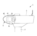
- reference numeral 2 in the drawing is a tower, 3 is a nacelle, 4 is a rotor head, and wind turbine blades attached to the rotor head 4 are omitted.
- the rotor head 4 of the wind turbine generator 1 is configured such that a resin head cover 42 covers the periphery of a rotor head main body 41 that is a cast component, and the hub control panel 20 and the main shaft are disposed inside the rotor head main body 41.
- In-head devices such as the receiver 10 are installed. Such an in-head device generates heat as the wind power generator 1 is operated, and therefore, exhaust heat is generated from the in-head device inside the rotor head 4.
- the above-mentioned device in the head needs to be protected from moisture and salt according to the installation environment of the wind turbine generator 1. For this reason, the structure of the rotor head main body 41 is hermetically sealed against the outside air, and the exhaust heat of the devices in the head such as the hub control panel 20 is likely to stay inside.
- heat generating devices the devices that generate heat
- centrifugal force acts by the rotation of the rotor head 4, and therefore, in the interior of the rotor head body 41, as shown in FIG.
- a temperature distribution is formed so that the exhaust heat of the device is accumulated and becomes high temperature in a high temperature region Th) surrounded by. That is, a temperature distribution is formed inside the rotor head main body 41 and the head cover 42 so that the temperature decreases from the central portion near the rotation axis toward the outer peripheral surface of the head cover 42.
- the exhaust heat of the in-head device generated during the operation of the wind power generator 1 has a small temperature difference between the outer surface temperature of the rotor head body 41 and the outer surface temperature of the rotor head cover 42 and the outside air temperature. It is difficult to efficiently dissipate heat from the atmosphere to the outside air. Therefore, the heat inside the rotor head main body 41 is likely to be trapped without being radiated to the outside air, and the temperature of the high temperature region Th tends to rise further to a high temperature. From such a background, in wind power generators, countermeasures for exhaust heat of the devices in the rotor head are desired.
- the present invention has been made in view of the above circumstances, and an object of the present invention is to provide a wind turbine generator that is provided with measures against exhaust heat of the devices in the rotor head.
- the present invention employs the following means.
- a rotor head that receives wind power from a windmill blade rotates a generator installed inside the nacelle to generate electric power, and the upper end of the tower in which the nacelle is erected on the foundation
- a ventilation fan that forms an air flow inside and outside the case is provided in the case of the heat generating device.
- the ventilation fan for forming the air flow inside and outside the casing is provided in the casing of the heat generating device, the exhaust heat accumulated in the casing of the heating device is ventilated.
- the internal temperature of the heat generating device can be kept low, and an air flow that agitates the inside of the rotor head body that is a sealed space is generated.
- the air temperature inside the rotor head body 41 can be leveled, and heat exchange inside and outside the rotor head body 41 can be further promoted.
- the ventilation fan is preferably arranged so as to form an air flow passing through a central portion of the rotor head body.
- a particularly heavy heating device such as a control panel is disposed near the axis of the rotor head in order to prevent eccentricity of the rotation shaft of the rotor head.
- the ventilation fan may be installed on at least one surface of the housing surface with respect to both surfaces of the rotor head in the rotation axis direction. That is, the ventilation fan installation surface of the housing is one surface that becomes the rotor head tip side in the rotation axis direction, one surface that becomes the main bearing side (nacelle side) in the rotation axis direction, or the rotor head tip side and the main shaft in the rotation axis direction. Any of both sides which become a receiving side may be sufficient.
- the ventilation fan may be a fan that blows air inside the casing of the heat generating device toward the center of the rotor head, or air inside the casing of the heat generating device on the nacelle side surface of the inner wall of the rotor head body. It is possible to use a fan that blows air toward it.
- the ventilation fan is an exhaust fan that causes the air inside the casing to flow out of the casing, and a pressure loss element is attached to an intake port of the casing.
- the pressure loss element in this case means a louver, a dust removal filter, a salt removal filter, and the like.
- exhaust heat accumulated in a heat generating device such as a control panel is ventilated to take measures against exhaust heat to keep the temperature inside the heat generating device low, and the temperature determined for the electrical components constituting the heat generating device. A high-temperature atmosphere exceeding the upper limit of the condition is prevented, and stable continuation is guaranteed.
- exhaust heat countermeasures for ventilating exhaust heat in the heat generating device to promote heat dissipation the air inside the rotor head main body is agitated and the temperature distribution is eliminated. For this reason, the temperature difference between the inside of the rotor head body and the outside of the rotor head body is increased, and heat dissipation from the rotor head body is promoted. That is, the exhaust heat in the rotor head main body is efficiently radiated to the outside, and the atmosphere in the rotor head main body is maintained at a predetermined temperature or less, so that stable operation of the heat generating device can be continued.
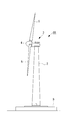
- the wind turbine generator 1 ⁇ / b> A includes a windmill tower (hereinafter referred to as “tower”) 2 erected on the foundation B, a nacelle 3 installed at the upper end of the tower 2, and a substantially horizontal position. And a rotor head 4 provided on the front end side of the nacelle 3 so as to be rotatable around a horizontal rotational axis.
- tower windmill tower
- nacelle 3 installed at the upper end of the tower 2
- a substantially horizontal position a rotor head 4 provided on the front end side of the nacelle 3 so as to be rotatable around a horizontal rotational axis.
- a plurality of (for example, three) wind turbine blades 5 are attached to the rotor head 4 in a radial pattern around its rotational axis.
- An anemometer that measures the peripheral wind speed value, an anemometer that measures the wind direction, and the like are installed at appropriate positions (for example, the upper part) of the outer surface of the nacelle 3.
- the rotor head 4 that receives wind power from the wind turbine blades 5 and rotates around a substantially horizontal rotation axis drives a generator (not shown) installed in the nacelle 3 to generate power.
- the nacelle 3 is installed at the upper end of the tower 2 erected on the foundation B so that the yaw can be turned.
- the tower 2 shown in the figure is a steel monopole type, and a cylindrical tower having a required length (height) is secured by connecting a plurality of tower section flanges (not shown).
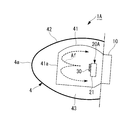
- the rotor head 4 of the wind power generator 1A described above includes, for example, a rotor head main body 41 and a head cover 42 as shown in FIG. 1A.
- the normal rotor head main body 41 is a cast part, and the outer periphery of the rotor head 41 is covered with a resin head cover 42 so as to form a space 43 around the rotor head main body 41.
- a hub control panel 20A for controlling the pitch of the wind turbine blades 5 by hydraulic pressure electrical equipment such as a control panel constituted by a large number of electrical components, and for example, a main bearing 10
- In-head devices such as drive system parts having sliding portions are installed.
- Such an in-head device is a heat generating device that generates heat as the wind power generator 1A is operated, and needs to be protected from moisture and salt according to the installation environment of the wind power generator 1. For this reason, the rotor head main body 41 has a sealed structure against the outside air.
- the control panel of the in-head device such as the hub control panel 20A is provided with a ventilation fan 30 that forms a flow in the internal air of the casing 21.
- a ventilation fan 30 is attached to one surface of a casing 21 having a rectangular parallelepiped shape.
- the pressure loss element 23 is attached to the inlet port 22 opened to the same housing
- the ventilation fan 30 is an exhaust fan that sucks out air in the housing 21 and causes the air inside the housing, whose temperature has been raised by exhaust heat, to flow out of the housing 21 (inside the rotor head body 41 of the rotor head 4).
- the operation of the ventilation fan 30 introduces the head internal air of the rotor head main body 41 into the housing 21 from the intake port 22, so that the hot internal air in the housing is relatively cool. And be ventilated.
- the ventilation fan 30 in this case is installed on the surface of the casing 21 (the surface on the left side in FIG. 1A) on the rotor head tip 4a side in the rotation axis direction of the rotor head 4.
- the casing 21 of the hub control panel 20A includes the ventilation fan 30 that forms a flow in the air inside the casing, the exhaust heat accumulated in the control panel is ventilated.
- the internal temperature can be kept low. Since the inside of the housing 21 of the hub control panel 20A is prevented from having a high temperature atmosphere exceeding the upper limit of the temperature condition defined for the component parts such as electric parts, the hub control panel 20A can continue stable operation. It becomes like this. Further, the air flow discharged out of the casing 21 agitates the interior of the rotor head main body 41. As a result, the air temperature inside the rotor head main body 41 can be leveled. There is no need to install a separate fan for each application, which is advantageous in terms of cost and installation space.
- the ventilation fan 30 of the wind power generator 1 ⁇ / b> A described above is preferably arranged so as to form an air flow passing through the central portion of the rotor head main body 41.
- a heavy heat generating device such as a control panel is disposed near the axis of the rotor head in order to prevent eccentricity of the rotation axis of the rotor head.
- FIG. 1A if the hub control panel 20A is installed on the nacelle 3 side of the rotor head main body 41 and positioned so that the rotational axis center of the ventilation fan 30 substantially coincides with the rotational axis center of the rotor head 4.
- the flow of air flowing out from the inside of the casing 21 passes through the central portion of the rotor head main body 41.
- the ventilation fan 30 installed in this way forms a circulating flow of the head internal air (broken arrow Af in the figure) in the rotor head body 41 of the rotor head 4.
- This circulating flow first flows from the nacelle 3 side toward the rotor head front end 4a side in the axial center portion in the rotor head 41, but the direction is changed by the flow path being blocked by the front end surface 41a of the rotor head body 41 Then, it is folded along the inner wall surface of the rotor head main body 41.
- the circulating flow in the rotor head main body 41 finally returns to the rear end side of the rotor head main body 41, so that the internal air of the rotor head main body 41 is effectively stirred and formed in the rotor head main body 41.
- the distributed temperature distribution is eliminated and the temperature becomes substantially uniform.
- the centrifugal force generated by the rotation of the rotor head 4 acts on the interior of the rotor head body 41 and high temperature air tends to collect in the center, the high temperature air is collected by the ventilation fan 30 of the hub control panel 20A.
- the air flow (wind) of the exhaust is directly applied and stirred, a higher stirring effect can be obtained and the temperature distribution can be made uniform.
- the wall surface temperature of the rotor head main body 41 also rises, and the outer surface temperature of the rotor head main body 41 and the space 43 The temperature difference from the inside also increases. Further, since the air temperature in the space 43 is substantially the same as the temperature of the outside air outside the head cover 42, the temperature difference between the temperature of the air inside the head and the outer surface temperature of the rotor head body 41 and the outside air also increases. .
- the air temperature inside the housing of the hub control panel 20A ventilated by the ventilation fan 30 can be ventilated with cooler air. Therefore, it becomes easy to maintain the air inside the housing at a predetermined temperature or less, and the continuation of the operation of the hub control panel 20A becomes even more stable. Further, since the air flow along the inner wall surface of the rotor head body 41 increases the flow velocity (surface flow velocity) of the air flow flowing along the inner wall surface of the rotor head body 41, the heat transfer performance is improved as the surface flow velocity increases. Also, the cooling of the air inside the head can be promoted.
- the temperature distribution of the air inside the head is made uniform, so that the rotor An exhaust heat countermeasure that increases the temperature difference between the inner wall surface of the head main body 41 and the outside air and increases the heat exchange amount inside and outside the rotor head main body 41 can also be obtained.
- the temperature inside the casing is prevented from increasing, and the hub control panel 20A installed in the rotor head 4 can be stably operated.
- the wind power generator 1B of this embodiment differs in the position of the ventilation fan 30 installed in the hub control panel 20B in the rotor head body 41. That is, the ventilation fan 30 is installed on the surface that is on the main bearing 10 side (nacelle 3 side) in the rotation axis direction with respect to the casing 21 of the hub control panel 20B.
- the position of the ventilation fan 30 is arrange
- the air flow in the direction of the rotation axis in the present embodiment is opposite to that in the above-described embodiment, and the flow toward the main bearing 10 side is the main flow as indicated by the broken line arrow Af in the figure.
- the ventilation fan 30 in this case also employs an exhaust fan similar to the above-described embodiment. The air flow from the ventilation fan 30 installed in this way changes its direction by being blocked by the inner wall of the rotor head 41 on the main bearing 10 side, and is turned back along the inner wall surface of the rotor head body 41. Then, a circulating flow passes from the tip of the rotor head body 41 to the center of the rotor head body 41.
- the above-described circulating flow causes the head to flow. Since the internal air is agitated efficiently and the temperature distribution is made uniform, it is possible to obtain a countermeasure against exhaust heat that increases the amount of heat exchange inside and outside the rotor head body 41. As a result, the temperature inside the casing is prevented from increasing, and the hub control panel 20B installed in the rotor head 4 can be stably operated.
- symbol is attached
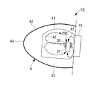
- the number of ventilation fans 30 installed on the hub control panel 20C in the rotor head body 41 is different. That is, the ventilation fan 30 is provided on both the surface on the rotor head tip 4a side in the rotation axis direction and the surface on the main bearing 10 side (nacelle 3 side) in the rotation axis direction with respect to the casing 21 of the hub control panel 20C. is set up.
- the position of the ventilation fan 30 is preferably arranged so as to form an air flow in the rotation axis direction inside the rotor head main body 41 as in the above-described embodiment.
- the air flow in the direction of the rotation axis in the present embodiment is in the same direction as in the first embodiment, and the flow toward the rotor head tip 4a side is the mainstream as indicated by a broken line arrow Af in the drawing.
- the ventilation fan 30 in this case also employs an exhaust fan similar to the above-described embodiment.
- the circulating flow of air inside the head Since the temperature distribution of the air is made uniform, it is possible to obtain a measure for exhaust heat that increases the amount of heat exchange inside and outside the rotor head body 41. As a result, the temperature inside the casing is prevented from increasing, and the hub control panel 20C installed in the rotor head 4 can be stably operated.
- the position of the intake port is not particularly limited, and one or a plurality of intake positions may be provided at appropriate positions of the housing 21.
- the ventilation fan 30 of the present embodiment may be installed on at least one surface with respect to both surfaces of the casing 21 in the rotation axis direction. That is, the installation surface of the ventilation fan 30 in the casing 21 is one surface that is the rotor head tip 4a side in the rotation axis direction, one surface that is the main bearing 10 side in the rotation axis direction, or the rotor head tip 4a side in the rotation axis direction. And either of both surfaces which become the main bearing 10 side may be sufficient.
- the ventilation fan of embodiment mentioned above was made into the exhaust fan which discharges
- a suction fan may be employed.
- this invention is not limited to embodiment mentioned above, In the range which does not deviate from the summary, it can change suitably.
- Wind turbine generator 1A to 1C Wind turbine generator 2 Tower 3 Nacelle 4 Rotor head 4a Tip of rotor head 5 Wind turbine blade 10 Main bearing 20A to 20C Hub control panel (control panel) 21 Housing 22 Inlet 23 Pressure Loss Element 30 Ventilation Fan 41 Rotor Head Body 42 Head Cover
Landscapes
- Engineering & Computer Science (AREA)
- Life Sciences & Earth Sciences (AREA)
- Sustainable Development (AREA)
- Sustainable Energy (AREA)
- Chemical & Material Sciences (AREA)
- Combustion & Propulsion (AREA)
- Mechanical Engineering (AREA)
- General Engineering & Computer Science (AREA)
- Wind Motors (AREA)
- Motor Or Generator Cooling System (AREA)
- Structures Of Non-Positive Displacement Pumps (AREA)
Abstract
ロータヘッド内機器の排熱対策を施した風力発電装置を提供する。風車翼に風力を受けて回転するロータヘッド(4)がナセルの内部に設置された発電機を駆動して発電し、ナセルが基礎上に立設されたタワーの上端部に設置されるとともに、ロータヘッド(4)の内部にハブ制御盤(20A)が設置されている風力発電装置(1A)において、ハブ制御盤(20A)の筐体(21)に、筐体(21)内外に流れを形成する換気ファン(30)を設けた。
Description
本発明は、ロータヘッドの内部に設置される制御盤内の雰囲気を良好に保つ風力発電装置に関する。
風力発電装置(以下では「風車」とも呼ぶ)は、風車翼を備えたロータヘッドが風力を受けて回転し、この回転を増速機により増速するなどして駆動される発電機により発電する装置である。
上述したロータヘッドは、風車用タワー(以下、「タワー」と呼ぶ)上に設置されてヨー旋回可能なナセルの端部に取り付けられ、略水平な横方向の回転軸線周りに回転可能となるように支持されている。
上述したロータヘッドは、風車用タワー(以下、「タワー」と呼ぶ)上に設置されてヨー旋回可能なナセルの端部に取り付けられ、略水平な横方向の回転軸線周りに回転可能となるように支持されている。
図5に示す従来の風力発電装置1において、図中の符号2はタワー、3はナセル、4はロータヘッドであり、ロータヘッド4に取り付けられる風車翼は省略されている。
風力発電装置1のロータヘッド4は、鋳造部品であるロータヘッド本体41の周囲を樹脂製のヘッドカバー42が覆うように構成されており、ロータヘッド本体41の内部には、ハブ制御盤20や主軸受け10等のヘッド内機器が設置されている。このようなヘッド内機器は、風力発電装置1の運転に伴って発熱するので、ロータヘッド4の内部にはヘッド内機器から排熱が発生することとなる。
風力発電装置1のロータヘッド4は、鋳造部品であるロータヘッド本体41の周囲を樹脂製のヘッドカバー42が覆うように構成されており、ロータヘッド本体41の内部には、ハブ制御盤20や主軸受け10等のヘッド内機器が設置されている。このようなヘッド内機器は、風力発電装置1の運転に伴って発熱するので、ロータヘッド4の内部にはヘッド内機器から排熱が発生することとなる。
一方、上述したヘッド内機器は、風力発電装置1の設置環境に応じて湿気や塩分から保護する必要がある。このため、ロータヘッド本体41の構造は外気に対して密閉されており、ハブ制御盤20等のヘッド内機器の排熱が内部にこもりやすい構造となっている。
たとえばハブ制御盤20のような電気制御機器類は、構成する電気部品等に定められた温度条件の上限から、所定値以上の高温雰囲気では安定した動作が保証されず、従って、風力発電装置1の運転継続に支承をきたすことが懸念される。すなわち、ハブ制御盤20の内部温度が所定位置以上の高温になると、風力発電装置1の安定した運転継続は困難になる。
上述したロータヘッド内の内部機器を冷却する技術としては、たとえばロータヘッドの先端部に空気取入口を設けることが提案されている。(たとえば、特許文献1参照)
上述したロータヘッド内の内部機器を冷却する技術としては、たとえばロータヘッドの先端部に空気取入口を設けることが提案されている。(たとえば、特許文献1参照)
上述したように、風力発電装置1のロータヘッド本体41内を密閉空間とする場合、内部に発熱する機器類(以下、「発熱機器」という)が設置されているため、内部温度の上昇が、安定した運転継続の障害となっている。
しかも、風力発電装置1の運転中は、ロータヘッド4の回転により遠心力が作用するので、ロータヘッド本体41の内部においては、図5に示すように、回転軸に近い中心部の領域(破線で囲まれた高温領域Th)に機器排熱がこもって高温となるような温度分布を形成する。すなわち、ロータヘッド本体41及びヘッドカバー42の内部には、回転軸に近い中心部からヘッドカバー42の外周面方向へ温度低下するように温度分布が形成されている。
しかも、風力発電装置1の運転中は、ロータヘッド4の回転により遠心力が作用するので、ロータヘッド本体41の内部においては、図5に示すように、回転軸に近い中心部の領域(破線で囲まれた高温領域Th)に機器排熱がこもって高温となるような温度分布を形成する。すなわち、ロータヘッド本体41及びヘッドカバー42の内部には、回転軸に近い中心部からヘッドカバー42の外周面方向へ温度低下するように温度分布が形成されている。
このため、風力発電装置1の運転中に生じるヘッド内機器の排熱は、ロータヘッド本体41の外表面温度及びロータヘッドカバー42の外表面温度と外気温度との温度差が小さいため、ロータヘッド4から外気へ効率よく放熱されにくい状況にある。従って、ロータヘッド本体41の内部は、排熱が外気へ放熱されずにこもりやすくなり、高温領域Thの温度はさらに温度上昇して高温となる傾向にある。このような背景から、風力発電装置においては、ロータヘッド内機器の排熱対策が望まれている。
本発明は、上記の事情に鑑みてなされたものであり、その目的とするところは、ロータヘッド内機器の排熱対策を施した風力発電装置を提供することにある。
本発明は、上記の事情に鑑みてなされたものであり、その目的とするところは、ロータヘッド内機器の排熱対策を施した風力発電装置を提供することにある。
本発明は、上記の課題を解決するため、下記の手段を採用した。
本発明に係る風力発電装置は、風車翼に風力を受けて回転するロータヘッドがナセルの内部に設置された発電機を駆動して発電し、前記ナセルが基礎上に立設されたタワーの上端部に設置されるとともに、前記ロータヘッドの内部に発熱機器が設置されている風力発電装置において、前記発熱機器の筐体に、該筐体の内外に空気の流れを形成する換気ファンを設けた。
本発明に係る風力発電装置は、風車翼に風力を受けて回転するロータヘッドがナセルの内部に設置された発電機を駆動して発電し、前記ナセルが基礎上に立設されたタワーの上端部に設置されるとともに、前記ロータヘッドの内部に発熱機器が設置されている風力発電装置において、前記発熱機器の筐体に、該筐体の内外に空気の流れを形成する換気ファンを設けた。
このような風力発電装置によれば、前記発熱機器の筐体に、該筐体の内外に空気の流れを形成する換気ファンを設けたので、発熱機器の筐体内にこもった排熱を換気して発熱機器内部温度を低く保つことができるとともに、密閉空間であるロータヘッド本体内を攪拌する空気流れが生成される。このため、ロータヘッド本体41内部の空気温度を平準化することができ、さらに、ロータヘッド本体41内外の熱交換を促進させることができる。それぞれの用途に別個にファンを設置する必要が無く、コスト的にも、配置スペース的にも有利である。
上記の風力発電装置において、前記換気ファンは、前記ロータヘッド本体の中心部を通る空気流を形成するように配置されていることが好ましい。これにより、回転軸心近辺の高温の空気が攪拌されやすくなり、ロータヘッドの内部に形成されていた空気の温度分布を解消して略均一化することができる。
上記の発明において、特に制御盤のような重量のある発熱機器は、前記ロータヘッドの回転軸の偏芯を防ぐために、前記ロータヘッドの軸心近傍に配置されていることが好ましい。
上記の発明において、特に制御盤のような重量のある発熱機器は、前記ロータヘッドの回転軸の偏芯を防ぐために、前記ロータヘッドの軸心近傍に配置されていることが好ましい。
上記の発明において、前記換気ファンは、前記筐体表面のロータヘッドの回転軸方向両面に対し、少なくとも一方の面に設置されていればよい。すなわち、筐体の換気ファン設置面は、回転軸方向のロータヘッド先端側となる一面、回転軸方向の主軸受け側(ナセル側)となる一面、あるいは、回転軸方向のロータヘッド先端側及び主軸受け側となる両面のいずれであってもよい。
また、前記換気ファンには、前記発熱機器の筐体内部空気を前記ロータヘッドの中心部に向けて送風するファン、あるいは、前記発熱機器の筐体内部空気を前記ロータヘッド本体内壁のナセル側面に向けて送風するファンの使用が可能である。
上記の発明において、前記換気ファンは、前記筐体内部空気を前記筐体外へ流出させる排気ファンとされ、前記筐体の吸気口に圧損要素を取り付けることが好ましい。これにより、発熱機器の内部に雨水等の異物が侵入することを防止または抑制できる。
この場合の圧損要素は、ガラリ、除塵フィルタ及び除塩フィルタ等を意味している。
この場合の圧損要素は、ガラリ、除塵フィルタ及び除塩フィルタ等を意味している。
上述した本発明によれば、制御盤等の発熱機器内にこもった排熱を換気して発熱機器内部温度を低く保つ排熱対策を施し、発熱機器を構成する電気部品等に定められた温度条件の上限を超える高温の雰囲気になることを防止し、安定した動作の継続が保証されるようになる。
また、発熱機器内の排熱を換気して放熱を促進する排熱対策に加えて、ロータヘッド本体内部空気が攪拌され温度分布が解消される。このため、ロータヘッド本体内部とロータヘッド本体外との温度差が大きくなり、ロータヘッド本体からの放熱が促進される。すなわち、ロータヘッド本体内の排熱を効率よく外部へ放熱し、ロータヘッド本体内の雰囲気を所定温度以下に維持することで、発熱機器の安定した運転継続が可能になる。
また、発熱機器内の排熱を換気して放熱を促進する排熱対策に加えて、ロータヘッド本体内部空気が攪拌され温度分布が解消される。このため、ロータヘッド本体内部とロータヘッド本体外との温度差が大きくなり、ロータヘッド本体からの放熱が促進される。すなわち、ロータヘッド本体内の排熱を効率よく外部へ放熱し、ロータヘッド本体内の雰囲気を所定温度以下に維持することで、発熱機器の安定した運転継続が可能になる。
以下、本発明に係る風力発電装置の一実施形態を図面に基づいて説明する。
図2に示すように、風力発電装置1Aは、基礎B上に立設される風車用タワー(以下では「タワー」と呼ぶ)2と、タワー2の上端に設置されるナセル3と、略水平な横方向の回転軸線周りに回転可能に支持されてナセル3の前端部側に設けられるロータヘッド4とを有している。
図2に示すように、風力発電装置1Aは、基礎B上に立設される風車用タワー(以下では「タワー」と呼ぶ)2と、タワー2の上端に設置されるナセル3と、略水平な横方向の回転軸線周りに回転可能に支持されてナセル3の前端部側に設けられるロータヘッド4とを有している。
ロータヘッド4には、その回転軸線周りに放射状にして複数枚(たとえば3枚)の風車翼5が取り付けられている。これにより、ロータヘッド4の回転軸線方向から風車翼5に当たった風の力が、ロータヘッド4を回転軸線周りに回転させる動力に変換されるようになっている。
ナセル3の外周面適所(たとえば上部等)には、周辺の風速値を測定する風速計や、風向を測定する風向計等が設置されている。
ナセル3の外周面適所(たとえば上部等)には、周辺の風速値を測定する風速計や、風向を測定する風向計等が設置されている。
すなわち、風力発電装置1Aは、風車翼5に風力を受けて略水平な回転軸線周りに回転するロータヘッド4がナセル3の内部に設置された発電機(不図示)を駆動して発電するとともに、ナセル3が基礎B上に立設されたタワー2の上端部に設置されてヨー旋回可能となっている。
なお、図示のタワー2は鋼製のモノポール式とされ、複数に分割したタワーセクションのフランジ(不図示)を接続することにより、必要な長さ(高さ)を確保した円筒タワーとなる。
なお、図示のタワー2は鋼製のモノポール式とされ、複数に分割したタワーセクションのフランジ(不図示)を接続することにより、必要な長さ(高さ)を確保した円筒タワーとなる。
<第1の実施形態>
上述した風力発電装置1Aのロータヘッド4は、たとえば図1Aに示すように、ロータヘッド本体41とヘッドカバー42とを具備して構成される。通常のロータヘッド本体41は鋳造部品であり、ロータヘッド本体41の周囲に空間部43を形成するようにして、ロータヘッド41の外周が樹脂製のヘッドカバー42により覆われている。
ロータヘッド4の内部には、たとえば風車翼5を油圧によりピッチ制御するハブ制御盤20Aのように、多数の電気部品により構成される制御盤等の電気機器類や、たとえば主軸受け10のように、摺動部を有する駆動系部品等のヘッド内機器が設置されている。このようなヘッド内機器は、風力発電装置1Aの運転に伴って発熱する発熱機器であり、風力発電装置1の設置環境に応じて湿気や塩分から保護する必要がある。このため、ロータヘッド本体41は外気に対して密閉構造となっている。
上述した風力発電装置1Aのロータヘッド4は、たとえば図1Aに示すように、ロータヘッド本体41とヘッドカバー42とを具備して構成される。通常のロータヘッド本体41は鋳造部品であり、ロータヘッド本体41の周囲に空間部43を形成するようにして、ロータヘッド41の外周が樹脂製のヘッドカバー42により覆われている。
ロータヘッド4の内部には、たとえば風車翼5を油圧によりピッチ制御するハブ制御盤20Aのように、多数の電気部品により構成される制御盤等の電気機器類や、たとえば主軸受け10のように、摺動部を有する駆動系部品等のヘッド内機器が設置されている。このようなヘッド内機器は、風力発電装置1Aの運転に伴って発熱する発熱機器であり、風力発電装置1の設置環境に応じて湿気や塩分から保護する必要がある。このため、ロータヘッド本体41は外気に対して密閉構造となっている。
このうち、たとえばハブ制御盤20Aのようなヘッド内機器の制御盤には、筐体21の内部空気に流れを形成する換気ファン30が設けられている。図示の構成例では、直方体形状とした筐体21の一面に換気ファン30が取り付けられている。また、換気ファンと同じ筐体面に開口する吸気口22には、圧損要素23が取り付けられている。この圧損要素23は、雨や埃等の異物がハブ制御盤20A内に侵入することを防止するもので、たとえばガラリや除塵及び除塩用のフィルタが有効である。
換気ファン30は、筐体21内の空気を吸い出す排気ファンであり、排熱により温度上昇した筐体内部空気を筐体21外(ロータヘッド4のロータヘッド本体41内)へ流出させる。一方、換気ファン30の動作により、筐体21の内部には吸気口22からロータヘッド本体41のヘッド内部空気が導入されることにより、高温の筐体内部空気は相対的に低温のヘッド内部空気と換気される。
また、この場合の換気ファン30は、ロータヘッド4の回転軸方向においてロータヘッド先端4a側となる筐体21の面(図1Aの紙面左側の面)に設置されている。
また、この場合の換気ファン30は、ロータヘッド4の回転軸方向においてロータヘッド先端4a側となる筐体21の面(図1Aの紙面左側の面)に設置されている。
このような風力発電装置1Aによれば、ハブ制御盤20Aの筐体21が、筐体内部空気に流れを形成する換気ファン30を備えているので、制御盤内にこもった排熱を換気して内部温度を低く保つことができる。ハブ制御盤20Aの筐体21内は、電気部品等の構成部品に定められた温度条件の上限を超える高温の雰囲気になることが防止されるので、ハブ制御盤20Aは安定した動作を継続できるようになる。
また、筐体21外に排出された空気流れがロータヘッド本体41内部を攪拌することとなり、この結果、ロータヘッド本体41内部の空気温度を平準化することができる。夫々の用途に別個にファンを設置する必要が無くコスト的にも、配置スペース的にも有利である。
また、筐体21外に排出された空気流れがロータヘッド本体41内部を攪拌することとなり、この結果、ロータヘッド本体41内部の空気温度を平準化することができる。夫々の用途に別個にファンを設置する必要が無くコスト的にも、配置スペース的にも有利である。
上述した風力発電装置1Aの換気ファン30は、前記ロータヘッド本体41の中心部を通る空気流を形成するように配置されていることが好ましい。
また、上記の発明において、特に制御盤のような重量のある発熱機器は、前記ロータヘッドの回転軸の偏芯を防ぐ為に前記ロータヘッドの軸心近傍に配置されていることが好ましい。たとえば、図1Aの態様のようにハブ制御盤20Aをロータヘッド本体41のナセル3側に設置し、換気ファン30の回転軸中心がロータヘッド4の回転軸中心と略一致するように位置決めすれば、筐体21内から流出する空気の流れは、ロータヘッド本体41の中心部を通る。
また、上記の発明において、特に制御盤のような重量のある発熱機器は、前記ロータヘッドの回転軸の偏芯を防ぐ為に前記ロータヘッドの軸心近傍に配置されていることが好ましい。たとえば、図1Aの態様のようにハブ制御盤20Aをロータヘッド本体41のナセル3側に設置し、換気ファン30の回転軸中心がロータヘッド4の回転軸中心と略一致するように位置決めすれば、筐体21内から流出する空気の流れは、ロータヘッド本体41の中心部を通る。
このように設置されている換気ファン30は、ロータヘッド4のロータヘッド本体41内に、ヘッド内部空気の循環流(図中の破線矢印Af)を形成する。この循環流は、最初にロータヘッド41内の軸中心部をナセル3側からロータヘッド先端4a側へ向かう流れとなるが、ロータヘッド本体41の先端面41aに流路を遮られることにより方向転換して、ロータヘッド本体41の内壁面に沿って折り返すことになる。
この結果、ロータヘッド本体41内の循環流は、最終的にロータヘッド本体41の後端側へ戻るので、ロータヘッド本体41の内部空気は効果的に撹拌され、ロータヘッド本体41内に形成されていた温度分布が解消されて略均一化する。
また、ロータヘッド本体41の内部は、ロータヘッド4の回転による遠心力が作用して高温の空気が中心部に集まりやすいことから、ハブ制御盤20Aの換気ファン30により高温空気が集まった部分に排気の空気流(風)を直接当てて撹拌するようにした本実施形態は、さらに高い撹拌効果を得て温度分布を均一化することができる。
また、ロータヘッド本体41の内部は、ロータヘッド4の回転による遠心力が作用して高温の空気が中心部に集まりやすいことから、ハブ制御盤20Aの換気ファン30により高温空気が集まった部分に排気の空気流(風)を直接当てて撹拌するようにした本実施形態は、さらに高い撹拌効果を得て温度分布を均一化することができる。
このような循環流の形成により、ロータヘッド本体41内部空気が撹拌されて温度分布が解消されると、ロータヘッド本体41の壁面温度も上昇し、ロータヘッド本体41の外表面温度と空間部43内との温度差も大きくなる。
また、空間部43内の空気温度は、ヘッドカバー42の外側となる外気の温度と略同じになるため、ヘッド内部空気の温度及びロータヘッド本体41の外表面温度と外気との温度差も大きくなる。
この結果、高温側のロータヘッド41から低温側の外気へ向けた放熱が促進されるようになり、ロータヘッド4内の排熱も効率よく外部へ放熱されることで、ロータヘッド4のヘッド内部空気温度が低下する。
また、空間部43内の空気温度は、ヘッドカバー42の外側となる外気の温度と略同じになるため、ヘッド内部空気の温度及びロータヘッド本体41の外表面温度と外気との温度差も大きくなる。
この結果、高温側のロータヘッド41から低温側の外気へ向けた放熱が促進されるようになり、ロータヘッド4内の排熱も効率よく外部へ放熱されることで、ロータヘッド4のヘッド内部空気温度が低下する。
すなわち、ロータヘッド4においては、ロータヘッド本体41の内部空気温度が低下するので、換気ファン30により換気されるハブ制御盤20Aの筐体内部空気温度をより低温の空気で換気できるようになる。従って、筐体内部空気を所定温度以下に維持することが容易になり、ハブ制御盤20Aの運転継続はより一層安定したものとなる。
また、ロータヘッド本体41の内壁面に沿った空気流は、ロータヘッド本体41の内壁面に沿って流れる空気流の流速(表面流速)を増すので、表面流速の増大に伴う伝熱性能の向上によってもヘッド内部空気の冷却を促進することができる。
また、ロータヘッド本体41の内壁面に沿った空気流は、ロータヘッド本体41の内壁面に沿って流れる空気流の流速(表面流速)を増すので、表面流速の増大に伴う伝熱性能の向上によってもヘッド内部空気の冷却を促進することができる。
このように、上述した本実施形態によれば、ハブ制御盤20A内の排熱を換気して放熱を促進する排熱対策に加えて、ヘッド内部空気の温度分布を均一化することで、ロータヘッド本体41の内壁表面と外気との温度差を増し、ロータヘッド本体41の内外における熱交換量を増加させる排熱対策も得られる。この結果、筐体内部温度の上昇が防止されて、ロータヘッド4内に設置されたハブ制御盤20Aの安定した運転を可能にする。
<第2の実施形態>
次に、本発明に係る風力発電装置の第2の実施形態を図3に基づいて説明する。なお、上述した実施形態と同様の部分には同じ符号を付し、その詳細な説明は省略する。
この実施形態の風力発電装置1Bは、ロータヘッド本体41内のハブ制御盤20Bに設置された換気ファン30の位置が異なっている。すなわち、換気ファン30は、ハブ制御盤20Bの筐体21に対し、回転軸方向の主軸受け10側(ナセル3側)となる面に設置されている。
次に、本発明に係る風力発電装置の第2の実施形態を図3に基づいて説明する。なお、上述した実施形態と同様の部分には同じ符号を付し、その詳細な説明は省略する。
この実施形態の風力発電装置1Bは、ロータヘッド本体41内のハブ制御盤20Bに設置された換気ファン30の位置が異なっている。すなわち、換気ファン30は、ハブ制御盤20Bの筐体21に対し、回転軸方向の主軸受け10側(ナセル3側)となる面に設置されている。
また、換気ファン30の位置は、上述した実施形態と同様に、ロータヘッド本体41の内部に、回転軸方向の空気流を形成するように配置されていることが好ましい。但し、本実施形態における回転軸方向の空気流は、上述した実施形態とは逆向きとなり、図中に破線矢印Afで示すように、主軸受け10側に向かう流れが主流となる。なお、この場合の換気ファン30も、上述した実施形態と同様の排気ファンを採用している。
このように設置されている換気ファン30からの空気流れは、ロータヘッド41の主軸受け10側の内壁に流路を遮られることにより方向転換して、ロータヘッド本体41の内壁面に沿って折り返し、ロータヘッド本体41の先端からロータヘッド本体41中心部を通る循環流となる。
このように設置されている換気ファン30からの空気流れは、ロータヘッド41の主軸受け10側の内壁に流路を遮られることにより方向転換して、ロータヘッド本体41の内壁面に沿って折り返し、ロータヘッド本体41の先端からロータヘッド本体41中心部を通る循環流となる。
このような構成を採用しても、上述した第1の実施形態と同様に、ハブ制御盤20B内の排熱を換気して放熱を促進する排熱対策に加えて、上述した循環流がヘッド内部空気を効率よく撹拌して温度分布を均一化するので、ロータヘッド本体41の内外における熱交換量を増加させる排熱対策も得られるようになる。この結果、筐体内部温度の上昇が防止されて、ロータヘッド4内に設置されたハブ制御盤20Bの安定した運転を可能にする。
<第3の実施形態>
次に、本発明に係る風力発電装置の第3の実施形態を図4に基づいて説明する。なお、上述した実施形態と同様の部分には同じ符号を付し、その詳細な説明は省略する。
この実施形態の風力発電装置1Cは、ロータヘッド本体41内のハブ制御盤20Cに設置された換気ファン30の数が異なっている。すなわち、換気ファン30は、ハブ制御盤20Cの筐体21に対し、回転軸方向のロータヘッド先端4a側となる面及び回転軸方向の主軸受け10側(ナセル3側)となる面の両方に設置されている。
次に、本発明に係る風力発電装置の第3の実施形態を図4に基づいて説明する。なお、上述した実施形態と同様の部分には同じ符号を付し、その詳細な説明は省略する。
この実施形態の風力発電装置1Cは、ロータヘッド本体41内のハブ制御盤20Cに設置された換気ファン30の数が異なっている。すなわち、換気ファン30は、ハブ制御盤20Cの筐体21に対し、回転軸方向のロータヘッド先端4a側となる面及び回転軸方向の主軸受け10側(ナセル3側)となる面の両方に設置されている。
また、換気ファン30の位置は、上述した実施形態と同様に、2台ともロータヘッド本体41の内部に、回転軸方向の空気流を形成するように配置されていることが好ましい。本実施形態における回転軸方向の空気流は、第1の実施形態と同様の向きになり、図中に破線矢印Afで示すように、ロータヘッド先端4a側に向かう流れが主流となる。なお、この場合の換気ファン30も、上述した実施形態と同様の排気ファンを採用している
このような構成を採用しても、上述した実施形態と同様に、ハブ制御盤20C内の排熱を換気して放熱を促進する排熱対策に加えて、ヘッド内部空気の循環流がヘッド内部空気の温度分布を均一化するので、ロータヘッド本体41の内外における熱交換量を増加させる排熱対策も得られるようになる。この結果、筐体内部温度の上昇が防止されて、ロータヘッド4内に設置されたハブ制御盤20Cの安定した運転を可能にする。なお、この場合の吸気口位置は特に限定されることはなく、筐体21の適所に1または複数設けておけばよい。
上述したように、本実施形態の換気ファン30は、筐体21の回転軸方向両面に対し、少なくとも一方の面に設置されていればよい。すなわち、筐体21における換気ファン30の設置面は、回転軸方向のロータヘッド先端4a側となる一面、回転軸方向の主軸受け10側となる一面、あるいは、回転軸方向のロータヘッド先端4a側及び主軸受け10側となる両面のいずれでもよい。
また、上述した実施形態の換気ファンは、筐体21内から筐体内部空気を排出する排気ファンとしたが、筐体21内にヘッド内部空気を吸い込んで排気口から筐体内部空気を排出させる吸引ファンを採用してもよい。
なお、本発明は上述した実施形態に限定されることはなく、その要旨を逸脱しない範囲内において適宜変更することができる。
また、上述した実施形態の換気ファンは、筐体21内から筐体内部空気を排出する排気ファンとしたが、筐体21内にヘッド内部空気を吸い込んで排気口から筐体内部空気を排出させる吸引ファンを採用してもよい。
なお、本発明は上述した実施形態に限定されることはなく、その要旨を逸脱しない範囲内において適宜変更することができる。
1A~1C 風力発電装置
2 タワー
3 ナセル
4 ロータヘッド
4a ロータヘッド先端
5 風車翼
10 主軸受け
20A~20C ハブ制御盤(制御盤)
21 筐体
22 吸気口
23 圧損要素
30 換気ファン
41 ロータヘッド本体
42 ヘッドカバー
2 タワー
3 ナセル
4 ロータヘッド
4a ロータヘッド先端
5 風車翼
10 主軸受け
20A~20C ハブ制御盤(制御盤)
21 筐体
22 吸気口
23 圧損要素
30 換気ファン
41 ロータヘッド本体
42 ヘッドカバー
Claims (7)
- 風車翼に風力を受けて回転するロータヘッドがナセルの内部に設置された発電機を駆動して発電し、前記ナセルが基礎上に立設されたタワーの上端部に設置されるとともに、前記ロータヘッドの内部に発熱機器が設置されている風力発電装置において、
前記発熱機器の筐体に、該筐体の内外に空気の流れを形成する換気ファンを設けた風力発電装置。 - 前記換気ファンが、前記ロータヘッド内の中心部を通る空気流を形成するように配置されている請求項1に記載の風力発電装置。
- 前記発熱機器が、前記ロータヘッドの軸心近傍に配置されている請求項1に記載の風力発電装置。
- 前記換気ファンが、前記筐体の回転軸方向両面に対し、少なくとも一方の面に設置されている請求項1に記載の風力発電装置。
- 前記換気ファンが、前記発熱機器の筐体内部空気を前記ロータヘッド内の中心部に向けて送風する請求項1に記載の風力発電装置。
- 前記換気ファンが、前記発熱機器の筐体内部空気を前記ロータヘッド内のナセル側壁面に向けて送風する請求項1に記載の風力発電装置。
- 前記換気ファンが、前記筐体内部空気を前記筐体外へ流出させる排気ファンとされ、前記筐体の吸気口に圧損要素を取り付けた請求項1に記載の風力発電装置。
Priority Applications (2)
| Application Number | Priority Date | Filing Date | Title |
|---|---|---|---|
| CN201280009607.5A CN103380296B (zh) | 2011-02-25 | 2012-02-09 | 风力发电装置 |
| US13/449,554 US8502407B2 (en) | 2011-02-25 | 2012-04-18 | Wind power generating apparatus |
Applications Claiming Priority (2)
| Application Number | Priority Date | Filing Date | Title |
|---|---|---|---|
| JP2011040368A JP5449235B2 (ja) | 2011-02-25 | 2011-02-25 | 風力発電装置 |
| JP2011-040368 | 2011-02-25 |
Related Child Applications (1)
| Application Number | Title | Priority Date | Filing Date |
|---|---|---|---|
| US13/449,554 Continuation US8502407B2 (en) | 2011-02-25 | 2012-04-18 | Wind power generating apparatus |
Publications (1)
| Publication Number | Publication Date |
|---|---|
| WO2012114891A1 true WO2012114891A1 (ja) | 2012-08-30 |
Family
ID=46720676
Family Applications (1)
| Application Number | Title | Priority Date | Filing Date |
|---|---|---|---|
| PCT/JP2012/053015 Ceased WO2012114891A1 (ja) | 2011-02-25 | 2012-02-09 | 風力発電装置 |
Country Status (4)
| Country | Link |
|---|---|
| US (1) | US8502407B2 (ja) |
| JP (1) | JP5449235B2 (ja) |
| CN (1) | CN103380296B (ja) |
| WO (1) | WO2012114891A1 (ja) |
Families Citing this family (3)
| Publication number | Priority date | Publication date | Assignee | Title |
|---|---|---|---|---|
| US9657719B2 (en) | 2014-06-16 | 2017-05-23 | General Electric Company | Ventilation arrangement |
| US20180038351A1 (en) * | 2016-08-05 | 2018-02-08 | Siemens Aktiengesellschaft | Wind turbine with improved cooling |
| CN108843524B (zh) * | 2018-06-22 | 2020-04-10 | 北京金风科创风电设备有限公司 | 用于风力发电机组的散热系统及风力发电机组 |
Citations (4)
| Publication number | Priority date | Publication date | Assignee | Title |
|---|---|---|---|---|
| JPH11178282A (ja) * | 1997-12-12 | 1999-07-02 | Railway Technical Res Inst | 通風冷却式回転電機の鉄粉除去装置 |
| JP2000166177A (ja) * | 1998-11-30 | 2000-06-16 | Toyota Autom Loom Works Ltd | 電動機の冷却装置 |
| JP2001211608A (ja) * | 1999-11-15 | 2001-08-03 | Toshiba Kyaria Kk | 車両用発電機 |
| JP2009091929A (ja) * | 2007-10-05 | 2009-04-30 | Mitsubishi Heavy Ind Ltd | 風力発電装置 |
Family Cites Families (17)
| Publication number | Priority date | Publication date | Assignee | Title |
|---|---|---|---|---|
| JPS53151507U (ja) | 1977-05-06 | 1978-11-29 | ||
| JP2001211808A (ja) | 2000-02-03 | 2001-08-07 | Sanshin Shokai:Kk | 自動噴霧方法及びその装置 |
| US7042109B2 (en) * | 2002-08-30 | 2006-05-09 | Gabrys Christopher W | Wind turbine |
| US7075192B2 (en) * | 2004-04-19 | 2006-07-11 | Northern Power Systems, Inc. | Direct drive wind turbine |
| DE102005034899A1 (de) * | 2005-07-26 | 2007-02-01 | Repower Systems Ag | Windenergieanlage mit Einzelpitcheinrichtungen |
| US7427814B2 (en) * | 2006-03-22 | 2008-09-23 | General Electric Company | Wind turbine generators having wind assisted cooling systems and cooling methods |
| CN101384818B (zh) * | 2006-03-25 | 2012-08-01 | 剪式风能公司 | 用于风轮机的热管理系统 |
| US20080050234A1 (en) * | 2006-05-19 | 2008-02-28 | General Compression, Inc. | Wind turbine system |
| US7594800B2 (en) * | 2006-07-31 | 2009-09-29 | General Electric Company | Ventilation assembly for wind turbine rotor hub |
| DE102006054666B4 (de) * | 2006-11-17 | 2010-01-14 | Repower Systems Ag | Schwingungsdämpfung einer Windenergieanlage |
| US8186940B2 (en) | 2007-09-05 | 2012-05-29 | General Electric Company | Ventilation arrangement |
| US20090094981A1 (en) * | 2007-10-12 | 2009-04-16 | General Electric Company | Wind turbine geothermal heating and cooling system |
| US20090206610A1 (en) * | 2008-02-15 | 2009-08-20 | Negel Martin | Cable guard and method of installation |
| PL2151833T3 (pl) * | 2008-08-07 | 2013-08-30 | Starkstrom Geraetebau Gmbh | Układ transformatorowy |
| IT1391939B1 (it) * | 2008-11-12 | 2012-02-02 | Rolic Invest Sarl | Generatore eolico |
| IT1391770B1 (it) * | 2008-11-13 | 2012-01-27 | Rolic Invest Sarl | Generatore eolico per la generazione di energia elettrica |
| IT1393937B1 (it) * | 2009-04-09 | 2012-05-17 | Rolic Invest Sarl | Aerogeneratore |
-
2011
- 2011-02-25 JP JP2011040368A patent/JP5449235B2/ja active Active
-
2012
- 2012-02-09 CN CN201280009607.5A patent/CN103380296B/zh active Active
- 2012-02-09 WO PCT/JP2012/053015 patent/WO2012114891A1/ja not_active Ceased
- 2012-04-18 US US13/449,554 patent/US8502407B2/en active Active
Patent Citations (4)
| Publication number | Priority date | Publication date | Assignee | Title |
|---|---|---|---|---|
| JPH11178282A (ja) * | 1997-12-12 | 1999-07-02 | Railway Technical Res Inst | 通風冷却式回転電機の鉄粉除去装置 |
| JP2000166177A (ja) * | 1998-11-30 | 2000-06-16 | Toyota Autom Loom Works Ltd | 電動機の冷却装置 |
| JP2001211608A (ja) * | 1999-11-15 | 2001-08-03 | Toshiba Kyaria Kk | 車両用発電機 |
| JP2009091929A (ja) * | 2007-10-05 | 2009-04-30 | Mitsubishi Heavy Ind Ltd | 風力発電装置 |
Also Published As
| Publication number | Publication date |
|---|---|
| JP5449235B2 (ja) | 2014-03-19 |
| US8502407B2 (en) | 2013-08-06 |
| CN103380296A (zh) | 2013-10-30 |
| CN103380296B (zh) | 2016-08-24 |
| US20120256425A1 (en) | 2012-10-11 |
| JP2012177326A (ja) | 2012-09-13 |
Similar Documents
| Publication | Publication Date | Title |
|---|---|---|
| CN101117942B (zh) | 用于风力涡轮机转子毂的通风装置 | |
| JP5550508B2 (ja) | 風力発電装置 | |
| KR101162826B1 (ko) | 풍력 발전 장치 | |
| JP5148517B2 (ja) | 風力発電装置 | |
| JP5211244B2 (ja) | 風力発電装置 | |
| CA2446632C (en) | Cooling device for a wind turbine generator | |
| JP5463218B2 (ja) | 風力発電装置 | |
| JP5002309B2 (ja) | 水平軸風車 | |
| JP5595057B2 (ja) | 風力発電装置 | |
| WO2012002397A1 (ja) | 風力発電装置 | |
| JP2007002773A (ja) | 水平軸風車 | |
| JP6650318B2 (ja) | 風力発電装置 | |
| JP5449235B2 (ja) | 風力発電装置 | |
| JP4814608B2 (ja) | 風車 | |
| JP6368559B2 (ja) | 風力発電装置 | |
| JP2015068243A (ja) | 風力発電設備 |
Legal Events
| Date | Code | Title | Description |
|---|---|---|---|
| 121 | Ep: the epo has been informed by wipo that ep was designated in this application |
Ref document number: 12750228 Country of ref document: EP Kind code of ref document: A1 |
|
| NENP | Non-entry into the national phase |
Ref country code: DE |
|
| 122 | Ep: pct application non-entry in european phase |
Ref document number: 12750228 Country of ref document: EP Kind code of ref document: A1 |