WO2012114805A1 - 光化学反応装置及び光化学反応装置を用いた同位体濃縮方法 - Google Patents
光化学反応装置及び光化学反応装置を用いた同位体濃縮方法 Download PDFInfo
- Publication number
- WO2012114805A1 WO2012114805A1 PCT/JP2012/051319 JP2012051319W WO2012114805A1 WO 2012114805 A1 WO2012114805 A1 WO 2012114805A1 JP 2012051319 W JP2012051319 W JP 2012051319W WO 2012114805 A1 WO2012114805 A1 WO 2012114805A1
- Authority
- WO
- WIPO (PCT)
- Prior art keywords
- container
- photochemical reaction
- reaction device
- light
- metal
- Prior art date
- Legal status (The legal status is an assumption and is not a legal conclusion. Google has not performed a legal analysis and makes no representation as to the accuracy of the status listed.)
- Ceased
Links
Images



Classifications
-
- B—PERFORMING OPERATIONS; TRANSPORTING
- B01—PHYSICAL OR CHEMICAL PROCESSES OR APPARATUS IN GENERAL
- B01J—CHEMICAL OR PHYSICAL PROCESSES, e.g. CATALYSIS OR COLLOID CHEMISTRY; THEIR RELEVANT APPARATUS
- B01J19/00—Chemical, physical or physico-chemical processes in general; Their relevant apparatus
- B01J19/08—Processes employing the direct application of electric or wave energy, or particle radiation; Apparatus therefor
- B01J19/12—Processes employing the direct application of electric or wave energy, or particle radiation; Apparatus therefor employing electromagnetic waves
- B01J19/121—Coherent waves, e.g. laser beams
-
- B—PERFORMING OPERATIONS; TRANSPORTING
- B01—PHYSICAL OR CHEMICAL PROCESSES OR APPARATUS IN GENERAL
- B01D—SEPARATION
- B01D59/00—Separation of different isotopes of the same chemical element
- B01D59/34—Separation by photochemical methods
-
- G—PHYSICS
- G02—OPTICS
- G02B—OPTICAL ELEMENTS, SYSTEMS OR APPARATUS
- G02B5/00—Optical elements other than lenses
- G02B5/08—Mirrors
- G02B5/0808—Mirrors having a single reflecting layer
-
- G—PHYSICS
- G02—OPTICS
- G02B—OPTICAL ELEMENTS, SYSTEMS OR APPARATUS
- G02B5/00—Optical elements other than lenses
- G02B5/08—Mirrors
- G02B5/10—Mirrors with curved faces
-
- B—PERFORMING OPERATIONS; TRANSPORTING
- B01—PHYSICAL OR CHEMICAL PROCESSES OR APPARATUS IN GENERAL
- B01J—CHEMICAL OR PHYSICAL PROCESSES, e.g. CATALYSIS OR COLLOID CHEMISTRY; THEIR RELEVANT APPARATUS
- B01J2219/00—Chemical, physical or physico-chemical processes in general; Their relevant apparatus
- B01J2219/00049—Controlling or regulating processes
- B01J2219/00051—Controlling the temperature
- B01J2219/00074—Controlling the temperature by indirect heating or cooling employing heat exchange fluids
- B01J2219/00087—Controlling the temperature by indirect heating or cooling employing heat exchange fluids with heat exchange elements outside the reactor
- B01J2219/00099—Controlling the temperature by indirect heating or cooling employing heat exchange fluids with heat exchange elements outside the reactor the reactor being immersed in the heat exchange medium
-
- B—PERFORMING OPERATIONS; TRANSPORTING
- B01—PHYSICAL OR CHEMICAL PROCESSES OR APPARATUS IN GENERAL
- B01J—CHEMICAL OR PHYSICAL PROCESSES, e.g. CATALYSIS OR COLLOID CHEMISTRY; THEIR RELEVANT APPARATUS
- B01J2219/00—Chemical, physical or physico-chemical processes in general; Their relevant apparatus
- B01J2219/00049—Controlling or regulating processes
- B01J2219/00051—Controlling the temperature
- B01J2219/00132—Controlling the temperature using electric heating or cooling elements
- B01J2219/00135—Electric resistance heaters
-
- B—PERFORMING OPERATIONS; TRANSPORTING
- B01—PHYSICAL OR CHEMICAL PROCESSES OR APPARATUS IN GENERAL
- B01J—CHEMICAL OR PHYSICAL PROCESSES, e.g. CATALYSIS OR COLLOID CHEMISTRY; THEIR RELEVANT APPARATUS
- B01J2219/00—Chemical, physical or physico-chemical processes in general; Their relevant apparatus
- B01J2219/02—Apparatus characterised by their chemically-resistant properties
- B01J2219/0204—Apparatus characterised by their chemically-resistant properties comprising coatings on the surfaces in direct contact with the reactive components
- B01J2219/0209—Apparatus characterised by their chemically-resistant properties comprising coatings on the surfaces in direct contact with the reactive components of glass
-
- B—PERFORMING OPERATIONS; TRANSPORTING
- B01—PHYSICAL OR CHEMICAL PROCESSES OR APPARATUS IN GENERAL
- B01J—CHEMICAL OR PHYSICAL PROCESSES, e.g. CATALYSIS OR COLLOID CHEMISTRY; THEIR RELEVANT APPARATUS
- B01J2219/00—Chemical, physical or physico-chemical processes in general; Their relevant apparatus
- B01J2219/02—Apparatus characterised by their chemically-resistant properties
- B01J2219/0204—Apparatus characterised by their chemically-resistant properties comprising coatings on the surfaces in direct contact with the reactive components
- B01J2219/0236—Metal based
-
- B—PERFORMING OPERATIONS; TRANSPORTING
- B01—PHYSICAL OR CHEMICAL PROCESSES OR APPARATUS IN GENERAL
- B01J—CHEMICAL OR PHYSICAL PROCESSES, e.g. CATALYSIS OR COLLOID CHEMISTRY; THEIR RELEVANT APPARATUS
- B01J2219/00—Chemical, physical or physico-chemical processes in general; Their relevant apparatus
- B01J2219/02—Apparatus characterised by their chemically-resistant properties
- B01J2219/025—Apparatus characterised by their chemically-resistant properties characterised by the construction materials of the reactor vessel proper
- B01J2219/0254—Glass
-
- B—PERFORMING OPERATIONS; TRANSPORTING
- B01—PHYSICAL OR CHEMICAL PROCESSES OR APPARATUS IN GENERAL
- B01J—CHEMICAL OR PHYSICAL PROCESSES, e.g. CATALYSIS OR COLLOID CHEMISTRY; THEIR RELEVANT APPARATUS
- B01J2219/00—Chemical, physical or physico-chemical processes in general; Their relevant apparatus
- B01J2219/02—Apparatus characterised by their chemically-resistant properties
- B01J2219/025—Apparatus characterised by their chemically-resistant properties characterised by the construction materials of the reactor vessel proper
- B01J2219/0277—Metal based
-
- B—PERFORMING OPERATIONS; TRANSPORTING
- B01—PHYSICAL OR CHEMICAL PROCESSES OR APPARATUS IN GENERAL
- B01J—CHEMICAL OR PHYSICAL PROCESSES, e.g. CATALYSIS OR COLLOID CHEMISTRY; THEIR RELEVANT APPARATUS
- B01J2219/00—Chemical, physical or physico-chemical processes in general; Their relevant apparatus
- B01J2219/08—Processes employing the direct application of electric or wave energy, or particle radiation; Apparatus therefor
- B01J2219/0871—Heating or cooling of the reactor
-
- B—PERFORMING OPERATIONS; TRANSPORTING
- B01—PHYSICAL OR CHEMICAL PROCESSES OR APPARATUS IN GENERAL
- B01J—CHEMICAL OR PHYSICAL PROCESSES, e.g. CATALYSIS OR COLLOID CHEMISTRY; THEIR RELEVANT APPARATUS
- B01J2219/00—Chemical, physical or physico-chemical processes in general; Their relevant apparatus
- B01J2219/08—Processes employing the direct application of electric or wave energy, or particle radiation; Apparatus therefor
- B01J2219/0873—Materials to be treated
- B01J2219/0875—Gas
-
- B—PERFORMING OPERATIONS; TRANSPORTING
- B01—PHYSICAL OR CHEMICAL PROCESSES OR APPARATUS IN GENERAL
- B01J—CHEMICAL OR PHYSICAL PROCESSES, e.g. CATALYSIS OR COLLOID CHEMISTRY; THEIR RELEVANT APPARATUS
- B01J2219/00—Chemical, physical or physico-chemical processes in general; Their relevant apparatus
- B01J2219/08—Processes employing the direct application of electric or wave energy, or particle radiation; Apparatus therefor
- B01J2219/12—Processes employing electromagnetic waves
- B01J2219/1203—Incoherent waves
- B01J2219/1206—Microwaves
- B01J2219/1248—Features relating to the microwave cavity
- B01J2219/1266—Microwave deflecting parts
Definitions
- the present invention relates to a photochemical reaction apparatus using laser light and an isotope enrichment method using the photochemical reaction apparatus.
- photochemical reaction devices There are roughly two types of photochemical reaction devices that use laser light.
- One is a one-pass system in which laser light is passed only once through a photochemical reaction vessel called a photochemical reaction cell, and the other is a multi-reflection system in which laser light is reflected a plurality of times.
- the multiple reflection method is a method that is optically complicated and requires precision, such as positioning of a reflection mirror to be installed, but laser light can be efficiently used for a photochemical reaction.
- a commercially available multiple reflection cell for gas analysis (for example, White cell; White is a person's name) has an optical path length of 200 to 300 m, and this cell reflects light 200 to 300 times.
- Light absorption in the case of using the multiple reflection method is expressed by Lambert-Beer's law as shown in the following equation (1).
- I 0 is the initial light amount [W]
- I (z) is the light amount [W] at the optical path length z [cm]
- ⁇ is the light absorption cross section [cm 2 / molecule]
- N is the molecular density. [Molecules / cm 3 ].
- the light absorption increases as the optical path length z increases.
- the light utilization rate ⁇ is expressed by the following equation (2) (provided that ⁇ Nz ⁇ 1), and is large in proportion to the optical path length z.
- Patent Documents 1 and 2 disclose a method of concentrating 17 O and 18 O by irradiating ozone molecules containing oxygen isotopes 17 O and 18 O with laser light and selectively decomposing these ozone molecules.
- the light absorption cross section ⁇ at a wavelength with relatively large absorption in the ozone band has a small value of 10 ⁇ 23 cm 2 / molecule (water Therefore, the optical path length of the photochemical reaction cell is preferably 1000 m or more. Therefore, when performing a photochemical reaction having a small light absorption cross section as described above, it is advantageous to use a multi-reflection type cell as the photochemical reaction cell.
- the dielectric multilayer film has a high reflectance of 0.9999 or more, but there is a problem that the reflectance decreases when the incident angle is large. Therefore, in order to apply the dielectric multilayer film to the multiple reflection type photochemical reaction device, there are difficult problems such as a laser incident method and optical axis adjustment.
- a dielectric multilayer film used for cavity ring-down spectroscopic analysis has a high reflectance of 0.9999 or more.
- the transmission loss is large because the transmittance is several percent or less. Therefore, the dielectric multilayer film can be used for spectroscopic analysis, but is not suitable for photochemical reaction.
- an object of the present invention is to provide a photochemical reaction device capable of increasing the utilization efficiency of laser light in a photochemical reaction, and an isotope enrichment method using the photochemical reaction device.
- the first aspect of the present invention provides the following photochemical reaction apparatus.
- the metal mirror that reflects the laser beam, the light-transmitting reaction container, the metal mirror, and a cryogenic liquid are contained, and the temperature of the metal mirror is reduced to a cryogenic temperature by the cryogenic liquid.
- a cryostat for holding the photochemical reaction device.
- the photochemical reaction device of (1) preferably has the following characteristics.
- the temperature of the metal mirror is 100K or less.
- the photochemical reaction device shown in the above (1) to (2) has a vacuum heat insulating space between the light transmissive reaction container and the metal mirror.
- the metal constituting the metal mirror is any one of gold, silver, copper, and aluminum.
- the purity of the metal is 99.9999 or more.
- the metal mirror is a metal film.
- the light-transmitting reaction container is made of quartz glass or acrylic resin.
- the photochemical reaction device shown in the above (1) to (7) has a laser beam waveguide member that irradiates the process gas with the laser beam.
- the photochemical reaction device shown in the above (1) to (8) is the same type of metal that constitutes the metal mirror and is made of a metal having a lower purity than the metal that constitutes the metal mirror, A metal container that is housed in the cryostat and that houses the light-transmissive reaction container; and The metal mirror is disposed so as to cover the inner surface of the metal container.
- the photochemical reaction device shown in the above (1) to (8) has a quartz glass container that is accommodated in the cryostat, accommodates the light-transmissive reaction container, and transmits the laser light. And
- the metal mirror is disposed so as to cover the inner surface of the quartz glass container or the outer surface of the quartz glass container.
- the quartz glass container is made of high purity quartz glass having a purity of 99% or more and a light transmission loss of 0.1 dB / m or less.
- the laser beam waveguide member is arranged in the light-transmitting reaction container.
- the laser light waveguide member is disposed in the vacuum heat insulating space.
- the laser beam waveguide member is an optical fiber.
- a quartz glass container that transmits the laser light and surrounds the light transmissive reaction container is provided between the light transmissive reaction container and the metal mirror.
- a vacuum heat insulating space is disposed between the light transmitting reaction vessel and the quartz glass vessel.
- the laser light waveguide member is disposed outside the quartz glass container.
- the quartz glass container is made of high-purity quartz glass having a purity of 99% or more and a light transmission loss of 0.1 dB / m or less.
- the light-transmitting reaction container is made of high-purity quartz glass having a purity of 99% or more and a light transmission loss of 0.1 dB / m or less.
- the cryostat contains a first container that contains the cryogenic liquid, a second container that contains the first container, And a vacuum heat insulating space provided between the first container and the second container.
- the photochemical reaction device of (20) has a reliquefaction device that is connected to the first container and reliquefies the gas formed from the cryogenic liquid.
- cryogenic liquid is liquid helium.
- the second aspect of the present invention provides the following isotope enrichment method.
- (23) An isotope enrichment method using any one of the photochemical reaction apparatuses of (1) to (22), wherein a mixed gas of O 3 and CF 4 is used as the process gas, and the light transmissive reaction is performed.
- the isotope enrichment method of (23) preferably has the following characteristics.
- the wavelength region of the laser beam used for the photolysis is 500 nm or more.
- the wavelength region of the laser beam at the time of the photolysis is 700 to 1500 nm.
- the reflectivity of the laser light of the metal mirror is obtained by cooling the metal mirror to a cryogenic temperature using a cryogenic liquid. Can be increased. Thereby, the utilization efficiency of the laser beam in the photochemical reaction can be increased.
- the reflectance of the metal in the infrared and near infrared (wavelength of about 800 nm or more) can be obtained by the Hagen-Rubens equation shown in the following equation (3).
- R is the reflectance
- ⁇ 0 is the vacuum dielectric constant [F / m]
- c is the speed of light [m / s]
- ⁇ is the wavelength of light [m]
- ⁇ is the electrical resistivity [ ⁇ m].
- the above expression (3) can be expressed by the following expression (4).
- the second term on the right side corresponds to eddy current loss, and the smaller the specific resistance, the higher the reflectance.
- Light is an electromagnetic wave
- high-purity copper has a specific resistance ⁇ 10 ⁇ 8 ⁇ m at room temperature (for example, 20 ° C.), and when the wavelength ⁇ is 1000 nm, the second term on the right side of the above equation (3) is 0.0364. Become. Therefore, the reflectance R is a value shown in the following equation (5).
- FIG. 1 is a diagram showing the relationship between the reflectance and wavelength of gold, silver, and copper at room temperature (for example, 20 ° C.).
- FIG. 1 quotes the data described in the science chronology (National Astronomical Observatory data book). Referring to FIG. 1, in the region where the wavelength is 800 nm or more, the reflectance is in the order of silver>copper> gold, and the specific resistance is in the order of silver ⁇ copper ⁇ gold. It is established.
- the specific resistance ⁇ is expressed by the following equation (6), and decreases as the temperature T [K] decreases in accordance with Matthissen's rule (Matthissen's rule).
- the specific resistance ⁇ becomes a constant value called residual resistance ⁇ r [ ⁇ m].
- ⁇ r takes a value due to impurities in metal, lattice defects, etc., and the higher the purity, the smaller the value at an extremely low temperature.
- the cryogenic liquid here means a liquefied gas having a standard boiling point of 100K or less, such as liquid nitrogen, liquid oxygen, liquid argon, liquid hydrogen, liquid helium, and the like.
- a temperature region in which such a liquid is used is called a very low temperature.
- ⁇ ph (T) is a term due to phonon scattering and has temperature dependence.
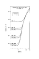
- FIG. 2 is a diagram showing specific resistances of copper and aluminum at extremely low temperatures. Note that FIG. 2 is quoted from the Superconductivity / Cryogenic Engineering Handbook (Cryogenic Engineering Association, published by Ohm Co., Ltd.). The RRR (Residual Resistivity Ratio) shown in FIG. 2 is expressed by the following equation (7).
- the reflectance R has an excellent feature that does not depend on the incident angle of light.
- a metal mirror made of any material of gold, silver, and aluminum also has a reflectivity R of 0.9 to 0.99 at room temperature (for example, 20 ° C.), similarly to the metal mirror made of copper.
- the reflectance R can be increased to 0.99 to 0.999 or more. Therefore, the use efficiency of light in the photochemical reaction can be increased by using the metal mirror having an extremely low temperature for the photochemical reaction.
- the metal used as the material of the metal mirror may be arbitrarily selected as long as there is no problem, but any one of copper, gold, silver, and aluminum is preferably used.
- copper, gold, silver, aluminum and the like having a purity of 99.9999% or more are preferable.
- liquid helium temperature of 4.2 K
- the metal mirror may be cooled so that the temperature is about 40K.
- the reflectance R becomes a value close to 0.99, and the number of reflections can be secured about 100 times. Therefore, the use efficiency of light in the photochemical reaction can also be increased by using a metal mirror cooled to about 100K for the photochemical reaction.
- the temperature of the photochemical reaction cell that performs the photochemical reaction needs to be a temperature suitable for the photochemical reaction. That is, the photochemical reaction is carried out in a gas state, but there is a problem that most of the gas is solidified at the temperature of liquid helium.
- the material of the photochemical reaction cell must transmit laser light without loss.
- the material of the photochemical reaction cell (light-transmitting reaction container 21 shown in FIGS. 3 to 7 described later) is used in an optical fiber, has a purity of 99% or more, and transmits light.
- High-purity synthetic quartz glass or acrylic resin having a loss of 0.1 dB / m or less can be used.
- a process gas necessary for performing the photochemical reaction is enclosed in a container made of high-purity quartz glass (a light-transmitting reaction container 21 shown in FIGS. 3 to 7 described later).
- a first vacuum heat insulating space may be provided between the metal mirror and the light-transmitting reaction container made of quartz glass. Further, the first vacuum heat insulating space may be filled with a rare gas having poor thermal conductivity.
- the optical loss of quartz glass used for the optical fiber is very small as several dB per 1 km, and is much smaller than the optical loss due to the multiple reflection of the reflection mirror, so that it does not cause a problem.
- the laser light is reflected by several percent on the surface (both outer surface and inner surface) of the light transmissive reaction container 21 (the rest is transmitted through the light transmissive reaction container 21).
- the laser light is used without waste because the process gas in the light transmissive reaction container 22 is irradiated with the light, such as being reflected by the light transmissive reaction container 21.
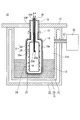
- FIG. 3 is a cross-sectional view showing a schematic configuration of the photochemical reaction device according to the first embodiment of the present invention.
- the photochemical reaction device 10 in FIG. 3 includes a cryostat 11, a lid 13, an annular member 15, a metal container 16, a flange 17, a metal mirror 19, a light-transmitting reaction container 21, and a first vacuum.
- the heat insulating space 23, the heater wire 24, the laser light waveguide member 25, the reliquefaction device 26, and the conduit 27 are included.
- the cryostat 11 includes a first container 31, a second container 32, and a second vacuum heat insulating space 33.
- the first container 31 is a container that contains the cryogenic liquid 12.
- the second container 32 is disposed so as to surround the outer wall of the first container 31 while being separated from the first container 31.
- the second container 32 accommodates the first container 31.
- the second container 32 is configured integrally with the first container 31.
- the shape of the 1st container 31 and the 2nd container 32 can be selected arbitrarily, and a cylinder, a square pillar, etc. can be mentioned as an example.
- the second vacuum heat insulating space 33 is an airtight space provided between the first container 31 and the second container 32.
- the second vacuum heat insulating space 33 is a vacuum. In this way, by providing the second vacuum heat insulating space 33 that is evacuated between the first container 31 and the second container 32, the cryogenic liquid 12 contained in the first container 31 is provided. An increase in temperature can be suppressed.
- the cryostat 11 configured as described above uses the cryogenic liquid 12 to cool and hold the temperature of the metal mirror 19 at an extremely low temperature (100K or less).
- “maintaining the temperature of the metal mirror at a cryogenic temperature” means “the metal mirror is kept cooled by a cryogenic liquid directly or indirectly through a container provided with the metal mirror. "Means.
- the metal mirror may be cooled to a general cryogenic temperature, but may be not cooled to a general cryogenic temperature as long as the effect is obtained, and any temperature can be selected. Moreover, as long as an effect is acquired, the temperature of a metal mirror may be uniform throughout, or may differ partially. If the example of the preferable cooling temperature of a metal mirror is given, as above-mentioned, generally it is 100K or less, More preferably, it is 40K or less, and it is still more preferable that it is liquid helium temperature (4.2K). The amount and type of the cryogenic liquid 12 can be arbitrarily selected, and the method and timing of supplying the cryogenic liquid 12 to the container 31 can be arbitrarily selected as long as there is no problem.
- the temperature of the cooled metal mirror 19 can be selected according to the purpose, and can be appropriately selected within a range of, for example, 100K or less.
- the cryogenic liquid 12 for example, liquid helium (temperature 4.2K) can be preferably used.
- the lid 13 is provided at the upper end of the cryostat 11. Thereby, the space 31A (the space in which the cryogenic liquid 12 and the metal container 16 are accommodated) in the first container 31 is hermetically sealed.
- the lid 13 has a through portion 13A for allowing the annular member 15 to penetrate therethrough.
- the annular member 15 is fixed to the penetrating portion 13 ⁇ / b> A so as to penetrate the lid body 13.
- the upper end of the annular member 15 has a penetrating portion 15A for penetrating a tubular portion 35, which will be described later, constituting the light transmissive reaction vessel 21.
- the lower end of the annular member 15 is an open end.
- the metal container 16 is accommodated in the first container 31 (space 31 ⁇ / b> A) so that a part of the metal container 16 is immersed in the cryogenic liquid 12.
- the upper end of the metal container 16 is fixed to the lower end of the annular member 15 by a flange 17.
- a fixing method using the flange 17 a welding flange, a screwed flange, or the like can be used.
- the flange 17 is provided at the joint between the metal container 16 and the annular member 15.
- the metal container 16 accommodates the light-transmitting reaction container 21 with a gap interposed between the metal container 16 and the light-transmitting reaction container 21.
- the metal container 16 is made of the same type of metal as that constituting the metal mirror 19 and a metal having a purity lower than that of the metal constituting the metal mirror 19.
- the metal used as the material of the metal container 16 can be arbitrarily selected. For example, any one of gold, silver, copper, and aluminum can be used. When gold, silver, copper, aluminum, or the like is used as a metal that is a material of the metal container 16, the purity of the metal can be within a range of 99.9999% or more.
- the metal mirror 19 is provided so as to cover the inner surface 16a of the metal container 16.
- the metal mirror 19 is arranged outside the light transmissive reaction container 21 so as to surround the light transmissive reaction container 21 with a space therebetween.
- the metal mirror 19 reflects the laser beam emitted from the laser beam waveguide member 25 to irradiate the reflected laser beam to the process gas sealed or distributed in the light-transmissive reaction vessel 21.
- the metal constituting the metal mirror 19 can be, for example, 99.9999 or more.
- the reflectance R of the surface of the metal mirror 19 may be 0.9999 or more. it can. Since the reflectance R has an excellent feature that does not depend on the incident angle of the laser light, the shape of the inner surface of the metal container 16 can be freely selected.
- the shape of the inner surface of the metal container 16 is advantageous from the viewpoint of increasing the optical path length, but may be other shapes such as a cylindrical shape or a rectangular shape (a rectangular parallelepiped). Further, there is no need to worry about the spread angle and the optical axis of the laser light emitted from the laser light waveguide member 25. Since most of the irradiated laser light is attenuated by the number of reflections, it can be used for photochemical reaction by multiple reflection to the limit.
- the metal mirror 19 examples include a metal film (specifically, a gold film, a silver film, a copper film, and the like) formed by a method such as a CVD (Chemical Vapor Deposition) method, a plating method, a coating method, and a vapor deposition method.
- a metal film specifically, a gold film, a silver film, a copper film, and the like
- An aluminum film or the like can be used.
- the thickness of the metal film can be arbitrarily selected, for example, 0.02 to 10 ⁇ m.
- the thickness of the metal film can be arbitrarily selected, for example, 20 nm to 1 mm (or 1 mm or more).
- the light-transmitting reaction container 21 has a tubular portion 35 and a reaction chamber 36.
- the tubular portion 35 is fixed to the through portion 15 ⁇ / b> A and extends inside the metal container 16.
- the inner diameter of the tubular portion 35 is configured to be narrower than the inner diameter of the reaction chamber 36.
- one end portion has a process gas supply device (not shown) for supplying a process gas, a process gas recovery device (not shown), and / or an open / close valve or the like communicating with these.
- the other end portion is connected to the reaction chamber 36.
- the reaction chamber 36 is accommodated in the metal container 16 with a gap interposed between the metal mirror 19 and the reaction chamber 36.
- the reaction chamber 36 is configured integrally with the tubular portion 35.
- the process gas is photochemically reacted by laser light.
- the material for the light transmissive reaction vessel 21 can be arbitrarily selected, but it is preferable to use high purity quartz glass having a purity of 99% or more and a light transmission loss of 0.1 dB / m or less, or an acrylic resin.
- the first vacuum heat insulation space 23 is provided between the light transmissive reaction container 21 and the metal mirror 19.
- the 1st vacuum heat insulation space 23 is the space made into the vacuum. As described above, by providing the first vacuum heat insulating space 23 between the light transmissive reaction container 21 and the metal mirror 19, the light transmissive reaction container 21 is hardly cooled by the cryogenic liquid 12. Is possible. Thereby, it can suppress that the process gas supplied in the light transmissive reaction container 21 is solidified.
- the heater wire 24 is wound around the outer wall 36 a of the reaction chamber 36.
- the reaction chamber 36 can be heated by winding the heater wire 24 around the outer wall 36a of the reaction chamber 36, the temperature in the reaction chamber 36 is adjusted to a temperature suitable for the photochemical reaction. Can do.
- the laser light waveguide member 25 is disposed inside the tubular portion 35 and above the reaction chamber 36.
- the laser light waveguide member 25 has a laser irradiation surface 25a for irradiating the tip 25A with laser light.
- the laser light waveguide member 25 is an optical system device configured by a lens, a mirror, or the like, and is a member for introducing laser light into the light transmissive reaction container 21.
- the laser beam waveguide member 25 can be arbitrarily selected, but an optical fiber is preferable.
- FIG. 1 as an example, the case where the laser beam is irradiated from the laser irradiation surface 25a is illustrated, but a lens (not shown) is arranged at the tip 25A of the laser beam waveguide member 25.
- the laser beam may be parallel light.
- the reliquefaction device 26 is provided outside the cryostat 11.
- the reliquefaction device 26 is connected to a conduit 27 that penetrates the side wall of the cryostat 11 and is connected to the space 31 ⁇ / b> A in the first container 31.
- the reliquefaction device 26 is a device that cools the evaporated cryogenic liquid 12 with a pulse tube refrigerator or a Gifford-McMahon refrigerator and reliquefies it back to the cryogenic liquid 12.
- the reliquefaction device 26 and the pipe line 27 may be provided with an opening / closing part (not shown).
- a light transmitting reaction vessel 21 that photochemically reacts a process gas supplied inside with a laser beam, and a light transmitting reaction vessel 21 outside the light transmitting reaction vessel 21.
- a metal mirror 19 disposed so as to surround the transmissive reaction container 21 and reflecting the laser beam; a metal container 16;
- the cryostat 11 is configured to accommodate the light transmissive reaction vessel 21, the metal mirror 19, and the cryogenic liquid 12, and holds the temperature of the metal mirror 19 at an extremely low temperature (a temperature of 100 K or less) by the cryogenic liquid 12.
- liquid helium temperature 4.2 K
- cooling the metal mirror 19 to a temperature close to that of liquid helium a high reflectance R of 0.9999 or more can be realized.
- the utilization efficiency of the laser beam in the photochemical reaction can be increased to the limit.
- a mixed gas of CF 4 and ozone (O 3 ) is used as a process gas, but it goes without saying that the present invention can also be applied to cases where other process gases are used.
- a mixed gas of CF 4 and ozone (O 3 ) is supplied as a process gas to the reaction chamber 36 of the light transmissive reaction vessel 21.
- the laser light waveguide member 25 irradiates the mixed gas supplied into the reaction chamber 36 with laser light, and ozone containing 17 O or 18 O which is an oxygen isotope contained in ozone by a photochemical reaction.
- the isotopologue is selectively photodegraded to oxygen. That is, ozone containing the target oxygen isotope in the molecule is selectively decomposed into oxygen.
- the reflectivity of the laser beam is increased by reflecting the laser beam using the metal mirror 19 cooled to a very low temperature (100K or less), so that the laser beam in the photochemical reaction is reflected.
- Use efficiency can be increased.
- the wavelength region of the laser light can be arbitrarily selected, but it is optimal to use 500 to 1500 nm where the optical loss of the optical fiber is small.
- a laser beam can be introduced by using a reflecting mirror or a lens.
- the wavelength region of the laser beam should be 800 nm or more where the reflectance of the metal mirror 19 is high. preferable.
- the wavelength region of the laser beam when the photochemical reaction is performed using a mixed gas of ozone and CF 4 as a process gas is preferably 700 to 1200 nm called “Wulf Band”.
- oxygen in the mixed gas is separated from undecomposed ozone and CF 4 .
- 17 O or 18 O which is an oxygen isotope, can be concentrated in the separated oxygen.
- ozone (with the photochemical reaction device 10 that reflects laser light by the metal mirror 19 cooled to an extremely low temperature (100K or less) is used.
- a mixed gas in which O 3 ) and CF 4 are mixed is supplied as a process gas to the reaction chamber 36 of the light transmissive reaction vessel 21, and then the mixed gas is irradiated with a laser beam so that the oxygen isotope 17 O or By selectively photolyzing ozone containing 18 O, the oxygen isotope 17 O or 18 O can be concentrated while increasing the utilization efficiency of laser light in the photochemical reaction.
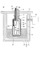
- FIG. 4 is a cross-sectional view showing a schematic configuration of a photochemical reaction device according to the second embodiment of the present invention.
- the same components as those of the photochemical reaction device 10 of the first embodiment shown in FIG. 4 are identical components as those of the photochemical reaction device 10 of the first embodiment shown in FIG.
- the photochemical reaction device 40 of the second embodiment shown in FIG. 4 is provided with a gas supply pipe 41 in the configuration of the photochemical reaction device 10 of the first embodiment, and the laser light waveguide member 25 is the first. Except that the heater wire 24 provided in the photochemical reaction device 10 is excluded from the constituent elements, and is disposed in the vacuum heat insulating space 23 (between the light transmissive reaction vessel 21 and the metal mirror 19). It is configured in the same way.
- the gas supply pipe 41 is disposed in the light transmissive reaction container 21.
- the gas supply pipe 41 is connected to a process gas supply source (not shown) that supplies process gas.
- a tip 41 ⁇ / b> A of the gas supply pipe 41 (a portion for supplying a process gas into the reaction chamber 36) is disposed at a location near the bottom of the reaction chamber 36.
- gas is discharged from the gap between the gas supply pipe 41 and the tubular portion 35.
- the laser light waveguide member 25 is disposed in the first vacuum heat insulating space 23 provided between the light transmissive reaction container 21 and the metal mirror 19. Since the process gas does not come into contact with the laser beam waveguide member 25, contamination of the process gas caused by the laser beam waveguide member 25 can be prevented.
- the photochemical reaction device 40 of the second embodiment can obtain the same effects as the photochemical reaction device 10 of the first embodiment. Specifically, since the reflectance of the laser beam of the metal mirror 19 can be increased, the utilization efficiency of the laser beam in the photochemical reaction can be increased.
- the isotope enrichment method using the photochemical reaction device 40 of the second embodiment can be performed by the same method as the isotope enrichment method using the photochemical reaction device 10 described in the first embodiment.
- the same effect as the isotope enrichment method using the photochemical reaction device 10 can be obtained.
- the heater wire 24 shown in FIG. 1 may be provided.
- FIG. 5 is a cross-sectional view showing a schematic configuration of a photochemical reaction device according to the third embodiment of the present invention.
- the same components as those of the photochemical reaction device 40 of the second embodiment shown in FIG. 5 are identical components as those of the photochemical reaction device 40 of the second embodiment shown in FIG.
- the photochemical reaction device 45 of the third embodiment shown in FIG. 5 is different from the photochemical reaction device 40 of the second embodiment except that a quartz glass container 46 is provided instead of the metal container 16 provided in the photochemical reaction device 40 of the second embodiment.
- the same configuration as that of the photochemical reaction device 40 is performed.
- the quartz glass container 46 is accommodated in the cryostat 11 and also accommodates the light transmissive reaction container 21.
- the quartz glass container 46 is made of high-purity quartz glass that transmits laser light, has a purity of 99% or more, and has a light transmission loss of 0.1 dB / m or less.
- the quartz glass constituting the quartz glass container 46 can have a smaller heat capacity than the metals constituting the metal container 16 (for example, gold, silver, copper, aluminum, etc.).
- the metal mirror 19 is provided so as to cover the inner surface 46 a of the quartz glass container 46.
- a metal film formed by a coating method or a vapor deposition method for example, a gold film, a silver film, a copper film, an aluminum film, etc. having a purity of 99.9999% or more
- the thickness of the metal film can be set to 0.02 to 10 ⁇ m, for example.
- the quartz glass instead of the metal container 16, by providing the quartz glass container 46 that accommodates the light transmissive reaction container 21, the quartz glass has a heat capacity as compared with the metal. Since it is small, the metal mirror 19 can be efficiently cooled by the cryogenic liquid 12. Further, by providing the metal mirror 19 on the inner surface 46 a of the quartz glass container 46, it becomes possible to reduce the tensile stress due to the difference in thermal expansion coefficient between the quartz glass container 46 and the metal mirror 19. A decrease in reflectance R can be suppressed.
- the isotope enrichment method using the photochemical reaction device 45 of the third embodiment can be performed by the same method as the isotope enrichment method using the photochemical reaction device 10 described in the first embodiment. . Further, in the photochemical reaction device 45 of the third embodiment, the heater wire 24 shown in FIG. 1 may be provided.
- FIG. 6 is a cross-sectional view showing a schematic configuration of a photochemical reaction device, which is a modification of the third embodiment of the present invention.
- the same components as those of the photochemical reaction device 45 of the third embodiment shown in FIG. 6 are identical components as those of the photochemical reaction device 45 of the third embodiment shown in FIG. 6
- a photochemical reaction device 50 which is a modification of the third embodiment shown in FIG. 6, has a metal mirror 19 provided in the photochemical reaction device 45 of the third embodiment in a quartz glass container instead of the inner surface.
- 46 external container: first quartz glass container
- the photochemical reaction device 50 which is a modification of the third embodiment having such a configuration, has a quartz glass container 46 that accommodates the light-transmitting reaction container 21, so that a metal mirror is used by the cryogenic liquid 12. 19 can be efficiently cooled.
- the isotope enrichment method using the photochemical reaction device 50 according to the modification of the third embodiment is the same method as the isotope enrichment method using the photochemical reaction device 10 described in the first embodiment. Can be performed. Further, in the photochemical reaction device 50 according to the modification of the third embodiment, the heater wire 24 shown in FIG. 1 may be provided.
- FIG. 7 is sectional drawing which shows schematic structure of the photochemical reaction apparatus which concerns on the 4th Embodiment of this invention.
- the same components as those of the photochemical reaction device 40 of the second embodiment shown in FIG.
- the photochemical reaction device 55 of the fourth embodiment shown in FIG. 7 is provided with a quartz glass container 57 in the configuration of the photochemical reaction device 40 of the second embodiment, and a part of the laser light waveguide member 25 is made of metal.
- the structure is the same as that of the photochemical reaction apparatus 40 except that the container 61 is provided and the annular member 15 and the flange 17 provided in the photochemical reaction apparatus 40 are excluded from the constituent elements.
- the quartz glass container 57 is provided between the light transmissive reaction container 21 and the metal mirror 19.
- the quartz glass container 57 is disposed so as to surround the light transmissive reaction container 21.
- the quartz glass container 57 transmits laser light.
- the quartz glass container 57 is made of high-purity quartz glass having a purity of 99% or more and a light transmission loss of 0.1 dB / m or less.
- a first vacuum heat insulating space 23 is provided between the light transmissive reaction vessel 21 and the quartz glass vessel 57.
- the light transmissive reaction vessel 21 and the quartz glass vessel 57 may be combined at an arbitrary position to form the first vacuum heat insulating space 23.
- the space between the quartz glass container 57 and the metal mirror 19 is not evacuated.
- the metal container 61 is fixed to the first container 31 by an arbitrary method so as to surround the quartz glass container 57 (the fixing method is not shown).
- the metal container 61 is provided with a penetrating portion 62 for disposing the tip 25A of the laser light waveguide member 25 from the outside of the metal container 61 in a space provided between the quartz glass container 57 and the metal mirror 19. ing.
- the laser light waveguide member 25 is disposed outside the quartz glass container 57.
- the same metal as that of the metal container 16 described in the second embodiment can be used.
- the quartz glass container 57 surrounding the light transmissive reaction container 21 is provided, and the first transparent glass container 57 is disposed between the light transmissive reaction container 21 and the quartz glass container 57.
- the vacuum heat insulating space 23 By disposing the vacuum heat insulating space 23, it is not necessary to evacuate the metal container 61. In other words, there is no need to hermetically seal the inside of the metal container 61.
- the metal container 61 can be comprised by assembling a plurality of divided members.
- a sufficient space for arranging a heat insulating jacket for using the optical fiber as the laser light waveguide member 25 at a constant temperature can be secured.
- the metal container 61 and the cryostat 11 are appropriately provided with a window for irradiating laser light (a window through which laser light can be transmitted), a mirror for reflecting the laser light, and the like.
- the heater wire 24 shown in FIG. 1 may be provided.
- the case where one optical fiber is used as the laser light waveguide member 25 has been described as an example.
- a plurality of optical fibers may be provided.
- Table 1 shows an example of the process calculation when enriching the oxygen isotope 17 O.
- the process calculation example shown in Table 1 is for the oxygen isotope enrichment process in Patent Document 2 (Japanese Patent Laid-Open No. 2006-272090) described above.
- Table 1 high purity oxygen as a raw material (16 O, 17 O, and 18 O is the natural abundance levels) twice when performing 2-step enrichment for performing a photochemical reaction by irradiation of laser light, The first stage, the second stage, and the overall result are shown.
- the starting oxygen, the ozonizer, the ozone - converted to oxygen-based gas, after being introduced into the distillation column was introduced CF 4, from the bottom of the distillation column, it is derived as an ozone -CF 4 based gas, ozone —CF 4 -based gas was used as the process gas of the present invention.
- CF 4 ozone -CF 4 based gas
- ozone —CF 4 -based gas was used as the process gas of the present invention.
- 17 O is concentrated, 17 O oxygen in as the final product were concentrated more than 10 atom%.
- the target absorption wavelength of ozone isotopologue 16 O 16 O 17 O containing 17 O is about 1000 nm, and the optical fiber as the laser light waveguide member 25 is in a wavelength region that can be used with low loss. This is important in that the optical fiber to be used can be easily obtained and the photochemical reaction can be performed with the loss of the laser light as small as possible.
- ozone (O 3 ) and CF 4 as process gases are used. Also when the oxygen isotope 17 O in the ozone molecule is concentrated using a mixed gas in which is mixed, the results shown in Table 1 are obtained.
- the present invention is applicable to a photochemical reaction apparatus using a laser beam and an isotope enrichment method using a photochemical reaction apparatus.
- the present invention provides a photochemical reaction apparatus and an isotope enrichment method capable of increasing the utilization efficiency of laser light in a photochemical reaction.
- Photochemical reaction device 11 Cryostat 12 Cryogenic liquid 13 Lid 13A, 15A, 62 Through portion 15 Annular member 16, 61 Metal container 16a, 46a, 61a Inner surface 17 Flange 19 Metal mirror 21 Light transmission Sex reaction container 23 First vacuum heat insulating space 24 Heater wire 25 Laser light guide member 25a Laser irradiation surface 25A, 41A Tip 26 Reliquefaction device 27 Pipe line 31 First container 31A Space 32 Second container 33 Second container 33 Vacuum insulation space 35 Tubular portion 36 Reaction chamber 36a Outer wall 41 Gas supply pipe 46 Quartz glass container (outer container: first quartz glass container) 46b exterior 57 Quartz glass container (inner container: second quartz glass container)
Landscapes
- Physics & Mathematics (AREA)
- Chemical & Material Sciences (AREA)
- Optics & Photonics (AREA)
- Chemical Kinetics & Catalysis (AREA)
- General Physics & Mathematics (AREA)
- Electromagnetism (AREA)
- Toxicology (AREA)
- General Health & Medical Sciences (AREA)
- Organic Chemistry (AREA)
- Health & Medical Sciences (AREA)
- Life Sciences & Earth Sciences (AREA)
- Biophysics (AREA)
- Physical Or Chemical Processes And Apparatus (AREA)
Abstract
Description
本願は、2011年2月23日に、日本に出願された特願2011-037045号に基づき優先権を主張し、その内容をここに援用する。
多重反射方式を使用する場合の光吸収は、下記(1)式に示すようにLambert-Beerの法則で表される。


このような方法を使用する場合、オゾンのwulf band(近赤外領域700~1200nm)における比較的吸収が大きい波長での光吸収断面積σは、10-23cm2/moleculeという小さな値(水の光吸収断面積より約4桁小さい)であり、よって光化学反応セルの光路長としては1000m以上が望まれる。
したがって、上記のような光吸収断面積が小さい光化学反応を行う場合、光化学反応セルは多重反射方式のセルを用いる事が有利である。
反射回数が1000回以上の場合でも光損失が小さいようにするためには、反射率は0.999以上であることを必要とする(この場合の最終光強度は、0.9991000=0.37)。例えば、反射率が0.9999で反射回数を10000回とした場合、最終光強度は0.999910000=0.37となり、1回反射するまでの平均光路長を1mとすると、全光路長は10000m以上となる。
(1)内部に供給されたプロセスガスを、レーザ光により光化学反応させる光透過性反応用容器と、前記光透過性反応用容器の外側に、前記光透過性反応用容器を囲むように配置され、前記レーザ光を反射する金属ミラーと、前記光透過性反応用容器、前記金属ミラー、及び極低温液体を収容する構成であって、前記極低温液体により、前記金属ミラーの温度を極低温に保持するクライオスタットと、を有する光化学反応装置である。
また(1)の光化学反応装置は、以下に示される特徴を有する事も好ましい。
前記金属ミラーが、前記金属容器の内面を覆うように配置される。
前記金属ミラーは、前記石英ガラス容器の内面、または前記石英ガラス容器の外面を覆うように配置される。
(23) (1)から(22)のうち、いずれかの光化学反応装置を用いた同位体濃縮方法であって、前記プロセスガスとしてO3とCF4との混合ガスを、前記光透過性反応用容器内に供給する工程と、その後、前記混合ガスに前記レーザ光を照射して光化学反応させることで、酸素同位体17Oまたは18Oを含む前記O3を選択的に光分解させる工程と、を有することを特徴とする光化学反応装置を用いた同位体濃縮方法。
(24) 上記(23)の同位体濃縮方法は、前記光分解させる際の前記レーザ光の波長領域が、500nm以上である。



図1を参照するに、波長が800nm以上の領域において、反射率は銀>銅>金の順となっており、比抵抗は銀<銅<金の順であるので、上記(4)式が成立している。
なお、ここでいう極低温液体とは、液体窒素、液体酸素、液体アルゴン、液体水素、液体ヘリウムなど、標準沸点が100K以下の液化ガスを意味する。また、そのような液体を使用する温度領域を極低温と呼ぶ。

図2に示すRRR(Residual Resistivity Ratio)は、下記(7)式で表される。


また、上記金属ミラーの材料となる金属は、問題のない限り任意で選択してよいが、銅、金、銀、及びアルミニウムのうち、いずれか1つを用いることが好ましい。
また、金属ミラーの材料となる金属としては、純度が99.9999%以上とされた銅、金、銀、及びアルミニウム等が好ましい。
また、金属ミラーの温度が100K程度となるように冷却した場合でも、反射率Rは0.99に近い値となり、反射回数を100回程度確保することが可能となる。よって、100K程度に冷却された金属ミラーを光化学反応に用いることでも、光化学反応における光の利用効率を高めることができる。
すなわち、光化学反応はガス状態で行うが、液体ヘリウムの温度では、ほとんどのガスが固化してしまう問題があるためである。また、光化学反応セルの材質は、レーザ光を損失無く透過するものでなければならない。
光化学反応を行なう際は、高純度の石英ガラスで製作された容器(後述する図3~図7に示す光透過性反応用容器21)内に、光化学反応を行うために必要なプロセスガスを封入し又は任意で循環させ、一方で、金属ミラーと前記石英ガラスからなる光透過性反応用容器の間には第1の真空断熱空間を設けるとよい。また、第1の真空断熱空間に、熱伝導性の悪い希薄なガス等を充填してもよい。
(第1の実施の形態)
図3は、本発明の第1の実施の形態に係る光化学反応装置の概略構成を示す断面図である。
図3の光化学反応装置10は、クライオスタット11と、蓋体13と、環状部材15と、金属容器16と、フランジ17と、金属ミラー19と、光透過性反応用容器21と、第1の真空断熱空間23と、ヒータ線24と、レーザ光導波部材25と、再液化装置26と、管路27と、を有する。
第2の容器32は、第1の容器31に対して離間した状態で、第1の容器31の外壁を囲むように配置されている。第2の容器32は、第1の容器31を収容している。第2の容器32は、第1の容器31と一体に構成されている。第1の容器31と第2の容器32の形は任意に選択でき、円柱や四角柱などを例として挙げる事ができる。
このように、第1の容器31と第2の容器32との間に、真空とされた第2の真空断熱空間33を設けることにより、第1の容器31に収容された極低温液体12の温度が上昇することを抑制できる。
上記構成とされたクライオスタット11は、極低温液体12により、金属ミラー19の温度を極低温(100K以下)に冷却保持する。
本発明において“金属ミラーの温度を極低温に保持する”とは“金属ミラーが極低温液体によって、直接、又は金属ミラーが設けられた容器を介して間接的に、冷却された状態を維持する”ことを意味する。
よって金属ミラーは一般的な意味の極低温まで冷却されても良いが、効果が得られる限り、一般的な極低温まで冷却されていなくても良く、任意の温度を選択できる。また効果が得られる限り、金属ミラーの温度は全体に均一であっても、あるいは部分的に異なっていても良い。金属ミラーの好ましい冷却温度の例を挙げれば、上述したように一般的には100K以下、より好ましくは40K以下であり、液体ヘリウム温度(4.2K)である事が更に好ましい。
また極低温液体12の量と種類は任意で選択でき、極低温液体12の容器31への供給方法や供給するタイミングも問題のない限り任意に選択できる。
環状部材15は、蓋体13を貫通するように、貫通部13Aに固定されている。環状部材15の上端は、光透過性反応用容器21を構成する後述する管状部35を貫通させるための貫通部15Aを有する。環状部材15の下端は、開放端とされている。環状部材15の材料としては、例えば、ステンレスを用いることができる。
金属容器16は、金属容器16と光透過性反応用容器21との間に隙間を介在させた状態で、光透過性反応用容器21を収容している。
金属ミラー19を構成する金属として、金、銀、銅、アルミニウム等を用いる場合、金属ミラー19を構成する金属の純度は、例えば、99.9999以上とすることができる。
前記反射率Rは、レーザ光の入射角に依存しない優れた特徴があるため、金属容器16内面の形状を自由に選択することができる。金属容器16内面の形状は、光路長を大きくする観点から球形が有利であるが、円筒形や角型(直方体等)などの他の形状でもよい。
また、レーザ光導波部材25から照射されたレーザ光の広がり角や光軸を気にする必要が無い。照射されたレーザ光の大半は、反射回数により減衰するため、極限まで多重反射させることで、光化学反応に利用できる。
金属ミラー19として金属膜を非金属表面にコーティングする場合、前記金属膜の厚さは任意に選択でき、例えば、0.02~10μmとすることができる。また、金属ミラー19として金属膜を金属表面にコーティングする場合、前記金属膜の厚さは任意に選択でき、例えば、20nm~1mm(或いは1mm以上)とすることができる。
このように、光透過性反応用容器21と金属ミラー19との間に、第1の真空断熱空間23を設けることで、極低温液体12により光透過性反応用容器21が冷却されにくくすることが可能となる。これにより、光透過性反応用容器21内に供給されたプロセスガスが固化することを抑制できる。
ここで、レーザ光導波部材25とは、レンズ・ミラー等により構成された、光学システム機器であって、レーザ光を光透過性反応用容器21に導入するための部材である。また、このレーザ光導波部材25は任意に選択可能であるが、光ファイバが好適である。
なお、図1では、一例として、レーザ照射面25aからレーザ光が広がった状態で照射される場合を図示したが、レーザ光導波部材25の先端25Aにレンズ(図示せず)を配置することで、レーザ光を平行光にしてもよい。
このように、第1の容器31内に収容された極低温液体12が蒸発したものを再液化させる再液化装置26を設けることにより、連続して極低温液体12を冷却することが可能となるので、金属ミラー19の温度を安定して極低温に保つことができる。
光透過性反応用容器21、金属ミラー19、及び極低温液体12を収容可能な構成であり、極低温液体12により、金属ミラー19の温度を極低温(100K以下の温度)に保持するクライオスタット11と、を有することにより、金属ミラー19のレーザ光の反射率を高めることが可能となる。これにより、光化学反応におけるレーザ光の利用効率を高めることができる。
始めに、プロセスガスとしてCF4とオゾン(O3)との混合ガスを光透過性反応用容器21の反応室36に供給する。次いで、レーザ光導波部材25により、反応室36内に供給された混合ガスにレーザ光を照射して、光化学反応により、オゾン中に含まれる、酸素同位体である17Oまたは18Oを含むオゾンのアイソトポローグ(isotopologue)を、選択的に酸素に光分解させる。すなわち、分子中に目的の酸素同位体を含むオゾンを、選択的に酸素に分解する。
また、光ファイバを使用しない場合は、例えば、反射鏡やレンズを用いてレーザ光を導入できるが、この場合、レーザ光の波長領域は、金属ミラー19の反射率が高い800nm以上を用いることが好ましい。
また、オゾンとCF4との混合ガスをプロセスガスとして光化学反応を行なう際のレーザ光の波長領域は、Wulf Bandと呼ばれる700~1200nmが好ましい。このように、レーザ光の波長領域を700~1200nmとすることで、酸素同位体17Oまたは18Oを含むオゾンを選択的に分解できるという効果を得ることができる。
図4は、本発明の第2の実施の形態に係る光化学反応装置の概略構成を示す断面図である。図4において、図3に示す第1の実施の形態の光化学反応装置10と同一構成部分には同一符号を付す。
第2の実施の形態の光化学反応装置40では、ガス供給管41と管状部35との隙間からガスを排出する。これにより、第2の実施の形態では、プロセスガスを連続的に流通させることが可能であり、光化学反応の連続処理を行なうことができる。なお連続処理に限らず、一回毎に中身を入れ替える処理を行っても良い。また、プロセスガスの導入時の温度を設定することにより、反応室36の温度を制御できる。
なお、第2の実施の形態の光化学反応装置40において、図1に示すヒータ線24を設けてもよい。
図5は、本発明の第3の実施の形態に係る光化学反応装置の概略構成を示す断面図である。図5において、図4に示す第2の実施の形態の光化学反応装置40と同一構成部分には同一符号を付す。
また、石英ガラス容器46の内面46aに金属ミラー19を設けることにより、石英ガラス容器46と金属ミラー19との熱膨張係数の違いによる引張応力を小さくすることが可能となるので、金属ミラー19の反射率Rの低下を抑制できる。
また、第3の実施の形態の光化学反応装置45において、図1に示すヒータ線24を設けてもよい。
また、第3の実施の形態の変形例に係る光化学反応装置50において、図1に示すヒータ線24を設けてもよい。
図7は、本発明の第4の実施の形態に係る光化学反応装置の概略構成を示す断面図である。図7において、図4に示す第2の実施の形態の光化学反応装置40と同一構成部分には同一符号を付す。
なお光透過性反応用容器21と石英ガラス容器57との間に位置するかぎり、第1の真空断熱空間23の範囲や形状や位置は、任意に選択できる。光透過性反応用容器21と石英ガラス容器57は任意の箇所で結合して第1の真空断熱空間23を形成してもよい。
また、石英ガラス容器57と金属ミラー19との間の空間は、真空とされていない。
金属容器61は、石英ガラス容器57を囲むように第1の容器31に任意の方法で固定されている(固定方法については図示せず)。金属容器61には、石英ガラス容器57と金属ミラー19との間に設けられた空間に、レーザ光導波部材25の先端25Aを、金属容器61の外側から配置するための貫通部62が設けられている。レーザ光導波部材25は、石英ガラス容器57の外側に配置されている。金属容器61の材料としては、第2の実施の形態で説明した金属容器16と同じ金属を用いることができる。
これにより、複数の分割された部材を組み立てることで、金属容器61を構成することができる。
また、光ファイバを用いることなく、直接レーザ照射装置(図示せず)からのレーザ光を光透過性反応用容器21に照射することも可能である。この場合、金属容器61及びクライオスタット11に、レーザ光を照射するための窓(レーザ光を透過可能な窓)及びレーザ光を反射するミラー等を適宜設ける。
また、第4の実施の形態の光化学反応装置55において、図1に示すヒータ線24を設けてもよい。
第4の実施の形態の光化学反応装置55(連続的に光化学反応を起こさせる装置)を用いると共に、プロセスガスとしてオゾン(O3)とCF4とを混合した混合ガスを用いて、オゾン分子中の酸素同位体17Oを濃縮する際の、プロセス計算例を表1に示す。
なお、表1に記載のプロセス計算例は、先に説明した特許文献2(特開2006-272090号公報)における酸素同位体濃縮プロセスについてのものである。
表1には、高純度酸素を原料として(16O、17O、及び18Oは天然存在比の濃度)、2度のレーザ光の照射により光化学反応を行う2段濃縮を行ったときの、1段目、2段目、及び総合結果を示す。
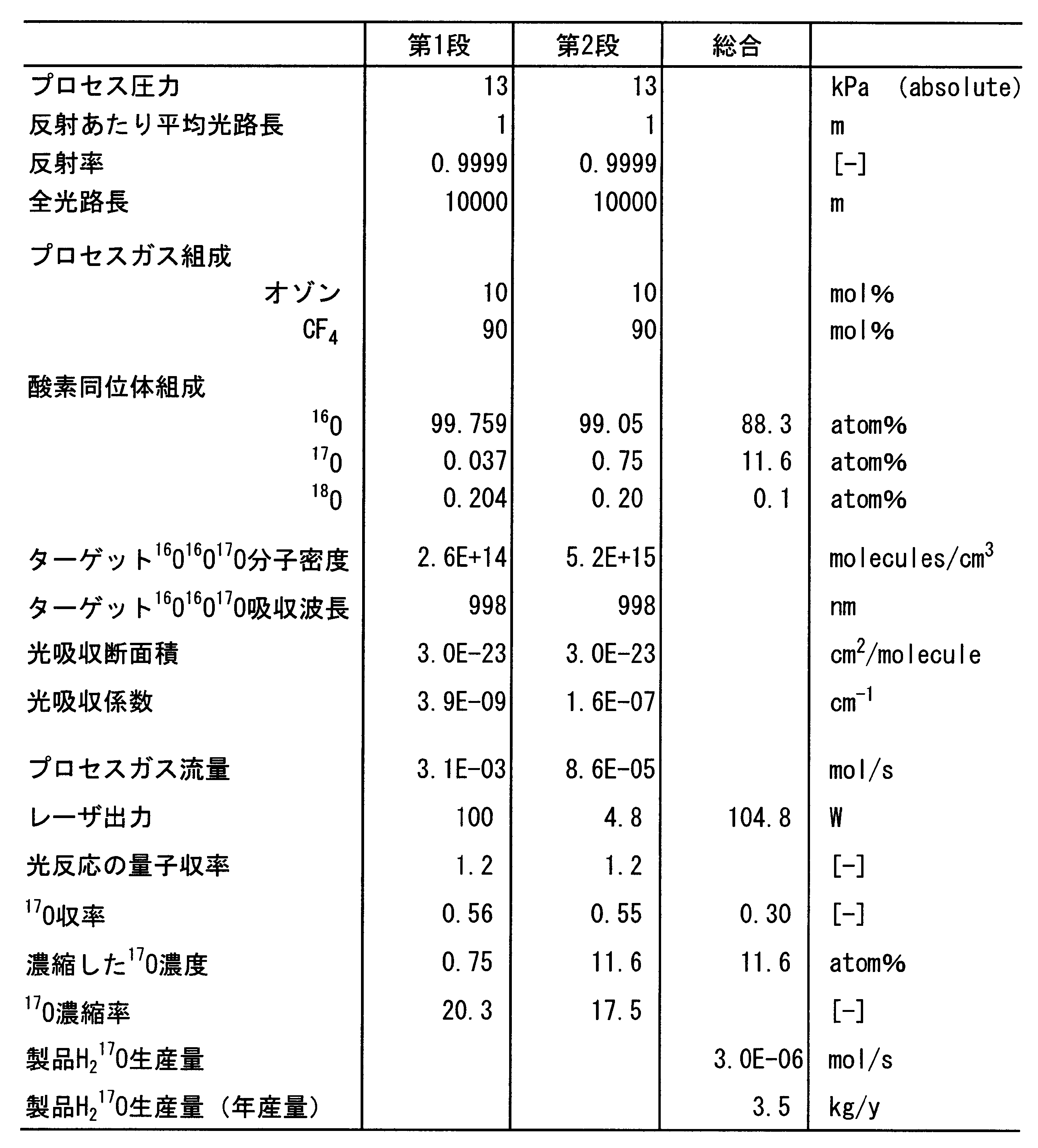
光透過性反応用容器21では、17Oが濃縮され、最終的に製品となる酸素中の17Oは、10atom%以上に濃縮された。
11 クライオスタット
12 極低温液体
13 蓋体
13A,15A,62 貫通部
15 環状部材
16,61 金属容器
16a,46a,61a 内面
17 フランジ
19 金属ミラー
21 光透過性反応用容器
23 第1の真空断熱空間
24 ヒータ線
25 レーザ光導波部材
25a レーザ照射面
25A,41A 先端
26 再液化装置
27 管路
31 第1の容器
31A 空間
32 第2の容器
33 第2の真空断熱空間
35 管状部
36 反応室
36a 外壁
41 ガス供給管
46 石英ガラス容器(外部容器:第1の石英ガラス容器)
46b 外面
57 石英ガラス容器(内部容器:第2の石英ガラス容器)
Claims (25)
- 内部に供給されたプロセスガスを、レーザ光により光化学反応させる光透過性反応用容器と、
前記光透過性反応用容器の外側に、前記光透過性反応用容器を囲むように配置され、前記レーザ光を反射する金属ミラーと、
前記光透過性反応用容器、前記金属ミラー、及び極低温液体を収容する構成であって、前記極低温液体により、前記金属ミラーの温度を極低温に保持するクライオスタットと、
を有する光化学反応装置。 - 前記金属ミラーの温度が、100K以下であることを特徴とする請求項1記載の光化学反応装置。
- 前記光透過性反応用容器と前記金属ミラーとの間に、真空断熱空間を有することを特徴とする請求項1記載の光化学反応装置。
- 前記金属ミラーを構成する金属が、金、銀、銅、アルミニウムのうちのいずれか1つであることを特徴とする請求項1に記載の光化学反応装置。
- 前記金属の純度が、99.9999以上であることを特徴とする請求項4記載の光化学反応装置。
- 前記金属ミラーが、金属膜であることを特徴とする請求項1に記載の光化学反応装置。
- 前記光透過性反応用容器は、石英ガラスまたはアクリル樹脂よりなることを特徴とする請求項1に記載の光化学反応装置。
- 前記プロセスガスに、前記レーザ光を照射する、レーザ光導波部材を有することを特徴とする請求項1に記載の光化学反応装置。
- 前記金属ミラーを構成する金属と同じ種類で、かつ前記金属ミラーを構成する金属よりも純度の低い金属よりなり、前記クライオスタットに収容されると共に、前記光透過性反応用容器を収容する金属容器を有し、
前記金属ミラーを、前記金属容器の内面を覆うように配置したことを特徴とする請求項1に記載の光化学反応装置。 - 前記クライオスタットに収容され、前記光透過性反応用容器を収容すると共に、前記レーザ光を透過する石英ガラス容器を有し、
前記金属ミラーを、前記石英ガラス容器の内面、または前記石英ガラス容器の外面を覆うように配置したことを特徴とする請求項1に記載の光化学反応装置。 - 前記石英ガラス容器は、純度99%以上、かつ光透過損失0.1dB/m以下の高純度の石英ガラスよりなることを特徴とする請求項10記載の光化学反応装置。
- 前記レーザ光導波部材を、前記光透過性反応用容器内に配置したことを特徴とする請求項8に記載の光化学反応装置。
- 前記光透過性反応用容器と前記金属ミラーとの間に、真空断熱空間を有し、前記レーザ光導波部材を、前記真空断熱空間に配置したことを特徴とする請求項8に記載の光化学反応装置。
- 前記レーザ光導波部材は、光ファイバであることを特徴とする請求項8に記載の光化学反応装置。
- 前記光透過性反応用容器の外壁に、ヒータ線を巻きつけたことを特徴とする請求項1に記載の光化学反応装置。
- 前記光透過性反応用容器と前記金属ミラーとの間に、前記レーザ光を透過させ、かつ前記光透過性反応用容器を囲む石英ガラス容器を設け、
前記光透過性反応用容器と前記石英ガラス容器との間に、真空断熱空間を配置したことを特徴とする請求項9記載の光化学反応装置。 - 前記レーザ光導波部材を、前記石英ガラス容器の外側に配置することを特徴とする請求項16記載の光化学反応装置。
- 前記石英ガラス容器は、純度99%以上、かつ光透過損失0.1dB/m以下の高純度の石英ガラスよりなることを特徴とする請求項16に記載の光化学反応装置。
- 前記光透過性反応用容器は、純度99%以上、かつ光透過損失0.1dB/m以下の高純度の石英ガラスよりなることを特徴とする請求項1に記載の光化学反応装置。
- 前記クライオスタットは、前記極低温液体を収容する第1の容器と、前記第1の容器を収容する第2の容器と、前記第1の容器と第2の容器との間に設けられた真空断熱空間と、を有することを特徴とする請求項1に記載の光化学反応装置。
- 前記第1の容器と接続され、前記極低温液体から形成された気体を再液化させる再液化装置を有することを特徴とする請求項20記載の光化学反応装置。
- 前記極低温液体が、液体ヘリウムであることを特徴とする請求項1に記載の光化学反応装置。
- 請求項1の記載の前記光化学反応装置を用いた同位体濃縮方法であって、
前記プロセスガスとしてO3とCF4との混合ガスを、前記光透過性反応用容器内に供給する工程と、
その後、前記混合ガスに前記レーザ光を照射して光化学反応させることで、酸素同位体17Oまたは18Oを含む前記O3を選択的に光分解させる工程と、を有することを特徴とする光化学反応装置を用いた同位体濃縮方法。 - 前記光分解させる際の前記レーザ光の波長領域が、500nm以上であることを特徴とする請求項23記載の光化学反応装置を用いた同位体濃縮方法。
- 前記光分解させる際の前記レーザ光の波長領域が、700~1500nmであることを特徴とする請求項23記載の光化学反応装置を用いた同位体濃縮方法。
Priority Applications (3)
| Application Number | Priority Date | Filing Date | Title |
|---|---|---|---|
| CN2012800079332A CN103347603A (zh) | 2011-02-23 | 2012-01-23 | 光化学反应装置和使用光化学反应装置的同位素浓缩方法 |
| US14/000,689 US20130327632A1 (en) | 2011-02-23 | 2012-01-23 | Photochemical reaction device and isotope enrichment method using the device |
| RU2013142633/05A RU2013142633A (ru) | 2011-02-23 | 2012-01-23 | Устройство для проведения фотохимической реакции и способ обогащения изотопов с его использованием |
Applications Claiming Priority (2)
| Application Number | Priority Date | Filing Date | Title |
|---|---|---|---|
| JP2011037045A JP5632770B2 (ja) | 2011-02-23 | 2011-02-23 | 光化学反応装置、及び光化学反応装置を用いた同位体濃縮方法 |
| JP2011-037045 | 2011-02-23 |
Publications (1)
| Publication Number | Publication Date |
|---|---|
| WO2012114805A1 true WO2012114805A1 (ja) | 2012-08-30 |
Family
ID=46720594
Family Applications (1)
| Application Number | Title | Priority Date | Filing Date |
|---|---|---|---|
| PCT/JP2012/051319 Ceased WO2012114805A1 (ja) | 2011-02-23 | 2012-01-23 | 光化学反応装置及び光化学反応装置を用いた同位体濃縮方法 |
Country Status (5)
| Country | Link |
|---|---|
| US (1) | US20130327632A1 (ja) |
| JP (1) | JP5632770B2 (ja) |
| CN (1) | CN103347603A (ja) |
| RU (1) | RU2013142633A (ja) |
| WO (1) | WO2012114805A1 (ja) |
Families Citing this family (5)
| Publication number | Priority date | Publication date | Assignee | Title |
|---|---|---|---|---|
| CN109641179A (zh) * | 2016-09-09 | 2019-04-16 | 斯凯瑞有限公司 | 浓缩氢同位素的装置和方法 |
| WO2018098189A1 (en) * | 2016-11-22 | 2018-05-31 | Hepatochem, Inc. | Photochemistry device |
| US20180257933A1 (en) | 2017-03-09 | 2018-09-13 | Sustainable Innovations, Inc. | In situ apparatus and method for providing deuterium oxide or tritium oxide in an industrial apparatus or method |
| FR3079759A1 (fr) * | 2018-04-06 | 2019-10-11 | Universite De Nantes | Dispositif de type reacteur photochimique |
| CN111437689B (zh) * | 2020-04-01 | 2021-02-02 | 华中科技大学 | 一种双通道高温光热催化反应装置 |
Citations (7)
| Publication number | Priority date | Publication date | Assignee | Title |
|---|---|---|---|---|
| JPS63166431A (ja) * | 1986-12-29 | 1988-07-09 | Ishikawajima Harima Heavy Ind Co Ltd | 光反応装置 |
| JPH0332885A (ja) | 1989-06-29 | 1991-02-13 | Kuraray Co Ltd | 光情報記録媒体 |
| JPH07150270A (ja) | 1993-11-30 | 1995-06-13 | Sumitomo Electric Ind Ltd | 金属多孔質材、その製造方法およびそれを用いた電池用電極 |
| JPH07265669A (ja) | 1994-03-30 | 1995-10-17 | Mitsubishi Electric Corp | 多重反射光学装置 |
| JP2006272090A (ja) | 2005-03-28 | 2006-10-12 | Taiyo Nippon Sanso Corp | 酸素同位体の濃縮方法及び濃縮装置 |
| JP2009233492A (ja) * | 2008-03-26 | 2009-10-15 | Taiyo Nippon Sanso Corp | 酸素同位体の濃縮方法 |
| JP4364529B2 (ja) | 2003-03-04 | 2009-11-18 | 大陽日酸株式会社 | 酸素同位体の濃縮方法及び装置 |
Family Cites Families (7)
| Publication number | Priority date | Publication date | Assignee | Title |
|---|---|---|---|---|
| DE2443216C3 (de) * | 1974-09-10 | 1979-02-08 | Kraftwerk Union Ag, 4330 Muelheim | Verfahren und Vorrichtung zur Isotopenanreicherung |
| US4437958A (en) * | 1978-01-11 | 1984-03-20 | The United States Of America As Represented By The United States Department Of Energy | Device and method for separating oxygen isotopes |
| US4220510A (en) * | 1978-07-13 | 1980-09-02 | Massachusetts Institute Of Technology | Method for separating isotopes in the liquid phase at cryogenic temperature |
| CN1256794C (zh) * | 1998-11-10 | 2006-05-17 | 株式会社Idx技术 | 光反应装置 |
| JP3426563B2 (ja) * | 2000-04-26 | 2003-07-14 | 日本電信電話株式会社 | 光化学反応セル |
| US7466731B2 (en) * | 2006-02-24 | 2008-12-16 | Northrop Grumman Corporation | High efficiency, high power cryogenic laser system |
| CN101200449A (zh) * | 2006-12-11 | 2008-06-18 | 天津师范大学 | 管式常压气相吡啶光氯化装置 |
-
2011
- 2011-02-23 JP JP2011037045A patent/JP5632770B2/ja not_active Expired - Fee Related
-
2012
- 2012-01-23 CN CN2012800079332A patent/CN103347603A/zh active Pending
- 2012-01-23 WO PCT/JP2012/051319 patent/WO2012114805A1/ja not_active Ceased
- 2012-01-23 US US14/000,689 patent/US20130327632A1/en not_active Abandoned
- 2012-01-23 RU RU2013142633/05A patent/RU2013142633A/ru not_active Application Discontinuation
Patent Citations (7)
| Publication number | Priority date | Publication date | Assignee | Title |
|---|---|---|---|---|
| JPS63166431A (ja) * | 1986-12-29 | 1988-07-09 | Ishikawajima Harima Heavy Ind Co Ltd | 光反応装置 |
| JPH0332885A (ja) | 1989-06-29 | 1991-02-13 | Kuraray Co Ltd | 光情報記録媒体 |
| JPH07150270A (ja) | 1993-11-30 | 1995-06-13 | Sumitomo Electric Ind Ltd | 金属多孔質材、その製造方法およびそれを用いた電池用電極 |
| JPH07265669A (ja) | 1994-03-30 | 1995-10-17 | Mitsubishi Electric Corp | 多重反射光学装置 |
| JP4364529B2 (ja) | 2003-03-04 | 2009-11-18 | 大陽日酸株式会社 | 酸素同位体の濃縮方法及び装置 |
| JP2006272090A (ja) | 2005-03-28 | 2006-10-12 | Taiyo Nippon Sanso Corp | 酸素同位体の濃縮方法及び濃縮装置 |
| JP2009233492A (ja) * | 2008-03-26 | 2009-10-15 | Taiyo Nippon Sanso Corp | 酸素同位体の濃縮方法 |
Non-Patent Citations (1)
| Title |
|---|
| "Handbook on Materials for Superconducting Machinery", 1977, OHMSHA, LTD., pages: 1084 |
Also Published As
| Publication number | Publication date |
|---|---|
| JP5632770B2 (ja) | 2014-11-26 |
| JP2012170916A (ja) | 2012-09-10 |
| CN103347603A (zh) | 2013-10-09 |
| RU2013142633A (ru) | 2015-04-10 |
| US20130327632A1 (en) | 2013-12-12 |
Similar Documents
| Publication | Publication Date | Title |
|---|---|---|
| JP5632770B2 (ja) | 光化学反応装置、及び光化学反応装置を用いた同位体濃縮方法 | |
| Antiñolo et al. | Reactivity of OH and CH3OH between 22 and 64 K: modeling the gas phase production of CH3O in Barnard 1b | |
| Kimura et al. | Melting temperatures of H2O up to 72 GPa measured in a diamond anvil cell using CO2 laser heating technique | |
| Chaabouni et al. | Water formation through O2+ D pathway on cold silicate and amorphous water ice surfaces of interstellar interest | |
| Chen et al. | A scalable pathway to nanostructured sapphire optical fiber for evanescent-field sensing and beyond | |
| Mohsenian et al. | Design and characterization of a solar-enhanced microwave plasma reactor for atmospheric pressure carbon dioxide decomposition | |
| Rodriguez de Marcos et al. | Room temperature plasma-etching and surface passivation of far-ultraviolet Al mirrors using electron beam generated plasmas | |
| Mochalov et al. | Influence of the preparation technique on the optical properties and content of heterophase inclusions of As2S3 chalcogenide glasses | |
| Nataraj et al. | Quantum cascade laser absorption spectrometer with a low temperature multipass cell for precision clumped CO2 measurement | |
| Brown et al. | High temperature furnace system for vacuum ultraviolet spectroscopic studies | |
| Suck et al. | Role of various water clusters in IR absorption in the 8–14-μ m window region | |
| Matsuura et al. | Hollow optical fibers for ultraviolet and vacuum ultraviolet light | |
| Blickensderfer et al. | A long path, low temperature cell | |
| Ridenti et al. | CN (B 2Σ+→ X 2Σ+) Violet System in a Cold Atmospheric-Pressure Argon Plasma Jet | |
| JP5715473B2 (ja) | 金属ミラーの表面の改質方法 | |
| Velmuzhov et al. | Distillation with separate condensation of components as a new way to prepare especially pure GexTe100− x glasses with precisely desired composition | |
| US10527783B2 (en) | Transition metal doped zinc selenide optical fibers and methods for making the same | |
| JP2013123704A (ja) | 光化学反応装置 | |
| Jing et al. | A simple way to establish a dual-core hollow fiber for laser surgery applications | |
| Jovović et al. | Measurement of C2 and CH temperatures in argon‐acetylene low‐pressure microwave‐induced plasma | |
| Burgess et al. | The mercury-photosensitized hydrogen+ oxygen reaction | |
| US3734056A (en) | Infrared spectroscopy apparatus | |
| WO2018211820A1 (ja) | 物、装置、及び処理方法 | |
| Faber et al. | Optical characterization of infrared telluride glass fibers for space use | |
| Kato et al. | Hexagonal ZnO microdisk grown by mist chemical vapor deposition on c-plane sapphire substrate and lasing actions |
Legal Events
| Date | Code | Title | Description |
|---|---|---|---|
| 121 | Ep: the epo has been informed by wipo that ep was designated in this application |
Ref document number: 12749019 Country of ref document: EP Kind code of ref document: A1 |
|
| WWE | Wipo information: entry into national phase |
Ref document number: 14000689 Country of ref document: US |
|
| NENP | Non-entry into the national phase |
Ref country code: DE |
|
| ENP | Entry into the national phase |
Ref document number: 2013142633 Country of ref document: RU Kind code of ref document: A |
|
| WWE | Wipo information: entry into national phase |
Ref document number: 2012749019 Country of ref document: EP |