WO2012114507A1 - 超電導ケーブル冷却システム - Google Patents
超電導ケーブル冷却システム Download PDFInfo
- Publication number
- WO2012114507A1 WO2012114507A1 PCT/JP2011/054312 JP2011054312W WO2012114507A1 WO 2012114507 A1 WO2012114507 A1 WO 2012114507A1 JP 2011054312 W JP2011054312 W JP 2011054312W WO 2012114507 A1 WO2012114507 A1 WO 2012114507A1
- Authority
- WO
- WIPO (PCT)
- Prior art keywords
- superconducting cable
- temperature
- heat exchange
- heat
- cooling system
- Prior art date
- Legal status (The legal status is an assumption and is not a legal conclusion. Google has not performed a legal analysis and makes no representation as to the accuracy of the status listed.)
- Ceased
Links
Images






Classifications
-
- H—ELECTRICITY
- H01—ELECTRIC ELEMENTS
- H01B—CABLES; CONDUCTORS; INSULATORS; SELECTION OF MATERIALS FOR THEIR CONDUCTIVE, INSULATING OR DIELECTRIC PROPERTIES
- H01B12/00—Superconductive or hyperconductive conductors, cables, or transmission lines
- H01B12/16—Superconductive or hyperconductive conductors, cables, or transmission lines characterised by cooling
-
- F—MECHANICAL ENGINEERING; LIGHTING; HEATING; WEAPONS; BLASTING
- F25—REFRIGERATION OR COOLING; COMBINED HEATING AND REFRIGERATION SYSTEMS; HEAT PUMP SYSTEMS; MANUFACTURE OR STORAGE OF ICE; LIQUEFACTION SOLIDIFICATION OF GASES
- F25B—REFRIGERATION MACHINES, PLANTS OR SYSTEMS; COMBINED HEATING AND REFRIGERATION SYSTEMS; HEAT PUMP SYSTEMS
- F25B9/00—Compression machines, plants or systems, in which the refrigerant is air or other gas of low boiling point
- F25B9/14—Compression machines, plants or systems, in which the refrigerant is air or other gas of low boiling point characterised by the cycle used, e.g. Stirling cycle
-
- F—MECHANICAL ENGINEERING; LIGHTING; HEATING; WEAPONS; BLASTING
- F25—REFRIGERATION OR COOLING; COMBINED HEATING AND REFRIGERATION SYSTEMS; HEAT PUMP SYSTEMS; MANUFACTURE OR STORAGE OF ICE; LIQUEFACTION SOLIDIFICATION OF GASES
- F25D—REFRIGERATORS; COLD ROOMS; ICE-BOXES; COOLING OR FREEZING APPARATUS NOT OTHERWISE PROVIDED FOR
- F25D16/00—Devices using a combination of a cooling mode associated with refrigerating machinery with a cooling mode not associated with refrigerating machinery
-
- F—MECHANICAL ENGINEERING; LIGHTING; HEATING; WEAPONS; BLASTING
- F25—REFRIGERATION OR COOLING; COMBINED HEATING AND REFRIGERATION SYSTEMS; HEAT PUMP SYSTEMS; MANUFACTURE OR STORAGE OF ICE; LIQUEFACTION SOLIDIFICATION OF GASES
- F25D—REFRIGERATORS; COLD ROOMS; ICE-BOXES; COOLING OR FREEZING APPARATUS NOT OTHERWISE PROVIDED FOR
- F25D3/00—Devices using other cold materials; Devices using cold-storage bodies
- F25D3/10—Devices using other cold materials; Devices using cold-storage bodies using liquefied gases, e.g. liquid air
-
- F—MECHANICAL ENGINEERING; LIGHTING; HEATING; WEAPONS; BLASTING
- F28—HEAT EXCHANGE IN GENERAL
- F28F—DETAILS OF HEAT-EXCHANGE AND HEAT-TRANSFER APPARATUS, OF GENERAL APPLICATION
- F28F1/00—Tubular elements; Assemblies of tubular elements
-
- H—ELECTRICITY
- H02—GENERATION; CONVERSION OR DISTRIBUTION OF ELECTRIC POWER
- H02G—INSTALLATION OF ELECTRIC CABLES OR LINES, OR OF COMBINED OPTICAL AND ELECTRIC CABLES OR LINES
- H02G15/00—Cable fittings
- H02G15/34—Cable fittings for cryogenic cables
-
- F—MECHANICAL ENGINEERING; LIGHTING; HEATING; WEAPONS; BLASTING
- F25—REFRIGERATION OR COOLING; COMBINED HEATING AND REFRIGERATION SYSTEMS; HEAT PUMP SYSTEMS; MANUFACTURE OR STORAGE OF ICE; LIQUEFACTION SOLIDIFICATION OF GASES
- F25B—REFRIGERATION MACHINES, PLANTS OR SYSTEMS; COMBINED HEATING AND REFRIGERATION SYSTEMS; HEAT PUMP SYSTEMS
- F25B2700/00—Sensing or detecting of parameters; Sensors therefor
- F25B2700/13—Mass flow of refrigerants
-
- F—MECHANICAL ENGINEERING; LIGHTING; HEATING; WEAPONS; BLASTING
- F25—REFRIGERATION OR COOLING; COMBINED HEATING AND REFRIGERATION SYSTEMS; HEAT PUMP SYSTEMS; MANUFACTURE OR STORAGE OF ICE; LIQUEFACTION SOLIDIFICATION OF GASES
- F25B—REFRIGERATION MACHINES, PLANTS OR SYSTEMS; COMBINED HEATING AND REFRIGERATION SYSTEMS; HEAT PUMP SYSTEMS
- F25B2700/00—Sensing or detecting of parameters; Sensors therefor
- F25B2700/21—Temperatures
-
- Y—GENERAL TAGGING OF NEW TECHNOLOGICAL DEVELOPMENTS; GENERAL TAGGING OF CROSS-SECTIONAL TECHNOLOGIES SPANNING OVER SEVERAL SECTIONS OF THE IPC; TECHNICAL SUBJECTS COVERED BY FORMER USPC CROSS-REFERENCE ART COLLECTIONS [XRACs] AND DIGESTS
- Y02—TECHNOLOGIES OR APPLICATIONS FOR MITIGATION OR ADAPTATION AGAINST CLIMATE CHANGE
- Y02E—REDUCTION OF GREENHOUSE GAS [GHG] EMISSIONS, RELATED TO ENERGY GENERATION, TRANSMISSION OR DISTRIBUTION
- Y02E40/00—Technologies for an efficient electrical power generation, transmission or distribution
- Y02E40/60—Superconducting electric elements or equipment; Power systems integrating superconducting elements or equipment
Definitions
- the present invention relates to a technical field of a superconducting cable cooling system for cooling a superconducting cable used for power transmission / distribution to a cryogenic temperature.
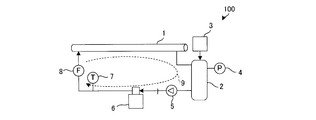
- FIG. 10 is a configuration diagram schematically showing an overall configuration of a conventional superconducting cable cooling system 100.
- the cooling system 100 has a superconducting cable 1 made of a high-temperature superconductor as an object to be cooled, and uses liquid nitrogen as a cooling refrigerant for the superconducting cable 1.
- the refrigerant that has cooled the superconducting cable 1 is temporarily stored in the reservoir tank 2.
- the refrigerant is pressurized to a predetermined pressure value by the pressurizing device 3 and stored.
- the predetermined pressure value is acquired by a controller of the pressurizing device 3 (not shown) obtained by the pressure sensor 4 provided in the reservoir tank 2 so that the acquired pressure value becomes a predetermined value.
- the pressure device 3 is maintained by feedback control.
- a circulation pump 5 is provided on the downstream side of the reservoir tank 2, and the refrigerant stored in the reservoir tank 2 by driving the circulation pump 5 is pumped to the refrigerator 6 and cooled.
- the refrigerator 6 is a GM refrigerator or a Stirling refrigerator. Then, the refrigerant cooled by the refrigerator 6 is supplied again to the superconducting cable 1 and used for cooling in the superconducting state.
- a temperature sensor 7 and a flow rate sensor 8 for detecting the temperature and flow rate of the refrigerant are provided on the downstream side of the refrigerator 6, and the temperature of the refrigerant is cooled to a predetermined value based on each detected value.
- the refrigerator 6 is feedback-controlled.
- Patent Document 1 is an example of a cooling system in which the refrigerant is cooled and supplied to the superconducting cable 1 in such a circulation cycle.
- the refrigerant supply inlet to the superconducting cable 1 (in FIG. It is required to control the temperature of the refrigerant on the downstream side of the sensor 8 at a constant level. There are three major heat losses that occur when the superconducting cable 1 is cooled.
- the refrigerant temperature is controlled by feedback control based on the detection values in the temperature sensor 7 and the flow sensor 8.
- Such control is useful in static systems where the heat loss is constant over time.
- the heat loss generated in the superconducting cable 1 may fluctuate with time as described above. In such a case, there is a problem that the temperature control of the refrigerant becomes difficult.
- a GM refrigerator or a Stirling refrigerator is used as the refrigerator 6. Therefore, the temperature control of the refrigerant is performed by the intermittent operation in the GM refrigerator and the operation cycle control in the Stirling refrigerator.
- this kind of refrigerator 6 it is necessary to control the parameters of the refrigerator 6 by measuring control parameters such as temperature and flow rate at predetermined measurement points in the circulation path 9.
- the superconducting cable is a large-scale cable having a length of several kilometers in consideration of practical use, it is not easy to select the optimum position of the measurement point.
- the length of the superconducting cable 1 is on the order of several kilometers, the flow rate of the refrigerant actually assumed is assumed to be about several tens of cm / s.
- the time required for the refrigerant to make a round of the circulation path 9 reaches several hours, and the time constant for circulating the refrigerant becomes very large.
- the time constant for example, the clock frequency of the controller
- the time constant related to the operation of the refrigerator 6 that controls the temperature of the refrigerant is very short, and there is a large difference between the time constant for circulating the refrigerant. Therefore, in the above example, there is a problem that it is not easy to control the refrigerant inlet temperature to be constant in a dynamic system such as when heat loss in the superconducting cable 1 fluctuates with time.
- the present invention has been made in view of the above problems, and an object thereof is to provide a superconducting cable cooling system capable of supplying a refrigerant having a stable temperature to the superconducting cable.
- the superconducting cable cooling system sends the refrigerant used for cooling the superconducting cable to the heat exchange section with a circulation pump and cools it with a refrigerator, and then to the superconducting cable.
- the superconducting cable cooling system for cooling the superconducting cable by supplying and forming a circulation path, heat exchange having a cooling space filled with a liquefied gas for heat exchange between the heat exchanging unit and the refrigerator A unit, a flow rate detection means for detecting the flow rate of the refrigerant in the circulation path, a temperature detection means for detecting the temperature of the liquefied gas filled in the heat exchange unit, and the flow rate detection means Based on the flow rate and the temperature detected by the temperature detection means, the temperature of the liquefied gas filled in the heat exchange unit is determined. Characterized by comprising a control unit for controlling the refrigerator so that the value.
- the refrigerant that has been used for cooling the superconducting cable and whose temperature has risen is pumped to the heat exchange unit provided on the circulation path by the circulation pump, and is liquefied in the cooling space by the heat exchange unit. It is cooled by exchanging heat with gas. At this time, the amount of heat received from the superconducting cable by the refrigerant flowing through the circulation path is stored in the liquefied gas, and the heat load accumulated in the liquefied gas is removed by the refrigerator. That is, in the present invention, the liquefied gas can function as a thermal buffer by temporarily storing the heat load from the superconducting cable in the liquefied gas.
- the refrigerator can control the temperature of the liquefied gas to a predetermined value, so that the temperature of the refrigerant can be stably maintained even when the amount of heat generated in the superconducting cable varies with time. Can be controlled.
- the refrigerator is a Brayton cycle refrigerator having a Brayton cycle heat exchange unit disposed in the cooling space.
- the Brayton cycle refrigerator is a refrigerator that performs cooling by a compressor and an expander, and has a Brayton cycle heat exchange unit as a heat exchange unit.
- heat exchange is performed using the liquefied gas filled in the cooling space as a medium.
- the superconducting cable can be cooled.
- a reservoir tank that pressurizes and stores the refrigerant flowing through the circulation path to a predetermined pressure may be connected to the circulation path.
- the circulation path is formed corresponding to each of the superconducting cables, and the heat exchange unit in each of the circulation paths is a single It is arranged in the cooling space.
- the heat exchange part provided in each circulation path is arrange
- a heat exchange part included in a circulation path formed corresponding to an adjacent superconducting cable among the plurality of superconducting cables is included in the cooling space. It is good to be arranged in.
- a superconducting cable is used for long-distance power transmission, a plurality of superconducting cables may be connected in series to increase the distance.
- a circulation path is formed for each of the plurality of superconducting cables connected in series as described above, and the heat exchange unit provided in the circulation path corresponding to the adjacent superconducting cable is included in a single cooling space.
- a pressure reducing means for reducing the pressure of the liquefied gas filled in the cooling space of the heat exchange unit may be further provided. According to this aspect, even when the refrigerator is stopped for some reason such as inspection or failure, the liquefied gas can be cooled by reducing the pressure of the liquefied gas by the pressure reducing means. That is, since the decompression means can function as a backup means when the refrigerator is stopped, a cooling system with higher reliability can be constructed.
- a plurality of the heat exchange units may be provided in the circulation path, and the circulation pump may be provided between any of the plurality of heat exchange units.
- the circulation pump may be provided between any of the plurality of heat exchange units.
- the refrigerant that has been used for cooling the superconducting cable and whose temperature has risen is pumped to the heat exchange unit provided on the circulation path by the circulation pump, and is liquefied in the cooling space by the heat exchange unit. It is cooled by exchanging heat with gas. At this time, the amount of heat received from the superconducting cable by the refrigerant flowing through the circulation path is stored in the liquefied gas, and the heat load accumulated in the liquefied gas is removed by the refrigerator. That is, in the present invention, the liquefied gas can function as a thermal buffer by temporarily storing the heat load from the superconducting cable in the liquefied gas.
- the refrigerator can control the temperature of the liquefied gas to a predetermined value, so that the temperature of the refrigerant can be stably maintained even when the amount of heat generated in the superconducting cable varies with time. Can be controlled.
- coolant It is a block diagram which shows roughly the whole structure of the superconducting cable cooling system which concerns on 2nd Example. It is a block diagram which shows schematically the whole structure of the superconducting cable cooling system which concerns on 3rd Example. It is a block diagram which shows roughly the whole structure of the superconducting cable cooling system which concerns on 4th Example. It is a block diagram which shows roughly the whole structure of the superconducting cable cooling system which concerns on 5th Example.
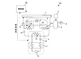
- FIG. 1 is a block diagram schematically showing the overall configuration of a superconducting cable cooling system 100 according to the first embodiment. Note that portions common to the background art described with reference to FIG. 10 are denoted by common reference numerals, and description of details is omitted as appropriate.
- the cooling system 100 forms the circulation path 9 by supplying the refrigerant used for cooling the superconducting cable 1 to the heat exchanging unit 17 with the circulation pump 5 and cooling it, and then supplying the refrigerant again to the superconducting cable 1.
- the superconducting cable 1 is cooled.
- Superconducting cable 1 is formed of a high-temperature superconductor and is cooled by a refrigerant (liquid nitrogen) flowing through circulation path 9.
- a refrigerant liquid nitrogen flowing through circulation path 9.
- the refrigerant flowing through the circulation path 9 is not shown in FIG. 1, the surroundings of the flow path are basically depressurized except for the vicinity of the heat exchanging portion 17 to prevent heat from entering from the outside. It is configured as possible.
- the reservoir tank 2 for pressurizing and storing the refrigerant flowing through the circulation path 9 to a predetermined value is connected to the upstream side of the circulation pump 5 in the circulation path 9. Since the volume of the refrigerant flowing through the circulation path 9 fluctuates due to a temperature change, the reservoir tank 2 absorbs this volume fluctuation and makes the refrigerant difficult to vaporize due to a temperature rise. Pressurize and store. As a result, the refrigerant flowing through the circulation path 9 is less likely to vaporize, and it is possible to improve the response performance when the amount of heat generated in the superconducting cable 1 fluctuates over time.
- the refrigerant flowing through the circulation path 9 is pumped to the heat exchange unit 17 by the circulation pump 5.
- the heat exchanging part 17 is formed so as to use a material having a high heat conductivity or to have a high heat transfer coefficient, so that the amount of heat received from the refrigerant flowing through the heat exchange part can be exchanged with the outside.
- the circulation path 9 forms a pipe-like flow path made of a material having a thermal conductivity such as metal, and is formed so that the coolant flows inside.
- the shape may be appropriately devised by having a large surface area like a radiator as necessary.
- the outside of the heat exchange unit 17 is filled with a low-temperature liquefied gas, and the refrigerant flowing inside the heat exchange unit 17 exchanges heat with the liquefied gas filled outside. It is cooled by.
- the refrigerant cooled in the heat exchange unit 17 passes through the flow rate sensor 8 provided on the downstream side, and then is supplied to the superconducting cable 1 again. Thereby, the refrigerant
- the flow rate sensor 8 is a flow rate detection means for detecting the flow rate of the refrigerant flowing through the circulation path 9 and transmits the detected flow rate value to the control unit 50.
- the heat exchange unit 17 is disposed in a heat exchange unit 14 having a cooling space 15 filled (enclosed) with liquefied gas.
- the liquefied gas filled in the cooling space 15 is liquid nitrogen, similar to the refrigerant flowing in the circulation path 9.
- the liquefied gas it is more preferable to use slush nitrogen in which liquid nitrogen and solid nitrogen are mixed.
- the refrigerator 6 is a Brayton cycle refrigerator, and includes a compressor 10, a heat exchanger 11, an expander 12, and a Brayton cycle heat exchange unit 13.
- the Brayton cycle heat exchanging unit 13 is disposed in the cooling space 15 of the heat exchanging unit 14 filled with the liquefied gas together with the heat exchanging unit 17 described above.
- a gas having a liquefaction temperature lower than that of the liquefied gas filled in the cooling space 15 is circulated.
- liquid nitrogen is used as the liquefied gas filled in the cooling space 15
- helium gas or neon gas is preferable as an example of the gas circulated in the refrigerator 6.
- the Brayton cycle heat exchange unit 13 is at a temperature sufficiently lower than the liquefied gas filled in the cooling space 15 by circulating these gases in the refrigerator 6. Therefore, the cooling temperature of the liquefied gas filled in the cooling space 15 can be controlled by controlling the operating state of the refrigerator 6.
- the refrigerant flowing through the heat exchange unit 17 receives the amount of heat generated in the superconducting cable 1 when passing through the superconducting cable 1, and further receives the amount of heat when pumped by the circulation pump 5, thereby increasing the temperature. .
- the heat exchanging unit 17 is cooled by exchanging heat with the liquefied gas filled in the cooling space 15 with the amount of heat accumulated in the refrigerant in this way.
- the temperature of the liquefied gas can be controlled by controlling the operating state of the refrigerator 6 as described above.
- the refrigerant flowing through the heat exchange unit 17 can be ideally cooled to the same temperature as the liquefied gas in the heat exchange unit 14, in reality, the heat exchange area of the heat exchange unit 17 is limited, so the temperature of the refrigerant Is slightly higher than the temperature in the heat exchange unit 14.
- the temperature of the liquefied gas filled in the cooling space 15 is detected by a temperature sensor 7 serving as a temperature detecting means provided in the heat exchange unit 14.
- the temperature of the liquefied gas detected by the temperature sensor 7 is transmitted to the control unit 50 as an electric signal.
- the control unit 50 is a control unit for controlling the operation state of the refrigerator 6 by transmitting a control signal to the refrigerator 6 based on the information acquired from the flow sensor 8 and the temperature sensor 7.
- a control signal to the refrigerator 6 based on the information acquired from the flow sensor 8 and the temperature sensor 7.
- the heat generation in the superconducting cable 1 is P C [W]
- the generation period of the heat generation is t 1 [seconds]
- the heat generation in the circulation pump 5 is P P [W]
- the operation time of the circulation pump 5 is t P [seconds].
- the mass of the liquefied gas filled in the cooling space 15 is M [kg]
- the specific heat is C [J / (K ⁇ kg)]
- the cooling capacity of the Brayton cycle refrigerator 6 is P b [W].
- the flow rate of the refrigerant that cools the superconducting cable 1 is m [kg / sec].
- This calorific value Q is stored in the liquefied gas filled in the cooling space 15, and assuming that the liquefied gas is not cooled by the refrigerator 6, the temperature of the liquefied gas rises by a temperature ⁇ T calculated by the following equation.
- FIG. 2 is a graph showing an example of temporal transition of the amount of heat generated in the superconducting cable 1.
- the heat generation of the superconducting cable 1, period t 1 at P C1, the period t 2 in P C2, is described on the assumption that these condition continues alternately.
- the control unit 50 may control the refrigerator 6 to cool the average value of the amount of heat generated in the superconducting cable 1.
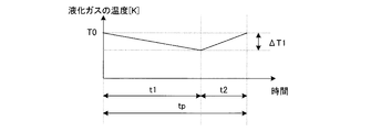
- FIG. 3 is a graph showing the temporal transition of the temperature of the liquefied gas filled in the cooling space 15 when the cooling capacity Pb of the refrigerator 6 is controlled according to the equation (5).
- the cooling capacity Pb of the refrigerator 6 is controlled to be constant so as to cool the average value of the amount of heat generated in the superconducting cable 1, and therefore the calorific value is smaller in the period t 1 than in the period t 2 ( As shown in FIG. 2, the temperature of the liquefied gas gradually decreases. Meanwhile, since many heat value as compared with the period t 2 in the period t 1, the temperature of the liquefied gas is gradually increased and returns to the initial temperature T0.
- ⁇ T 1 (P C2 + P P ⁇ P b ) ⁇ t 2 / (M ⁇ C) (8)
- T C Ts + ⁇ T C (9) It becomes.
- [Delta] T C is the temperature difference determined by the heat exchange efficiency of the heat exchange section 4 of the heat exchange unit 14, by selecting the configuration and material of the heat exchange unit 14 and the heat exchanger 4 or the like to a predetermined value Good.
- FIG. 4 is a graph showing the heat generated by the refrigerant in each part of the circulation path 9 of the superconducting cable cooling system according to the first embodiment and the temperature distribution of the refrigerant.
- the horizontal axis indicates the distance from the reference position (the refrigerant outlet of the superconducting cable 1)
- the vertical axis in FIG. 4 (a) is the heat generation at each point
- the vertical axis in FIG. 4 (b) is the vertical axis. The temperature at each point is shown.
- the temperature of the refrigerant flowing through the circulation path 9 rises by ⁇ Tc by receiving the amount of heat Pc in the superconducting cable 1.
- the circulation pump 5 further receives the amount of heat Pp, and the temperature rises by ⁇ Tp. Then, the refrigerant pumped to the heat exchanging unit 17 by the circulation pump 5 is cooled by heat exchange with the liquefied gas sealed in the cooling space 15 in the heat exchange unit 14, and returns to the initial inlet temperature.
- the temperature rise in the superconducting cable 1 is set to be lower by taking into account the temperature rise due to the heat generated by the circulation pump 5.
- the refrigerant whose temperature is increased by being used for cooling the superconducting cable 1 is pumped to the heat exchanging unit 4 provided on the circulation path 9 by the circulation pump 5 to exchange heat.
- the unit 14 is cooled by exchanging heat with the liquefied gas filled in the cooling space 15.
- the liquefied gas stores the amount of heat received from the superconducting cable 1 by the refrigerant flowing through the circulation path 9, and the heat load accumulated in the liquefied gas is removed by the refrigerator 6. That is, in this embodiment, the liquefied gas can function as a thermal buffer by temporarily storing the heat load from the superconducting cable 1 in the liquefied gas.
- the refrigerator 6 controls the temperature of the liquefied gas to a predetermined value, so that the temperature of the refrigerant can be stably maintained even when the amount of heat generated in the superconducting cable 1 varies with time. It can be controlled to maintain.
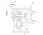
- FIG. 5 is a block diagram schematically showing the overall configuration of the superconducting cable cooling system 100 according to the second embodiment.
- symbol is attached
- the superconducting cable cooling system 100 is characterized in that a single Brayton cycle refrigerator 6 can cool a plurality of superconducting cables, namely the superconducting cable 1a and the superconducting cable 1b.
- Each of the superconducting cables 1a and 1b is provided with circulation pumps 5a and 5b, heat exchangers 17a and 17b, flow rate sensors 8a and 8b, reservoir tanks 2a and 2b, and independent circulation paths 9a and 9b are formed. Yes. Since the circulation paths 9a and 9b are independent of each other, the pressure, the flow rate, and the like are individually set and can be controlled in an independent state.
- Both the heat exchange units 17a and 17b are installed in a common cooling space 15 provided in the heat exchange unit 14.
- the Brayton cycle heat exchange unit 13 is also installed in the cooling space 15 and is filled with liquefied gas.
- the liquefied gas filled in the cooling space 15 is cooled to a predetermined temperature by controlling the Brayton cycle refrigerator 6 by the control unit 50.
- the refrigerant flowing through the circulation paths 9a and 9b is cooled by storing heat in the liquefied gas filled in the cooling space 15 in the heat exchange portions 17a and 17b, respectively, and the outlet temperature of the heat exchange portions 17a and 17b is cooled in the cooling space 15. It is determined by the temperature of the filled liquefied gas. Accordingly, the temperature of the liquefied gas is controlled to a predetermined temperature by controlling the Brayton cycle refrigerator 6 based on the temperature detected by the temperature sensor 7, so that the refrigerant temperature at the inlets of the superconducting cable 1a and the superconducting cable 1b. Are the same and have a predetermined temperature.
- the amount of heat generated in the superconducting cable 1a is P ca [W]
- the amount of heat generated in the superconducting cable 1b is P cb [W]
- the amount of heat generated in the circulation pump 5a is P pa “W”
- the circulation pump 5b is P pa “W”
- the heat generation time of the superconducting cable 1a is t 1a [seconds]
- the heat generation time of the superconducting cable 1b is t 1b [seconds]
- the operation times of the circulation pumps 5a and 5b are t p [seconds].
- the control part 50 can control the cooling temperature in the superconducting cables 1a and 1b easily and stably by operating the Brayton cycle refrigerator 6 based on the temperature detected by the temperature sensor 7.
- FIG. 6 is a block diagram schematically showing the overall configuration of the superconducting cable cooling system 100 according to the third embodiment.
- symbol is attached
- the superconducting cables 1a and 1b may be connected in series to increase the distance.
- independent circulation paths 9a and 9b are provided so as to correspond to the respective superconducting cables.
- the superconducting cables 1a and 1b adjacent to each other by one Brayton cycle refrigerator 6 are configured to be cooled.
- the superconducting cables 1a and 1b are independently formed with circulation paths 9a and 9b, which respectively include circulation pumps 5a and 5b, heat exchange portions 17a and 17b, flow rate sensors 8a and 8b, and reservoir tanks 2a and 2b.
- circulation paths 9a and 9b which respectively include circulation pumps 5a and 5b, heat exchange portions 17a and 17b, flow rate sensors 8a and 8b, and reservoir tanks 2a and 2b.
- Both the heat exchange parts 17a and 17b are installed in the cooling space 15 of the same heat exchange unit 14.
- the Brayton cycle heat exchange unit 13 is also installed in the cooling space 15 of the heat exchange unit 14 and is filled with liquefied gas.
- the liquefied gas is cooled to a predetermined temperature by controlling the Brayton cycle refrigerator 6 by the control unit 50.
- the refrigerant flowing through the circulation paths 9a and 9b is cooled in the form of storing heat in the liquefied gas filled in the cooling space 15 in the refrigerant heat exchanges 4a and 4b, respectively, and the outlet temperatures of the heat exchange units 17a and 17b are the heat exchange units 14 It is determined by the temperature of the liquefied gas in the cooling space 15. Therefore, by controlling the temperature of the liquefied gas in the cooling space 15 of the heat exchange unit 14 to a predetermined temperature by controlling the Brayton cycle refrigerator 6 based on the temperature detected by the temperature sensor 7, the superconducting cable 1a The refrigerant temperature at the entrance of the superconducting cable 1b is the same and is a predetermined temperature.
- the amount of heat generated in the superconducting cable 1a is P ca [W]
- the amount of heat generated in the superconducting cable 1b is P cb [W]
- the amount of heat generated in the circulation pump 5a is P pa “W”
- the circulation pump 5b is P pa “W”
- the heat generation time of the superconducting cable 1a is t 1a [seconds]
- the heat generation time of the superconducting cable 1b is t 1b [seconds]
- the operation times of the circulation pumps 5a and 5b are t p [seconds].
- independent circulation paths 9a and 9b are formed in the superconducting cables 1a and 1b that are connected in series as described above and arranged adjacent to each other.
- FIG. 7 is a block diagram schematically showing the overall configuration of the superconducting cable cooling system 100 according to the fourth embodiment.
- symbol is attached
- the exhaust device 16 is attached to the heat exchange unit 14 so that the liquefied gas filled in the cooling space 15 can be cooled under reduced pressure.
- the volume of the liquefied gas filled in the cooling space 15 is V [m3]
- the pressure is p [Pa]
- the temperature is T [K]
- the gas constant of the liquefied gas is R
- p ⁇ V R ⁇ T (14)
- the temperature T can be lowered by lowering the pressure p while keeping the volume V constant.
- the cooling space 15 is decompressed by the exhaust device 16, so that the cooling space 15 The filled liquefied gas can be cooled. Therefore, the superconducting cable cooling system 100 having higher reliability can be realized.
- the exhaust apparatus 16 can be attached also to the heat exchange unit 14 in the said various Example, and can obtain the same effect.
- FIG. 8 is a block diagram schematically showing the overall configuration of the superconducting cable cooling system 100 according to the fifth embodiment.
- FIG. 9 is a graph showing the heat generated by the refrigerant and the temperature distribution of the refrigerant in each part of the circulation path 9 of the superconducting cable cooling system according to the fifth embodiment.
- the horizontal axis indicates the distance from the reference position (the refrigerant outlet of the superconducting cable 1)
- the vertical axis in FIG. 9 (a) is the heat generation at each point
- the temperature at each point is shown.
- symbol is attached
- a plurality of heat exchanging parts 17 a and 17 b are provided on the circulation path 9.
- the heat exchange units 17 a and 17 b are provided on the circulation path 9 so that the circulation pump 5 is disposed therebetween.
- the temperature of the refrigerant flowing through the circulation path 9 rises by ⁇ Tc by receiving the amount of heat Pc in the superconducting cable 1. Then, after the refrigerant is cooled by the heat exchanging portion 17a, the temperature rises by ⁇ Tp when the circulation pump 5 receives the heat quantity Pp. And it is pumped by the circulation pump 5 to the heat exchange part 17b, cooled again, and returns to the initial inlet temperature.
- the heat exchange units 17a and 17b provided before and after the circulation pump 5 are cooled in two stages. Therefore, since the refrigerant cooled in advance in the heat exchanging portion 17a can be supplied to the circulation pump 5, a large margin for heat generation in the circulation pump 5 can be ensured.
- the Brayton cycle heat exchange unit 13 and the heat exchange units 17a and 17b for cooling the refrigerant are installed in the cooling space 15 of the heat exchange unit 14, and the circulation pump 5 is installed in the heat exchange unit.
- coolant entrance / exit in the superconducting cable 1 can be taken large.
- coolant in the circulation path 9 can be decreased, and the circulation pump 5 and the Brayton cycle refrigerator 6 can be reduced in size.
- the present embodiment is applied to the second and third embodiments, the same effect can be obtained.
- the present invention is applicable to a superconducting cable cooling system for cooling a superconducting cable used for power transmission / distribution to a cryogenic temperature.
Landscapes
- Engineering & Computer Science (AREA)
- Physics & Mathematics (AREA)
- Thermal Sciences (AREA)
- Mechanical Engineering (AREA)
- General Engineering & Computer Science (AREA)
- Chemical & Material Sciences (AREA)
- Combustion & Propulsion (AREA)
- Superconductors And Manufacturing Methods Therefor (AREA)
- Containers, Films, And Cooling For Superconductive Devices (AREA)
Abstract
Description
冷却システム100は、冷却対象として高温超電導体からなる超電導ケーブル1を有しており、該超電導ケーブル1の冷却用冷媒として液体窒素を用いている。超電導ケーブル1を冷却した冷媒は、一旦リザーバータンク2に貯留される。リザーバータンク2では、冷媒が加圧装置3によって所定圧力値に加圧されて貯留されている。この所定圧力値は、リザーバータンク2に設けられた圧力センサ4によって検出した圧力値を、図不示の加圧装置3のコントローラが取得し、該取得した圧力値が所定値になるように加圧装置3をフィードバック制御することによって維持されている。
図1は第1実施例に係る超電導ケーブル冷却システム100の全体構成を概略的に示す構成図である。尚、図10を参照して説明した背景技術と共通する箇所については、共通の符号を付すこととし、細部については適宜説明を省略することとする。
ΔTC=(PC×t1+PP×tP)/(m×C×tp) (1)
で求められる。ここで冷却システム100全体における発熱量Q[J]は
Q=(PC×t1+PP×tP) (2)
である。この発熱量Qは冷却空間15に充填された液化ガスに蓄熱され、仮に液化ガスが冷凍機6によって冷却されないと仮定した場合、液化ガスの温度は次式により算出される温度ΔTだけ上昇することとなる。
ΔT=Q/(M×C) (3)
従って、液化ガスの温度上昇をΔT=0[K]にするためには、発熱量Qに相当する熱量を冷却空間15に充填された液化ガスから取り去ればよいので、ブレイトンサイクル冷凍機6の冷却能力Pbを次式
Pb=Q/tP (4)
になるように制御するとよい。制御部50は、このように(4)式により求められる冷却能力Pbを発揮するように冷凍機6を制御することにより、液化ガスの温度上昇をΔT=0[K]にし、超電導ケーブル1の冷却を安定的に行うことが可能となる。
tP=t1+t2
であるため、ブレイトンサイクル冷凍機6の冷却能力Pbが次式
Pb×(t1+t2)=(PP+PC1)×t1+(PP+PC2)×t2 (5)
になるように制御するとよい。
Q1=(PC1+PP)×t1 (6)
により求められる。この発熱量Q1は冷却空間15に充填された液化ガスに蓄熱されて冷媒温度を上昇させるが、冷凍機6によって液化ガスが冷却される。そのため、期間t1における温度変化ΔT1は、
ΔT1=(PC1+PP-Pb)×t1/(M×C) (7)
と算出される。そして期間t2では、冷凍機6の冷却能力Pbが(5)式により制御されているので、ΔT1上昇して初期温度T0に戻る。尚、このΔT1は、t2を用いて次式のように算出することもできる。
ΔT1=(PC2+PP-Pb)×t2/(M×C) (8)
TC=Ts+ΔTC (9)
となる。ここで、ΔTCは熱交換ユニット14内の熱交換部4の熱交換効率で決まる温度差であり、所定値となるように熱交換ユニット14や熱交換部4の構成や材料等を選択するとよい。
図5は第2実施例に係る超電導ケーブル冷却システム100の全体構成を概略的に示す構成図である。尚、実施例1と同一の構成には同一の符号を付し、重複する説明は適宜省略することとする。
Q=Pca×t1a+Pcb×t1b+Ppa×tp+Ppb×tp (10)
により算出される。この合計熱量を冷却空間15に充填された液化ガスに蓄熱し、ブレイトンサイクル冷凍機6で取り去ればよい。そのため、ブレイトンサイクル冷凍機6の冷却能力Pb[W]は
Pb=Q/tp (11)
となるように制御されればよい。このように、ブレイトンサイクル冷凍機6の冷却能力Pbは超電導ケーブル1a及び1b、循環ポンプ5a及び5bにおける合計熱量で算出されるので、超電導ケーブル1a及び1bにおける発熱の時間的な変動の影響を受けることはない。
続いて図6を参照して、第3実施例に係る超電導ケーブル冷却システム100について説明する。図6は第3実施例に係る超電導ケーブル冷却システム100の全体構成を概略的に示す構成図である。尚、上記第1実施例と同一の構成には同一の符号を付し、重複する説明は適宜省略することとする。
Q=Pca×t1a+Pcb×t1b+Ppa×tp+Ppb×tp (12)
により算出される。この合計熱量を冷却空間15に充填された液化ガスに蓄熱し、ブレイトンサイクル冷凍機6で取り去ればよい。そのため、ブレイトンサイクル冷凍機6の冷却能力Pb[W]は
Pb=Q/tp (13)
となるように制御されればよい。このように、ブレイトンサイクル冷凍機6の冷却能力Pbは超電導ケーブル1a及び1b、循環ポンプ5a及び5bにおける合計熱量で算出されるので、超電導ケーブル1a及び1bにおける発熱の時間的な変動の影響を受けることはない。
次に図7を参照して、第4実施例に係る超電導ケーブル冷却システム100について説明する。図7は第4実施例に係る超電導ケーブル冷却システム100の全体構成を概略的に示す構成図である。尚、上記第1実施例と同一の構成には同一の符号を付し、重複する説明は適宜省略することとする。
p×V=R×T (14)
の関係が成立する。ここで、体積Vを一定としつつ圧力pを下げることで、温度Tを下げることができる。
次に図8及び図9を参照して、第5実施例に係る超電導ケーブル冷却システム100について説明する。図8は第5実施例に係る超電導ケーブル冷却システム100の全体構成を概略的に示す構成図である。また図9は第5実施例に係る超電導ケーブル冷却システムの循環経路9の各部で冷媒が受け取る発熱、及び冷媒の温度分布を示すグラフ図である。尚、図9では、横軸は基準位置(超電導ケーブル1の冷媒出口)からの距離を示しており、図9(a)の縦軸は各地点における発熱、図9(b)の縦軸は各地点における温度を示している。尚、上記第1実施例と同一の構成には同一の符号を付し、重複する説明は適宜省略することとする。
PP=k×m×p (15)
と求められる。ここで、kは比例乗数である。そのため、流量が減少すると圧力損失も減少し、循環ポンプ5の加圧量も減少する。従って、循環ポンプ5の発熱PPは大幅に減少し、ブレイトンサイクル冷凍機6の能力を低減することができる。
Claims (7)
- 超電導ケーブルの冷却用に使用された冷媒を、循環ポンプで熱交換部に圧送して冷凍機により冷却した後、前記超電導ケーブルに供給して循環経路を形成することにより、前記超電導ケーブルを冷却する超電導ケーブル冷却システムにおいて、
前記熱交換部と前記冷凍機とを熱交換させるための液化ガスが充填された冷却空間を有する熱交換ユニットと、
前記循環経路における冷媒の流量を検出するための流量検出手段と、
前記熱交換ユニットに充填された液化ガスの温度を検出するための温度検出手段と、
前記流量検出手段によって検出された流量、及び前記温度検出手段によって検出された温度に基づいて、前記熱交換ユニットに充填された液化ガスの温度が所定値になるように前記冷凍機を制御する制御部と
を備えたことを特徴とする超電導ケーブル冷却システム。 - 前記冷凍機は、前記冷却空間内に配置されたブレイトンサイクル熱交換部を有するブレイトンサイクル冷凍機であることを特徴とする請求項1に記載の超電導ケーブル冷却システム。
- 前記循環経路には、該循環経路を流れる冷媒を所定圧力に加圧して貯留するリザーバータンクが接続されていることを特徴とする請求項1又は2に記載の超電導ケーブル冷却システム。
- 前記超電導ケーブルを複数備える場合、前記循環経路は前記超電導ケーブルの各々に対応してそれぞれ形成されており、
前記循環経路の各々における前記熱交換部は、単一の前記冷却空間内に配置されていることを特徴とする請求項1から3のいずれか一項に記載の超電導ケーブル冷却システム。 - 前記複数の超電導ケーブルが互いに直列に接続されている場合に、前記複数の超電導ケーブルのうち隣り合う超電導ケーブルに対応して形成された循環経路に含まれる熱交換部が、前記冷却空間内に配置されていることを特徴とする請求項4に記載の超電導ケーブル冷却システム。
- 前記熱交換ユニットの冷却空間内に充填された液化ガスを減圧するための減圧手段を更に備えたことを特徴とする請求項1から5のいずれか一項に記載の超電導ケーブル冷却システム。
- 前記熱交換部は前記循環経路に複数設けられており、前記循環ポンプは前記複数の熱交換部のいずれかの間に設けられていることを特徴とする請求項1から6のいずれか一項に記載の超電導ケーブル冷却システム。
Priority Applications (6)
| Application Number | Priority Date | Filing Date | Title |
|---|---|---|---|
| BR112013013916-1A BR112013013916B1 (pt) | 2011-02-25 | 2011-02-25 | Sistema de resfriamento de cabo supercondutor |
| JP2013500796A JP5665963B2 (ja) | 2011-02-25 | 2011-02-25 | 超電導ケーブル冷却システム |
| CH01452/13A CH706385B1 (fr) | 2011-02-25 | 2011-02-25 | Système de refroidissement d'un câble supraconducteur. |
| CN201180060960.1A CN103262179B (zh) | 2011-02-25 | 2011-02-25 | 超导电电缆冷却系统 |
| PCT/JP2011/054312 WO2012114507A1 (ja) | 2011-02-25 | 2011-02-25 | 超電導ケーブル冷却システム |
| US13/973,914 US9218899B2 (en) | 2011-02-25 | 2013-08-22 | Superconducting cable cooling system |
Applications Claiming Priority (1)
| Application Number | Priority Date | Filing Date | Title |
|---|---|---|---|
| PCT/JP2011/054312 WO2012114507A1 (ja) | 2011-02-25 | 2011-02-25 | 超電導ケーブル冷却システム |
Related Child Applications (1)
| Application Number | Title | Priority Date | Filing Date |
|---|---|---|---|
| US13/973,914 Continuation US9218899B2 (en) | 2011-02-25 | 2013-08-22 | Superconducting cable cooling system |
Publications (1)
| Publication Number | Publication Date |
|---|---|
| WO2012114507A1 true WO2012114507A1 (ja) | 2012-08-30 |
Family
ID=46720323
Family Applications (1)
| Application Number | Title | Priority Date | Filing Date |
|---|---|---|---|
| PCT/JP2011/054312 Ceased WO2012114507A1 (ja) | 2011-02-25 | 2011-02-25 | 超電導ケーブル冷却システム |
Country Status (6)
| Country | Link |
|---|---|
| US (1) | US9218899B2 (ja) |
| JP (1) | JP5665963B2 (ja) |
| CN (1) | CN103262179B (ja) |
| BR (1) | BR112013013916B1 (ja) |
| CH (1) | CH706385B1 (ja) |
| WO (1) | WO2012114507A1 (ja) |
Cited By (8)
| Publication number | Priority date | Publication date | Assignee | Title |
|---|---|---|---|---|
| CN103500968A (zh) * | 2013-10-23 | 2014-01-08 | 张建锋 | 一种双向抽气式电缆冷却器 |
| JP2014070747A (ja) * | 2012-09-27 | 2014-04-21 | Sumitomo Electric Ind Ltd | 冷却システム |
| JP2014199745A (ja) * | 2013-03-29 | 2014-10-23 | 株式会社前川製作所 | 超電導ケーブル用冷却システム |
| JP2016524117A (ja) * | 2013-07-04 | 2016-08-12 | メッサー グループ ゲーエムベーハーMesser Group Gmbh | 冷却回路において過冷却液によって被冷却体を冷却する装置 |
| JP2016170928A (ja) * | 2015-03-12 | 2016-09-23 | 株式会社前川製作所 | 超電導体の冷却装置 |
| JP2020507051A (ja) * | 2017-02-08 | 2020-03-05 | リンデ・アクツィエンゲゼルシャフトLinde Aktiengesellschaft | 負荷を冷却する方法および装置ならびに相応する装置と負荷とを備えたシステム |
| JP2021103729A (ja) * | 2019-12-25 | 2021-07-15 | 株式会社前川製作所 | 超電導限流器の冷却システム、超電導限流器及び超電導限流器の冷却システムの制御方法 |
| WO2025084580A1 (ko) * | 2023-10-19 | 2025-04-24 | 제이에스이엔지 주식회사 | 전기차 충전 케이블 냉각 시스템 |
Families Citing this family (19)
| Publication number | Priority date | Publication date | Assignee | Title |
|---|---|---|---|---|
| CN103458664A (zh) * | 2013-09-06 | 2013-12-18 | 重庆创思特科技有限公司 | 循环液式自传感适温电路板保护装置 |
| CN103500950B (zh) * | 2013-10-23 | 2015-12-30 | 国网浙江省电力公司嵊泗县供电公司 | 一种方形抽气式电缆冷却器 |
| CN103633571B (zh) * | 2013-10-23 | 2015-11-25 | 吴平芳 | 一种抽气式电缆冷却装置 |
| CN103500951B (zh) * | 2013-10-23 | 2015-08-05 | 黄三甦 | 一种方形双向抽气式电缆冷却装置 |
| CN103500970B (zh) * | 2013-10-23 | 2016-04-13 | 汪清明 | 一种方形双向抽气式电缆冷却器 |
| CN104064280A (zh) * | 2014-06-13 | 2014-09-24 | 苏州华徕光电仪器有限公司 | 一种超导电缆循环冷却系统 |
| CN104064279A (zh) * | 2014-06-13 | 2014-09-24 | 苏州华徕光电仪器有限公司 | 一种冷绝缘超导电缆的冷却系统 |
| CN107240454A (zh) * | 2017-06-08 | 2017-10-10 | 北汽福田汽车股份有限公司 | 电力电缆、电力电缆总成及电动汽车 |
| WO2019147563A1 (en) * | 2018-01-23 | 2019-08-01 | The Tisdale Group | Liquid nitrogen-based cooling system |
| CN109297254A (zh) * | 2018-09-10 | 2019-02-01 | 成都深冷液化设备股份有限公司 | 以低温制冷机组为冷源的充电电缆气体循环冷却方法 |
| CN110828060B (zh) * | 2019-11-12 | 2024-09-27 | 国网上海市电力公司 | 用于高温超导电缆终端的电动导轮控制系统及其运行方法 |
| CN110848563B (zh) * | 2019-11-18 | 2021-07-16 | 中国科学院理化技术研究所 | 一种超导能源管道的运行控制系统 |
| CN111271927A (zh) * | 2020-03-16 | 2020-06-12 | 中建环能建筑工程有限公司 | 电缆自动降温系统 |
| EP4153901B1 (en) * | 2020-05-20 | 2024-04-24 | L'Air Liquide, Société Anonyme pour l'Etude et l'Exploitation des Procédés Georges Claude | Method for cooling a system in the 120k to 200k range |
| EP3943833B1 (en) * | 2020-07-23 | 2025-09-03 | Linde GmbH | Method for cooling a superconducting cable |
| CN112415302B (zh) * | 2020-10-27 | 2022-01-18 | 西安电子科技大学 | 一种传导冷却高温超导电缆的运行与测试装置及方法 |
| CN112614621B (zh) * | 2020-12-10 | 2023-06-09 | 深圳供电局有限公司 | 一种超导电缆制冷系统 |
| CN115773609B (zh) * | 2022-11-30 | 2025-08-05 | 国网浙江省电力有限公司电力科学研究院 | 一种高温超导电缆冷却系统的温度控制方法 |
| CN116792988B (zh) * | 2023-06-21 | 2025-12-19 | 广州极导能源科技有限责任公司 | 海上集中式制冷系统 |
Citations (6)
| Publication number | Priority date | Publication date | Assignee | Title |
|---|---|---|---|---|
| JPH08152204A (ja) * | 1994-11-30 | 1996-06-11 | Hitachi Ltd | 空気調和機及びその運転方法 |
| WO1999062127A1 (en) * | 1998-05-22 | 1999-12-02 | Sumitomo Electric Industries, Ltd. | Method and device for cooling superconductor |
| JP2004233010A (ja) * | 2003-01-31 | 2004-08-19 | Daikin Ind Ltd | ヒートポンプ式給湯機 |
| JP2006012654A (ja) * | 2004-06-28 | 2006-01-12 | Furukawa Electric Co Ltd:The | 超電導電力機器用冷却システム |
| JP2006052921A (ja) * | 2004-08-16 | 2006-02-23 | Mayekawa Mfg Co Ltd | スラッシュ冷媒を利用した冷却方法及び装置、並びに超電導限流器 |
| JP2007023966A (ja) * | 2005-07-20 | 2007-02-01 | Denso Corp | エジェクタおよびエジェクタ式サイクル |
Family Cites Families (10)
| Publication number | Priority date | Publication date | Assignee | Title |
|---|---|---|---|---|
| GB1109811A (en) * | 1965-08-24 | 1968-04-18 | British Insulated Callenders | Improvements in electric cable installations |
| CH657144A5 (de) | 1983-05-04 | 1986-08-15 | Ciba Geigy Ag | Verfahren zur umwandlung schwerloeslicher salze anionischer farbstoffe und optischer aufheller in leichter loesliche salze mittels kationenaustausch. |
| JP2666664B2 (ja) * | 1992-05-29 | 1997-10-22 | 石川島播磨重工業株式会社 | 超流動ヘリウムを製造する方法及び装置 |
| IT1269458B (it) * | 1994-01-24 | 1997-04-01 | N R Dev L T D | Metodo e apparato per l'assorbimento di calore e il mantenimento in condizioni ottimali a temperatura prefissata di prodotti freschi |
| JPH11325630A (ja) * | 1998-05-19 | 1999-11-26 | Ishikawajima Harima Heavy Ind Co Ltd | ヘリウム液化冷凍装置 |
| JP2004316971A (ja) * | 2003-04-14 | 2004-11-11 | Ishikawajima Harima Heavy Ind Co Ltd | ヘリウム液化冷凍装置 |
| JP2005003314A (ja) * | 2003-06-13 | 2005-01-06 | Ishikawajima Harima Heavy Ind Co Ltd | 超電導電磁石冷却装置 |
| CN100507403C (zh) * | 2005-05-24 | 2009-07-01 | 株式会社电装 | 喷射器和喷射循环装置 |
| DE102006024211A1 (de) | 2005-05-24 | 2007-01-25 | Denso Corp., Kariya | Ejektorpumpe und Ejektorpumpenkreisvorrichtung |
| US7885074B2 (en) * | 2009-06-25 | 2011-02-08 | International Business Machines Corporation | Direct jet impingement-assisted thermosyphon cooling apparatus and method |
-
2011
- 2011-02-25 BR BR112013013916-1A patent/BR112013013916B1/pt not_active IP Right Cessation
- 2011-02-25 WO PCT/JP2011/054312 patent/WO2012114507A1/ja not_active Ceased
- 2011-02-25 JP JP2013500796A patent/JP5665963B2/ja active Active
- 2011-02-25 CH CH01452/13A patent/CH706385B1/fr not_active IP Right Cessation
- 2011-02-25 CN CN201180060960.1A patent/CN103262179B/zh active Active
-
2013
- 2013-08-22 US US13/973,914 patent/US9218899B2/en not_active Expired - Fee Related
Patent Citations (6)
| Publication number | Priority date | Publication date | Assignee | Title |
|---|---|---|---|---|
| JPH08152204A (ja) * | 1994-11-30 | 1996-06-11 | Hitachi Ltd | 空気調和機及びその運転方法 |
| WO1999062127A1 (en) * | 1998-05-22 | 1999-12-02 | Sumitomo Electric Industries, Ltd. | Method and device for cooling superconductor |
| JP2004233010A (ja) * | 2003-01-31 | 2004-08-19 | Daikin Ind Ltd | ヒートポンプ式給湯機 |
| JP2006012654A (ja) * | 2004-06-28 | 2006-01-12 | Furukawa Electric Co Ltd:The | 超電導電力機器用冷却システム |
| JP2006052921A (ja) * | 2004-08-16 | 2006-02-23 | Mayekawa Mfg Co Ltd | スラッシュ冷媒を利用した冷却方法及び装置、並びに超電導限流器 |
| JP2007023966A (ja) * | 2005-07-20 | 2007-02-01 | Denso Corp | エジェクタおよびエジェクタ式サイクル |
Cited By (13)
| Publication number | Priority date | Publication date | Assignee | Title |
|---|---|---|---|---|
| JP2014070747A (ja) * | 2012-09-27 | 2014-04-21 | Sumitomo Electric Ind Ltd | 冷却システム |
| JP2014199745A (ja) * | 2013-03-29 | 2014-10-23 | 株式会社前川製作所 | 超電導ケーブル用冷却システム |
| JP2016524117A (ja) * | 2013-07-04 | 2016-08-12 | メッサー グループ ゲーエムベーハーMesser Group Gmbh | 冷却回路において過冷却液によって被冷却体を冷却する装置 |
| CN103500968A (zh) * | 2013-10-23 | 2014-01-08 | 张建锋 | 一种双向抽气式电缆冷却器 |
| CN103500968B (zh) * | 2013-10-23 | 2015-10-14 | 国网山东省电力公司日照供电公司 | 一种双向抽气式电缆冷却器 |
| US10030919B2 (en) | 2015-03-12 | 2018-07-24 | Mayekawa Mfg. Co., Ltd. | Cooling apparatus for superconductor |
| JP2016170928A (ja) * | 2015-03-12 | 2016-09-23 | 株式会社前川製作所 | 超電導体の冷却装置 |
| JP2020507051A (ja) * | 2017-02-08 | 2020-03-05 | リンデ・アクツィエンゲゼルシャフトLinde Aktiengesellschaft | 負荷を冷却する方法および装置ならびに相応する装置と負荷とを備えたシステム |
| JP2021103729A (ja) * | 2019-12-25 | 2021-07-15 | 株式会社前川製作所 | 超電導限流器の冷却システム、超電導限流器及び超電導限流器の冷却システムの制御方法 |
| JP7579633B2 (ja) | 2019-12-25 | 2024-11-08 | 株式会社前川製作所 | 超電導限流器の冷却システム、超電導限流器及び超電導限流器の冷却システムの制御方法 |
| WO2025084580A1 (ko) * | 2023-10-19 | 2025-04-24 | 제이에스이엔지 주식회사 | 전기차 충전 케이블 냉각 시스템 |
| KR20250056524A (ko) * | 2023-10-19 | 2025-04-28 | 제이에스이엔지 주식회사 | 전기차 충전 케이블 냉각 시스템 |
| KR102893746B1 (ko) * | 2023-10-19 | 2025-12-01 | 이브이엔솔 주식회사 | 전기차 충전 케이블 냉각 시스템 |
Also Published As
| Publication number | Publication date |
|---|---|
| US9218899B2 (en) | 2015-12-22 |
| CN103262179A (zh) | 2013-08-21 |
| BR112013013916B1 (pt) | 2020-01-07 |
| JPWO2012114507A1 (ja) | 2014-07-07 |
| CH706385B1 (fr) | 2015-05-15 |
| BR112013013916A2 (pt) | 2016-09-13 |
| JP5665963B2 (ja) | 2015-02-04 |
| US20130333912A1 (en) | 2013-12-19 |
| CN103262179B (zh) | 2016-08-31 |
Similar Documents
| Publication | Publication Date | Title |
|---|---|---|
| JP5665963B2 (ja) | 超電導ケーブル冷却システム | |
| JP6445752B2 (ja) | 超電導磁石装置 | |
| Dietrich et al. | High-power Stirling-type pulse tube cryocooler: Observation and reduction of regenerator temperature-inhomogeneities | |
| US10030919B2 (en) | Cooling apparatus for superconductor | |
| Penswick et al. | High-capacity and efficiency Stirling cycle cryocooler | |
| Garg et al. | Effect of Porosity of the regenerator on the performance of a miniature Stirling cryocooler | |
| CN1942979B (zh) | 低温电缆的循环冷却系统 | |
| Deng et al. | Development of the double two-phase thermosyphon loops used in low temperature Stirling refrigerator | |
| EP1931926B1 (en) | Refrigeration system for superconducting devices | |
| CN103782353B (zh) | 用于冷却装置的设备和方法 | |
| JP5959062B2 (ja) | 電流リード装置 | |
| Chen et al. | RELIABILITY TEST OF A 1‐kW PULSE TUBE CRYOCOOLER FOR HTS CABLE APPLICATION | |
| Liu et al. | Investigation on the thermal performance of liquid neon pulsating heat pipe with different bending angles | |
| Zhang et al. | Experimental and numerical study of a heat-driven cascade-looped thermoacoustic cryocooler working at 77 K | |
| JP2008116171A (ja) | ガス伝熱装置とこれを用いた超電導装置 | |
| Xu et al. | The dynamic performance of a compact LN2 depressurization cryocooling system | |
| JP5087028B2 (ja) | 極低温冷却装置 | |
| Qiu et al. | Experimental study on dynamic characteristics of a joule-Thomson cryocooler working at liquid helium temperature | |
| RU2352009C2 (ru) | Циркуляционная система охлаждения криогенного кабеля | |
| Haid | Helium pot system for maintaining sample temperature after cryocooler deactivation | |
| JP4046060B2 (ja) | 極低温ケーブルの循環冷却システム | |
| Evdulov et al. | Experimental Investigations of a Thermoelectric Heat Exchanger with Heat Bridges | |
| Johnson et al. | Installation of pulse tube cryocoolers for cooling of HTS cable | |
| Willems et al. | Closed loop cooling systems for HTS applications | |
| Caillaud et al. | Two Refrigeration Systems Installed for the Tokamak at the Institute for Plasma Research, Ahmedabad, India |
Legal Events
| Date | Code | Title | Description |
|---|---|---|---|
| 121 | Ep: the epo has been informed by wipo that ep was designated in this application |
Ref document number: 11859201 Country of ref document: EP Kind code of ref document: A1 |
|
| ENP | Entry into the national phase |
Ref document number: 2013500796 Country of ref document: JP Kind code of ref document: A |
|
| WWE | Wipo information: entry into national phase |
Ref document number: 2013001890 Country of ref document: CL |
|
| WWE | Wipo information: entry into national phase |
Ref document number: 10201300001452 Country of ref document: CH |
|
| NENP | Non-entry into the national phase |
Ref country code: DE |
|
| 122 | Ep: pct application non-entry in european phase |
Ref document number: 11859201 Country of ref document: EP Kind code of ref document: A1 |
|
| REG | Reference to national code |
Ref country code: BR Ref legal event code: B01A Ref document number: 112013013916 Country of ref document: BR |
|
| ENP | Entry into the national phase |
Ref document number: 112013013916 Country of ref document: BR Kind code of ref document: A2 Effective date: 20130605 |