WO2012114505A1 - 車両の制御装置 - Google Patents
車両の制御装置 Download PDFInfo
- Publication number
- WO2012114505A1 WO2012114505A1 PCT/JP2011/054279 JP2011054279W WO2012114505A1 WO 2012114505 A1 WO2012114505 A1 WO 2012114505A1 JP 2011054279 W JP2011054279 W JP 2011054279W WO 2012114505 A1 WO2012114505 A1 WO 2012114505A1
- Authority
- WO
- WIPO (PCT)
- Prior art keywords
- engine
- air conditioning
- fuel
- control unit
- start control
- Prior art date
- Legal status (The legal status is an assumption and is not a legal conclusion. Google has not performed a legal analysis and makes no representation as to the accuracy of the status listed.)
- Ceased
Links
Images



Classifications
-
- F—MECHANICAL ENGINEERING; LIGHTING; HEATING; WEAPONS; BLASTING
- F02—COMBUSTION ENGINES; HOT-GAS OR COMBUSTION-PRODUCT ENGINE PLANTS
- F02D—CONTROLLING COMBUSTION ENGINES
- F02D29/00—Controlling engines, such controlling being peculiar to the devices driven thereby, the devices being other than parts or accessories essential to engine operation, e.g. controlling of engines by signals external thereto
- F02D29/02—Controlling engines, such controlling being peculiar to the devices driven thereby, the devices being other than parts or accessories essential to engine operation, e.g. controlling of engines by signals external thereto peculiar to engines driving vehicles; peculiar to engines driving variable pitch propellers
-
- B—PERFORMING OPERATIONS; TRANSPORTING
- B60—VEHICLES IN GENERAL
- B60H—ARRANGEMENTS OF HEATING, COOLING, VENTILATING OR OTHER AIR-TREATING DEVICES SPECIALLY ADAPTED FOR PASSENGER OR GOODS SPACES OF VEHICLES
- B60H1/00—Heating, cooling or ventilating devices
- B60H1/00642—Control systems or circuits; Control members or indication devices for heating, cooling or ventilating devices
- B60H1/00735—Control systems or circuits characterised by their input, i.e. by the detection, measurement or calculation of particular conditions, e.g. signal treatment, dynamic models
- B60H1/00764—Control systems or circuits characterised by their input, i.e. by the detection, measurement or calculation of particular conditions, e.g. signal treatment, dynamic models the input being a vehicle driving condition, e.g. speed
- B60H1/00778—Control systems or circuits characterised by their input, i.e. by the detection, measurement or calculation of particular conditions, e.g. signal treatment, dynamic models the input being a vehicle driving condition, e.g. speed the input being a stationary vehicle position, e.g. parking or stopping
-
- F—MECHANICAL ENGINEERING; LIGHTING; HEATING; WEAPONS; BLASTING
- F02—COMBUSTION ENGINES; HOT-GAS OR COMBUSTION-PRODUCT ENGINE PLANTS
- F02D—CONTROLLING COMBUSTION ENGINES
- F02D41/00—Electrical control of supply of combustible mixture or its constituents
- F02D41/02—Circuit arrangements for generating control signals
- F02D41/04—Introducing corrections for particular operating conditions
- F02D41/06—Introducing corrections for particular operating conditions for engine starting or warming up
- F02D41/062—Introducing corrections for particular operating conditions for engine starting or warming up for starting
- F02D41/064—Introducing corrections for particular operating conditions for engine starting or warming up for starting at cold start
-
- F—MECHANICAL ENGINEERING; LIGHTING; HEATING; WEAPONS; BLASTING
- F02—COMBUSTION ENGINES; HOT-GAS OR COMBUSTION-PRODUCT ENGINE PLANTS
- F02N—STARTING OF COMBUSTION ENGINES; STARTING AIDS FOR SUCH ENGINES, NOT OTHERWISE PROVIDED FOR
- F02N11/00—Starting of engines by means of electric motors
- F02N11/08—Circuits specially adapted for starting of engines
- F02N11/0814—Circuits specially adapted for starting of engines comprising means for controlling automatic idle-start-stop
- F02N11/0818—Conditions for starting or stopping the engine or for deactivating the idle-start-stop mode
- F02N11/0833—Vehicle conditions
- F02N11/084—State of vehicle accessories, e.g. air condition or power steering
-
- F—MECHANICAL ENGINEERING; LIGHTING; HEATING; WEAPONS; BLASTING
- F02—COMBUSTION ENGINES; HOT-GAS OR COMBUSTION-PRODUCT ENGINE PLANTS
- F02N—STARTING OF COMBUSTION ENGINES; STARTING AIDS FOR SUCH ENGINES, NOT OTHERWISE PROVIDED FOR
- F02N2200/00—Parameters used for control of starting apparatus
- F02N2200/08—Parameters used for control of starting apparatus said parameters being related to the vehicle or its components
- F02N2200/0806—Air condition state
Definitions
- the present invention relates to control of a vehicle capable of executing pre-air-conditioning that pre-air-conditions the vehicle interior before starting the vehicle system.
- Patent Document 1 discloses a vehicle capable of executing pre-air-conditioning that pre-air-conditions the vehicle interior before starting the vehicle system in accordance with a user's remote operation.
- an electric fan for cooling an air-conditioning condenser disposed in the engine compartment may be operated. Due to the operation of the electric fan, the temperature change in the engine compartment is different from that during natural standing (when the electric fan is not operated). Therefore, when the user gets on and starts the engine, if the same engine start control is performed when there is a pre-air conditioning execution history and when it is not, the engine startability may be deteriorated.
- the present invention has been made to solve the above-described problems, and an object of the present invention is to ensure engine startability in a vehicle capable of performing pre-air-conditioning that pre-air-conditions the vehicle interior before starting the vehicle system. That is.
- the control device controls a vehicle capable of executing pre-air conditioning that air-conditions the vehicle interior before starting the vehicle system.
- the vehicle includes an engine, an air-conditioning condenser that is disposed inside a housing chamber that houses the engine, and an electric fan for cooling the condenser.
- the control device includes a fan operating unit that operates the electric fan during execution of pre-air conditioning, and a start control unit that executes start control for starting the engine. When starting the engine, the start control unit changes the start control mode in accordance with the pre-air-conditioning execution history.
- the engine includes a fuel supply pipe disposed at a position cooled by the operation of the electric fan, and an injection valve for injecting fuel supplied from the fuel supply pipe to the engine.
- the start control unit changes the amount of fuel injected from the injection valve according to the execution history of pre-air conditioning.
- the start control unit increases the amount of fuel injected from the injection valve when there is a pre-air conditioning execution history as compared to when there is no pre-air conditioning execution history.
- the start control unit calculates a basic fuel amount based on the engine water temperature, and if there is no pre-air conditioning execution history, the basic fuel amount is injected from the injection valve, and the pre-air conditioning execution history If there is, a correction fuel amount larger than the basic fuel amount is injected from the injection valve.
- the start control unit changes the correction fuel amount based on the operation time of the electric fan during the pre-air conditioning execution period.
- the start control unit increases the corrected fuel amount as the operating time of the electric fan during the pre-air conditioning execution period is longer.
- the start control unit estimates the fuel temperature in the fuel supply pipe based on the operating time of the electric fan and the outside air temperature during the pre-air conditioning execution period, and increases the corrected fuel amount as the estimated fuel temperature is lower
- the start control unit estimates the fuel temperature to a lower value as the operating time of the electric fan is longer and the outside air temperature is lower.
- the startability of the engine can be ensured in a vehicle capable of executing pre-air-conditioning that air-conditions the vehicle interior before the vehicle system is started.
- FIG. 1 is an overall block diagram of a vehicle. It is a figure which shows the structure of an engine in detail. It is a functional block diagram of ECU. It is a figure which shows the correspondence of engine water temperature THw and basic fuel injection amount Fbase. It is a figure which shows the correspondence of fuel temperature THf and the correction coefficient K. It is a flowchart which shows the process sequence of ECU.
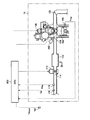
- FIG. 1 is an overall block diagram of a vehicle 1 according to an embodiment of the present invention.
- the vehicle 1 includes an engine 100, a radiator 200, a condenser 300, an electric fan 400, an air conditioning unit 500, an IG switch 600, a receiving device 700, and an ECU (Electronic Control Unit) 800.
- the vehicle to which the present invention can be applied is not limited to the vehicle 1 shown in FIG. 1 as long as it is an engine vehicle capable of performing pre-air conditioning described later.
- a vehicle so-called hybrid
- the use of the engine is not necessarily limited to vehicle travel, and may be for power generation, for example.
- the engine 100 is mounted inside an engine compartment 10 provided on the front side of the vehicle 1.
- Engine 100 is controlled by a control signal from ECU 800.
- the power of the engine 100 is transmitted to the wheels 11 via a speed reducer (not shown).
- the vehicle 1 is driven by the power of the engine 100.
- the engine compartment 10 is mounted with a radiator 200, a condenser 300, an electric fan 400, and an air conditioning unit 500.
- the radiator 200 is communicated with a water jacket (not shown) provided inside the engine 100 via pipes 210 and 220.
- the radiator 200 is a radiator for releasing heat of engine cooling water to the atmosphere.
- engine coolant circulates between the radiator 200 and the engine 100 (see arrow A). More specifically, the engine coolant that has absorbed the heat of the engine 100 is sent to the radiator 200, cooled by the radiator 200, and then returned to the engine 100 again. Thereby, engine 100 is cooled.
- the capacitor 300 is provided adjacent to the radiator 200 and communicates with the air conditioning unit 500 via the pipes 310 and 320.
- the condenser 300 is a condenser for releasing the heat of air-conditioning refrigerant gas into the atmosphere and condensing it.
- the air conditioning unit 500 is configured to include components (compressor, expansion valve, evaporator, etc.) necessary for realizing the refrigeration cycle in addition to the capacitor 300.
- the air conditioning refrigerant circulates between the condenser 300 and the air conditioning unit (see arrow B). More specifically, the refrigerant gas that has been pressurized and heated in the air conditioning unit 500 is sent to the condenser 300 to be condensed (liquefied), and then returned to the air conditioning unit 500 again. With such a refrigeration cycle, air conditioning (cooling) is performed in the passenger compartment.
- the electric fan 400 is provided in the vicinity of the radiator 200 and the condenser 300 inside the engine compartment 10. Electric fan 400 is controlled by a control signal from ECU 800. When electric fan 400 is operated, outside air is taken into engine compartment 10 through radiator 200 and condenser 300 (see arrow C). Thereby, outside air acts as cooling air, radiator 200 and condenser 300 are cooled, the inside of engine compartment 10 is scavenged, and the internal temperature of engine compartment 10 is lowered.
- the electric fan 400 may be provided separately for the capacitor 300 and the radiator 200.
- IG switch 600 is a switch for a user to input a vehicle system start request and stop request.
- vehicle system is an electrical device that is necessary for travel control of the vehicle 1.
- the receiving device 700 is a device for receiving a pre-air conditioning request signal transmitted from a remote control device (hereinafter also simply referred to as “remote controller”) 20.
- pre-air conditioning refers to control for operating the air-conditioning unit 500 and the electric fan 400 in response to a user request to air-condition the vehicle interior in advance before starting the vehicle system.
- the time before starting the vehicle system is before the Ready-ON state is entered. That is, the pre-air conditioning that is not directly related to the travel control is not executed by the vehicle system, but is executed before the Ready-ON state is entered.
- a pre-air conditioning request signal is transmitted from the remote controller 20.
- the receiving device 700 transmits the pre-air conditioning request signal to the ECU 800.
- the ECU 800 includes a CPU (Central Processing Unit) (not shown) and a memory, and is configured to execute a predetermined calculation process based on information stored in the memory and information from each sensor.
- CPU Central Processing Unit
- ECU800 will perform the pre-air conditioning by operating the air-conditioning unit 500 and the electric fan 400, if the pre-air-conditioning request signal is received from the receiving device 700.
- FIG. 2 is a diagram showing the configuration of the engine 100 in detail. Although one cylinder is illustrated in FIG. 2, the engine 100 is actually provided with a plurality of cylinders.
- air drawn from an air cleaner (not shown) is introduced into the combustion chamber 102 of the engine 100 through the intake pipe 110.
- the amount of air introduced into the combustion chamber 102 is adjusted by the operation amount (throttle opening) of the throttle valve 114.
- the throttle opening is controlled by a throttle motor 112 that operates based on a signal from the ECU 800.
- the injector 104 is opened by a control signal from the ECU 800 and injects fuel in the delivery pipe 105 toward the combustion chamber 102. Note that fuel may be directly injected from the injector 104 into the combustion chamber 102.
- An air-fuel mixture of air introduced from the intake pipe 110 and fuel injected from the injector 104 is ignited and burned using an ignition coil 106 controlled by a control signal from the ECU 800.
- the exhaust gas after the air-fuel mixture burns is exhausted to the atmosphere through the exhaust pipe 120.
- the ECU 800 receives signals from the outside air temperature sensor 107, the water temperature sensor 108, the air flow meter 116, and the intake air temperature sensor 118.
- the outside air temperature sensor 107 detects the outside air temperature (the temperature of the air outside the vehicle 1) THout.
- the water temperature sensor 108 detects engine water temperature (engine cooling water temperature) THw.
- the air flow meter 116 detects an intake air amount (air amount per unit time taken into the engine 100) Ga.
- Intake air temperature sensor 118 detects intake air temperature (temperature of air taken into engine 100) THa. Each of these sensors transmits a signal representing the detection result to ECU 800.
- the ECU 800 controls the throttle opening, ignition timing, and fuel injection amount by controlling the throttle motor 112, the ignition coil 106, and the injector 104 based on signals sent from the sensors.
- FIG. 3 is a functional block diagram of the ECU 800 when the pre-air conditioning control and the engine start control are executed. Each functional block shown in FIG. 3 may be realized by hardware or software.
- ECU 800 includes a pre-air conditioning control unit 810 and an engine start control unit 820.
- the pre-air conditioning control unit 810 receives the pre-air conditioning request signal from the receiving device 700, the pre-air conditioning unit 810 operates the air conditioning unit 500 to perform pre-air conditioning.
- the pre-air conditioning control unit 810 operates the electric fan 400 to cool the capacitor 300.
- the electric fan 400 does not necessarily have to be constantly operated, and may be operated intermittently.
- Engine start control unit 820 executes engine start control in response to a user start request (operation of IG switch 600).
- engine start control refers to control of throttle opening, ignition timing, fuel injection amount, etc. at the time of engine start.
- fuel injection control at the time of engine start will be described as an example of engine start control.
- the engine start control unit 820 includes a first determination unit 821, a correction coefficient calculation unit 822, a second determination unit 823, a basic injection amount calculation unit 824, and an injection amount determination unit 825.
- the first determination unit 821 determines whether or not pre-air conditioning is being executed. Since pre-air conditioning is executed by a user's remote operation, it is usually determined whether or not pre-air conditioning is being performed in a READY-OFF state (engine stopped state).
- the correction coefficient calculation unit 822 calculates the correction coefficient K when pre-air conditioning is being executed.
- the correction coefficient K is a coefficient for correcting a later-described basic fuel injection amount Fbase. A method for calculating the correction coefficient K will be described in detail later.
- second determination unit 823 determines whether the READY-OFF state has been switched to the READY-ON state (whether the user has performed a starting operation on IG switch 600). Or not).
- the basic injection amount calculation unit 824 calculates the basic fuel injection amount Fbase based on the engine water temperature THw (the detection value of the water temperature sensor 108).
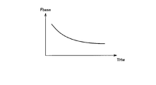
- FIG. 4 is a diagram showing a correspondence relationship between the engine water temperature THw and the basic fuel injection amount Fbase.
- the basic fuel injection amount Fbase increases as the engine coolant temperature THw decreases. This is to improve the startability of the engine 100 even when the engine coolant temperature THw is low. That is, when the engine coolant temperature THw is low, the engine friction torque is large, so that a larger amount of fuel injection is required. Further, when the engine water temperature THw is low, the temperature of the fuel in the delivery pipe 105 (hereinafter also simply referred to as “fuel temperature THf”) is predicted to be low.
- the basic fuel injection amount Fbase is increased as the engine coolant temperature THw is lower.
- the injection amount determination unit 825 determines the fuel injection amount F at the time of starting the engine and causes the injector 104 to inject the determined fuel injection amount F. At this time, the injection amount determination unit 825 changes the fuel injection amount F according to the execution history of the pre-air conditioning. This is the most characteristic point of the present invention.
- the injection amount determination unit 825 sets the basic fuel injection amount Fbase as the fuel injection amount F.
- the electric fan 400 is maintained in a stopped state before the engine is started, and therefore it is estimated that the engine water temperature THw and the fuel temperature THf are substantially the same temperature. Therefore, the basic fuel injection amount Fbase obtained from the engine coolant temperature THw includes a fuel increase amount for eliminating the influence of the deterioration of atomization due to the low fuel temperature THf. Therefore, when there is no pre-air conditioning execution history, the injection amount determination unit 825 uses the basic fuel injection amount Fbase obtained from the engine water temperature THw as the fuel injection amount F as it is.
- the injection amount determination unit 825 increases the fuel injection amount F based on a value obtained by increasing the basic fuel injection amount Fbase using the correction coefficient K (hereinafter also referred to as “corrected fuel injection amount”).
- corrected fuel injection amount a value obtained by increasing the basic fuel injection amount Fbase using the correction coefficient K (hereinafter also referred to as “corrected fuel injection amount”).
- the pre-air conditioning is executed and the electric fan 400 is operated, the internal temperature of the engine compartment 10 is lowered as described above. Due to this influence, the temperature of the delivery pipe 105 is lowered, and the fuel temperature THf is also lowered.
- the engine cooling water is relatively large, and the engine water temperature THw hardly changes even when the electric fan 400 is operated. That is, when electric fan 400 is operated, a difference occurs between fuel temperature THf and engine water temperature THw.
- the injection amount determination unit 825 sets the corrected fuel injection amount obtained by correcting the basic fuel injection amount Fbase using the correction coefficient K as the fuel injection amount F when there is an execution history of pre-air conditioning.
- the judgment of the pre-air conditioning execution history may be made based on whether or not the pre-air conditioning is actually executed, or the pre-air conditioning execution conditions may be established or the vehicle state change state that occurs when the pre-air conditioning is executed. You may perform based on the parameter relevant to execution of an air conditioning.
- the correction coefficient calculation unit 822 estimates the fuel temperature THf using the outside air temperature THout and the electric fan operation time T during the pre-air conditioning execution period as parameters.
- the electric fan operating time T may be the cumulative operating time of the electric fan 400, or may be an operating time that takes into account the operating mode of the electric fan 400 (for example, operating power, intermittent stop time, etc.).
- the correction coefficient calculation unit 822 sets the fuel temperature THf to a lower value as the outside air temperature THout is lower and the electric fan operation time T is longer (that is, the correction coefficient K described later has a larger value). To estimate).
- the correction coefficient calculation unit 822 calculates the correction coefficient K using the estimated fuel temperature THf as a parameter.
- FIG. 5 is a diagram showing the correspondence between the fuel temperature THf and the correction coefficient K.
- the correction coefficient K is set to a value larger than 1.0 as the fuel temperature THf is lower.
- the corrected fuel injection amount is increased by setting the correction coefficient K to a larger value as the estimated fuel temperature THf is lower than the engine water temperature THw, thereby responding to the difference between the fuel temperature THf and the engine water temperature THw.
- An appropriate fuel injection amount F can be determined. Therefore, even when fuel atomization is deteriorated due to a decrease in fuel temperature THf, startability of engine 100 can be ensured.
- ECU 800 does not correct the fuel injection amount using correction coefficient K when starting engine 100 while the vehicle is traveling.
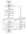
- FIG. 6 is a flowchart showing a processing procedure of the ECU 800 for realizing the above-described function.
- the flowchart shown in FIG. 6 is repeatedly executed at a predetermined cycle while the vehicle system is stopped (in a READY-OFF state).
- step (hereinafter, step is abbreviated as “S”) 10 ECU 800 determines whether or not pre-air conditioning is being executed.
- ECU 800 moves the process to S16 and determines whether or not it has been switched to the READY-ON state. When switched to the READY-ON state (YES in S16), ECU 800 determines that there is no pre-air-conditioning execution history, and calculates basic fuel injection amount Fbase from engine coolant temperature THw in S17 ( Further, in S18, the basic fuel injection amount Fbase is determined to be the fuel injection amount F as it is, and the fuel injection amount F is injected from the injector 104.
- ECU 800 estimates fuel temperature THf from outside temperature THout and electric fan operating time T as described above in S11. Then, ECU 800 calculates correction coefficient K from fuel temperature THf in S12 (see FIG. 5).
- ECU 800 determines in S13 whether or not it has been switched to the READY-ON state.
- ECU 800 determines that there is an execution history of pre-air conditioning, and ECU 800 calculates basic fuel injection amount Fbase from engine water temperature THw in S14 (FIG. 4).
- step S15 the product of the basic fuel injection amount Fbase and the correction coefficient K (corrected fuel injection amount) is determined as the fuel injection amount F, and the fuel injection amount F is injected from the injector 104.
- ECU 800 does not need to start engine 100, and ECU 800 ends the process without determining fuel injection amount F.
- the control device performs the pre-air conditioning execution history (the operation history of the electric fan) when starting the engine in a vehicle capable of executing the pre-air conditioning that air-conditions the vehicle interior before starting the vehicle system.
- the fuel injection amount is changed according to Therefore, even if a difference between the fuel temperature THf and the engine water temperature THw occurs due to the execution of pre-air conditioning (operation of the electric fan), the fuel injection amount F is appropriately adjusted according to the difference, and the engine 100 Can be secured.
- the case where the fuel injection amount, which is one of the targets for engine start control, is changed in accordance with the execution history of the pre-air conditioning has been described.
- the ignition timing, the opening / closing timing of the intake valve or the exhaust valve, the lift amount, the fuel pressure, etc. may be changed according to the execution history of the pre-air conditioning.
Landscapes
- Engineering & Computer Science (AREA)
- Mechanical Engineering (AREA)
- Chemical & Material Sciences (AREA)
- Combustion & Propulsion (AREA)
- General Engineering & Computer Science (AREA)
- Physics & Mathematics (AREA)
- Thermal Sciences (AREA)
- Control Of Vehicle Engines Or Engines For Specific Uses (AREA)
- Electrical Control Of Air Or Fuel Supplied To Internal-Combustion Engine (AREA)
Abstract
ECU(800)は、プレ空調制御部(810)と、エンジン始動制御部(820)とを含む。プレ空調制御部(810)は、プレ空調要求信号を受信すると、空調ユニットおよび電動ファンを作動させてプレ空調を行なう。エンジン始動制御部(820)は、エンジンを始動させる際、プレ空調の実行履歴がない場合は基本燃料噴射量Fbaseをインジェクタから噴射させる一方、プレ空調の実行履歴がある場合は基本燃料噴射量Fbaseを補正係数Kを用いて増量補正した補正燃料噴射量をインジェクタから噴射させる。
Description
この発明は、車両システム起動前に車室内を予め空調するプレ空調を実行可能な車両の制御に関する。
特開2006-298326号公報(特許文献1)には、ユーザの遠隔操作に応じて車両システム起動前に車室内を予め空調するプレ空調を実行可能な車両が開示されている。
ところで、プレ空調の実行中は、エンジンコンパートメント内に配置された空調用コンデンサを冷却するための電動ファンが作動されることがある。この電動ファンの作動によって、エンジンコンパートメント内の温度変化は自然放置時(電動ファンの非作動時)とは異なる態様となる。そのため、ユーザが乗車してエンジンを始動させる際、プレ空調の実行履歴がある場合とそうでない場合とで同じエンジン始動制御を行なうと、エンジンの始動性が悪化するおそれがある。
本発明は、上述の課題を解決するためになされたものであって、その目的は、車両システム起動前に車室内を予め空調するプレ空調を実行可能な車両において、エンジンの始動性を担保することである。
この発明に係る制御装置は、車両システム起動前に車室内を空調するプレ空調を実行可能な車両を制御する。車両は、エンジンと、エンジンを収容する収容室の内部に配置される空調用のコンデンサおよびコンデンサを冷却するための電動ファンとを備える。制御装置は、プレ空調の実行中に電動ファンを作動させるファン作動部と、エンジンを始動させる始動制御を実行する始動制御部とを備える。始動制御部は、エンジンを始動させる際、プレ空調の実行履歴に応じて始動制御の態様を変更する。
好ましくは、エンジンは、電動ファンの作動によって冷却される位置に配置される燃料供給配管と、燃料供給配管から供給される燃料をエンジンに噴射するための噴射弁とを備える。始動制御部は、エンジンを始動させる際、プレ空調の実行履歴に応じて噴射弁から噴射させる燃料量を変更する。
好ましくは、始動制御部は、エンジンを始動させる際、プレ空調の実行履歴がある場合、プレ空調の実行履歴がない場合に比べて、噴射弁から噴射させる燃料量を増加させる。
好ましくは、始動制御部は、エンジンを始動させる際、エンジン水温に基づいて基本燃料量を算出し、プレ空調の実行履歴がない場合は基本燃料量を噴射弁から噴射させ、プレ空調の実行履歴がある場合は基本燃料量よりも多い補正燃料量を噴射弁から噴射させる。
好ましくは、始動制御部は、プレ空調の実行期間中における電動ファンの作動時間に基づいて補正燃料量を変更する。
好ましくは、始動制御部は、プレ空調の実行期間中における電動ファンの作動時間が長いほど補正燃料量を増加させる。
好ましくは、始動制御部は、プレ空調の実行期間中における電動ファンの作動時間および外気温に基づいて燃料供給配管内の燃料温度を推定し、推定された燃料温度が低いほど補正燃料量を増加させる。
好ましくは、始動制御部は、電動ファンの作動時間が長いほどおよび外気温が低いほど燃料温度を低い値に推定する。
本発明によれば、車両システム起動前に車室内を予め空調するプレ空調を実行可能な車両において、エンジンの始動性を担保することができる。
以下、本発明の実施例について、図面を参照しながら詳細に説明する。なお、図中同一または相当部分には同一符号を付してその説明は繰り返さない。
図1は、本発明の実施例に従う車両1の全体ブロック図である。車両1は、エンジン100、ラジエータ200、コンデンサ300、電動ファン400、空調ユニット500、IGスイッチ600、受信装置700、ECU(Electronic Control Unit)800を備える。なお、本発明を適用可能な車両は、後述するプレ空調を実行可能なエンジン車両であれば図1に示す車両1に限定されるものではなく、たとえばエンジンに加えてモータを備える車両(いわゆるハイブリッド自動車やプラグインハイブリッド車両)であってもよい。また、エンジンの用途は、必ずしも車両走行用に限定されず、たとえば発電用であってもよい。
エンジン100は、車両1の前方側に設けられたエンジンコンパートメント10の内部に搭載される。エンジン100は、ECU800からの制御信号によって制御される。エンジン100の動力は、図示しない減速機等を介して車輪11に伝達される。これにより、車両1は、エンジン100の動力によって走行される。
エンジンコンパートメント10には、エンジン100の他に、ラジエータ200、コンデンサ300、電動ファン400、空調ユニット500が搭載される。
ラジエータ200は、配管210,220を経由してエンジン100の内部に設けられたウォータジャケット(図示せず)に連通される。ラジエータ200は、エンジン冷却水の熱を大気に放出するための放熱器である。図示しない電動ウォータポンプが駆動されることによって、エンジン冷却水がラジエータ200およびエンジン100の間を循環する(矢印A参照)。より具体的には、エンジン100の熱を吸収したエンジン冷却水は、ラジエータ200に送られてラジエータ200で放熱冷却され、その後再びエンジン100に戻される。これにより、エンジン100が冷却される。
コンデンサ300は、ラジエータ200に隣接して設けられ、配管310,320を経由して空調ユニット500に連通される。コンデンサ300は、空調用の冷媒ガスの熱を大気に放出させて凝縮するための凝縮器である。
空調ユニット500は、コンデンサ300の他に冷凍サイクルを実現するために必要な部品(コンプレッサ、膨張バルブ、エバポレータなど)を含んで構成される。空調ユニット500が作動することによって、空調用の冷媒がコンデンサ300および空調ユニットの間を循環する(矢印B参照)。より具体的には、空調ユニット500で加圧高温になった冷媒ガスがコンデンサ300に送られて凝縮(液化)され、その後再び空調ユニット500に戻される。このような冷凍サイクルにより、車室内の空調(冷房)が行なわれる。
電動ファン400は、エンジンコンパートメント10の内部における、ラジエータ200およびコンデンサ300の近傍に設けられる。電動ファン400は、ECU800からの制御信号によって制御される。電動ファン400が作動することによって、外気がラジエータ200およびコンデンサ300を通ってエンジンコンパートメント10の内部に取り込まれる(矢印C参照)。これにより、外気が冷却風として作用しラジエータ200およびコンデンサ300が冷却されるとともに、エンジンコンパートメント10の内部が掃気されエンジンコンパートメント10の内部温度が低下される。なお、電動ファン400をコンデンサ300用とラジエータ200用とで別々に設けるようにしてもよい。
IGスイッチ600は、車両システムの始動要求および停止要求をユーザが入力するためのスイッチである。「車両システム」とは、車両1の走行制御に必要な電気機器である。車両システムが停止状態(Ready-OFF状態)であるときにユーザがIGスイッチ600を操作すると、車両システムは起動状態(Ready-ON状態)に切り替えられ、エンジン100が始動される。
受信装置700は、リモートコントロール装置(以下、単に「リモコン」ともいう)20から送信されるプレ空調要求信号を受信するための装置である。ここで、「プレ空調」とは、ユーザ要求に応じて空調ユニット500および電動ファン400を作動させて車両システム起動前に予め車室内の空調を行なう制御のことである。車両システム起動前とは、Ready-ON状態となる前である。すなわち、走行制御に直接的には関係のないプレ空調は、車両システムによって実行されるものではなく、Ready-ON状態となる前に実行される。ユーザがリモコン20を遠隔操作すると、リモコン20からプレ空調要求信号が送信される。受信装置700は、このリモコン20からプレ空調要求信号を受信すると、プレ空調要求信号をECU800に送信する。
ECU800は、図示しないCPU(Central Processing Unit)およびメモリを内蔵し、当該メモリに記憶された情報や各センサからの情報に基づいて、所定の演算処理を実行するように構成される。
ECU800は、受信装置700からプレ空調要求信号を受信すると、空調ユニット500および電動ファン400を作動させてプレ空調を行なう。
図2は、エンジン100の構成を詳細に示す図である。なお、図2には1つの気筒が例示されているが、実際にはエンジン100には複数の気筒が設けられる。
エンジン100においては、エアクリーナ(図示せず)から吸入される空気が、吸気管110を通って、エンジン100の燃焼室102に導入される。スロットルバルブ114の作動量(スロットル開度)により、燃焼室102に導入される空気量が調整される。スロットル開度は、ECU800からの信号に基づいて作動するスロットルモータ112により制御される。
インジェクタ104は、ECU800からの制御信号によって開弁して、デリバリパイプ105内の燃料を燃焼室102へ向けて噴射する。なお、インジェクタ104から燃焼室102へ燃料を直接噴射するようにしてもよい。
吸気管110から導入された空気と、インジェクタ104から噴射された燃料との混合気が、ECU800からの制御信号により制御されるイグニッションコイル106を用いて着火されて燃焼する。混合気が燃焼した後の排気は、排気管120を通って大気に排出される。
ECU800には、外気温センサ107、水温センサ108、エアフロメータ116、吸気温センサ118からの信号が入力されている。外気温センサ107は、外気温(車両1の外部の空気の温度)THoutを検出する。水温センサ108は、エンジン水温(エンジン冷却水の温度)THwを検出する。エアフロメータ116は、吸入空気量(エンジン100に吸入される単位時間あたりの空気量)Gaを検出する。吸気温センサ118は、吸気温度(エンジン100に吸入される空気の温度)THaを検出する。これらの各センサは、検出結果を表わす信号をECU800に送信する。
ECU800は、各センサから送られてきた信号などに基づいてスロットルモータ112、イグニッションコイル106、インジェクタ104を制御することによって、スロットル開度、点火時期、燃料噴射量を制御する。
図3は、プレ空調制御およびエンジン始動制御を実行する際のECU800の機能ブロック図である。図3に示した各機能ブロックは、ハードウェアによって実現してもよいし、ソフトウェアによって実現してもよい。
ECU800は、プレ空調制御部810と、エンジン始動制御部820とを含む。
プレ空調制御部810は、上述したように、受信装置700からプレ空調要求信号を受信すると、空調ユニット500を作動させてプレ空調を行なう。この際、プレ空調制御部810は、電動ファン400を作動させてコンデンサ300を冷却する。なお、電動ファン400は、必ずしも常時作動させる必要はなく間欠的に作動させてもよい。
プレ空調制御部810は、上述したように、受信装置700からプレ空調要求信号を受信すると、空調ユニット500を作動させてプレ空調を行なう。この際、プレ空調制御部810は、電動ファン400を作動させてコンデンサ300を冷却する。なお、電動ファン400は、必ずしも常時作動させる必要はなく間欠的に作動させてもよい。
エンジン始動制御部820は、ユーザの始動要求(IGスイッチ600の操作)に応じてエンジン始動制御を実行する。ここで、「エンジン始動制御」とは、エンジン始動時のスロットル開度、点火時期、燃料噴射量などの制御をいう。以下では、エンジン始動制御の一例として、エンジン始動時の燃料噴射制御について説明する。
エンジン始動制御部820は、第1判定部821、補正係数算出部822、第2判定部823、基本噴射量算出部824、噴射量決定部825を含む。
第1判定部821は、プレ空調の実行中であるか否かを判定する。なお、プレ空調はユーザの遠隔操作によって実行されるため、プレ空調の実行中であるか否かの判定は、READY-OFF状態(エンジン停止状態)で行なわれるのが通常である。
補正係数算出部822は、プレ空調の実行中である場合、補正係数Kを算出する。ここで、補正係数Kとは、後述する基本燃料噴射量Fbaseを補正するための係数である。補正係数Kの算出手法については後に詳述する。
第2判定部823は、IG信号(IGスイッチ600からの信号)に基づいて、READY-OFF状態からREADY-ON状態に切り替えられたか否か(ユーザがIGスイッチ600に対して始動操作を行なったか否か)を判定する。
基本噴射量算出部824は、READY-ON状態に切り替えられた場合、エンジン水温THw(水温センサ108の検出値)に基づいて基本燃料噴射量Fbaseを算出する。
図4は、エンジン水温THwと基本燃料噴射量Fbaseとの対応関係を示す図である。図4に示されるように、エンジン水温THwが低い領域においては、エンジン水温THwが低いほど基本燃料噴射量Fbaseは増量される。これは、エンジン水温THwが低い場合であってもエンジン100の始動性を良好にするためである。すなわち、エンジン水温THwが低いと、エンジンフリクショントルクが大きいため、より多くの燃料噴射量が必要になる。また、エンジン水温THwが低いと、デリバリパイプ105内の燃料の温度(以下、単に「燃料温度THf」ともいう)も低いと予測される。燃料温度THfが低いと、インジェクタ104から噴射される燃料の霧化が悪化し、エンジン100の始動性が悪化すると予測される。これらの問題を考慮し、エンジン水温THwが低いほど基本燃料噴射量Fbaseが増量される。
噴射量決定部825は、エンジン始動時の燃料噴射量Fを決定し、決定された燃料噴射量Fをインジェクタ104から噴射させる。この際、噴射量決定部825は、プレ空調の実行履歴に応じて燃料噴射量Fを変更する。この点が本発明の最も特徴的な点である。
プレ空調の実行履歴がない場合、噴射量決定部825は、基本燃料噴射量Fbaseを燃料噴射量Fとする。プレ空調の実行履歴がない場合、エンジン始動前に電動ファン400は停止状態に維持されているため、エンジン水温THwと燃料温度THfとはほぼ同じ温度であると推定される。したがって、エンジン水温THwから求めた基本燃料噴射量Fbaseには、燃料温度THfが低いことによる霧化悪化の影響を排除するための燃料増量分が含まれていることになる。そこで、噴射量決定部825は、プレ空調の実行履歴がない場合には、エンジン水温THwから求めた基本燃料噴射量Fbaseをそのまま燃料噴射量Fとする。
一方、プレ空調の実行履歴がある場合、噴射量決定部825は、基本燃料噴射量Fbaseを補正係数Kを用いて増量補正した値(以下「補正燃料噴射量」ともいう)を燃料噴射量Fとする。プレ空調が実行されて電動ファン400が作動されると、上述したようにエンジンコンパートメント10の内部温度が低下される。この影響でデリバリパイプ105の温度が低下し、燃料温度THfも低下する。一方、エンジン冷却水は比較的多量でありエンジン水温THwは電動ファン400が作動してもほとんど変化しない。つまり、電動ファン400が作動することによって、燃料温度THfとエンジン水温THwとの間に差が生じる。しかしながら、エンジン水温THwから求めた基本燃料噴射量Fbaseには、その差(燃料温度THfの低下量)に対応するだけの燃料増量分は含まれていないことになる。そこで、噴射量決定部825は、プレ空調の実行履歴がある場合には、基本燃料噴射量Fbaseを補正係数Kを用いて補正した補正燃料噴射量を燃料噴射量Fとする。
なお、プレ空調の実行履歴の判断は、プレ空調の実際の実行有無に基づいて行なってもよいし、プレ空調の実行条件の成立状況やプレ空調の実行時に生じる車両状態の変化状況など、プレ空調の実行に関係するパラメータに基づいて行なってもよい。
ここで、補正係数算出部822による補正係数Kの算出手法について詳しく説明する。補正係数算出部822は、プレ空調の実行期間中における外気温THoutおよび電動ファン作動時間Tをパラメータとして燃料温度THfを推定する。ここで、電動ファン作動時間Tは、電動ファン400の累積作動時間であってもよいし、電動ファン400の作動態様(たとえば作動パワーや間欠停止時間など)を加味した作動時間であってもよい。たとえば、補正係数算出部822は、外気温THoutが低いほど、および、電動ファン作動時間Tが長いほど、燃料温度THfが低い値になるように(すなわち後述する補正係数Kが大きい値になるように)推定するようにすればよい。
そして、補正係数算出部822は、推定した燃料温度THfをパラメータとして補正係数Kを算出する。
図5は、燃料温度THfと補正係数Kとの対応関係を示す図である。図5に示すように、燃料温度THfがエンジン水温THwと一致する場合、補正係数算出部822は、補正係数K=1.0に設定する。そして、燃料温度THf<エンジン水温THwの場合は、燃料温度THfが低いほど補正係数Kを1.0よりも大きい値に設定する。このように、推定された燃料温度THfがエンジン水温THwよりも低いほど補正係数Kを大きい値に設定して補正燃料噴射量を増加させることによって、燃料温度THfとエンジン水温THwとの差に応じた適切な燃料噴射量Fを決定することができる。そのため、燃料温度THfの低下によって燃料の霧化が悪化している場合であっても、エンジン100の始動性を担保することができる。
なお、車両走行中は、比較的多量の走行風がエンジンコンパートメント10の内部に取り込まれるため、電動ファン400の作動の有無によって燃料温度THfとエンジン水温THwとの差はほとんど生じない。そのため、ECU800は、車両走行中にエンジン100を始動させる際には、補正係数Kを用いた燃料噴射量の補正は行なわない。
図6は、上述の機能を実現するためのECU800の処理手順を示すフローチャートである。図6に示すフローチャートは、車両システムの停止中(READY-OFF状態である場合)に予め定められた周期で繰り返し実行される。
ステップ(以下、ステップを「S」と略す)10にて、ECU800は、プレ空調の実行中であるか否かを判定する。
プレ空調の実行中でない場合(S10にてNO)、ECU800は、処理をS16に移し、READY-ON状態に切り替えられたか否かを判定する。そして、READY-ON状態に切り替えられた場合(S16にてYES)、ECU800は、プレ空調の実行履歴がないものと判定して、S17にてエンジン水温THwから基本燃料噴射量Fbaseを算出し(図4参照)、さらにS18にて基本燃料噴射量Fbaseをそのまま燃料噴射量Fに決定し、燃料噴射量Fをインジェクタ104から噴射させる。
一方、プレ空調の実行中である場合(S10にてYES)、ECU800は、S11にて上述したように外気温THoutおよび電動ファン作動時間Tから燃料温度THfを推定する。そして、ECU800は、S12にて燃料温度THfから補正係数Kを算出する(図5参照)。
その後、ECU800は、S13にて、READY-ON状態に切り替えられたか否かを判定する。READY-ON状態に切り替えられた場合(S13にてYES)、プレ空調の実行履歴があるものと判定して、ECU800は、S14にてエンジン水温THwから基本燃料噴射量Fbaseを算出し(図4参照)、さらにS15にて基本燃料噴射量Fbaseと補正係数Kとの積(補正燃料噴射量)を燃料噴射量Fに決定し、燃料噴射量Fをインジェクタ104から噴射させる。
なお、READY-OFF状態が維持されている場合(S13にてNO、S16にてNO)、エンジン100を始動させる必要がないため、ECU800は、燃料噴射量Fを決定することなく、処理を終了させる。
以上のように、本実施例に従う制御装置は、車両システム起動前に車室内を空調するプレ空調を実行可能な車両において、エンジンを始動させる際、プレ空調の実行履歴(電動ファンの作動履歴)に応じて燃料噴射量を変更する。そのため、プレ空調の実行(電動ファンの作動)によって燃料温度THfとエンジン水温THwとの差が生じた場合であっても、その差に応じて燃料噴射量Fを適切に調整して、エンジン100の始動性を担保することができる。
なお、本実施例では、エンジン始動制御の対象の1つである燃料噴射量をプレ空調の実行履歴に応じて変更する場合を説明したが、たとえば、エンジン始動制御の他の対象(スロットル開度、点火時期、吸気バルブあるいは排気バルブの開閉タイミングやリフト量、燃料圧など)をプレ空調の実行履歴に応じて変更するようにしてもよい。
今回開示された実施例はすべての点で例示であって制限的なものではないと考えられるべきである。本発明の範囲は上記した説明ではなくて請求の範囲によって示され、請求の範囲と均等の意味および範囲内でのすべての変更が含まれることが意図される。
1 車両、10 エンジンコンパートメント、11 車輪、20 リモコン、100 エンジン、102 燃焼室、104 インジェクタ、105 デリバリパイプ、106 イグニッションコイル、107 外気温センサ、108 水温センサ、110 吸気管、112 スロットルモータ、114 スロットルバルブ、116 エアフロメータ、118 吸気温センサ、120 排気管、200 ラジエータ、210,220,310,320 配管、300 コンデンサ、400 電動ファン、500 空調ユニット、600 IGスイッチ、700 受信装置、800 ECU、810 プレ空調制御部、820 エンジン始動制御部、821 第1判定部、822 補正係数算出部、823 第2判定部、824 基本噴射量算出部、825 噴射量決定部。
Claims (8)
- 車両システム起動前に車室内を空調するプレ空調を実行可能な車両の制御装置であって、
前記車両は、エンジン(100)と、前記エンジンを収容する収容室(10)の内部に配置される空調用のコンデンサ(300)および前記コンデンサを冷却するための電動ファン(400)とを備え、
前記制御装置は、
前記プレ空調の実行中に前記電動ファンを作動させるファン作動部(810)と、
前記エンジンを始動させる始動制御を実行する始動制御部(820)とを備え、
前記始動制御部は、前記エンジンを始動させる際、前記プレ空調の実行履歴に応じて前記始動制御の態様を変更する、車両の制御装置。 - 前記エンジンは、前記電動ファンの作動によって冷却される位置に配置される燃料供給配管(105)と、前記燃料供給配管から供給される燃料を前記エンジンに噴射するための噴射弁(104)とを備え、
前記始動制御部は、前記エンジンを始動させる際、前記プレ空調の実行履歴に応じて前記噴射弁から噴射させる燃料量を変更する、請求項1に記載の車両の制御装置。 - 前記始動制御部は、前記エンジンを始動させる際、前記プレ空調の実行履歴がある場合、前記プレ空調の実行履歴がない場合に比べて、前記噴射弁から噴射させる燃料量を増加させる、請求項2に記載の車両の制御装置。
- 前記始動制御部は、前記エンジンを始動させる際、エンジン水温に基づいて基本燃料量を算出し、前記プレ空調の実行履歴がない場合は前記基本燃料量を前記噴射弁から噴射させ、前記プレ空調の実行履歴がある場合は前記基本燃料量よりも多い補正燃料量を前記噴射弁から噴射させる、請求項2に記載の車両の制御装置。
- 前記始動制御部は、前記プレ空調の実行期間中における前記電動ファンの作動時間に基づいて前記補正燃料量を変更する、請求項4に記載の車両の制御装置。
- 前記始動制御部は、前記プレ空調の実行期間中における前記電動ファンの作動時間が長いほど前記補正燃料量を増加させる、請求項5に記載の車両の制御装置。
- 前記始動制御部は、前記プレ空調の実行期間中における前記電動ファンの作動時間および外気温に基づいて前記燃料供給配管内の燃料温度を推定し、推定された前記燃料温度が低いほど前記補正燃料量を増加させる、請求項5に記載の車両の制御装置。
- 前記始動制御部は、前記電動ファンの作動時間が長いほどおよび前記外気温が低いほど前記燃料温度を低い値に推定する、請求項7に記載の車両の制御装置。
Priority Applications (1)
| Application Number | Priority Date | Filing Date | Title |
|---|---|---|---|
| PCT/JP2011/054279 WO2012114505A1 (ja) | 2011-02-25 | 2011-02-25 | 車両の制御装置 |
Applications Claiming Priority (1)
| Application Number | Priority Date | Filing Date | Title |
|---|---|---|---|
| PCT/JP2011/054279 WO2012114505A1 (ja) | 2011-02-25 | 2011-02-25 | 車両の制御装置 |
Publications (1)
| Publication Number | Publication Date |
|---|---|
| WO2012114505A1 true WO2012114505A1 (ja) | 2012-08-30 |
Family
ID=46720321
Family Applications (1)
| Application Number | Title | Priority Date | Filing Date |
|---|---|---|---|
| PCT/JP2011/054279 Ceased WO2012114505A1 (ja) | 2011-02-25 | 2011-02-25 | 車両の制御装置 |
Country Status (1)
| Country | Link |
|---|---|
| WO (1) | WO2012114505A1 (ja) |
Citations (4)
| Publication number | Priority date | Publication date | Assignee | Title |
|---|---|---|---|---|
| JP2001012291A (ja) * | 1999-06-28 | 2001-01-16 | Denso Corp | 内燃機関用燃料噴射制御装置 |
| JP2001152920A (ja) * | 1999-11-30 | 2001-06-05 | Unisia Jecs Corp | エンジンの燃料圧力制御装置 |
| JP2005030252A (ja) * | 2003-07-09 | 2005-02-03 | Nissan Motor Co Ltd | 内燃機関の始動装置 |
| JP2006298326A (ja) * | 2005-04-25 | 2006-11-02 | Toyota Motor Corp | 車両用空調装置 |
-
2011
- 2011-02-25 WO PCT/JP2011/054279 patent/WO2012114505A1/ja not_active Ceased
Patent Citations (4)
| Publication number | Priority date | Publication date | Assignee | Title |
|---|---|---|---|---|
| JP2001012291A (ja) * | 1999-06-28 | 2001-01-16 | Denso Corp | 内燃機関用燃料噴射制御装置 |
| JP2001152920A (ja) * | 1999-11-30 | 2001-06-05 | Unisia Jecs Corp | エンジンの燃料圧力制御装置 |
| JP2005030252A (ja) * | 2003-07-09 | 2005-02-03 | Nissan Motor Co Ltd | 内燃機関の始動装置 |
| JP2006298326A (ja) * | 2005-04-25 | 2006-11-02 | Toyota Motor Corp | 車両用空調装置 |
Similar Documents
| Publication | Publication Date | Title |
|---|---|---|
| JP4857821B2 (ja) | 車両の制御方法及び制御装置 | |
| US8607552B2 (en) | Emission control system with heat recovery device | |
| US9163603B2 (en) | Control system for internal combustion engine | |
| CN106347070A (zh) | 用于压缩机离合器控制的系统和方法 | |
| JP5352617B2 (ja) | 内燃機関の停止制御装置 | |
| JP3452030B2 (ja) | 車両用空調制御装置 | |
| US10060333B2 (en) | Systems and methods for engine coolant system diagnostics | |
| US9194356B2 (en) | Stop control system for internal combustion engine | |
| JP5035392B2 (ja) | 内燃機関の制御装置 | |
| CN105074197B (zh) | 用于车辆的控制装置及控制方法 | |
| JP2012215152A (ja) | 内燃機関の排ガス浄化装置 | |
| WO2012114505A1 (ja) | 車両の制御装置 | |
| JP5556791B2 (ja) | 内燃機関の暖機制御装置 | |
| JP4576748B2 (ja) | 内燃機関の出力制御装置 | |
| JP6531716B2 (ja) | 車両用空調装置のトルク推定装置 | |
| JP2011220208A (ja) | 内燃機関の制御装置 | |
| JP2006327394A (ja) | 車載空調装置の制御装置 | |
| US9658200B2 (en) | Control method of sensor disposed in exhaust system | |
| JP2005351120A (ja) | 内燃機関の制御装置 | |
| JP6091300B2 (ja) | 車両の制御装置 | |
| JP2005299425A (ja) | 冷却水温度制御装置 | |
| JP6129504B2 (ja) | 制御装置 | |
| JP2012082697A (ja) | エンジン回転停止制御装置 | |
| JP2016031062A (ja) | 内燃機関によってエアコンディショナを駆動する車両 | |
| JP2016124454A (ja) | 空調制御装置 |
Legal Events
| Date | Code | Title | Description |
|---|---|---|---|
| DPE2 | Request for preliminary examination filed before expiration of 19th month from priority date (pct application filed from 20040101) | ||
| 121 | Ep: the epo has been informed by wipo that ep was designated in this application |
Ref document number: 11859643 Country of ref document: EP Kind code of ref document: A1 |
|
| NENP | Non-entry into the national phase |
Ref country code: DE |
|
| 122 | Ep: pct application non-entry in european phase |
Ref document number: 11859643 Country of ref document: EP Kind code of ref document: A1 |
|
| NENP | Non-entry into the national phase |
Ref country code: JP |