WO2012114371A1 - メッセージ送信装置及びメッセージ送信方法 - Google Patents
メッセージ送信装置及びメッセージ送信方法 Download PDFInfo
- Publication number
- WO2012114371A1 WO2012114371A1 PCT/JP2011/000998 JP2011000998W WO2012114371A1 WO 2012114371 A1 WO2012114371 A1 WO 2012114371A1 JP 2011000998 W JP2011000998 W JP 2011000998W WO 2012114371 A1 WO2012114371 A1 WO 2012114371A1
- Authority
- WO
- WIPO (PCT)
- Prior art keywords
- message
- protocol
- network
- data
- transmitting
- Prior art date
Links
Images


Classifications
-
- H—ELECTRICITY
- H04—ELECTRIC COMMUNICATION TECHNIQUE
- H04L—TRANSMISSION OF DIGITAL INFORMATION, e.g. TELEGRAPHIC COMMUNICATION
- H04L69/00—Network arrangements, protocols or services independent of the application payload and not provided for in the other groups of this subclass
- H04L69/18—Multiprotocol handlers, e.g. single devices capable of handling multiple protocols
Definitions
- the present invention relates to an apparatus and a method for transmitting data to a message receiving apparatus.
- a technology called smart grid which introduces IT technology in the field of power control and promotes efficient use of power, is attracting attention.
- network communication technology is used to transmit and receive information between devices constituting the smart grid.
- the data center device may directly send a command to the device via this network.
- private information such as the amount of power used and the usage time of power equipment may be transmitted and received. For example, if information on the usage time of an air conditioner is leaked in summer, the user's staying time becomes clear, and it can be misused for crimes such as vacant nests. In order to transmit and receive these pieces of information, a stable communication operation is required.
- Patent Document 1 discloses a technique for monitoring a network state between devices and controlling the protocol in the same protocol according to the network state. Specifically, when a link abnormality such as congestion is detected by monitoring the network by SNMP, a network traffic control is performed by transmitting a signal such as congestion control.
- the present invention relates to a message transmission device that transmits data to a message reception device, based on the reception unit that receives data including information about the state of the message reception device with respect to the network, and the received information about the state of the network.
- a determination unit that determines a state of the message reception device with the network, a protocol selection unit that selects a protocol based on the determined network state, and a transmission unit that transmits data to the message reception device using the protocol It is characterized by.
- data can be transmitted between devices even in a situation where communication is unstable.
- FIG. 2 is a diagram illustrating an example of the configuration of a data center apparatus 100.
- FIG. 3 is a diagram illustrating an example of the configuration of a home server 101.
- FIG. 3 is an exemplary diagram of a configuration of a power device 103.
- FIG. 4 is a diagram illustrating an example of the configuration of a display terminal 104.
- FIG. 6 is a diagram showing an example of the configuration of a message transmission policy DB 207.
- FIG. 4 is a diagram illustrating an example of the configuration of a use protocol determination policy DB 208.
- FIG. 4 is a diagram illustrating an example of the configuration of a network status DB 210.
- FIG. 1 The figure of an example of a structure of network status determination DB211.
- FIG. The flowchart which is an example of the flow of a process of the electric energy transmission program 507.
- FIG. 1 is a diagram showing an entire system for carrying out the present invention.
- the data center apparatus 100 is a computer for transmitting / receiving information to / from the home server 101, the adapter 102, the power device 103, the display terminal 104, and the like connected to the data center apparatus 100.
- the data center device 100 is connected to a plurality of houses (house 1000, house 1001) via a network 105.
- the home server 101 is a computer that exists between the data center apparatus 101, the power device 103, and the display apparatus 104 and transmits and receives data.
- the home server 101 is connected to the data center apparatus 100 via the network 105.
- the network 105 is a network that exchanges packets such as TCP and UDP, for example, like the Internet.
- the home server 101 is also connected to the adapter 102 via the network 106.
- the network 106 is a local network in a home, for example, and packets such as TCP and UDP are exchanged in a LAN environment.
- the adapter 102 is a computer that receives data from the power device 103 and the display terminal 104 and transmits data to the data center device 100 via the home server 101.
- the adapter 102 is connected to the power device 103 and the display terminal 104 through the communication path 107.
- the communication path 107 is, for example, an IP network, a PLC (power line communication) network, or a wireless communication network that communicates using TCP, which is a protocol with a high network load, or UDP, which is a protocol with a low network load.
- the IP network is a network that communicates using the Internet protocol
- TCP and UDP are names of protocols that perform communication in an upper layer of the Internet protocol.
- UDP only sends a packet from one device participating in the network to another device, whereas TCP checks the arrival of packets and the order of arrival at the protocol level. . Therefore, when the two protocols are compared, communication with a higher security level is guaranteed with TCP. Also, because TCP has more data than UDP, network congestion is likely to occur.
- the power device 103 is a device that consumes power.
- the power device 103 is a home device such as an air conditioner or a blind, for example. However, it is assumed here that the blind has a power unit that can be opened and closed by an instruction from the outside.
- the display terminal 104 is a terminal for displaying information acquired through the communication path 107.
- the display terminal 104 is a television, for example.
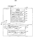
- FIG. 2 is a diagram showing the configuration of the data center apparatus 100.
- the data center apparatus 100 is a computer including a CPU 201, a storage device 202, a memory 203, and an interface 204 (hereinafter, the interface is referred to as IF in the figure) input / output device 205, which are connected via a communication path 206. ing.
- the storage device 202 includes data processed by the CPU 206. It is a storage device such as a hard disk device, and stores the following data processed by the data center device 100.
- DB means database.
- the message transmission policy DB 207 is a database that defines a correspondence between a network state and a message to be transmitted in that state.
- the used protocol determination policy DB 208 is a database that defines which protocol is used depending on the network state.
- the transmission message DB 209 is a database that stores the contents of messages to be transmitted according to the network status.
- the network status DB 210 is a database for storing data such as the network execution transfer rate and the packet loss rate.
- the network status determination DB 211 is a database that defines conditions relating to the network status and the rank of the network status under the conditions.
- the memory 203 is a storage medium that includes a program processed by the CPU 201, and includes the following programs.
- Network property collection program 212 collects information such as packet loss and transfer rate from the network to determine the network status, and the message transmission program 213 selects an appropriate protocol message according to the network status and transmits it. It is a program to do. There may be an implementation in which the program is temporarily recorded in the storage device 202 and read into the memory 203 and executed when the CPU 201 executes the program.
- the network property collection program 212 stores a reception unit 220 and a network determination unit 221.
- the receiving unit 220 acquires data received by the data center device 100.
- the network determination unit 221 determines the status of the network.
- the message transmission program 213 stores a message selection unit 222, a protocol selection unit 223, and a transmission unit 224.
- the message selection unit 222 selects a message transmitted by the data center device 100.
- the protocol selection unit 223 selects a protocol transmitted by the data center device 100.
- the transmission unit 224 transmits the message generated by the data center device 100.
- the interface 204 is a communication interface for performing external communication with the data center apparatus 100.
- the interface 204 is connected to the external network 105.
- the input / output device 205 is a device for inputting / outputting data to / from the data center device 100, and is, for example, a display, a keyboard, or a mouse.
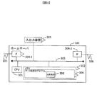
- FIG. 3 is a diagram showing the configuration of the home server 101.
- the home server 101 is a computer including a CPU 301, a memory 302, an input / output device 303, and an interface 304, which are connected via a communication path 305.
- the memory 302 is a storage medium that includes a program processed by the CPU 301, and includes a data transmission / reception program 306.
- the data transmission / reception program 306 stores a transmission / reception unit 320.
- the transmission / reception unit 320 acquires data received by the home server 101 and transmits a message generated by the home server 101.
- the input / output device 303 is a device for inputting / outputting data to / from the home server, such as a display, a keyboard, and a mouse.
- An interface 304 is a communication interface for performing external communication with the data center apparatus 100.
- the interfaces 304-1 and 304-2 are connected to different networks, and connect the two networks.
- the interface 304-1 is connected to the external network 105, and the interface 304-2 is connected to the home network 106.
- FIG. 4 is a diagram illustrating the configuration of the adapter 102.
- An adapter is a device that converts data media.
- the adapter 102 is a computer including a CPU 401, a memory 402, an input / output device 403, and an interface 404, which are connected via a communication path 405.
- the memory 402 is a storage medium that includes a program processed by the CPU 401, and includes a data transmission / reception program 406.
- the data transmission / reception program 406 stores a transmission / reception unit 420.
- the transmission / reception unit 420 acquires data received by the adapter 102 and transmits a message generated by the adapter 102.
- the input / output device 403 is a device for inputting / outputting data to / from the adapter, such as a display, a keyboard, and a mouse.
- the interface 404 is a communication interface for performing external communication with the data center apparatus 100.
- the interfaces 404-1 and 404-2 are connected to different networks and connect the two networks.
- the interface 404-1 is connected to the home network 106, and the interface 404-2 is connected to the communication path 107 with the electrical equipment.
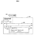
- FIG. 5 is a diagram showing the configuration of the power device 103.
- the power device 103 is a computer including a CPU 501, a memory 502, an interface 503, an input / output device 504, and a control device 505, which are connected via a communication path 506.
- the memory 502 is a storage medium that includes a program processed by the CPU 401, and includes the following programs.
- the power amount transmission program 507 is a program for transmitting the power consumption amount of the electric device.
- the operation control program 508 is a program that controls the operation of the power device 103.
- the power amount transmission program 507 stores a transmission unit 520.
- the transmission unit 520 transmits a message generated by the electric device 103.
- the operation control program 508 stores a receiving unit 521 and a control unit 522.
- the receiving unit 521 receives a control message.
- the control unit executes control of the power device 103 based on the received control message.
- the control message is a command transmitted to execute control of the power device 103, and the state of the power device 103 is changed by inputting this command.
- the power device 103 is an air conditioner
- the power supply of the air conditioner is turned on or off, or the set temperature is changed.
- An interface 503 is a communication interface for performing external communication with the data center apparatus 100.
- the interface 503 is connected to the communication path 107.
- the input / output device 504 is a device for inputting / outputting data to / from the adapter, such as a display or a remote controller.
- the control device 505 is a device for controlling a device such as a home appliance to which the power device 103 is connected. For example, assume that the home appliance is an air conditioner. When a switch ON control message is sent from the power device 103 to the control device 505, the air conditioner switch is turned ON.
- the measuring device 509 is a device that measures the amount of electricity used by the power device 103.
- FIG. 6 is a diagram showing the configuration of the display terminal 104.
- the display terminal 104 is a computer including a CPU 601, a memory 602, an interface 603, and an input / output device 604, which are connected via a communication path 605.
- the memory 602 is a storage medium that includes a program processed by the CPU 601 and includes the following programs.
- the data display program 606 is a program that displays received data.
- the data display program 606 stores a receiving unit 620 and a display unit 621.
- the receiving unit 620 receives data.
- the display unit 621 displays received data.
- An interface 603 is a communication interface for performing external communication with the display terminal 104.
- the interface 603 is connected to the communication path 107.
- the input / output device 604 is a device for inputting / outputting data to / from the display terminal, and is, for example, a display or a remote controller.
- FIG. 7 is a diagram showing the configuration of the message transmission policy DB 207.
- the message transmission policy DB 207 is a database that defines a correspondence between a network state and a message to be transmitted in that state.
- ID 701 is a unique identifier for identifying data.
- the message type 702 is a character string that describes the category of the message. For example, a message is related to “control information”.
- the transmission / reception type 703 is data indicating whether the message included in the message type is a transmission message or a reception message.
- the network state 704 is a matrix in which a flag indicating whether or not a message of a certain message type should be sent when the network state is of a certain type.
- the message type “control information” defines a policy such that it is transmitted when the network state is A, or is not transmitted when the network status is B or C (or an alternative message is transmitted). Which ID 701 is to be transmitted may be determined by a person.
- FIG. 8 is a diagram showing the configuration of the use protocol determination policy DB 208.
- the used protocol determination policy DB 208 is a database that defines which protocol is used depending on the network state.
- ID 801 is a unique identifier for identifying data.
- the network status 802 is an identifier when the network status is classified into categories.
- the used protocol 803 is a type of protocol used corresponding to the network state 802.
- the protocol used in addition to protocol types such as TCP and UDP, the protocol type in the application layer such as HTTP, the type of authentication / encryption protocol used at the time of communication, and the like are defined as necessary.
- selection of whether to use PKI authentication or ID and password authentication is specified according to the communication environment. In the following, the embodiment will be described using an example of selecting TCP and UDP on IP as an example of protocol selection.
- FIG. 9 is a diagram showing a configuration of the transmission message DB 209.
- the transmission message DB 209 is a database that stores the contents of messages to be transmitted according to the network status.
- ID 901 is a unique identifier for identifying data.
- the ID 901 corresponds to the ID 701 in the message transmission policy DB 207, and represents the same data when the identifier of the ID 901 and the identifier of the ID 701 are the same.
- the regular message 902 is a character string indicating the content of the message.
- the regular message is a message that has a significant influence on the device, such as controlling the device.
- the alternative message 903 is a character string of an alternative message to be transmitted when it is selected not to transmit the message 902.
- the substitute message is a message that has a slight influence on the device, such as sending a control request to the device.
- the reliability such as the ON / OFF control of the air conditioner switch such as using a protocol such as TCP is used. If this is not the case, use a protocol with a lighter network load than TCP, such as UDP.
- TCP Transmission Control Protocol
- UDP User Datagram Protocol
- the person who manages the air conditioner sees the message and can send a message.
- a protocol suitable for more complicated communications such as TCP is used, and sending and receiving messages that do not require much reliability.
- implementation is often performed in which communication is performed using a protocol with a lighter network load such as UDP and a light security corresponding to the protocol.
- FIG. 10 is a diagram showing the configuration of the network status DB 210.
- the network status DB 210 is a database for storing data such as the network execution transfer rate and the packet loss rate.
- the execution transfer rate is calculated from the number of packets transmitted / received per unit time by the data center device 100.
- the response time is calculated by the data center device 100 by measuring how long it takes a response (ACK response or the like) to the transmitted packet.
- ID 1001 is a unique identifier for identifying data.
- the communication destination IP address 1002 is an IP address for specifying a communication destination device that communicates with the data center apparatus 100.
- the network status 1003 is an identifier that categorizes the network status.
- the effective transfer rate 1004 is a transfer rate when the data center device 100 and the device having the communication destination IP address 1002 communicate with each other.
- the packet loss rate 1005 is a ratio of packets lost when performing the communication.
- the response time 1006 is an average response time when performing the communication.
- FIG. 11 is a diagram showing the configuration of the network status determination DB 211.
- the network status determination DB 211 is a matrix that defines conditions relating to the network status and the ranks of the network status under those conditions.
- ID 1101 is a unique identifier for identifying data.
- the network status 1102 is an identifier indicating the rank of the network status.
- the transfer speed 1103 is a condition regarding the transfer speed.
- the packet loss rate 1104 is a condition regarding the packet loss rate.
- Response time 1105 is a condition related to response time.
- the network state 1102 is defined as a rank corresponding to the condition. For example, if the item 1103 satisfies the network state A, the item 1104 satisfies the network state B, and the item 1105 satisfies the network state C, the network state C is determined as a whole.
- FIG. 12 is a flowchart showing the flow of processing of the network property collection program 212.
- the network property acquisition process 1201 is a process in which the receiving unit 220 acquires a property of communication between the data center apparatus 100 and a communication destination IP address.
- the properties here are the transfer rate, packet loss rate, and response time of communication between the data center apparatus 100 and the communication destination IP address.
- the network determination unit 221 inquires the conditions of the network status determination DB 211 from the data received, determines the network status 1102, and writes the result to the network status DB 210.
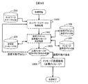
- FIG. 13 is a flowchart showing a processing flow of the message transmission program 213.
- the transmission unit 224 acquires the network state at the time when this process is executed from the network status DB 210.
- the message selection unit 222 and the protocol selection unit 223 refer to the transmission destination IP address 1002 and the network status 1003, and the protocol used when communicating with the device having the communication destination IP address 1002. Determine the message.
- the network determination unit determines a network congestion state.
- determining the network congestion state means, for example, determining whether the network state is free or congested. If it is determined that the network is free, a protocol with a high network load is selected.
- a protocol with a low network load is selected.
- communication reliability is ensured, so a regular message that is a message with a large amount of data is selected.
- a protocol with a low network load is selected, the reliability of communication is not ensured, so an alternative message that is a message with a small amount of data is selected.
- the message transmission policy DB 207 and the use protocol determination policy DB 208 are used as criteria for determination.
- the message is transmitted to the destination IP address.
- a control message is a message that directly accompanies a physical operation of an air conditioner or the like, and therefore a secure communication path with high security encryption and authentication is secured and transmitted over TCP, but the communication environment is poor.
- a control message is not a control message that directly controls, but a control recommendation message that includes only information that prompts control.
- FIG. 14 is a flowchart showing a processing flow of the data transmission / reception program 306.
- the data transmission / reception program 306 is a data reception process 1401, and the transmission / reception unit 320 outputs data received from one of the two interfaces 204 in the home server from the other interface by the data transmission process 1402. For example, the data received from the interface 204-1 is output from the interface 204-2.
- the media at the time of reception and the media at the time of transmission are different, the header information and the like are added so that the media is converted at the time of transmission.
- the media refers to the type of communication path such as Ethernet (registered trademark) connection, serial connection, or connection using a wireless protocol. That is, the data transmission / reception program 306 plays a role of relaying data. When the reception and transmission protocols are the same, the input data is simply output as it is.
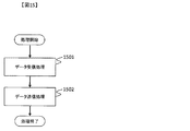
- FIG. 15 is a flowchart showing a processing flow of the data transmission / reception program 406.
- the data transmission / reception program 406 outputs the data received by the transmission / reception unit 420 from one of the two interfaces 204 in the home server in the data reception process 1501 from the other interface of the data transmission process 1502. At this time, if the protocol at the time of reception and the protocol at the time of transmission are different, the header information is added so as to comply with the protocol used at the time of transmission.
- the transmission / reception unit 421 has the same protocol at the time of reception and transmission, it simply transmits the input data.
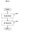
- FIG. 16 is a flowchart showing a processing flow of the electric energy transmission program 507.
- the power amount transmission program 507 calculates a power usage amount at the time when the measurement device 509 executes the program in the power amount measurement processing 1601 and transmits the power amount acquired by the processing 1601 in the power amount transmission processing 1602 to the transmission unit. 520 transmits to the data center apparatus 100.
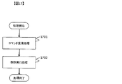
- FIG. 17 is a flowchart showing the flow of processing of the data reception program 508.
- the receiving unit 521 receives a control message input from the interface 503, analyzes the control message in a control message receiving process 1701, and transmits the control message to the control device 505 in a control execution process 1702. 522 controls the electric power device 103.
- the power device 103 is an air conditioner and a control message “switch ON” is input from the outside, this control message is interpreted by the device operation control program 507 and the switch of the air conditioner is turned “ON”.
- FIG. 18 is a flowchart showing the flow of processing of the data display program 606.
- the receiving unit 620 receives data input from the interface 603 by the data receiving process 1601.
- the display unit 621 displays the data on the input / output device 604 by the data display processing 1602.
- An example of a display destination input / output device is, for example, a television screen.
- the data center apparatus 100 and each device can be changed so as to periodically transmit and receive data. It is.
- the data in this case is set to a level that does not place a heavy load on the processing capacity of the network and each device.
- the meaning of the data content itself is not particularly limited here. As an example, data such as PING in a TCP / IP network can be considered. With this change, more accurate values can be calculated when calculating network properties.
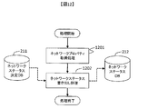
- FIG. 19 is a flowchart showing the processing flow of the message transmission program 213, which is the second embodiment of FIG. 1303 in FIG. 13 corresponds to 1903 and 1904 in FIG.
- step 1903 of FIG. 19 when it is determined that the information transmitted / received between the data center apparatus 100 and each device is the alternative message 903, the message 902 that should have been originally transmitted is temporarily stored in the memory of the transmission source. Saved in the storage device (202 or 203) (the structure of this saved data will be described later in FIG. 20), and when the network property becomes capable of sending the message 902 later, the saved messages are sent together.
- the unit 224 can also transmit.
- processes 1301 and 1302 in FIG. 19 are the same as the processes having the same numbers in FIG.
- the message transmission process 1904 is equivalent to the message transmission process 1303 in FIG. 13, but only regular messages are sent in FIG. 19.
- a message once transmitted is illustrated. Note that the data is deleted from the database described later.
- the alternative message is, for example, a control recommendation message. If the message is an alternative message in 1903, it may return to the network status acquisition process (1301) after transmitting the alternative message.
- FIG. 20 shows the configuration of the database used in the processing of FIG.
- This database stores message data to be transmitted, and once transmitted, the data is deleted. This change makes it possible to transmit a message to be sent without loss even if the network condition temporarily deteriorates.
- an embodiment in which the user sleeps for a certain period of time without sending a message and returns to the network status 1301 is possible. This change makes it possible to send the message 902 after the network state is recovered without performing an operation to load the network when the network state is bad.
Abstract
天候の変化等によってネットワークの環境が大きく変化した場合、通信が不安定になる。通信速度が落ちるため、同一プロトコル内での通信は不安定になる。 本発明は、メッセージ受信装置にデータを送信するメッセージ送信装置において、メッセージ受信装置のネットワークとの状態に関する情報を含んだデータを受信する受信部と、受信したネットワークの状態に関する情報に基づいて、メッセージ受信装置のネットワークとの状態を判定する判定部と、判定されたネットワークの状態に基づいてプロトコルを選択するプロトコル選択部と、プロトコルでデータをメッセージ受信装置に送信する送信部とを備えることを特徴とする。
Description
本発明は、データをメッセージ受信装置に送信する装置及び方法に関する。
電力制御の分野にIT技術を導入し、電力の効率的な利用を促進する、スマートグリッドと呼ばれる技術が注目を集めている。スマートグリッドにおいては、スマートグリッドを構成する装置間において情報の送受信を行うために、ネットワーク通信技術が用いられる。
スマートグリッドは、電力装置に接続されているネットワークであるため、このネットワークを介して装置に対してデータセンタ装置が直接指令を送ることがある。また、使用電力量や電力機器使用時間など、プライベートな情報を送受信することがありうる。例えば、夏場にエアコンの使用時間の情報が漏洩すると、使用者の在宅時間が明らかになり、空き巣などの犯罪に悪用されることが考えられる。これらの情報を送受信するために安定した通信の運用が必要とされる。
今後、スマートグリッドを構成する装置の普及によって、装置間における情報の送受信が頻繁に行われることが想定される。スマートグリッドを構成するネットワークにおいては、家電や電力の自動検針装置などに付帯するネットワーク機器の処理性能が低いことや、屋外や家庭内で対応している無線・有線通信の通信環境が必ずしも良好ではないことが原因で、通信が不安定となりパケットロスが頻繁に発生することや、この再送処理にともなうネットワークの輻輳が発生することが課題としてあげられている。ネットワークの輻輳を解決するために、特許文献1のような技術がある。特許文献1には、機器間のネットワークの状態を監視し、ネットワークの状態に応じて、同一プロトコルの中でプロトコルを制御する技術が開示されている。具体的には、SNMPによるネットワークの監視によって輻輳などのリンク異常を検出すると輻輳制御などの信号を送信してネットワークトラフィック制御を行っている。
ここで、天気の変化等によってネットワークの環境が大きく変化した場合、通信速度が落ちる。通信速度が落ちるため、同一プロトコル内での通信は不安定になる。そのため、特許文献1の技術では、同一プロトコル内で制御を行っているため、得られる通信の安定さには限界があり、ネットワークの輻輳を解決するにも限界がある。即ち、環境が大きく変化した場合には、特許文献1の技術では、対応出来ない。
上記課題を解決するため、本発明の一態様は以下の構成を備える。即ち、本発明は、メッセージ受信装置にデータを送信するメッセージ送信装置において、メッセージ受信装置のネットワークとの状態に関する情報を含んだデータを受信する受信部と、受信したネットワークの状態に関する情報に基づいて、メッセージ受信装置のネットワークとの状態を判定する判定部と、判定されたネットワークの状態に基づいてプロトコルを選択するプロトコル選択部と、プロトコルでデータをメッセージ受信装置に送信する送信部とを備えることを特徴とする。
さらに、メッセージを選択するメッセージ選択部を備えることでプロトコルに応じて保証されるセキュリティレベルで送ることが可能なメッセージを選択することができる。
本発明によれば、通信が不安定な状況においても、機器間でデータを送信できるようになる。
本実施形態を以下に示す。
図1は本発明を実施するためのシステムの全体を示す図である。データセンタ装置100は、データセンタ装置100に接続されているホームサーバ101や、アダプタ102や、電力機器103や、表示端末104などと情報の送受信を行うための計算機である。データセンタ装置100は、ネットワーク105を経由して複数の家屋(家屋1000、家屋1001)に接続されている。ホームサーバ101は、データセンタ装置と101と電力機器103、表示装置104の中間に存在し、データの送受信を行うための計算機である。ホームサーバ101はネットワーク105を経由してデータセンタ装置100と接続されている。ネットワーク105は、例えば、インターネットのようにTCPやUDPなどのパケットを交換するネットワークである。ホームサーバ101はまたネットワーク106を経由してアダプタ102と接続されている。ネットワーク106は、例えば、家庭内のローカルネットワークであり、LANの環境においてTCPやUDPなどのパケットが交換される。
アダプタ102は電力装置103や表示端末104からデータを受信し、ホームサーバ101経由でデータセンタ装置100にデータを送信するための計算機である。アダプタ102は、通信路107を通じて、電力機器103、表示端末104と接続されている。通信路107は、例えば、ネットワーク負荷の高いプロトコルであるTCPや、ネットワーク負荷の低いプロトコルであるUDPなどを用いて通信するIPネットワーク、PLC(電力線通信)ネットワーク、無線通信ネットワークである。ここで、IPネットワークとはインターネットプロトコルを用いて通信するネットワークであり、TCPやUDPとはでインターネットプロトコルの上位レイヤで通信を行うプロトコルの名称である。UDPはネットワークに参加しているある機器から別の機器に対してパケットを送出するのみであるのに対して、TCPではそのパケットの到着の確認や、到着した順序の確認などもプロトコルレベルで行う。そのため、2つのプロトコルを比較した場合、TCPの方がよりセキュリティレベルが高い通信が保障される。また、TCPの方がUDPよりデータ量が多いため、ネットワークの輻輳が起こり易い。
電力機器103は電力を消費する機器である。電力機器103は、例えば、エアコンやブラインドのような家庭内の機器である。ただし、ここでブラインドは、外部からの指示により開閉できる動力部をもつものを想定している。表示端末104は通信路107を通じて取得した情報を表示するための端末である。表示端末104は、例えば、テレビである。
図2は、データセンタ装置100の構成を示す図である。データセンタ装置100はCPU201、記憶装置202、メモリ203、インタフェース204(以降、インタフェースは図中ではIFと記す)入出力装置205を備えた計算機であり、これらは通信路206を経由して接続されている。
記憶装置202はCPU206で処理されるデータが含まれている。ハードディスク装置のような記憶装置であり、データセンタ装置100で処理される以下のデータが格納されている。メッセージ送信ポリシDB207、使用プロトコル決定ポリシ208、送受信メッセージDB209、ネットワークステータスDB210、ネットワークステータス決定DB211。なお、以下ではDBとはデータベースの意味である。ここで、メッセージ送信ポリシDB207はネットワークの状態と、その状態のときに送信すべきメッセージの対応を定義したデータベースである。使用プロトコル決定ポリシDB208は、ネットワークの状態によって、どのプロトコルを使用するかを定義したデータベースである。送信メッセージDB209はネットワークの状態に応じて送信するメッセージの内容を格納するデータベースである。ネットワークステータスDB210はネットワークの実行転送速度やパケットロス率 などのデータを格納するためのデータベースである。ネットワークステータス決定DB211はネットワークの状態に関する条件と、その条件におけるネットワーク状態のランクを定義するデータベースである。
メモリ203はCPU201で処理されるプログラムが含まれた記憶媒体であり、以下のプログラムが含まれている。ネットワークプロパティ収集プログラム212、メッセージ送信プログラム213。ネットワークプロパティ収集プログラム212は、ネットワークからパケットロスや転送速度などの情報を収集してネットワークの状態を判断するプログラム、メッセージ送信プログラム213はネットワークの状態に応じて適切なプロトコル・メッセージを選択し、送信するプログラムである。プログラムは記憶装置202に一旦記録し、CPU201で実行する際にメモリ203に読み込んできて実行する実装もあり得る。ネットワークプロパティ収集プログラム212は、受信部220、ネットワーク判定部221が格納されている。受信部220は、データセンタ装置100が受信するデータを取得する。ネットワーク判定部221は、ネットワークのステータスを判定する。メッセージ送信プログラム213は、メッセージ選択部222、プロトコル選択部223、送信部224が格納されている。メッセージ選択部222は、データセンタ装置100が送信するメッセージを選択する。プロトコル選択部223は、データセンタ装置100が送信するプロトコルを選択する。送信部224は、データセンタ装置100が生成したメッセージを送信する。
インタフェース204はデータセンタ装置100と、外部の通信を行うための通信インタフェースである。インタフェース204は外部ネットワーク105と接続されている。
入出力装置205はデータセンタ装置100にデータを入力・出力するための装置で、例えばディスプレイやキーボード、マウスである。
入出力装置205はデータセンタ装置100にデータを入力・出力するための装置で、例えばディスプレイやキーボード、マウスである。
図3はホームサーバ101の構成を示す図である。ホームサーバ101はCPU301、メモリ302、入出力装置303、インタフェース304を備えた計算機であり、これらは通信路305を経由して接続されている。
メモリ302はCPU301で処理されるプログラムが含まれた記憶媒体であり、データ送受信プログラム306が含まれている。データ送受信プログラム306には、送受信部320が格納されている。送受信部320は、ホームサーバ101が受信するデータを取得し、ホームサーバ101が生成したメッセージを送信する。
入出力装置303はホームサーバにデータを入力・出力するための装置で、例えばディスプレイやキーボード、マウスである。
インタフェース304はデータセンタ装置100と、外部の通信を行うための通信インタフェースである。インタフェース304-1と304-2はそれぞれ異なるネットワークと接続され、2つのネットワークを結びつけている。インタフェース304-1は外部のネットワーク105と接続されており、インタフェース304-2は家庭内のネットワーク106に接続されている。
図4はアダプタ102の構成を示す図である。アダプタとは、データのメディアを変換する装置である。アダプタ102はCPU401、メモリ402、入出力装置403、インタフェース404を備えた計算機であり、これらは通信路405を経由して接続されている。
メモリ402は、CPU401で処理されるプログラムが含まれた記憶媒体であり、データ送受信プログラム406が含まれている。データ送受信プログラム406には、送受信部420が格納されている。送受信部420は、アダプタ102が受信するデータを取得し、アダプタ102が生成したメッセージを送信する。
入出力装置403はアダプタにデータを入力・出力するための装置で、例えばディスプレイやキーボード、マウスである。
インタフェース404は、データセンタ装置100と外部の通信を行うための通信インタフェースである。インタフェース404-1と404-2はそれぞれ異なるネットワークと接続され、2つのネットワークを結びつけている。インタフェース404-1は家庭内のネットワーク106と接続されており、インタフェース404-2は電気機器との通信路107に接続されている。
図5は電力機器103の構成を示す図である。電力機器103はCPU501、メモリ502、インタフェース503、入出力装置504、制御装置505を備えた計算機であり、これらは通信路506を経由して接続されている。
メモリ502はCPU401で処理されるプログラムが含まれた記憶媒体であり、以下のプログラムが含まれている。電力量送信プログラム507、動作制御プログラム508。
電力量送信プログラム507とは、電気機器の使用電力量を送信するプログラムである。動作制御プログラム508とは、電力機器103の動作を制御するプログラムである。電力量送信プログラム507には、送信部520が格納されている。送信部520は、電気機器103が生成したメッセージを送信する。動作制御プログラム508には、受信部521と、制御部522が格納されている。受信部521は、制御メッセージを受信する。制御部は、受信した制御メッセージに基づき電力機器103の制御を実行する。制御メッセージとは電力機器103の制御を実行するために送信するコマンドであり、このコマンドが入力されることにより電力機器103の状態が変化する。例えば、電力機器103がエアコンの場合、エアコンの電源がON、あるいは、OFFになったり、設定温度が変更されたりする。
電力量送信プログラム507とは、電気機器の使用電力量を送信するプログラムである。動作制御プログラム508とは、電力機器103の動作を制御するプログラムである。電力量送信プログラム507には、送信部520が格納されている。送信部520は、電気機器103が生成したメッセージを送信する。動作制御プログラム508には、受信部521と、制御部522が格納されている。受信部521は、制御メッセージを受信する。制御部は、受信した制御メッセージに基づき電力機器103の制御を実行する。制御メッセージとは電力機器103の制御を実行するために送信するコマンドであり、このコマンドが入力されることにより電力機器103の状態が変化する。例えば、電力機器103がエアコンの場合、エアコンの電源がON、あるいは、OFFになったり、設定温度が変更されたりする。
インタフェース503はデータセンタ装置100と外部の通信を行うための通信インタフェースである。インタフェース503は通信路107に接続されている。
入出力装置504はアダプタにデータを入力・出力するための装置で、例えばディスプレイやリモコンである。制御装置505は電力機器103が接続されている家電などの装置を制御するための機器である。例えば、この家電がエアコンである場合を想定する。電力機器103からスイッチONの制御メッセージが制御装置505に送られた場合、エアコンのスイッチがONとなる。計測装置509は、電力機器103の電気使用量を計測する装置である。
入出力装置504はアダプタにデータを入力・出力するための装置で、例えばディスプレイやリモコンである。制御装置505は電力機器103が接続されている家電などの装置を制御するための機器である。例えば、この家電がエアコンである場合を想定する。電力機器103からスイッチONの制御メッセージが制御装置505に送られた場合、エアコンのスイッチがONとなる。計測装置509は、電力機器103の電気使用量を計測する装置である。
図6は表示端末104の構成を示す図である。表示端末104はCPU601、メモリ602、インタフェース603、入出力装置604を備えた計算機であり、これらは通信路605を経由して接続されている。
メモリ602はCPU601で処理されるプログラムが含まれた記憶媒体であり、以下のプログラムが含まれている。データ表示プログラム606。データ表示プログラム606とは、受信したデータを表示するプログラムである。データ表示プログラム606は、受信部620と、表示部621を格納する。受信部620は、データを受信する。表示部621とは、受信したデータを表示する。
メモリ602はCPU601で処理されるプログラムが含まれた記憶媒体であり、以下のプログラムが含まれている。データ表示プログラム606。データ表示プログラム606とは、受信したデータを表示するプログラムである。データ表示プログラム606は、受信部620と、表示部621を格納する。受信部620は、データを受信する。表示部621とは、受信したデータを表示する。
インタフェース603は表示端末104と外部の通信を行うための通信インタフェースである。インタフェース603は通信路107に接続されている。
入出力装置604は表示端末にデータを入力・出力するための装置で、例えばディスプレイやリモコンである。
入出力装置604は表示端末にデータを入力・出力するための装置で、例えばディスプレイやリモコンである。
図7は、メッセージ送信ポリシDB207の構成を示す図である。メッセージ送信ポリシDB207はネットワークの状態と、その状態のときに送信すべきメッセージの対応を定義したデータベースである。ID701はデータを識別するためのユニークな識別子である。メッセージ種別702は、メッセージのカテゴリを説明した文字列である。例えば、あるメッセージが「制御情報」に関するものである、などと使う。送受信種別703はそのメッセージ種別に含まれるメッセージは、送信メッセージであるか、受信メッセージであるかを示すデータである。ネットワーク状態704は、ネットワーク状態がある種別のときにあるメッセージ種別のメッセージを送るべきか否かを示すフラグが記述されたマトリクスである。例えば、メッセージ種別「制御情報」は、ネットワークの状態がAのときには送信するか、BないしCの時には送信しない(あるいは代替メッセージを送信する)、などとポリシを定める。どのID701を送信するかは、人によって決定しても良い。
図8は、使用プロトコル決定ポリシDB208の構成を示す図である。使用プロトコル決定ポリシDB208は、ネットワークの状態によって、どのプロトコルを使用するかを定義したデータベースである。ID801はデータを識別するためのユニークな識別子である。ネットワーク状態802はネットワークの状態をカテゴリ分けした場合の識別子である。使用プロトコル803は、ネットワーク状態802に対応して利用するプロトコルの種別である。使用プロトコルは、TCPやUDPのようなプロトコル種別に加え、HTTPなどのアプリケーションレイヤにおけるプロトコル種別、および、通信時に使用される認証・暗号プロトコルの種別なども必要に応じて規定するものとする。例えば、認証プロトコルでは、通信環境に応じて、PKIによる認証を用いるかIDとパスワードによる認証を行うかなどの選択を規定する。
以下では、プロトコルの選択の一例として、IP上におけるTCPとUDPの選択などの例を用いつつ実施形態の説明を行ってゆく。
以下では、プロトコルの選択の一例として、IP上におけるTCPとUDPの選択などの例を用いつつ実施形態の説明を行ってゆく。
図9は、送信メッセージDB209の構成を示す図である。送信メッセージDB209はネットワークの状態に応じて送信するメッセージの内容を格納するデータベースである。ID901はデータを識別するためのユニークな識別子である。ID901はメッセージ送信ポリシDB207のID701に対応しており、ID901の識別子とID701の識別子が同じ場合、同じデータを表す。正規メッセージ902はメッセージの内容を示す文字列である。ここで正規メッセージとは、装置を制御する等、装置に対して重大な影響を与えるメッセージである。代替メッセージ903はメッセージ902を送信しないことを選択した場合に送信する代替のメッセージの文字列である。ここで代替メッセージとは、装置に制御依頼を出す等、装置に対して軽微な影響を与えるメッセージである。図7から図9のデータベースに格納されたデータを用いて、ネットワークの状態が良好な場合には、TCPのようなプロトコルを用いてのようなエアコンのスイッチのON/OFFの制御のような信頼性の必要なメッセージを送り、そうでない場合にはUDPのような、TCPよりもネットワーク負荷の軽いプロトコルを用いて、実際の制御は行わないが、上記のような制御を推奨する(実際の制御はエアコンを管理する者がそのメッセージを見て行う)メッセージを送付することが可能となる。実際のシステム構築においては、信頼性の必要なメッセージの送受信のために高いセキュリティを確保するためにはTCPのようにより複雑な通信に適したプロトコルを用い、それほど信頼性が必要ではないメッセージの送受信のためにはUDPのようによりネットワーク負荷の軽いプロトコルとそれに応じた軽いセキュリティを用いて通信を行う実装が、しばしば行われる。
図10はネットワークステータスDB210の構成を示す図である。ネットワークステータスDB210はネットワークの実行転送速度やパケットロス率などのデータを格納するためのデータベースである。ここで実行転送速度は、データセンタ装置100が、単位時間当たりに送受信されたパケット数より算出する。またレスポンス時間は、送出したパケットに対する応答(ACK応答など)時間がどの程度かかっているかを計測することにより、データセンタ装置100が算出する。ID1001はデータを識別するためのユニークな識別子である。通信先IPアドレス1002はデータセンタ装置100と通信を行う通信先の機器を特定するためのIPアドレスである。ネットワーク状態1003はネットワークの状態をカテゴリ分けした識別子である。実効転送速度1004は、データセンタ装置100と通信先IPアドレス1002の機器が通信を行う際の転送速度である。パケットロス率1005は前記の通信を行う際にロスしたパケットの比率である。レスポンス時間1006は前記の通信を行う際の平均レスポンス時間である。
図11はネットワークステータス決定DB211の構成を示す図である。ネットワークステータス決定DB211はネットワークの状態に関する条件と、その条件におけるネットワーク状態のランクを定義するマトリクスである。ID1101はデータを識別するためのユニークな識別子である。ネットワーク状態1102はネットワークの状態のランクを示す識別子である。転送速度1103は転送速度に関する条件である。パケットロス率1104はパケットロス率に関する条件である。レスポンス時間1105はレスポンス時間に関する条件である。項目1103、1104、1105の全ての条件を満たす場合にネットワーク状態1102をその条件に対応するランクと定義する。例えば、項目1103ではネットワーク状態Aを満たし、項目1104ではネットワーク状態Bを満たし、項目1105ではネットワーク状態Cを満たす場合は、総合して、ネットワーク状態Cと判定される。
図12はネットワークプロパティ収集プログラム212の処理の流れを示すフローチャートである。ネットワークプロパティ取得処理1201は、受信部220がデータセンタ装置100と通信先のIPアドレスとの間の通信のプロパティを取得する処理である。ここでいうプロパティとは、データセンタ装置100と通信先IPアドレスの間の通信の転送速度、パケットロス率、レスポンス時間のことである。
ネットワークステータス書き出し処理1202では、ネットワーク判定部221が受信したデータからネットワークステータス決定DB211の条件を照会し、ネットワーク状態1102を決定し、この結果をネットワークステータスDB210に書き出す。
図13はメッセージ送信プログラム213の処理の流れを示すフローチャートである。ネットワークステータス取得処理1301では、送信部224が、この処理が実行された時点のネットワークの状態をネットワークステータスDB210より取得する。使用プロトコル・送受信メッセージ決定処理1302では、メッセージ選択部222及びプロトコル選択部223が、送信先IPアドレス1002とネットワークステータス1003を参照し、通信先IPアドレス1002の機器と通信を行う際に用いるプロトコルとメッセージを決定する。ネットワーク判定部は、ネットワークの輻輳状態を判定する。ここでネットワークの輻輳状態を判定するとは例えば、ネットワーク状態が空いているか、混雑しているかを判定することである。ここで、ネットワークが空いていると判定された場合、ネットワーク負荷が高いプロトコルを選択し、ネットワークが混んでいると判定された場合、ネットワーク負荷の低いプロトコルを選択することとする。また、ネットワーク負荷が高いプロトコルを選択し場合は、通信の信頼性が確保されるため、データ量が多いメッセージである正規メッセージを選択する。ネットワーク負荷が低いプロトコルを選択し場合は、通信の信頼性が確保されないため、データ量が少ないメッセージである代替メッセージを選択する。決定のための基準には、メッセージ送信ポリシDB207、使用プロトコル決定ポリシDB208が用いられる。メッセージ送信処理1303では、メッセージを送信先のIPアドレスに送信する。プロトコルの選択によって、通信環境の制限の中で最も高いセキュリティを実現する通信路を確立し、確保されたセキュリティに応じたメッセージを送信することが可能となる。例えば、制御メッセージは、エアコンなどの物理的な動作を直接的に伴うメッセージであるため、TCP上で高いセキュリティの暗号化と認証を施した通信路を確保して送信するが、通信環境が悪く、このような通信路を確保しようとすると、ネットワークの輻輳が発生するなどの問題が生じる場合には、UDPとより軽いプロトコルを用いて、そのプロトコルで確保可能なセキュリティで送信可能な代替メッセージを選択して送信する。ここで、代替メッセージとは、直接制御をおこなう制御メッセージではなく、制御を促す情報のみを含む制御推奨メッセージのことである。
図14はデータ送受信プログラム306の処理の流れを示すフローチャートである。データ送受信プログラム306はデータ受信処理1401で、送受信部320が、ホームサーバに2つあるインタフェース204の一方から受信したデータを、データ送信処理1402によってもう一方のインタフェースより出力する。例えば、インタフェース204-1から受信したデータを、インタフェース204-2から出力する。この際、受信するときのメディアと送信するときのメディアが違う場合は、送信時にメディア変換するようにヘッダ情報などを付加して送信する。ここで、メディアとはイーサネット(登録商標)接続やシリアル接続、無線プロトコルによる接続など通信路の種類のことを指す。つまり、データ送受信プログラム306はデータをリレーする役割を担う。受信時と送信時のプロトコルが同一の場合は、単に入力されたデータをそのまま出力するのみである。
図15はデータ送受信プログラム406の処理の流れを示すフローチャートである。データ送受信プログラム406はデータ受信処理1501でホームサーバに2つあるインタフェース204の一方から送受信部420が受信したデータを、データ送信処理1502もう一方のインタフェースより出力する。この際、受信するときのプロトコルと送信するときのプロトコルが違う場合は、送信時に用いるプロトコルに準拠するようにヘッダ情報などを付加して送信する。送受信部421が、受信時と送信時のプロトコルが同一の場合は、単に入力されたデータを送信する。
図16は電力量送信プログラム507の処理の流れを示すフローチャートである。電力量送信プログラム507は、電力量計測処理1601において計測装置509が、このプログラムが実行される時点の電力使用量を計算し、電力量送信処理1602で処理1601によって取得された電力量を送信部520がデータセンタ装置100に送信する。
図17はデータ受信プログラム508の処理の流れを示すフローチャートである。データ受信プログラム508は、受信部521が、インタフェース503から入力された制御メッセージを受信し、制御メッセージ受信処理1701で解析し、制御実行処理1702で制御装置505にその制御メッセージを送信して制御部522が、電力機器103の制御を行う。例えば、電力機器103がエアコンで、外部から「スイッチON」の制御メッセージが入力された場合、機器動作制御プログラム507によりこの制御メッセージが解釈され、エアコンのスイッチが「ON」となる。
図18はデータ表示プログラム606の処理の流れを示すフローチャートである。データ表示プログラム606は、受信部620が、データ受信処理1601によってインタフェース603から入力されたデータを受信する。データ表示処理1602によって入出力装置604に表示部621が、表示する。表示先の入出力装置の例は、例えば、テレビの画面である。
本実施形態は以下のように一部を変更して実施することも可能である。
第一に、データセンタ装置100と各機器(ホームサーバ101、電力情報送受信端末102、電力機器103、表示端末104)とは、定期的にデータを送受信するように変更して実施することが可能である。この場合のデータは、ネットワークや各機器の処理能力に大きな負荷をかけない程度のものにする。また、データの内容自体の意味はここでは特に問わない。一例としては、TCP/IPネットワークにおけるPINGのようなデータが考えられる。
この変更によって、ネットワークプロパティを算出する場合に、より正確な値を算出できるようになる。
第一に、データセンタ装置100と各機器(ホームサーバ101、電力情報送受信端末102、電力機器103、表示端末104)とは、定期的にデータを送受信するように変更して実施することが可能である。この場合のデータは、ネットワークや各機器の処理能力に大きな負荷をかけない程度のものにする。また、データの内容自体の意味はここでは特に問わない。一例としては、TCP/IPネットワークにおけるPINGのようなデータが考えられる。
この変更によって、ネットワークプロパティを算出する場合に、より正確な値を算出できるようになる。
図19は、メッセージ送信プログラム213の処理の流れを示すフローチャートであり、図13の第二の実施例である。図13における1303が、図19における1903、1904にあたる。図19のステップ1903において、データセンタ装置100と各機器間で送受信される情報が、代替メッセージ903であると判断された場合、本来送るべきであったメッセージ902を一時的に送信元のメモリや記憶装置(202や203)に待避させておき(この退避データの構造を図20に後述する)、後にネットワークプロパティがメッセージ902を送信可能になった時に、まとめて待避させてあったメッセージを送信部224が送信することも可能である。ここで、図19の処理1301と1302は図13の同じ番号を持つ処理とおなじものである。メッセージ送信処理1904は、図13のメッセージ送信処理1303と同等のものであるが、図19で送られることになるのは正規メッセージだけであり、送信部224の処理1904では一度送信したメッセージを図20に後述するデータベースより消去することに注意する。また、ここで、代替メッセージとは、例えば制御推奨メッセージである。尚、1903において、代替メッセージであった場合、代替メッセージを送信してから、ネットワークステータス取得処理(1301)に戻っても良い。
図19の処理において用いるデータベースの構成を図20に示す。このデータベースは送信すべきメッセージのデータが格納されており、一度送信されるとデータは消去される。
この変更によって、一時的にネットワークの状態が悪くなっても、送るべきメッセージを欠損することなく送信することが可能となる。
第三に、データセンタ装置100と各機器間で送受信される情報が、使用プロトコル・送受信メッセージ決定処理で、メッセージ902は送らないと判断された場合、代替メッセージ903を送受信する代わりに、なにもメッセージを送らずに一定時間スリープし、ネットワークステータス1301に戻るという実施形態が可能である。
この変更によって、ネットワークの状態が悪い時にネットワークに負荷をかける動作を行わず、ネットワークの状態が回復してからメッセージ902を送ることが可能になる。
この変更によって、一時的にネットワークの状態が悪くなっても、送るべきメッセージを欠損することなく送信することが可能となる。
第三に、データセンタ装置100と各機器間で送受信される情報が、使用プロトコル・送受信メッセージ決定処理で、メッセージ902は送らないと判断された場合、代替メッセージ903を送受信する代わりに、なにもメッセージを送らずに一定時間スリープし、ネットワークステータス1301に戻るという実施形態が可能である。
この変更によって、ネットワークの状態が悪い時にネットワークに負荷をかける動作を行わず、ネットワークの状態が回復してからメッセージ902を送ることが可能になる。
100…データセンタ装置
101…ホームサーバ
102…アダプタ
103…電力機器
104…表示装置
105…通信路
106…通信路
107…通信路
201…CPU
202…記憶装置
203…メモリ
204…インタフェース
205…入出力装置
206…通信路
301…CPU
302…メモリ
303…入出力装置
304…インタフェース
305…通信路
401…CPU
402…メモリ
403…入出力装置
404…インタフェース
405…通信路
501…CPU
502…メモリ
503…インタフェース
504…入出力装置
505…制御装置
506…通信路
601…CPU
602…メモリ
603…インタフェース
604…入出力装置
605…通信路
Claims (15)
- メッセージ受信装置とネットワークを介して接続されたメッセージ送信装置であって、
前記ネットワークの状態に関する情報を含んだデータを受信する受信部と、
前記ネットワークの状態に関する前記情報に基づいて、前記メッセージ受信装置のネットワークの状態を判定する判定部と、
判定された前記ネットワークの状態に基づいて前記メッセージ受信装置に前記メッセージを送信するプロトコルを選択するプロトコル選択部と、
選択された前記プロトコルで前記メッセージを前記メッセージ受信装置に送信する送信部とを備えることを特徴とするメッセージ送信装置。 - 請求項1に記載のメッセージ送信装置において、
前記メッセージの種別ごとに、データ量の異なる複数のメッセージを含み、選択された前記プロトコルと、前記データ量とに基づいて前記メッセージを選択するメッセージ選択部を備え、
前記送信部は、前記プロトコルで、選択された前記メッセージを前記メッセージ受信装置に送信することを特徴とするメッセージ送信装置。 - 請求項1又は2に記載のメッセージ送信装置において、
前記判定部は、予め定められた条件に基づいて前記ネットワークの輻輳状態を判定し、
前記プロコトル選択部は、前記輻輳状態に基づいてプロコトルを選択することを特徴とするメッセージ送信装置。 - 請求項2から4のいずれか一つに記載のメッセージ送信装置において、
前記判定部は、前記ネットワークが輻輳しているか否かを判定し、
前記プロトコル選択部は、ネットワークが輻輳していると判定された場合、ネットワーク負荷が低い第1のプロトコルを選択し、ネットワークが輻輳していないと判定された場合、ネットワーク負荷が高い第2のプロトコルを選択し、
前記メッセージ選択部は、前記第1のプロトコルを選択した場合、データ量の少ないメッセージである
第1のメッセージを選択し、前記第2のプロトコルを選択した場合、データ量の多いメッセージである
第2のメッセージを選択することを特徴とするメッセージ送信装置。 - 請求項4に記載のメッセージ送信装置において、
前記プロコトル選択部は、前記1のプロトコルを選択した場合は、
前記メッセージ選択部は、前記第1のメッセージを選択し、
前記送信部は、前記第1のメッセージを送信し、更に、前記判定部はネットワークの状態を再判定することを特徴とするメッセージ送信装置。 - 請求項5に記載のメッセージ送信装置において、
前記判定部は前記第1のメッセージを送信した後、前記再判定し、
ネットワークが輻輳していないと判定された場合、
前記プロトコル選択部は、第2のプロトコルを選択し、
前記メッセージ選択部は、前記第1のメッセージと同じ前記メッセージ種別の第2のメッセージを選択し、
前記送信部は、第2のメッセージを送信することを特徴とするメッセージ送信装置。 - 請求項3から6のいずれか一つに記載のメッセージ送信装置において、
前記第1のプロトコルとはUDPであり、
前記第2のプロトコルとはTCPであり、
前記第1のメッセージとは制御依頼メッセージであり、
前記第2のメッセージとは制御メッセージであることを特徴とするメッセージ送信装置。 - 請求項3から7のいずれか一つに記載のメッセージ送信装置において、
前記予め予め定められた条件とは、
転送速度と、パケットロス率と、レスポンス時間とを含むことを特徴とするメッセージ送信装置。 - メッセージ受信装置とネットワークを介して接続されたメッセージ送信装置におけるデータ送信方法であって、
前記ネットワークの状態に関する情報を含んだデータを受信するステップと、
前記ネットワークの状態に関する前記情報に基づいて、前記メッセージ受信装置のネットワークの状態を判定するステップと、
判定された前記ネットワークの状態に基づいて前記メッセージ受信装置に前記メッセージを送信するプロトコルを選択するステップと、
選択された前記プロトコルで前記メッセージを前記メッセージ受信装置に送信するステップとを備えることを特徴とするメッセージ送信方法。 - 請求項9に記載のメッセージ送信方法において、
前記メッセージの種別ごとに、データ量の異なる複数のメッセージを含み、選択された前記プロトコルと、前記データ量とに基づいて前記メッセージを選択するステップを更に備え、
前記送信するステップは、前記プロトコルで、選択された前記メッセージを前記メッセージ受信装置に送信することを特徴とするメッセージ送信方法。 - 請求項9又は10に記載のメッセージ送信方法において、
前記判定するステップは、予め定められた条件に基づいて前記ネットワークの輻輳状態を判定し、
前記プロコトルを選択するステップは、前記輻輳状態に基づいてプロコトルを選択することを特徴とするメッセージ送信方法。 - 請求項10又は11に記載のメッセージ送信方法において、
前記判定するステップは、前記ネットワークが輻輳したいるかいないかをを判定し、
前記プロトコルを選択するステップは、ネットワークが輻輳していると判定された場合、ネットワーク負荷が低い第1のプロトコルを選択し、ネットワークが輻輳していないと判定された場合、ネットワーク負荷が高い第2のプロトコルを選択し、
前記メッセージを選択するステップは、前記第1のプロトコルを選択した場合、データ量の少ないメッセージである第1のメッセージを選択し、前記第2のプロトコルを選択した場合、データ量の多いメッセージである第2のメッセージを選択することを特徴とするメッセージ送信方法。 - 請求項12に記載のメッセージ送信方法において、
前記プロコトルを選択するステップは、前記1のプロトコルを選択した場合は、
前記メッセージを選択するステップは、前記第1のメッセージを選択し、
前記送信するステップは、前記第1のメッセージを送信し、更に、前記判定部はネットワークの状態を再判定することを特徴とするメッセージ送信方法。 - 請求項13に記載のメッセージ送信方法において、
前記判定するステップは前記第1のメッセージを送信した後、前記再判定し、
ネットワークが輻輳していないと判定された場合、
前記プロトコルを選択するステップは、第2のプロトコルを選択し、
前記メッセージを選択するステップは、前記第1のメッセージと同じ前記メッセージ種別の第2のメッセージを選択し、
前記送信するステップは、第2のメッセージを送信することを特徴とするメッセージ送信方法。 - 請求項12から14のいずれか一つに記載のメッセージ送信方法において、
前記第1のプロトコルとはUDPであり、
前記第2のプロトコルとはTCPであり、
前記第1のメッセージとは制御依頼メッセージであり、
前記第2のメッセージとは制御メッセージであることを特徴とするメッセージ送信方法。
Priority Applications (1)
| Application Number | Priority Date | Filing Date | Title |
|---|---|---|---|
| PCT/JP2011/000998 WO2012114371A1 (ja) | 2011-02-23 | 2011-02-23 | メッセージ送信装置及びメッセージ送信方法 |
Applications Claiming Priority (1)
| Application Number | Priority Date | Filing Date | Title |
|---|---|---|---|
| PCT/JP2011/000998 WO2012114371A1 (ja) | 2011-02-23 | 2011-02-23 | メッセージ送信装置及びメッセージ送信方法 |
Publications (1)
| Publication Number | Publication Date |
|---|---|
| WO2012114371A1 true WO2012114371A1 (ja) | 2012-08-30 |
Family
ID=46720200
Family Applications (1)
| Application Number | Title | Priority Date | Filing Date |
|---|---|---|---|
| PCT/JP2011/000998 WO2012114371A1 (ja) | 2011-02-23 | 2011-02-23 | メッセージ送信装置及びメッセージ送信方法 |
Country Status (1)
| Country | Link |
|---|---|
| WO (1) | WO2012114371A1 (ja) |
Cited By (1)
| Publication number | Priority date | Publication date | Assignee | Title |
|---|---|---|---|---|
| WO2022173020A1 (ja) * | 2021-02-12 | 2022-08-18 | 株式会社富士通ゼネラル | 空気調和機、空調制御装置及び空気調和システム |
Citations (2)
| Publication number | Priority date | Publication date | Assignee | Title |
|---|---|---|---|---|
| JPH0936877A (ja) * | 1995-07-21 | 1997-02-07 | Hitachi Ltd | データ通信システム |
| JP2005348262A (ja) * | 2004-06-04 | 2005-12-15 | Ricoh Co Ltd | データ通信方式、電子会議システム、データ通信方法、データ通信プログラム及び記憶媒体 |
-
2011
- 2011-02-23 WO PCT/JP2011/000998 patent/WO2012114371A1/ja active Application Filing
Patent Citations (2)
| Publication number | Priority date | Publication date | Assignee | Title |
|---|---|---|---|---|
| JPH0936877A (ja) * | 1995-07-21 | 1997-02-07 | Hitachi Ltd | データ通信システム |
| JP2005348262A (ja) * | 2004-06-04 | 2005-12-15 | Ricoh Co Ltd | データ通信方式、電子会議システム、データ通信方法、データ通信プログラム及び記憶媒体 |
Cited By (1)
| Publication number | Priority date | Publication date | Assignee | Title |
|---|---|---|---|---|
| WO2022173020A1 (ja) * | 2021-02-12 | 2022-08-18 | 株式会社富士通ゼネラル | 空気調和機、空調制御装置及び空気調和システム |
Similar Documents
| Publication | Publication Date | Title |
|---|---|---|
| US10237807B2 (en) | System and method for mixed-mesh wireless networking | |
| JP5865221B2 (ja) | センサデータ収集システム及びゲートウェイ制御方法 | |
| CN109314919B (zh) | 多接口功率感知网络 | |
| Bennett et al. | Decreased time delay and security enhancement recommendations for AMI smart meter networks | |
| US8502640B2 (en) | System and method for transmitting and receiving information on a neighborhood area network | |
| US7941530B2 (en) | Thermostat status notification through a network | |
| CN101461194B (zh) | 用于远程访问网络中的装置的方法和系统 | |
| Kumar et al. | Energy‐efficient fog computing in Internet of Things based on Routing Protocol for Low‐Power and Lossy Network with Contiki | |
| JP5238829B2 (ja) | データ収集装置、データ収集プログラム、およびデータ収集システム | |
| KR101926367B1 (ko) | 상이한 통신 방식의 호환성 처리를 수행하고 우선 순위에 따라 디바이스를 제어하는 IoT 브로커 서버 | |
| US20150148961A1 (en) | Building data managing apparatus and building management system comprising thereof | |
| RU2013141073A (ru) | Способ и устройство для реализации дистанционного управления жилищем | |
| JP5974931B2 (ja) | 通信装置 | |
| JP2003316669A (ja) | 監視制御方法および監視制御システム | |
| US11388631B2 (en) | Data reduction in a system | |
| US20130080994A1 (en) | Program generating apparatus, program generation method and computer readable medium | |
| JP2014187749A (ja) | 制御システム、機器、制御装置及び制御方法 | |
| WO2012114371A1 (ja) | メッセージ送信装置及びメッセージ送信方法 | |
| JP5404943B2 (ja) | データ収集装置、データ収集プログラム、およびデータ収集システム | |
| JP4729969B2 (ja) | ゲートウェイ装置 | |
| JP6813110B1 (ja) | 通信装置、プログラム、通信方法、及び通信システム | |
| JP5135422B2 (ja) | ゲートウェイ装置 | |
| JP6374266B2 (ja) | 停電検知システム、通信装置、停電検知方法、及び、停電検知プログラム | |
| JP6029064B2 (ja) | 通信システム、親機、サーバ | |
| JP6390483B2 (ja) | 制御装置、制御システムおよび制御方法 |
Legal Events
| Date | Code | Title | Description |
|---|---|---|---|
| 121 | Ep: the epo has been informed by wipo that ep was designated in this application |
Ref document number: 11859051 Country of ref document: EP Kind code of ref document: A1 |
|
| NENP | Non-entry into the national phase |
Ref country code: DE |
|
| 122 | Ep: pct application non-entry in european phase |
Ref document number: 11859051 Country of ref document: EP Kind code of ref document: A1 |
|
| NENP | Non-entry into the national phase |
Ref country code: JP |