WO2012111143A1 - エンジンの制御装置および制御方法、ならびに車両 - Google Patents
エンジンの制御装置および制御方法、ならびに車両 Download PDFInfo
- Publication number
- WO2012111143A1 WO2012111143A1 PCT/JP2011/053511 JP2011053511W WO2012111143A1 WO 2012111143 A1 WO2012111143 A1 WO 2012111143A1 JP 2011053511 W JP2011053511 W JP 2011053511W WO 2012111143 A1 WO2012111143 A1 WO 2012111143A1
- Authority
- WO
- WIPO (PCT)
- Prior art keywords
- mode
- engine
- motor
- threshold value
- actuator
- Prior art date
- Legal status (The legal status is an assumption and is not a legal conclusion. Google has not performed a legal analysis and makes no representation as to the accuracy of the status listed.)
- Ceased
Links
Images






Classifications
-
- F—MECHANICAL ENGINEERING; LIGHTING; HEATING; WEAPONS; BLASTING
- F02—COMBUSTION ENGINES; HOT-GAS OR COMBUSTION-PRODUCT ENGINE PLANTS
- F02N—STARTING OF COMBUSTION ENGINES; STARTING AIDS FOR SUCH ENGINES, NOT OTHERWISE PROVIDED FOR
- F02N11/00—Starting of engines by means of electric motors
- F02N11/08—Circuits specially adapted for starting of engines
- F02N11/0803—Circuits specially adapted for starting of engines characterised by means for initiating engine start or stop
-
- F—MECHANICAL ENGINEERING; LIGHTING; HEATING; WEAPONS; BLASTING
- F02—COMBUSTION ENGINES; HOT-GAS OR COMBUSTION-PRODUCT ENGINE PLANTS
- F02D—CONTROLLING COMBUSTION ENGINES
- F02D29/00—Controlling engines, such controlling being peculiar to the devices driven thereby, the devices being other than parts or accessories essential to engine operation, e.g. controlling of engines by signals external thereto
- F02D29/02—Controlling engines, such controlling being peculiar to the devices driven thereby, the devices being other than parts or accessories essential to engine operation, e.g. controlling of engines by signals external thereto peculiar to engines driving vehicles; peculiar to engines driving variable pitch propellers
-
- F—MECHANICAL ENGINEERING; LIGHTING; HEATING; WEAPONS; BLASTING
- F02—COMBUSTION ENGINES; HOT-GAS OR COMBUSTION-PRODUCT ENGINE PLANTS
- F02N—STARTING OF COMBUSTION ENGINES; STARTING AIDS FOR SUCH ENGINES, NOT OTHERWISE PROVIDED FOR
- F02N11/00—Starting of engines by means of electric motors
- F02N11/08—Circuits specially adapted for starting of engines
- F02N11/0851—Circuits specially adapted for starting of engines characterised by means for controlling the engagement or disengagement between engine and starter, e.g. meshing of pinion and engine gear
- F02N11/0855—Circuits specially adapted for starting of engines characterised by means for controlling the engagement or disengagement between engine and starter, e.g. meshing of pinion and engine gear during engine shutdown or after engine stop before start command, e.g. pre-engagement of pinion
-
- F—MECHANICAL ENGINEERING; LIGHTING; HEATING; WEAPONS; BLASTING
- F02—COMBUSTION ENGINES; HOT-GAS OR COMBUSTION-PRODUCT ENGINE PLANTS
- F02N—STARTING OF COMBUSTION ENGINES; STARTING AIDS FOR SUCH ENGINES, NOT OTHERWISE PROVIDED FOR
- F02N11/00—Starting of engines by means of electric motors
- F02N11/08—Circuits specially adapted for starting of engines
- F02N11/087—Details of the switching means in starting circuits, e.g. relays or electronic switches
-
- F—MECHANICAL ENGINEERING; LIGHTING; HEATING; WEAPONS; BLASTING
- F02—COMBUSTION ENGINES; HOT-GAS OR COMBUSTION-PRODUCT ENGINE PLANTS
- F02N—STARTING OF COMBUSTION ENGINES; STARTING AIDS FOR SUCH ENGINES, NOT OTHERWISE PROVIDED FOR
- F02N15/00—Other power-operated starting apparatus; Component parts, details, or accessories, not provided for in, or of interest apart from groups F02N5/00 - F02N13/00
- F02N15/02—Gearing between starting-engines and started engines; Engagement or disengagement thereof
-
- F—MECHANICAL ENGINEERING; LIGHTING; HEATING; WEAPONS; BLASTING
- F02—COMBUSTION ENGINES; HOT-GAS OR COMBUSTION-PRODUCT ENGINE PLANTS
- F02N—STARTING OF COMBUSTION ENGINES; STARTING AIDS FOR SUCH ENGINES, NOT OTHERWISE PROVIDED FOR
- F02N15/00—Other power-operated starting apparatus; Component parts, details, or accessories, not provided for in, or of interest apart from groups F02N5/00 - F02N13/00
- F02N15/02—Gearing between starting-engines and started engines; Engagement or disengagement thereof
- F02N15/04—Gearing between starting-engines and started engines; Engagement or disengagement thereof the gearing including disengaging toothed gears
- F02N15/06—Gearing between starting-engines and started engines; Engagement or disengagement thereof the gearing including disengaging toothed gears the toothed gears being moved by axial displacement
- F02N15/067—Gearing between starting-engines and started engines; Engagement or disengagement thereof the gearing including disengaging toothed gears the toothed gears being moved by axial displacement the starter comprising an electro-magnetically actuated lever
-
- F—MECHANICAL ENGINEERING; LIGHTING; HEATING; WEAPONS; BLASTING
- F02—COMBUSTION ENGINES; HOT-GAS OR COMBUSTION-PRODUCT ENGINE PLANTS
- F02N—STARTING OF COMBUSTION ENGINES; STARTING AIDS FOR SUCH ENGINES, NOT OTHERWISE PROVIDED FOR
- F02N11/00—Starting of engines by means of electric motors
- F02N11/08—Circuits specially adapted for starting of engines
- F02N2011/0881—Components of the circuit not provided for by previous groups
- F02N2011/0888—DC/DC converters
-
- F—MECHANICAL ENGINEERING; LIGHTING; HEATING; WEAPONS; BLASTING
- F02—COMBUSTION ENGINES; HOT-GAS OR COMBUSTION-PRODUCT ENGINE PLANTS
- F02N—STARTING OF COMBUSTION ENGINES; STARTING AIDS FOR SUCH ENGINES, NOT OTHERWISE PROVIDED FOR
- F02N2200/00—Parameters used for control of starting apparatus
- F02N2200/02—Parameters used for control of starting apparatus said parameters being related to the engine
- F02N2200/022—Engine speed
-
- F—MECHANICAL ENGINEERING; LIGHTING; HEATING; WEAPONS; BLASTING
- F02—COMBUSTION ENGINES; HOT-GAS OR COMBUSTION-PRODUCT ENGINE PLANTS
- F02N—STARTING OF COMBUSTION ENGINES; STARTING AIDS FOR SUCH ENGINES, NOT OTHERWISE PROVIDED FOR
- F02N2200/00—Parameters used for control of starting apparatus
- F02N2200/04—Parameters used for control of starting apparatus said parameters being related to the starter motor
- F02N2200/043—Starter voltage
-
- F—MECHANICAL ENGINEERING; LIGHTING; HEATING; WEAPONS; BLASTING
- F02—COMBUSTION ENGINES; HOT-GAS OR COMBUSTION-PRODUCT ENGINE PLANTS
- F02N—STARTING OF COMBUSTION ENGINES; STARTING AIDS FOR SUCH ENGINES, NOT OTHERWISE PROVIDED FOR
- F02N2200/00—Parameters used for control of starting apparatus
- F02N2200/06—Parameters used for control of starting apparatus said parameters being related to the power supply or driving circuits for the starter
- F02N2200/063—Battery voltage
-
- F—MECHANICAL ENGINEERING; LIGHTING; HEATING; WEAPONS; BLASTING
- F02—COMBUSTION ENGINES; HOT-GAS OR COMBUSTION-PRODUCT ENGINE PLANTS
- F02N—STARTING OF COMBUSTION ENGINES; STARTING AIDS FOR SUCH ENGINES, NOT OTHERWISE PROVIDED FOR
- F02N2200/00—Parameters used for control of starting apparatus
- F02N2200/10—Parameters used for control of starting apparatus said parameters being related to driver demands or status
- F02N2200/101—Accelerator pedal position
-
- F—MECHANICAL ENGINEERING; LIGHTING; HEATING; WEAPONS; BLASTING
- F02—COMBUSTION ENGINES; HOT-GAS OR COMBUSTION-PRODUCT ENGINE PLANTS
- F02N—STARTING OF COMBUSTION ENGINES; STARTING AIDS FOR SUCH ENGINES, NOT OTHERWISE PROVIDED FOR
- F02N2200/00—Parameters used for control of starting apparatus
- F02N2200/10—Parameters used for control of starting apparatus said parameters being related to driver demands or status
- F02N2200/102—Brake pedal position
Definitions
- the present invention relates to an engine control apparatus and control method, and a vehicle, and more particularly, to a technology for limiting engine idling stop or economy running.
- the engine In an automobile having an internal combustion engine or the like as an engine, the engine is automatically stopped when the vehicle is stopped and the brake pedal is operated by the driver for the purpose of reducing fuel consumption or exhaust emission.
- Some of them are equipped with a so-called idling stop or economy running function that automatically restarts when the driver re-starts, such as when the pedal operation amount is reduced to zero.
- the voltage of the battery that supplies power to the starter may decrease due to driving the starter.
- the memory of the ECU Electronic Control Unit
- Patent Document 1 Japanese Patent Laying-Open No. 2010-24906
- Patent Document 1 permits idling stop when the minimum battery voltage when the internal combustion engine is automatically started is predicted to be equal to or higher than a threshold voltage.
- the load on the starter is smaller than when the engine is restarted after the engine speed reaches zero. Therefore, when the engine is restarted before the engine speed reaches zero, the amount of decrease in the battery voltage is smaller than when the engine is restarted after the engine speed reaches zero. Therefore, even if the battery voltage is insufficient, the minimum battery voltage when the engine is restarted can be equal to or higher than the threshold voltage. Accordingly, the idling stop can be executed in a situation where the idling stop should be limited.
- the object of the present invention is to limit the stop of the engine when the voltage of the battery is insufficient.
- an engine control device that stops the engine when a predetermined stop condition is satisfied, and after being stopped, is cranked by the motor when the predetermined start condition is satisfied
- a control unit is provided that limits the stop of the engine after the voltage of the battery that supplies power to the motor falls below a threshold value while driving the motor and cranking the engine.
- the threshold value is higher as the rotational speed of the engine when driving the motor is higher.
- the threshold value for limiting the stop of the engine is higher as the rotational speed of the engine when driving the motor is higher. Therefore, even if the voltage drop when the motor is driven at a high engine speed is smaller than the voltage drop when the motor is driven at a low engine speed, the battery voltage is low. If enough, the battery voltage can fall below the threshold. Therefore, the engine stop is limited thereafter.
- the engine in another embodiment, includes a second gear engageable with the first gear coupled to the crankshaft, and in a driven state to a position where the second gear is engaged with the first gear.
- a starter including an actuator to be moved is provided.
- the motor rotates the second gear.
- the control unit includes a first mode in which the motor is driven prior to driving the actuator, and a second mode in which the second gear is engaged with the first gear by the actuator prior to driving the motor.
- the actuator and motor are driven in the first mode at a rotational speed higher than the rotational speed of the engine when the actuator and motor are driven in the second mode.
- the motor when the rotational speed of the engine is high, the motor is driven prior to the engagement between the first gear and the second gear. Thereby, after the rotational speed difference between the first gear and the second gear is reduced, the first gear and the second gear are engaged. Therefore, the first gear and the second gear are smoothly engaged. Therefore, cranking can be started to start the engine even when the engine speed is high.
- the threshold value for limiting the stop of the engine is higher as the rotational speed of the engine when the motor is driven is higher. Therefore, even if the voltage drop when the engine is cranked in the first mode is smaller than the voltage drop when the engine is cranked in the second mode, the battery voltage is insufficient. During the cranking of the engine in the first mode, the battery voltage may fall below the threshold. Therefore, the engine stop is limited thereafter.
- the threshold value includes a threshold value used in the first mode and a threshold value used in the second mode.
- the threshold used in the first mode is higher than the threshold used in the second mode.
- the actuator and motor are driven in the second mode if the engine speed is greater than zero and less than or equal to a predetermined speed when the starting condition is satisfied.
- the control unit causes the actuator to move the second gear by the actuator prior to driving the motor.
- the threshold value includes a threshold value used in the first mode, a threshold value used in the second mode, and a threshold value used in the third mode.
- the threshold used in the first mode is higher than the threshold used in the second mode.
- the threshold value used in the second mode is higher than the threshold value used in the third mode.
- the actuator and motor are driven in the second mode if the engine speed is greater than zero and less than or equal to a predetermined speed when the starting condition is satisfied.
- the control unit causes the actuator to move the second gear by the actuator prior to driving the motor.
- the threshold value includes a threshold value used in the second mode and a threshold value used in the third mode. The threshold value used in the second mode is higher than the threshold value used in the third mode.
- the actuator and motor are driven in the second mode if the engine speed is greater than zero and less than or equal to a predetermined speed when the starting condition is satisfied.
- the control unit causes the actuator to move the second gear by the actuator prior to driving the motor.
- the threshold value includes a threshold value used in the first mode and a threshold value used in the third mode. The threshold used in the first mode is higher than the threshold used in the third mode.
- a threshold value for limiting engine stop is determined for each control mode. Therefore, even if the engine speed decreases before cranking is started due to, for example, an operation delay of the actuator or motor, a threshold value appropriately determined for each control mode is used. Thus, it is determined whether or not to stop the engine. For example, when the actuator and the motor are driven in the first mode, even if the engine speed decreases before cranking starts, it is relatively low as defined for the second mode. No threshold is used. Therefore, even if the amount of decrease in the voltage when the engine is cranked in the first mode is small, if the battery voltage is insufficient, while the engine is cranked in the first mode, The voltage can be below the threshold.
- the actuator and the motor are driven in the second mode, even if the engine speed decreases until cranking is started, it is relatively low as defined for the third mode.
- a threshold is not used. Therefore, even if the amount of decrease in the voltage when the engine is cranked in the second mode is small, if the battery voltage is insufficient, while the engine is cranked in the third mode, The voltage can be below the threshold. Therefore, the engine stop is limited thereafter.
- the threshold for limiting engine stop is higher the higher the engine speed when driving the motor. Therefore, even if the voltage drop when the motor is driven at a high engine speed is smaller than the voltage drop when the motor is driven at a low engine speed, the battery voltage is low. If enough, the battery voltage can fall below the threshold. Therefore, after that, even if the stop condition is satisfied, the engine is continuously operated.
- FIG. 1 is an overall block diagram of a vehicle according to a first embodiment. It is a figure for demonstrating the transition of the operation mode of a starter. It is a figure for demonstrating the drive mode at the time of engine starting operation
- FIG. 1 is an overall block diagram of a vehicle 10.
- vehicle 10 includes an engine 100, a battery 120, a starter 200, an ECU 300, and relays RY1 and RY2.
- Starter 200 includes a plunger 210, a motor 220, a solenoid 230, a connecting portion 240, an output member 250, and a pinion gear 260.
- Engine 100 generates a driving force for traveling vehicle 10.
- the crankshaft 111 of the engine 100 is connected to drive wheels via a power transmission device that includes a clutch, a speed reducer, and the like.
- the engine 100 is provided with a rotation speed sensor 115.
- the rotational speed sensor 115 detects the rotational speed Ne of the engine 100 and outputs the detection result to the ECU 300.
- the battery 120 is a power storage element configured to be chargeable / dischargeable.
- the battery 120 includes a secondary battery such as a lithium ion battery, a nickel metal hydride battery, or a lead battery.
- the battery 120 may be comprised by electrical storage elements, such as an electric double layer capacitor.
- the battery 120 is connected to the starter 200 via relays RY1 and RY2 controlled by the ECU 300.
- the battery 120 supplies the drive power supply voltage to the starter 200 by closing the relays RY1 and RY2.
- the negative electrode of battery 120 is connected to the body ground of vehicle 10.
- the battery 120 is provided with a voltage sensor 125.
- Voltage sensor 125 detects output voltage VB of battery 120 and outputs the detected value to ECU 300.
- the voltage of the battery 120 is supplied to the ECU 300 and auxiliary equipment such as an inverter of the air conditioner via the DC / DC converter 127.
- relay RY1 The one end of relay RY1 is connected to the positive electrode of battery 120, and the other end of relay RY1 is connected to one end of solenoid 230 in starter 200.
- the relay RY1 is controlled by a control signal SE1 from the ECU 300, and switches between supply and interruption of the power supply voltage from the battery 120 to the solenoid 230.
- the one end of the relay RY2 is connected to the positive electrode of the battery 120, and the other end of the relay RY2 is connected to the motor 220 in the starter 200.
- Relay RY ⁇ b> 2 is controlled by a control signal SE ⁇ b> 2 from ECU 300, and switches between supply and interruption of power supply voltage from battery 120 to motor 220.
- a voltage sensor 130 is provided on a power line connecting relay RY2 and motor 220. Voltage sensor 130 detects motor voltage VM and outputs the detected value to ECU 300.
- the supply of the power supply voltage to the motor 220 and the solenoid 230 in the starter 200 can be independently controlled by the relays RY1 and RY2.
- the output member 250 is coupled to a rotating shaft of a rotor (not shown) inside the motor by, for example, a linear spline.
- a pinion gear 260 is provided at the end of the output member 250 opposite to the motor 220.
- solenoid 230 As described above, one end of the solenoid 230 is connected to the relay RY1, and the other end of the solenoid 230 is connected to the body ground.
- relay RY1 When relay RY1 is closed and solenoid 230 is excited, solenoid 230 attracts plunger 210 in the direction of the arrow. That is, the actuator 210 is composed of the plunger 210 and the solenoid 230.
- the plunger 210 is coupled to the output member 250 through the connecting portion 240.
- the solenoid 230 is excited and the plunger 210 is attracted in the direction of the arrow.
- the output member 250 moves away from the standby position shown in FIG. 1 in the direction opposite to the operation direction of the plunger 210, that is, the pinion gear 260 moves away from the main body of the motor 220 by the connecting portion 240 to which the fulcrum 245 is fixed. Moved in the direction.
- the plunger 210 is biased by a spring mechanism (not shown) in the direction opposite to the arrow in FIG. 1, and is returned to the standby position when the solenoid 230 is de-energized.
- the pinion gear 260 is attached to the outer periphery of the flywheel or drive plate attached to the crankshaft 111 of the engine 100. Engage with. Then, with the pinion gear 260 and the ring gear 110 engaged, the pinion gear 260 rotates, whereby the engine 100 is cranked and the engine 100 is started.
- actuator 232 that moves pinion gear 260 to engage with ring gear 110 provided on the outer periphery of flywheel or drive plate of engine 100, and motor 220 that rotates pinion gear 260, are controlled individually.
- a one-way clutch may be provided between the output member 250 and the rotor shaft of the motor 220 so that the rotor of the motor 220 is not rotated by the rotation operation of the ring gear 110.
- the actuator 232 in FIG. 1 is a mechanism that can transmit the rotation of the pinion gear 260 to the ring gear 110 and can switch between a state in which the pinion gear 260 and the ring gear 110 are engaged and a state in which both are not engaged.
- the mechanism is not limited to the above-described mechanism.
- a mechanism in which the pinion gear 260 and the ring gear 110 are engaged by moving the shaft of the output member 250 in the radial direction of the pinion gear 260 may be used.
- ECU 300 includes a CPU (Central Processing Unit), a storage device, and an input / output buffer, and inputs each sensor and outputs a control command to each device.
- CPU Central Processing Unit
- storage device e.g., a hard disk drive
- input / output buffer e.g., a hard disk drive
- ECU 300 receives a signal ACC representing an operation amount of accelerator pedal 140 from a sensor (not shown) provided on accelerator pedal 140.
- ECU 300 receives a signal BRK representing the operation amount of brake pedal 150 from a sensor (not shown) provided on brake pedal 150.
- ECU 300 also receives a start operation signal IG-ON due to an ignition operation by the driver. Based on these pieces of information, ECU 300 generates a start request signal and a stop request signal for engine 100, and outputs control signals SE1 and SE2 in accordance therewith to control the operation of starter 200.
- the brake pedal 150 is operated by the driver, and the stop condition that the stop of the engine 100 is not restricted (permitted) is satisfied, a stop request signal is generated, and the ECU 300 Stops the engine 100. That is, when the stop condition is satisfied, fuel injection and combustion in engine 100 are stopped.
- a start request signal is generated, and the ECU 300 drives the motor 220 to crank the engine 100.
- the accelerator pedal 140, a shift lever for selecting a shift range or gear, or a switch for selecting a vehicle driving mode (for example, a power mode or an eco mode) is operated, the engine 100 is closed. You may make it rank.
- ECU 300 has a first mode in which actuator 232 and motor 220 are controlled so that pinion gear 260 starts rotating after pinion gear 260 moves toward ring gear 110 when the start condition of engine 100 is satisfied, After the pinion gear 260 starts to rotate, the actuator 232 and the motor 220 are in one of the second modes in which the actuator 232 and the motor 220 are controlled so that the pinion gear 260 moves toward the ring gear 110. To control.
- the ECU 300 controls the actuator 232 and the motor 220 in the first mode when the engine rotational speed Ne is equal to or lower than a predetermined first reference value ⁇ 1.
- ECU 300 controls actuator 232 and motor 220 in the second mode when engine rotational speed Ne is greater than first reference value ⁇ 1.
- FIG. 2 is a diagram for explaining the transition of the operation mode of the starter 200 in the present embodiment.
- the operation modes of the starter 200 in the present embodiment include a standby mode 410, an engagement mode 420, a rotation mode 430, and a full drive mode 440.
- the first mode described above is a mode for shifting to the full drive mode 440 through the engagement mode 420.
- the second mode is a mode for shifting to the full drive mode 440 through the rotation mode 430.
- Standby mode 410 represents a state where both actuator 232 and motor 220 of starter 200 are not driven, that is, a state where an engine start request to starter 200 is not output.
- the standby mode 410 corresponds to the initial state of the starter 200, and driving of the starter 200 becomes unnecessary before the start operation of the engine 100, after the start of the engine 100, or when the start of the engine 100 fails. Selected when.
- the full drive mode 440 represents a state where both the actuator 232 and the motor 220 of the starter 200 are driven.
- the pinion gear 260 is rotated by the motor 220 while the pinion gear 260 and the ring gear 110 are engaged.
- the engine 100 is actually cranked and the starting operation is started.
- the starter 200 in the present embodiment can drive each of the actuator 232 and the motor 220 independently as described above. Therefore, in the process of transition from the standby mode 410 to the full drive mode 440, when the actuator 232 is driven prior to the driving of the motor 220 (ie, equivalent to the engagement mode 420), the motor 220 prior to the driving of the actuator 232 is performed. Is driven (that is, corresponding to the rotation mode 430).
- the selection of the engagement mode 420 and the rotation mode 430 is basically performed based on the rotation speed Ne of the engine 100 when a restart request of the engine 100 is generated.
- Engagement mode 420 is a state in which only actuator 232 is driven and motor 220 is not driven. This mode is selected when the pinion gear 260 and the ring gear 110 can be engaged even when the pinion gear 260 is stopped. Specifically, the engagement mode 420 is selected when the engine 100 is stopped or when the rotational speed Ne of the engine 100 is sufficiently reduced (Ne ⁇ first reference value ⁇ 1). .
- the rotation mode 430 is a state in which only the motor 220 is driven and the actuator 232 is not driven.
- the rotational speed Ne of the engine 100 is relatively high ( ⁇ 1 ⁇ Ne ⁇ second reference). The value ⁇ 2) is selected.
- the operation mode is returned from the full drive mode 440 to the standby mode 410 in response to the completion of the start of the engine 100 and the start of the engine 100.
- the actuator 232 and the motor 220 are controlled in any one of the second modes that shift to the full drive mode 440.
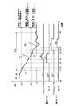
- FIG. 3 is a diagram for explaining two drive modes (first mode and second mode) during the engine starting operation in the present embodiment.
- the horizontal axis represents time
- the vertical axis represents the rotational speed Ne of the engine 100 and the driving state of the actuator 232 and the motor 220 in the first mode and the second mode.
- a stop request for the engine 100 is generated, and the engine 100 is stopped (fuel injection and ignition are stopped).
- the rotational speed Ne of the engine 100 gradually decreases as indicated by a solid curve W0, and finally the rotation of the engine 100 stops.
- the first region (region 1) is a case where the rotational speed Ne of the engine 100 is higher than the second reference value ⁇ 2, for example, the start condition is satisfied at the point P0 in FIG. 3, and a restart request is generated. It is the state that was done.
- This region 1 is a region where the engine 100 can be started without using the starter 200 by fuel injection and ignition operation because the rotational speed Ne of the engine 100 is sufficiently high. That is, it is an area where the engine 100 can return independently. Therefore, in the region 1, the driving of the starter 200 is restricted, more specifically, prohibited.
- the second reference value ⁇ 2 may be limited by the maximum rotation speed of the motor 220.
- the second region (region 2) is a case where the rotational speed Ne of the engine 100 is between the first reference value ⁇ 1 and the second reference value ⁇ 2, and the starting condition is satisfied at the point P1 in FIG. And a restart request is generated.
- This region 2 is a region where the engine 100 cannot return independently but the rotational speed Ne of the engine 100 is relatively high. In this area, the rotation mode is selected as described with reference to FIG.
- the motor 220 When a restart request for the engine 100 is generated at time t2, the motor 220 is first driven after a predetermined time has elapsed. As a result, the pinion gear 260 starts to rotate. At time t4, the actuator 232 is driven. When the ring gear 110 and the pinion gear 260 are engaged, the engine 100 is cranked, and the rotational speed Ne of the engine 100 increases as indicated by a dashed curve W1. Thereafter, when engine 100 resumes self-sustaining operation, driving of actuator 232 and motor 220 is stopped.
- the third region (region 3) is a case where the rotational speed Ne of the engine 100 is lower than the first reference value ⁇ 1, for example, the start condition is satisfied at the point P2 in FIG. 3, and a restart request is generated. It is the state that was done.
- This region 3 is a region where the rotation speed Ne of the engine 100 is low and the pinion gear 260 and the ring gear 110 can be engaged without synchronizing the pinion gear 260.
- the engagement mode is selected as described with reference to FIG.
- the actuator 232 When a restart request for the engine 100 is generated at time t5, the actuator 232 is first driven after a predetermined time has elapsed. Thereby, the pinion gear 260 is pushed out to the ring gear 110 side. Thereafter, the motor 220 is driven (time t7 in FIG. 3). As a result, the engine 100 is cranked, and the rotational speed Ne of the engine 100 increases as indicated by a dashed curve W2. Thereafter, when engine 100 resumes self-sustaining operation, driving of actuator 232 and motor 220 is stopped.
- the conventional starter cannot rotate the engine 100 independently.
- the time is shorter.
- the engine 100 can be restarted. Thereby, it is possible to reduce a sense of incongruity caused by a delay in engine restart for the driver.
- the voltage of the battery 120 that supplies power to the motor 220 can be temporarily reduced by driving the motor 200. Since the battery 120 supplies electric power to the auxiliary machines in addition to the motor 220, a decrease in the voltage of the battery 120 is not desirable.
- the present embodiment when the voltage of battery 120 falls below threshold value VS while driving motor 220, stop of engine 100 is restricted thereafter. More specifically, automatic stop of engine 100, that is, idling stop or economy running is prohibited.
- the frequency at which the engine 100 is automatically stopped may be reduced. For example, when the minimum value of the voltage of battery 120 while driving motor 220 is equal to or lower than threshold value VS, it is determined that the voltage of battery 120 has fallen below threshold value VS.
- the idling stop or economy running may be limited until the next IG-OFF signal is received, or may be limited until the memory of the ECU 300 is reset by replacing the battery 120.
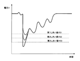
- the amount of decrease in the voltage of the battery 120 changes according to the engine speed Ne when the motor 220 is driven.
- the higher the engine speed Ne when driving the motor 220 the smaller the load on the motor 220. Therefore, the higher the engine speed Ne when driving the motor 220, the higher the voltage as shown in FIG. Can be reduced.
- different threshold values VS are used according to the engine rotational speed Ne when the motor 220 is driven. That is, when the actuator 232 and the motor 220 are controlled in the first mode, when the actuator 232 and the motor 220 are controlled in the second mode before the engine rotational speed Ne becomes zero, the engine rotational speed Ne is zero. In each case where the actuator 232 and the motor 220 are controlled in the second mode since then, different threshold values VS are used.
- the first threshold value VS1 is used.
- the second threshold value VS2 is used.
- the third threshold value VS3 is used.
- the first threshold value VS1 is higher than the second threshold value VS2.
- the second threshold value VS2 is higher than the third threshold value VS3.
- the first threshold value VS1, the second threshold value VS2, and the third threshold value VS3 are predetermined by the developer based on the results of experiments and simulations.
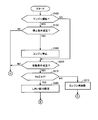
- FIGS. 6 and 7 a process executed by the ECU 300 to stop and start the engine 100 will be described.
- the flowcharts shown in FIGS. 6 and 7 are realized by executing a program stored in advance in ECU 300 at a predetermined cycle. Alternatively, for some steps, it is also possible to construct dedicated hardware (electronic circuit) and realize processing.
- step (hereinafter, step is abbreviated as S) 100 ECU 300 determines whether engine 100 is operating or not. If engine 100 is operating (YES in S100), ECU 300 determines in S102 whether the stop condition of engine 100 is satisfied. That is, it is determined whether to stop engine 100.
- ECU 300 stops engine 100 in S106 when the stop condition of engine 100 is satisfied (YES in S102). Therefore, fuel injection and combustion in engine 100 are stopped.
- ECU 300 determines whether or not the starting condition of engine 100 is satisfied. That is, it is determined whether or not engine 100 is to be started. If the start condition of engine 100 is not satisfied (NO in S200), the start operation of engine 100 is not necessary, so the process proceeds to S290, and ECU 300 sets the standby mode as the operation mode of starter 200. select.
- the ECU 300 determines in S216 whether the rotational speed Ne of the engine 100 is zero.
- ECU 300 When rotation speed Ne of engine 100 is zero (YES in S216), in S218, ECU 300 is the lowest of first threshold value VS1, second threshold value VS2, and third threshold value VS3.
- the third threshold value VS3 is selected as the threshold value VS to be compared with the voltage of the battery 120.
- engine rotation speed Ne is zero (YES in S220)
- engine rotation speed Ne is included in region 3 in FIG. 3, the process proceeds to S245, and ECU 300 causes starter 200 to operate.
- the engagement mode is selected as the mode.
- ECU 300 then outputs actuator 232 by outputting control signal SE1 and closing relay RY1. At this time, the motor 220 is not driven.
- ECU 300 restricts stop of engine 100 in S274.
- the stop of the engine 100 is restricted if the voltage of the battery 120 falls below the third threshold value VS3 while the motor 220 is being driven. If the stop of the engine 100 is restricted, the stop condition is not satisfied thereafter. Therefore, automatic stop of engine 100, that is, idling stop or economy running is restricted, and engine 100 is continuously operated.
- ECU 300 permits stop of engine 100 in S276.
- ECU 300 determines whether or not engine 100 has been started.
- the determination of the completion of the start of the engine 100 is made, for example, by determining whether or not the engine rotation speed is greater than a threshold value ⁇ indicating a self-sustained operation after a predetermined time has elapsed from the start of driving the motor 220. Good.
- the ECU 300 determines whether the rotational speed Ne of the engine 100 is equal to or less than a first reference value ⁇ 1 (0 ⁇ 1).
- ECU 300 When engine speed Ne is equal to or lower than first reference value ⁇ 1 (YES in S220), ECU 300 causes first threshold value VS1, second threshold value VS2, and third threshold value VS3 in S222. Among them, the second threshold value VS2 is selected as the threshold value VS to be compared with the voltage of the battery 120.
- engine speed Ne When engine speed Ne is equal to or lower than first reference value ⁇ 1 (YES in S220), engine speed Ne corresponds to region 3 in FIG. 3, the process proceeds to S245, and ECU 300 The engagement mode is selected as the operation mode of the starter 200. ECU 300 then outputs actuator 232 by outputting control signal SE1 and closing relay RY1. At this time, the motor 220 is not driven.
- ECU 300 restricts stop of engine 100 in S274.
- the rotational speed Ne of the engine 100 is greater than zero and less than or equal to the first reference value ⁇ 1 if the voltage of the battery 120 falls below the second threshold value VS2 while driving the motor 220, the engine 100 stops are limited.
- ECU 300 When engine speed Ne is greater than first reference value ⁇ 1 (NO in S220), ECU 300 causes first threshold value VS1, second threshold value VS2, and third threshold value VS3 in S224. Among them, the highest first threshold value VS1 is selected as the threshold value VS to be compared with the voltage of the battery 120.
- ECU 300 selects the rotation mode as the operation mode of starter 200 in S240. Then, ECU 300 drives motor 220 by outputting control signal SE2 and closing relay RY2. At this time, the actuator 232 is not driven.
- ECU300 selects all drive modes as an operation mode of starter 200 in S270. As a result, the actuator 232 is driven, the pinion gear 260 and the ring gear 110 are engaged, and the engine 100 is cranked.
- ECU 300 restricts stop of engine 100 in S274.
- the stop of the engine 100 is restricted if the voltage of the battery 120 falls below the first threshold value VS1 while the motor 220 is being driven.
- engine 100 is stopped when a predetermined stop condition is satisfied.
- a predetermined start condition When a predetermined start condition is satisfied, the motor 220 of the starter 200 is driven and the engine 100 is cranked. If the voltage of the battery 120 that supplies power to the motor 220 falls below the threshold value VS while the motor 220 is being driven, the stop of the engine 100 is restricted thereafter.
- the threshold value is higher as the engine speed Ne when driving the motor 220 is higher. Therefore, even if the amount of voltage decrease when the motor 220 is driven while the engine speed Ne is high is smaller than the amount of voltage decrease when the motor 220 is driven when the engine speed Ne is low, the battery 120 If the voltage is insufficient, the voltage of the battery 120 may fall below the threshold value VS. Therefore, thereafter, even if the stop condition is satisfied, engine 100 is continuously operated.
- the starter 202 in the present embodiment is different from the starter 200 in the first embodiment in that the pinion gear 260 is always engaged with the ring gear 110.
- the starter 202 in the present embodiment has a one-way clutch 270 instead of the actuator.
- the one-way clutch 270 is provided on the output member 250.
- the one-way clutch 270 allows the engine rotation speed Ne to be higher than the rotation speed of the motor 220.
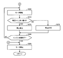
- FIGS. 9 and 10 processing executed by ECU 300 in order to stop and start engine 100 in the present embodiment will be described.
- the flowcharts shown in FIGS. 9 and 10 are realized by executing a program stored in advance in ECU 300 at a predetermined cycle.
- part of the processing can be realized by constructing dedicated hardware (electronic circuit).
- ECU 300 sets threshold value VS compared with the voltage of battery 120 to engine rotation speed Ne in S300. Set accordingly. For example, as shown in FIG. 11, the threshold value VS is set so as to increase as the engine speed Ne increases. More specifically, the threshold value VS is set so that the higher the engine speed Ne when the voltage is the lowest while the motor 220 is being driven, the higher the engine speed Ne. The threshold value VS may be set so as to increase as the engine rotational speed Ne increases when the start condition is satisfied. The threshold value VS may be set so as to increase as the engine rotational speed Ne at the start of driving the motor 220 increases. In addition, as the engine rotation speed Ne used for setting the threshold value VS, an appropriate rotation speed may be used as appropriate.
- ECU 300 drives motor 220 to crank engine 100 in S302.
- the engine 100 may be cranked by an alternator.
Landscapes
- Engineering & Computer Science (AREA)
- Chemical & Material Sciences (AREA)
- Combustion & Propulsion (AREA)
- Mechanical Engineering (AREA)
- General Engineering & Computer Science (AREA)
- Control Of Vehicle Engines Or Engines For Specific Uses (AREA)
Abstract
Description
図1は、車両10の全体ブロック図である。図1を参照して、車両10は、エンジン100と、バッテリ120と、スタータ200と、ECU300と、リレーRY1,RY2とを備える。また、スタータ200は、プランジャ210と、モータ220と、ソレノイド230と、連結部240と、出力部材250と、ピニオンギヤ260とを含む。
以下、図8を参照して、第2の実施の形態について説明する。本実施の形態におけるスタータ202は、第1の実施の形態におけるスタータ200と比較して、ピニオンギヤ260が常時リングギヤ110と係合している点で相違する。
Claims (13)
- 予め定められた停止条件が満たされたときに停止し、停止した後、予め定められた始動条件が満たされたときにモータ(220)によってクランキングされるエンジンの制御装置であって、
前記モータ(220)を駆動して前記エンジン(100)をクランキングしている間に、前記モータ(220)に電力を供給するバッテリ(120)の電圧がしきい値を下回った後は、前記エンジン(100)の停止を制限する制御ユニット(300)を備え、
前記しきい値は、前記モータ(220)を駆動するときの前記エンジン(100)の回転速度が高いほど高い、エンジンの制御装置。 - 前記エンジンには、クランク軸(111)に連結された第1のギヤ(110)と係合可能な第2のギヤ(260)と、駆動状態において、前記第2のギヤ(260)を前記第1のギヤ(110)と係合する位置まで移動させるアクチュエータ(232)とを含むスタータ(200)が設けられ、
前記モータ(220)は、前記第2のギヤ(260)を回転させ、
前記制御ユニット(300)は、前記アクチュエータ(232)の駆動に先立って前記モータ(220)を駆動させる第1のモードと、前記モータ(220)の駆動に先立って前記アクチュエータ(232)によって、前記第2のギヤ(260)を前記第1のギヤ(110)と係合させる第2のモードとを含み、
前記第2のモードで前記アクチュエータ(232)および前記モータ(220)が駆動されるときの前記エンジン(100)の回転速度よりも高い回転速度において、前記第1のモードで前記アクチュエータ(232)および前記モータ(220)が駆動される、請求項1に記載のエンジンの制御装置。 - 前記しきい値は、
前記第1のモードにおいて用いられるしきい値と、
前記第2のモードにおいて用いられるしきい値とを含み、
前記第1のモードにおいて用いられるしきい値は、前記第2のモードにおいて用いられるしきい値よりも高い、請求項2に記載のエンジンの制御装置。 - 前記始動条件が満たされたときに前記エンジン(100)の回転速度が零より大きく、かつ予め定められた回転速度以下であると、前記第2のモードで前記アクチュエータ(232)および前記モータ(220)が駆動され、
前記制御ユニット(300)は、前記第1のモードおよび前記第2のモードに加えて、 前記始動条件が満たされたときに前記エンジン(100)の回転速度が零であると、前記モータ(220)の駆動に先立って前記アクチュエータ(232)によって、前記第2のギヤ(260)を前記第1のギヤ(110)と係合させる第3のモードを含み、
前記しきい値は、
前記第1のモードにおいて用いられるしきい値と、
前記第2のモードにおいて用いられるしきい値と、
前記第3のモードにおいて用いられるしきい値とを含み、
前記第1のモードにおいて用いられるしきい値は、前記第2のモードにおいて用いられるしきい値よりも高く、
前記第2のモードにおいて用いられるしきい値は、前記第3のモードにおいて用いられるしきい値よりも高い、請求項2に記載のエンジンの制御装置。 - 前記始動条件が満たされたときに前記エンジン(100)の回転速度が零より大きく、かつ予め定められた回転速度以下であると、前記第2のモードで前記アクチュエータ(232)および前記モータ(220)が駆動され、
前記制御ユニット(300)は、前記第1のモードおよび前記第2のモードに加えて、 前記始動条件が満たされたときに前記エンジン(100)の回転速度が零であると、前記モータ(220)の駆動に先立って前記アクチュエータ(232)によって、前記第2のギヤ(260)を前記第1のギヤ(110)と係合させる第3のモードとを含み、
前記しきい値は、
前記第2のモードにおいて用いられるしきい値と、
前記第3のモードにおいて用いられるしきい値とを含み、
前記第2のモードにおいて用いられるしきい値は、前記第3のモードにおいて用いられるしきい値よりも高い、請求項2に記載のエンジンの制御装置。 - 前記始動条件が満たされたときに前記エンジン(100)の回転速度が零より大きく、かつ予め定められた回転速度以下であると、前記第2のモードで前記アクチュエータ(232)および前記モータ(220)が駆動され、
前記制御ユニット(300)は、前記第1のモードおよび前記第2のモードに加えて、 前記始動条件が満たされたときに前記エンジン(100)の回転速度が零であると、前記モータ(220)の駆動に先立って前記アクチュエータ(232)によって、前記第2のギヤ(260)を前記第1のギヤ(110)と係合させる第3のモードとを含み、
前記しきい値は、
前記第1のモードにおいて用いられるしきい値と、
前記第3のモードにおいて用いられるしきい値とを含み、
前記第1のモードにおいて用いられるしきい値は、前記第3のモードにおいて用いられるしきい値よりも高い、請求項2に記載のエンジンの制御装置。 - 予め定められた停止条件が満たされたときに停止し、停止した後、予め定められた始動条件が満たされたときにモータ(220)によってクランキングされるエンジンの制御方法であって、
予め定められた始動条件が満たされたときに前記モータ(220)を駆動して前記エンジン(100)をクランキングしている間に、前記モータ(220)に電力を供給するバッテリ(120)の電圧がしきい値を下回った後は、前記エンジンの(100)の停止を制限するステップを備え、
前記しきい値は、前記モータ(220)を駆動するときの前記エンジン(100)の回転速度が高いほど高い、エンジンの制御方法。 - 前記エンジンには、クランク軸(111)に連結された第1のギヤ(110)と係合可能な第2のギヤ(260)と、駆動状態において、前記第2のギヤ(260)を前記第1のギヤ(110)と係合する位置まで移動させるアクチュエータ(232)とを含むスタータ(200)が設けられ、
前記モータ(220)は、前記第2のギヤ(260)を回転させ、
前記第2のモードで前記アクチュエータ(232)および前記モータ(220)が駆動されるときの前記エンジン(100)の回転速度よりも高い回転速度において、前記第1のモードで前記アクチュエータ(232)および前記モータ(220)が駆動される、請求項7に記載のエンジンの制御方法。 - 前記しきい値は、
前記第1のモードにおいて用いられるしきい値と、
前記第2のモードにおいて用いられるしきい値とを含み、
前記第1のモードにおいて用いられるしきい値は、前記第2のモードにおいて用いられるしきい値よりも高い、請求項8に記載のエンジンの制御方法。 - 前記第2のモードで前記アクチュエータ(232)および前記モータ(220)を駆動するステップは、前記始動条件が満たされたときに前記エンジン(100)の回転速度が零より大きく、かつ予め定められた回転速度以下であると、前記第2のモードで前記アクチュエータ(232)および前記モータ(220)を駆動するステップを含み、
前記制御方法は、前記始動条件が満たされたときに前記エンジン(100)の回転速度が零であると、前記モータ(220)の駆動に先立って前記アクチュエータ(232)によって、前記第2のギヤ(260)を前記第1のギヤ(110)と係合させる第3のモードで前記アクチュエータ(232)および前記モータ(220)を駆動するステップをさらに備え、
前記しきい値は、
前記第1のモードにおいて用いられるしきい値と、
前記第2のモードにおいて用いられるしきい値と、
前記第3のモードにおいて用いられるしきい値とを含み、
前記第1のモードにおいて用いられるしきい値は、前記第2のモードにおいて用いられるしきい値よりも高く、
前記第2のモードにおいて用いられるしきい値は、前記第3のモードにおいて用いられるしきい値よりも高い、請求項8に記載のエンジンの制御方法。 - 前記第2のモードで前記アクチュエータ(232)および前記モータ(220)を駆動するステップは、前記始動条件が満たされたときに前記エンジン(100)の回転速度が零より大きく、かつ予め定められた回転速度以下であると、前記第2のモードで前記アクチュエータ(232)および前記モータ(220)を駆動するステップを含み、
前記制御方法は、前記始動条件が満たされたときに前記エンジン(100)の回転速度が零であると、前記モータ(220)の駆動に先立って前記アクチュエータ(232)によって、前記第2のギヤ(260)を前記第1のギヤ(110)と係合させる第3のモードで前記アクチュエータ(232)および前記モータ(220)を駆動するステップをさらに備え、
前記しきい値は、
前記第2のモードにおいて用いられるしきい値と、
前記第3のモードにおいて用いられるしきい値とを含み、
前記第2のモードにおいて用いられるしきい値は、前記第3のモードにおいて用いられるしきい値よりも高い、請求項8に記載のエンジンの制御方法。 - 前記第2のモードで前記アクチュエータ(232)および前記モータ(220)を駆動するステップは、前記始動条件が満たされたときに前記エンジン(100)の回転速度が零より大きく、かつ予め定められた回転速度以下であると、前記第2のモードで前記アクチュエータ(232)および前記モータ(220)を駆動するステップを含み、
前記制御方法は、前記始動条件が満たされたときに前記エンジン(100)の回転速度が零であると、前記モータ(220)の駆動に先立って前記アクチュエータ(232)によって、前記第2のギヤ(260)を前記第1のギヤ(110)と係合させる第3のモードで前記アクチュエータ(232)および前記モータ(220)を駆動するステップをさらに備え、
前記しきい値は、
前記第1のモードにおいて用いられるしきい値と、
前記第3のモードにおいて用いられるしきい値とを含み、
前記第1のモードにおいて用いられるしきい値は、前記第3のモードにおいて用いられるしきい値よりも高い、請求項8に記載のエンジンの制御方法。 - 予め定められた停止条件が満たされたときに停止し、停止した後、予め定められた始動条件が満たされたときにモータ(220)によってクランキングされるエンジン(100)と、
前記モータ(220)を駆動して前記エンジン(100)をクランキングしている間に、前記モータ(220)に電力を供給するバッテリ(120)の電圧がしきい値を下回った後は、前記エンジンの(100)の停止を制限する制御ユニット(300)を備え、
前記しきい値は、前記モータ(220)を駆動するときの前記エンジン(100)の回転速度が高いほど高い、車両。
Priority Applications (5)
| Application Number | Priority Date | Filing Date | Title |
|---|---|---|---|
| CN201180041780.9A CN103354869B (zh) | 2011-02-18 | 2011-02-18 | 发动机的控制装置、控制方法及车辆 |
| PCT/JP2011/053511 WO2012111143A1 (ja) | 2011-02-18 | 2011-02-18 | エンジンの制御装置および制御方法、ならびに車両 |
| DE112011102633.1T DE112011102633B4 (de) | 2011-02-18 | 2011-02-18 | Steuervorrichtung für Verbrennungsmotor |
| JP2012556327A JP5288070B2 (ja) | 2011-02-18 | 2011-02-18 | エンジンの制御装置および制御方法、ならびに車両 |
| US13/818,721 US8706387B2 (en) | 2011-02-18 | 2011-02-18 | Control device and control method for engine, and vehicle |
Applications Claiming Priority (1)
| Application Number | Priority Date | Filing Date | Title |
|---|---|---|---|
| PCT/JP2011/053511 WO2012111143A1 (ja) | 2011-02-18 | 2011-02-18 | エンジンの制御装置および制御方法、ならびに車両 |
Publications (1)
| Publication Number | Publication Date |
|---|---|
| WO2012111143A1 true WO2012111143A1 (ja) | 2012-08-23 |
Family
ID=46672104
Family Applications (1)
| Application Number | Title | Priority Date | Filing Date |
|---|---|---|---|
| PCT/JP2011/053511 Ceased WO2012111143A1 (ja) | 2011-02-18 | 2011-02-18 | エンジンの制御装置および制御方法、ならびに車両 |
Country Status (5)
| Country | Link |
|---|---|
| US (1) | US8706387B2 (ja) |
| JP (1) | JP5288070B2 (ja) |
| CN (1) | CN103354869B (ja) |
| DE (1) | DE112011102633B4 (ja) |
| WO (1) | WO2012111143A1 (ja) |
Cited By (1)
| Publication number | Priority date | Publication date | Assignee | Title |
|---|---|---|---|---|
| JP2019031604A (ja) * | 2017-08-07 | 2019-02-28 | 信一郎 礒部 | 蛍光色素 |
Families Citing this family (4)
| Publication number | Priority date | Publication date | Assignee | Title |
|---|---|---|---|---|
| US9834194B2 (en) * | 2011-08-08 | 2017-12-05 | Ford Global Technologies, Llc | Method and system for enabling electrical loads during an engine auto start |
| WO2013074852A1 (en) * | 2011-11-15 | 2013-05-23 | Remy Technologies, Llc | Starter system |
| CN115596589A (zh) * | 2021-07-08 | 2023-01-13 | 北京福田康明斯发动机有限公司(Cn) | 一种起动机的起动机保护方法、保护系统及保护装置 |
| JP7601044B2 (ja) * | 2022-04-01 | 2024-12-17 | トヨタ自動車株式会社 | 車両の制御装置 |
Citations (4)
| Publication number | Priority date | Publication date | Assignee | Title |
|---|---|---|---|---|
| JPH1047105A (ja) * | 1996-07-31 | 1998-02-17 | Suzuki Motor Corp | エンジンの自動始動停止装置 |
| JP2008114752A (ja) * | 2006-11-06 | 2008-05-22 | Toyota Motor Corp | ハイブリッド車両のエンジン制御装置及びハイブリッド車両のエンジン制御方法 |
| JP2008291661A (ja) * | 2007-05-22 | 2008-12-04 | Mazda Motor Corp | 車両用エンジンの制御装置 |
| JP2010236533A (ja) * | 2008-09-02 | 2010-10-21 | Denso Corp | エンジン自動停止始動制御装置 |
Family Cites Families (3)
| Publication number | Priority date | Publication date | Assignee | Title |
|---|---|---|---|---|
| FR2795770B1 (fr) * | 1999-06-30 | 2001-09-21 | Valeo Equip Electr Moteur | Procedes et systemes pour la commande automatique de la coupure et du redemarrage d'un moteur thermique d'un vehicule lors d'immobilisations temporaires de celui-ci |
| JP5026362B2 (ja) | 2008-07-17 | 2012-09-12 | 株式会社日本自動車部品総合研究所 | 内燃機関の自動停止始動装置 |
| JP5105032B2 (ja) * | 2011-04-08 | 2012-12-19 | トヨタ自動車株式会社 | スタータの制御装置および制御方法、ならびに車両 |
-
2011
- 2011-02-18 JP JP2012556327A patent/JP5288070B2/ja not_active Expired - Fee Related
- 2011-02-18 US US13/818,721 patent/US8706387B2/en active Active
- 2011-02-18 DE DE112011102633.1T patent/DE112011102633B4/de not_active Expired - Fee Related
- 2011-02-18 CN CN201180041780.9A patent/CN103354869B/zh not_active Expired - Fee Related
- 2011-02-18 WO PCT/JP2011/053511 patent/WO2012111143A1/ja not_active Ceased
Patent Citations (4)
| Publication number | Priority date | Publication date | Assignee | Title |
|---|---|---|---|---|
| JPH1047105A (ja) * | 1996-07-31 | 1998-02-17 | Suzuki Motor Corp | エンジンの自動始動停止装置 |
| JP2008114752A (ja) * | 2006-11-06 | 2008-05-22 | Toyota Motor Corp | ハイブリッド車両のエンジン制御装置及びハイブリッド車両のエンジン制御方法 |
| JP2008291661A (ja) * | 2007-05-22 | 2008-12-04 | Mazda Motor Corp | 車両用エンジンの制御装置 |
| JP2010236533A (ja) * | 2008-09-02 | 2010-10-21 | Denso Corp | エンジン自動停止始動制御装置 |
Cited By (2)
| Publication number | Priority date | Publication date | Assignee | Title |
|---|---|---|---|---|
| JP2019031604A (ja) * | 2017-08-07 | 2019-02-28 | 信一郎 礒部 | 蛍光色素 |
| JP7045752B2 (ja) | 2017-08-07 | 2022-04-01 | 信一郎 礒部 | 蛍光色素 |
Also Published As
| Publication number | Publication date |
|---|---|
| JP5288070B2 (ja) | 2013-09-11 |
| US20130158842A1 (en) | 2013-06-20 |
| CN103354869B (zh) | 2015-04-01 |
| DE112011102633B4 (de) | 2016-06-16 |
| DE112011102633T5 (de) | 2013-05-08 |
| US8706387B2 (en) | 2014-04-22 |
| CN103354869A (zh) | 2013-10-16 |
| JPWO2012111143A1 (ja) | 2014-07-03 |
Similar Documents
| Publication | Publication Date | Title |
|---|---|---|
| JP5105032B2 (ja) | スタータの制御装置および制御方法、ならびに車両 | |
| JP5056988B2 (ja) | エンジンの始動装置およびエンジンの始動方法 | |
| JP5170347B1 (ja) | エンジンの始動装置および制御方法 | |
| JP5316715B2 (ja) | スタータの制御装置、スタータの制御方法およびエンジンの始動装置 | |
| WO2012011167A1 (ja) | エンジンの始動装置およびエンジンの始動方法 | |
| JP5224005B2 (ja) | スタータの制御装置、スタータの制御方法およびエンジンの始動装置 | |
| JP5288070B2 (ja) | エンジンの制御装置および制御方法、ならびに車両 | |
| JP5644843B2 (ja) | 車両の制御装置 | |
| WO2012008045A1 (ja) | エンジンの始動装置およびそれを搭載する車両 | |
| JP5321746B2 (ja) | スタータの制御装置およびスタータの制御方法 | |
| JP5110231B2 (ja) | スタータの制御装置、エンジンの始動装置、ならびに車両 | |
| JP5316734B2 (ja) | スタータの制御装置および制御方法、ならびに車両 | |
| WO2012131942A1 (ja) | スタータの制御装置および制御方法、ならびに車両 | |
| JP5454402B2 (ja) | スタータの制御装置 | |
| JP2012021499A (ja) | スタータ | |
| JP2012021495A (ja) | エンジンの始動装置およびそれを搭載する車両 | |
| JP2012021496A (ja) | エンジンの始動装置およびそれを搭載する車両 |
Legal Events
| Date | Code | Title | Description |
|---|---|---|---|
| 121 | Ep: the epo has been informed by wipo that ep was designated in this application |
Ref document number: 11858701 Country of ref document: EP Kind code of ref document: A1 |
|
| WWE | Wipo information: entry into national phase |
Ref document number: 2012556327 Country of ref document: JP |
|
| WWE | Wipo information: entry into national phase |
Ref document number: 13818721 Country of ref document: US |
|
| WWE | Wipo information: entry into national phase |
Ref document number: 112011102633 Country of ref document: DE Ref document number: 1120111026331 Country of ref document: DE |
|
| 122 | Ep: pct application non-entry in european phase |
Ref document number: 11858701 Country of ref document: EP Kind code of ref document: A1 |