WO2012108228A1 - ファインダ装置及びカメラ - Google Patents
ファインダ装置及びカメラ Download PDFInfo
- Publication number
- WO2012108228A1 WO2012108228A1 PCT/JP2012/050742 JP2012050742W WO2012108228A1 WO 2012108228 A1 WO2012108228 A1 WO 2012108228A1 JP 2012050742 W JP2012050742 W JP 2012050742W WO 2012108228 A1 WO2012108228 A1 WO 2012108228A1
- Authority
- WO
- WIPO (PCT)
- Prior art keywords
- light shielding
- shielding plate
- optical system
- finder device
- light
- Prior art date
- Legal status (The legal status is an assumption and is not a legal conclusion. Google has not performed a legal analysis and makes no representation as to the accuracy of the status listed.)
- Ceased
Links
Images



Classifications
-
- G—PHYSICS
- G03—PHOTOGRAPHY; CINEMATOGRAPHY; ANALOGOUS TECHNIQUES USING WAVES OTHER THAN OPTICAL WAVES; ELECTROGRAPHY; HOLOGRAPHY
- G03B—APPARATUS OR ARRANGEMENTS FOR TAKING PHOTOGRAPHS OR FOR PROJECTING OR VIEWING THEM; APPARATUS OR ARRANGEMENTS EMPLOYING ANALOGOUS TECHNIQUES USING WAVES OTHER THAN OPTICAL WAVES; ACCESSORIES THEREFOR
- G03B13/00—Viewfinders; Focusing aids for cameras; Means for focusing for cameras; Autofocus systems for cameras
- G03B13/02—Viewfinders
-
- G—PHYSICS
- G03—PHOTOGRAPHY; CINEMATOGRAPHY; ANALOGOUS TECHNIQUES USING WAVES OTHER THAN OPTICAL WAVES; ELECTROGRAPHY; HOLOGRAPHY
- G03B—APPARATUS OR ARRANGEMENTS FOR TAKING PHOTOGRAPHS OR FOR PROJECTING OR VIEWING THEM; APPARATUS OR ARRANGEMENTS EMPLOYING ANALOGOUS TECHNIQUES USING WAVES OTHER THAN OPTICAL WAVES; ACCESSORIES THEREFOR
- G03B11/00—Filters or other obturators specially adapted for photographic purposes
- G03B11/04—Hoods or caps for eliminating unwanted light from lenses, viewfinders or focusing aids
- G03B11/046—Hoods or caps for eliminating unwanted light from lenses, viewfinders or focusing aids for viewfinders or eyepieces
Definitions
- the present invention relates to a finder device and a camera.
- an optical viewfinder ODF: Optical Finder
- EMF Electric View Finder
- OVF and EVF are switched, and one image is selectively observed.
- a captured image by EVF is superimposed on a subject image by OVF and observed.
- the above-described finder device is provided with a shielding plate.
- the shielding plate functions as a shutter that allows light to enter the OVF when in the open state and blocks light when the shielding plate is in the closed state. .
- the photographer can observe only the image captured by the EVF by opening the shielding plate and observing the subject using the OVF, and blocking the incident light to the OVF by closing the shielding plate. it can.
- the light shielding plate When observing only the captured image of the EVF with the light shielding plate closed, the light shielding plate may open due to an external impact or the like. Further, the light shielding plate may open even when the power of the finder apparatus is turned off. Furthermore, when the light shielding plate is opened and the captured image by EVF is superimposed on the subject image by OVF for observation, the light shielding plate may be closed due to an external impact or the like. It is difficult for the photographer to move the shading plate unintentionally in this way.
- the present invention is a finder apparatus having an optical system for optically observing a subject, A case provided with the optical system; A light shielding plate that is linearly movable between a light shielding position that is inserted into the optical system and blocks a light beam from a subject, and a retreat position that does not block the light beam; A drive member for moving the light shielding plate between the light shielding position and the retracted position; The drive member engages with the light shielding plate and rotates with respect to an axis perpendicular to a plane on which the light shielding plate exists, and the light shielding plate according to the rotation of the rotating portion.
- the finder device is provided with a stopper for restricting the movement of the light shielding plate.
- the present invention also provides a finder device as described above, And an imaging unit that captures an image in a range substantially equivalent to the visual field range of the optical system.
- FIG. 1 is a block diagram schematically showing an example of a viewfinder device and a camera for explaining an embodiment of the present invention.
- FIG. 1 shows an example of a viewfinder device and a camera for explaining an embodiment of the present invention.
- the camera 1 includes an imaging unit 2, a viewfinder device 3, an operation unit 4, and a control unit 5.
- the imaging unit 2 processes the image data by processing the CCD image sensor 10, the imaging optical system 11 that forms an optical image of the subject on the light receiving surface of the CCD image sensor 10, and the signal output from the CCD image sensor 10.
- a signal processing circuit 12 to be generated and an image memory 13 for storing image data generated by the signal processing circuit 12 are configured.
- the viewfinder device 3 includes a first optical system 20 for optically observing a subject, a liquid crystal display (LCD) 21, and an image displayed on the LCD 21 in the optical path of the first optical system 20. And a second optical system 22 for guiding.
- a first optical system 20 for optically observing a subject
- LCD liquid crystal display
- second optical system 22 for guiding.
- the first optical system 20 includes an objective lens 30, a diopter adjusting lens 31 for adjusting the diopter of the finder, and an eyepiece 32.
- the second optical system 22 guides the target lens 33 for focusing on the display panel 23 (see FIG. 2) of the LCD 21 and the image displayed on the display panel 23 to the optical path of the first optical system 20. And a cube-shaped half mirror 34.
- the OVF is configured by the first optical system 20
- the EVF is configured by the LCD 21 and the second optical system 22, the diopter adjustment lens 31, and the eyepiece lens 32.
- the operation unit 4 instructs the operation of the camera 1 and performs various settings. For example, the operation unit 4 instructs the imaging unit 2 to perform imaging, and switches or uses OVF and EVF in the finder device 3 together. Is set.
- the control unit 5 drives each unit of the camera 1 in response to an operation on the operation unit 4 and changes the setting.
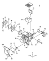
- FIG. 2 is an exploded view of the finder device 3, and FIG. 3 shows the first optical system 20 and the second optical system 22.
- the finder device 3 has a case 40 in which the first optical system 20, the LCD 21, and the second optical system 22 are assembled.
- the objective lens 30, the diopter adjustment lens 31, and the eyepiece lens 32 constituting the first optical system 20 are held in the case 40 in a state where their optical axes are aligned with each other.
- the optical axis X of the first optical system 20 is disposed along the x-axis direction.
- the case 40 is provided with a pair of guide shafts 41 extending in parallel with the optical axis of the first optical system 20.
- the diopter adjustment lens 31 is supported by a pair of guide shafts 41, and moves back and forth along the pair of guide shafts 41 in conjunction with the rotation operation of the diopter adjustment dial 71 provided on one side surface of the case 40. Moved. Thereby, the diopter of the finder is adjusted.
- the half mirror 34 constituting the second optical system 22 is disposed between the objective lens 30 and the diopter adjustment lens 31 and is held by the case 40.
- the target lens 33 which comprises the 2nd optical system 22 is the direction (In the example of illustration, the optical axis of the 1st optical system 20 extended in a x direction) which cross
- the optical axis Y of the second optical system 22 intersects the optical axis X of the first optical system 20 in the half mirror 34.
- the LCD 21 is disposed on an extension of the optical axis Y of the second optical system 22, and the case 40 is provided with a support portion 42 that supports the LCD 21.
- the support part 42 has a reference plane orthogonal to the optical axis Y, and the LCD 21 is supported by the support part 42 so that the position and orientation relative to the optical axis Y can be adjusted on this reference plane.
- a holding member 43 is attached to the support portion 42, and the LCD 21 is held between the reference surface of the support portion 42 and the holding member 43.
- the light incident on the objective lens 30 travels along the optical axis X of the first optical system 20, passes through the half mirror 34 and the diopter adjustment lens 31, and is emitted from the eyepiece lens 32.
- the light emitted from the display panel 23 of the LCD 21 travels along the optical axis Y of the second optical system 22, passes through the target lens 33 and enters the half mirror 34.
- the light is reflected in the direction along the optical axis X of the optical system 20 and guided into the optical path of the first optical system 20.
- the light passes through the diopter adjustment lens 31 and is emitted from the eyepiece lens 32.
- the viewfinder device 3 further includes a light shielding plate 50 for blocking the incidence of light on the objective lens 30 and a drive mechanism for moving the light shielding plate 50 so that the objective lens 30 is exposed and concealed. .
- the front wall 46 of the case 40 holding the objective lens 30 is provided with a pair of guides 47 extending in a predetermined direction (z direction in the illustrated example).
- the guide 47 is disposed on the front wall portion 46 and is supported so as to be linearly movable along the guide 47 in the z direction.
- a holding plate 56 is attached to the front wall portion 46, and the light shielding plate 50 is sandwiched and held between the holding plate 56 and the front wall portion 46 so as to be linearly movable.
- the light-shielding plate 50 moves linearly between the light-shielding position that blocks the light beam incident on the objective lens 30 and the retreat position that does not block the light beam incident on the objective lens 30 by the drive mechanism.
- the drive mechanism is composed of a lever 51 and a motor 52 for rotating the lever 51.
- the lever 51 has a rotation shaft 53 connected to the motor 52 and an engagement pin 54 provided at a position separated from the rotation shaft 53.
- the light shielding plate 50 is formed with a long hole 55 extending in a direction intersecting the moving direction (y direction in the illustrated example), and the engaging pin 54 of the lever 51 is long in the long hole 55.
- the long hole 55 is engaged so as to be movable in the extending direction of the hole 55.
- the holding plate 56 has a window 56a and a groove 58 formed therein.
- the window 56a is an opening through which light incident on the objective lens 30 passes, and has a substantially section shape when viewed in the x direction in FIG.
- the window 56a is closed when the light shielding plate 50 is in the light shielding position, and is opened when the light shielding plate 50 is in the retracted position.
- the groove 58 is formed in a substantially arc shape along the arc trajectory of the engagement pin 54 when the lever 51 is rotated.
- the groove 58 is located in a range corresponding to a range in which the lever 51 can rotate.
- the holding plate 56 includes a stopper that restricts the movement of the light shielding plate 50 at the light shielding position and the retracted position.
- the light shielding plate 50 In a state where the engagement pin 54 of the lever 51 is located below the rotation shaft 53 and at one end of the long hole 55 of the light shielding plate 50, the light shielding plate 50 is located on the lower side in the moving range. The objective lens 30 is completely exposed (FIG. 4C).
- the raising / lowering operation of the light shielding plate 50 is controlled by the control unit 5.
- the control unit 5 drives the motor 52 to lower the light shielding plate 50.
- the objective lens 30 is exposed and light enters the first optical system 20, and an optical image can be observed.
- the control unit 5 drives the motor 52 to raise the light shielding plate 50.
- the objective lens 30 is concealed so that the light incident on the first optical system 20 is blocked, and only the display image can be observed.
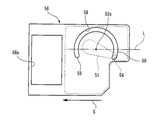
- FIG. 5 shows the holding plate 56 of the finder device 3 of FIG.
- the direction in which the light shielding plate moves linearly is indicated by an arrow S
- the axis center of the rotation shaft 53 of the lever 51 is 53c.
- L be a virtual line that is parallel to the moving direction S of the light shielding plate 50 and passes through the axis 53c.
- the groove 58 includes a position intersecting the imaginary line L, and is formed over a range of a predetermined center angle at the same radial distance from the axial center 53c. That is, when the engaging pin 54 of the lever 51 slides along the groove 58, the arc trajectory of the engaging pin intersects the imaginary line L.
- the groove 58 has an extension 59 extending along the circular arc path beyond the intersection point between the intersection point of the arc trajectory of the engagement pin 54 and the virtual line L and the end of the groove 58.
- an extension 59 extending from each of the positions intersecting the virtual line L to the end functions as a stopper.
- the engagement pin 54 is positioned on one extension 59 of the groove 58.
- the engagement pin 54 moves to the side opposite to the side where the light shielding plate 50 moves in the region from the extension 59 to the position overlapping the virtual line L. Then, even if a force in the direction S indicated by the arrow is applied to the light shielding plate 50 due to impact or vibration, the light shielding plate 50 is shielded by the engagement of the engaging pin 54 and the extension 59 of the groove 58. It can prevent moving to the position side.
- the groove 58 has an arc shape centered on the shaft center 53c, and its central angle is larger than 180 degrees.
- the extension portions 59 are formed at both ends of the groove 58 in a region beyond the intersection of the arcuate track of the engagement pin 54 and the virtual line L.
- the engaging pin 54 is located at the other extension 59 of the groove 58. In this case as well, it is possible to prevent the light shielding plate 50 from moving to the retracted position side by engaging the engaging pin 54 and the extension 59 of the groove 58.
- FIG. 6 shows the lever 51 of the finder device 3 of FIG.
- the lever 51 is a long member that rotates in a plane perpendicular to the shaft center 53c.
- An engaging pin 54 is provided at one end 52 a in the longitudinal direction of the lever 51.
- the other end 52b in the longitudinal direction has a function as a balancer for adjusting the balance of the entire lever 51 based on the weight on the one end 52a side.
- the center of gravity of the lever 51 is located on the axis of the axis center 53c. For this reason, it is possible to prevent the lever 51 from rotating due to the bias of its own weight balance, and when the lever 51 is rotated by the drive mechanism, the lever 51 can be stably rotated without rattling.
- the finder device 3 and the camera equipped with the finder device 3 when only the captured image of the EVF is observed with the light shielding plate closed, the light shielding plate opens due to an external impact or the like. Can be suppressed. Further, it is possible to prevent the light shielding plate from being opened when the power of the finder apparatus is turned off. Further, when the light shielding plate is opened and the captured image by EVF is superimposed on the subject image by OVF for observation, it is possible to prevent the light shielding plate from being closed due to an external impact or the like. Therefore, the photographer is easy to handle because the shading plate does not move unintentionally.
- the stopper is provided on the holding plate, but the present invention is not limited to this.
- the stopper may be provided on a member other than the holding plate.
- the engaging pin of the lever is engaged with the groove, but the shape of the lever and the engaging pin are not limited to this.
- the lever rotates about an axis perpendicular to the plane on which the light shielding plate 50 exists, other shapes such as a disc shape and a semicircular shape can be applied. It is preferable to use a disk-shaped rotating member because the center of gravity of the rotating member can be easily located on the axis. If the rotation member is a lever, the space required for rotation can be minimized.
- the light shielding plate 50 is inserted into the first optical system 20 on the subject side relative to the objective lens 30 so as to block the light beam from the subject from entering the objective lens 30.
- the insertion position is not limited to this.
- the light shielding plate may be inserted into the first optical system 20 between the objective lens 30 and the half mirror 34.
- a finder apparatus having an optical system for optically observing a subject, A case provided with the optical system; A light shielding plate that is linearly movable between a light shielding position that is inserted into the optical system and blocks a light beam from a subject, and a retreat position that does not block the light beam; A drive member for moving the light shielding plate between the light shielding position and the retracted position; The drive member engages with the light shielding plate and rotates with respect to an axis perpendicular to a plane on which the light shielding plate exists, and the light shielding plate according to the rotation of the rotating portion.
- an engaging part for moving Assuming a virtual line passing through the axis that is parallel to the moving direction of the light shielding plate, the circular arc trajectory of the engaging portion when the rotating member is rotated is at a position that intersects the virtual line.
- a finder device provided with a stopper for restricting the movement of the light shielding plate.
- the finder device according to (2) The holding plate is formed along a circular arc track of the engaging portion when the rotating member is rotated, and a groove for guiding the engaging portion is formed, and the engaging portion slides in the groove.
- the groove has a circular arc shape centered on the axis, and the central angle of the circular arc shape is larger than 180 degrees.
- channel is a finder apparatus which has the extension part extended along the said circular arc track beyond the said intersection, between the intersection of the said virtual line and the said circular arc track, and the said edge part.
- the finder device according to any one of (1) to (5), A viewfinder device in which the center of gravity of the rotating member is located on the axis.
- the finder device according to any one of (1) to (6), A display unit capable of displaying an image in a range substantially equivalent to the visual field range of the optical system; And a beam splitter for guiding the image displayed on the display unit to the optical system.
- the finder device according to any one of (1) to (7); An imaging unit that captures an image in a range substantially equivalent to a visual field range of the optical system.
- the finder apparatus and camera according to the present invention are useful when applied to cameras such as digital still cameras and digital video cameras.
- This application is based on Japanese Patent Application No. 2011-25507 filed on Feb. 8, 2011, the contents of which are incorporated herein by reference.
Landscapes
- Physics & Mathematics (AREA)
- General Physics & Mathematics (AREA)
- Viewfinders (AREA)
- Blocking Light For Cameras (AREA)
- Studio Devices (AREA)
Abstract
撮影者が扱い易いファインダ装置及びカメラを提供する。 ファインダ装置は、光学系が設けられたケースと、前記光学系に挿入されて被写体からの光束を遮断する遮光位置と、光束を遮らない退避位置との間で直線的に移動可能な遮光板と、遮光板を遮光位置と退避位置との間で移動させるための駆動部材と、を備え、駆動部材は、遮光板が存在する平面に対して垂直な軸を中心として回動する回動部材と、遮光板に係合し、回動部の回動に応じて該遮光板を移動させる係合部とを含み、遮光板の移動する方向と平行で、かつ、軸を通る仮想線を想定したとき、回動部材を回動したときの係合部の円弧軌道が仮想線と交差する位置に、遮光板の移動を規制するストッパが設けられている。
Description
本発明は、ファインダ装置及びカメラに関する。
デジタルスチルカメラやデジタルビデオカメラなどのカメラのファインダ装置として、被写体の光学像を観察する光学ビューファインダ(OVF:Optical View Finder)と、被写体を撮像して得られた撮像画像を液晶ディスプレイに表示して、これを観察する電子ビューファインダ(EVF:Electric View Finder)とを備えた、いわゆるハイブリッド型のファインダ装置が知られている(例えば、特許文献1参照)。
ハイブリッド型のファインダ装置においては、例えば、OVFとEVFとが切り換えられ、一方の像が選択的に観察される。また、OVFによる被写体像にEVFによる撮像画像が重畳されて観察される場合もある。
上記のファインダ装置には遮蔽板が設けられており、遮蔽板は、開状態とすることでOVFに対する光の入射を許容し、遮蔽板を閉状態とすることで光を遮断するシャッタとして機能する。これにより、撮影者は、遮蔽板を開いてOVFを利用して被写体を観察するとともに、遮蔽板を閉状態にしてOVFに対する入射光を遮断することで、EVFによる撮像画像のみを観察することができる。
遮光板を閉状態にしてEVFの撮像画像のみを観察する際に、外部からの衝撃などに起因して、遮光板が開いてしまう場合がある。また、ファインダ装置の電源をOFFにしている際にも、遮光板が開いてしまう場合がある。更に、遮光板を開状態にしてOVFによる被写体像にEVFによる撮像画像が重畳されて観察する場合に、外部からの衝撃などに起因して、遮光板が閉じてしまう場合がある。このように遮光板が意図せずに移動してしまうことは、撮影者にとって扱いづらい。
本発明は、撮影者が扱い易いファインダ装置及びカメラを提供することにある。
本発明は、被写体を光学的に観察するための光学系を有するファインダ装置であって、
前記光学系が設けられたケースと、
前記光学系に挿入されて被写体からの光束を遮断する遮光位置と、前記光束を遮らない退避位置との間で直線的に移動可能な遮光板と、
前記遮光板を前記遮光位置と前記退避位置との間で移動させるための駆動部材と、を備え、
前記駆動部材は、前記遮光板が存在する平面に対して垂直な軸を中心として回動する回動部材と、前記遮光板に係合し、前記回動部の回動に応じて該遮光板を移動させる係合部とを含み、
前記遮光板の移動する方向と平行で、かつ、前記軸を通る仮想線を想定したとき、前記回動部材を回動したときの前記係合部の円弧軌道が前記仮想線と交差する位置に、前記遮光板の移動を規制するストッパが設けられているファインダ装置である。
前記光学系が設けられたケースと、
前記光学系に挿入されて被写体からの光束を遮断する遮光位置と、前記光束を遮らない退避位置との間で直線的に移動可能な遮光板と、
前記遮光板を前記遮光位置と前記退避位置との間で移動させるための駆動部材と、を備え、
前記駆動部材は、前記遮光板が存在する平面に対して垂直な軸を中心として回動する回動部材と、前記遮光板に係合し、前記回動部の回動に応じて該遮光板を移動させる係合部とを含み、
前記遮光板の移動する方向と平行で、かつ、前記軸を通る仮想線を想定したとき、前記回動部材を回動したときの前記係合部の円弧軌道が前記仮想線と交差する位置に、前記遮光板の移動を規制するストッパが設けられているファインダ装置である。
また、本発明は、上述のファインダ装置と、
前記光学系の視野範囲とほぼ等価な範囲の画像を撮像する撮像部と、を備えるカメラである。
前記光学系の視野範囲とほぼ等価な範囲の画像を撮像する撮像部と、を備えるカメラである。
本発明によれば、撮影者が扱い易いファインダ装置及びカメラを提供できる。
図1は、本発明の実施形態を説明するための、ファインダ装置及びカメラの一例を示す。
カメラ1は、撮像部2と、ファインダ装置3と、操作部4と、制御部5と、を備えている。
撮像部2は、CCDイメージセンサ10と、このCCDイメージセンサ10の受光面に被写体の光学像を結像させる撮像光学系11と、CCDイメージセンサ10から出力される信号を処理して画像データを生成する信号処理回路12と、信号処理回路12によって生成された画像データを記憶する画像メモリ13とで構成されている。
ファインダ装置3は、被写体を光学的に観察するための第1の光学系20と、液晶ディスプレイ(LCD:Liquid Crystal Display)21と、LCD21に表示された画像を第1の光学系20の光路に導く第2の光学系22と、で構成されている。
第1の光学系20は、対物レンズ30と、ファインダの視度を調整するための視度調整レンズ31と、接眼レンズ32とで構成されている。また、第2の光学系22は、LCD21の表示パネル23(図2参照)に焦点を合わせるためのターゲットレンズ33と、表示パネル23に表示された画像を第1の光学系20の光路に導くためのキューブ型のハーフミラー34とで構成されている。第1の光学系20によりOVFが構成され、また、LCD21及び第2の光学系22、並びに視度調整レンズ31及び接眼レンズ32によりEVFが構成されている。
操作部4は、カメラ1の動作を指示し、また、各種の設定を行うためのものであって、例えば、撮像部2による撮像の指示や、ファインダ装置3におけるOVFとEVFとの切り替え若しくは併用の設定がなされる。
制御部5は、操作部4における操作に応答して、カメラ1の各部を駆動し、設定を変更する。
図2は、ファインダ装置3を分解して示し、図3は、第1の光学系20及び第2の光学系22を示す。
ファインダ装置3は、第1の光学系20、LCD21、及び第2の光学系22が組み付けられるケース40を有している。
第1の光学系20を構成する対物レンズ30、視度調整レンズ31、及び接眼レンズ32は、それらの光軸を互いに一致させた状態にケース40に保持されている。図示の例において、第1の光学系20の光軸Xはx軸方向に沿って配置される。
ケース40には、第1の光学系20の光軸と平行に延在する一対のガイド軸41が設けられている。視度調整レンズ31は、一対のガイド軸41に支持されており、ケース40の一方の側面部に設けられる視度調整ダイヤル71の回転操作に連動して、一対のガイド軸41に沿って前後移動される。それにより、ファインダの視度が調整される。
第2の光学系22を構成するハーフミラー34は、対物レンズ30と視度調整レンズ31との間に配置されて、ケース40に保持されている。そして、第2の光学系22を構成するターゲットレンズ33は、第1の光学系20の光軸Xと交差する方向(図示の例においては、x方向に延びる第1の光学系20の光軸Xに直交するy方向)からハーフミラー34を臨む位置に配置されて、ケース40に保持されている。第2の光学系22の光軸Yは、ハーフミラー34において第1の光学系20の光軸Xに交差する。
LCD21は、第2の光学系22の光軸Yの延長上に配置され、ケース40には、LCD21を支持する支持部42が設けられている。支持部42は、光軸Yと直交する基準面を有しており、LCD21は、この基準面上において光軸Yに対する位置及び姿勢を調整可能に支持部42に支持される。そして、支持部42には保持部材43が取付けられ、LCD21は、支持部42の基準面と保持部材43とによって挟まれて保持されている。
対物レンズ30に入射した光は、第1の光学系20の光軸Xに沿って進み、ハーフミラー34及び視度調整レンズ31を透過して、接眼レンズ32から出射される。また、LCD21の表示パネル23から出射された光は、第2の光学系22の光軸Yに沿って進み、ターゲットレンズ33を透過してハーフミラー34に入射し、ハーフミラー34によって第1の光学系20の光軸Xに沿う方向に反射されて第1の光学系20の光路内に導かれる。そして、視度調整レンズ31を透過して、接眼レンズ32から出射される。以上により、OVFによる光学像、及びEVFによる画像が、接眼レンズ32を覗く撮影者によって観察される。
なお、ハーフミラー34の代わりに、他のビームスプリッタを適用することもできる。
ファインダ装置3は、対物レンズ30への光の入射を遮るための遮光板50と、対物レンズ30を露呈させ、また隠蔽するように遮光板50を移動させる駆動機構と、を更に有している。
対物レンズ30を保持しているケース40の前壁部46には、所定の方向(図示の例ではz方向)に延在する一対のガイド47が設けられており、遮光板50は、これら一対のガイド47の間で前壁部46上に配置され、ガイド47に沿ってz方向に直線的に移動可能に支持されている。前壁部46には保持板56が取り付けられ、遮光板50は、直線的に移動可能に、この保持板56と前壁部46との間に挟まれて保持される。
すなわち、遮光板50は、駆動機構によって、対物レンズ30に入射する光束を遮断する遮光位置と、対物レンズ30に入射する光束を遮らない退避位置との間で直線的に移動する。
駆動機構は、レバー51と、レバー51を回動させるためのモータ52とで構成されている。レバー51は、モータ52に連結された回動軸53と、回動軸53から離間した位置に設けられた係合ピン54とを有している。遮光板50には、その移動方向と交差する方向(図示の例においてはy方向)に延在する長孔55が形成されており、レバー51の係合ピン54は、長孔55内において長孔55の延在方向に移動可能に、長孔55に係合している。
保持板56には、窓56aと、溝58とが形成されている。
窓56aは、対物レンズ30に入射する光が通過する開口であって、図2のx方向視において略区形状である。窓56aは、遮光板50が遮光位置にある場合には閉じた状態となり、また、遮光板50が退避位置にある場合には開いた状態となる。
溝58は、レバー51を回動したときの係合ピン54の円弧軌道に沿って略円弧状に形成されている。溝58は、レバー51が回動可能な範囲に相当する範囲に位置する。保持板56は、後述するように、遮光位置及び退避位置にある遮光板50が移動することを規制するストッパを含む。
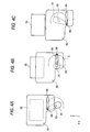
図4を参照して、駆動機構及び遮光板50の動作について説明する。
レバー51の係合ピン54が、回動軸53よりも上に位置し、かつ、遮光板50の長孔55の一端(図示の例においては左端)に位置している状態で、遮光板50は、その移動範囲における上側に位置しており、対物レンズ30は、遮光板50によって隠蔽されている(FIG.4A)。
モータ52が駆動されてレバー51が回動するのに伴って、レバー51の係合ピン54は、回動軸53を中心とする円弧軌道C上を移動する。その際、係合ピン54は、長孔55内をその延在方向にスライド移動しながら降下し、これに係合する遮光板50もまた降下する(FIG.4B)。
レバー51の係合ピン54が、回動軸53よりも下に位置し、かつ、遮光板50の長孔55の一端に位置している状態で、遮光板50は、その移動範囲における下側に位置しており、対物レンズ30は、完全に露呈している(FIG.4C)。
以上の遮光板50の昇降動作は、制御部5によって制御される。例えば、操作部4においてOVFによる光学像を観察するモードが選択された場合に、制御部5は、モータ52を駆動して遮光板50を降下させる。それにより、対物レンズ30が露呈して第1の光学系20に光が入射し、光学像が観察可能となる。また、EVFによる表示画像のみを観察するモードが選択された場合に、制御部5は、モータ52を駆動して遮光板50を上昇させる。それにより、対物レンズ30が隠蔽されて第1の光学系20への光の入射が遮られ、表示画像のみが観察可能となる。
図5は、図1のファインダ装置3の保持板56を示す。図5において、遮光板が直線的に移動する方向を矢印Sで示し、レバー51の回動軸53の軸中心を53cとする。仮に、遮光板50の移動する方向Sと平行で、かつ、軸53cを通る仮想線をLとする。溝58は、仮想線Lと交差する位置を含み、軸中心53cから同じ半径距離で、所定の中心角度の範囲にわたって形成されている。すなわち、溝58に沿ってレバー51の係合ピン54がスライドする際に、その係合ピンの円弧軌道が仮想線Lと交差する。そして、溝58は、係合ピン54の円弧軌道と仮想線Lとの交点から溝58の端部までの間に、前記交点を超えて円弧軌道に沿って延びる延長部59を有する。溝58において、仮想線Lと交差する位置のそれぞれから端部まで延びている延長部59がストッパとして機能する。
次にストッパの機能について説明する。
図5に示すように、遮光板50が退避位置にある場合、係合ピン54は、溝58の一方の延長部59に位置する。係合ピン54は、延長部59から仮想線Lに重なる位置までの領域では、遮光板50の移動する側とは反対側に移動する。すると、衝撃や振動などに起因して遮光板50に矢印で示す方向Sの力がかかっても、係合ピン54と溝58の延長部59とが係合することにより、遮光板50が遮蔽位置側に移動してしまうことを防止できる。
図5に示すように、遮光板50が退避位置にある場合、係合ピン54は、溝58の一方の延長部59に位置する。係合ピン54は、延長部59から仮想線Lに重なる位置までの領域では、遮光板50の移動する側とは反対側に移動する。すると、衝撃や振動などに起因して遮光板50に矢印で示す方向Sの力がかかっても、係合ピン54と溝58の延長部59とが係合することにより、遮光板50が遮蔽位置側に移動してしまうことを防止できる。
溝58は、軸中心53cを中心とする円弧形状であり、その中心角が180度より大きい。つまり、溝58の両端部は、係合ピン54の円弧軌道と仮想線Lとの交点を超えた領域で延長部59が形成されている。
図5には示さないが、同様に、遮光板50が遮蔽位置にある場合、係合ピン54は、溝58の他方の延長部59に位置する。この場合でも同様に、係合ピン54と溝58の延長部59とが係合することにより、遮光板50が退避位置側に移動してしまうことを防止できる。
図6は、図1のファインダ装置3のレバー51を示す。レバー51は、軸中心53cに対して垂直な平面において回動する長尺状の部材である。レバー51の長尺方向の一方の端部52aに係合ピン54が設けられている。長尺方向の他方の端部52bは、一方の端部52a側の重量に基づいて、レバー51全体のバランスを調整するためのバランサーとしての機能を有する。レバー51は、その重心が軸中心53cの軸上に位置する。このため、レバー51が自身の重量バランスの偏りによって、回動してしまうことを防止でき、また、駆動機構によってレバー51を回動させる場合に、ガタつきなく安定して回転させることができる。
このファインダ装置3及びこのファインダ装置3を備えたカメラによれば、遮光板を閉状態にしてEVFの撮像画像のみを観察する際に、外部からの衝撃などに起因して、遮光板が開いてしまうことを抑えられる。また、ファインダ装置の電源をOFFにしている際に、遮光板が開いてしまうことを抑えることができる。更に、遮光板を開状態にしてOVFによる被写体像にEVFによる撮像画像が重畳されて観察する場合に、外部からの衝撃などに起因して、遮光板が閉じてしまうことを抑えることができる。したがって、撮影者は、遮光板が意図せずに移動してしまうことがないため、扱い易い。
次に変形例について説明する。
上述の構成では、保持板にストッパを設けたが、これに限定されない。ストッパは、保持板以外の部材に設けられていてもよい。
上述の構成では、レバーの係合ピンが溝に係合しているが、レバーの形状や、係合ピンはこれに限定されない。レバーは、遮光板50が存在する平面に対して垂直な軸を中心として回動するものであれば、円盤状や、半円状などの他の形状を適用することができる。円盤状の回動部材を用いれば、回動部材の重心を軸上に位置させやすいため好ましい。回動部材をレバーとすれば、回動に必要なスペースを最小限にとどめることができる。
上述の構成では、遮光板50は、被写体からの光束が対物レンズ30に入射するのを遮断するように、対物レンズ30よりも被写体側で第1の光学系20に挿入されるが、遮光板の挿入位置はこれに限定されない。遮光板は、対物レンズ30とハーフミラー34との間で第1の光学系20に挿入されてもよい。
本明細書は次の事項を開示する。
(1) 被写体を光学的に観察するための光学系を有するファインダ装置であって、
前記光学系が設けられたケースと、
前記光学系に挿入されて被写体からの光束を遮断する遮光位置と、前記光束を遮らない退避位置との間で直線的に移動可能な遮光板と、
前記遮光板を前記遮光位置と前記退避位置との間で移動させるための駆動部材と、を備え、
前記駆動部材は、前記遮光板が存在する平面に対して垂直な軸を中心として回動する回動部材と、前記遮光板に係合し、前記回動部の回動に応じて該遮光板を移動させる係合部とを含み、
前記遮光板の移動する方向と平行で、かつ、前記軸を通る仮想線を想定したとき、前記回動部材を回動したときの前記係合部の円弧軌道が前記仮想線と交差する位置に、前記遮光板の移動を規制するストッパが設けられているファインダ装置。
(2) (1)に記載のファインダ装置であって、
前記直線的な移動が可能な状態に、前記遮光板を前記ケース側との間で保持する保持板を備え、
前記ストッパが、前記保持板に設けられているファインダ装置。
(3) (2)に記載のファインダ装置であって、
前記保持板には前記回動部材を回動したときの前記係合部の円弧軌道に沿って形成され、前記係合部を導く溝が形成され、前記溝における、前記係合部がスライドする方向における両方の端部に前記ストッパが設けられているファインダ装置。
(4) (3)に記載のファインダ装置であって、
前記溝は、前記軸を中心とする円弧形状であって、該円弧形状の中心角が180度より大きいファインダ装置。
(5) (4)に記載のファインダ装置であって、
前記溝は、前記仮想線と前記円弧軌道との交点から前記端部までの間に、前記交点を超えて前記円弧軌道に沿って延びる延長部を有するファインダ装置。
(6) (1)から(5)のいずれか1つに記載のファインダ装置であって、
前記回動部材の重心が、前記軸上に位置するファインダ装置。
(7) (1)から(6)のいずれか1つに記載のファインダ装置であって、
前記光学系の視野範囲とほぼ等価な範囲の画像を表示可能な表示部と、
前記表示部に表示された画像を前記光学系に導くためのビームスプリッタと、を備えるファインダ装置。
(8) (1)から(7)のいずれか1つに記載のファインダ装置と、
前記光学系の視野範囲とほぼ等価な範囲の画像を撮像する撮像部と、を備えるカメラ。
(1) 被写体を光学的に観察するための光学系を有するファインダ装置であって、
前記光学系が設けられたケースと、
前記光学系に挿入されて被写体からの光束を遮断する遮光位置と、前記光束を遮らない退避位置との間で直線的に移動可能な遮光板と、
前記遮光板を前記遮光位置と前記退避位置との間で移動させるための駆動部材と、を備え、
前記駆動部材は、前記遮光板が存在する平面に対して垂直な軸を中心として回動する回動部材と、前記遮光板に係合し、前記回動部の回動に応じて該遮光板を移動させる係合部とを含み、
前記遮光板の移動する方向と平行で、かつ、前記軸を通る仮想線を想定したとき、前記回動部材を回動したときの前記係合部の円弧軌道が前記仮想線と交差する位置に、前記遮光板の移動を規制するストッパが設けられているファインダ装置。
(2) (1)に記載のファインダ装置であって、
前記直線的な移動が可能な状態に、前記遮光板を前記ケース側との間で保持する保持板を備え、
前記ストッパが、前記保持板に設けられているファインダ装置。
(3) (2)に記載のファインダ装置であって、
前記保持板には前記回動部材を回動したときの前記係合部の円弧軌道に沿って形成され、前記係合部を導く溝が形成され、前記溝における、前記係合部がスライドする方向における両方の端部に前記ストッパが設けられているファインダ装置。
(4) (3)に記載のファインダ装置であって、
前記溝は、前記軸を中心とする円弧形状であって、該円弧形状の中心角が180度より大きいファインダ装置。
(5) (4)に記載のファインダ装置であって、
前記溝は、前記仮想線と前記円弧軌道との交点から前記端部までの間に、前記交点を超えて前記円弧軌道に沿って延びる延長部を有するファインダ装置。
(6) (1)から(5)のいずれか1つに記載のファインダ装置であって、
前記回動部材の重心が、前記軸上に位置するファインダ装置。
(7) (1)から(6)のいずれか1つに記載のファインダ装置であって、
前記光学系の視野範囲とほぼ等価な範囲の画像を表示可能な表示部と、
前記表示部に表示された画像を前記光学系に導くためのビームスプリッタと、を備えるファインダ装置。
(8) (1)から(7)のいずれか1つに記載のファインダ装置と、
前記光学系の視野範囲とほぼ等価な範囲の画像を撮像する撮像部と、を備えるカメラ。
本発明に係るファインダ装置及びカメラは、デジタルスチルカメラやデジタルビデオカメラなどのカメラに適用すると有用である。
本出願は、2011年2月8日出願の日本特許出願番号2011-25507に基づくものであり、その内容はここに参照として取り込まれる。
本出願は、2011年2月8日出願の日本特許出願番号2011-25507に基づくものであり、その内容はここに参照として取り込まれる。
1 カメラ
2 撮像部
3 ファインダ装置
4 操作部
5 制御部
20 第1の光学系
21 液晶ディスプレイ(表示部)
22 第2の光学系
30 対物レンズ
31 視度調整レンズ
32 接眼レンズ
33 ターゲットレンズ
34 ハーフミラー
40 ケース
50 遮光板
51 レバー
52 モータ
56 保持板
L 仮想線
2 撮像部
3 ファインダ装置
4 操作部
5 制御部
20 第1の光学系
21 液晶ディスプレイ(表示部)
22 第2の光学系
30 対物レンズ
31 視度調整レンズ
32 接眼レンズ
33 ターゲットレンズ
34 ハーフミラー
40 ケース
50 遮光板
51 レバー
52 モータ
56 保持板
L 仮想線
Claims (8)
- 被写体を光学的に観察するための光学系を有するファインダ装置であって、
前記光学系が設けられたケースと、
前記光学系に挿入されて被写体からの光束を遮断する遮光位置と、前記光束を遮らない退避位置との間で直線的に移動可能な遮光板と、
前記遮光板を前記遮光位置と前記退避位置との間で移動させるための駆動部材と、を備え、
前記駆動部材は、前記遮光板が存在する平面に対して垂直な軸を中心として回動する回動部材と、前記遮光板に係合し、前記回動部の回動に応じて該遮光板を移動させる係合部とを含み、
前記遮光板の移動する方向と平行で、かつ、前記軸を通る仮想線を想定したとき、前記回動部材を回動したときの前記係合部の円弧軌道が前記仮想線と交差する位置に、前記遮光板の移動を規制するストッパが設けられているファインダ装置。 - 請求項1に記載のファインダ装置であって、
前記直線的な移動が可能な状態に、前記遮光板を前記ケース側との間で保持する保持板を備え、
前記ストッパが、前記保持板に設けられているファインダ装置。 - 請求項2に記載のファインダ装置であって、
前記保持板には前記回動部材を回動したときの前記係合部の円弧軌道に沿って形成され、前記係合部を導く溝が形成され、前記溝における、前記係合部がスライドする方向における両方の端部に前記ストッパが設けられているファインダ装置。 - 請求項3に記載のファインダ装置であって、
前記溝は、前記軸を中心とする円弧形状であって、該円弧形状の中心角が180度より大きいファインダ装置。 - 請求項4に記載のファインダ装置であって、
前記溝は、前記仮想線と前記円弧軌道との交点から前記端部までの間に、前記交点を超えて前記円弧軌道に沿って延びる延長部を有するファインダ装置。 - 請求項1から5のいずれか1項に記載のファインダ装置であって、
前記回動部材の重心が、前記軸上に位置するファインダ装置。 - 請求項1から6のいずれか1項に記載のファインダ装置であって、
前記光学系の視野範囲とほぼ等価な範囲の画像を表示可能な表示部と、
前記表示部に表示された画像を前記光学系に導くためのビームスプリッタと、を備えるファインダ装置。 - 請求項1から7のいずれか1項に記載のファインダ装置と、
前記光学系の視野範囲とほぼ等価な範囲の画像を撮像する撮像部と、を備えるカメラ。
Applications Claiming Priority (2)
| Application Number | Priority Date | Filing Date | Title |
|---|---|---|---|
| JP2011025507A JP2014077813A (ja) | 2011-02-08 | 2011-02-08 | ファインダ装置及びカメラ |
| JP2011-025507 | 2011-02-08 |
Publications (1)
| Publication Number | Publication Date |
|---|---|
| WO2012108228A1 true WO2012108228A1 (ja) | 2012-08-16 |
Family
ID=46638447
Family Applications (1)
| Application Number | Title | Priority Date | Filing Date |
|---|---|---|---|
| PCT/JP2012/050742 Ceased WO2012108228A1 (ja) | 2011-02-08 | 2012-01-16 | ファインダ装置及びカメラ |
Country Status (2)
| Country | Link |
|---|---|
| JP (1) | JP2014077813A (ja) |
| WO (1) | WO2012108228A1 (ja) |
Citations (3)
| Publication number | Priority date | Publication date | Assignee | Title |
|---|---|---|---|---|
| JPH0618957A (ja) * | 1992-06-30 | 1994-01-28 | Nikon Corp | カメラの防振装置 |
| JP2001008067A (ja) * | 1999-05-27 | 2001-01-12 | Hewlett Packard Co <Hp> | 光学ビューファインダを介して像を表示するデジタルカメラシステムおよび方法 |
| JP2010193008A (ja) * | 2009-02-16 | 2010-09-02 | Canon Electronics Inc | 光量調節装置及びレンズバリア装置 |
-
2011
- 2011-02-08 JP JP2011025507A patent/JP2014077813A/ja not_active Withdrawn
-
2012
- 2012-01-16 WO PCT/JP2012/050742 patent/WO2012108228A1/ja not_active Ceased
Patent Citations (3)
| Publication number | Priority date | Publication date | Assignee | Title |
|---|---|---|---|---|
| JPH0618957A (ja) * | 1992-06-30 | 1994-01-28 | Nikon Corp | カメラの防振装置 |
| JP2001008067A (ja) * | 1999-05-27 | 2001-01-12 | Hewlett Packard Co <Hp> | 光学ビューファインダを介して像を表示するデジタルカメラシステムおよび方法 |
| JP2010193008A (ja) * | 2009-02-16 | 2010-09-02 | Canon Electronics Inc | 光量調節装置及びレンズバリア装置 |
Also Published As
| Publication number | Publication date |
|---|---|
| JP2014077813A (ja) | 2014-05-01 |
Similar Documents
| Publication | Publication Date | Title |
|---|---|---|
| JP5723488B2 (ja) | カメラおよびその動作制御方法 | |
| KR20180012688A (ko) | 카메라 모듈 및 이를 포함하는 휴대용 전자 기기 | |
| US20110286119A1 (en) | Lens barrel, imaging device and manufacturing method thereof | |
| KR20080061264A (ko) | 촬상 장치 | |
| US20170353638A1 (en) | Device with split imaging system | |
| KR20100007263A (ko) | 디지털 촬영장치, 제어방법 및 제어방법을 실행시키기 위한프로그램을 저장한 기록매체 | |
| US9143694B2 (en) | Camera and method of controlling operation of same | |
| WO2012108228A1 (ja) | ファインダ装置及びカメラ | |
| JP2009104068A (ja) | デジタル撮影装置 | |
| JP2009288513A (ja) | ミラー駆動装置および撮像装置 | |
| JP2003149560A (ja) | 双眼鏡装置 | |
| US7639942B2 (en) | Observation device and camera | |
| JP5830666B2 (ja) | ドーム型カメラ | |
| JP5677621B2 (ja) | 撮像装置 | |
| JP2007531025A (ja) | レーザ走査型顕微鏡への光の入射または同顕微鏡からの光の出射のための少なくとも4つの位置を持つ鏡筒回転装置 | |
| JP5428385B2 (ja) | レンズ鏡筒および撮像装置 | |
| KR101482074B1 (ko) | 입체 영상 촬영용 비디오 카메라 어댑터 및 입체 영상 촬영용 비디오 카메라 어댑터의 주시각 제어방법 | |
| JP4622924B2 (ja) | カメラ | |
| CN104487894B (zh) | 相机及其动作控制方法 | |
| JP4343648B2 (ja) | 測量機 | |
| JP2007041150A (ja) | 撮像装置 | |
| US8634710B2 (en) | Underwater camera housing | |
| KR101477534B1 (ko) | 디지털 일안 리플렉스 카메라 | |
| JP2006221071A (ja) | 撮像装置および撮像システム | |
| JP2018173569A (ja) | 表示装置及び電子カメラ |
Legal Events
| Date | Code | Title | Description |
|---|---|---|---|
| 121 | Ep: the epo has been informed by wipo that ep was designated in this application |
Ref document number: 12744321 Country of ref document: EP Kind code of ref document: A1 |
|
| NENP | Non-entry into the national phase |
Ref country code: DE |
|
| 122 | Ep: pct application non-entry in european phase |
Ref document number: 12744321 Country of ref document: EP Kind code of ref document: A1 |
|
| NENP | Non-entry into the national phase |
Ref country code: JP |