WO2012108123A1 - Capacitor array screening method - Google Patents
Capacitor array screening method Download PDFInfo
- Publication number
- WO2012108123A1 WO2012108123A1 PCT/JP2012/000078 JP2012000078W WO2012108123A1 WO 2012108123 A1 WO2012108123 A1 WO 2012108123A1 JP 2012000078 W JP2012000078 W JP 2012000078W WO 2012108123 A1 WO2012108123 A1 WO 2012108123A1
- Authority
- WO
- WIPO (PCT)
- Prior art keywords
- capacitor
- impedance
- capacitor array
- resonance frequency
- array
- Prior art date
Links
Images


Classifications
-
- H—ELECTRICITY
- H01—ELECTRIC ELEMENTS
- H01G—CAPACITORS; CAPACITORS, RECTIFIERS, DETECTORS, SWITCHING DEVICES OR LIGHT-SENSITIVE DEVICES, OF THE ELECTROLYTIC TYPE
- H01G4/00—Fixed capacitors; Processes of their manufacture
- H01G4/30—Stacked capacitors
-
- G—PHYSICS
- G01—MEASURING; TESTING
- G01R—MEASURING ELECTRIC VARIABLES; MEASURING MAGNETIC VARIABLES
- G01R31/00—Arrangements for testing electric properties; Arrangements for locating electric faults; Arrangements for electrical testing characterised by what is being tested not provided for elsewhere
- G01R31/50—Testing of electric apparatus, lines, cables or components for short-circuits, continuity, leakage current or incorrect line connections
- G01R31/64—Testing of capacitors
Definitions
- the present invention relates to a method for selecting a capacitor array in which a plurality of capacitor elements are arranged in one dielectric element.
- Patent Document 1 discloses a screening method for selectively removing a multilayer ceramic capacitor having an initial internal structural defect or a defect that may cause a life deterioration during a period of use.
- a DC voltage is applied between the terminal electrodes in a state where the multilayer ceramic capacitor is placed in a temperature environment of 125 ° C. or higher and 180 ° C. or lower, and the DC insulation resistance is measured.
- the step of applying the DC voltage includes two steps.
- a DC voltage of 20 to 40 (V / ⁇ m) is applied, and in the second step, the DC voltage considering the rated voltage is applied. Is applied. According to this screening method, it is possible to select a multilayer ceramic capacitor without causing electrostrictive cracks and without damaging the terminal electrodes.
- Patent Document 2 discloses a composite multilayer ceramic capacitor in which a small-capacity multilayer ceramic capacitor element and a large-capacity multilayer ceramic capacitor element having a large equivalent series resistance are combined.
- This composite multilayer ceramic capacitor has a resistance value of an equivalent series resistance of an external electrode of a large-capacity multilayer ceramic capacitor element larger than a resistance value of an equivalent series resistance of an external electrode in a small-capacity multilayer ceramic capacitor element.
- a ceramic capacitor element and a small-capacity multilayer ceramic capacitor element are combined with a gap of a predetermined distance or more.
- the equivalent series resistance of the large-capacity multilayer ceramic capacitor element is small. It cannot be determined whether or not it is larger than the equivalent series resistance of the ceramic capacitor element. That is, the composite multilayer ceramic capacitor cannot be selected by determining whether or not the multilayer ceramic capacitor element having a large equivalent series resistance is included in the composite multilayer ceramic capacitor according to the standard.
- the present invention has been made to solve the above-described problems, and an object thereof is to provide a capacitor array selection method capable of selecting a capacitor array including a plurality of capacitor elements having different equivalent series resistances. To do.
- the capacitor array sorting method is a capacitor array sorting method including a plurality of capacitor elements, and a plurality of external electrodes provided on the first side surface of the capacitor array along the arrangement direction of the capacitor elements.
- a capacitor is connected in parallel (that is, between a pair of measurement terminals) in parallel with the capacitor array (each of a plurality of capacitor elements constituting the capacitor array). Therefore, when the impedance is measured by changing the frequency of the AC signal to be applied, the capacitance (ESC: Equivalent Series Capacitance) and ESL (Equivalent Series Inductance) of the capacitor array itself are connected in parallel. Anti-resonance (parallel resonance) occurs due to the capacitance of the capacitor and the ESL of the capacitor array.
- ESC Equivalent Series Capacitance
- ESL Equivalent Series Inductance
- the capacitor array includes a plurality of capacitor elements having different values of equivalent series resistance (ESR: Equivalent Series Resistance)
- ESR Equivalent Series Resistance
- the AC signal applied between the measurement terminals is not in the vicinity of the anti-resonance frequency.
- the capacitor element with the smaller ESR value hereinafter also referred to as “low ESR capacitor element”
- the capacitor element with the higher ESR value at the frequency near the anti-resonance frequency hereinafter referred to as “high ESR capacitor element”. Therefore, the impedance at the anti-resonance frequency is reduced while the impedance at the resonance frequency is kept low.
- the capacitor array is composed of only low ESR capacitor elements, the impedance at the anti-resonance frequency becomes larger.
- the capacitor array is composed of only high ESR capacitor elements, the impedance near the resonance frequency becomes larger. Therefore, by measuring the impedance by changing the frequency of the AC signal to be applied, in addition to the low ESR capacitor element, the high ESR capacitor element having a large equivalent series resistance is included in the capacitor array as specified. It can be determined whether or not. Therefore, it is possible to select a capacitor array including a plurality of capacitor elements having different equivalent series resistances.
- the minimum impedance value measured in the measurement step is less than or equal to the first threshold value, and the maximum impedance value is less than or equal to the second threshold value. In this case, it is preferable to judge the capacitor array as a good product.
- a capacitor is connected in parallel with the capacitor array. Therefore, when the impedance is measured by changing the frequency of the applied AC signal, resonance and anti-resonance occur. .
- the impedance at the resonance frequency is kept low, Impedance at the resonant frequency is reduced.
- the capacitor array is composed of only low ESR capacitor elements, the impedance at the anti-resonance frequency becomes larger. Further, when the capacitor array is composed of only high ESR capacitor elements, the impedance near the resonance frequency becomes larger.
- the impedance is minimum at the resonance frequency and maximum at the anti-resonance frequency. Therefore, in the case where the minimum impedance value is equal to or lower than the first threshold value and the maximum value is equal to or lower than the second threshold value, a large equivalent series resistance is added to the capacitor array in addition to the low ESR capacitor element. It can be determined that a high-ESR capacitor element having an A is included according to the standard (that is, a non-defective product). Accordingly, in this way, a capacitor array including a plurality of capacitor elements having different equivalent series resistances can be appropriately selected based on the measured minimum and maximum impedance values.
- the impedance at the resonance frequency and the impedance at the anti-resonance frequency are measured in the measurement step, and the impedance at the resonance frequency measured in the measurement step is measured in the selection step. It is preferable that the capacitor array is determined to be a non-defective product when the threshold value is 1 threshold value or less and the impedance at the antiresonance frequency is 2nd threshold value or less.
- the impedance at the resonance frequency and the impedance at the anti-resonance frequency are measured.
- the impedance at the resonance frequency is kept low. Impedance at the anti-resonance frequency is reduced. Therefore, when the impedance at the resonance frequency is equal to or lower than the first threshold value and the impedance at the anti-resonance frequency is equal to or lower than the second threshold value, in addition to the low ESR capacitor element in the capacitor array Therefore, it can be determined that a high ESR capacitor element having a large equivalent series resistance is included according to the standard (that is, a non-defective product). Therefore, in this case, a capacitor array including a plurality of capacitor elements having different equivalent series resistances can be selected by measuring impedances at two frequencies (resonance frequency and anti-resonance frequency). Therefore, the capacitor array can be selected in a shorter time.
- the plurality of capacitor elements include two or more capacitor elements having different equivalent series resistance values.
- the method for selecting a capacitor array according to the present invention it is possible to determine whether or not a low ESR capacitor element and a high ESR capacitor element are included in the capacitor array according to the standard. Accordingly, it is possible to appropriately select a capacitor array including two or more capacitor elements having different equivalent series resistance values.
- FIG. 3 is a sectional view taken along line III-III in FIG. 2.
- FIG. 4 is a sectional view taken along line IV-IV in FIG. 2.
- It is a flowchart which shows the procedure of the selection method of the capacitor
- FIG. 1 is a schematic diagram illustrating an example of an apparatus for performing a capacitor array sorting method according to an embodiment.
- the capacitor array sorting method according to the present embodiment includes a plurality of multilayer ceramic capacitor elements (hereinafter simply referred to as “capacitor elements”) having different equivalent series resistances (ESR).
- This is a method of selecting a type multilayer ceramic capacitor array (hereinafter simply referred to as “capacitor array”).
- This selection method is, for example, a pair of metal made by attaching a capacitor 70 between the external electrodes 23 and 33 and the external electrodes 24 and 34 of the capacitor array 10 including two capacitor elements 20 and 30 having different ESR.
- an AC signal is applied from the measuring device 50 to measure the impedance, and based on the measurement result, whether the capacitor elements 20 and 30 having different ESR are included in accordance with the standard ( In other words, it is a method of selecting and removing defective products by determining whether or not they are formed.
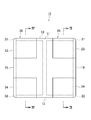
- FIG. 2 is a plan view of the capacitor array 10.
- 3 is a longitudinal sectional view taken along line III-III in FIG. 2
- FIG. 4 is a longitudinal sectional view taken along line IV-IV in FIG.
- the capacitor array 10 includes a rectangular parallelepiped ceramic sintered body 11 and two multilayer ceramic capacitor elements 20 and 30 (corresponding to the capacitor elements described in claims) disposed in the ceramic sintered body 11. I have.
- the ceramic sintered body 11 is made of, for example, a dielectric ceramic whose main component is BaTiO 3 , CaTiO 3 , SrTiO 3 , CaZrO 3 or the like.
- the two multilayer ceramic capacitor elements 20 and 30 are formed so as to have different values of equivalent series resistance (ESR). Specifically, the multilayer ceramic capacitor element 20 is set to have a higher ESR value than the multilayer ceramic capacitor element 30.
- ESR value of the multilayer ceramic capacitor element 20 (hereinafter referred to as “high ESR capacitor element 20”) is set higher than 100 m ⁇ , for example, about 200 to 700 m ⁇ .
- ESR value of the multilayer ceramic capacitor element 30 (hereinafter referred to as “low ESR capacitor element 30”) is set to 100 m ⁇ or less.
- the high ESR capacitor element 20 has a plurality of internal electrodes 21 and 22 stacked in the thickness direction through ceramic layers.
- the internal electrodes 21 and the internal electrodes 22 are formed in a substantially rectangular thin film shape, and are alternately stacked so as to face each other with a ceramic layer interposed therebetween.
- a pair of external electrodes 23 and 24 are disposed on the side surfaces 12 and 13 of the ceramic sintered body 11, and the internal electrode 21 is drawn out to one side surface 12 of the ceramic sintered body 11 and is externally provided. It is connected to the electrode 23.
- the internal electrode 22 is drawn out to the other side surface 13 of the ceramic sintered body 11 and connected to the external electrode 24.
- the pair of external electrodes 23 and external electrodes 24 are formed on the side surfaces 12 and 13 of the ceramic sintered body 11 so as to face each other with the ceramic sintered body 11 interposed therebetween. Since the external electrode 23 and the external electrode 24 have the same configuration, the external electrode 23 will be mainly described here.
- the external electrode 23 (24) includes a base electrode 23a (24a) connected to the internal electrode 21 (22), a resistance film 23b (24b) formed so as to cover the base electrode 23a (24a), and the resistance A nickel plating layer 23c (24c) and a tin plating layer 23d (24d) are formed so as to cover the film 23b (24b).
- the resistance film 23b (24b) is formed by baking a resistance paste containing a resistance component.
- a resistance component enters in series with respect to the capacity of the high ESR capacitor element 20, and the ESR of the high ESR capacitor element 20 increases.
- the base electrode 23a (24a), the resistance film 23b (24b), the nickel plating layer 23c (24c), and the tin plating layer 23d (24d) constituting the external electrode 23 (24) are respectively formed from the side surface 12 (13). It is formed so as to wrap around the side surface 14 orthogonal to the side surface 12 (13) and the upper and lower main surfaces.
- the low ESR capacitor element 30 has a plurality of internal electrodes 31 and 32 laminated in the thickness direction via ceramic layers.
- the internal electrodes 31 and the internal electrodes 32 are formed in a substantially rectangular thin film shape, and are alternately stacked so as to face each other through the ceramic layer.
- a pair of external electrodes 33, 34 are disposed on the side surfaces 12, 13 of the ceramic sintered body 11, and the internal electrode 31 is drawn out to one side surface 12 of the ceramic sintered body 11, The electrode 33 is connected.
- the internal electrode 32 is drawn out to the other side surface 13 of the ceramic sintered body 11 and connected to the external electrode 34.
- the pair of external electrodes 33 and external electrodes 34 are formed on the side surfaces 12 and 13 of the ceramic sintered body 11 so as to face each other with the ceramic sintered body 11 interposed therebetween. Since the external electrode 33 and the external electrode 34 have the same configuration, the external electrode 33 will be mainly described here.
- the external electrode 33 (34) includes a base electrode 33a (34a) connected to the internal electrode 31 (32), a nickel plating layer 33c (34c) and a tin plating layer formed so as to cover the base electrode 33a (34a). 33d (34d). That is, the external electrode 33 (34) is different from the external electrode 23 (24) described above in that it does not have the resistance film 23b (24b). Therefore, the ESR value of the low ESR capacitor element 30 is smaller than the ESR value of the high ESR capacitor element 20.
- the base electrode 33a (34a), the nickel plating layer 33c (34c), and the tin plating layer 33d (34d) constituting the external electrode 33 (34) are respectively connected to the side surface 12 (13) and the side surface 12 (13). It is formed so as to wrap around the orthogonal side surface 15 and the upper and lower main surfaces.
- FIG. 5 is a flowchart showing the procedure of the method for selecting the capacitor array 10.
- the sorting method includes a contact step S100, a connection step S110, a measurement step S120, and a sorting step S130.
- each step will be described in detail.
- a wiring 62 is connected to the measurement terminal 60, and a wiring 63 is connected to the measurement terminal 61.
- the pair of measurement terminals 60 and 61 are connected to the measuring instrument 50 through these two wires 62 and 63.
- an impedance analyzer or a network analyzer is used as the measuring instrument 50.
- connection step S110 the capacitor 70 is connected in parallel with the capacitor array 10 (each of the high ESR capacitor element 20 and the low ESR capacitor element 30) (that is, between the pair of measurement terminals 60 and 61).
- the connection step S110 or the contact step S100 described above may be executed first.
- a capacitor 70 is attached in advance between the pair of measurement terminals 60 and 61, and the measurement terminals 60 and 61 to which the capacitor 70 is attached are connected to the external electrodes 23 and 33 and the external electrodes 24 and 34 of the capacitor array 10. You may make it hit.
- FIG. 6 shows the impedance when a capacitor having a capacitance of 10 pF to 10 nF is connected in parallel with a 1005 size multilayer ceramic capacitor having a capacitance of 0.1 ⁇ F and an ESL of 450 pH.
- the capacitance of the capacitors connected in parallel was 60 pF or more, anti-resonance was observed in a frequency region of 1 GHz or less used for general characteristic selection. Therefore, in order to select the characteristics of the capacitor array 10 having various sizes and capacities, it is preferable that the capacitors 70 connected in parallel have a capacity of 100 pF to 10 nF. However, when impedance is measured at a frequency higher than 1 GHz, a capacitor 70 having a smaller capacity can be used.
- the capacitor array 10 is selected based on the impedance (minimum value) at the resonance frequency and the impedance (maximum value) at the anti-resonance frequency measured in the measurement step S120.
- the capacitor array 10 includes the high ESR capacitor element 20 and the low ESR capacitor element 30, the AC signal applied between the measurement terminals 60 and 61 has a frequency other than the vicinity of the anti-resonance frequency (resonance frequency).
- the low ESR capacitor element 30 and the high ESR capacitor element 20 at frequencies near the anti-resonance frequency. Therefore, the impedance at the anti-resonance frequency is reduced while the impedance at the resonance frequency is kept low.
- the capacitor array is composed of only the low ESR capacitor element 30, the impedance at the anti-resonance frequency becomes larger. Further, when the capacitor array is composed of only the high ESR capacitor element 20, the impedance near the resonance frequency becomes larger. Therefore, in the selection step S130, the capacitor array 10 is selected using such a difference in impedance characteristics.
- the measured impedance at the resonance frequency is equal to or lower than the first threshold value (for example, 20 m ⁇ ), and the impedance at the anti-resonance frequency is equal to the second threshold value (for example, 4 ⁇ ).
- the capacitor array 10 includes the high ESR capacitor element 20 having a large ESR in addition to the low ESR capacitor element 30 according to the standard, and the capacitor array 10 is a non-defective product. To be judged.
- the capacitor array 10 is Judged as defective.
- the processing in the selection step S130 can be performed using, for example, a computer or the like that is communicably connected to the measuring device 50 through GPIB, USB, or LAN.
- the capacitor array 10 includes a high ESR capacitor element 20 having a capacitance of 0.1 ⁇ F, ESL of 450 pH, and ESR of 200 m ⁇ , and a low ESR capacitor element 30 having a capacitance of 0.1 ⁇ F, ESL of 450 pH, and ESR of 10 m ⁇ . What was included was used.
- the impedance frequency characteristics were also measured.
- Impedance frequency characteristics when a capacitor 70 of 500 pF is connected in parallel to each of the capacitor array 10 according to the embodiment, the capacitor array consisting only of the low ESR capacitor 30 and the capacitor array consisting only of the high ESR capacitor 20 (measurement result) Is shown in FIG.
- the horizontal axis of the graph shown in FIG. 7 is frequency (Hz), and the vertical axis is impedance ( ⁇ ).
- the measurement result of the capacitor array 10 is indicated by a solid line
- the measurement result of the capacitor array including only the low ESR capacitor 30 is indicated by a broken line
- the measurement result of the capacitor array including only the high ESR capacitor 20 is indicated by an alternate long and short dash line. Shown respectively.
- the impedance at the anti-resonance frequency is relatively low and is suppressed to about 2.5 ⁇ .
- the impedance increases and exceeds 100 m ⁇ .
- the impedance at the resonance frequency is relatively low and is suppressed to 20 m ⁇ or less.
- the impedance at the anti-resonance frequency is relatively low and is suppressed to 4 ⁇ or less. Therefore, in this case, by setting the first threshold value at the resonance frequency (25 MHz) to 20 m ⁇ and setting the second threshold value at the anti-resonance frequency (470 MHz) to 4 ⁇ , the low ESR capacitor 30 Only the capacitor array 10 including the high ESR capacitor 20 can be determined as a non-defective product.
- a capacitor array consisting only of the low ESR capacitor 30 and a capacitor array consisting only of the high ESR capacitor 20 can be determined to be defective and selectively removed.
- the capacitor 70 is connected in parallel with the capacitor array 10 (that is, between the pair of measurement terminals 60 and 61). Therefore, when the impedance is measured by changing the frequency of the AC signal to be applied, the resonance due to the capacitance of the capacitor array 10 and the ESL, and the anti-resonance due to the capacitance of the capacitor 70 connected in parallel and the ESL of the capacitor array 10 are obtained. Occurs.
- the capacitor array 10 includes the high ESR capacitor element 20 and the low ESR capacitor element 30, the AC signal applied between the measurement terminals 60 and 61 has a frequency other than the vicinity of the antiresonance frequency (resonance frequency).
- the low ESR capacitor element 30 and the high ESR capacitor element 20 at frequencies near the anti-resonance frequency.
- the impedance at the anti-resonance frequency is reduced while the impedance at the resonance frequency is kept low.
- the capacitor array 10 includes only the low ESR capacitor element 30, the impedance at the anti-resonance frequency becomes larger.
- the capacitor array 10 is composed of only the high ESR capacitor element 20, the impedance near the resonance frequency becomes larger. Therefore, by measuring the impedance by changing the frequency of the applied AC signal, the capacitor array 10 includes the high ESR capacitor element 20 having a large ESR in addition to the low ESR capacitor element 30 in accordance with the standard. It can be determined whether or not. Therefore, it is possible to select the capacitor array 10 including a plurality (two in this embodiment) of capacitor elements 20 and 30 having different ESR.
- the impedance at the resonance frequency and the impedance at the anti-resonance frequency are measured.
- the capacitor array 10 includes the high ESR capacitor element 20 and the low ESR capacitor element 30, the impedance at the anti-resonance frequency is reduced while the impedance at the resonance frequency is kept low. Is done. Therefore, when the impedance at the resonance frequency is equal to or lower than the first threshold value and the impedance at the anti-resonance frequency is equal to or lower than the second threshold value, the low ESR capacitor element 30 is included in the capacitor array 10.
- the high ESR capacitor element 20 having a large ESR is included according to the standard (that is, a non-defective product).
- the capacitor array 10 including a plurality (two in this embodiment) of capacitor elements 20 and 30 having different ESRs is selected. can do. Therefore, the capacitor array 10 can be selected in a shorter time.
- the present invention is not limited to the above-described embodiments, and various modifications can be made.
- the four-terminal capacitor array 10 including the two capacitor elements 20 and 30 has been described as an example.
- the number of capacitor elements included in the capacitor array is not limited to two.
- the capacitor array may include three capacitor elements (6 terminals), four capacitor elements (8 terminals), or a larger number of capacitor elements.
- the impedance at the resonance frequency and the impedance at the anti-resonance frequency are measured, the impedance at the resonance frequency is less than or equal to the first threshold value, and the impedance at the anti-resonance frequency is second.
- the threshold value or less the capacitor array 10 was determined to be a good product.
- the impedance is measured by changing the frequency, and in the selection step S130, the minimum value of the measured impedance is not more than the first threshold value, and the impedance When the maximum value is equal to or less than the second threshold value, the capacitor array 10 may be determined as a non-defective product.
- the capacitor 70 when the capacitor 70 is connected in parallel with the capacitor array 10 and the impedance is measured by changing the frequency of the AC signal to be applied, resonance and anti-resonance occur.
- the capacitor array 10 when the capacitor array 10 includes the high ESR capacitor element 20 and the low ESR capacitor element 30, the impedance at the anti-resonance frequency is reduced while the impedance at the resonance frequency is kept low. Is done.
- the capacitor array 10 when the capacitor array 10 includes only the low ESR capacitor element 30, the impedance at the anti-resonance frequency becomes larger.
- the capacitor array is composed of only the high ESR capacitor element 20, the impedance near the resonance frequency becomes larger.
- the impedance is minimum at the resonance frequency and maximum at the anti-resonance frequency.
- the capacitor array when the minimum impedance value is less than the first threshold value and the maximum value is less than the second threshold value, the capacitor array has a large ESR in addition to the low ESR capacitor element.
- the high ESR capacitor element 20 is included according to the standard (that is, a non-defective product). Therefore, according to this configuration, the capacitor array 10 including a plurality (two in this embodiment) of capacitor elements 20 and 30 having different ESRs can be selected based on the measured minimum and maximum values of impedance. It becomes possible.
- the capacitor array 10 when the impedance at the resonance frequency is equal to or lower than the first threshold value (for example, 20 m ⁇ ) and the impedance at the anti-resonance frequency is equal to or lower than the second threshold value (for example, 4 ⁇ ), the capacitor The array 10 was judged as a good product.
- the impedance at the resonance frequency is greater than or equal to the third threshold value (eg, 10 m ⁇ in the example of FIG. 7), and the impedance at the antiresonance frequency is greater than or equal to the fourth threshold value (eg, 3 ⁇ ).
- the capacitor array 10 may be determined as a good product.
- the impedance at the resonance frequency is within a predetermined range (in the example of FIG. 7, for example, 10 m ⁇ to 20 m ⁇ ), and the impedance at the anti-resonance frequency is within the predetermined range (for example, 3 ⁇ to 4 ⁇ ). In this case, the capacitor array 10 may be determined as a good product.
Abstract
Provided is a capacitor array screening method with which it is possible to screen capacitor arrays that include a plurality of capacitor elements having different equivalent series resistances. This screening method involves: a contact step of bringing a pair of measurement terminals (60, 61) into contact with external electrodes (23, 33) provided on one side surface (12) of a capacitor array (10) and external electrodes (24, 34) provided on another side surface (13) thereof; a connection step of connecting the capacitor array (10) in parallel to a capacitor (70); a measurement step of applying an alternating-current signal between the pair of measurement terminals (60, 61) and measuring the impedance at the resonant frequency of the capacitor array (10), which is connected in parallel to the capacitor (70), and the impedance at the anti-resonant frequency thereof; and a screening step of determining that the capacitor array (10) is non-defective if the impedance at the resonant frequency is lower than or equal to a first threshold and the impedance at the anti-resonant frequency is lower than or equal to a second threshold.
Description
本発明は、1つの誘電体素体内に複数のコンデンサ素子が配設されたコンデンサアレイの選別方法に関する。
The present invention relates to a method for selecting a capacitor array in which a plurality of capacitor elements are arranged in one dielectric element.
従来から、積層セラミックコンデンサの信頼性を向上させるために、例えば積層誘電体内部の構造欠陥などを有する積層セラミックコンデンサを選別除去するスクリーニングが行われている。ここで、下記特許文献1には、初期の内部構造欠陥や使用期間中に寿命劣化を来すおそれのある欠陥を有する積層セラミックコンデンサを選別除去するスクリーニング方法が開示されている。このスクリーニング方法では、積層セラミックコンデンサが125℃以上180℃以下の温度環境下に置かれた状態で、端子電極間に直流電圧が印加され、直流絶縁抵抗が測定される。直流電圧が印加されるステップは、2つのステップを含んでおり、第1のステップでは20~40(V/μm)の直流電圧が印加され、第2のステップでは、定格電圧を考慮した直流電圧が印加される。このスクリーニング方法によれば、電歪クラックを発生させず、かつ端子電極にダメージを与えることなく積層セラミックコンデンサの選別を行うことができる。
Conventionally, in order to improve the reliability of a multilayer ceramic capacitor, for example, screening for selectively removing a multilayer ceramic capacitor having a structural defect inside the multilayer dielectric has been performed. Here, Patent Document 1 below discloses a screening method for selectively removing a multilayer ceramic capacitor having an initial internal structural defect or a defect that may cause a life deterioration during a period of use. In this screening method, a DC voltage is applied between the terminal electrodes in a state where the multilayer ceramic capacitor is placed in a temperature environment of 125 ° C. or higher and 180 ° C. or lower, and the DC insulation resistance is measured. The step of applying the DC voltage includes two steps. In the first step, a DC voltage of 20 to 40 (V / μm) is applied, and in the second step, the DC voltage considering the rated voltage is applied. Is applied. According to this screening method, it is possible to select a multilayer ceramic capacitor without causing electrostrictive cracks and without damaging the terminal electrodes.
ところで、特許文献2には、小容量積層セラミックコンデンサ素子と、等価直列抵抗が大きな大容量積層セラミックコンデンサ素子とを組み合わせた複合積層セラミックコンデンサが開示されている。この複合積層セラミックコンデンサは、大容量積層セラミックコンデンサ素子の外部電極の等価直列抵抗の抵抗値を、小容量積層セラミックコンデンサ素子における外部電極の等価直列抵抗の抵抗値よりも大きくするとともに、大容量積層セラミックコンデンサ素子と小容量積層セラミックコンデンサ素子とを所定の間隔以上の隙間部を設けて結合したものである。
Incidentally, Patent Document 2 discloses a composite multilayer ceramic capacitor in which a small-capacity multilayer ceramic capacitor element and a large-capacity multilayer ceramic capacitor element having a large equivalent series resistance are combined. This composite multilayer ceramic capacitor has a resistance value of an equivalent series resistance of an external electrode of a large-capacity multilayer ceramic capacitor element larger than a resistance value of an equivalent series resistance of an external electrode in a small-capacity multilayer ceramic capacitor element. A ceramic capacitor element and a small-capacity multilayer ceramic capacitor element are combined with a gap of a predetermined distance or more.
ここで、特許文献2に記載されているような複合積層セラミックコンデンサを選別しようとした場合、上述した特許文献1記載のスクリーニング方法では、大容量積層セラミックコンデンサ素子の等価直列抵抗が、小容量積層セラミックコンデンサ素子の等価直列抵抗よりも大きいか否かを判定することができない。すなわち、複合積層セラミックコンデンサ内に、大きな等価直列抵抗を持った積層セラミックコンデンサ素子が規格通りに含まれているか否かを判別して、複合積層セラミックコンデンサを選別することができない。
Here, when trying to select a composite multilayer ceramic capacitor as described in Patent Document 2, in the above-described screening method described in Patent Document 1, the equivalent series resistance of the large-capacity multilayer ceramic capacitor element is small. It cannot be determined whether or not it is larger than the equivalent series resistance of the ceramic capacitor element. That is, the composite multilayer ceramic capacitor cannot be selected by determining whether or not the multilayer ceramic capacitor element having a large equivalent series resistance is included in the composite multilayer ceramic capacitor according to the standard.
本発明は、上記問題点を解消する為になされたものであり、等価直列抵抗が異なる複数のコンデンサ素子を含むコンデンサアレイを選別することが可能なコンデンサアレイの選別方法を提供することを目的とする。
The present invention has been made to solve the above-described problems, and an object thereof is to provide a capacitor array selection method capable of selecting a capacitor array including a plurality of capacitor elements having different equivalent series resistances. To do.
本発明に係るコンデンサアレイの選別方法は、複数のコンデンサ素子を含むコンデンサアレイの選別方法であって、コンデンサ素子の配列方向に沿って、コンデンサアレイの第1の側面に設けられた複数の外部電極、及び、該第1の側面と対向する第2の側面に設けられた複数の外部電極に対して、導電性を有する一対の測定端子を当接する当接ステップと、コンデンサアレイと並列にコンデンサを接続する接続ステップと、一対の測定端子間に交流信号を印加するとともに、該交流信号の周波数を変えて、コンデンサが並列に接続されたコンデンサアレイのインピーダンスを測定する測定ステップと、測定ステップで測定されたインピーダンスに基づいて、コンデンサアレイを選別する選別ステップとを備えることを特徴とする。
The capacitor array sorting method according to the present invention is a capacitor array sorting method including a plurality of capacitor elements, and a plurality of external electrodes provided on the first side surface of the capacitor array along the arrangement direction of the capacitor elements. A contact step of contacting a pair of conductive measuring terminals with a plurality of external electrodes provided on the second side surface opposite to the first side surface, and a capacitor in parallel with the capacitor array. A connection step to connect, a measurement step to apply an AC signal between a pair of measurement terminals, change the frequency of the AC signal, and measure the impedance of a capacitor array in which capacitors are connected in parallel, and a measurement step to measure And a sorting step for sorting the capacitor array based on the impedance obtained.
本発明に係るコンデンサアレイの選別方法によれば、コンデンサアレイ(コンデンサアレイを構成する複数のコンデンサ素子それぞれ)と並列に(すなわち一対の測定端子間に)コンデンサが接続される。そのため、印加する交流信号の周波数を変化させてインピーダンスを測定すると、コンデンサアレイ自身が持つ容量(ESC:Equivalent Series Capacitance)とESL(Equivalent Series Inductance:等価直列インダクタンス)とによる共振、及び、並列に接続されたコンデンサの容量とコンデンサアレイのESLとによる反共振(並列共振)が生じる。ここで、例えば、コンデンサアレイが、等価直列抵抗(ESR:Equivalent Series Resistance)の値が異なる複数のコンデンサ素子を含んでいる場合、測定端子間に印加された交流信号は、反共振周波数の付近以外の周波数(共振周波数を含む)ではESRの値が小さい方のコンデンサ素子(以下「低ESRコンデンサ素子」ともいう)を通り、反共振周波数の付近の周波数ではESRの値が高い方のコンデンサ素子(以下「高ESRコンデンサ素子」ともいう)を通る。そのため、共振周波数でのインピーダンスが低く保たれたまま、反共振周波数でのインピーダンスが低減される。これに対して、コンデンサアレイが低ESRコンデンサ素子のみで構成されている場合には、反共振周波数でのインピーダンスがより大きくなる。また、コンデンサアレイが高ESRコンデンサ素子のみで構成されているときには、共振周波数付近でのインピーダンスがより大きくなる。そのため、印加する交流信号の周波数を変えてインピーダンスを測定することにより、コンデンサアレイ内に、低ESRコンデンサ素子に加えて、大きな等価直列抵抗を持った高ESRコンデンサ素子が規格通りに含まれているか否かを判別することができる。よって、等価直列抵抗が異なる複数のコンデンサ素子を含むコンデンサアレイを選別することが可能となる。
According to the method for selecting a capacitor array according to the present invention, a capacitor is connected in parallel (that is, between a pair of measurement terminals) in parallel with the capacitor array (each of a plurality of capacitor elements constituting the capacitor array). Therefore, when the impedance is measured by changing the frequency of the AC signal to be applied, the capacitance (ESC: Equivalent Series Capacitance) and ESL (Equivalent Series Inductance) of the capacitor array itself are connected in parallel. Anti-resonance (parallel resonance) occurs due to the capacitance of the capacitor and the ESL of the capacitor array. Here, for example, when the capacitor array includes a plurality of capacitor elements having different values of equivalent series resistance (ESR: Equivalent Series Resistance), the AC signal applied between the measurement terminals is not in the vicinity of the anti-resonance frequency. At the frequency (including the resonance frequency), the capacitor element with the smaller ESR value (hereinafter also referred to as “low ESR capacitor element”) and the capacitor element with the higher ESR value at the frequency near the anti-resonance frequency ( Hereinafter referred to as “high ESR capacitor element”). Therefore, the impedance at the anti-resonance frequency is reduced while the impedance at the resonance frequency is kept low. On the other hand, when the capacitor array is composed of only low ESR capacitor elements, the impedance at the anti-resonance frequency becomes larger. Further, when the capacitor array is composed of only high ESR capacitor elements, the impedance near the resonance frequency becomes larger. Therefore, by measuring the impedance by changing the frequency of the AC signal to be applied, in addition to the low ESR capacitor element, the high ESR capacitor element having a large equivalent series resistance is included in the capacitor array as specified. It can be determined whether or not. Therefore, it is possible to select a capacitor array including a plurality of capacitor elements having different equivalent series resistances.
本発明に係るコンデンサアレイの選別方法では、選別ステップにおいて、測定ステップで測定されたインピーダンスの最小値が第1しきい値以下であり、かつ、該インピーダンスの最大値が第2しきい値以下の場合に、コンデンサアレイを良品と判断することが好ましい。
In the capacitor array sorting method according to the present invention, in the sorting step, the minimum impedance value measured in the measurement step is less than or equal to the first threshold value, and the maximum impedance value is less than or equal to the second threshold value. In this case, it is preferable to judge the capacitor array as a good product.
上述したように、本発明に係るコンデンサアレイの選別方法によれば、コンデンサアレイと並列にコンデンサが接続されため、印加する交流信号の周波数を変化させてインピーダンスを測定すると、共振及び反共振が生じる。また、上述したように、例えば、コンデンサアレイを構成する複数のコンデンサ素子が、等価直列抵抗の値が異なる複数のコンデンサ素子を含んでいる場合、共振周波数でのインピーダンスが低く保たれたまま、反共振周波数でのインピーダンスが低減される。これに対して、コンデンサアレイが低ESRコンデンサ素子のみで構成されている場合には、反共振周波数でのインピーダンスがより大きくなる。また、コンデンサアレイが高ESRコンデンサ素子のみで構成されているときには、共振周波数付近でのインピーダンスがより大きくなる。ここで、インピーダンスは、共振周波数で最小となり、反共振周波数で最大となる。よって、インピーダンスの最小値が第1しきい値以下であり、かつ、最大値が第2しきい値以下である場合には、コンデンサアレイ内に、低ESRコンデンサ素子に加えて、大きな等価直列抵抗を持った高ESRコンデンサ素子が規格通りに含まれている(すなわち良品)と判断することができる。従って、このようにすれば、測定されたインピーダンスの最小値及び最大値に基づいて、等価直列抵抗が異なる複数のコンデンサ素子を含むコンデンサアレイを適切に選別することが可能となる。
As described above, according to the method for selecting a capacitor array according to the present invention, a capacitor is connected in parallel with the capacitor array. Therefore, when the impedance is measured by changing the frequency of the applied AC signal, resonance and anti-resonance occur. . As described above, for example, when a plurality of capacitor elements constituting the capacitor array include a plurality of capacitor elements having different values of equivalent series resistance, the impedance at the resonance frequency is kept low, Impedance at the resonant frequency is reduced. On the other hand, when the capacitor array is composed of only low ESR capacitor elements, the impedance at the anti-resonance frequency becomes larger. Further, when the capacitor array is composed of only high ESR capacitor elements, the impedance near the resonance frequency becomes larger. Here, the impedance is minimum at the resonance frequency and maximum at the anti-resonance frequency. Therefore, in the case where the minimum impedance value is equal to or lower than the first threshold value and the maximum value is equal to or lower than the second threshold value, a large equivalent series resistance is added to the capacitor array in addition to the low ESR capacitor element. It can be determined that a high-ESR capacitor element having an A is included according to the standard (that is, a non-defective product). Accordingly, in this way, a capacitor array including a plurality of capacitor elements having different equivalent series resistances can be appropriately selected based on the measured minimum and maximum impedance values.
本発明に係るコンデンサアレイの選別方法では、測定ステップにおいて、共振周波数でのインピーダンス、及び、反共振周波数でのインピーダンスを測定し、選別ステップにおいて、測定ステップで測定された共振周波数でのインピーダンスが第1しきい値以下であり、かつ、反共振周波数でのインピーダンスが第2しきい値以下の場合に、前記コンデンサアレイを良品と判断することが好ましい。
In the capacitor array sorting method according to the present invention, the impedance at the resonance frequency and the impedance at the anti-resonance frequency are measured in the measurement step, and the impedance at the resonance frequency measured in the measurement step is measured in the selection step. It is preferable that the capacitor array is determined to be a non-defective product when the threshold value is 1 threshold value or less and the impedance at the antiresonance frequency is 2nd threshold value or less.
この場合、共振周波数でのインピーダンス、及び反共振周波数でのインピーダンスが測定される。ここで、上述したように、例えば、コンデンサアレイを構成する複数のコンデンサ素子が、等価直列抵抗の値が異なる複数のコンデンサ素子を含んでいる場合、共振周波数でのインピーダンスが低く保たれたまま、反共振周波数でのインピーダンスが低減される。よって、共振周波数でのインピーダンスが第1しきい値以下であり、かつ、反共振周波数でのインピーダンスが第2しきい値以下である場合には、コンデンサアレイ内に、低ESRコンデンサ素子に加えて、大きな等価直列抵抗を持った高ESRコンデンサ素子が規格通りに含まれている(すなわち良品)と判断することができる。従って、この場合、2つの周波数(共振周波数、反共振周波数)でのインピーダンスを測定することにより、等価直列抵抗が異なる複数のコンデンサ素子を含むコンデンサアレイを選別することができる。よって、より短時間でコンデンサアレイの選別が可能となる。
In this case, the impedance at the resonance frequency and the impedance at the anti-resonance frequency are measured. Here, as described above, for example, when the plurality of capacitor elements constituting the capacitor array include a plurality of capacitor elements having different values of equivalent series resistance, the impedance at the resonance frequency is kept low. Impedance at the anti-resonance frequency is reduced. Therefore, when the impedance at the resonance frequency is equal to or lower than the first threshold value and the impedance at the anti-resonance frequency is equal to or lower than the second threshold value, in addition to the low ESR capacitor element in the capacitor array Therefore, it can be determined that a high ESR capacitor element having a large equivalent series resistance is included according to the standard (that is, a non-defective product). Therefore, in this case, a capacitor array including a plurality of capacitor elements having different equivalent series resistances can be selected by measuring impedances at two frequencies (resonance frequency and anti-resonance frequency). Therefore, the capacitor array can be selected in a shorter time.
本発明に係るコンデンサアレイの選別方法では、上記複数のコンデンサ素子が、等価直列抵抗の値が異なる2個以上のコンデンサ素子を含むことが好ましい。
In the method for selecting a capacitor array according to the present invention, it is preferable that the plurality of capacitor elements include two or more capacitor elements having different equivalent series resistance values.
上述したように、本発明に係るコンデンサアレイの選別方法によれば、コンデンサアレイ内に、低ESRコンデンサ素子と高ESRコンデンサ素子とが規格通りに含まれているか否かを判別することができる。よって、等価直列抵抗の値が異なる2個以上のコンデンサ素子を含むコンデンサアレイを適切に選別することができる。
As described above, according to the method for selecting a capacitor array according to the present invention, it is possible to determine whether or not a low ESR capacitor element and a high ESR capacitor element are included in the capacitor array according to the standard. Accordingly, it is possible to appropriately select a capacitor array including two or more capacitor elements having different equivalent series resistance values.
本発明によれば、等価直列抵抗が異なる複数のコンデンサ素子を含むコンデンサアレイを選別することが可能となる。
According to the present invention, it is possible to select a capacitor array including a plurality of capacitor elements having different equivalent series resistances.
以下、図面を参照して本発明の好適な実施形態について詳細に説明する。なお、各図において、同一要素には同一符号を付して重複する説明を省略する。
Hereinafter, preferred embodiments of the present invention will be described in detail with reference to the drawings. In addition, in each figure, the same code | symbol is attached | subjected to the same element and the overlapping description is abbreviate | omitted.
図1は、実施形態に係るコンデンサアレイの選別方法を実施する装置の一例を示す模式図である。本実施形態に係るコンデンサアレイの選別方法(以下、単に「選別方法」ともいう)は、等価直列抵抗(ESR)が異なる複数の積層セラミックコンデンサ素子(以下、単に「コンデンサ素子」という)を含むチップ型積層セラミックコンデンサアレイ(以下、単に「コンデンサアレイ」という)を選別する方法である。本選別方法は、例えば、ESRが異なる2つのコンデンサ素子20,30を含むコンデンサアレイ10の外部電極23,33と外部電極24,34とに、間にコンデンサ70が取り付けられた一対の金属製の測定端子60,61を当接した後、測定器50から交流信号を印加してインピーダンスを測定し、その測定結果に基づいて、ESRが異なるコンデンサ素子20,30が規格通りに含まれているか(又は形成されているか)否かを判断して、不良品を選別除去する手法である。
FIG. 1 is a schematic diagram illustrating an example of an apparatus for performing a capacitor array sorting method according to an embodiment. The capacitor array sorting method according to the present embodiment (hereinafter also simply referred to as “sorting method”) includes a plurality of multilayer ceramic capacitor elements (hereinafter simply referred to as “capacitor elements”) having different equivalent series resistances (ESR). This is a method of selecting a type multilayer ceramic capacitor array (hereinafter simply referred to as “capacitor array”). This selection method is, for example, a pair of metal made by attaching a capacitor 70 between the external electrodes 23 and 33 and the external electrodes 24 and 34 of the capacitor array 10 including two capacitor elements 20 and 30 having different ESR. After contacting the measurement terminals 60 and 61, an AC signal is applied from the measuring device 50 to measure the impedance, and based on the measurement result, whether the capacitor elements 20 and 30 having different ESR are included in accordance with the standard ( In other words, it is a method of selecting and removing defective products by determining whether or not they are formed.
選別方法の詳細については後述することとし、まず始めに、図2~4を併せて用いて、選別の対象であるのコンデンサアレイ10について説明する。図2は、コンデンサアレイ10の平面図である。また、図3は、図2のIII-III線に沿った縦断面図であり、図4は、図2のIV-IV線に沿った縦断面図である。
The details of the sorting method will be described later. First, the capacitor array 10 that is the object of sorting will be described with reference to FIGS. FIG. 2 is a plan view of the capacitor array 10. 3 is a longitudinal sectional view taken along line III-III in FIG. 2, and FIG. 4 is a longitudinal sectional view taken along line IV-IV in FIG.
コンデンサアレイ10は、直方体形状のセラミック焼結体11と、該セラミック焼結体11内に配設された2個の積層セラミックコンデンサ素子20,30(請求の範囲に記載のコンデンサ素子に相当)を備えている。セラミック焼結体11は、例えば、BaTiO3、CaTiO3、SrTiO3、CaZrO3などを主成分とする誘電体セラミックから形成されている。
The capacitor array 10 includes a rectangular parallelepiped ceramic sintered body 11 and two multilayer ceramic capacitor elements 20 and 30 (corresponding to the capacitor elements described in claims) disposed in the ceramic sintered body 11. I have. The ceramic sintered body 11 is made of, for example, a dielectric ceramic whose main component is BaTiO 3 , CaTiO 3 , SrTiO 3 , CaZrO 3 or the like.
2個の積層セラミックコンデンサ素子20,30は、互いに等価直列抵抗(ESR)の値が異なるように形成されている。具体的には、積層セラミックコンデンサ素子20は、積層セラミックコンデンサ素子30よりもESR値が高く設定されている。ここで、積層セラミックコンデンサ素子20(以下「高ESRコンデンサ素子20」という)のESR値は、100mΩよりも高く、例えば、200~700mΩ程度に設定される。一方、積層セラミックコンデンサ素子30(以下「低ESRコンデンサ素子30」という)のESR値は、100mΩ以下に設定される。
The two multilayer ceramic capacitor elements 20 and 30 are formed so as to have different values of equivalent series resistance (ESR). Specifically, the multilayer ceramic capacitor element 20 is set to have a higher ESR value than the multilayer ceramic capacitor element 30. Here, the ESR value of the multilayer ceramic capacitor element 20 (hereinafter referred to as “high ESR capacitor element 20”) is set higher than 100 mΩ, for example, about 200 to 700 mΩ. On the other hand, the ESR value of the multilayer ceramic capacitor element 30 (hereinafter referred to as “low ESR capacitor element 30”) is set to 100 mΩ or less.
図2,3に示されるように、高ESRコンデンサ素子20は、セラミック層を介して厚み方向に積層された複数の内部電極21,22を有している。内部電極21及び内部電極22は、略矩形の薄膜状に形成されており、セラミック層を介して互いに対向するように、交互に積層されている。ここで、セラミック焼結体11の側面12,13には、一対の外部電極23,24が配設されており、内部電極21は、セラミック焼結体11の一方の側面12に引き出され、外部電極23と接続されている。内部電極22は、セラミック焼結体11の他方の側面13に引き出され、外部電極24と接続されている。
As shown in FIGS. 2 and 3, the high ESR capacitor element 20 has a plurality of internal electrodes 21 and 22 stacked in the thickness direction through ceramic layers. The internal electrodes 21 and the internal electrodes 22 are formed in a substantially rectangular thin film shape, and are alternately stacked so as to face each other with a ceramic layer interposed therebetween. Here, a pair of external electrodes 23 and 24 are disposed on the side surfaces 12 and 13 of the ceramic sintered body 11, and the internal electrode 21 is drawn out to one side surface 12 of the ceramic sintered body 11 and is externally provided. It is connected to the electrode 23. The internal electrode 22 is drawn out to the other side surface 13 of the ceramic sintered body 11 and connected to the external electrode 24.
一対の外部電極23と外部電極24とは、セラミック焼結体11を挟んで対向するように、該セラミック焼結体11の側面12,13に形成されている。なお、外部電極23及び外部電極24の構成は同一であるので、ここでは、外部電極23を主にして説明する。外部電極23(24)は、内部電極21(22)に接続される下地電極23a(24a)と、該下地電極23a(24a)を覆うように形成される抵抗皮膜23b(24b)と、該抵抗皮膜23b(24b)を覆うように形成されるニッケルメッキ層23c(24c)及びスズメッキ層23d(24d)と含んで構成されている。
The pair of external electrodes 23 and external electrodes 24 are formed on the side surfaces 12 and 13 of the ceramic sintered body 11 so as to face each other with the ceramic sintered body 11 interposed therebetween. Since the external electrode 23 and the external electrode 24 have the same configuration, the external electrode 23 will be mainly described here. The external electrode 23 (24) includes a base electrode 23a (24a) connected to the internal electrode 21 (22), a resistance film 23b (24b) formed so as to cover the base electrode 23a (24a), and the resistance A nickel plating layer 23c (24c) and a tin plating layer 23d (24d) are formed so as to cover the film 23b (24b).
ここで、抵抗皮膜23b(24b)は、抵抗成分を含有する抵抗ペーストを焼き付けることによって形成される。抵抗皮膜23b(24b)が形成されることにより高ESRコンデンサ素子20の容量に対して抵抗成分が直列に入ることとなり、高ESRコンデンサ素子20のESRが高くなる。なお、外部電極23(24)を構成する下地電極23a(24a)、抵抗皮膜23b(24b)、ニッケルメッキ層23c(24c)、及びスズメッキ層23d(24d)それぞれは、側面12(13)から、該側面12(13)と直交する側面14及び上下の主面に回り込むように形成されている。
Here, the resistance film 23b (24b) is formed by baking a resistance paste containing a resistance component. By forming the resistance film 23b (24b), a resistance component enters in series with respect to the capacity of the high ESR capacitor element 20, and the ESR of the high ESR capacitor element 20 increases. The base electrode 23a (24a), the resistance film 23b (24b), the nickel plating layer 23c (24c), and the tin plating layer 23d (24d) constituting the external electrode 23 (24) are respectively formed from the side surface 12 (13). It is formed so as to wrap around the side surface 14 orthogonal to the side surface 12 (13) and the upper and lower main surfaces.
一方、図2,4に示されるように、低ESRコンデンサ素子30は、セラミック層を介して厚み方向に積層された複数の内部電極31,32を有している。内部電極31及び内部電極32は、略矩形の薄膜状に形成されており、セラミック層を介して互いに対向するように、交互に積層されている。ここで、セラミック焼結体11の側面12,13には、一対の外部電極33,34が配設されており、内部電極31は、セラミック焼結体11の一方の側面12に引き出され、外部電極33と接続されている。内部電極32は、セラミック焼結体11の他方の側面13に引き出され、外部電極34と接続されている。
On the other hand, as shown in FIGS. 2 and 4, the low ESR capacitor element 30 has a plurality of internal electrodes 31 and 32 laminated in the thickness direction via ceramic layers. The internal electrodes 31 and the internal electrodes 32 are formed in a substantially rectangular thin film shape, and are alternately stacked so as to face each other through the ceramic layer. Here, a pair of external electrodes 33, 34 are disposed on the side surfaces 12, 13 of the ceramic sintered body 11, and the internal electrode 31 is drawn out to one side surface 12 of the ceramic sintered body 11, The electrode 33 is connected. The internal electrode 32 is drawn out to the other side surface 13 of the ceramic sintered body 11 and connected to the external electrode 34.
一対の外部電極33と外部電極34とは、セラミック焼結体11を挟んで対向するように、該セラミック焼結体11の側面12,13に形成されている。なお、外部電極33及び外部電極34の構成は同一であるので、ここでは、外部電極33を主にして説明する。外部電極33(34)は、内部電極31(32)に接続される下地電極33a(34a)と、該下地電極33a(34a)を覆うように形成されるニッケルメッキ層33c(34c)及びスズメッキ層33d(34d)と含んで構成されている。すなわち、外部電極33(34)は、上述した外部電極23(24)とは、抵抗皮膜23b(24b)を有しない点で異なっている。そのため、低ESRコンデンサ素子30のESR値は、高ESRコンデンサ素子20のESR値よりも小さくなる。
The pair of external electrodes 33 and external electrodes 34 are formed on the side surfaces 12 and 13 of the ceramic sintered body 11 so as to face each other with the ceramic sintered body 11 interposed therebetween. Since the external electrode 33 and the external electrode 34 have the same configuration, the external electrode 33 will be mainly described here. The external electrode 33 (34) includes a base electrode 33a (34a) connected to the internal electrode 31 (32), a nickel plating layer 33c (34c) and a tin plating layer formed so as to cover the base electrode 33a (34a). 33d (34d). That is, the external electrode 33 (34) is different from the external electrode 23 (24) described above in that it does not have the resistance film 23b (24b). Therefore, the ESR value of the low ESR capacitor element 30 is smaller than the ESR value of the high ESR capacitor element 20.
なお、外部電極33(34)を構成する下地電極33a(34a)、ニッケルメッキ層33c(34c)、及びスズメッキ層33d(34d)それぞれは、側面12(13)から、該側面12(13)と直交する側面15及び上下の主面に回り込むように形成されている。
The base electrode 33a (34a), the nickel plating layer 33c (34c), and the tin plating layer 33d (34d) constituting the external electrode 33 (34) are respectively connected to the side surface 12 (13) and the side surface 12 (13). It is formed so as to wrap around the orthogonal side surface 15 and the upper and lower main surfaces.
続いて、図1及び図5~7を併せて参照しつつ、コンデンサアレイ10の選別方法について説明する。図5は、コンデンサアレイ10の選別方法の手順を示すフローチャートである。図5に示されるように、本選別方法は、当接ステップS100、接続ステップS110、測定ステップS120、及び選別ステップS130からなっている。以下、各ステップについて詳細に説明する。
Subsequently, a method for selecting the capacitor array 10 will be described with reference to FIGS. 1 and 5 to 7 together. FIG. 5 is a flowchart showing the procedure of the method for selecting the capacitor array 10. As shown in FIG. 5, the sorting method includes a contact step S100, a connection step S110, a measurement step S120, and a sorting step S130. Hereinafter, each step will be described in detail.
(当接ステップ)
まず、当接ステップS100では、図1に示されるように、高ESRコンデンサ素子20と低ESRコンデンサ素子30の配列方向に沿ってコンデンサアレイ10の側面12(請求の範囲に記載の「第1の側面」に相当)に設けられた2つの外部電極23,33、及び、該側面12と対向する側面13(請求の範囲に記載の「第2の側面」に相当)に設けられた2つの外部電極24,34に対して、導電性を有する一対の測定端子60,61が当接される。それぞれの測定端子60,61は、例えば、金属製の矩形の板状部材である。 (Contact step)
First, in the contact step S100, as shown in FIG. 1, theside surface 12 of the capacitor array 10 along the arrangement direction of the high ESR capacitor element 20 and the low ESR capacitor element 30 ( Two external electrodes 23, 33 provided on the side surface) and two external electrodes provided on the side surface 13 (corresponding to the “second side surface” recited in the claims). A pair of conductive measuring terminals 60 and 61 are brought into contact with the electrodes 24 and 34. Each of the measurement terminals 60 and 61 is, for example, a metal rectangular plate member.
まず、当接ステップS100では、図1に示されるように、高ESRコンデンサ素子20と低ESRコンデンサ素子30の配列方向に沿ってコンデンサアレイ10の側面12(請求の範囲に記載の「第1の側面」に相当)に設けられた2つの外部電極23,33、及び、該側面12と対向する側面13(請求の範囲に記載の「第2の側面」に相当)に設けられた2つの外部電極24,34に対して、導電性を有する一対の測定端子60,61が当接される。それぞれの測定端子60,61は、例えば、金属製の矩形の板状部材である。 (Contact step)
First, in the contact step S100, as shown in FIG. 1, the
また、測定端子60には、配線62が接続されており、測定端子61には、配線63が接続されている。そして、一対の測定端子60,61は、これら2本の配線62,63を通して、測定器50に接続される。なお、測定器50としては、インピーダンスアナライザ又はネットワークアナライザなどが用いられる。
Further, a wiring 62 is connected to the measurement terminal 60, and a wiring 63 is connected to the measurement terminal 61. The pair of measurement terminals 60 and 61 are connected to the measuring instrument 50 through these two wires 62 and 63. As the measuring instrument 50, an impedance analyzer or a network analyzer is used.
(接続ステップ)
次に、接続ステップS110では、コンデンサアレイ10(高ESRコンデンサ素子20及び低ESRコンデンサ素子30それぞれ)と並列に(すなわち一対の測定端子60,61間に)コンデンサ70が接続される。なお、接続ステップS110と上述した当接ステップS100とは、いずれを先に実行してもよい。また、予め一対の測定端子60,61間にコンデンサ70を取り付けておき、そのコンデンサ70が取り付けられた測定端子60,61をコンデンサアレイ10の外部電極23,33及び外部電極24,34に対して当てるようにしてもよい。 (Connection step)
Next, in connection step S110, thecapacitor 70 is connected in parallel with the capacitor array 10 (each of the high ESR capacitor element 20 and the low ESR capacitor element 30) (that is, between the pair of measurement terminals 60 and 61). Note that either the connection step S110 or the contact step S100 described above may be executed first. In addition, a capacitor 70 is attached in advance between the pair of measurement terminals 60 and 61, and the measurement terminals 60 and 61 to which the capacitor 70 is attached are connected to the external electrodes 23 and 33 and the external electrodes 24 and 34 of the capacitor array 10. You may make it hit.
次に、接続ステップS110では、コンデンサアレイ10(高ESRコンデンサ素子20及び低ESRコンデンサ素子30それぞれ)と並列に(すなわち一対の測定端子60,61間に)コンデンサ70が接続される。なお、接続ステップS110と上述した当接ステップS100とは、いずれを先に実行してもよい。また、予め一対の測定端子60,61間にコンデンサ70を取り付けておき、そのコンデンサ70が取り付けられた測定端子60,61をコンデンサアレイ10の外部電極23,33及び外部電極24,34に対して当てるようにしてもよい。 (Connection step)
Next, in connection step S110, the
ここで、容量が0.1μFでESLが450pHの1005サイズの積層セラミックコンデンサと並列に、容量が10pF~10nFのコンデンサを接続したときのインピーダンスを図6に示す。この場合、並列に接続されるコンデンサの容量が60pF以上のときに、一般的な特性選別に用いられる1GHz以下の周波数領域において反共振が観測された。よって、さまざまなサイズ・容量のコンデンサアレイ10に対して特性選別を行う上では、並列に接続されるコンデンサ70は、100pF~10nFの容量を持つものが好ましい。ただし、1GHzよりも高い周波数でインピーダンスを測定する場合には、より容量の小さいコンデンサ70を用いることができる。
Here, FIG. 6 shows the impedance when a capacitor having a capacitance of 10 pF to 10 nF is connected in parallel with a 1005 size multilayer ceramic capacitor having a capacitance of 0.1 μF and an ESL of 450 pH. In this case, when the capacitance of the capacitors connected in parallel was 60 pF or more, anti-resonance was observed in a frequency region of 1 GHz or less used for general characteristic selection. Therefore, in order to select the characteristics of the capacitor array 10 having various sizes and capacities, it is preferable that the capacitors 70 connected in parallel have a capacity of 100 pF to 10 nF. However, when impedance is measured at a frequency higher than 1 GHz, a capacitor 70 having a smaller capacity can be used.
(測定ステップ)
続いて、測定ステップS120では、コンデンサアレイ10が挟まれた一対の測定端子60,61間に、測定器50から交流信号が印加されるとともに、該交流信号の周波数を変化させて、コンデンサ70が並列に接続されたコンデンサアレイ10のインピーダンスが測定される。ここで、上述したように、コンデンサアレイ10(高ESRコンデンサ素子20及び低ESRコンデンサ素子30それぞれ)には、並列にコンデンサ70が接続されているため、印加する交流信号の周波数を変化させてインピーダンスを測定すると、コンデンサアレイ10自身が持つ容量とESLとによる共振、及び、並列に接続されたコンデンサ70の容量とコンデンサアレイ10のESLとによる反共振が生じる。そこで、測定ステップS120では、共振周波数でのインピーダンス、及び、反共振周波数でのインピーダンスが測定される。 (Measurement step)
Subsequently, in the measurement step S120, an AC signal is applied from the measuringdevice 50 between the pair of measurement terminals 60 and 61 between which the capacitor array 10 is sandwiched, and the frequency of the AC signal is changed, so that the capacitor 70 is The impedance of the capacitor array 10 connected in parallel is measured. Here, as described above, since the capacitor 70 is connected in parallel to the capacitor array 10 (each of the high ESR capacitor element 20 and the low ESR capacitor element 30), the frequency of the AC signal to be applied is changed to change the impedance. Is measured, resonance occurs due to the capacitance of the capacitor array 10 itself and the ESL, and anti-resonance occurs due to the capacitance of the capacitor 70 connected in parallel and the ESL of the capacitor array 10. Therefore, in the measurement step S120, the impedance at the resonance frequency and the impedance at the anti-resonance frequency are measured.
続いて、測定ステップS120では、コンデンサアレイ10が挟まれた一対の測定端子60,61間に、測定器50から交流信号が印加されるとともに、該交流信号の周波数を変化させて、コンデンサ70が並列に接続されたコンデンサアレイ10のインピーダンスが測定される。ここで、上述したように、コンデンサアレイ10(高ESRコンデンサ素子20及び低ESRコンデンサ素子30それぞれ)には、並列にコンデンサ70が接続されているため、印加する交流信号の周波数を変化させてインピーダンスを測定すると、コンデンサアレイ10自身が持つ容量とESLとによる共振、及び、並列に接続されたコンデンサ70の容量とコンデンサアレイ10のESLとによる反共振が生じる。そこで、測定ステップS120では、共振周波数でのインピーダンス、及び、反共振周波数でのインピーダンスが測定される。 (Measurement step)
Subsequently, in the measurement step S120, an AC signal is applied from the measuring
(選別ステップ)
続く選別ステップS130では、測定ステップS120で測定された共振周波数でのインピーダンス(最小値)及び反共振周波数でのインピーダンス(最大値)に基づいて、コンデンサアレイ10が選別される。 (Selection step)
In the subsequent selection step S130, thecapacitor array 10 is selected based on the impedance (minimum value) at the resonance frequency and the impedance (maximum value) at the anti-resonance frequency measured in the measurement step S120.
続く選別ステップS130では、測定ステップS120で測定された共振周波数でのインピーダンス(最小値)及び反共振周波数でのインピーダンス(最大値)に基づいて、コンデンサアレイ10が選別される。 (Selection step)
In the subsequent selection step S130, the
ここで、コンデンサアレイ10が高ESRコンデンサ素子20及び低ESRコンデンサ素子30を含んでいる場合、測定端子60,61間に印加された交流信号は、反共振周波数の付近以外の周波数(共振周波数を含む)では低ESRコンデンサ素子30を通り、反共振周波数の付近の周波数では高ESRコンデンサ素子20を通る。そのため、共振周波数でのインピーダンスが低く保たれたまま、反共振周波数でのインピーダンスが低減される。これに対して、コンデンサアレイが低ESRコンデンサ素子30のみで構成されている場合には、反共振周波数でのインピーダンスがより大きくなる。また、コンデンサアレイが高ESRコンデンサ素子20のみで構成されているときには、共振周波数付近でのインピーダンスがより大きくなる。そこで、選別ステップS130では、このようなインピーダンス特性の違いを利用してコンデンサアレイ10の選別を行う。
Here, when the capacitor array 10 includes the high ESR capacitor element 20 and the low ESR capacitor element 30, the AC signal applied between the measurement terminals 60 and 61 has a frequency other than the vicinity of the anti-resonance frequency (resonance frequency The low ESR capacitor element 30 and the high ESR capacitor element 20 at frequencies near the anti-resonance frequency. Therefore, the impedance at the anti-resonance frequency is reduced while the impedance at the resonance frequency is kept low. On the other hand, when the capacitor array is composed of only the low ESR capacitor element 30, the impedance at the anti-resonance frequency becomes larger. Further, when the capacitor array is composed of only the high ESR capacitor element 20, the impedance near the resonance frequency becomes larger. Therefore, in the selection step S130, the capacitor array 10 is selected using such a difference in impedance characteristics.
より具体的には、選別ステップS130では、測定された共振周波数でのインピーダンスが第1しきい値(例えば20mΩ)以下であり、かつ、反共振周波数でのインピーダンスが第2しきい値(例えば4Ω)以下の場合には、コンデンサアレイ10が低ESRコンデンサ素子30に加えて、大きなESRを持った高ESRコンデンサ素子20を規格通りに含んでいると認められ、該コンデンサアレイ10が良品であると判断される。逆に、共振周波数でのインピーダンスが第1しきい値(例えば20mΩ)より大きいか、又は、反共振周波数でのインピーダンスが第2しきい値(例えば4Ω)より大きい場合には、コンデンサアレイ10が不良品であると判断される。なお、選別ステップS130での処理は、例えばGPIB、USB、又はLANなどで測定器50と通信可能に接続されたコンピュータなどを用いて行うことができる。
More specifically, in the selection step S130, the measured impedance at the resonance frequency is equal to or lower than the first threshold value (for example, 20 mΩ), and the impedance at the anti-resonance frequency is equal to the second threshold value (for example, 4Ω). ) In the following cases, it is recognized that the capacitor array 10 includes the high ESR capacitor element 20 having a large ESR in addition to the low ESR capacitor element 30 according to the standard, and the capacitor array 10 is a non-defective product. To be judged. Conversely, if the impedance at the resonance frequency is greater than the first threshold (eg, 20 mΩ) or the impedance at the anti-resonance frequency is greater than the second threshold (eg, 4Ω), the capacitor array 10 is Judged as defective. Note that the processing in the selection step S130 can be performed using, for example, a computer or the like that is communicably connected to the measuring device 50 through GPIB, USB, or LAN.
ここで、上述した第1しきい値及び第2しきい値を設定するために、コンデンサアレイ10に500pFのコンデンサ70を並列接続したときのインピーダンス周波数特性を測定した。なお、コンデンサアレイ10としては、容量が0.1μF、ESLが450pH、ESRが200mΩの高ESRコンデンサ素子20と、容量が0.1μF、ESLが450pH、ESRが10mΩの低ESRコンデンサ素子30とを含むものを用いた。また、2つの低ESRコンデンサ30のみからなるコンデンサアレイに500pFのコンデンサ70を並列接続したときのインピーダンス周波数特性、及び、2つの高ESRコンデンサ20のみからなるコンデンサアレイに500pFのコンデンサ70を並列接続したときのインピーダンス周波数特性を併せて測定した。
Here, in order to set the first threshold value and the second threshold value, the impedance frequency characteristic when a capacitor 70 of 500 pF was connected in parallel to the capacitor array 10 was measured. The capacitor array 10 includes a high ESR capacitor element 20 having a capacitance of 0.1 μF, ESL of 450 pH, and ESR of 200 mΩ, and a low ESR capacitor element 30 having a capacitance of 0.1 μF, ESL of 450 pH, and ESR of 10 mΩ. What was included was used. In addition, the impedance frequency characteristic when a 500 pF capacitor 70 is connected in parallel to a capacitor array consisting of only two low ESR capacitors 30, and a 500 pF capacitor 70 is connected in parallel to a capacitor array consisting of only two high ESR capacitors 20. The impedance frequency characteristics were also measured.
実施形態に係るコンデンサアレイ10、低ESRコンデンサ30のみからなるコンデンサアレイ、及び、高ESRコンデンサ20のみからなるコンデンサアレイそれぞれに対して500pFのコンデンサ70を並列接続したときのインピーダンス周波数特性(測定結果)を図7に示す。図7に示されたグラフの横軸は周波数(Hz)であり、縦軸はインピーダンス(Ω)である。また、図7のグラフでは、コンデンサアレイ10の測定結果を実線で、低ESRコンデンサ30のみからなるコンデンサアレイの測定結果を破線で、高ESRコンデンサ20のみからなるコンデンサアレイの測定結果を一点鎖線でそれぞれ示した。
Impedance frequency characteristics when a capacitor 70 of 500 pF is connected in parallel to each of the capacitor array 10 according to the embodiment, the capacitor array consisting only of the low ESR capacitor 30 and the capacitor array consisting only of the high ESR capacitor 20 (measurement result) Is shown in FIG. The horizontal axis of the graph shown in FIG. 7 is frequency (Hz), and the vertical axis is impedance (Ω). In the graph of FIG. 7, the measurement result of the capacitor array 10 is indicated by a solid line, the measurement result of the capacitor array including only the low ESR capacitor 30 is indicated by a broken line, and the measurement result of the capacitor array including only the high ESR capacitor 20 is indicated by an alternate long and short dash line. Shown respectively.
測定の結果、図7に示されるように、共振が25MHzに現れた。また、反共振が470MHzに現れた。ここで、図7に破線で示されるように、低ESRコンデンサ30のみからなるコンデンサアレイの場合、共振周波数でのインピーダンスは低く、10mΩ以下に抑えられているが、反共振周波数ではインピーダンスが増大し、6Ωを超えている。
As a result of the measurement, resonance appeared at 25 MHz as shown in FIG. An anti-resonance appeared at 470 MHz. Here, as shown by a broken line in FIG. 7, in the case of a capacitor array including only the low ESR capacitor 30, the impedance at the resonance frequency is low and is suppressed to 10 mΩ or less, but the impedance increases at the anti-resonance frequency. , Exceeding 6Ω.
一方、図7に一点鎖線で示されるように、高ESRコンデンサ20のみからなるコンデンサアレイの場合、反共振周波数でのインピーダンスは比較的低く、約2.5Ωに抑えられている。しかしながら、共振周波数では、インピーダンスが増大し、100mΩを超えている。
On the other hand, as shown by the one-dot chain line in FIG. 7, in the case of the capacitor array consisting of only the high ESR capacitor 20, the impedance at the anti-resonance frequency is relatively low and is suppressed to about 2.5Ω. However, at the resonance frequency, the impedance increases and exceeds 100 mΩ.
図7に実線で示されるように、本実施形態に係るコンデンサアレイ10の場合、共振周波数でのインピーダンスは比較的低く、20mΩ以下に抑えられている。また、反共振周波数でのインピーダンスも比較的低く、4Ω以下に抑えられている。よって、この場合、共振周波数(25MHz)での第1しきい値を20mΩに設定するとともに、反共振周波数(470MHz)での第2しきい値を4Ωに設定することにより、低ESRコンデンサ30と高ESRコンデンサ20とを含むコンデンサアレイ10のみを良品と判定することができる。また、低ESRコンデンサ30のみからなるコンデンサアレイ、及び、高ESRコンデンサ20のみからなるコンデンサアレイを不良品と判定して、選別除去することができる。
As shown by the solid line in FIG. 7, in the case of the capacitor array 10 according to the present embodiment, the impedance at the resonance frequency is relatively low and is suppressed to 20 mΩ or less. Also, the impedance at the anti-resonance frequency is relatively low and is suppressed to 4Ω or less. Therefore, in this case, by setting the first threshold value at the resonance frequency (25 MHz) to 20 mΩ and setting the second threshold value at the anti-resonance frequency (470 MHz) to 4Ω, the low ESR capacitor 30 Only the capacitor array 10 including the high ESR capacitor 20 can be determined as a non-defective product. In addition, a capacitor array consisting only of the low ESR capacitor 30 and a capacitor array consisting only of the high ESR capacitor 20 can be determined to be defective and selectively removed.
本実施形態によれば、コンデンサアレイ10と並列に(すなわち一対の測定端子60,61間に)コンデンサ70が接続される。そのため、印加する交流信号の周波数を変化させてインピーダンスを測定すると、コンデンサアレイ10が持つ容量とESLとによる共振、及び、並列に接続されたコンデンサ70の容量とコンデンサアレイ10のESLとによる反共振が生じる。ここで、コンデンサアレイ10が高ESRコンデンサ素子20と低ESRコンデンサ素子30とを含んでいる場合、測定端子60,61間に印加された交流信号は、反共振周波数の付近以外の周波数(共振周波数を含む)では低ESRコンデンサ素子30を通り、反共振周波数の付近の周波数では高ESRコンデンサ素子20を通る。そのため、共振周波数でのインピーダンスが低く保たれたまま、反共振周波数でのインピーダンスが低減される。これに対して、コンデンサアレイ10が低ESRコンデンサ素子30のみで構成されている場合には、反共振周波数でのインピーダンスがより大きくなる。また、コンデンサアレイ10が高ESRコンデンサ素子20のみで構成されているときには、共振周波数付近でのインピーダンスがより大きくなる。そのため、印加する交流信号の周波数を変えてインピーダンスを測定することにより、コンデンサアレイ10内に、低ESRコンデンサ素子30に加えて、大きなESRを持った高ESRコンデンサ素子20が規格通りに含まれているか否かを判別することができる。よって、ESRが異なる複数(本実施形態では2個)のコンデンサ素子20,30を含むコンデンサアレイ10を選別することが可能となる。
According to this embodiment, the capacitor 70 is connected in parallel with the capacitor array 10 (that is, between the pair of measurement terminals 60 and 61). Therefore, when the impedance is measured by changing the frequency of the AC signal to be applied, the resonance due to the capacitance of the capacitor array 10 and the ESL, and the anti-resonance due to the capacitance of the capacitor 70 connected in parallel and the ESL of the capacitor array 10 are obtained. Occurs. Here, when the capacitor array 10 includes the high ESR capacitor element 20 and the low ESR capacitor element 30, the AC signal applied between the measurement terminals 60 and 61 has a frequency other than the vicinity of the antiresonance frequency (resonance frequency). The low ESR capacitor element 30 and the high ESR capacitor element 20 at frequencies near the anti-resonance frequency. Therefore, the impedance at the anti-resonance frequency is reduced while the impedance at the resonance frequency is kept low. On the other hand, when the capacitor array 10 includes only the low ESR capacitor element 30, the impedance at the anti-resonance frequency becomes larger. Further, when the capacitor array 10 is composed of only the high ESR capacitor element 20, the impedance near the resonance frequency becomes larger. Therefore, by measuring the impedance by changing the frequency of the applied AC signal, the capacitor array 10 includes the high ESR capacitor element 20 having a large ESR in addition to the low ESR capacitor element 30 in accordance with the standard. It can be determined whether or not. Therefore, it is possible to select the capacitor array 10 including a plurality (two in this embodiment) of capacitor elements 20 and 30 having different ESR.
特に、本実施形態によれば、共振周波数でのインピーダンス、及び反共振周波数でのインピーダンスが測定される。ここで、上述したように、コンデンサアレイ10が高ESRコンデンサ素子20と低ESRコンデンサ素子30とを含んでいる場合、共振周波数でのインピーダンスが低く保たれたまま、反共振周波数でのインピーダンスが低減される。よって、共振周波数でのインピーダンスが第1しきい値以下であり、かつ、反共振周波数でのインピーダンスが第2しきい値以下である場合には、コンデンサアレイ10内に、低ESRコンデンサ素子30に加えて、大きなESRを持った高ESRコンデンサ素子20が規格通りに含まれている(すなわち良品)と判断することができる。従って、この場合、2つの周波数(共振周波数、反共振周波数)でのインピーダンスを測定することにより、ESRが異なる複数(本実施形態では2個)のコンデンサ素子20,30を含むコンデンサアレイ10を選別することができる。よって、より短時間でコンデンサアレイ10の選別が可能となる。
In particular, according to the present embodiment, the impedance at the resonance frequency and the impedance at the anti-resonance frequency are measured. Here, as described above, when the capacitor array 10 includes the high ESR capacitor element 20 and the low ESR capacitor element 30, the impedance at the anti-resonance frequency is reduced while the impedance at the resonance frequency is kept low. Is done. Therefore, when the impedance at the resonance frequency is equal to or lower than the first threshold value and the impedance at the anti-resonance frequency is equal to or lower than the second threshold value, the low ESR capacitor element 30 is included in the capacitor array 10. In addition, it can be determined that the high ESR capacitor element 20 having a large ESR is included according to the standard (that is, a non-defective product). Therefore, in this case, by measuring the impedance at two frequencies (resonance frequency and anti-resonance frequency), the capacitor array 10 including a plurality (two in this embodiment) of capacitor elements 20 and 30 having different ESRs is selected. can do. Therefore, the capacitor array 10 can be selected in a shorter time.
以上、本発明の実施の形態について説明したが、本発明は、上記実施形態に限定されるものではなく種々の変形が可能である。例えば、上記実施形態では、2個のコンデンサ素子20,30を含む4端子のコンデンサアレイ10を例にして説明したが、コンデンサアレイに含まれるコンデンサ素子の数は2個には限られない。例えば、コンデンサアレイは、3個のコンデンサ素子(6端子)、4個のコンデンサ素子(8端子)、又は、それ以上の数のコンデンサ素子を含んでいてもよい。
Although the embodiments of the present invention have been described above, the present invention is not limited to the above-described embodiments, and various modifications can be made. For example, in the above embodiment, the four-terminal capacitor array 10 including the two capacitor elements 20 and 30 has been described as an example. However, the number of capacitor elements included in the capacitor array is not limited to two. For example, the capacitor array may include three capacitor elements (6 terminals), four capacitor elements (8 terminals), or a larger number of capacitor elements.
上記実施形態では、共振周波数でのインピーダンスと反共振周波数でのインピーダンスとを測定するとともに、共振周波数でのインピーダンスが第1しきい値以下であり、かつ、反共振周波数でのインピーダンスが第2しきい値以下の場合に、コンデンサアレイ10を良品と判断した。これに対して、上述した測定ステップS120において、周波数を振ってインピーダンスを測定するとともに、選別ステップS130において、測定されたインピーダンスの最小値が上記第1しきい値以下であり、かつ、該インピーダンスの最大値が上記第2しきい値以下の場合に、コンデンサアレイ10を良品と判断してもよい。
In the above embodiment, the impedance at the resonance frequency and the impedance at the anti-resonance frequency are measured, the impedance at the resonance frequency is less than or equal to the first threshold value, and the impedance at the anti-resonance frequency is second. When the threshold value or less, the capacitor array 10 was determined to be a good product. On the other hand, in the measurement step S120 described above, the impedance is measured by changing the frequency, and in the selection step S130, the minimum value of the measured impedance is not more than the first threshold value, and the impedance When the maximum value is equal to or less than the second threshold value, the capacitor array 10 may be determined as a non-defective product.
上述したように、コンデンサアレイ10と並列にコンデンサ70を接続し、印加する交流信号の周波数を変化させてインピーダンスを測定すると、共振、及び反共振が生じる。また、上述したように、コンデンサアレイ10が、高ESRコンデンサ素子20と低ESRコンデンサ素子30とを含んでいる場合、共振周波数でのインピーダンスが低く保たれたまま、反共振周波数でのインピーダンスが低減される。これに対して、コンデンサアレイ10が低ESRコンデンサ素子30のみで構成されている場合には、反共振周波数でのインピーダンスがより大きくなる。また、コンデンサアレイが高ESRコンデンサ素子20のみで構成されているときには、共振周波数付近でのインピーダンスがより大きくなる。ここで、インピーダンスは、共振周波数で最小となり、反共振周波数で最大となる。よって、インピーダンスの最小値が第1しきい値以下であり、かつ、最大値が第2しきい値以下である場合には、コンデンサアレイ内に、低ESRコンデンサ素子に加えて、大きなESRを持った高ESRコンデンサ素子20が規格通りに含まれている(すなわち良品)と判断することができる。従って、このようにすれば、測定されたインピーダンスの最小値及び最大値に基づいて、ESRが異なる複数(本実施形態では2個)のコンデンサ素子20,30を含むコンデンサアレイ10を選別することが可能となる。
As described above, when the capacitor 70 is connected in parallel with the capacitor array 10 and the impedance is measured by changing the frequency of the AC signal to be applied, resonance and anti-resonance occur. As described above, when the capacitor array 10 includes the high ESR capacitor element 20 and the low ESR capacitor element 30, the impedance at the anti-resonance frequency is reduced while the impedance at the resonance frequency is kept low. Is done. On the other hand, when the capacitor array 10 includes only the low ESR capacitor element 30, the impedance at the anti-resonance frequency becomes larger. Further, when the capacitor array is composed of only the high ESR capacitor element 20, the impedance near the resonance frequency becomes larger. Here, the impedance is minimum at the resonance frequency and maximum at the anti-resonance frequency. Therefore, when the minimum impedance value is less than the first threshold value and the maximum value is less than the second threshold value, the capacitor array has a large ESR in addition to the low ESR capacitor element. In addition, it can be determined that the high ESR capacitor element 20 is included according to the standard (that is, a non-defective product). Therefore, according to this configuration, the capacitor array 10 including a plurality (two in this embodiment) of capacitor elements 20 and 30 having different ESRs can be selected based on the measured minimum and maximum values of impedance. It becomes possible.
また、上記実施形態では、共振周波数でのインピーダンスが第1しきい値(例えば20mΩ)以下であり、かつ、反共振周波数でのインピーダンスが第2しきい値(例えば4Ω)以下の場合に、コンデンサアレイ10を良品と判断した。これに対して、共振周波数でのインピーダンスが第3しきい値(図7の例では、例えば10mΩ)以上であり、かつ、反共振周波数でのインピーダンスが第4しきい値(例えば3Ω)以上の場合に、コンデンサアレイ10を良品と判断してもよい。さらに、共振周波数でのインピーダンスが所定の範囲内(図7の例では、例えば10mΩ~20mΩ)に入っており、かつ、反共振周波数でのインピーダンスが所定の範囲内(例えば3Ω~4Ω)に収まっている場合にコンデンサアレイ10を良品と判断してもよい。
In the above embodiment, when the impedance at the resonance frequency is equal to or lower than the first threshold value (for example, 20 mΩ) and the impedance at the anti-resonance frequency is equal to or lower than the second threshold value (for example, 4Ω), the capacitor The array 10 was judged as a good product. On the other hand, the impedance at the resonance frequency is greater than or equal to the third threshold value (eg, 10 mΩ in the example of FIG. 7), and the impedance at the antiresonance frequency is greater than or equal to the fourth threshold value (eg, 3Ω). In this case, the capacitor array 10 may be determined as a good product. Furthermore, the impedance at the resonance frequency is within a predetermined range (in the example of FIG. 7, for example, 10 mΩ to 20 mΩ), and the impedance at the anti-resonance frequency is within the predetermined range (for example, 3Ω to 4Ω). In this case, the capacitor array 10 may be determined as a good product.
10 コンデンサアレイ
11 セラミック焼結体
20 高ESRコンデンサ素子
30 低ESRコンデンサ素子
21,22,31,32 内部電極
23,24,33,34 外部電極
50 測定器
60,61 測定端子
62,63 配線
70 コンデンサ DESCRIPTION OFSYMBOLS 10 Capacitor array 11 Ceramic sintered body 20 High ESR capacitor element 30 Low ESR capacitor element 21, 22, 31, 32 Internal electrode 23, 24, 33, 34 External electrode 50 Measuring instrument 60, 61 Measuring terminal 62, 63 Wiring 70 Capacitor
11 セラミック焼結体
20 高ESRコンデンサ素子
30 低ESRコンデンサ素子
21,22,31,32 内部電極
23,24,33,34 外部電極
50 測定器
60,61 測定端子
62,63 配線
70 コンデンサ DESCRIPTION OF
Claims (4)
- 複数のコンデンサ素子を含むコンデンサアレイの選別方法であって、
前記コンデンサ素子の配列方向に沿って、前記コンデンサアレイの第1の側面に設けられた複数の外部電極、及び、該第1の側面と対向する第2の側面に設けられた複数の外部電極に対して、導電性を有する一対の測定端子を当接する当接ステップと、
前記コンデンサアレイと並列にコンデンサを接続する接続ステップと、
前記一対の測定端子間に交流信号を印加するとともに、該交流信号の周波数を変えて、前記コンデンサが並列に接続された前記コンデンサアレイのインピーダンスを測定する測定ステップと、
前記測定ステップで測定されたインピーダンスに基づいて、前記コンデンサアレイを選別する選別ステップと、を備えることを特徴とするコンデンサアレイの選別方法。 A method of selecting a capacitor array including a plurality of capacitor elements,
A plurality of external electrodes provided on the first side surface of the capacitor array and a plurality of external electrodes provided on the second side surface facing the first side surface along the arrangement direction of the capacitor elements. On the other hand, a contact step for contacting a pair of measurement terminals having conductivity,
Connecting a capacitor in parallel with the capacitor array;
A measurement step of applying an AC signal between the pair of measurement terminals and changing the frequency of the AC signal to measure the impedance of the capacitor array in which the capacitors are connected in parallel.
A selection step of selecting the capacitor array based on the impedance measured in the measurement step. - 前記選別ステップでは、前記測定ステップで測定されたインピーダンスの最小値が第1しきい値以下であり、かつ、該インピーダンスの最大値が第2しきい値以下の場合に、前記コンデンサアレイを良品と判断することを特徴とする請求項1に記載のコンデンサアレイの選別方法。 In the selecting step, when the minimum value of the impedance measured in the measuring step is less than or equal to the first threshold value and the maximum value of the impedance is less than or equal to the second threshold value, the capacitor array is determined as non-defective. 2. The method of selecting a capacitor array according to claim 1, wherein the determination is performed.
- 前記測定ステップでは、共振周波数でのインピーダンス、及び、反共振周波数でのインピーダンスを測定し、
前記選別ステップでは、前記測定ステップで測定された共振周波数でのインピーダンスが第1しきい値以下であり、かつ、反共振周波数でのインピーダンスが第2しきい値以下の場合に、前記コンデンサアレイを良品と判断することを特徴とする請求項1に記載のコンデンサアレイの選別方法。 In the measurement step, the impedance at the resonance frequency and the impedance at the anti-resonance frequency are measured,
In the selection step, when the impedance at the resonance frequency measured in the measurement step is less than or equal to the first threshold value and the impedance at the anti-resonance frequency is less than or equal to the second threshold value, the capacitor array is The method of selecting a capacitor array according to claim 1, wherein the capacitor array is determined as non-defective. - 前記複数のコンデンサ素子は、等価直列抵抗の値が異なる2個以上のコンデンサ素子を含むことを特徴とする請求項1~3のいずれか1項に記載のコンデンサアレイの選別方法。
4. The method of selecting a capacitor array according to claim 1, wherein the plurality of capacitor elements include two or more capacitor elements having different equivalent series resistance values.
Priority Applications (1)
| Application Number | Priority Date | Filing Date | Title |
|---|---|---|---|
| JP2012556765A JP5464282B2 (en) | 2011-02-08 | 2012-01-10 | Capacitor array selection method |
Applications Claiming Priority (2)
| Application Number | Priority Date | Filing Date | Title |
|---|---|---|---|
| JP2011024591 | 2011-02-08 | ||
| JP2011-024591 | 2011-02-08 |
Publications (1)
| Publication Number | Publication Date |
|---|---|
| WO2012108123A1 true WO2012108123A1 (en) | 2012-08-16 |
Family
ID=46638351
Family Applications (1)
| Application Number | Title | Priority Date | Filing Date |
|---|---|---|---|
| PCT/JP2012/000078 WO2012108123A1 (en) | 2011-02-08 | 2012-01-10 | Capacitor array screening method |
Country Status (2)
| Country | Link |
|---|---|
| JP (1) | JP5464282B2 (en) |
| WO (1) | WO2012108123A1 (en) |
Cited By (1)
| Publication number | Priority date | Publication date | Assignee | Title |
|---|---|---|---|---|
| JP2015173257A (en) * | 2014-02-19 | 2015-10-01 | 株式会社ヒューモラボラトリー | Inspection/selection device for chip electronic component equipped with three or more electrodes |
Citations (4)
| Publication number | Priority date | Publication date | Assignee | Title |
|---|---|---|---|---|
| JPH10311853A (en) * | 1997-05-09 | 1998-11-24 | Murata Mfg Co Ltd | Capacitor insulation resistance measuring method and characteristic classifying device |
| JPH11219871A (en) * | 1998-02-02 | 1999-08-10 | Murata Mfg Co Ltd | Method for detecting defect inside electronic component |
| JP2003315394A (en) * | 2002-04-18 | 2003-11-06 | Tokyo Weld Co Ltd | Multi-measuring device and method for ac impedance |
| JP2003329715A (en) * | 2002-05-13 | 2003-11-19 | Murata Mfg Co Ltd | Measuring method for electrode resistance of capacitor and loss of dielectric |
-
2012
- 2012-01-10 WO PCT/JP2012/000078 patent/WO2012108123A1/en active Application Filing
- 2012-01-10 JP JP2012556765A patent/JP5464282B2/en active Active
Patent Citations (4)
| Publication number | Priority date | Publication date | Assignee | Title |
|---|---|---|---|---|
| JPH10311853A (en) * | 1997-05-09 | 1998-11-24 | Murata Mfg Co Ltd | Capacitor insulation resistance measuring method and characteristic classifying device |
| JPH11219871A (en) * | 1998-02-02 | 1999-08-10 | Murata Mfg Co Ltd | Method for detecting defect inside electronic component |
| JP2003315394A (en) * | 2002-04-18 | 2003-11-06 | Tokyo Weld Co Ltd | Multi-measuring device and method for ac impedance |
| JP2003329715A (en) * | 2002-05-13 | 2003-11-19 | Murata Mfg Co Ltd | Measuring method for electrode resistance of capacitor and loss of dielectric |
Cited By (1)
| Publication number | Priority date | Publication date | Assignee | Title |
|---|---|---|---|---|
| JP2015173257A (en) * | 2014-02-19 | 2015-10-01 | 株式会社ヒューモラボラトリー | Inspection/selection device for chip electronic component equipped with three or more electrodes |
Also Published As
| Publication number | Publication date |
|---|---|
| JPWO2012108123A1 (en) | 2014-07-03 |
| JP5464282B2 (en) | 2014-04-09 |
Similar Documents
| Publication | Publication Date | Title |
|---|---|---|
| CN107103995B (en) | Multilayer ceramic capacitor and circuit board for mounting the same | |
| JP6371365B2 (en) | Multilayer ceramic capacitor | |
| JP6095040B2 (en) | Multilayer ceramic electronic components | |
| KR101548798B1 (en) | Multi-layered ceramic electronic part and board for mounting the same | |
| US9653212B2 (en) | Multilayer ceramic capacitor and board for mounting thereof | |
| US9281126B2 (en) | Multilayer ceramic capacitor and board for mounting the same | |
| JP2015037193A (en) | Multilayer ceramic capacitor and mounting substrate thereof | |
| JP2015037193A5 (en) | ||
| JP5489023B1 (en) | Multilayer ceramic capacitor and manufacturing method thereof | |
| JP2020027930A (en) | Multilayer capacitors | |
| US10319520B2 (en) | Multilayer ceramic capacitor with decreased high voltage stress defects and board having the same | |
| US20220223344A1 (en) | Multilayer electronic component and method of manufacturing the same | |
| JP2016086150A (en) | Multilayer ceramic capacitor | |
| CN110459402A (en) | A kind of multilayer ceramic capacitor | |
| US9847170B2 (en) | Multilayer ceramic capacitor and board having the same | |
| JP5464282B2 (en) | Capacitor array selection method | |
| US9653213B2 (en) | Multilayer ceramic capacitor and board having the same | |
| US8098477B2 (en) | Feedthrough multilayer capacitor with capacitance components connected in parallel | |
| CN104112594A (en) | Multi-layer ceramic capacitor and plate for mounting multi-layer ceramic capacitor | |
| KR100877041B1 (en) | Screening method of multilayer ceramic capacitor | |
| KR20150008632A (en) | Embedded multi-layered ceramic electronic component | |
| US11011311B2 (en) | Multilayer capacitor | |
| KR101444598B1 (en) | Multi-layered ceramic electronic part and board for mounting the same | |
| JP2009295606A (en) | Method for testing multilayer ceramic capacitor and method for manufacturing the multilayer ceramic capacitor | |
| JP4757695B2 (en) | Chip-type electronic component for inspection and mounting state inspection method |
Legal Events
| Date | Code | Title | Description |
|---|---|---|---|
| 121 | Ep: the epo has been informed by wipo that ep was designated in this application |
Ref document number: 12745157 Country of ref document: EP Kind code of ref document: A1 |
|
| ENP | Entry into the national phase |
Ref document number: 2012556765 Country of ref document: JP Kind code of ref document: A |
|
| NENP | Non-entry into the national phase |
Ref country code: DE |
|
| 122 | Ep: pct application non-entry in european phase |
Ref document number: 12745157 Country of ref document: EP Kind code of ref document: A1 |