WO2012108086A1 - 風力発電用の増速機 - Google Patents
風力発電用の増速機 Download PDFInfo
- Publication number
- WO2012108086A1 WO2012108086A1 PCT/JP2011/076768 JP2011076768W WO2012108086A1 WO 2012108086 A1 WO2012108086 A1 WO 2012108086A1 JP 2011076768 W JP2011076768 W JP 2011076768W WO 2012108086 A1 WO2012108086 A1 WO 2012108086A1
- Authority
- WO
- WIPO (PCT)
- Prior art keywords
- shaft
- gear
- thrust load
- power generation
- wind power
- Prior art date
- Legal status (The legal status is an assumption and is not a legal conclusion. Google has not performed a legal analysis and makes no representation as to the accuracy of the status listed.)
- Ceased
Links
Images




Classifications
-
- F—MECHANICAL ENGINEERING; LIGHTING; HEATING; WEAPONS; BLASTING
- F16—ENGINEERING ELEMENTS AND UNITS; GENERAL MEASURES FOR PRODUCING AND MAINTAINING EFFECTIVE FUNCTIONING OF MACHINES OR INSTALLATIONS; THERMAL INSULATION IN GENERAL
- F16C—SHAFTS; FLEXIBLE SHAFTS; ELEMENTS OR CRANKSHAFT MECHANISMS; ROTARY BODIES OTHER THAN GEARING ELEMENTS; BEARINGS
- F16C19/00—Bearings with rolling contact, for exclusively rotary movement
- F16C19/54—Systems consisting of a plurality of bearings with rolling friction
-
- F—MECHANICAL ENGINEERING; LIGHTING; HEATING; WEAPONS; BLASTING
- F03—MACHINES OR ENGINES FOR LIQUIDS; WIND, SPRING, OR WEIGHT MOTORS; PRODUCING MECHANICAL POWER OR A REACTIVE PROPULSIVE THRUST, NOT OTHERWISE PROVIDED FOR
- F03D—WIND MOTORS
- F03D15/00—Transmission of mechanical power
-
- F—MECHANICAL ENGINEERING; LIGHTING; HEATING; WEAPONS; BLASTING
- F03—MACHINES OR ENGINES FOR LIQUIDS; WIND, SPRING, OR WEIGHT MOTORS; PRODUCING MECHANICAL POWER OR A REACTIVE PROPULSIVE THRUST, NOT OTHERWISE PROVIDED FOR
- F03D—WIND MOTORS
- F03D15/00—Transmission of mechanical power
- F03D15/10—Transmission of mechanical power using gearing not limited to rotary motion, e.g. with oscillating or reciprocating members
-
- F—MECHANICAL ENGINEERING; LIGHTING; HEATING; WEAPONS; BLASTING
- F03—MACHINES OR ENGINES FOR LIQUIDS; WIND, SPRING, OR WEIGHT MOTORS; PRODUCING MECHANICAL POWER OR A REACTIVE PROPULSIVE THRUST, NOT OTHERWISE PROVIDED FOR
- F03D—WIND MOTORS
- F03D80/00—Details, components or accessories not provided for in groups F03D1/00 - F03D17/00
- F03D80/70—Bearing or lubricating arrangements
-
- F—MECHANICAL ENGINEERING; LIGHTING; HEATING; WEAPONS; BLASTING
- F16—ENGINEERING ELEMENTS AND UNITS; GENERAL MEASURES FOR PRODUCING AND MAINTAINING EFFECTIVE FUNCTIONING OF MACHINES OR INSTALLATIONS; THERMAL INSULATION IN GENERAL
- F16C—SHAFTS; FLEXIBLE SHAFTS; ELEMENTS OR CRANKSHAFT MECHANISMS; ROTARY BODIES OTHER THAN GEARING ELEMENTS; BEARINGS
- F16C25/00—Bearings for exclusively rotary movement adjustable for wear or play
- F16C25/06—Ball or roller bearings
-
- F—MECHANICAL ENGINEERING; LIGHTING; HEATING; WEAPONS; BLASTING
- F05—INDEXING SCHEMES RELATING TO ENGINES OR PUMPS IN VARIOUS SUBCLASSES OF CLASSES F01-F04
- F05B—INDEXING SCHEME RELATING TO WIND, SPRING, WEIGHT, INERTIA OR LIKE MOTORS, TO MACHINES OR ENGINES FOR LIQUIDS COVERED BY SUBCLASSES F03B, F03D AND F03G
- F05B2260/00—Function
- F05B2260/40—Transmission of power
- F05B2260/403—Transmission of power through the shape of the drive components
- F05B2260/4031—Transmission of power through the shape of the drive components as in toothed gearing
-
- F—MECHANICAL ENGINEERING; LIGHTING; HEATING; WEAPONS; BLASTING
- F16—ENGINEERING ELEMENTS AND UNITS; GENERAL MEASURES FOR PRODUCING AND MAINTAINING EFFECTIVE FUNCTIONING OF MACHINES OR INSTALLATIONS; THERMAL INSULATION IN GENERAL
- F16C—SHAFTS; FLEXIBLE SHAFTS; ELEMENTS OR CRANKSHAFT MECHANISMS; ROTARY BODIES OTHER THAN GEARING ELEMENTS; BEARINGS
- F16C2360/00—Engines or pumps
- F16C2360/31—Wind motors
-
- F—MECHANICAL ENGINEERING; LIGHTING; HEATING; WEAPONS; BLASTING
- F16—ENGINEERING ELEMENTS AND UNITS; GENERAL MEASURES FOR PRODUCING AND MAINTAINING EFFECTIVE FUNCTIONING OF MACHINES OR INSTALLATIONS; THERMAL INSULATION IN GENERAL
- F16C—SHAFTS; FLEXIBLE SHAFTS; ELEMENTS OR CRANKSHAFT MECHANISMS; ROTARY BODIES OTHER THAN GEARING ELEMENTS; BEARINGS
- F16C2361/00—Apparatus or articles in engineering in general
- F16C2361/61—Toothed gear systems, e.g. support of pinion shafts
-
- Y—GENERAL TAGGING OF NEW TECHNOLOGICAL DEVELOPMENTS; GENERAL TAGGING OF CROSS-SECTIONAL TECHNOLOGIES SPANNING OVER SEVERAL SECTIONS OF THE IPC; TECHNICAL SUBJECTS COVERED BY FORMER USPC CROSS-REFERENCE ART COLLECTIONS [XRACs] AND DIGESTS
- Y02—TECHNOLOGIES OR APPLICATIONS FOR MITIGATION OR ADAPTATION AGAINST CLIMATE CHANGE
- Y02E—REDUCTION OF GREENHOUSE GAS [GHG] EMISSIONS, RELATED TO ENERGY GENERATION, TRANSMISSION OR DISTRIBUTION
- Y02E10/00—Energy generation through renewable energy sources
- Y02E10/70—Wind energy
- Y02E10/72—Wind turbines with rotation axis in wind direction
Definitions
- the present invention relates to a gearbox for wind power generation.
- Patent Document 1 discloses a gearbox for wind power generation as shown in FIGS.
- the wind turbine generator 1 is assembled with a support column 2 standing on the foundation 6, a nacelle 3 installed at the upper end of the support column 2, and a rotatable structure with respect to the nacelle 3. And a rotor head 4.
- a plurality of (three in the illustrated example) wind turbine blades (wind turbine blades) 5 are attached to the rotor head 4.
- a speed increaser 20 and a generator 11 are connected to the rotor head 4.
- the speed increaser 20 includes a planetary gear mechanism 22 in the first stage and parallel shaft gear mechanisms 24 and 26 in the middle stage and the rear stage.
- the first stage planetary gear mechanism 22 includes a carrier 32 integrated with the input shaft 28, a planetary pin 34 fixed to the carrier 32, a planetary gear 36 rotatably supported on the planetary pin 34, and the planetary gear 36. It is mainly comprised from the internal gear 38 and the sun gear 40 which mesh simultaneously.
- the sun gear 40 is integrated with the output shaft 42 of the planetary gear mechanism 22, and the internal gear 38 is integrated with the casing 44.
- a parallel shaft speed increasing mechanism using “spur gears” is employed for the middle and rear parallel shaft gear mechanisms 24 and 26.
- the generator 11 described above is connected to the output shaft 30 of the speed increaser 20.
- symbol 12 shown in FIG. 7 is a trans
- Wind power generation equipment is designed so that its useful life is around 20 years. For this reason, it is required that the speed increaser basically has a life of about 20 years.
- an effective measure for ensuring the reliability of the gearbox is to increase the safety factor (safety factor) of each element when designing, if necessary.
- safety factor safety factor
- the safety factor of each element is increased, the speed-up gear as a whole is naturally increased in size and weight, resulting in an increase in manufacturing cost and construction cost.
- the present invention has been made to solve such a problem, and by overcoming a newly found “intermediate problem (described later)”, the present invention is small, light, and low in cost but reliable.
- the original challenge is to provide a high speed and high-speed gearbox for wind power generation.
- the present invention relates to a step-up gear for wind power generation, a helical gear provided in a power transmission system of the step-up gear, a shaft in which the helical gear is incorporated, and a size larger than a predetermined size with respect to the shaft.
- the above-described problem is solved by providing a buffer mechanism that allows the shaft to move in the axial direction when a thrust load is applied.
- the present invention is not limited to the problem of a wind speed gear speed increaser, not only a large torque continuously applied in a strong wind, but rather, due to such a “gust gust” etc.
- a strong load or impact that is generated in a peak (peak) is greatly affected, and that mitigating such a strong instantaneous load or impact is regarded as an “intermediate problem”.
- a shaft incorporating a helical gear is provided in the drive system.
- the concept of “helical gear” of the present invention includes the concept of “helical pinion”.
- a thrust load is generated in the axial direction of the shaft in which the helical gear is incorporated in proportion to the magnitude of the transmitted torque when transmitting torque.
- a shaft incorporating a helical gear receives this thrust load by, for example, a “thrust bearing” and provides a reaction force corresponding to the thrust load to the shaft so that the shaft does not move in the axial direction.
- the relationship between the transmission torque and the thrust load generated by the transmission torque is skillfully used for buffering the peak torque.
- a shaft in which a helical gear is incorporated is provided in the power transmission system, and when a thrust load of a predetermined size or more is applied to the shaft in which the helical gear is incorporated, the shaft A shock-absorbing mechanism that allows movement in the axial direction is provided.
- the step-up gear for wind power generation functions particularly effectively when incorporated in a wind power generation facility installed in an area where strong winds are easily blown or an area where the wind direction is not stable, i.e., an area where wind turbulence is large To do.
- Sectional drawing which shows the whole structure of the step-up gear for wind power generation which shows an example of embodiment of this invention
- Sectional drawing which shows the principal part of the gearbox of FIG. Schematic explanatory diagram schematically explaining the operation of the above embodiment Sectional drawing which shows the principal part of the gearbox for wind power generation which concerns on other embodiment of this invention.
- Sectional drawing which shows the principal part of the step-up gear for wind power generation concerning further another embodiment of this invention.
- Front view showing an example of the overall configuration of a conventional (and the present invention) wind power generation facility The perspective view which shows the internal structure of the nacelle of the wind power generation facility of FIG.
- FIG. 1 is an overall cross-sectional view of a speed increasing gear 50 for wind power generation showing an example of an embodiment of the present invention
- FIG. 2 is a cross-sectional view showing the main part thereof.
- the wind power speed increaser 50 includes a planetary gear mechanism 52 in the first stage and first and second parallel shaft gear mechanisms 54 and 56 in the middle stage and the rear stage.
- the rotation of the rotor head (similar to the conventional rotor head 4; see FIGS. 6 and 7) input from the input shaft 58 is accelerated by a total of three stages of gear mechanisms 52, 54 and 56 and output from the output shaft 60.
- the A generator (similar to the conventional generator 11: see FIG. 7) is connected to the output shaft 60, and predetermined power generation is performed.
- the present invention is applied to the second intermediate shaft 92 in which the first helical pinion (helical gear) 90 of the first parallel shaft gear mechanism 54 is incorporated (detailed later).
- the planetary gear mechanism 52 includes a carrier 62 that is integrated with the input shaft 58, planetary pins 64 that are supported at both ends by the carrier 62, and three that are rotatably supported by the planetary pins 64 (one in FIG. 2). Only the planetary gear 68, the internal gear 70 in which the planetary gear 68 is internally meshed simultaneously, and the sun gear 72 in which the planetary gear 68 is externally meshed simultaneously.
- the sun gear 72 is directly formed on the output shaft 80 of the planetary gear mechanism 52, and the internal gear 70 is integrated (fixed) with the casing 74.
- the rotation of the rotor head (4) by wind force is input from the carrier 62 integrated with the input shaft 58, and the increased rotation is extracted from the output shaft 80 of the planetary gear mechanism 52 via the sun gear 72. ing.
- the output shaft 80 of the planetary gear mechanism 52 is connected to the first intermediate shaft 84 via a coupling 82.
- a first helical gear 86 is connected to the first intermediate shaft 84 via a key 88.
- the first helical gear 86 meshes with a first helical pinion (corresponding to the helical gear according to the present invention) 90.
- the first helical gear 86 and the first helical pinion 90 constitute the first parallel shaft gear mechanism 54 described above.
- the first helical pinion 90 is formed by cutting the second intermediate shaft 92 directly.
- a second helical gear 94 is connected to the second intermediate shaft 92 via a key 96 in the circumferential direction.
- the second helical gear 94 is sandwiched between the formation step 90A of the first helical pinion 90 and the retaining ring 98, and is also integrated with the second intermediate shaft 92 in the axial direction.
- the second helical gear 94 meshes with the second helical pinion 100.
- the second helical pinion 100 is formed by cutting directly on the output shaft 60 of the gear box 50.
- the second helical gear 94 and the second helical pinion 100 constitute the second parallel shaft gear mechanism 56 described above.
- the output shaft 60 is supported by the casing 74 through the bearings 103 and 105 so as not to move in the axial direction.
- the first helical gear 86 and the first helical pinion 90 are set in a twisting direction so that a thrust load Sa (in the direction of the coil spring 112) is generated on the second intermediate shaft 92 by meshing with each other. .
- a thrust load Sa in the direction of the coil spring 112
- the thrust load Sb generated when the second helical gear 94 and the second helical pinion 100 mesh with each other. Is generated in the direction opposite to the thrust load Sa. Since the thrust load Sa> the thrust load Sb, the combined thrust load (Sa ⁇ Sb) is eventually generated on the second intermediate shaft 92.
- the second intermediate shaft 92 is supported at both ends by a casing 74 so as to be movable only in the axial direction via a pair of first and second radial bearings 102 and 104.
- the casing 74 is integrated with the casing body 74 ⁇ / b> A by an assembly block 74 ⁇ / b> B and a closing block 74 ⁇ / b> C constituting a part of the casing 74 with bolts (not shown: only the center line is displayed). It has been configured.
- a closing lid 74C1 is screwed into the closing block 74C.
- One of the first radial bearings 102 supporting the second intermediate shaft 92 is configured such that the inner ring 102B and the rollers 102C can slide in the axial direction (only) with respect to the outer ring 102A, as shown in an enlarged view in FIG. It is said that. More specifically, the outer ring 102A of the first radial bearing 102 is fixed to the casing 74 while being sandwiched between a protrusion 74A1 formed on the main body 74A of the casing 74 and an assembly block 74B that constitutes a part of the casing. Has been.
- the rollers 102C of the first radial bearing 102 are fitted on the outer periphery of the inner ring 102B in a state where axial movement is constrained by the protrusion 102B1 of the inner ring 102B.
- the inner ring 102B is press-fitted and fixed to the second intermediate shaft 92.
- the other second radial bearing 104 that supports the second intermediate shaft 92 basically has the same configuration as the first radial bearing 102, and although detailed illustration is omitted, the second intermediate shaft 92 is omitted.
- the second intermediate shaft 92 is supported in such a manner that it can move in the axial direction.
- the second intermediate shaft 92 is movable in the axial direction (only) with respect to the casing 74 (main body 74A).
- the buffer mechanism 110 permits and controls the movement of the second intermediate shaft 92 in the axial direction.
- the buffer mechanism 110 includes a coil spring (buffer body) 112, a slide plate 114, and a tapered roller bearing 116 (having a function as a radial bearing in addition to a thrust bearing).
- the coil spring (buffer body) 112 is incorporated in a state compressed more than a natural length, and resists a thrust load generated when the first helical pinion 90 rotates with respect to the second intermediate shaft 92.
- An urging force an urging force in a direction opposite to the direction in which the movement of the second intermediate shaft 92 is allowed: a force pushing the second intermediate shaft 92 in the left direction in FIG. 2 is applied.
- the slide plate 114 is slidable (movable) in the axial direction in the hollow portion 74B1 formed in the axial direction on the assembly block 74B of the casing 74.
- the slide plate 114 receives the biasing force of the coil spring 112 from one side (coil spring 112 side) 114A of the slide plate 114, and the thrust load of the second intermediate shaft 92 from the other side (second intermediate shaft 92 side) 114B. In this balance, it is positioned at a predetermined position in the hollow portion 74B1.
- the slide plate 114 is configured such that a part 114B1 on the other side can come into contact with the protrusion 74B2 of the assembly block 74B.
- the slide plate 114 is applied even if the biasing force of the coil spring 112 is stronger than the thrust load. Is configured so that it cannot move to the second intermediate shaft 92 side from the protrusion 74B2. Therefore, when the thrust load generated on the second intermediate shaft 92 is less than the predetermined value So, the second intermediate shaft 92 applies only a reaction force equal to the thrust load from the slide plate 114 side via the tapered roller bearing 116. Therefore, a stress greater than the thrust load generated by the transmission of the rotational torque of the second intermediate shaft 92 is not generated on the second intermediate shaft 92.
- the tapered roller bearing 116 is disposed between the slide plate 114 and the stepped portion 92A of the second intermediate shaft 92 as a “thrust bearing” for transmitting the thrust load of the second intermediate shaft 92 to the slide plate 114. It has the function of. That is, in this embodiment, since the first radial bearing 102 receives almost the entire amount of radial torque on the coil spring 112 side of the second intermediate shaft 92, the tapered roller bearing 116 has a function as a radial bearing. It is hardly provided (specifically, the outer periphery of the tapered roller bearing 116 is designed to be slightly free to play). In this sense, the tapered roller bearing 116 can be replaced with a “thrust bearing” that exclusively handles the thrust load.
- a metal bearing having no rolling elements may be used.
- the second intermediate shaft 92 (without shaft deflection) is formed. It is excellent in that it can be moved only in the axial direction.
- it is not prohibited to incorporate a single bearing capable of receiving both a radial load and a thrust load (instead of the first radial bearing 102 and the tapered roller bearing 116).
- step-up gear 50 for wind power generation Next, the operation of the step-up gear 50 for wind power generation according to this embodiment will be described.
- Rotation of the windmill blade (5) is transmitted to the input shaft 58 of the speed increaser 50.
- the rotation of the input shaft 58 is input to the planetary gear mechanism 52 as the revolution of the planetary gear 68 through the carrier 62, and the rotation is accelerated by the relative rotation of the planetary gear 68, the internal gear 70, and the sun gear 72. Is output from the sun gear 72 to the output shaft 80 of the planetary gear mechanism 52.
- the rotation of the output shaft 80 of the planetary gear mechanism 52 is transmitted to the first intermediate shaft 84 of the first parallel shaft gear mechanism 54 via the coupling 82, and is transmitted to the first helical gear 86 via the key 88.
- the rotation of the first helical gear 86 is transmitted to the first helical pinion 90, whereby the second intermediate shaft 92 rotates.
- the thrust load (Sa-Sb) acting on the second intermediate shaft 92 increases / decreases in conjunction with / in proportion to the increase / decrease in the input torque T.
- the generated thrust load (Sa1-Sb1) is also smaller than the predetermined value So, and the urging force Fc of the coil spring 112 is larger (So ⁇ Fc)
- the slide plate 114 is in contact with the protrusion 74B2 of the assembly block 74B.
- the second intermediate shaft 92 always receives a thrust reaction force having a magnitude equal to the generated thrust load (Sa-Sb) through the tapered roller bearing 116, and as a result, does not move in the axial direction. Maintain state.
- the second intermediate shaft 92 is instantaneously moved toward the coil spring 112.
- the action of reducing the sudden rise of the transmission torque is obtained, and thereby the generation of the peak torque transmitted from the second intermediate shaft 92 to the output shaft 60 is suppressed. That is, when the second intermediate shaft 92 moves in the axial direction (in the direction of the coil spring 112), the load (peak torque) instantaneously generated in each part of the gearbox 50 can be reduced extremely effectively. it can.
- the present invention can have various variations.
- the buffer mechanism basically has a predetermined thrust load acting on the shaft into which the helical gear is incorporated. It is only necessary to allow the movement of the shaft in the axial direction when the size exceeds the predetermined value, and various configurations can be employed.
- a disc spring 150 can be used as a buffer.
- the shape of the closing block 74D and the closing lid 74D1 is slightly changed from the previous embodiment.
- a “spring system” buffer body such as the coil spring 112 or the disc spring 150 is employed as the buffer body, for example, a plurality of springs having different spring constants are directly (or between the slide plates). If they are arranged in series, there may be a case where the application range for the peak torque (how much movement (sliding) is applied when the peak torque is applied) can be further expanded. Since the other configuration is the same as that of the previous embodiment, the same reference numerals are given to the same or functionally identical parts in the drawings.
- a buffer mechanism may be configured by the provided hydraulic (hydraulic) cylinder mechanism 160 (may be a pneumatic cylinder mechanism).
- a hydraulic circuit capable of finely adjusting the movement start timing or the movement stroke can be constructed. The depiction in FIG. 5 schematically illustrates this very simply and does not completely match the actual hydraulic circuit.
- the shaft that allows the movement in the axial direction in the present invention is as follows.
- the first intermediate shaft or the output shaft may be moved in the axial direction.
- a plurality of shafts (for example, the first intermediate shaft and the second intermediate shaft, the second intermediate shaft and the output shaft, the first intermediate shaft and the output shaft, or all of the first and second intermediate shafts and the output shaft) in the axial direction It is good also as a structure which can be moved easily.
- the target range of the peak torque to be suppressed can be expanded by changing (shifting) the threshold value for starting movement on each axis.
- the thrust load absorbing effect is obtained only in one direction of movement of the second intermediate shaft 92.
- a similar structure is incorporated at both ends of one shaft.
- the effect of absorbing the thrust load in both directions may be exhibited. That is, in the case of a step-up gear of a wind power generation facility, it is rare that the windmill blade rotates in reverse (usually because yaw control is performed with the nose head of the nacelle facing upwind).
- a helical gear is arranged in the power transmission system of the gearbox 50, and the peak torque is reduced by skillfully utilizing the thrust load generated by the meshing of the helical gear.
- a gear that generates a thrust load by meshing there is, for example, a bevel gear or a hypoid gear in addition to a helical gear.
- these gears are not preferable because when one shaft moves in the axial direction, the “tooth contact” itself varies greatly.
- the configuration of the speed increasing mechanism itself is not limited to that of the above-described embodiment as long as the power transmission system includes a shaft in which a helical gear is incorporated, and any configuration may be used.
- the present invention can be used for a speed increaser of a wind power generation facility.
Landscapes
- Engineering & Computer Science (AREA)
- General Engineering & Computer Science (AREA)
- Mechanical Engineering (AREA)
- Life Sciences & Earth Sciences (AREA)
- Sustainable Development (AREA)
- Sustainable Energy (AREA)
- Chemical & Material Sciences (AREA)
- Combustion & Propulsion (AREA)
- Wind Motors (AREA)
- Support Of The Bearing (AREA)
- Vibration Dampers (AREA)
- Rolling Contact Bearings (AREA)
Abstract
小型、軽量、低コストでありながら、信頼性が高く、寿命の長い風力発電用の増速機を得る。風力発電用の増速機50において、増速機50の動力伝達系に備えられた第1ヘリカルピニオン(ヘリカルギヤ)90と、該第1ヘリカルピニオン90が組み込まれた第2中間軸92と、該第2中間軸92に対して予め定められた大きさ以上のスラスト荷重が作用したときに該軸の軸方向の移動を許容する緩衝機構110と、を備えた構成とする。
Description
本発明は、風力発電用の増速機に関する。
例えば特許文献1に、図6~図8に示されるような風力発電用の増速機が開示されている。
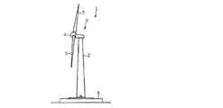
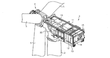
図6及び図7において、風力発電装置1は、基礎6上に立設される支柱2と、支柱2の上端に設置されるナセル3と、該ナセル3に対して回転自在に組付けられたロータヘッド4とを有している。ロータヘッド4は、複数枚(図示の例では3枚)の風車ブレード(風車翼)5が取り付けられている。ナセル3の内部において、ロータヘッド4には、増速機20及び発電機11が接続されている。
風車ブレード5に風が当たると、ロータヘッド4が回転し、該ロータヘッド4の回転が増速機20にて増速した状態で発電機11に伝達される。これにより、ロータヘッド4の(トルクはあるが)速度が遅い回転を、100倍程度の速さに増幅することができ、発電機11から効率的に発電出力を得ることができる。
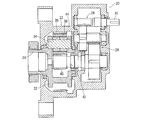
前記増速機20は、図8に示すように、初段に遊星歯車機構22を備えると共に、中段及び後段に平行軸歯車機構24、26を備える。初段の遊星歯車機構22は、入力軸28と一体化されたキャリヤ32、該キャリヤ32に固定された遊星ピン34、該遊星ピン34に回転自在に支持された遊星歯車36、該遊星歯車36が同時に噛合する内歯歯車38及び太陽歯車40から主に構成されている。この例では、太陽歯車40が遊星歯車機構22の出力軸42と一体化されると共に、内歯歯車38がケーシング44と一体化されている。中段及び後段の平行軸歯車機構24、26には、「平歯車」を用いた平行軸増速機構が採用されている。増速機20の出力軸30には、前述した発電機11が連結される。
なお、図7に示す符号12はトランス、13はコントローラ、14はインバータ、15はインバータクーラ、16は潤滑油クーラである。
風力発電設備は、その耐用期間が20年前後となるように設計される。このため、増速機についても基本的に20年前後の寿命が確保されることが要求される。
しかしながら、風力発電設備は、自然環境下に設置される設備であるため、ときに乱れた風や突風を受けたりすることがある。このような強い風が風車ブレードに掛かると増速機は入力側から巨大な負荷が掛けられた状態となってしまう。このため、(たとえガイドラインに沿った設計がなされている場合であっても)増速機内の各部が過度に速い回転速度で強制的に回転させられる状態が発生してしまい、トラブルの原因となることがあった。
増速機のトラブルは、一度発生するとその被害は深刻なものとなるため、信頼性の確保が重要視されている。一般に、増速機の信頼性を確保するにあたって有効な対策は、要するならば、設計時に各要素の安全率(セーフティファクタ)を大きくとることである。しかし、各要素の安全率を大きくとると、当然に増速機全体が大型化して重量も大きくなり、製造コスト、建設コストの増大を招くという問題が生じる。
本発明は、このような問題を解消するためになされたものであって、新たに見つけた「中間課題(後述)」を克服することによって、小型、軽量、低コストでありながら、信頼性が高く、寿命の長い風力発電用の増速機を提供することをその本来の課題としている。
本発明は、風力発電用の増速機において、該増速機の動力伝達系に備えられたヘリカルギヤと、該ヘリカルギヤが組み込まれた軸と、該軸に対して予め定められた大きさ以上のスラスト荷重が作用したときに該軸の軸方向の移動を許容する緩衝機構と、を備えた構成とすることにより、上記課題を解決したものである。
本発明の前記中間課題及びその解決原理は、公知のものではないため、ここで、本発明が着目した当該中間課題とその解決原理について、詳細に説明する。
風力発電設備の風車ブレードに、瞬間的に非常に強い風が掛かると、これに伴って増速機の各部に非常に強い加速トルクが発生する。しかしながら、増速機の先には高速で回転する発電機が負荷(イナーシャ)として連結されているため、増速機の各要素は、慣性によりこの加速トルクに瞬時に追随して回転速度を増大させることができない。結果として、加速トルクの立ち上りが急峻の場合は、各要素にこの急峻に立ち上がる加速トルクが、(恰も静止している各要素に対して掛かるように)瞬間的にそっくり掛かってしまうことになる。
本発明は、風力発電用の増速機のトラブルには、強風時に連続的に掛かる大きなトルクだけでなく、むしろ、このような「突風」等に起因して、増速機の各要素に瞬間的に(ピーク的に)発生する強い負荷あるいは衝撃が大きく影響していると推察し、こうした強い瞬間的な負荷あるいは衝撃を緩和することを「中間課題」として捉え、この中間課題を克服することによって、上記本来の課題を解決するという発想で創案された。
本発明に係る風力発電用の増速機では、その駆動系の中にヘリカルギヤを組み込んだ軸を配備するようにする。なお、本発明の「ヘリカルギヤ」の概念には、「ヘリカルピニオン」の概念を含む。
ヘリカルギヤは、歯筋がつる巻き線であるため、ヘリカルギヤが組み込まれた軸は、トルクを伝達する際に軸方向に該伝達トルクの大きさに比例してスラスト荷重が発生する。通常、ヘリカルギヤが組み込まれた軸は、このスラスト荷重を例えば「スラスト軸受」によって受け止め、軸に対してスラスト荷重に相当する反力を提供し、軸が軸方向に動かないようにしている。しかし、本発明では、この伝達トルクと該伝達トルクによって発生するスラスト荷重の関係をピークトルクの緩衝に巧みに利用するようにしている。即ち、本発明では、動力伝達系の中にヘリカルギヤが組み込まれた軸を配備すると共に、このヘリカルギヤが組み込まれた軸に対して予め定められた大きさ以上のスラスト荷重が作用したときに該軸の軸方向の移動を許容する緩衝機構が備えられている。
急に風力が増大してヘリカルギヤに瞬間的に急激なトルク上昇が発生すると、これに伴って軸に発生するスラスト荷重が急増し、この結果緩衝機構の機能により軸が瞬間的に軸方向に移動することが許容される。これにより、トルクを伝達するために発生していたヘリカルギヤの歯面同士の押し付け力が、当該軸の移動によって弱まり、弱まった分ヘリカルギヤによって伝達されるピークトルクの立ち上がりの急峻性が抑制される。
この結果、増速機内の各要素に瞬間的に強い負荷トルクが掛かるのを効果的に防止することができ、増速機内の弱部が破損したりするのを防止すると共に、増速機全体の寿命を増大させることができる。
本発明に係る風力発電用の増速機は、強風が吹きやすい地域や、風向きの安定しない地域、すなわち風の乱れが大きい地域に設置される風力発電設備に組み込まれる場合に、特に有効に機能する。
本発明によれば、小型、軽量、低コストでありながら、信頼性が高く、寿命の長い風力発電用の増速機を得ることが可能となる。
以下、図面に基づいて本発明の実施形態の一例を詳細に説明する。
本発明に係る増速機が組み込まれる風力発電設備の概略構成については、既に図6、図7を用いて説明したものと同様であるため、重複説明は省略し、以降、増速機自体の構成について詳細にする。
図1は、本発明の実施形態の一例を示す風力発電用の増速機50の全体断面図、図2は、その主要部を示す断面図である。
先ず、図1を参照して、この風力発電用の増速機50は、初段に遊星歯車機構52を備えると共に、中段及び後段に第1、第2平行軸歯車機構54、56を備える。入力軸58から入力されるロータヘッド(従来のロータヘッド4と同様:図6、7参照)の回転は、計3段の歯車機構52、54、56によって増速され、出力軸60から出力される。出力軸60には、発電機(従来の発電機11と同様:図7参照)が連結され、所定の発電がなされる。
本発明は、このうちの第1平行軸歯車機構54の第1ヘリカルピニオン(ヘリカルギヤ)90が組み込まれた第2中間軸92に適用されている(後に詳述)。
前記遊星歯車機構52は、入力軸58と一体化されたキャリヤ62、該キャリヤ62に両持ち支持された遊星ピン64、該遊星ピン64に回転自在に支持された3個(図2では1個のみ図示)の遊星歯車68、該遊星歯車68が同時に内接噛合する内歯歯車70、及び遊星歯車68が同時に外接噛合する太陽歯車72から主に構成されている。
この実施形態では、太陽歯車72は遊星歯車機構52の出力軸80に直接形成されており、内歯歯車70はケーシング74と一体化(固定)されている。風力によるロータヘッド(4)の回転は、入力軸58と一体化されたキャリヤ62から入力され、太陽歯車72を経て遊星歯車機構52の出力軸80から増速された回転が取り出される構成とされている。
遊星歯車機構52の出力軸80は、カップリング82を介して第1中間軸84と連結されている。第1中間軸84には第1ヘリカルギヤ86がキー88を介して連結されている。第1ヘリカルギヤ86は第1ヘリカルピニオン(本発明に係るヘリカルギヤに相当)90と噛合している。第1ヘリカルギヤ86と第1ヘリカルピニオン90が前述した第1平行軸歯車機構54を構成している。
第1ヘリカルピニオン90は第2中間軸92に直切り形成されている。第2中間軸92には第2ヘリカルギヤ94がキー96を介して円周方向に連結されている。第2ヘリカルギヤ94は、第1ヘリカルピニオン90の形成段差90Aと止めリング98との間に挟まれ、第2中間軸92と軸方向にも一体化されている。第2ヘリカルギヤ94は第2ヘリカルピニオン100と噛合している。第2ヘリカルピニオン100は当該増速機50の出力軸60に直切り形成されている。第2ヘリカルギヤ94と第2ヘリカルピニオン100が前述した第2平行軸歯車機構56を構成している。出力軸60は、軸受103、105を介してケーシング74により軸方向に移動不能に支持されている。
この実施形態では、第1ヘリカルギヤ86と第1ヘリカルピニオン90は、互いに噛合することによって第2中間軸92に(コイルばね112方向の)スラスト荷重Saが発生するようにねじれ方向が設定されている。また、第2中間軸92に組み込まれる第1ヘリカルピニオン90と第2ヘリカルギヤ94のねじれ方向を同一にすることにより、第2ヘリカルギヤ94と第2ヘリカルピニオン100が噛合することによって発生するスラスト荷重Sbが前記スラスト荷重Saと逆の方向に発生するように構成してある。スラスト荷重Sa>スラスト荷重Sbであるため、結局、第2中間軸92には、合成されたスラスト荷重(Sa-Sb)が発生する。
以下、図1に図2を合わせて参照して、第2中間軸92付近の構成を詳細に説明する。
第2中間軸92は、一対の第1、第2ラジアル軸受102、104を介してケーシング74に軸方向にのみ移動可能に両持ち支持されている。なお、第2中間軸92の付近ではケーシング74は、ケーシング本体74Aに、ケーシング74の一部を構成する組み付けブロック74B及び閉塞ブロック74Cがボルト(図示略:中心線のみ表示)にて一体化された構成とされている。閉塞ブロック74Cには閉塞蓋74C1が螺合されている。
第2中間軸92を支持している一方の前記第1ラジアル軸受102は、図2に拡大図示するように、外輪102Aに対して内輪102B及びころ102Cが軸方向(のみに)摺動できる構成とされている。より具体的には、第1ラジアル軸受102の外輪102Aは、ケーシング74の本体74Aに形成された突起部74A1とケーシングの一部を構成する組み付けブロック74Bとに挟まれた状態でケーシング74に固定されている。第1ラジアル軸受102のころ102Cは、内輪102Bの外周に該内輪102Bの突起部102B1に軸方向の移動が拘束された状態ではめ込まれている。内輪102Bは第2中間軸92に圧入・固定されている。
第2中間軸92を支持しているもう一方の第2ラジアル軸受104は、基本的には第1ラジアル軸受102と同様の構成を有し、詳細な図示は省略するが、第2中間軸92を軸方向に移動可能とする態様で該第2中間軸92を支持している。
以上の構成により、第2中間軸92は、ケーシング74(の本体74A)に対して軸方向(のみに)移動可能である。そして、この第2中間軸92の軸方向の移動を許容・制御しているのが緩衝機構110である。
この実施形態では、緩衝機構110は、コイルばね(緩衝体)112のほか、スライドプレート114、(スラスト軸受のほかラジアル軸受としての機能を有する)テーパころ軸受116を備える。
前記コイルばね(緩衝体)112は、自然長よりも圧縮された状態で組み込まれており、第2中間軸92に対して、第1ヘリカルピニオン90が回転するときに発生するスラスト荷重に抵抗する付勢力(第2中間軸92の移動を許容する方向と反対方向の付勢力:図2において左方向に第2中間軸92を押す力)を付与する。
前記スライドプレート114は、ケーシング74の組み付けブロック74Bに軸方向に形成された中空部74B1内で軸方向に摺動(移動)可能である。スライドプレート114は、該スライドプレート114の一方側(コイルばね112側)114Aから該コイルばね112の付勢力を、他方側(第2中間軸92側)114Bから該第2中間軸92のスラスト荷重を受け、このバランスにて、中空部74B1内の所定の位置に位置決めされる。なお、このスライドプレート114は、他方側の一部114B1が組み付けブロック74Bの突部74B2に当接可能とされている。このため、第2中間軸92からのスラスト荷重(図2において右方向の荷重)が所定値So未満のときには、たとえスラスト荷重よりもコイルばね112の付勢力の方が強くても、スライドプレート114は、この突部74B2よりも第2中間軸92側に移動ができないように構成されている。したがって、第2中間軸92に発生するスラスト荷重が所定値So未満の場合には、第2中間軸92は、該スラスト荷重に等しい反力のみをテーパころ軸受116を介してスライドプレート114側から受けることになるため、第2中間軸92の回転トルクの伝達によって発生するスラスト荷重以上に大きな応力が第2中間軸92に発生することはない。
前記テーパころ軸受116は、スライドプレート114と第2中間軸92の段差部92Aとの間に配置されることで、該第2中間軸92のスラスト荷重をスライドプレート114に伝える「スラスト軸受」としての機能を有する。すなわち、この実施形態では、第2中間軸92のコイルばね112側のラジアルトルクのほぼ全量を、第1ラジアル軸受102にて受けているため、当該テーパころ軸受116にはラジアル軸受としての機能はほとんど持たせていない(具体的にはテーパころ軸受116の外周は、若干遊ばせる設計としてある)。この意味で、テーパころ軸受116は、スラスト荷重を専用に受け持つ「スラスト軸受」に置き換えることも可能である。構造的にも、例えば転動体を有しないメタル軸受とすることもできる。この実施形態のように、ラジアル荷重を受け持つ第1ラジアル軸受102とスラスト荷重を受け持つテーパころ軸受116をそれぞれ別の軸受で構成するようにすると、第2中間軸92を(軸ぶれすることなく)軸方向に「のみ」移動させ得る点で優れる。但し、本発明では、例えば、(第1ラジアル軸受102及びテーパころ軸受116の代わりに)ラジアル荷重及びスラスト荷重の両方を受けられる単一の軸受を組み込む構成とすることを禁止するものではない。
次に、この実施形態に係る風力発電用の増速機50の作用を説明する。
風車ブレード(5)の回転は、増速機50の入力軸58に伝達される。入力軸58の回転はキャリヤ62を介して遊星歯車68の公転として遊星歯車機構52に入力され、遊星歯車68、内歯歯車70、太陽歯車72の3者の相対回転により、増速された回転が太陽歯車72から遊星歯車機構52の出力軸80へと出力される。
遊星歯車機構52の出力軸80の回転は、カップリング82を介して第1平行軸歯車機構54の第1中間軸84に伝達され、キー88を介して第1ヘリカルギヤ86に伝達される。第1ヘリカルギヤ86の回転は、第1ヘリカルピニオン90に伝達され、これにより第2中間軸92が回転する。
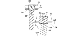
図3に模式的に示すように、今、ある入力トルクTが入力軸58から入力されると、第1平行軸歯車機構54の第1ヘリカルギヤ86と第1ヘリカルピニオン90が噛合することによって第2中間軸92には、(コイルばね112方向の)スラスト荷重Saが発生する。また、この実施形態では、第2中間軸92に組み込まれる第1ヘリカルピニオン90と第2ヘリカルギヤ94のねじれ方向を同一にすることにより、第2ヘリカルギヤ94と第2ヘリカルピニオン100が噛合することによって発生するスラスト荷重Sbが前記スラスト荷重Saと相殺されるように構成している。その結果、スラスト荷重Sa>スラスト荷重Sbであることから、第2中間軸92には、入力軸58から入力トルクTが入力されると、合成されたスラスト荷重(Sa-Sb)が発生する。
第2中間軸92に作用するスラスト荷重(Sa-Sb)は、入力トルクTの増減に連動・比例して増減する。入力トルクTが(強度上問題とならない)比較的小さいT1であるときは、発生するスラスト荷重(Sa1-Sb1)も所定値Soより小さく、コイルばね112の付勢力Fcの方が大きいため(So<Fc)、図2に示されるように、スライドプレート114は組み付けブロック74Bの突部74B2に当接した状態となる。このため、第2中間軸92は、常時、発生したスラスト荷重(Sa-Sb)と等しい大きさのスラスト反力を、テーパころ軸受116を介して受けることとなり、結果として、軸方向に動かない状態を維持する。
ここまでが、通常時の作用となる。
しかし、入力トルクTが突風等によって突然大きなT2となり、発生するスラスト荷重(Sa2-Sb2)が所定値Soを超え、コイルばね112の付勢力Fcに打ち勝つようになると(So≧Fc)、コイルばね112が圧縮され、その結果増大された付勢力Fc’とスラスト荷重(Sa2-Sb2)が釣り合う位置までスライドプレート114がコイルばね112方向に動く。
この結果、以下のような作用がなされる。
即ち、増速機50の出力軸60には、イナーシャの大きな発電機(11)が接続されている。このため、(もし、本実施形態のような構成とされていないと)入力軸58からこの突然増大したトルクT2が入力されてきても、それに追随して出力軸60の回転速度は急には速くはなれないため、増速機50の各要素は、この瞬間的に増大したトルクを、あたかも停止状態で受け止めるような態様で受け止めざるを得ないことになる。
しかしながら、この実施形態では、(再び図3を参照しながら説明すると)このような急峻なトルク増大があると、前述したように、第2中間軸92自体がコイルばね112側に軸方向に移動することから、一瞬、第1ヘリカルピニオン90の歯面90Aが第1ヘリカルギヤ86の歯面86Aから離れる方向に動くため(破線参照:実際は離れることはない)、伝達トルクの急峻な立ち上がりが弱められる。換言するならば、増速機50の下流側に伝達されるべきトルクの一部が、緩衝機構110のコイルばね(緩衝体)112を圧縮するエネルギとして消費されることになる。
一方、第2ヘリカルギヤ94と第2ヘリカルピニオン100との噛合部においては、第2ヘリカルギヤ94が駆動、第2ヘリカルピニオン100が従動であるため、第2中間軸92がコイルばね112の側に瞬間的に動くことによって、やはり伝達トルクの急駿な立ち上がりが弱められる作用が得られ、これにより第2中間軸92から出力軸60に伝達されるピークトルクの発生が抑えられる。即ち、第2中間軸92が(コイルばね112の方向に)軸方向に動くことによって、増速機50の各部に瞬間的に発生する負荷(ピークトルク)を、極めて効果的に軽減することができる。
本実施形態に係る構成は、入力軸58側から継続的(連続的)に強いトルクが入力されて来た場合には、当該継続的に入力されてくるトルクについては、これを減じることはできないが、風力発電設備の場合、突風等によって瞬間的に強い負荷が掛かることが、非常にしばしば発生する。そのため、このような瞬間的なピークトルクの立ち上がりを抑制できる効果は、極めて大きく、寿命増大に大きく貢献する。
本発明は、様々なバリエーションが考えられる。
例えば、上記実施形態においては、緩衝機構としてコイルばね112を使用したものが採用されていたが、本発明に係る緩衝機構は、要は、ヘリカルギヤの組み込まれる軸に作用するスラスト荷重が予め定められた大きさ以上となったときに、該軸の軸方向の移動を許容するようになっていれば良く、種々の構成が採用できる。例えば、図4に示されるように、緩衝体として、皿ばね150を用いることもできる。なお、この例では、これに伴って閉塞ブロック74Dと閉塞蓋74D1の形状を先の実施形態と若干変更している。なお、このように緩衝体として、コイルばね112や皿ばね150のような「ばね系」の緩衝体を採用する場合には、例えば、ばね定数の異なる複数のばねを直接(または間にスライドプレートを挟んで)直列に配置するようにすると、ピークトルクに対する適用幅(どの程度のピークトルクが掛かったときにどの程度の移動(スライド)をさせるか)をより広げる設計ができる場合がある。その他の構成は、先の実施形態と同様であるため、図中で同一または機能的に同一に部位に同一の符号を付している。
また、例えば図5に示されるように、閉塞ブロック74E内に構成したシリンダ部74E1と、このシリンダ部74E1内で摺動可能とされると共に、スライドプレート114と一体化されたピストン156と、を備えた油圧(液圧)シリンダ機構160にて緩衝機構を構成するようにしてもよい(空圧シリンダ機構であってもよい)。この場合、切り換え弁162、あるいは絞り164等を適宜に組み合わせることにより、移動開始のタイミング、或いは移動ストローク等を一層きめ細かく調整することができる油圧回路を構築できる。なお、図5の描写は、このことを極めて簡易に模式的に示したものであって実際の油圧回路とは完全には一致していない。
なお、上記実施形態においては、第2中間軸92に対して軸方向の動きを許容する構成を採用していたが、既に述べたように、本発明において軸方向の移動を許容する軸は、この例に限らず、例えば、上記実施形態の構成で言うならば、第1中間軸、あるいは出力軸を軸方向に移動させるような構成としても良い。また、複数の軸(例えば第1中間軸と第2中間軸、第2中間軸と出力軸、第1中間軸と出力軸、あるいは第1、第2中間軸及び出力軸の全て)を軸方向に動かせるような構成としても良い。複数の軸を移動可能に構成する場合、例えば、各軸で移動を開始する閾値を変える(ずらす)ことで、抑制しようとするピークトルクのターゲット範囲を広げることができる。
また、上記実施形態においては、第2中間軸92の一方向の移動に対してのみ、スラスト荷重の吸収効果が得られるようにしていたが、例えば、1つの軸の両端に同様な構造を組み込むことにより(あるいは片側で両方向のスラストを吸収できるように構成したりすることにより)、両方向においてスラスト荷重の吸収効果が発揮されるようにしても良い。即ち、風力発電設備の増速機の場合、(通常ナセルのノーズヘッドを風上に向けるヨー制御が行われるため)風車ブレードが逆回転することはまれである。しかし、たとえ同じ方向に風車ブレードが回転していても(増速機の入力軸の回転方向は同一でも)減速時には(特に急減速時には)発電機の慣性により逆トルクが作用することがある。この場合、駆動・被駆動関係が逆転し、スラスト荷重の発生する向きも逆になる。このとき、(たとえ発生する逆トルクの絶対値自体はそれほど大きくなくても)バックラッシが反転することによる衝撃が寿命に影響する恐れがある。軸を逆方向に移動できるようにしておくことにより、この衝撃を和らげることができる。
なお、本発明においては、増速機50の動力伝達系にヘリカルギヤを配置し、該ヘリカルギヤの噛合によって発生するスラスト荷重を巧みに利用して、ピークトルクを低減するようにしていた。ここで噛合によってスラスト荷重が発生する歯車としては、ヘリカルギヤのほかに、例えば、ベベルギヤ、或いはハイポイドギヤ等がある。しかしながら、これらのギヤは、一方の軸が軸方向に移動すると、「歯当たり」自体が大きく異なってくるため、好ましくない。但し、動力伝達系にヘリカルギヤの組み込まれた軸を備えるものであれば、増速機構自体の構成については、上記実施形態のものに限定されず、どのような構成であってもよい。
本発明は、風力発電設備の増速機に利用可能である。
2011年2月7日に出願された日本国出願番号2011-023560の明細書、図面及び特許請求の範囲における開示は、その全体がこの明細書中に参照により援用されている。
1…風力発電設備
3…ナセル
4…ロータヘッド
5…風車ブレード
11…発電機
50…増速機
52…遊星歯車機構
54…第1平行軸歯車機構
56…第2平行軸歯車機構
58…入力軸
60…出力軸
86…第1ヘリカルギヤ
90…第1ヘリカルピニオン(ヘリカルギヤ)
92…第2中間軸(軸)
94…第2ヘリカルギヤ
100…第2ヘリカルピニオン
102、104…第1、第2ラジアル軸受
110…緩衝機構
112…コイルばね(緩衝体)
114…スライドプレート
116…テーパころ軸受
3…ナセル
4…ロータヘッド
5…風車ブレード
11…発電機
50…増速機
52…遊星歯車機構
54…第1平行軸歯車機構
56…第2平行軸歯車機構
58…入力軸
60…出力軸
86…第1ヘリカルギヤ
90…第1ヘリカルピニオン(ヘリカルギヤ)
92…第2中間軸(軸)
94…第2ヘリカルギヤ
100…第2ヘリカルピニオン
102、104…第1、第2ラジアル軸受
110…緩衝機構
112…コイルばね(緩衝体)
114…スライドプレート
116…テーパころ軸受
Claims (5)
- 風力発電用の増速機において、
該増速機の動力伝達系に備えられたヘリカルギヤと、
該ヘリカルギヤが組み込まれた軸と、
該軸に対して予め定められた大きさ以上のスラスト荷重が作用したときに該軸の軸方向の移動を許容する緩衝機構と、
を備えたことを特徴とする風力発電用の増速機。 - 請求項1において、
前記緩衝機構が、前記軸に対して、ばねによって前記移動を許容する方向と反対方向に付勢力を与える構成とされている
ことを特徴とする風力発電用の増速機。 - 請求項1において、
前記緩衝機構が、前記軸に対して、絞りを有する液圧又は空圧シリンダによって前記移動を許容する方向と反対方向に付勢力を与える構成とされている
ことを特徴とする風力発電用の増速機。 - 請求項1~3のいずれかにおいて、
前記緩衝機構が、前記軸の軸方向に移動可能であって前記軸のスラスト荷重を受けるスライドプレートと、
該スライドプレートと前記軸との間に配置され、該軸のスラスト荷重を前記スライドプレートに伝えるスラスト軸受とを備えている
ことを特徴とする風力発電用の増速機。 - 請求項4において、
前記スラスト軸受がテーパころ軸受であり、且つ
該テーパころ軸受のほかに、自身の内輪及び転動体が前記軸と共に軸方向に移動可能な一対のラジアル軸受を備えた
ことを特徴とする風力発電用の増速機。
Priority Applications (1)
| Application Number | Priority Date | Filing Date | Title |
|---|---|---|---|
| CN201180063600.7A CN103370536B (zh) | 2011-02-07 | 2011-11-21 | 风力发电用增速器 |
Applications Claiming Priority (2)
| Application Number | Priority Date | Filing Date | Title |
|---|---|---|---|
| JP2011-023560 | 2011-02-07 | ||
| JP2011023560A JP5676293B2 (ja) | 2011-02-07 | 2011-02-07 | 風力発電用の増速機 |
Publications (1)
| Publication Number | Publication Date |
|---|---|
| WO2012108086A1 true WO2012108086A1 (ja) | 2012-08-16 |
Family
ID=46638315
Family Applications (1)
| Application Number | Title | Priority Date | Filing Date |
|---|---|---|---|
| PCT/JP2011/076768 Ceased WO2012108086A1 (ja) | 2011-02-07 | 2011-11-21 | 風力発電用の増速機 |
Country Status (3)
| Country | Link |
|---|---|
| JP (1) | JP5676293B2 (ja) |
| CN (1) | CN103370536B (ja) |
| WO (1) | WO2012108086A1 (ja) |
Citations (3)
| Publication number | Priority date | Publication date | Assignee | Title |
|---|---|---|---|---|
| JPH07229471A (ja) * | 1994-02-18 | 1995-08-29 | Mitsubishi Heavy Ind Ltd | 風力発電用増速機 |
| JPH10339294A (ja) * | 1997-06-09 | 1998-12-22 | Tochigi Fuji Ind Co Ltd | 遠心式流体機械 |
| JP2008106894A (ja) * | 2006-10-27 | 2008-05-08 | Mitsubishi Heavy Ind Ltd | バックラッシュ除去装置 |
Family Cites Families (2)
| Publication number | Priority date | Publication date | Assignee | Title |
|---|---|---|---|---|
| JPH0989051A (ja) * | 1995-09-27 | 1997-03-31 | Mita Ind Co Ltd | 回転伝達機構 |
| JP5184035B2 (ja) * | 2007-10-05 | 2013-04-17 | 株式会社マキタ | 電動工具の減速機構 |
-
2011
- 2011-02-07 JP JP2011023560A patent/JP5676293B2/ja not_active Expired - Fee Related
- 2011-11-21 CN CN201180063600.7A patent/CN103370536B/zh not_active Expired - Fee Related
- 2011-11-21 WO PCT/JP2011/076768 patent/WO2012108086A1/ja not_active Ceased
Patent Citations (3)
| Publication number | Priority date | Publication date | Assignee | Title |
|---|---|---|---|---|
| JPH07229471A (ja) * | 1994-02-18 | 1995-08-29 | Mitsubishi Heavy Ind Ltd | 風力発電用増速機 |
| JPH10339294A (ja) * | 1997-06-09 | 1998-12-22 | Tochigi Fuji Ind Co Ltd | 遠心式流体機械 |
| JP2008106894A (ja) * | 2006-10-27 | 2008-05-08 | Mitsubishi Heavy Ind Ltd | バックラッシュ除去装置 |
Also Published As
| Publication number | Publication date |
|---|---|
| CN103370536B (zh) | 2015-09-02 |
| JP2012163033A (ja) | 2012-08-30 |
| JP5676293B2 (ja) | 2015-02-25 |
| CN103370536A (zh) | 2013-10-23 |
Similar Documents
| Publication | Publication Date | Title |
|---|---|---|
| JP5425742B2 (ja) | 遊星歯車減速機 | |
| WO2010135754A3 (de) | Energiegewinnungsanlage, insbesondere windkraftanlage | |
| WO2011027427A1 (ja) | 風力発電装置 | |
| DK2604857T3 (en) | Modular gear unit for a wind turbine | |
| JP5520247B2 (ja) | 風力発電設備の減速装置及び出力ピニオンを備えた減速装置 | |
| US9074661B2 (en) | Drive unit with drive motor and planetary gear mechanism | |
| JP5654949B2 (ja) | 風力発電設備の動力伝達装置 | |
| JP5148346B2 (ja) | 風力発電装置 | |
| US20190383359A1 (en) | Wind turbine with two-stage star compound gear train | |
| US20150038284A1 (en) | Epicyclic gearing with a gearing housing | |
| JP5877222B2 (ja) | 風力発電設備の動力伝達装置 | |
| JP5352510B2 (ja) | 風力発電用の増速機 | |
| JP5676293B2 (ja) | 風力発電用の増速機 | |
| JP2021019500A (ja) | 動力伝達装置 | |
| JP2010216562A (ja) | 自然エネルギの回収システム用の減速装置 | |
| WO2013035865A1 (ja) | 風力発電用の増速機 | |
| WO2012127736A1 (ja) | 風力発電用の増速機 | |
| JP5832206B2 (ja) | 風力発電用の増速機 | |
| JP2013072526A (ja) | ロックドトレーン機構を備えた風力発電用の増速機 | |
| JP2019526012A (ja) | 風力タービン用のナセル及びロータ並びに方法 | |
| JP6138012B2 (ja) | 風力発電設備のヨー駆動システム | |
| CN212672367U (zh) | 一种垂直轴风力发电机的增速箱 | |
| WO2013038495A1 (ja) | 風力発電用の増速機 | |
| JP5836036B2 (ja) | 風力発電用の増速機 | |
| JP5738132B2 (ja) | 風力発電用の増速機 |
Legal Events
| Date | Code | Title | Description |
|---|---|---|---|
| 121 | Ep: the epo has been informed by wipo that ep was designated in this application |
Ref document number: 11858033 Country of ref document: EP Kind code of ref document: A1 |
|
| NENP | Non-entry into the national phase |
Ref country code: DE |
|
| 122 | Ep: pct application non-entry in european phase |
Ref document number: 11858033 Country of ref document: EP Kind code of ref document: A1 |