WO2012108017A1 - 投射型映像表示装置 - Google Patents
投射型映像表示装置 Download PDFInfo
- Publication number
- WO2012108017A1 WO2012108017A1 PCT/JP2011/052783 JP2011052783W WO2012108017A1 WO 2012108017 A1 WO2012108017 A1 WO 2012108017A1 JP 2011052783 W JP2011052783 W JP 2011052783W WO 2012108017 A1 WO2012108017 A1 WO 2012108017A1
- Authority
- WO
- WIPO (PCT)
- Prior art keywords
- liquid crystal
- crystal panel
- flexible substrate
- light valve
- cooling air
- Prior art date
- Legal status (The legal status is an assumption and is not a legal conclusion. Google has not performed a legal analysis and makes no representation as to the accuracy of the status listed.)
- Ceased
Links
Images



Classifications
-
- G—PHYSICS
- G03—PHOTOGRAPHY; CINEMATOGRAPHY; ANALOGOUS TECHNIQUES USING WAVES OTHER THAN OPTICAL WAVES; ELECTROGRAPHY; HOLOGRAPHY
- G03B—APPARATUS OR ARRANGEMENTS FOR TAKING PHOTOGRAPHS OR FOR PROJECTING OR VIEWING THEM; APPARATUS OR ARRANGEMENTS EMPLOYING ANALOGOUS TECHNIQUES USING WAVES OTHER THAN OPTICAL WAVES; ACCESSORIES THEREFOR
- G03B21/00—Projectors or projection-type viewers; Accessories therefor
- G03B21/14—Details
- G03B21/16—Cooling; Preventing overheating
-
- H—ELECTRICITY
- H04—ELECTRIC COMMUNICATION TECHNIQUE
- H04N—PICTORIAL COMMUNICATION, e.g. TELEVISION
- H04N9/00—Details of colour television systems
- H04N9/12—Picture reproducers
- H04N9/31—Projection devices for colour picture display, e.g. using electronic spatial light modulators [ESLM]
- H04N9/3141—Constructional details thereof
- H04N9/3144—Cooling systems
Definitions
- the present invention relates to a projection type video display.
- a projection-type image display apparatus that forms an optical image by performing light intensity modulation according to an image signal with light valves such as a liquid crystal panel to light from a light source such as a high pressure mercury lamp Liquid crystal projectors, rear projection display devices, etc.
- a projection type video display device compatible with color video white light from a light source is separated into a plurality of colors (for example, 3 colors of R, G, B) by color separation means, and light bulbs (liquid crystal The panel is illuminated to form an optical image of each color light, and an optical image of each color light is synthesized by a color combining prism and projected by a projection lens.
- a high output light source lamp is used in order to increase the brightness of the display screen.
- the cooling technology of the optical parts has become important.
- the liquid crystal panel is formed immediately after the air discharge port of the cooling fan as a shape of an air guide that guides the cooling air from the cooling fan to the liquid crystal panel.
- a configuration is generally disclosed in which the cross-sectional area of the ventilation passage is substantially the same.
- a cooling fan and an air guide are disposed under a light valve (liquid crystal panel), and the liquid crystal panel is cooled from the bottom to the top. Further, a flexible substrate for transmitting a drive signal is connected to the upper portion of the liquid crystal panel, and the other end of the flexible substrate is connected to a drive substrate for drive.
- the present invention has been made to solve the above-mentioned problems, and its object is to eliminate stagnation of cooling air passing through a light valve (liquid crystal panel), to efficiently cool the light valve and to achieve projection with excellent reliability.
- Type image display apparatus is to eliminate stagnation of cooling air passing through a light valve (liquid crystal panel), to efficiently cool the light valve and to achieve projection with excellent reliability.
- a projection type video display apparatus comprising: a light source; a light valve for modulating light emitted from the light source to form an optical image; and a projection unit for projecting an optical image formed by the light valve.
- the width of the vent is at least half the width of the effective light area of the light valve, and the length of the vent is from the lower surface side through the through hole through which the flexible substrate provided in the drive substrate passes. It arranges so that all may become 2 mm or more on the upper surface side.
- the present invention it is possible to provide a projection-type image display device which is improved in the cooling performance of the light valve and is excellent in reliability because the stagnation of the cooling air passing through the light valve (liquid crystal panel) is eliminated.
- FIG. 2 is a perspective view of the vicinity of a flexible substrate connecting a liquid crystal panel and a drive substrate.
- the figure which shows the shape of a flexible substrate ((a) is a prior art example, (b) is a present Example).
- the figure which analyzed the flow of the cooling air of the liquid crystal panel vicinity ((a) is a prior art example, (b) is a present Example).
- FIG. 1 is a side view showing a configuration of a cooling system in the vicinity of a light valve (liquid crystal panel) as an embodiment of a projection type video display device.
- reference numeral 1 denotes a liquid crystal panel as a light valve (only one out of three for R, G and B colors is shown for simplicity)
- 2 denotes a color combining prism such as a cross dichroic prism
- 3 denotes a projection
- a projection unit such as a lens
- 4 is an incident side polarization plate
- 5 is an emission side polarization plate.
- 6 is a drive substrate for driving the liquid crystal panel 1
- 7 is a flexible substrate (flexible cable) for transmitting a drive signal from the drive substrate 6 to the liquid crystal panel 1
- 8 is a connector for connecting the flexible substrate 7 to the drive substrate
- 9 is a flexible substrate 7 is a through hole provided in the drive substrate 6 in order to pass 7 toward the connector 8 side.
- 11 indicates a cooling unit
- 12 indicates a cooling fan that generates cooling air
- 13 indicates an air guiding duct that guides the cooling air to the liquid crystal panel 1
- 14 indicates a cooling air outlet
- 15 indicates the flow of the cooling air.
- Illumination light generated from a light source is separated into three color lights (R, G, B) by a color separation unit (not shown) and is incident on the corresponding liquid crystal panel 1.
- the liquid crystal panel 1 modulates the incident light with the drive signal supplied from the drive substrate 6 to form an optical image according to the video signal.
- the optical images formed by the liquid crystal panels 1 are combined by the color combining prism 2 and enlarged and projected from the projection unit 3 onto a screen (not shown) or the like.
- the cooling unit 11 supplies the cooling air 15 in order to cool the liquid crystal panel 1 which generated heat by irradiating the incident light.
- the cooling fan 12 is disposed at a position away from the liquid crystal panel 1, guides the cooling air 15 to the lower position of the liquid crystal panel 1 by the air guide duct 13, and blows out from the outlet 14 toward the liquid crystal panel 1.
- the cooling air 15 efficiently cools the heat generating portion of the liquid crystal panel 1 by flowing from the lower portion to the upper portion along the panel surface of the liquid crystal panel 1.
- the cooling air after cooling the liquid crystal panel 1 is discharged to the upper side of the drive substrate 6 through the through holes 9 of the drive substrate 6.
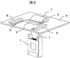
- FIG. 2 is a perspective view of the vicinity of the flexible substrate connecting the liquid crystal panel and the drive substrate.
- the flexible substrate 7 for one liquid crystal panel 1 is illustrated, but the same applies to the other two liquid crystal panels and the flexible substrate.
- a flexible substrate 7 for transmitting a drive signal to the liquid crystal panel 1 is connected to a connector 8 provided on a drive substrate 6 disposed above the liquid crystal panel 1. Since the connector 8 is disposed on the upper surface side of the drive substrate 6, that is, on the opposite side to the liquid crystal panel 1, the flexible substrate 7 is connected to the connector 8 through the through hole 9 provided in the drive substrate 6. At that time, the flexible substrate 7 is substantially linear in the section from the liquid crystal panel 1 to the through hole 9 (linear section), but is deformed and arranged in a curved shape in the section from the through hole 9 to the connector 8 (curved section ).
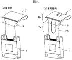
- FIG. 3 is a view showing the shape of the flexible substrate, in which (a) shows a conventional example and (b) shows the case of this embodiment.
- the wiring surface which is the main surface is entirely closed (i.e., a shape without holes).
- the flexible substrate 7 of the present embodiment shown in (b) is characterized in that vent holes 20 for passing cooling air are provided on the wiring surface which is the main surface.
- the ventilation holes 20 are formed at substantially the center of the flexible substrate 7 in the width direction, and the shape thereof is a rectangular shape (or an elliptical shape) extended in the longitudinal direction of the flexible substrate 7.
- vent holes 20 are formed across the upper and lower surface sides of the through holes 9 of the drive substrate 6 (that is, formed across the linear portion 7a and the curved portion 7b of the flexible substrate 7) Is preferred. Although the width of the wiring portion of the flexible substrate 7 is narrowed by forming the vent holes 20, it is sufficient to widen the entire width of the flexible substrate 7 when the wiring capacitance is insufficient.
- FIG. 4 is a diagram in which the flow of cooling air in the vicinity of the liquid crystal panel is analyzed, in which (a) shows a conventional example and (b) shows the case of this embodiment.
- the flows of the cooling air in the case of using the flexible substrates 7 ′ and 7 shown in FIGS. 3A and 3B are compared by fluid analysis.
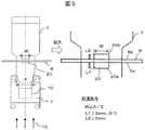
- FIG. 5 is a view for explaining the dimensions of the vent holes 20 provided in the flexible substrate, and shows the vicinity of the vent holes in an enlarged manner.
- the flexible substrate 7 connected to the liquid crystal panel 1 is disposed to penetrate the drive substrate 6.
- the ventilation holes 20 provided in the flexible substrate 7 are substantially rectangular, and are formed substantially at the central position in the width direction of the flexible substrate 7 and in the vicinity of the intersecting position with the drive substrate 6 in the longitudinal direction.
- the width W of the vent holes 20 is preferably W ⁇ A / 2 with respect to the width A of the effective light area 10 of the liquid crystal panel 1. This corresponds to a size that can pass through the vent holes 20 when the air cooled the effective light region 10 of the liquid crystal panel 1 goes straight.
- the length of the vent hole 20 is L1 from the lower surface 6a of the drive substrate 6 to the end 20a of the vent hole 20, and L2 from the upper surface 6b of the drive substrate 6 to the end 20b of the vent hole 20. At this time, it is preferable to set L122 mm and L2 ⁇ ⁇ 2 mm, and the reason will be described below.
- FIG. 6 is a diagram showing the relationship between the size of the vent and the passing wind speed. It is the result of analyzing the passing wind speed V of the cooling wind which passes the liquid crystal panel 1 by making length L 1 and L 2 of the ventilation hole 20 shown in FIG. 5 into a parameter.
- the opening area of the ventilation holes 20 is increased, and the passing wind speed V of the cooling air is also increased.
- stagnation vortex
- the preferable length of the vent hole 20 is L1 ⁇ 2 mm and L2 ⁇ 2 mm.
- L1 + L2> 4 mm
- the size of the ventilation holes 20 it is preferable to secure an opening of 2 mm or more in both the upper and lower directions from the upper and lower surfaces of the drive substrate 6.
- the cooling air having passed through the liquid crystal panel does not stay in the space surrounded by the drive substrate and the flexible substrate, and the cooling performance of the liquid crystal panel is improved and the projection type image display device is excellent in reliability.
- the configuration in which three liquid crystal panels are used is described in this embodiment, the same applies to the case where one liquid crystal panel is used. Furthermore, the same applies to the case where another light valve is used instead of the liquid crystal panel.
Landscapes
- Engineering & Computer Science (AREA)
- Multimedia (AREA)
- Signal Processing (AREA)
- Physics & Mathematics (AREA)
- General Physics & Mathematics (AREA)
- Transforming Electric Information Into Light Information (AREA)
- Projection Apparatus (AREA)
- Liquid Crystal (AREA)
Abstract
投射型映像表示装置は、液晶パネル(1)を駆動するドライブ基板(6)と、ドライブ基板(6)から液晶パネル(1)へ駆動信号を伝達するフレキシブル基板(7)と、液晶パネル(1)に冷却風を供給する冷却ユニット(11)とを有し、フレキシブル基板(7)には、冷却ユニット(11)から供給される冷却風の通風孔(20)を設ける。好ましくは通風孔(20)の幅は、液晶パネル(1)の有効光領域の幅の1/2以上とし、通風孔(20)の長さは、フレキシブル基板(7)を通す貫通孔(9)から下面側及び上面側にいずれも2mm以上となるように配置する。これにより、液晶パネル(1)を通過した冷却風の滞留をなくし、液晶パネル(1)を効率良く冷却し信頼性に優れた投射型映像表示装置を提供する。
Description
本発明は、投射型映像表示装置に関する。
従来、高圧水銀ランプなどの光源からの光に対し、液晶パネルなどのライトバルブにより映像信号に応じて光強度変調を行って光学像を形成し、スクリーンなどに拡大投射する投射型映像表示装置(液晶プロジェクタや背面投射型ディスプレイ装置等)が知られている。特にカラー映像対応の投射型映像表示装置においては、光源からの白色光を色分離手段で複数色(例えばR,G,Bの3色)に分離し、それぞれの色光を対応するライトバルブ(液晶パネル)に照射して各色光の光学像を形成し、色合成プリズムによって各色光の光学像を合成し投射レンズにて投射する構成となっている。
近年の投射型映像表示装置では表示画面の高輝度化を図るため、高出力の光源ランプを使用している。これに伴い、装置を構成するライトバルブなどの光学部品の温度上昇を抑えるため、光学部品の冷却技術が重要になっている。例えば特許文献1では、液晶パネルの冷却と表示装置の小型化を実現するために、冷却ファンからの冷却風を液晶パネルに導く導風路の形状として、冷却ファンの空気吐出口直後から液晶パネルまで概ね同一の通風路断面積とした構成が開示されている。
従来の投射型映像表示装置は、ライトバルブ(液晶パネル)の下に冷却ファンや導風路を配置し、液晶パネルを下部から上部に向けて冷却する構成となっている。また、液晶パネルの上部には駆動信号を伝達するためのフレキシブル基板が接続されており、該フレキシブル基板の他端は、駆動用ドライブ基板と接続されている。特許文献1のように、冷却風により液晶パネルを下面から上面に向けて冷却する場合、液晶パネルを通過した冷却風は、ドライブ基板とフレキシブル基板で囲われた液晶パネルの上部空間に滞留しやすくなる。冷却風が滞留すると、液晶パネルの冷却効率が低下するだけでなく、冷却ファンの圧力損失を引き起こしたり、冷却風に混じった塵埃が液晶パネルの有効光領域に付着し、画質の劣化を引き起こす要因となる。表示装置の小型化が進むほどドライブ基板と液晶パネルは近接し、前記冷却風の滞留が及ぼす影響は大きくなる。
本発明は、上記問題点を解決するためになされたもので、その目的は、ライトバルブ(液晶パネル)を通過した冷却風の滞留をなくし、ライトバルブを効率良く冷却し信頼性に優れた投射型映像表示装置を提供することにある。
本発明は、光源と、該光源から出射された光を変調し光学像を形成するライトバルブと、該ライトバルブで形成された光学像を投射する投射部とを備えた投射型映像表示装置において、前記ライトバルブを駆動するドライブ基板と、該ドライブ基板から前記ライトバルブへ駆動信号を伝達するフレキシブル基板と、前記ライトバルブに冷却風を供給する冷却ユニットとを有し、前記フレキシブル基板には、前記冷却ユニットから供給される冷却風の通風孔を設けた構成とする。
好ましくは前記通風孔の幅は、前記ライトバルブの有効光領域の幅の1/2以上とし、前記通風孔の長さは、前記ドライブ基板に設けた前記フレキシブル基板を通す貫通孔から下面側及び上面側にいずれも2mm以上となるように配置する。
本発明によれば、ライトバルブ(液晶パネル)を通過した冷却風の滞留がなくなり、ライトバルブの冷却性能が向上し信頼性に優れた投射型映像表示装置を提供することができる。
以下、本発明の実施形態について図面を参照して説明する。
図1は、投射型映像表示装置の一実施例として、ライトバルブ(液晶パネル)近傍の冷却系の構成を示す側面図である。図1において、1はライトバルブとしての液晶パネル(R,G,B色用の3枚のうち、簡単のために1枚のみ示す)、2はクロスダイクロイックプリズムなどの色合成プリズム、3は投射レンズなどの投射部、4は入射側偏光板、5は出射側偏光板である。6は液晶パネル1を駆動するドライブ基板、7はドライブ基板6から液晶パネル1へ駆動信号を伝達するフレキシブル基板(フレキシブルケーブル)、8はフレキシブル基板7をドライブ基板に接続するコネクタ、9はフレキシブル基板7をコネクタ8側に通すためにドライブ基板6に設けた貫通孔である。また、11は冷却ユニット、12は冷却風を発生する冷却ファン、13は冷却風を液晶パネル1まで導く導風ダクト、14は冷却風の吹出し口、15は冷却風の流れを示す。
図1は、投射型映像表示装置の一実施例として、ライトバルブ(液晶パネル)近傍の冷却系の構成を示す側面図である。図1において、1はライトバルブとしての液晶パネル(R,G,B色用の3枚のうち、簡単のために1枚のみ示す)、2はクロスダイクロイックプリズムなどの色合成プリズム、3は投射レンズなどの投射部、4は入射側偏光板、5は出射側偏光板である。6は液晶パネル1を駆動するドライブ基板、7はドライブ基板6から液晶パネル1へ駆動信号を伝達するフレキシブル基板(フレキシブルケーブル)、8はフレキシブル基板7をドライブ基板に接続するコネクタ、9はフレキシブル基板7をコネクタ8側に通すためにドライブ基板6に設けた貫通孔である。また、11は冷却ユニット、12は冷却風を発生する冷却ファン、13は冷却風を液晶パネル1まで導く導風ダクト、14は冷却風の吹出し口、15は冷却風の流れを示す。
図示しない光源から発生された照明光は図示しない色分離ユニットで3色光(R,G,B)に分離され、それぞれ対応する液晶パネル1に入射する。液晶パネル1は、ドライブ基板6から供給される駆動信号により入射光を変調することで、映像信号に応じた光学像を形成する。各液晶パネル1で形成された光学像は色合成プリズム2で合成され、投射部3から図示しないスクリーンなどに拡大投射される。
冷却ユニット11は、入射光を照射することで発熱した液晶パネル1を冷却するために冷却風15を供給する。冷却ファン12は液晶パネル1から離れた位置に配置し、導風ダクト13により冷却風15を液晶パネル1の下部位置まで導き、吹出し口14から液晶パネル1に向けて吹出す。冷却風15は、液晶パネル1のパネル面に沿って下部から上部に向けて流れることで、液晶パネル1の発熱部を効率良く冷却する。液晶パネル1を冷却した後の冷却風は、ドライブ基板6の貫通孔9を通してドライブ基板6の上側に排出される。
図2は、液晶パネルとドライブ基板を接続するフレキシブル基板近傍の斜視図である。ここでは1個の液晶パネル1に対するフレキシブル基板7のみ図示しているが、他の2個の液晶パネルとフレキシブル基板についても同様である。
液晶パネル1に駆動信号を伝送するフレキシブル基板7は、液晶パネル1の上方に配置されたドライブ基板6に設けたコネクタ8に接続される。コネクタ8はドライブ基板6の上面側、すなわち液晶パネル1とは反対側に配置されるので、ドライブ基板6に設けた貫通孔9を通してフレキシブル基板7をコネクタ8に接続する。その際フレキシブル基板7は、液晶パネル1から貫通孔9までの区間ではほぼ直線状とするが(直線部)、貫通孔9からコネクタ8まで区間では湾曲した形状に変形させて配置する(湾曲部)。
図3は、フレキシブル基板の形状を示す図で、(a)は従来例、(b)は本実施例の場合を示す。(a)に示す従来例のフレキシブル基板7’は、主面である配線面は全て塞がれた形状(すなわち孔のない形状)である。これに対し(b)に示す本実施例のフレキシブル基板7は、主面である配線面に冷却風を通す通風孔20を設けたことに特徴がある。通風孔20はフレキシブル基板7の幅方向の略中央部に形成し、その形状はフレキシブル基板7の長手方向に伸びた四角形状(あるいは楕円形状)とする。通風孔20の好適な寸法については後述するが、ドライブ基板6の貫通孔9の上面側と下面側に跨って形成する(すなわちフレキシブル基板7の直線部7aと湾曲部7bに跨って形成する)のが好ましい。なお、通風孔20を形成することでフレキシブル基板7の配線部の幅が狭くなるが、配線容量が不足する場合にはフレキシブル基板7の全幅を拡幅すればよい。
図4は、液晶パネル近傍の冷却風の流れを解析した図で、(a)は従来例、(b)は本実施例の場合を示す。それぞれ、図3(a)、(b)に示すフレキシブル基板7’、7を用いた場合の冷却風の流れを、流体解析により比較したものである。
(a)の従来例では、冷却風15は液晶パネル1を通過した後、ドライブ基板6とフレキシブル基板7’で囲われた空間に渦を巻いて滞留している(符号30で示す)。このため、液晶パネル1を通過する冷却風の速度が弱まり液晶パネル1の冷却効率が低下する。さらに、冷却風に混じった塵埃が液晶パネル1の有効光領域に付着しやすくなり、表示映像の画質劣化を引き起こす要因となる。このように冷却風に滞留が生じるのは、貫通孔9近傍のフレキシブル基板7’が貫通孔9を覆い、冷却風が貫通孔9からドライブ基板6の上面側へ排出されることを妨げているからである。
これに対し(b)の本実施例では、冷却風15は液晶パネル1を通過した後、ドライブ基板6とフレキシブル基板7で囲われた空間で滞留することなく、ドライブ基板6の貫通孔9を通して上面側へスムーズに排出される。これは、フレキシブル基板7に設けた通風孔20の作用により、冷却風はフレキシブル基板7に妨げられずに、ドライブ基板6の上面側へ容易に排出できるからである。このため、液晶パネル1を通過する冷却風の速度が弱まることはなく、液晶パネル1の冷却性能は向上する。また、冷却風に混じった塵埃が液晶パネル1の有効光領域に付着することで画質劣化を引き起こすこともない。
次に、図5と図6を用いてフレキシブル基板7に設ける通風孔20の好適な形状について説明する。
図5は、フレキシブル基板に設ける通風孔20の寸法を説明する図であり、通風孔近傍を拡大して示す。液晶パネル1に接続されたフレキシブル基板7は、ドライブ基板6を貫通して配置される。フレキシブル基板7に設ける通風孔20は略四角形とし、フレキシブル基板7の幅方向のほぼ中央位置に、また長手方向にはドライブ基板6との交差位置近傍に形成する。
図5は、フレキシブル基板に設ける通風孔20の寸法を説明する図であり、通風孔近傍を拡大して示す。液晶パネル1に接続されたフレキシブル基板7は、ドライブ基板6を貫通して配置される。フレキシブル基板7に設ける通風孔20は略四角形とし、フレキシブル基板7の幅方向のほぼ中央位置に、また長手方向にはドライブ基板6との交差位置近傍に形成する。
通風孔20の幅Wは、液晶パネル1の有効光領域10の幅Aに対して、W≧A/2とするのが良い。これは、液晶パネル1の有効光領域10を冷却した風が直進するものと仮定した場合、その1/2以上が通風孔20を通過できるサイズに相当する。また、通風孔20の長さは、ドライブ基板6の下面6aから通風孔20の端部20aまでをL1、ドライブ基板6の上面6bから通風孔20の端部20bまでをL2とする。このとき、L1≧2mm、かつL2≧2mmとするのが良く、以下その根拠を説明する。
図6は、通風孔の寸法と通過風速の関係を示す図である。図5に示した通風孔20の長さL1、L2をパラメータとし、液晶パネル1を通過する冷却風の通過風速Vを解析した結果である。なお、通風孔20の幅Wは、W=A/2としている。長さL1,L2を増加させるにつれて通風孔20の開口面積が増加し、冷却風の通過風速Vも上昇する。通過風速Vが1.7m/secより小さい範囲では、冷却風に滞留(渦)が発生して冷却効率を低下させ不適当となる(この風速を臨界風速V0とする)。この結果から、通過風速Vを臨界風速V0以上とし冷却風に滞留を発生させないためには、通風孔20の好ましい長さはL1≧2mm、かつL2≧2mmとなる。なお、L1+L2≧4mmであっても、L1またはL2の一方が2mmより小さい場合には臨界風速V0以下となり不適当である。よって、通風孔20の大きさは、ドライブ基板6の上下面から上下両方向にいずれも2mm以上の開口部を確保させることが好ましい。
本実施例によれば、液晶パネルを通過した冷却風がドライブ基板とフレキシブル基板で囲われた空間に滞留することがなくなり、液晶パネルの冷却性能が向上し信頼性に優れた投射型映像表示装置を提供することができる。本実施例では3枚の液晶パネルを用いた構成を述べたが、1枚の液晶パネルを用いる場合でも同様である。さらには、液晶パネルに代えて他のライトバルブを使用した場合でも同様である。
1…ライトバルブ(液晶パネル)、
2…色合成プリズム、
3…投射部、
6…ドライブ基板、
7…フレキシブル基板、
8…コネクタ、
9…貫通孔、
11…冷却ユニット、
12…冷却ファン、
13…導風ダクト、
14…吹出し口、
20…通風孔。
2…色合成プリズム、
3…投射部、
6…ドライブ基板、
7…フレキシブル基板、
8…コネクタ、
9…貫通孔、
11…冷却ユニット、
12…冷却ファン、
13…導風ダクト、
14…吹出し口、
20…通風孔。
Claims (4)
- 光源と、該光源から出射された光を変調し光学像を形成するライトバルブと、該ライトバルブで形成された光学像を投射する投射部とを備えた投射型映像表示装置において、
前記ライトバルブを駆動するドライブ基板と、
該ドライブ基板から前記ライトバルブへ駆動信号を伝達するフレキシブル基板と、
前記ライトバルブに冷却風を供給する冷却ユニットとを有し、
前記フレキシブル基板には、前記冷却ユニットから供給される冷却風の通風孔を設けたことを特徴とする投射型映像表示装置。 - 請求項1記載の投射型映像表示装置において、
前記冷却ユニットは前記ライトバルブに対し、冷却風を該ライトバルブの下部から上部に向けて送る構成とし、
前記ドライブ基板は前記ライトバルブの上方に配置され、前記フレキシブル基板は前記ドライブ基板に設けた貫通孔を通して前記ドライブ基板と前記ライトバルブとを接続する構成とし、
前記フレキシブル基板に設ける前記通風孔は、前記ドライブ基板に設けた前記貫通孔の下面側と上面側に跨って形成したことを特徴とする投射型映像表示装置。 - 請求項2記載の投射型映像表示装置において、
前記通風孔の幅は、前記ライトバルブの有効光領域の幅の1/2以上としたことを特徴とする投射型映像表示装置。 - 請求項2記載の投射型映像表示装置において、
前記通風孔の長さは、前記ドライブ基板に設けた前記貫通孔から下面側及び上面側にいずれも2mm以上となるように配置したことを特徴とする投射型映像表示装置。
Priority Applications (2)
| Application Number | Priority Date | Filing Date | Title |
|---|---|---|---|
| PCT/JP2011/052783 WO2012108017A1 (ja) | 2011-02-09 | 2011-02-09 | 投射型映像表示装置 |
| JP2012556700A JP5657707B2 (ja) | 2011-02-09 | 2011-02-09 | 投射型映像表示装置 |
Applications Claiming Priority (1)
| Application Number | Priority Date | Filing Date | Title |
|---|---|---|---|
| PCT/JP2011/052783 WO2012108017A1 (ja) | 2011-02-09 | 2011-02-09 | 投射型映像表示装置 |
Publications (1)
| Publication Number | Publication Date |
|---|---|
| WO2012108017A1 true WO2012108017A1 (ja) | 2012-08-16 |
Family
ID=46638260
Family Applications (1)
| Application Number | Title | Priority Date | Filing Date |
|---|---|---|---|
| PCT/JP2011/052783 Ceased WO2012108017A1 (ja) | 2011-02-09 | 2011-02-09 | 投射型映像表示装置 |
Country Status (2)
| Country | Link |
|---|---|
| JP (1) | JP5657707B2 (ja) |
| WO (1) | WO2012108017A1 (ja) |
Citations (2)
| Publication number | Priority date | Publication date | Assignee | Title |
|---|---|---|---|---|
| JP2002107698A (ja) * | 2000-09-29 | 2002-04-10 | Sharp Corp | 表示素子および投射型液晶表示装置 |
| JP2008298998A (ja) * | 2007-05-30 | 2008-12-11 | Sony Corp | 映像表示装置 |
-
2011
- 2011-02-09 JP JP2012556700A patent/JP5657707B2/ja not_active Expired - Fee Related
- 2011-02-09 WO PCT/JP2011/052783 patent/WO2012108017A1/ja not_active Ceased
Patent Citations (2)
| Publication number | Priority date | Publication date | Assignee | Title |
|---|---|---|---|---|
| JP2002107698A (ja) * | 2000-09-29 | 2002-04-10 | Sharp Corp | 表示素子および投射型液晶表示装置 |
| JP2008298998A (ja) * | 2007-05-30 | 2008-12-11 | Sony Corp | 映像表示装置 |
Also Published As
| Publication number | Publication date |
|---|---|
| JP5657707B2 (ja) | 2015-01-21 |
| JPWO2012108017A1 (ja) | 2014-07-03 |
Similar Documents
| Publication | Publication Date | Title |
|---|---|---|
| US7481540B2 (en) | Projection display device and cooling structure | |
| US20110211166A1 (en) | Projector device | |
| US9016870B2 (en) | Projector and display apparatus having the same | |
| US8702242B2 (en) | Projector | |
| US12477088B2 (en) | Electronic device and projectors including a cooling system | |
| JP2002174857A (ja) | プロジェクタ | |
| JP2004061965A (ja) | 投射型表示装置及び送風装置 | |
| US8308303B2 (en) | Projector having cooling duct including flow paths for directing cooling air over light modulation devices | |
| JP2001318361A (ja) | 光変調装置およびこれを用いたプロジェクタ | |
| US8696139B2 (en) | Projector having a plurality of cooling fans | |
| JP2008298998A (ja) | 映像表示装置 | |
| JP5685692B2 (ja) | 投射型液晶映像装置 | |
| JP5657707B2 (ja) | 投射型映像表示装置 | |
| JPH10197954A (ja) | 液晶表示装置 | |
| US6808296B2 (en) | Cooling apparatus for optical engine assembly | |
| JP6550829B2 (ja) | プロジェクター | |
| US11415869B2 (en) | Electronic device and projectors | |
| US9213224B2 (en) | Projector having cooling device that supplies cooling air in two supply directions | |
| JP2004117791A (ja) | 投射型表示装置 | |
| US20190187542A1 (en) | Projector | |
| CN105607398B (zh) | 电子设备 | |
| JP5900008B2 (ja) | プロジェクター | |
| JP2004061894A (ja) | 液晶プロジェクタ | |
| JP2015114384A (ja) | プロジェクター | |
| JP5735549B2 (ja) | 液晶プロジェクタ |
Legal Events
| Date | Code | Title | Description |
|---|---|---|---|
| 121 | Ep: the epo has been informed by wipo that ep was designated in this application |
Ref document number: 11858392 Country of ref document: EP Kind code of ref document: A1 |
|
| ENP | Entry into the national phase |
Ref document number: 2012556700 Country of ref document: JP Kind code of ref document: A |
|
| NENP | Non-entry into the national phase |
Ref country code: DE |
|
| 122 | Ep: pct application non-entry in european phase |
Ref document number: 11858392 Country of ref document: EP Kind code of ref document: A1 |