WO2012105440A1 - 電源制御システム、アクティブケーブル、電源制御装置、コネクタセット、及び、電源制御方法 - Google Patents
電源制御システム、アクティブケーブル、電源制御装置、コネクタセット、及び、電源制御方法 Download PDFInfo
- Publication number
- WO2012105440A1 WO2012105440A1 PCT/JP2012/051782 JP2012051782W WO2012105440A1 WO 2012105440 A1 WO2012105440 A1 WO 2012105440A1 JP 2012051782 W JP2012051782 W JP 2012051782W WO 2012105440 A1 WO2012105440 A1 WO 2012105440A1
- Authority
- WO
- WIPO (PCT)
- Prior art keywords
- power supply
- power
- unit
- line
- control device
- Prior art date
- Legal status (The legal status is an assumption and is not a legal conclusion. Google has not performed a legal analysis and makes no representation as to the accuracy of the status listed.)
- Ceased
Links
Images




Classifications
-
- H—ELECTRICITY
- H04—ELECTRIC COMMUNICATION TECHNIQUE
- H04N—PICTORIAL COMMUNICATION, e.g. TELEVISION
- H04N23/00—Cameras or camera modules comprising electronic image sensors; Control thereof
- H04N23/60—Control of cameras or camera modules
- H04N23/65—Control of camera operation in relation to power supply
Definitions
- the present invention relates to a power supply control system, an active cable, a power supply control device, a connector set, and a power supply control method.
- a power supply control system that supplies power to a camera (imaging device) to drive the camera.
- a system called “Camera Link”.
- Camera link standard of the system
- specifications are specified for a mode in which a camera connected to a grabber board (power control device) via a composite cable including a power supply line is supplied with power from the power control device.
- the specification is called “PoCL (Power-over-CAMERA Link) specification” (see Non-Patent Document 1).
- the composite cable in the “Camera Link” standard is composed of electric wires, and supplies power from the power supply control device to the camera and synchronizes with the digital signal indicating the image information captured by the camera and the signal.
- the clock signal to be transmitted is transmitted to the power supply control device as an electrical signal.
- a camera that supports the PoCL specification in the “camera link” standard can be supplied with power from the power supply control device via the composite cable.
- the power supply control device does not supply power, but synchronizes with the signal transmitted from the camera and the signal.
- a clock signal can be received.
- the power supply control device in the “camera link” standard determines the specification of the connected camera, and controls the supply of power to the camera.
- the power supply control device in the technology does not supply power from the power supply control device, and in such a power supply control device, it is easy to manage that power is supplied to the transmission device. There is no problem. Therefore, as shown in FIG. 14, it is assumed that power is supplied from the grabber board 20G (power supply control device) according to the PoCL specification. That is, the grabber board 20G supplies power to the camera 10A and the active camera link cable 100E that converts the signal from the camera into an optical signal and transmits it.
- the grabber board 20 ⁇ / b> G detects that the PoCL specification camera 10 ⁇ / b> A is connected, and starts supplying power to the electric wire 53.
- the camera 10A and the active camera link cable 100E (active cable) that are supplied with electric power from the electric wire 53 can function.
- the grabber board 20G detects that the non-PoCL specification camera 10B is connected and cuts off the power supply to the electric wire 53.
- the transmission function of the active camera link cable 100E that should be originally supplied with the electric power from the electric wire 53 is stopped. There is a problem.
- the present invention has been made in view of the above problems, and includes a power supply control system that controls the supply of power required for signal conversion in an active cable, an active cable, a power supply control device, a connector set, and power supply control. Provide a method.
- the power supply control system requires power supply by detecting whether or not the image pickup apparatus has a second state instruction unit indicating that power supply to the image pickup apparatus is required.
- a power supply control system comprising: a power supply control device that supplies power to the imaging device determined to be; and an active cable that transmits power supplied from the power supply control device to the imaging device, The active cable converts a signal transmitted between the imaging device and the power supply control device into an optical signal by using power supplied from the power supply control device via a first power supply system.
- the first connector unit including the signal conversion unit and the power supply control device are connected to the power supply control device, and the power is supplied from the power supply control device via the first power supply system.
- a second connector unit including a second signal conversion unit that converts an optical signal into an electrical signal, and power supplied from the power supply control device via the first power supply system to the first signal conversion unit
- a first power line that transmits power and a second power line that is insulated from the first power line and transmits power supplied from the power control device via the second power system to the imaging device
- An optical cable that is provided between the first signal conversion unit and the second signal conversion unit and transmits an optical signal converted by the first signal conversion unit, and the first or second connector Connected to the first power supply line in any one of the sections, the first power supply line is connected to the power supply control device, and the first or second signal conversion is performed via the first power supply system.
- the power supply control device detects that the first state instructing unit is connected to the first power supply line, and passes through the first power supply system.
- the power supply control part which supplies electric power to the said 1st or 2nd signal conversion part is provided.
- the active cable includes a first connector unit including a first signal conversion unit and a second connector unit including a second signal conversion unit.
- the first connector portion and the second connector portion are connected to each other by a first power line and a second power line that are insulated from each other, and an optical cable.
- the first power line transmits the power supplied via the first power system to the first signal converter.
- the second power line transmits power to the imaging device via the second power system, and the optical cable transmits the optical signal converted in the first signal conversion unit.
- power is supplied from the power supply control device connected by the second connector unit, and the first signal conversion unit transmits between the imaging device and the power supply control device by the supplied power.
- the converted signal is converted into an optical signal
- the second signal converter converts the converted optical signal.
- the state indicating unit provided in either the first or second connector unit indicates a state in which the first power supply line is connected to the power supply control device and the power supply of the first power supply system is required. It is.
- the power supply control part in the power supply control apparatus which supplies electric power with respect to an imaging device supplies electric power to the 1st and 2nd signal conversion part based on the result of having detected the state instruction
- the power supply control system can control supply of electric power required for signal conversion in the active cable. That is, the power supply control unit can control the supply of power to the first and second signal conversion units included in the active cable based on the state indicated by the state instruction unit.
- the first state instructing unit includes a first circuit element connected between the first power supply line and a first reference potential line indicating a reference potential
- the power control The unit detects the first circuit element as the first state instructing unit, and supplies power through the first power supply system.
- the first state instruction unit includes a first circuit element connected between the first power supply line and the first reference potential line.
- the power supply control unit detects the first circuit element as the first state instruction unit, and supplies power to the first and second signal conversion units. Thereby, the power supply control part can control the electric power supplied to the 1st and 2nd signal conversion part according to the detection result of the 1st circuit element.
- the power supply control unit causes the second state element to indicate a second circuit element connected between the second power supply line and a second reference potential line indicating a reference potential. And power is supplied through the second power supply system.
- a power supply control unit detects the second circuit element connected between the second power supply line and the second reference potential line as the second state instruction unit, and detects the second circuit element in the imaging apparatus. Supply power.
- the power supply control part can control supply of the electric power with respect to an imaging device.
- the power supply control unit includes the first and second signal conversion units based on a detection result of whether or not the first state instruction unit is connected to the first power supply line.
- a power supply control unit that supplies power to the imaging device based on a detection result of whether or not the second state instruction unit is connected to the second power supply line.
- the power supply control unit includes a first signal conversion unit and a second signal conversion unit based on a detection result of whether or not the first state instruction unit is connected to the first power supply line.
- the power is supplied to the imaging device based on the detection result of whether or not the second state instruction unit is connected to the second power supply line.
- the power supply control unit can control power supply to the first and second signal conversion units and power supply to the imaging apparatus.
- the power supply control unit includes a connection switching unit that connects each of the first power supply line and the second power supply line to the power supply control unit, and the first state instruction unit includes the first state instruction unit.
- the connection switching unit according to a result of detecting that it is connected to the first power supply line and a result of detecting that the second state instruction unit is connected to the second power supply line.
- a control unit for controlling In such a power supply control unit, the control unit controls the connection switching unit according to the detection result of the first state instruction unit and the detection result of the second state instruction unit, and the first power supply line And each of the 2nd power supply line is connected to a power supply control part.
- the power supply control unit switches the connection of the first and second power supply lines to the power supply control unit based on the detection results of the first and first state instruction units by the connection switching unit, It is possible to control power supply to the first and second signal conversion units and power supply to the imaging device.
- the power supply control unit includes a first power supply unit that supplies power to the first and second signal conversion units based on a detection result of the first state instruction unit; A second power supply unit configured to supply power to the imaging device based on a detection result of the second state instruction unit, wherein the connection switching unit supplies power from the first power supply unit to the first power supply unit. Power can be supplied to the power line, and power from the second power supply unit can be supplied to the second power line.
- a power supply control unit independently controls a first power supply unit that supplies power to the first and second signal conversion units and a second power supply unit that supplies power to the imaging apparatus. be able to.
- the power supply control unit first detects the presence or absence of the first state instruction unit, and determines the first and second states according to the detection result of the first state instruction unit. Power is supplied to the signal conversion unit, subsequently the presence / absence of the second state instruction unit is detected, and power is supplied to the imaging device according to the detection result of the second state instruction unit. And Such a power supply control unit first detects the presence or absence of the first state instruction unit, and subsequently detects the presence or absence of the second state instruction unit. The power supply control unit supplies power to the first and second signal conversion units according to the detection result of the first state instruction unit, and supplies power to the imaging device according to the detection result of the second state instruction unit. Supply. Thereby, in the power supply control unit, the first and second signal conversion units of the active cable can be activated first, and then can be controlled to supply power to the imaging apparatus.
- the first connector unit includes a power supply terminal that is connected to the second power supply line and supplies power to the imaging device
- the second connector unit includes the first connector unit.
- a power supply terminal connected to the power supply line and supplied with power to the first and second signal converters; and a power supply terminal connected to the second power supply line and supplied with power to the imaging device. It is characterized by providing.
- a power supply terminal for supplying power to the imaging device is connected to the second power supply line.
- a power supply terminal to which power is supplied to the first and second signal conversion portions of the active cable is connected to the first power supply line, and a power supply terminal to which power is supplied to the imaging device is provided. Connected to the second power line.
- the second connector portion is connected to a connection terminal portion included in the power supply control device.
- a 2nd connector part can be connected to the connection terminal part with which a power supply control apparatus is provided.
- the active cable converts a video signal supplied from the imaging device into an optical signal and transmits the optical signal to the power control device.
- the active cable can convert the video signal supplied from the imaging device into an optical signal and transmit it to the power supply control device.
- the active cable detects whether or not the imaging apparatus has a second state instruction unit indicating that the power supply to the imaging apparatus is required.
- An active cable in a power supply control system that supplies power from a connected power supply control device to the imaging device determined to be necessary, and is connected from the power supply control device via a first power supply system.
- a first connector unit including a first signal conversion unit that converts a signal transmitted between the imaging device and the power supply control device into an optical signal, using the power supplied in this manner, and the power supply control device A second optical signal converted from the optical signal converted by the first signal conversion unit into an electric signal by using electric power supplied from the power supply control device via the first power supply system.
- Signal converter A second connector unit, a first power line for transmitting power supplied from the power control device via the first power system to the first signal converter, and the first power line
- a second power supply line that transmits power supplied from the power supply control device via a second power supply system to the imaging device, the first signal conversion unit, and the second signal.
- An optical cable that is provided between the conversion units and transmits the optical signal converted in the first signal conversion unit, and is connected to the first power line in either the first connector unit or the second connector unit.
- the first power supply line is connected to the power supply control device, and power supply to the first or second signal conversion unit via the first power supply system is required.
- a first state indicating unit indicating the above is provided. Thereby, the active cable applicable to the power supply control system which concerns on the said invention can be provided.
- the power supply control device supplies power by detecting whether or not the imaging device has a second state instruction unit indicating that the power supply to the imaging device is required.
- the power supply control device is supplied from the power supply control device via the first power supply system.
- a first connector unit including a first signal conversion unit that converts a signal transmitted between the imaging device and the power supply control device into an optical signal using electric power, and is connected to the power supply control device.
- a second signal conversion unit that converts the optical signal converted by the first signal conversion unit into an electric signal by using electric power supplied from the power supply control device via the first power supply system.
- the second connector part provided and the front The power supply control device is insulated from the first power supply line and the first power supply line for transmitting the power supplied from the power supply control device via the first power supply system to the first signal converter, and the power supply control Provided between a second power line for transmitting power supplied from the apparatus via a second power supply system to the imaging apparatus, the first signal converter and the second signal converter, An optical cable that transmits the optical signal converted in the first signal conversion unit, and the first power line is connected to the first power line in either the first or second connector unit.
- a first state indicating unit connected to the power supply control device and indicating that power supply to the first or second signal conversion unit is required via the first power supply system;
- the imaging connected through an active cable comprising Power is supplied to the device, and it is detected that the first state instruction unit is connected to the first power supply line, and the first or second signal is transmitted via the first power supply system.
- the power supply control part which supplies the electric power to a conversion part is provided, It is characterized by the above-mentioned. Thereby, the power supply control apparatus applicable to the power supply control system which concerns on the said invention can be provided.
- the connector set detects whether or not the imaging apparatus has a second state instruction unit indicating that the power supply to the imaging apparatus is required.
- a power supply control system that supplies power from a connected power supply control device to the imaging device determined to be necessary, power supplied from the power supply control device via a first power supply system A first power line that transmits power, a second power line that is insulated from the first power line and that transmits power supplied to the imaging device via a second power system, A connector set for connecting the imaging device and the power supply control device by a composite cable including an optical cable for transmitting the converted optical signal, wherein the connector set is connected to the first power supply system from the power supply control device.
- a first connector unit including a first signal conversion unit that converts a signal transmitted between the imaging device and the power supply control device into an optical signal using power supplied via the power supply, and the power supply control
- a second device that is connected to the device and converts the optical signal converted by the first signal conversion unit into an electric signal by using electric power supplied from the power supply control device via the first power supply system
- a second connector portion including the signal conversion portion, and the first power source line connected to the first power source line in either the first or second connector portion, and the first power source line connected to the power source control device.
- a first state indicating unit connected to the first or second signal conversion unit via the first power supply system, the first state indicating unit being in a state where the power supply is required; To do.
- the power supply control method detects whether or not the imaging apparatus has a second state instruction unit indicating that power supply to the imaging apparatus is required, and the second state A power supply control device that supplies power to an imaging apparatus having an instruction unit, a first connector unit, a second connector unit, a first power supply line, a second power supply line, and an optical cable
- a power control method in a power control system comprising: an active cable that transmits power supplied from the power control device to the imaging device; and a first signal conversion unit provided in the first connector unit Using a power supplied from the power supply control device via a first power supply system to convert a signal transmitted between the imaging device and the power supply control device into an optical signal, and the power supply Said first connected to the control device
- the second signal conversion unit included in the connector unit uses the power supplied from the power supply control device via the first power supply system, and is converted by the first signal conversion unit.
- a second power supply line is insulated from the first power supply line and transmits power supplied from the power supply control device to the imaging device via a second power supply system; and the optical cable. Is provided between the first signal conversion unit and the second signal conversion unit, and transmits the optical signal converted by the first signal conversion unit, and the first or second connector. Connected to the first power line in any of the sections The first power supply line is connected to the power supply control device, and power supply to the first or second signal conversion unit is required via the first power supply system.
- a power control system that controls power supplied to an active cable, an active cable, a power control device, a connector set, and a power control method.
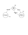
- FIG. 1 is a schematic block diagram showing a connection configuration in the power supply control system according to the first embodiment of the present invention.
- a camera 10A or a camera 10B is connected to the power supply control system 1 shown in FIG.
- the power supply control system 1 detects that the camera (imaging device) 10A is connected, it supplies power for driving the camera 10A.
- the camera 10A is supplied with power from the power supply control system 1 and complies with, for example, the “PoCL (Power-over-CAMERA Link) specification” (see Non-Patent Document 1).
- the “PoCL specification” defines a mode in which a camera connected to a grabber board (power control device) via a composite cable including a power supply line (electric wire) that supplies power is supplied with power from the power control device. .
- the camera 10 ⁇ / b> A is driven by power supplied from the power supply control system 1, converts a video signal indicating captured image information into an electrical signal, and outputs the electrical signal to the power supply control system 1.
- the video signal includes a digital signal, a clock signal synchronized with the digital signal, and the like.
- the power supply control system 1 detects that the camera 10B is connected, it does not supply power for driving the camera 10B.
- the camera 10 ⁇ / b> B is driven by power from another power supply facility (not shown), converts a video signal indicating captured image information into an electrical signal, and outputs the electrical signal to the power supply control system 1. Similar to the video signal output from the camera 10A, the video signal output from the camera 10B includes a digital signal and a clock signal synchronized with the digital signal.
- the specification of the camera 10B that does not receive power from the power supply control system 1 is not applied to the “PoCL specification”. In contrast to the “PoCL specification” of the camera 10A, the specification of the camera 10B is referred to as “non-PoCL specification”.
- the power supply control system 1 includes an active camera link cable 100 (active cable) and a power supply control device 200A.
- the active camera link cable 100 includes a composite cable 50F including electric wires 51 to 54 and an optical cable 55, and connector portions 30 and 40 provided at both ends of the composite cable 50F, respectively.
- the active camera link cable 100 is connected to either the camera 10 ⁇ / b> A or 10 ⁇ / b> B by the connector unit 30, and is connected to the power control apparatus 200 ⁇ / b> A by the connector unit 40.
- the connector units 30 and 40 include signal conversion units 30A and 40A that convert signals, respectively, and receive power supply from the power supply control device 200A.
- the power supply control device 200A supplies power through the first power supply system P1 and the second power supply system P2.
- the first power supply system P1 supplies power for driving the signal conversion units 30A and 40A of the active camera link cable 100 from the power supply control device 200A.
- the second power supply system P2 supplies power for driving the camera 10A from the power supply control device 200A to the camera 10A via the active camera link cable 100.
- the power supply control device 200A supplies the power for driving the signal conversion units 30A and 40A of the active camera link cable 100 via the first power supply system P1.
- the power supply control device 200A supplies power for driving the camera 10A via the second power supply system P2.
- the active camera link cable 100 can supply power from the power supply control device 200A to the camera 10A according to the “PoCL” specification.
- the active camera link cable 100 transmits a signal (video signal, clock signal) output from the camera 10A to the power supply control device 200A.
- the camera 10A may receive a control signal from the power supply control device 200A as an electrical signal and output a response signal corresponding to the received control signal as an electrical signal.
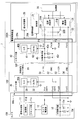
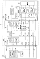
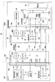
- FIG. 2 is a diagram illustrating a power supply control system that supplies power to the camera according to the first embodiment.
- the camera 10A connected to the power supply control system 1 will also be described.
- the camera 10A includes a second state instruction unit 15 that indicates that power supply is necessary.
- the power supply control system 1 supplies power from the power supply control device 200A connected to the camera 10A to the camera 10A that needs to be supplied with power.
- the determination as to whether or not power supply is required is made by detecting whether or not the camera 10A has the second state instruction unit 15 indicating that power supply is required.
- the power supply control system 1 includes the active camera link cable 100 and the power supply control device (including a grabber board) 200A.
- the active camera link cable 100 will be described.
- the active camera link cable 100 includes connector portions 30 and 40 and a composite cable 50F.
- the connector unit 30 includes a signal conversion unit 30A.
- the signal conversion unit 30 ⁇ / b> A includes an electro-optical conversion unit (E / O) 31 and a power supply unit (DC / DC) 32.
- the electro-optical conversion unit 31 converts an electric signal supplied from the camera 10A into an optical signal and outputs the optical signal.
- the power supply unit 32 converts the power supplied from the power supply control device 200A as the power supply system P1, and supplies the power to each unit such as the electro-optic conversion unit 31 in the signal conversion unit 30A.
- a power supply terminal of a power supply system P2 that is connected to the electric wire 53 and that supplies power to the camera 10A is provided.
- the connector part 30 has a shape that can be connected to the connection terminal part 10x included in the camera 10A.
- the connector unit 40 includes a signal conversion unit 40A and a first state instruction unit 45.
- the signal conversion unit 40A includes an opto-electric conversion unit (O / E) 41 and a power supply unit (DC / DC) 42.
- the photoelectric conversion unit 41 converts the optical signal supplied from the signal conversion unit 30A into an electrical signal and outputs the electrical signal.
- the power supply unit 42 converts the power supplied from the power supply control device 200A via the power supply system P1, and supplies it as power to each unit such as the photoelectric conversion unit 41 in the signal conversion unit 40A.
- the first state instruction unit 45 corresponds to a set of the electric wire 51 and the electric wire 52 in the power supply system P1 and includes a first circuit element connected between the electric wire 51 and the electric wire 52.
- the first circuit element includes, for example, a resistor 45r (for example, 10 k ⁇ (kiloohm)) and a capacitance 45c (for example, 57 ⁇ F (microfarad)) connected in parallel.
- a resistor 45r for example, 10 k ⁇ (kiloohm)
- a capacitance 45c for example, 57 ⁇ F (microfarad)
- the first state instruction unit 45 when a detection signal is supplied from the power supply control unit 21 of the power supply control device 200A via the electric wire 51, the voltage corresponding to the supplied detection signal is changed to the electric wire 51 and the electric wire 52. Occurs between.
- the detection signal is, for example, a weak current supplied from a constant current source 21Ac described later.
- the connector part 40 the power supply terminal of the power supply system P1 connected to the electric wire 51 and supplied with power to the signal conversion parts 30A and 40A, and the power supply of the power supply system P2 connected to the electric wire 53 and supplied with electric power to the camera 10A. And a terminal.
- the connector part 40 has a shape that can be connected to the connection terminal part 20x included in the power supply control device 200A.
- the composite cable 50F includes electric wires 51 to 54 and an optical cable 55.
- the electric wire 51 (first power line) is connected to a power terminal (for example, 1 pin) of the connector unit 40 and is a power supply line of the power system P1 in the active camera link cable 100.
- the electric wire 52 (first reference potential line) is connected to a power supply terminal (for example, 14 pins) of the connector section 40, and is a reference potential line (ground line) of the power supply system P1 in the active camera link cable 100.
- the electric wire 53 (first power line) is connected to the power terminals (for example, 26 pins) of the connector unit 30 and the connector unit 40, and is a power supply line of the power system P2 in the active camera link cable 100.
- the electric wire 54 (second reference potential line) is connected to the power supply terminals (for example, 13 pins) of the connector section 30 and the connector section 40, and is a reference potential line (ground line) of the power supply system P2 in the active camera link cable 100. is there.
- Each of the electric wires 51 to 54 is insulated from other signal lines, shield lines, and the like in the composite cable 50F.
- the optical cable 55 connects the electro-optic converter 31 in the signal converter 30A and the opto-electric converter 41 in the signal converter 40A.
- the number of cores of the optical cable 55 is one core or more.
- the active camera link cable 100 includes the connector unit 30 including the signal conversion unit 30A and the connector unit 40 including the signal conversion unit 40A.
- the connector unit 30 and the connector unit 40 are connected by the electric cables 51 to 54 included in the composite cable 50F and the optical cable 55.
- the electric wire 51 and the electric wire 53 are insulated from each other.
- Power is supplied to the active camera link cable 100 from a power supply control device 200 ⁇ / b> A connected via the connector unit 40.
- the signal conversion unit 30A uses the power supplied via the power supply system P1
- the signal conversion unit 30A changes the signal transmitted between the camera 10A and the power supply control device 200A from an electrical signal to an optical signal.
- the signal conversion unit 40A converts the converted optical signal into an electrical signal.
- the electric power supplied via the power supply system P1 is transmitted to the signal conversion units 30A and 40A by the set of the electric wire 51 and the electric wire 52.
- the set of the electric wire 53 and the electric wire 54 electric power supplied from the power supply control device 200A via the power supply system P2 is transmitted to the camera 10A.
- the optical cable 55 is provided between the signal conversion unit 30A and the signal conversion unit 40A, and transmits the optical signal converted by the signal conversion unit 30A.
- the first state indicating unit 45 connected to the electric wire 51 and the electric wire 52 is connected to the power supply control device 200A by the electric wire 51 and the electric wire 52, and a state where the power supply of the power supply system P1 is required. Indicates that The first state instruction unit 45 operates in the same manner as the second state instruction unit 15 included in the imaging device 10A in the power supply system P2.
- the power supply control device 200A includes a power supply control unit 20A, a power supply unit 28, a signal reception unit 29, and a connection terminal unit 20x.
- the power control unit 20A includes a power supply control unit 21, a connection switching unit 22, and a control unit 25.
- the power supply control unit 21 supplies the power supplied from the power supply unit 28 to the active camera link cable 100 by dividing the power supplied from the power supply unit 28 into the power supply system P1 and the power supply system P2 described above.
- the power supply control unit 21 detects the states of the power supply system P1 and the power supply system P2.
- the power supply control unit 21 controls the supply of power to the active camera link cable 100 according to the detected state.
- the power supply control unit 21 detects whether or not the first state instruction unit 45 of the power supply system P1 is connected to the electric wire 51, and based on the detection result, the power supply system for the signal conversion units 30A and 40A The supply of power by P1 is controlled. Further, the power supply control unit 21 detects whether or not the second state instruction unit 15 of the power supply system P2 is connected to the electric wire 53, and based on the detection result, the power supply system P2 uses the power supply system P2 for the imaging device 10A. Control power supply.
- the power supply control unit 21 includes power supply units 21A and 21B.
- the power supply unit 21A generates a detection signal (for example, a weak constant current) for detecting whether or not the first state instruction unit 45 of the power system P1 is connected to the electric wire 51 in the active camera link cable 100.
- the voltage is passed through the electric wire 51 and the terminal voltage of the output terminal connected to the electric wire 51 is detected.
- the power supply unit 21A determines the detected terminal voltage based on a predetermined threshold voltage, and detects whether or not the first state instruction unit 45 of the power system P1 is connected to the electric wire 51. Based on the detection result, the power supply unit 21A can determine whether or not the active camera link cable 100 is connected.
- the power supply unit 21 ⁇ / b> B sends a detection signal (for example, a weak constant current) for detecting whether or not the second state instruction unit 15 of the power supply system P ⁇ b> 2 is connected to the electric wire 53 to the electric wire 53.
- the terminal voltage of the output terminal connected to is detected.
- the power supply unit 21B determines the detected terminal voltage based on a predetermined threshold voltage, and detects whether or not the second state instruction unit 15 of the power system P2 is connected to the electric wire 53. Based on the detection result, the power supply unit 21B can determine whether or not the camera 10A is connected. Further, the power supply unit 21B detects a clock signal supplied from the camera 10A and detects the clock signal via the active camera link cable 100 to detect that the camera is connected.
- the connection switching unit 22 includes switches 22A and 22B.
- the switch 22 ⁇ / b> A switches between a conduction state and a cutoff state of the connection between the power supply control unit 21 and the electric wire 51 of the active camera link cable 100 under the control of the control unit 25.
- the switch 22 ⁇ / b> B switches between a connection state and a connection state between the power supply control unit 21 and the electric wire 53 of the active camera link cable 100 under the control of the control unit 25.
- the control unit 25 controls the power supply control unit 21 and the connection switching unit 22 according to the state detected by the power supply control unit 21.
- the power supply unit 28 supplies power for driving the camera 10 ⁇ / b> A and the signal conversion units 30 ⁇ / b> A and 40 ⁇ / b> A of the active camera link cable 100 as the power supply of the power supply system 1.
- the signal receiving unit 29 receives the signal converted in the connector unit 40.
- the connection terminal portion 20x has a shape that can be connected to the connector portion 40 of the active camera link cable 100, and a terminal corresponding to the connector 40 is provided.
- the power control unit 20A in the power control device 200A detects the first state instruction unit 45 connected to the electric wire 51, and supplies the power of the power system P1 to the signal conversion units 30A and 40A.
- the power supply control unit 20A detects the second state instruction unit 15 connected to the electric wire 53, and supplies the power of the power supply system P2 to the camera 10A.
- the camera 10A that receives the power supply from the power supply control apparatus 200A will be described.
- the camera 10A includes a signal generation unit 11, a camera power supply unit 12, a second state instruction unit 15, and a connection terminal unit 10x.
- the signal generation unit 11 includes an imaging unit 11d that captures an image of a subject and generates a video signal, and a clock unit 11c that generates a clock signal synchronized with a signal output from the imaging unit 11d.
- the camera power supply unit 12 converts power supplied to power supply terminals (for example, pin 1 and pin 26), and supplies the converted power as power to each unit in the camera 10A.
- the second state instruction unit 15 indicates that power supply is necessary.
- the second state instruction unit 15 includes a resistor 15r and a capacitance 15c.
- a resistor 15r for example, 10 k ⁇ (kiloohm)
- a capacitance 15c a capacitor, for example, 57 ⁇ F (microfarad)
- One end of the resistor 15r and the capacitance 15c is connected to a power supply terminal (pins 1 and 26), and the other end is connected to a power supply terminal (pins 13 and 14).
- a voltage corresponding to the supplied detection signal is It occurs between both terminals of the second state indicator 15.
- the detection signal is, for example, a weak current supplied from a current source 21Bc described later.
- a predetermined voltage (for example, + 12V) is applied to the power supply terminals (1 and 26 pins) in order for the camera 10A to receive power supply from the power supply terminals (1 and 26 pins).
- the connection terminal portion 10 x has a shape that can be connected to the connector portion 30 of the active camera link cable 100, and a terminal corresponding to the connector 30 is provided.
- the second state instruction unit 15 included in the camera 10 ⁇ / b> A and the first state instruction unit 45 included in the active camera cable 100 may have the same circuit configuration.
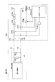
- FIG. 3 is a block diagram showing the configuration of the power supply unit 21A.
- the same components as those in FIGS. 1 and 2 are denoted by the same reference numerals.
- the power supply unit 21A includes a low-pass filter (LPF) 21Aa, a current limiting circuit (OCP) 21Ab, a current source 21Ac, a voltage detection circuit 21Ad, switches 21Ae, 21Af, and 21Ag, and a control logic unit 21Acont.
- the low-pass filter (LPF) 21 ⁇ / b> Aa is connected to the power supply unit 28 and reduces the noise component of the power supplied from the power supply unit 28.
- the current limiting circuit (OCP) 21Ab is connected to the low-pass filter (LPF) 21Aa and is a protection circuit that limits the current flowing through the power supply system P1 to a predetermined value or less. For example, the current limiting circuit 21Ab cuts off the flowing current by detecting heat generation of 360 mJ (millijoule).
- the current source 21Ac passes a weak constant current to the power supply system P1. For example, the value of the flowing current is 52 ⁇ A (microampere).
- the voltage detection circuit 21Ad detects a line voltage between the electric wires 51 and 52 of the power supply system P1, compares the detected line voltage with a predetermined threshold voltage (for example, 0.5 V), and detects the detected line voltage. It is determined whether the inter-voltage is greater than or equal to the threshold voltage.
- This threshold voltage can be an arbitrary value. For example, when the first state instruction unit 45 is detected by flowing a weak current from the power supply unit 21A, this threshold voltage is the voltage generated when the current source 21Ac flows the weak current to the first state instruction unit 45. A value that can detect a descent. When the power supply voltage supplied from the power supply unit 21A is monitored, this threshold voltage is set to a value that can detect a drop in the power supply voltage.
- the switch 21Ae cuts off the power supply to the electric wire 51 of the power supply system P1 under the control of the control logic unit 21Acont.
- the switch 21Af cuts off the supply of the reference potential (GND potential) to the electric wire 51 of the power supply system P1 under the control of the control logic unit 21Acont.
- the switch 21Ag cuts off the supply of the weak current from the current source 21Ac to the electric wire 51 of the power supply system P1 under the control of the control logic unit 21Acont.
- the control logic unit 21Acont detects the voltage drop detection signal output by the voltage detection circuit 21Ad.
- the control logic unit 21Acont controls the power supply unit 21A to a predetermined state based on the detected voltage drop detection signal.
- the control logic unit 21Acont detects a voltage drop detection signal from the voltage detection circuit 21Ad after applying a voltage to the electric wire 51 of the power supply system P1
- the control logic unit 21Acon determines that it is in an abnormal state, turns off the switch 21Ae, and activates the switch 21Ae.
- the connection state of the camera link cable 100 is determined again.
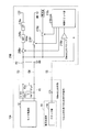
- FIG. 4 is a block diagram showing a configuration of the power supply unit 21B.
- the same components as those in FIGS. 1 and 2 are denoted by the same reference numerals.
- the power supply unit 21B includes a low-pass filter (LPF) 21Ba, a current limiting circuit (OCP) 21Bb, a current source 21Bc, a voltage detection circuit 21Bd, switches 21Be, 21Bf, and 21Bg, and a control logic unit 21Bcont.
- the low-pass filter (LPF) 21Ba is connected to the power supply unit 28 and reduces the noise component of the power supply supplied from the power supply unit 28.
- the current limiting circuit (OCP) 21Bb is connected to the low-pass filter (LPF) 21Ba and is a protection circuit that limits the current flowing through the power supply system P2 to a predetermined value or less. For example, when a heat generation of 360 mJ (millijoule) is detected, the current that flows is cut off.
- the current source 21Bc passes a weak constant current to the power supply system P2. For example, the value of the flowing current is 52 ⁇ A (microampere).
- the voltage detection circuit 21Bd detects a line voltage between the electric wire 53 and the electric wire 54 of the power supply system P2, compares the detected line voltage with a predetermined threshold voltage (for example, 0.5 V), and detects the detected line voltage. It is determined whether the inter-voltage is greater than or equal to the threshold voltage.
- the threshold voltage can be an arbitrary value. For example, when the second state instruction unit 15 is detected by flowing a weak current from the power supply unit 21B, the threshold voltage is a voltage drop caused by the current source 21Bc flowing the weak current to the second state instruction unit 15. Is a value that can be detected. When the power supply voltage supplied from the power supply unit 21B is monitored, the threshold voltage is set to a value that can detect a drop in the power supply voltage.
- the switch 21Be cuts off the power supply to the electric wire 53 of the power supply system P2 under the control of the control logic unit 21Bcont.
- the switch 21Bf blocks the supply of the reference potential to the electric wire 53 of the power supply system P2 under the control of the control logic unit 21Bcont.
- the switch 21Bg blocks the supply of the weak current from the current source 21Bc to the electric wire 53 of the power supply system P2 under the control of the control logic unit 21Bcont.
- the control logic unit 21Bcont detects the voltage drop detection signal output by the voltage detection circuit 21Bd and the clock signal supplied from the camera 10A via the optical cable 55.
- the control logic unit 21Bcont controls the power supply unit 21B to a predetermined state based on the detected voltage drop detection signal and the clock signal state.
- the control logic unit 21Bcont detects a voltage drop detection signal from the voltage detection circuit 21Bd after applying a voltage to the electric wire 53 of the power supply system P2
- the control logic unit 21Bcont determines that it is in an abnormal state, turns off the switch 21Be, 21Bf is made conductive, and the voltage applied to the electric wire 53 of the power supply system P2 is set to the reference potential (GND potential).
- the control logic unit 21Bcont determines that the state is abnormal and determines the connection state of the camera 10A again. Further, the control logic unit 21Bcont outputs the detected result to the outside.
- a predetermined time for example, 100 ms (milliseconds)
- the active camera link cable 100 shown in FIG. 1 to FIG. 4 converts the signal from the camera 10A or 10B by the power supplied from the power supply system P1 and transmits it in the signal converters 30A and 40A.
- the power supplied from the power supply system P2 is supplied to the camera 10A.
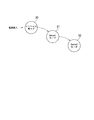
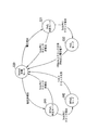
- FIG. 5 is a state transition diagram showing a sequence for controlling power supply in the power supply system.
- the power supply control unit 20A performs control according to, for example, a control sequence shown in FIG. (State S0): “Initial mode” indicates a control state in which the control unit 25 performs initialization processing (initial processing) after the power source of the power supply control device 200A is turned on. In this “initial mode”, the control unit 25 transitions the control state to the next (state S1) after completing the initialization process.
- State S1): “Sense 1 mode” indicates a control state in which connection of the active camera link cable 100 is detected.
- the control unit 25 detects whether or not the active camera link cable 100 is connected, and after completing the detection, shifts the control state to the next (state S2).
- state S2 “Sense 2 mode” indicates a control state in which it is detected whether or not the connected camera has the “PoCL” specification.
- the control unit 25 detects whether or not the connected camera has the “PoCL” specification.
- the control unit 25 detects the specifications of the connected composite cable and the camera by the determination process performed by switching the order of the two-stage control states, and controls the supply of each power according to the detection result. To do.
- FIG. 6 is a state transition diagram in the “Sense 1 mode”.
- the sequence of “Sense 1 mode” shown in FIG. 6 corresponds to (State S 1): “Sense 1 mode” in FIG. (State S10): “Sense 1 initial mode” indicates an initial state in “Sense 1 mode” (FIG. 5).
- the control state which determines whether the electric power of the power supply system P1 is supplied with respect to the signal conversion parts 30A and 40A of the active camera link cable 100 is shown.
- the control unit 25 controls the power supply unit 21A of the power supply control unit 21 as shown below, and the power supply system P1 controls the signal conversion units 30A and 40A from the power supply unit 21A. It is determined whether to supply power.
- control unit 25 controls the connection switching unit 22 to turn on the switch 22A and cut off the switch 22B. Further, the control unit 25 causes the power supply control unit 21 to determine whether or not power supply from the power supply control unit 21 is necessary. In the power supply control unit 21, the power supply unit 21A detects whether or not the active camera link cable 100 is connected to the power control device 200A.
- the control logic unit 21Acont turns off the switches 21Ae and 21Af, turns on the switch 21Ag, and flows a weak constant current from the current source 21Ac to the electric wire 51 in the power supply system P1.
- the active camera link cable 100 includes the first state instruction unit 45, so that a voltage drop is generated between the electric wire 51 and the electric wire 52. A voltage is generated.
- the voltage detection circuit 21Ad detects a line voltage (power supply system P1) between the electric wires 51 and 52, and compares the detected line voltage with a predetermined threshold voltage (for example, 0.5 V), It is detected whether or not the detected line voltage is equal to or higher than a threshold voltage.
- a predetermined threshold voltage for example, 0.5 V
- the control logic unit 21Acont sets the first between the electric wire 51 and the electric wire 52. It is determined that the state instructing unit 45 is connected, that is, the active camera link cable 100 is connected. Based on the determination result, the control unit 25 shifts the control state to the next (state S11).
- the camera link cable 100M (FIG. 9) is connected to the power supply control apparatus 200A, the camera link cable 100M does not include the first state instruction unit 45. No voltage due to a voltage drop is generated between the power line 52 and the electric wire 52. Even if the voltage detection circuit 21Ad detects the line voltage (power supply system P1) between the electric wire 51 and the electric wire 52, the voltage detection circuit 21Ad cannot detect a voltage equal to or higher than a threshold voltage (for example, 0.5 V).
- a threshold voltage for example, 0.5 V
- the control logic unit 21Acont When it is detected from the comparison result by the voltage detection circuit 21Ad that the line voltage (power supply system P1) is not equal to or higher than the threshold voltage, the control logic unit 21Acont has a first state between the wire 51 and the wire 52. It is determined that the instruction unit 45 is not connected, that is, the active camera link cable 100 is not connected, and the camera link cable 100M may be connected. Based on the determination result, the control unit 25 shifts the control state to (state S12).
- the control unit 25 controls the power supply unit 21A of the power supply control unit 21 to supply power to the active camera link cable 100 from the power supply unit 21A.
- the control logic unit 21Acont turns off the switches 21Af and 21Ag, turns on the switch 21Ae, and puts the voltage from the power supply into the power supply terminal.
- the electric potential of the electric wire 51 with respect to the electric potential (reference electric potential) of the electric wire 52 can be set to a predetermined voltage necessary for driving the active camera link cable 100.
- the voltage detection circuit 21Ad compares the line voltage between the electric wires 51 and 52 of the power supply system P1 with a predetermined threshold voltage to detect whether the line voltage is equal to or higher than the threshold voltage.
- the voltage detection circuit 21Ad detects that the detected line voltage has dropped below the threshold voltage, and then the state where the detected line voltage has dropped below the threshold voltage is a predetermined time (for example, 20 ms (milliseconds)). Second)) When it is detected that the current continues, the control logic unit 21Acont determines that the state in which the line voltage between the electric wire 51 and the electric wire 52 has abnormally decreased continues. Thereby, the control part 25 determines with the power supply control part 21 having detected the abnormal state, and changes a control state according to the determination result (state S10). However, in the later-described (state S20), when the switch 22A in the connection switching unit 22 is turned off, the voltage detected by the voltage detection circuit 21Ad is the voltage output by the power supply unit 21A.
- State S12 “Camera link cable mode” indicates a control state in which power is not supplied to the connected composite cable, that is, it is determined that the active cable 100M (FIG. 9) is connected. Indicates the control state.
- the control unit 25 controls the power supply unit 21A of the power supply control unit 21 to cut off the supply of power for driving the signal conversion unit from the power supply unit 21A and The potential 51 is set to the reference potential.
- the control logic unit 21Acont turns off the switches 21Ae and 21Ag, turns on the switch 21Af, and sets the potential of the electric wire 51 to the reference potential (GND potential). Thereby, the electric potential of the electric wire 51 can be made the electric potential of the electric wire 52 (reference potential).
- the voltage detection circuit 21Ad compares the line voltage between the electric wires 51 and 52 of the power supply system P1 with a predetermined threshold voltage, and determines whether or not the detected line voltage is equal to or higher than the threshold voltage. To detect. The voltage detection circuit 21Ad detects that the detected line voltage is lower than a predetermined threshold voltage.
- control unit 25 controls the power supply unit 21A of the power supply control unit 21 to set the potential output from the power supply unit 21A to the reference potential. In this way, after determining that the state is either (state S11) or (state S12), the control unit 25 shifts the control state to the next (state S2) (FIG. 5).
- FIG. 7 is a state transition diagram in the “Sense 2 mode”.
- the sequence of “Sense 2 mode” shown in FIG. 7 corresponds to (state S2): “Sense 2 mode” in FIG. (State S20): “Sense2 initial mode” indicates an initial state in “Sense2 mode” (FIG. 5).
- the control state which determines whether the electric power of the power supply system P2 is supplied with respect to a camera is shown.
- the control unit 25 controls the power supply unit 21B of the power supply control unit 21 to supply power from the power supply system P2 to the camera from the power supply unit 21B as follows. Determine whether or not. First, the control unit 25 controls the connection switching unit 22 to turn on the switch 22B and shut off the switch 22A.
- control unit 25 causes the power supply control unit 21 to determine whether or not power supply from the power supply control unit 21 is necessary.
- the power supply unit 21 ⁇ / b> B detects whether the camera 10 ⁇ / b> A is connected to the power supply control system 1.
- the power supply unit 21B shifts the control state to (state S31), and detects that the camera 10B is connected ( The control state is shifted to the state S41).
- the control logic unit 21Bcont turns off the switches 21Be and 21Bf, turns on the switch 21Bg, and allows a weak constant current to flow from the current source 21Bc to the electric wire 53 in the power supply system P2.
- the control logic unit 21Bcont turns off the switches 21Be and 21Bf, turns on the switch 21Bg, and allows a weak constant current to flow from the current source 21Bc to the electric wire 53 in the power supply system P2.
- a voltage due to a voltage drop is generated between the electric wire 53 and the electric wire 54 because the camera 10 ⁇ / b> A includes the second state instruction unit 15.
- the voltage detection circuit 21Bd compares the line voltage (power supply system P2) between the electric wires 53 and 54 with a predetermined threshold voltage (for example, 0.5 V), and the detected line voltage is equal to or higher than the threshold voltage. It is detected whether it is.
- a predetermined threshold voltage for example, 0.5 V
- the control logic unit 21Bcont is connected between the electric wire 53 and the electric wire 54. 2, it is determined that there is a possibility that the camera 10 ⁇ / b> A is connected.
- the control unit 25 changes the control state to (state S31) according to the determination result.
- the control logic unit 21Bcont has the second state between the wire 53 and the wire 54. It is determined that the instruction unit 15 is not connected, that is, the camera 10A is not connected, and that the camera 10B may be connected.
- the control unit 25 changes the control state to (state S41) based on the determination result.
- “PoCL determination mode” indicates a control state in which the power of the power supply system P2 is supplied to the camera 10A and the clock from the camera 10A is detected.
- the control unit 25 controls the connection switching unit 22 to make the switches 22A and 22B conductive, controls the power supply unit 21B of the power supply control unit 21, and controls the camera 10A from the power supply unit 21B. Is supplied with power from the power supply system P2. Then, the control unit 25 causes the power supply unit 21B of the power supply control unit 21 to detect the clock transmitted from the camera 10A.
- the control logic unit 21Bcont puts the switches 21Bf and 21Bg into a cut-off state, puts the switch 21Be into a conductive state, and puts the voltage from the power supply into the electric wire 53. Thereby, the electric potential of the electric wire 53 with respect to the electric potential (reference potential) of the electric wire 54 can be set to a predetermined voltage necessary for driving the camera 10A.
- the control logic unit 21Bcont applies a predetermined voltage between the electric wire 53 and the electric wire 54 after the predetermined voltage is applied between the electric wire 53 and the electric wire 54, and then the clock from the camera 10A is within a predetermined time (for example, 3 s (seconds)).
- control logic unit 21Bcont When the control logic unit 21Bcont cannot detect the clock from the camera 10A within a predetermined time after applying a predetermined voltage between the electric wire 53 and the electric wire 54, the control logic unit 21Bcont shuts off the switch 21e. In this state, application of voltage to the power supply terminals connected to the electric wires 53 and 54 is stopped. In accordance with the detection result, the control unit 25 makes a transition to (state S20) and repeatedly performs the detection process.
- control logic unit 21Bcont determines that the camera 10A is connected when the clock from the camera 10A can be detected within a predetermined time after applying the voltage.
- the control unit 25 makes a transition to (state S32) according to the determination result.
- the control unit 25 controls the power supply unit 21B of the power supply control unit 21 to supply the power of the power system P2 from the power supply unit 21B to the camera 10A.
- the control unit 25 detects in advance whether or not the clock sent from the camera 10A has been lost by the power supply unit 21B and the line voltage between the electric wire 53 and the electric wire 54 is determined in advance for abnormality detection. Whether or not the threshold voltage is lowered is detected.
- the control state is changed to (State S20). Transition.
- the control logic unit 21Bcont continues to determine whether or not the clock from the camera 10A is lost for a predetermined time (for example, 100 ms (milliseconds)) after the clock from the camera 10A is lost. To do.
- the control logic unit 21Bcont detects a missing clock from the camera 10A and continues for a predetermined time or more, and detects a missing clock from the camera 10A, the control logic unit 21Bcont turns off the switch 21e, Application of the line voltage between the electric wire 53 and the electric wire 54 is stopped.
- the voltage detection circuit 21Bd detects a line voltage (power supply system P2) between the electric wire 53 and the electric wire 54.
- the voltage detection circuit 21Bd continues for a predetermined time (for example, 20 ms (milliseconds)) or more after the line voltage between the electric wires 53 and 54 drops below a predetermined threshold voltage.
- a predetermined time for example, 20 ms (milliseconds)
- the switch 21e is turned off, and the application of the voltage to the power supply terminal connected to the electric wire 53 and the electric wire 54 is stopped.
- the control unit 25 shifts the control state to (state S20).
- Non-PoCL determination mode indicates a control state in which power is not supplied to the connected camera (camera 10B) and a clock from the camera is detected.
- the connected camera is referred to as a camera 10B.
- the control unit 25 controls the connection switching unit 22 to make the switches 22A and 22B conductive, controls the power supply unit 21B of the power supply control unit 21, and controls the power supply unit 21B to the camera. The supply of power from the power supply system P2 to 10B is cut off. Then, the control unit 25 causes the power supply unit 21B of the power supply control unit 21 to detect a clock sent from the camera 10B.
- the control logic unit 21Bcont sets the switches 21Be and 21Bg in the cut-off state and the switch 21Bf in the conductive state to set the potential of the electric wire 53 to the reference potential. Thereby, the electric potential of the electric wire 53 can be made the electric potential of the electric wire 54 (reference potential).
- the control logic unit 21Bcont determines whether or not the clock from the camera 10B can be detected within a predetermined time (for example, 3 seconds (s)). After starting the detection, the control logic unit 21Bcont interrupts the clock detection when the clock from the camera 10B cannot be detected within a predetermined time. In accordance with the detection result, the control unit 25 makes a transition to (state S20) and repeatedly performs the detection process.
- control logic unit 21Bcont determines that the camera 10B is connected when the clock from the camera 10B can be detected within a predetermined time after starting the detection.
- the control unit 25 makes a transition to (state S42) according to the determination result.
- Non-PoCL mode indicates a control state in which a signal from the camera 10B is transmitted.
- the control unit 25 controls the power supply unit 21B of the power supply control unit 21 so that power from the power supply system P2 is not supplied from the power supply unit 21B to the camera 10B.
- the control unit 25 detects whether or not the clock sent from the camera 10B is lost by the power supply unit 21B for abnormality detection. Transition the control state.
- the control logic unit 21Bcont detects whether or not the clock from the camera 10B is lost continuously for a predetermined time (for example, 1 s (seconds)) after detecting that the clock from the camera 10B has been lost. Determine. When the control logic unit 21Bcont detects that the clock from the camera 10B has been lost, and continuously detects a missing clock from the camera 10B for a predetermined time (for example, 1 s (seconds)). It is determined that there is an abnormality in the transmission from the camera 10B. When it is detected that the state is the above state, the control unit 25 shifts the control state to (state S20).
- a predetermined time for example, 1 s (seconds)
- the power supply control unit 21 in the power supply control device 200A detects the second state instruction unit 15 in the camera 10A via the electric wires 53 and 54 in the active camera link cable 100. To do. Further, the power supply control unit 21 detects the first state instruction unit 45 in the active camera link cable 100. Since the camera 10A, the active camera link cable 100, and the power supply control device 200A are connected, the power supply control unit 21 is provided with a second state instruction unit 15 and a first state instruction unit 45. Can be detected. Thereby, the power supply control device 200A can supply power to each of the camera 10A and the active camera link cable 100.
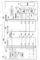
- FIG. 8 is a diagram illustrating a configuration in which the camera 10B and the active camera link cable 100 are connected to the power supply control device 200A.
- the same components as those in FIGS. 1 and 2 are denoted by the same reference numerals.
- the difference from FIG. 2 is that the camera specification is a non-PoCL specification.
- the power supply unit 21B in the power supply control unit 21 does not need to supply power from the power supply system P2 to the camera 10B because the camera 10B has the non-PoCL specification.
- the power supply unit 21A in the power supply control unit 21 supplies power to the signal conversion units 30A and 40A of the active camera link cable 100 by detecting the first state instruction unit 45 in the connector unit 40. To do.
- the power supply unit 21B in the power supply control unit 21 cannot detect the second state instruction unit 15 in the camera 10B. Thereby, the power supply unit 21B does not supply power to the camera 10B.
- the power supply unit 21B detects a clock signal supplied from the camera 10B via the active camera link cable 100 and detects that the camera is connected.
- the control unit 25 can select power supply according to each specification by individually determining the camera and the composite cable.
- the power supply control device 200A can supply the power of the power supply system P1 to the signal processing units 30A and 40A of the active camera link cable 100. Then, the power supply control device 200A can receive a signal from the camera 10B.
- FIG. 9 is a diagram illustrating a configuration in which the camera 10A and the camera link cable 100M are connected to the power supply control device 200A.
- the same components as those in FIG. 2 is that a camera link cable 100M is provided instead of the active camera link cable 100.
- the camera link cable 100M includes connector portions 30M and 40M and a composite cable 50M.
- the composite cable 50M includes electric wires 51 to 54 and an electric wire 56.
- the electric wire 51 is connected to the power supply terminals (for example, 1 pin) of the connector unit 30M and the connector unit 40M, and is a power supply line in the camera link cable 100M.
- the electric wire 52 is connected to the power supply terminals (for example, 14 pins) of the connector unit 30M and the connector unit 40M, and is a reference potential line (ground line) in the camera link cable 100M.
- the electric wire 53 is connected to the power supply terminals (for example, 26 pins) of the connector unit 30M and the connector unit 40M, and is a power supply line in the camera link cable 100M.
- the electric wire 54 is connected to the power supply terminals (for example, 13 pins) of the connector portion 30M and the connector portion 40M, and is a reference potential line (ground line) in the camera link cable 100M.
- Each of the electric wires 51 to 54 is insulated from other signal lines, shield lines, and the like in the composite cable 50M.
- the electric wire 56 is a signal line that is connected to the signal terminals of the connector unit 30M and the connector unit 40M and transmits a signal in the camera link cable 100M. Further, each of the electric wires 51 to 54 and 56 is insulated from other signal lines, shield lines, etc. in the composite cable 50M.
- the camera link cable 100M is formed of electric wires as described above, and does not include an active circuit that performs signal conversion inside. That is, the camera link cable 100M does not require power supply unlike the active camera link cable 100 of FIG.
- the power supply terminals 1 and 26 and the power supply terminals 13 and 14 are short-circuited inside the camera 10A. Further, all the power terminals of the camera 10A are connected to the power control apparatus 200A by the camera link cable 100M. For this reason, it is necessary to control the power supply control unit 21 so that different potentials are not applied to the 1st and 26th power terminals and the 13th and 14th power terminals.
- the power supply unit 21A of the power supply control unit 21 detects the state detection unit 15 of the camera 10A instead of the state determination unit 45 in the determination in “state S1” in FIG. 5, as if the active camera link cable 100 is Recognize that it is connected. Further, the power supply unit 21B of the power supply control unit 21 detects the state detection unit 15 of the camera 10A in the determination in the “state S2” of FIG. As a result, the power supply control unit 21 recognizes the same configuration as the configuration shown in FIG. In the configuration shown in FIG. 9, the power supply control unit 21 applies the voltage supplied from the power supply 28 to the electric wires 51 and 53.
- the power supply control unit 21 can supply the power required for the camera 10B. . Further, the power supply unit 21B detects a clock signal supplied from the camera 10A and detects the clock signal via the camera link cable 100M to detect that the camera is connected.
- the power supply control unit 21 replaces the first state instruction unit 45 with the second state in the camera 10A.
- Power can be supplied by detecting the instruction unit 15 and determining that it is necessary to supply power.
- the control unit 25 enables the power supply to the camera 10A by setting the switch 22 and the switch 24 in a short-circuit state.
- a predetermined potential required for driving the camera 10A can be applied to the electric wire 51 and the electric wire 53.
- the determination by the power supply control unit 21 can be performed by the same sequence as that of the configuration shown in FIG. However, when applied to the configuration shown in FIG. 9, the power voltages supplied as the power supply systems 1 and 2 are the same voltage.
- FIG. 10 is a diagram illustrating a configuration in which the camera 10B and the camera link cable 100M are connected to the power supply control device 200A.
- the same components as those in FIGS. 2, 8, and 9 are denoted by the same reference numerals.
- the difference from FIG. 2 is that the camera specification is a non-PoCL specification, and the camera link cable 100M is used instead of the active camera link cable 100.
- the power supply control unit 21 since the power supply control unit 21 detects that the specification of the camera 10B is a non-PoCL specification, it does not supply the power of the power supply system P2 to the camera 10B.
- the power supply control unit 21 does not include the first state instruction unit 45 in the camera link cable 100M and is grounded in the camera 10B.
- the power supply of the power supply system P1 is not determined.
- the control unit 25 makes both the switch 22 and the switch 24 conductive, but the applied potential is a reference potential.
- any potential of the electric wires 51 to 54 can be set to the same reference potential (GND).
- the power supply unit 21B detects a clock signal supplied from the camera 10B and connected to the camera via the camera link cable 100M to detect that the camera is connected.
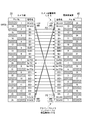
- FIG. 11 is a diagram showing the connection of the connector portion in the power supply control system shown in the present embodiment.
- the terminals of the connector section 40 of the active camera link cable 100 shown in FIG. 1 are assigned with terminals of a power supply system provided in two systems.
- One of the two power supply systems is a power supply system P1 that supplies power to the signal conversion units 30A and 40A of the active camera link cable 100, and the other is a power supply system P2 that supplies power to the camera 10A.
- the power supply terminals of the power supply system P1 that supplies power to the signal conversion units 30A and 40A are, for example, 1 pin and 14 pins, and the power supply terminals of the power supply system P2 that supplies power to the camera 10A are, for example, 13 pins and 26 pins. is there.
- the signal conversion unit from the power supply control device 200A is assigned to the connector unit 40 by assigning the power supply terminals for supplying the power of the power system P1 to the signal conversion units 30A and 40A of the active camera link cable 100
- the power supply system P1 can supply power to 30A and 40A.
- the power supply terminal of the power supply system P2 that supplies power to the camera 10A is assigned to the terminal of the connector portion 30 of the active camera link cable 100. As described above, by assigning only the power supply terminal that supplies the power of the power supply system P2 to the camera 10A in the connector unit 30, the power supply system that supplies power to the active camera link cable 100 is changed to the power supply system of the camera 10A or 10B. It is possible to insulate so as not to connect.
- the connector portions 30 and 40 of the active camera link cable 100 have all 26-pin terminals that can be electrically connected, and are connected to the camera 10A or 10B and the power supply control device 200A, respectively.
- the active camera link cable 100 is supplied with power from the power supply control device 200 ⁇ / b> A by a power supply terminal provided in the connector unit 40.
- a power supply terminal provided in the connector unit 40.
- two terminals (1 pin and 14 pin) are allocated as terminals dedicated to the power supply system P2 that supplies power to the camera 10A, and the electric wire 53 is connected to 1 pin and the electric wire 54 is connected to 14 pin.
- a predetermined voltage based on the potential (reference potential (GND potential)) of the electric wire 54 (pin 14) is applied to the electric wire 53 (pin 1).
- the voltage may be, for example, + 12V.
- the other two ground terminals (pin 13 and pin 26) are assigned as dedicated power supply terminals for supplying power to the active camera link cable 100, and a predetermined potential with reference to the potential of 13 pins (reference potential (GND potential)). Is applied to pin 26.
- the voltage may be, for example, + 12V.
- terminals for transmitting video signals, clock signals, control signals, and the like are assigned to all 26-pin connection terminals as in the power supply system.
- “+” and “ ⁇ ” shown in the signal names of the respective terminals indicate paired signals.
- “+/ ⁇ ” is added to the signal name of each terminal.
- “D0 +/ ⁇ ” to “D3 +/ ⁇ ” correspond to the four data signals (X0 to X3)
- “CLK0 +/ ⁇ ” corresponds to the clock signal (CLKX)
- ⁇ To “CC4 +/ ⁇ ” correspond to the camera control signal (Camera Control 1 to 4), and “SerTC +/ ⁇ ” and “SerTFG +/ ⁇ ” correspond to the control signal (SerTC, SerTFG).
- the above signals are assigned pin numbers 2 to 12 and 15 to 25 on the camera 10A side and the power supply control device 200 side.
- the signal terminals in the connector portions 30 and 40 are assigned to pin numbers corresponding to the respective signals, as shown in the figure.
- the power supply control device 200A determines the required power supply condition without being affected by the combination of the camera specification and the cable specification, and is required. It can be controlled to supply power.
- FIG. 12 is a diagram showing a power supply control system in the present embodiment.
- the same components as those in FIG. A power supply control system 1B shown in FIG. 12 includes a power supply control apparatus 200B instead of the power supply control apparatus 200A shown in the first embodiment.
- the power supply control device 200B includes a power supply control unit 20B, a power supply unit 28, a signal reception unit 29, and a connection terminal unit 20x.
- the power control unit 20B includes a power supply control unit 21C, a connection switching unit 22, and a control unit 25.
- the power supply control unit 21 ⁇ / b> C outputs the power supplied from the power supply unit 28 to the active camera link cable 100 using the power supply unit 28 as a power supply.
- the power supply control unit 21C detects the states of the power supply system P1 and the power supply system P2.
- the power supply control unit 21 controls the supply of power to the active camera link cable 100 according to the detected state.
- the power supply control unit 21C sends a detection signal (for example, a weak constant current) for detecting whether or not the first state instruction unit 45 of the power system P1 is connected to the electric wire 51, and detects the terminal voltage of the same terminal Then, it is determined whether or not the active camera link cable 100 is connected. Further, the power supply control unit 21C sends a detection signal (for example, a weak constant current) that detects that the camera 10A is connected, detects the terminal voltage of the same terminal, and the camera 10A is connected. It is determined whether or not.
- a detection signal for example, a weak constant current
- the power supply control unit 21C detects whether or not the first state instruction unit 45 of the power supply system P1 is connected to the electric wires 51 and 52, and based on the detection result, the power supply system P1 uses the signal conversion unit. Controls the supply of power to 30A and 40A. Further, the power supply control unit 21C detects whether or not the second state instruction unit 15 of the power supply system P2 is connected to the electric wire 53 and the electric wire 54, and based on the detection result, the power supply system P2 The power supply to the imaging device 10A is controlled.
- FIG. 13 is a block diagram showing the configuration of the power supply control unit 21C.
- 1, 2, 3, and 4 are denoted by the same reference numerals, the power supply units 21 ⁇ / b> A and 21 ⁇ / b> B described above are connected to the power supply control unit 21 ⁇ / b> C, and the control logic units 21 ⁇ / b> Acont and 21 ⁇ / b> Bcont are controlled to the control logic unit 21 ⁇ / b> Ccont
- the power supply control unit 21C includes a low-pass filter (LPF) 21Aa, a current limiting circuit (OCP) 21Ab, a current source 21Ac, a voltage detection circuit 21Ad, switches 21Ae, 21Af, 21Ag, a low-pass filter (LPF) 21Ba, and a current limiting circuit (OCP).
- LPF low-pass filter
- OCP current limiting circuit
- control logic unit 21Ccont has the function of the control logic unit 21Acont and the function of the control logic unit 21Bcont. That is, control in the power supply control unit 21C can be performed by the integrated control logic unit 21Ccont. Accordingly, the control logic unit 21Ccont can be configured without being separated into the control logic units 21Acont and 21Bcont, and a simple configuration can be achieved. Also in this embodiment, the present invention can be applied to the different modes shown in FIGS. 8 to 10 in the first embodiment.
- the power supply control device 200B shown in the present embodiment is necessary without being affected by the combination of the camera specification and the composite cable specification.
- the power supply can be controlled by determining the condition.
- the power supply control system 1 (1B) is connected to the camera 10A connected via the active camera link cable 100 and the power supply control device 200A with respect to the active camera link cable 100. (200B) can supply power.
- the active camera link cable 100 includes a connector unit 30 including a signal conversion unit 30A and a connector unit 40 including a signal conversion unit 40A. And the connector portion 40 are connected to each other by an electric cable 51 and an electric cable 53 that are insulated from each other, and an optical cable 55.
- the electric wire 51 transmits the supplied electric power to the signal conversion unit 30A
- the electric wire 53 transmits the electric power supplied from the power supply control device 200A to the camera 10A
- the optical cable 55 is the light converted by the signal conversion unit 30A. Transmit the signal.
- Such an active camera link cable 100 is supplied with power from the power supply control device 200A connected by the connector unit 40, and the signal conversion unit 30A transmits between the camera 10A and the power supply control device 200A by the supplied power.
- the converted signal is converted into an optical signal, and the signal conversion unit 40A converts the converted optical signal.
- indication part 45 with which either the connector part 30 or the connector part 40 is provided shows the state by which the electric wire 51 is connected to 200 A of power supply control apparatuses.
- the power control unit 20A in the power control apparatus 200A that supplies power to the camera 10A supplies power to the signal conversion units 30A and 40A based on the state indicated by the first state instruction unit 45.
- the power supply control system 1 can control the supply of electric power required for signal conversion in the active camera link cable 100. That is, the power supply control unit 20A can control the supply of power to the signal conversion units 30A and 40A based on the state indicated by the first state instruction unit 45.
- the first state instruction unit 45 of the power supply system P1 in the present embodiment is provided corresponding to the electric wire 51, and the first circuit element (resistor 45r) is connected between the electric wire 51 and the electric wire 52.
- the power supply control unit 20A detects the first circuit element (resistor 45r) as the first state instruction unit 45 of the power supply system P1, and supplies power to the signal conversion units 30A and 40A. Thereby, the power supply control unit 20A controls the power supplied to the signal conversion units 30A and 40A according to the detection result of the first circuit element (resistor 45r) of the first state instruction unit 45 of the power supply system P1. be able to.
- the power supply control unit 20A in this embodiment detects the second circuit element (resistor 15r) connected between the electric wire 53 and the electric wire 54 as the second state instruction unit 15 of the power supply system P2. Then, power is supplied to the camera 10A. Thereby, the power supply control unit 20A can control the supply of power to the camera 10A.
- the power supply control unit 21 determines whether or not the signal conversion unit 21 is based on the detection result of whether or not the first state instruction unit 45 of the power supply system P1 is connected to the electric wire 51.
- the power of 30A and 40A is supplied, and the power is supplied to the camera 10A based on the detection result of whether or not the second state instruction unit 15 of the power supply system P2 is connected to the electric wire 53.
- the power supply control unit 20A can control the supply of power to the signal conversion units 30A and 40A and the supply of power to the camera 10A.
- connection switching unit 22 connects each of the electric wire 51 and the electric wire 53 to the power supply control unit 21.
- the control unit 25 controls the connection switching unit 22 according to the detection result of the first state instruction unit 45 of the power system P1 and the detection result of the second state instruction unit 15 of the power system P2.
- the power supply control unit 20A causes the electric wire 51 to the power supply control unit 21 based on the detection result of the first state instruction unit 45 of the power supply system P1 and the detection result of the second state instruction unit 15 of P2.
- connection of the electric wire 53 can be switched by the connection switching part 22, and supply of the electric power with respect to the signal conversion parts 30A and 40A and the supply of the electric power with respect to the camera 10A can be controlled.
- the power supply control unit 21 in this embodiment can independently control the power supply unit 21A that supplies power to the signal conversion units 30A and 40A and the power supply unit 21B that supplies power to the camera 10A. .
- the power supply control unit 21 in the present embodiment first detects the presence / absence of the first state instruction unit 45 of the power supply system P1, and then continues to detect the presence / absence of the second state instruction unit 15 of the power supply system P2. Perform detection.
- the power supply control unit 21 supplies power to the signal conversion units 30A and 40A according to the detection result of the first state instruction unit 45 of the power system P1, and the detection result of the second state instruction unit 15 of the power system P2 In response to this, power is supplied to the camera 10A.
- the power supply control part 21 after activating the active camera link cable 100 previously, it can control to supply the electric power with respect to camera 10A.
- a power supply terminal for supplying power to the camera 10A is connected to the electric wire 53.
- a power supply terminal to which power for the active camera link cable 100 is supplied is connected to the electric wire 51, and a power supply terminal to which power for the camera 10 ⁇ / b> A is supplied is connected to the electric wire 53.
- the connector part 40 in this embodiment can be connected to the connection terminal part with which the power supply control apparatus 200A is provided.
- the active camera link cable 100 in the present embodiment can convert the video signal supplied from the camera 10A into an optical signal and transmit it to the power supply control device 200A.
- the connector unit 40 has been shown to include the first state instruction unit 45, the first state instruction unit 45 may be provided in one of the connector units 30 and 40. Further, the first state instruction unit 45 may be provided in either one of the connector units 30 and 40, or may be provided in a plurality of distributed manners. In that case, the result of combining the circuit constants of the circuit elements provided in a distributed manner is set to a predetermined value.
- the detection signal supplied to the first state instruction unit 45 is shown as a constant current signal, but may be an AC signal that causes an effective current of a predetermined value to flow.
- the electric wires 51 to 54 may be configured by combining a plurality of electric wires.
- the connector parts 30 and 40 can also be comprised as a connector set used as a pair.
- the power supply control device 200A (200B) may receive signals from a plurality of cameras.
- the power supply control device 200A (200B) may include a “grabber board” in the “camera link” standard.
- the power supply control system may be applied to an extended system in the “camera link” standard.
- the present invention can be widely applied to a power supply control system for controlling power supplied to an active cable, an active cable, a power supply control device, and a connector set.
Landscapes
- Engineering & Computer Science (AREA)
- Multimedia (AREA)
- Signal Processing (AREA)
- Studio Devices (AREA)
- Power Sources (AREA)
Abstract
電源制御システムは、電源制御装置とアクティブケーブルとを備える。前記アクティブケーブルは、第1の電源系統を介して供給される電力を用いる、第1の信号変換部を備える第1のコネクタ部と、前記第1の電源系統を介して供給される電力を用いる、第2の信号変換部を備える第2のコネクタ部と、前記第1の電源系統を介して供給される電力を前記第1の信号変換部に送電する第1の電源線と、第2の電源系統を介して供給される電力を前記撮像装置に送電する第2の電源線と、前記第1の信号変換部において変換された光信号を伝送する光ケーブルと、前記第1の電源系統を介して前記第1または第2の信号変換部への電力の供給が必要とされる状態にあることを示す状態指示部と、を備える。前記電源制御装置は、前記状態指示部が接続されていることを検出し、前記第1または第2の信号変換部へ電力を供給する電源制御部を備える。
Description
本発明は、電源制御システム、アクティブケーブル、電源制御装置、コネクタセット、及び、電源制御方法に関する。
本願は、2011年2月4日に、日本に出願された特願2011-022609号に基づき優先権を主張し、その内容をここに援用する。
本願は、2011年2月4日に、日本に出願された特願2011-022609号に基づき優先権を主張し、その内容をここに援用する。
カメラ(撮像装置)に電力を供給して、そのカメラを駆動させる電源制御システムがある。電源制御システムの一例として、「カメラリンク(CAMERA Link)」というシステムがある。そのシステムの規格(「カメラリンク」規格)により、それぞれの接続条件が規定されている。上記の「カメラリンク」規格において、電源線を含む複合ケーブルを介してグラバーボード(電源制御装置)に接続されるカメラが、その電源制御装置から電力の供給を受ける形態の仕様が規定されている。その仕様は、「PoCL(Power-over-CAMERA Link)仕様」と呼ばれている(非特許文献1参照)。
また、「カメラリンク」規格における複合ケーブルは、電線によって構成されており、電源制御装置からの電力をカメラに対して供給するとともに、カメラが撮像した画像情報を示すデジタル信号や、その信号に同期するクロック信号などを電気信号のまま電源制御装置に伝送する。また、「カメラリンク」規格におけるPoCL仕様に対応しているカメラは、電源制御装置から、上記の複合ケーブルを介して電力の供給を受けることができる。一方、PoCL仕様に対応していないカメラが電源制御装置に接続された場合には、電源制御装置は、電力の供給を行わないが、そのカメラから伝送されてくる信号や、その信号に同期するクロック信号を受信することができる。このように「カメラリンク」規格における電源制御装置は、接続されるカメラの仕様を判定し、そのカメラに対する電力の供給を制御する。
また、映像信号を、光ケーブルを用いて中継伝送を行う形態が知られている(例えば、特許文献1参照)。
Automated Imaging Association, "Appendix E, Power-over- CAMERA Link ( PoCL )", Automated Imaging Association, 2007年1月.
ところで、「カメラリンク」規格におけるPoCL仕様では、カメラの活線挿抜、すなわち、通電状態におけるカメラの接続及び離脱が禁じられている。また、接続されるカメラがPoCL仕様に対応しているものであるか否かの判定は、所定のシーケンスに基づいた判定条件に従って行われる。そのため、接続されるカメラに電力の供給を開始する場合には、電源制御装置(グラバーボード)は、そのカメラの仕様を所定の判定条件に従って判定し、カメラへの電力の供給を制御する。
しかしながら、特許文献1に記載の技術では、中継伝送を行う伝送装置に外部電源からの電力を供給している。その技術における電源制御装置は、電源制御装置から電力を供給するものではなく、そのような電源制御装置においては、伝送装置に電源が供給されている状態にあることを管理することが容易に行えないという問題がある。
そこで、図14に示すように、PoCL仕様に準じて、グラバーボード20G(電源制御装置)から、電力供給を行うと仮定する。つまり、グラバーボード20Gは、カメラからの信号を光信号に変換して伝送するアクティブカメラリンクケーブル100Eと、カメラ10Aとに電力供給を行うこととする。接続されたカメラがPoCL仕様であった場合、グラバーボード20Gは、PoCL仕様のカメラ10Aが接続されていることを検出し、電線53に電力の供給を開始する。このように、電源供給部21Gから電線53に電力が供給されていることにより、電線53から電力の供給を受けているカメラ10A及びアクティブカメラリンクケーブル100E(アクティブケーブル)それぞれを機能させることができる。
一方、図15に示すように、接続されたカメラがPoCL仕様ではない場合、グラバーボード20Gは、非PoCL仕様のカメラ10Bが接続されていることを検出し、電線53への電力供給を遮断する。このように、電源供給部21Gから電線53に供給する電力が遮断されていることにより、本来、電線53から電力の供給を受けているはずのアクティブカメラリンクケーブル100Eの伝送機能が停止してしまうという問題がある。
しかしながら、特許文献1に記載の技術では、中継伝送を行う伝送装置に外部電源からの電力を供給している。その技術における電源制御装置は、電源制御装置から電力を供給するものではなく、そのような電源制御装置においては、伝送装置に電源が供給されている状態にあることを管理することが容易に行えないという問題がある。
そこで、図14に示すように、PoCL仕様に準じて、グラバーボード20G(電源制御装置)から、電力供給を行うと仮定する。つまり、グラバーボード20Gは、カメラからの信号を光信号に変換して伝送するアクティブカメラリンクケーブル100Eと、カメラ10Aとに電力供給を行うこととする。接続されたカメラがPoCL仕様であった場合、グラバーボード20Gは、PoCL仕様のカメラ10Aが接続されていることを検出し、電線53に電力の供給を開始する。このように、電源供給部21Gから電線53に電力が供給されていることにより、電線53から電力の供給を受けているカメラ10A及びアクティブカメラリンクケーブル100E(アクティブケーブル)それぞれを機能させることができる。
一方、図15に示すように、接続されたカメラがPoCL仕様ではない場合、グラバーボード20Gは、非PoCL仕様のカメラ10Bが接続されていることを検出し、電線53への電力供給を遮断する。このように、電源供給部21Gから電線53に供給する電力が遮断されていることにより、本来、電線53から電力の供給を受けているはずのアクティブカメラリンクケーブル100Eの伝送機能が停止してしまうという問題がある。
そこで本発明は、上記問題に鑑みてなされたものであり、アクティブケーブルにおける信号変換に必要とされる電力の供給を制御する電源制御システム、アクティブケーブル、電源制御装置、コネクタセット、及び、電源制御方法を提供する。
本発明に係る電源制御システムは、撮像装置への電力の供給が必要とされることを示す第2の状態指示部を前記撮像装置が有するか否かを検出することにより、電力の供給が必要とされると判定された前記撮像装置に対して電力を供給する電源制御装置と、前記電源制御装置から供給された電力を前記撮像装置に送電するアクティブケーブルとを備える電源制御システムであって、前記アクティブケーブルは、前記電源制御装置から第1の電源系統を介して供給される電力を用いて、前記撮像装置と前記電源制御装置との間を伝送される信号を光信号に変換する第1の信号変換部を備える第1のコネクタ部と、前記電源制御装置に接続されており、前記電源制御装置から前記第1の電源系統を介して供給される電力を用いて、前記変換された光信号を電気信号に変換する第2の信号変換部を備える第2のコネクタ部と、前記電源制御装置から前記第1の電源系統を介して供給される電力を前記第1の信号変換部に送電する第1の電源線と、前記第1の電源線と絶縁されており、前記電源制御装置から第2の電源系統を介して供給される電力を前記撮像装置に送電する第2の電源線と、前記第1の信号変換部及び前記第2の信号変換部の間に設けられ、前記第1の信号変換部において変換された光信号を伝送する光ケーブルと、前記第1又は第2のコネクタ部のいずれかにおいて前記第1の電源線に接続されており、前記第1の電源線が前記電源制御装置に接続され、前記第1の電源系統を介して前記第1または第2の信号変換部への電力の供給が必要とされる状態にあることを示す第1の状態指示部と、を備え、前記電源制御装置は、前記第1の電源線に前記第1の状態指示部が接続されていることを検出し、前記第1の電源系統を介して前記第1または第2の信号変換部へ電力を供給する電源制御部を備えることを特徴とする。
このような電源制御システムにおいて、アクティブケーブルは、第1の信号変換部を備える第1のコネクタ部と、第2の信号変換部を備える第2のコネクタ部とを備える。第1のコネクタ部と第2のコネクタ部とが、互いに絶縁された第1の電源線及び第2の電源線と、光ケーブルとにより接続される。第1の電源線は、第1の電源系統を介して供給される電力を第1の信号変換部に送電する。第2の電源線は、第2の電源系統を介して電力を撮像装置に送電し、光ケーブルは、第1の信号変換部において変換された光信号を伝送する。このようなアクティブケーブルは、第2のコネクタ部によって接続される電源制御装置から電力が供給され、供給された電力により、第1の信号変換部が撮像装置と前記電源制御装置との間を伝送される信号を光信号に変換し、第2の信号変換部が変換された光信号を変換する。また、第1又は第2のコネクタ部のいずれかが備える状態指示部は、第1の電源線が電源制御装置に接続され、第1の電源系統の電力の供給を必要とする状態を示すものである。そして、撮像装置に対して電力を供給する電源制御装置における電源制御部は、状態指示部を検出した結果に基づいて、第1及び第2の信号変換部に電力を供給する。
これにより、電源制御システムは、アクティブケーブルにおける信号変換に必要とされる電力の供給を制御することができる。つまり、電源制御部が、状態指示部において示される状態に基づいて、アクティブケーブルが備える第1及び第2の信号変換部への電力の供給を制御することができる。
これにより、電源制御システムは、アクティブケーブルにおける信号変換に必要とされる電力の供給を制御することができる。つまり、電源制御部が、状態指示部において示される状態に基づいて、アクティブケーブルが備える第1及び第2の信号変換部への電力の供給を制御することができる。
上記電源制御システムにおいて、前記第1の状態指示部は、前記第1の電源線と基準電位を示す第1の基準電位線との間に接続される第1の回路素子を備え、前記電源制御部は、前記第1の回路素子を、前記第1の状態指示部として検出して、前記第1の電源系統を介して電力を供給することを特徴とする。
このような電源制御システムにおいて、第1の状態指示部は、第1の電源線と第1の基準電位線との間に接続されている第1の回路素子を備えている。電源制御部は、その第1の回路素子を第1の状態指示部として検出して、第1及び第2の信号変換部に電力を供給する。これにより、電源制御部は、第1の回路素子の検出結果に応じて、第1及び第2の信号変換部に供給する電力を制御することができる。
このような電源制御システムにおいて、第1の状態指示部は、第1の電源線と第1の基準電位線との間に接続されている第1の回路素子を備えている。電源制御部は、その第1の回路素子を第1の状態指示部として検出して、第1及び第2の信号変換部に電力を供給する。これにより、電源制御部は、第1の回路素子の検出結果に応じて、第1及び第2の信号変換部に供給する電力を制御することができる。
上記電源制御システムにおいて、前記電源制御部は、前記第2の電源線と基準電位を示す第2の基準電位線との間に接続されている第2の回路素子を、前記第2の状態指示部として検出し、前記第2の電源系統を介して電力を供給することを特徴とする。
このような電源制御部は、第2の電源線と第2の基準電位線との間に接続されている第2の回路素子を、前記第2の状態指示部として検出して、撮像装置に電力を供給する。これにより、電源制御部は、撮像装置に対する電力の供給を制御することができる。
このような電源制御部は、第2の電源線と第2の基準電位線との間に接続されている第2の回路素子を、前記第2の状態指示部として検出して、撮像装置に電力を供給する。これにより、電源制御部は、撮像装置に対する電力の供給を制御することができる。
上記電源制御システムにおいて、前記電源制御部は、前記第1の状態指示部が前記第1の電源線に接続されているか否かの検出結果に基づいて、前記第1及び第2の信号変換部に電力を供給し、前記第2の状態指示部が前記第2の電源線に接続されているか否かの検出結果に基づいて、前記撮像装置に電力を供給する電源供給制御部を備えることを特徴とする。
このような電源制御部において、電源供給制御部は、第1の状態指示部が前記第1の電源線に接続されているか否かの検出結果に基づいて、第1及び第2の信号変換部の電力を供給し、第2の状態指示部が前記第2の電源線に接続されているか否かの検出結果に基づいて、撮像装置に電力を供給する。これにより、電源制御部は、第1及び第2の信号変換部に対する電力の供給と、撮像装置に対する電力の供給を制御することができる。
このような電源制御部において、電源供給制御部は、第1の状態指示部が前記第1の電源線に接続されているか否かの検出結果に基づいて、第1及び第2の信号変換部の電力を供給し、第2の状態指示部が前記第2の電源線に接続されているか否かの検出結果に基づいて、撮像装置に電力を供給する。これにより、電源制御部は、第1及び第2の信号変換部に対する電力の供給と、撮像装置に対する電力の供給を制御することができる。
上記電源制御システムにおいて、前記電源制御部は、前記第1の電源線及び前記第2の電源線のそれぞれを前記電源供給制御部に接続する接続切替部と、前記第1の状態指示部が前記第1の電源線に接続されていることを検出した結果、及び、前記第2の状態指示部が前記第2の電源線に接続されていることを検出した結果に応じて、前記接続切替部を制御する制御部とを備えることを特徴とする。
このような電源制御部において、制御部が、第1の状態指示部の検出結果、及び、第2の状態指示部の検出結果に応じて、接続切替部を制御して、第1の電源線及び第2の電源線のそれぞれを電源供給制御部に接続する。これにより、電源制御部は、第1及び第1の状態指示部の検出結果に基づいて、電源供給制御部に対して第1及び第2の電源線の接続を、接続切替部によって切り替えて、第1及び第2の信号変換部に対する電力の供給と、撮像装置に対する電力の供給を制御することができる。
このような電源制御部において、制御部が、第1の状態指示部の検出結果、及び、第2の状態指示部の検出結果に応じて、接続切替部を制御して、第1の電源線及び第2の電源線のそれぞれを電源供給制御部に接続する。これにより、電源制御部は、第1及び第1の状態指示部の検出結果に基づいて、電源供給制御部に対して第1及び第2の電源線の接続を、接続切替部によって切り替えて、第1及び第2の信号変換部に対する電力の供給と、撮像装置に対する電力の供給を制御することができる。
上記電源制御システムにおいて、前記電源供給制御部は、前記第1の状態指示部の検出結果に基づいて、前記第1及び第2の信号変換部に電力を供給する第1電源供給部と、前記第2の状態指示部の検出結果に基づいて、前記撮像装置に電力を供給する第2電源供給部とを備え、前記接続切替部は、前記第1電源供給部からの電力を前記第1の電源線に供給させ、前記第2電源供給部からの電力を前記第2の電源線に供給させることができる。
このような電源供給制御部は、前記第1及び第2の信号変換部に電力を供給する第1電源供給部と、前記撮像装置に電力を供給する第2電源供給部とを独立に制御することができる。
このような電源供給制御部は、前記第1及び第2の信号変換部に電力を供給する第1電源供給部と、前記撮像装置に電力を供給する第2電源供給部とを独立に制御することができる。
上記電源制御システムにおいて、前記電源供給制御部は、前記第1の状態指示部の有無の検出を先に行い、前記第1の状態指示部を検出した結果に応じて前記第1と第2の信号変換部に対する電力を供給し、続けて前記第2の状態指示部の有無の検出を行い、前記第2の状態指示部を検出した結果に応じて前記撮像装置に対する電力を供給することを特徴とする。
このような電源供給制御部は、第1の状態指示部の有無の検出を先に行い、続けて、第2の状態指示部の有無の検出を行う。電源供給制御部は、第1の状態指示部の検出結果に応じて第1と第2の信号変換部に対する電力を供給し、第2の状態指示部の検出結果に応じて撮像装置に対する電力を供給する。これにより、電源供給制御部において、アクティブケーブルの第1と第2の信号変換部を先に活性化させた後、撮像装置に対する電力を供給するように制御することができる。
このような電源供給制御部は、第1の状態指示部の有無の検出を先に行い、続けて、第2の状態指示部の有無の検出を行う。電源供給制御部は、第1の状態指示部の検出結果に応じて第1と第2の信号変換部に対する電力を供給し、第2の状態指示部の検出結果に応じて撮像装置に対する電力を供給する。これにより、電源供給制御部において、アクティブケーブルの第1と第2の信号変換部を先に活性化させた後、撮像装置に対する電力を供給するように制御することができる。
上記電源制御システムにおいて、前記第1のコネクタ部は、前記第2の電源線に接続され、前記撮像装置に対して電力を供給する電源端子を備え、前記第2のコネクタ部は、前記第1の電源線に接続され、前記第1と第2の信号変換部に対する電力が供給される電源端子と、前記第2の電源線に接続され、前記撮像装置に対する電力が供給される電源端子とを備えることを特徴とする。
このような第1のコネクタ部において、撮像装置に対して電力を供給する電源端子が第2の電源線に接続される。また、第2のコネクタ部において、アクティブケーブルの第1と第2の信号変換部に対する電力が供給される電源端子が第1の電源線に接続され、撮像装置に対する電力が供給される電源端子が第2の電源線に接続される。
これにより、撮像装置に対する電力の供給の制御と、アクティブケーブルの第1と第2の信号変換部に対する電力の供給の制御とを独立に制御することができる。
このような第1のコネクタ部において、撮像装置に対して電力を供給する電源端子が第2の電源線に接続される。また、第2のコネクタ部において、アクティブケーブルの第1と第2の信号変換部に対する電力が供給される電源端子が第1の電源線に接続され、撮像装置に対する電力が供給される電源端子が第2の電源線に接続される。
これにより、撮像装置に対する電力の供給の制御と、アクティブケーブルの第1と第2の信号変換部に対する電力の供給の制御とを独立に制御することができる。
上記電源制御システムにおいて、前記第2のコネクタ部は、前記電源制御装置が備える接続端子部に接続されることを特徴とする。
このような第2のコネクタ部は、電源制御装置が備える接続端子部に接続されることができる。
このような第2のコネクタ部は、電源制御装置が備える接続端子部に接続されることができる。
上記電源制御システムにおいて、前記アクティブケーブルは、前記撮像装置から供給されている映像信号を光信号に変換して前記電源制御装置に伝送することを特徴とする。
このようにアクティブケーブルは、撮像装置から供給されている映像信号を光信号に変換して、電源制御装置に伝送することができる。
このようにアクティブケーブルは、撮像装置から供給されている映像信号を光信号に変換して、電源制御装置に伝送することができる。
また、本発明に係るアクティブケーブルは、撮像装置への電力の供給が必要とされることを示す第2の状態指示部を前記撮像装置が有するか否かを検出することにより、電力の供給が必要とされると判定された前記撮像装置に対して、接続されている電源制御装置からの電力を供給する電源制御システムにおけるアクティブケーブルであって、前記電源制御装置から第1の電源系統を介して供給される電力を用いて、前記撮像装置と前記電源制御装置との間を伝送される信号を光信号に変換する第1の信号変換部を備える第1のコネクタ部と、前記電源制御装置に接続されており、前記電源制御装置から前記第1の電源系統を介して供給される電力を用いて、前記第1の信号変換部で変換された光信号を電気信号に変換する第2の信号変換部を備える第2のコネクタ部と、前記電源制御装置から前記第1の電源系統を介して供給される電力を前記第1の信号変換部に送電する第1の電源線と、前記第1の電源線と絶縁されており、前記電源制御装置から第2の電源系統を介して供給される電力を前記撮像装置に送電する第2の電源線と、前記第1の信号変換部及び前記第2の信号変換部の間に設けられ、前記第1の信号変換部において変換された光信号を伝送する光ケーブルと、前記第1又は第2のコネクタ部のいずれかにおいて前記第1の電源線に接続されており、前記第1の電源線が前記電源制御装置に接続され、前記第1の電源系統を介して前記第1または第2の信号変換部への電力の供給が必要とされる状態にあることを示す第1の状態指示部を備えることを特徴とする。
これにより、上記発明に係る電源制御システムに適用できるアクティブケーブルを提供することができる。
これにより、上記発明に係る電源制御システムに適用できるアクティブケーブルを提供することができる。
また、本発明に係る電源制御装置は、撮像装置への電力の供給が必要とされることを示す第2の状態指示部を前記撮像装置が有するか否かを検出することにより、電力の供給が必要とされると判定された前記撮像装置に対して電源制御装置から電力を供給する電源制御システムにおいて、前記電源制御装置は、前記電源制御装置から第1の電源系統を介して供給される電力を用いて、前記撮像装置と前記電源制御装置との間を伝送される信号を光信号に変換する第1の信号変換部を備える第1のコネクタ部と、前記電源制御装置に接続されており、前記電源制御装置から前記第1の電源系統を介して供給される電力を用いて、前記第1の信号変換部で変換された光信号を電気信号に変換する第2の信号変換部を備える第2のコネクタ部と、前記電源制御装置から前記第1の電源系統を介して供給される電力を前記第1の信号変換部に送電する第1の電源線と、前記第1の電源線と絶縁されており、前記電源制御装置から第2の電源系統を介して供給される電力を前記撮像装置に送電する第2の電源線と、前記第1の信号変換部及び前記第2の信号変換部の間に設けられ、前記第1の信号変換部において変換された光信号を伝送する光ケーブルと、前記第1又は第2のコネクタ部のいずれかにおいて前記第1の電源線に接続されており、前記第1の電源線が前記電源制御装置に接続され、前記第1の電源系統を介して前記第1または第2の信号変換部への電力の供給が必要とされる状態にあることを示す第1の状態指示部と、を備えるアクティブケーブルを介して接続される前記撮像装置に対して電力を供給し、前記第1の電源線に前記第1の状態指示部が接続されていることを検出し、前記第1の電源系統を介して前記第1または第2の信号変換部への電力を供給する電源制御部を備えることを特徴とする。
これにより、上記発明に係る電源制御システムに適用できる電源制御装置を提供することができる。
これにより、上記発明に係る電源制御システムに適用できる電源制御装置を提供することができる。
また、本発明に係るコネクタセットは、撮像装置への電力の供給が必要とされることを示す第2の状態指示部を前記撮像装置が有するか否かを検出することにより、電力の供給が必要とされると判定された前記撮像装置に対して、接続されている電源制御装置からの電力を供給する電源制御システムにおいて、前記電源制御装置から第1の電源系統を介して供給される電力を送電する第1の電源線と、前記第1の電源線と絶縁されており、第2の電源系統を介して前記撮像装置に対して供給される電力を送電する第2の電源線と、変換された光信号を伝送する光ケーブルと、を備える複合ケーブルにより、前記撮像装置と前記電源制御装置とを接続するコネクタセットであって、前記コネクタセットは、前記電源制御装置から第1の電源系統を介して供給される電力を用いて、前記撮像装置と前記電源制御装置との間を伝送される信号を光信号に変換する第1の信号変換部を備える第1のコネクタ部と、前記電源制御装置に接続されており、前記電源制御装置から前記第1の電源系統を介して供給される電力を用いて、前記第1の信号変換部で変換された光信号を電気信号に変換する第2の信号変換部を備える第2のコネクタ部と、前記第1又は第2のコネクタ部のいずれかにおいて前記第1の電源線に接続されており、前記第1の電源線が前記電源制御装置に接続され、前記第1の電源系統を介して前記第1または第2の信号変換部への電力の供給が必要とされる状態にあることを示す第1の状態指示部を備えることを特徴とする。
これにより、上記発明に係る電源制御システムに適用できるコネクタセットを提供することができる。
これにより、上記発明に係る電源制御システムに適用できるコネクタセットを提供することができる。
また、本発明に係る電源制御方法は、撮像装置への電力の供給が必要とされることを示す第2の状態指示部を前記撮像装置が有するか否かを検出し、前記第2の状態指示部を有している撮像装置に対して電力を供給する電源制御装置と、第1のコネクタ部、第2のコネクタ部、第1の電源線、第2の電源線、及び光ケーブルを有し、前記電源制御装置から供給された電力を前記撮像装置に送電するアクティブケーブルと、を備える電源制御システムにおける電源制御方法であって、前記第1のコネクタ部が備えている第1の信号変換部が、前記電源制御装置から第1の電源系統を介して供給される電力を用いて、前記撮像装置と前記電源制御装置との間を伝送される信号を光信号に変換する過程と、前記電源制御装置に接続されている前記第2のコネクタ部が備えている第2の信号変換部が、前記電源制御装置から前記第1の電源系統を介して供給される電力を用いて、前記第1の信号変換部で変換された光信号を電気信号に変換する過程と、前記第1の電源線が、前記電源制御装置から前記第1の電源系統を介して供給される電力を前記第1の信号変換部に送電する過程と、前記第2の電源線が、前記第1の電源線と絶縁されており、前記電源制御装置から第2の電源系統を介して前記撮像装置に対して供給される電力を送電する過程と、前記光ケーブルが、前記第1の信号変換部及び前記第2の信号変換部の間に設けられ、前記第1の信号変換部において変換された光信号を伝送する過程と、前記第1又は第2のコネクタ部のいずれかにおいて前記第1の電源線に接続されており、前記第1の電源線が前記電源制御装置に接続され、前記第1の電源系統を介して前記第1または第2の信号変換部への電力の供給が必要とされる状態にあることを、第1の状態指示部が示す過程と、前記第1の電源線に前記第1の状態指示部が接続されていることを検出し、前記第1の電源系統を介して前記第1または第2の信号変換部へ電力を供給する過程と、を含むことを特徴とする。
これにより、上記発明に係る電源制御システムに適用できる電源制御方法を提供することができる。
これにより、上記発明に係る電源制御システムに適用できる電源制御方法を提供することができる。
本発明によれば、アクティブケーブルに供給する電力を制御する電源制御システム、アクティブケーブル、電源制御装置、コネクタセット、及び、電源制御方法を提供することができる。
(第1実施形態)
図1から図11を参照し、本発明の第1の実施形態について説明する。図1は、本発明の第1の実施形態に係る電源制御システムにおける接続構成を示す概略ブロック図である。図1に示される電源制御システム1には、カメラ10A又はカメラ10Bが接続される。電源制御システム1は、カメラ(撮像装置)10Aが接続されたことを検出した場合には、カメラ10Aを駆動する電力を供給する。カメラ10Aは、電源制御システム1から電力の供給を受け、例えば「PoCL(Power-over-CAMERA Link)仕様」(非特許文献1参照)に準拠する。「PoCL仕様」は、電源を給電する給電線(電線)を含む複合ケーブルを介してグラバーボード(電源制御装置)に接続されるカメラが、その電源制御装置から電力の供給を受ける形態について規定する。カメラ10Aは、電源制御システム1から供給される電力により駆動され、撮像した画像情報を示す映像信号を電気信号に変換して電源制御システム1に出力する。映像信号は、デジタル信号、そのデジタル信号に同期するクロック信号などを含む。
図1から図11を参照し、本発明の第1の実施形態について説明する。図1は、本発明の第1の実施形態に係る電源制御システムにおける接続構成を示す概略ブロック図である。図1に示される電源制御システム1には、カメラ10A又はカメラ10Bが接続される。電源制御システム1は、カメラ(撮像装置)10Aが接続されたことを検出した場合には、カメラ10Aを駆動する電力を供給する。カメラ10Aは、電源制御システム1から電力の供給を受け、例えば「PoCL(Power-over-CAMERA Link)仕様」(非特許文献1参照)に準拠する。「PoCL仕様」は、電源を給電する給電線(電線)を含む複合ケーブルを介してグラバーボード(電源制御装置)に接続されるカメラが、その電源制御装置から電力の供給を受ける形態について規定する。カメラ10Aは、電源制御システム1から供給される電力により駆動され、撮像した画像情報を示す映像信号を電気信号に変換して電源制御システム1に出力する。映像信号は、デジタル信号、そのデジタル信号に同期するクロック信号などを含む。
一方、電源制御システム1は、カメラ10Bが接続されたことを検出した場合には、カメラ10Bを駆動する電力を供給しない。カメラ10Bは、他の電源設備(不図示)からの電力によって駆動され、撮像した画像情報を示す映像信号を電気信号に変換して電源制御システム1に出力する。カメラ10Bの出力する映像信号は、カメラ10Aの出力する映像信号と同様に、デジタル信号、そのデジタル信号に同期するクロック信号などを含む。第1の実施形態においては、電源制御システム1から電力の供給を受けないカメラ10Bの仕様が、「PoCL仕様」には適用していない。カメラ10Aの「PoCL仕様」に対比させて、カメラ10Bの仕様を「非PoCL仕様」という。
電源制御システム1は、アクティブカメラリンクケーブル100(アクティブケーブル)及び電源制御装置200Aを備える。図2に示すように、アクティブカメラリンクケーブル100は、電線51~54及び光ケーブル55を含む複合ケーブル50Fと、複合ケーブル50Fの両端にそれぞれ設けられたコネクタ部30と40とを備える。アクティブカメラリンクケーブル100は、コネクタ部30によって、カメラ10A又は10Bのいずれかに接続され、コネクタ部40によって電源制御装置200Aに接続される。また、図2に示すように、コネクタ部30と40は、信号を変換する信号変換部30Aと40Aとをそれぞれ備えており、電源制御装置200Aから電力の供給を受ける。電源制御装置200Aは、第1の電源系統P1の電力および第2の電源系統P2を介して電力を供給する。第1の電源系統P1は、電源制御装置200Aからアクティブカメラリンクケーブル100の信号変換部30Aと40Aを駆動させる電力を供給する。第2の電源系統P2は、電源制御装置200Aからカメラ10Aを駆動させる電力を、アクティブカメラリンクケーブル100を介してカメラ10Aに供給する。
このように、電源制御装置200Aは、アクティブカメラリンクケーブル100の信号変換部30Aと40Aを駆動させる電力を、第1の電源系統P1を介して供給する。電源制御装置200Aは、カメラ10Aを駆動させる電力を第2の電源系統P2を介して供給する。このような構成とすることにより、アクティブカメラリンクケーブル100は、「PoCL」仕様に準じて、電源制御装置200Aからの電力をカメラ10Aに供給することができる。アクティブカメラリンクケーブル100は、カメラ10Aから出力された信号(映像信号、クロック信号)を電源制御装置200Aに伝送する。なお、カメラ10Aは、電源制御装置200Aからの制御信号を電気信号として受信し、受信した制御信号に応じた応答信号を電気信号として出力するものであってもよい。
このように、電源制御装置200Aは、アクティブカメラリンクケーブル100の信号変換部30Aと40Aを駆動させる電力を、第1の電源系統P1を介して供給する。電源制御装置200Aは、カメラ10Aを駆動させる電力を第2の電源系統P2を介して供給する。このような構成とすることにより、アクティブカメラリンクケーブル100は、「PoCL」仕様に準じて、電源制御装置200Aからの電力をカメラ10Aに供給することができる。アクティブカメラリンクケーブル100は、カメラ10Aから出力された信号(映像信号、クロック信号)を電源制御装置200Aに伝送する。なお、カメラ10Aは、電源制御装置200Aからの制御信号を電気信号として受信し、受信した制御信号に応じた応答信号を電気信号として出力するものであってもよい。
図2から図4を参照し、第1の実施形態に係る電源制御システムの構成を説明する。図2は、第1の実施形態に係るカメラに対して電力を供給する電源制御システムを示す図である。図1と同じ構成には同じ符号を附す。ここでは、電源制御システム1にカメラ10Aが接続された場合について説明する。また、電源制御システム1に接続されるカメラ10Aについても説明する。カメラ10Aは、電力の供給が必要であることを示す第2の状態指示部15を備える。
電源制御システム1の概要について示す。電源制御システム1は、電力の供給が必要とされるカメラ10Aに対して、カメラ10Aに接続されている電源制御装置200Aから電力を供給する。電力の供給が必要とされるか否かの判定は、電力の供給が必要であることを示す第2の状態指示部15をカメラ10Aが有するか否かを検出することにより行われる。上述のとおり、電源制御システム1は、アクティブカメラリンクケーブル100及び電源制御装置(グラバーボードを含む)200Aを備える。
アクティブカメラリンクケーブル100について説明する。アクティブカメラリンクケーブル100は、コネクタ部30、40及び複合ケーブル50Fを備える。コネクタ部30は、信号変換部30Aを備える。信号変換部30Aは、電気光変換部(E/O)31、電源部(DC/DC)32を備える。電気光変換部31は、カメラ10Aから供給される電気信号を光信号に変換し出力する。電源部32は、電源制御装置200Aから電源系統P1として供給される電力を変換し、信号変換部30A内の電気光変換部31等の各部に、電源として供給する。また、このコネクタ部30において、電線53に接続され、カメラ10Aに対する電力が供給される電源系統P2の電源端子が設けられている。コネクタ部30は、カメラ10Aが備える接続端子部10xと接続できるような形状を有する。
コネクタ部40は、信号変換部40A及び第1の状態指示部45を備える。信号変換部40Aは、光電気変換部(O/E)41及び電源部(DC/DC)42を備える。光電気変換部41は、信号変換部30Aから供給される光信号を電気信号に変換し出力する。電源部42は、電源制御装置200Aから電源系統P1を介して供給される電力を変換し、信号変換部40A内の光電気変換部41等の各部に、電源として供給する。
第1の状態指示部45は、電源系統P1における電線51と電線52の組に対応しており、電線51と電線52との間に接続される第1の回路素子を備える。第1の回路素子は、例えば、並列に接続された抵抗45r(例えば、10kΩ(キロオーム))と静電容量45c(例えば、57μF(マイクロファラッド))とからなる。抵抗45rと静電容量45cの一端が電線51(第1の電源線)に、他端が電線52(第1の基準電位線)に接続される。第1の状態指示部45において、電源制御装置200Aの電源供給制御部21から電線51を介して、検出信号が供給されると、供給された検出信号に応じた電圧が、電線51と電線52との間に発生する。検出信号は、例えば、後述する定電流源21Acから供給される微弱電流である。コネクタ部40において、電線51に接続され、信号変換部30Aと40Aに対する電力が供給される電源系統P1の電源端子と、電線53に接続され、カメラ10Aに対する電力が供給される電源系統P2の電源端子とが設けられている。コネクタ部40は、電源制御装置200Aが備える接続端子部20xと接続できるような形状を有する。
複合ケーブル50Fは、電線51~54、及び光ケーブル55を備える。電線51(第1の電源線)は、コネクタ部40の電源端子(例えば、1ピン)に接続され、アクティブカメラリンクケーブル100における電源系統P1の給電線である。電線52(第1の基準電位線)は、コネクタ部40の電源端子(例えば、14ピン)に接続され、アクティブカメラリンクケーブル100における電源系統P1の基準電位線(接地線)である。電線53(第1の電源線)は、コネクタ部30及びコネクタ部40の電源端子(例えば、26ピン)に接続され、アクティブカメラリンクケーブル100における電源系統P2の給電線である。電線54(第2の基準電位線)は、コネクタ部30及びコネクタ部40の電源端子(例えば、13ピン)に接続され、アクティブカメラリンクケーブル100における電源系統P2の基準電位線(接地線)である。電線51~54のそれぞれは、複合ケーブル50F内の他の信号線、シールド線などと絶縁されている。光ケーブル55は、信号変換部30Aにおける電気光変換部31と、信号変換部40Aにおける光電気変換部41とを接続する。光ケーブル55の芯数は、1芯以上とする。
このように、アクティブカメラリンクケーブル100は、信号変換部30Aを備えるコネクタ部30と、信号変換部40Aを備えるコネクタ部40とを備える。コネクタ部30とコネクタ部40とが、複合ケーブル50Fに含まれる電線51~54と、光ケーブル55とにより接続される。電線51及び電線53は、互いに絶縁されている。アクティブカメラリンクケーブル100には、コネクタ部40を介して接続される電源制御装置200Aから電力が供給される。アクティブカメラリンクケーブル100においては、電源系統P1を介して供給された電力を使用して、信号変換部30Aがカメラ10Aと電源制御装置200Aとの間を伝送される信号を電気信号から光信号に変換し、信号変換部40Aが変換された光信号を電気信号に変換する。なお、電線51と電線52の組により、電源系統P1を介して供給される電力を信号変換部30Aと40Aに送電する。電線53と電線54の組により、電源制御装置200Aから電源系統P2を介して供給される電力をカメラ10Aに送電する。光ケーブル55は、信号変換部30A及び信号変換部40Aの間に設けられ、信号変換部30Aにおいて変換された光信号を伝送する。電線51と電線52とに接続されている第1の状態指示部45は、電線51と電線52とにより電源制御装置200Aに接続されており、電源系統P1の電力の供給が必要とされる状態にあることを示す。第1の状態指示部45は、電源系統P2において撮像装置10Aが有している第2の状態指示部15と同じように動作する。
続いて、電源制御装置200Aについて説明する。電源制御装置200Aは、電源制御部20A、電源部28、信号受信部29及び接続端子部20xを備える。電源制御部20Aは、電源供給制御部21、接続切替部22及び制御部25を備える。電源供給制御部21は、電源部28を電源として、電源部28から供給される電力を、前述の電源系統P1と電源系統P2とに分けて、アクティブカメラリンクケーブル100に出力する。電源供給制御部21は、電源系統P1と電源系統P2の状態を検出する。電源供給制御部21は、それぞれ検出した状態に応じて、アクティブカメラリンクケーブル100への電力の供給を制御する。電源供給制御部21は、電源系統P1の第1の状態指示部45が電線51に接続されているか否かの検出を行い、その検出結果に基づいて、信号変換部30Aと40Aとに対する電源系統P1による電力の供給を制御する。また、電源供給制御部21は、電源系統P2の第2の状態指示部15が電線53に接続されているか否かの検出を行い、その検出結果に基づいて、撮像装置10Aに対する電源系統P2による電力の供給を制御する。
例えば、電源供給制御部21は、電源供給部21Aと21Bとを備える。電源供給部21Aは、アクティブカメラリンクケーブル100において、電源系統P1の第1の状態指示部45が電線51に接続された状態にあるか否かを検出する検出信号(例えば、微弱定電流)を電線51に流し、電線51に接続された出力端子の端子電圧を検出する。電源供給部21Aは、検出した端子電圧を、予め定められた閾値電圧に基づいて判定して、電源系統P1の第1の状態指示部45が電線51に接続されているか否かを検出する。その検出結果により、電源供給部21Aは、アクティブカメラリンクケーブル100が接続されているか否かを判定することができる。
電源供給部21Bは、電源系統P2の第2の状態指示部15が電線53に接続された状態にあるか否かを検出する検出信号(例えば、微弱定電流)を電線53に流し、電線53に接続された出力端子の端子電圧を検出する。電源供給部21Bは、検出した端子電圧を、予め定められた閾値電圧に基づいて判定して、電源系統P2の第2の状態指示部15が電線53に接続されているか否かを検出する。その検出結果により、電源供給部21Bは、カメラ10Aが接続されているか否かを判定することができる。また、電源供給部21Bは、カメラ10Aから供給され、アクティブカメラリンクケーブル100を介してクロック信号を検出して、カメラが接続された状態であることを検出する。
接続切替部22は、スイッチ22Aと22Bとを備える。スイッチ22Aは、制御部25の制御により、電源供給制御部21とアクティブカメラリンクケーブル100の電線51との接続の導通状態と遮断状態とを切り替える。スイッチ22Bは、制御部25の制御により、電源供給制御部21とアクティブカメラリンクケーブル100の電線53との接続の導通状態と遮断状態とを切り替える。制御部25は、電源供給制御部21によって検出された状態に応じて、電源供給制御部21と接続切替部22を制御する。
電源部28は、電源供給システム1の電源として、カメラ10A、及びアクティブカメラリンクケーブル100の信号変換部30Aと40Aを駆動する電力を供給する。信号受信部29は、コネクタ部40において変換された信号を受信する。接続端子部20xは、アクティブカメラリンクケーブル100のコネクタ部40と接続できるような形状を有しており、コネクタ40に対応する端子が設けられている。
このように、電源制御装置200Aにおける電源制御部20Aは、電線51に接続された第1の状態指示部45を検出し、電源系統P1の電力を信号変換部30Aと40Aに供給する。電源制御部20Aは、電線53に接続された第2の状態指示部15を検出し、電源系統P2の電力をカメラ10Aに供給する。
ここで、電源制御装置200Aから電力の供給を受けるカメラ10Aについて説明する。カメラ10Aは、信号生成部11、カメラ電源部12、第2の状態指示部15、及び、接続端子部10xを備える。信号生成部11は、被写体の像を撮像して映像信号を生成する撮像部11dと、撮像部11dから出力される信号と同期するクロック信号を生成するクロック部11cとを備える。カメラ電源部12は、電源端子(例えば、1ピンと26ピン)に供給される電力を変換し、変換した電力をカメラ10A内の各部に電源として供給する。
第2の状態指示部15は、電力の供給が必要であることを示す。第2の状態指示部15は、抵抗15rと静電容量15cを備える。第2の状態指示部15において、抵抗15r(例えば、10kΩ(キロオーム))と静電容量15c(コンデンサ、例えば、57μF(マイクロファラッド))とが並列に接続される。抵抗15rと静電容量15cの一端が電源端子(1ピンと26ピン)に、他端が電源端子(13ピンと14ピン)に接続される。電源制御装置200Aの電源供給制御部21からアクティブカメラリンクケーブル100の電線53を介して、第2の状態指示部15に検出信号が供給されると、供給された検出信号に応じた電圧が、第2の状態指示部15の両端子間に発生する。検出信号は、例えば、後述する電流源21Bcから供給される微弱電流である。カメラ10Aが電源端子(1ピンと26ピン)から電力の供給を受けるために、電源端子(1ピンと26ピン)には所定の電圧(例えば、+12V)が印加される。接続端子部10xは、アクティブカメラリンクケーブル100のコネクタ部30と接続可能な形状を有しており、コネクタ30に対応する端子が設けられている。上記のように、カメラ10Aが備える第2の状態指示部15と、前述のアクティブカメラケーブル100が備える第1の状態指示部45とを同じ回路構成としてもよい。
続いて、電源供給部21Aについて説明する。図3は、電源供給部21Aの構成を示すブロック図である。図1、図2と同じ構成には同じ符号を附す。電源供給部21Aは、ローパスフィルタ(LPF)21Aa、電流制限回路(OCP)21Ab、電流源21Ac、電圧検出回路21Ad、スイッチ21Ae、21Af、21Ag、及び制御ロジック部21Acontを備える。ローパスフィルタ(LPF)21Aaは、電源部28に接続され、電源部28から供給される電源のノイズ成分を低減させる。電流制限回路(OCP)21Abは、ローパスフィルタ(LPF)21Aaに接続されており、電源系統P1に流す電流を、所定の値以下に制限する保護回路である。電流制限回路21Abは、例えば、360mJ(ミリジュール)の発熱の検出により、流す電流を遮断する。電流源21Acは、微弱な定電流を電源系統P1に流す。例えば、流す電流の値は、52μA(マイクロアンペア)である。
電圧検出回路21Adは、電源系統P1の電線51と電線52間の線間電圧を検出し、検出した線間電圧を予め定められる閾値電圧(例えば、0.5V)と比較して、検出した線間電圧が閾値電圧以上であるか否かを判定する。この閾値電圧は、任意の値とすることができる。例えば、電源供給部21Aから微弱電流を流して第1の状態指示部45を検出する場合は、この閾値電圧を、電流源21Acが微弱電流を第1の状態指示部45に流すことにより生じる電圧降下を検出できる値とする。また、電源供給部21Aから供給する電源電圧を監視する場合は、この閾値電圧を、電源電圧の低下を検出できる値とする。スイッチ21Aeは、制御ロジック部21Acontの制御により、電源系統P1の電線51に対する電力供給を遮断する。スイッチ21Afは、制御ロジック部21Acontの制御により、電源系統P1の電線51に対する基準電位(GND電位)の供給を遮断する。スイッチ21Agは、制御ロジック部21Acontの制御により、電源系統P1の電線51に対する電流源21Acからの微弱電流の供給を遮断する。
制御ロジック部21Acontは、電圧検出回路21Adによって出力された電圧低下検出信号を検出する。制御ロジック部21Acontは、検出した電圧低下検出信号により電源供給部21Aを予め定められた所定の状態に制御する。制御ロジック部21Acontは、電源系統P1の電線51に対して電圧を印加した後に、電圧検出回路21Adからの電圧低下検出信号を検出すると、異常状態と判定し、スイッチ21Aeを遮断状態にして、アクティブカメラリンクケーブル100の接続状態を再度判定する。
次に、電源供給部21Bについて説明する。図4は、電源供給部21Bの構成を示すブロック図である。図1、図2と同じ構成には同じ符号を附す。電源供給部21Bは、ローパスフィルタ(LPF)21Ba、電流制限回路(OCP)21Bb、電流源21Bc、電圧検出回路21Bd、スイッチ21Be、21Bf、21Bg、及び制御ロジック部21Bcontを備える。ローパスフィルタ(LPF)21Baは、電源部28に接続され、電源部28から供給される電源のノイズ成分を低減させる。電流制限回路(OCP)21Bbは、ローパスフィルタ(LPF)21Baに接続されており、電源系統P2に流す電流を、所定の値以下に制限する保護回路である。例えば、360mJ(ミリジュール)の発熱を検出すると、流す電流を遮断する。電流源21Bcは、微弱な定電流を電源系統P2に流す。例えば、流す電流の値は、52μA(マイクロアンペア)である。
電圧検出回路21Bdは、電源系統P2の電線53と電線54間の線間電圧を検出し、検出した線間電圧を予め定められる閾値電圧(例えば、0.5V)と比較して、検出した線間電圧が閾値電圧以上であるか否かを判定する。閾値電圧は、任意の値とすることができる。例えば、電源供給部21Bから微弱電流を流して第2の状態指示部15を検出する場合は、閾値電圧を、電流源21Bcが微弱電流を第2の状態指示部15に流すことにより生じる電圧降下を検出できる値とする。また、電源供給部21Bから供給する電源電圧を監視する場合は、閾値電圧を、電源電圧の低下を検出できる値とする。スイッチ21Beは、制御ロジック部21Bcontの制御により、電源系統P2の電線53に対する電力の供給を遮断する。スイッチ21Bfは、制御ロジック部21Bcontの制御により、電源系統P2の電線53に対する基準電位の供給を遮断する。スイッチ21Bgは、制御ロジック部21Bcontの制御により、電源系統P2の電線53に対する電流源21Bcからの微弱電流の供給を遮断する。
制御ロジック部21Bcontは、電圧検出回路21Bdによって出力された電圧低下検出信号と、カメラ10Aから光ケーブル55を介して供給されるクロック信号とを検出する。制御ロジック部21Bcontは、検出した電圧低下検出信号とクロック信号状態とにより電源供給部21Bを予め定められた所定の状態に制御する。制御ロジック部21Bcontは、電源系統P2の電線53に対して電圧を印加した後に、電圧検出回路21Bdからの電圧低下検出信号を検出すると、異常状態と判定し、スイッチ21Beを遮断状態にして、スイッチ21Bfを導通状態にして、電源系統P2の電線53に印加する電圧を基準電位(GND電位)にする。制御ロジック部21Bcontは、カメラ10Aから供給されるクロック信号が所定の時間(例えば、100ms(ミリ秒))以上の欠落を検出すると、異常状態と判定し、カメラ10Aの接続状態を再度判定する。また、制御ロジック部21Bcontは、検出した結果を外部に出力する。
このように、図1から図4に示したアクティブカメラリンクケーブル100は、信号変換部30Aと40Aにおいて、電源系統P1により供給される電力によって、カメラ10A又は10Bからの信号を変換して伝送し、カメラ10Aが接続されている場合には、電源系統P2により供給される電力をカメラ10Aに供給する。
図5から図7を参照し、電源供給システムの処理について説明する。図5は、電源供給システムにおける電力供給を制御するシーケンスを示す状態遷移図である。電源制御装置200Aにおいて、電源制御部20Aは、例えば図5に示される制御シーケンスに従って制御する。
(状態S0):「イニシャルモード」は、電源制御装置200Aの電源が投入された後、制御部25が初期化処理(イニシャル処理)を行う制御状態を示す。この「イニシャルモード」において、制御部25は、初期化処理を終えた後、次の(状態S1)に制御状態を遷移させる。
(状態S1):「Sense1モード」は、アクティブカメラリンクケーブル100の接続を検出する制御状態を示す。この「Sense1モード」において、制御部25は、アクティブカメラリンクケーブル100が接続されているか否かを検出し、その検出を終えた後、次の(状態S2)に制御状態を遷移させる。
(状態S2):「Sense2モード」は、接続されているカメラが「PoCL」仕様であるか否かを検出する制御状態を示す。この「Sense2モード」において、制御部25は、接続されているカメラが「PoCL」仕様であるか否かを検出する。
このように、制御部25は、2段階の制御状態を順位切り替えて行う判定処理により、接続されている複合ケーブル及びカメラの仕様を検出し、検出結果に応じて、それぞれの電力の供給を制御する。
(状態S0):「イニシャルモード」は、電源制御装置200Aの電源が投入された後、制御部25が初期化処理(イニシャル処理)を行う制御状態を示す。この「イニシャルモード」において、制御部25は、初期化処理を終えた後、次の(状態S1)に制御状態を遷移させる。
(状態S1):「Sense1モード」は、アクティブカメラリンクケーブル100の接続を検出する制御状態を示す。この「Sense1モード」において、制御部25は、アクティブカメラリンクケーブル100が接続されているか否かを検出し、その検出を終えた後、次の(状態S2)に制御状態を遷移させる。
(状態S2):「Sense2モード」は、接続されているカメラが「PoCL」仕様であるか否かを検出する制御状態を示す。この「Sense2モード」において、制御部25は、接続されているカメラが「PoCL」仕様であるか否かを検出する。
このように、制御部25は、2段階の制御状態を順位切り替えて行う判定処理により、接続されている複合ケーブル及びカメラの仕様を検出し、検出結果に応じて、それぞれの電力の供給を制御する。
図6は、「Sense1モード」における状態遷移図である。図6に示される「Sense1モード」のシーケンスは、図5における(状態S1):「Sense1モード」に対応する。
(状態S10):「Sense1初期モード」は、「Sense1モード」(図5)における初期状態を示す。アクティブカメラリンクケーブル100の信号変換部30Aと40Aに対して電源系統P1の電力の供給を行うか否かを判定する制御状態を示す。
「Sense1初期モード」において、制御部25は、次に示すように電源供給制御部21の電源供給部21Aを制御して、電源供給部21Aから信号変換部30Aと40Aに対して電源系統P1の電力を供給させるか否かの判定を行う。まず、制御部25は、接続切替部22を制御して、スイッチ22Aを導通状態にして、スイッチ22Bを遮断する。また、制御部25は、電源供給制御部21からの電力供給が必要か否かを、電源供給制御部21に判定させる。電源供給制御部21において、電源供給部21Aは、電源制御装置200Aにアクティブカメラリンクケーブル100が接続されているか否かを検出する。
(状態S10):「Sense1初期モード」は、「Sense1モード」(図5)における初期状態を示す。アクティブカメラリンクケーブル100の信号変換部30Aと40Aに対して電源系統P1の電力の供給を行うか否かを判定する制御状態を示す。
「Sense1初期モード」において、制御部25は、次に示すように電源供給制御部21の電源供給部21Aを制御して、電源供給部21Aから信号変換部30Aと40Aに対して電源系統P1の電力を供給させるか否かの判定を行う。まず、制御部25は、接続切替部22を制御して、スイッチ22Aを導通状態にして、スイッチ22Bを遮断する。また、制御部25は、電源供給制御部21からの電力供給が必要か否かを、電源供給制御部21に判定させる。電源供給制御部21において、電源供給部21Aは、電源制御装置200Aにアクティブカメラリンクケーブル100が接続されているか否かを検出する。
「Sense1初期モード」における電源供給部21Aに係る処理の詳細は、以下のとおりである。制御ロジック部21Acontは、スイッチ21Ae、21Afを遮断状態にして、スイッチ21Agを導通状態にして、電源系統P1における電線51に電流源21Acから微弱定電流を流す。電源制御装置200Aにアクティブカメラリンクケーブル100が接続されている場合、アクティブカメラリンクケーブル100が第1の状態指示部45を備えていることにより、電線51と電線52との間には、電圧降下による電圧が発生する。電圧検出回路21Adは、電線51と電線52との間の線間電圧(電源系統P1)を検出し、検出した線間電圧を予め定められる閾値電圧(例えば、0.5V)と比較して、検出した線間電圧が閾値電圧以上であるか否かを検出する。電圧検出回路21Adによる検出結果から、線間電圧(電源系統P1)が閾値電圧以上の電圧であることが検出されると、制御ロジック部21Acontは、電線51と電線52との間に第1の状態指示部45が接続されている状態、つまり、アクティブカメラリンクケーブル100が接続されている状態にあると判定する。制御部25は、その判定結果により、次の(状態S11)に制御状態を遷移させる。
一方、「Sense1初期モード」において、電源制御装置200Aにカメラリンクケーブル100M(図9)が接続されている場合、カメラリンクケーブル100Mが第1の状態指示部45を備えていないことにより、電線51と電線52との間には、電圧降下による電圧が発生しない。電圧検出回路21Adは、電線51と電線52との間の線間電圧(電源系統P1)を検出しても、閾値電圧(例えば、0.5V)以上の電圧を検出できない。電圧検出回路21Adによる比較結果から、線間電圧(電源系統P1)が閾値電圧以上の電圧でないことが検出されると、制御ロジック部21Acontは、電線51と電線52との間に第1の状態指示部45が接続されておらず、つまり、アクティブカメラリンクケーブル100が接続されていない状態にあると判定するとともに、カメラリンクケーブル100Mが接続されている可能性があると判定する。制御部25は、その判定結果により、(状態S12)に制御状態を遷移させる。
(状態S11):「アクティブカメラリンクケーブルモード」は、接続される複合ケーブル(アクティブカメラリンクケーブル100)に対して電力の供給を行う制御状態を示す。
「アクティブカメラリンクケーブルモード」において、制御部25は、電源供給制御部21の電源供給部21Aを制御して、電源供給部21Aからアクティブカメラリンクケーブル100に電力を供給させる。
「アクティブカメラリンクケーブルモード」において、制御部25は、電源供給制御部21の電源供給部21Aを制御して、電源供給部21Aからアクティブカメラリンクケーブル100に電力を供給させる。
「アクティブカメラリンクケーブルモード」における電源供給部21Aに係る処理の詳細は、以下のとおりである。制御ロジック部21Acontは、スイッチ21Af、21Agを遮断状態にして、スイッチ21Aeを導通状態にして、電源端子に電源からの電圧を印加させる状態にする。これにより、電線52の電位(基準電位)に対する電線51の電位を、アクティブカメラリンクケーブル100の駆動に必要な所定の電圧とすることができる。また、電圧検出回路21Adは、電源系統P1の電線51と電線52間の線間電圧を予め定められる閾値電圧と比較して、線間電圧が閾値電圧以上であるか否かを検出する。電圧検出回路21Adは、検出した線間電圧がその閾値電圧より低下したことを検出した後、検出した線間電圧が閾値電圧より低下した状態が、予め定められる所定の時間(例えば、20ms(ミリ秒))以上継続していることを検出した場合、制御ロジック部21Acontは、電線51と電線52間の線間電圧が異常に低下した状態が継続していると判定する。これにより、制御部25は、電源供給制御部21において、異常状態が検出されたと判定し、その判定結果に応じて(状態S10)に制御状態を遷移させる。ただし、後述の(状態S20)において、接続切替部22におけるスイッチ22Aを遮断状態にした場合は、電圧検出回路21Adが検出する電圧は、電源供給部21Aが出力する電圧になる。
(状態S12):「カメラリンクケーブルモード」は、接続される複合ケーブルに対して電力の供給を行わない制御状態を示し、つまり、アクティブケーブル100M(図9)によって接続されていると判定された制御状態を示す。
「カメラリンクケーブルモード」において、制御部25は、電源供給制御部21の電源供給部21Aを制御して、電源供給部21Aから信号変換部を駆動するための電力の供給を遮断するとともに、電線51の電位を基準電位にする。
「カメラリンクケーブルモード」において、制御部25は、電源供給制御部21の電源供給部21Aを制御して、電源供給部21Aから信号変換部を駆動するための電力の供給を遮断するとともに、電線51の電位を基準電位にする。
「カメラリンクケーブルモード」における電源供給部21Aに係る処理の詳細は、以下のとおりである。制御ロジック部21Acontは、スイッチ21Ae、21Agを遮断状態にして、スイッチ21Afを導通状態にして、電線51の電位を基準電位(GND電位)にする。これにより、電線51の電位を電線52の電位(基準電位)にすることができる。なお、電圧検出回路21Adは、電源系統P1の電線51と電線52との間の線間電圧を予め定められる閾値電圧と比較して、検出した線間電圧が閾値電圧以上であるか否かを検出する。電圧検出回路21Adは、予め定められる所定の閾値電圧に対して、検出した線間電圧が低下した状態であることを検出する。この結果、制御部25は、電源供給制御部21の電源供給部21Aを制御して、電源供給部21Aから出力する電位を基準電位にする。このように、制御部25は、(状態S11)又は(状態S12)のいずれかの状態であると判定した後、次の(状態S2)(図5)に制御状態を遷移させる。
図7は、「Sense2モード」における状態遷移図である。図7に示される「Sense2モード」のシーケンスは、図5における(状態S2):「Sense2モード」に対応する。
(状態S20):「Sense2初期モード」は、「Sense2モード」(図5)における初期状態を示す。カメラに対して電源系統P2の電力の供給を行うか否かを判定する制御状態を示す。
「Sense2初期モード」において、制御部25は、次に示すように電源供給制御部21の電源供給部21Bを制御して、電源供給部21Bからカメラに対して電源系統P2の電力を供給させるか否かの判定を行う。まず、制御部25は、接続切替部22を制御して、スイッチ22Bを導通状態にして、スイッチ22Aを遮断する。また、制御部25は、電源供給制御部21からの電力供給が必要か否かを、電源供給制御部21に判定させる。また、電源供給制御部21において、電源供給部21Bは、この電源制御システム1にカメラ10Aが接続されているか否かを検出する。電源供給部21Bは、この電源制御システム1にカメラ10Aが接続されていると検出した場合は、(状態S31)に制御状態を遷移させ、カメラ10Bが接続されていると検出した場合は、(状態S41)に制御状態を遷移させる。
(状態S20):「Sense2初期モード」は、「Sense2モード」(図5)における初期状態を示す。カメラに対して電源系統P2の電力の供給を行うか否かを判定する制御状態を示す。
「Sense2初期モード」において、制御部25は、次に示すように電源供給制御部21の電源供給部21Bを制御して、電源供給部21Bからカメラに対して電源系統P2の電力を供給させるか否かの判定を行う。まず、制御部25は、接続切替部22を制御して、スイッチ22Bを導通状態にして、スイッチ22Aを遮断する。また、制御部25は、電源供給制御部21からの電力供給が必要か否かを、電源供給制御部21に判定させる。また、電源供給制御部21において、電源供給部21Bは、この電源制御システム1にカメラ10Aが接続されているか否かを検出する。電源供給部21Bは、この電源制御システム1にカメラ10Aが接続されていると検出した場合は、(状態S31)に制御状態を遷移させ、カメラ10Bが接続されていると検出した場合は、(状態S41)に制御状態を遷移させる。
「Sense2初期モード」における電源供給部21Bに係る処理の詳細は、以下のとおりである。制御ロジック部21Bcontは、スイッチ21Be、21Bfを遮断状態にして、スイッチ21Bgを導通状態にして、電源系統P2における電線53に電流源21Bcから微弱定電流を流す。電源制御システム1にカメラ10Aが接続されている場合、カメラ10Aが第2の状態指示部15を備えていることにより、電線53と電線54との間には、電圧降下による電圧が発生する。電圧検出回路21Bdは、電線53と電線54との間の線間電圧(電源系統P2)を予め定められる閾値電圧(例えば、0.5V)と比較して、検出した線間電圧が閾値電圧以上であるか否かを検出する。電圧検出回路21Bdによる検出結果から、検出した線間電圧(電源系統P2)が閾値電圧以上の電圧であることが検出されると、制御ロジック部21Bcontは、電線53と電線54との間に第2の状態指示部15が接続されており、つまり、カメラ10Aが接続されている可能性があると判定する。制御部25は、その判定結果に従って、(状態S31)に制御状態を遷移させる。
一方、電源制御システム1にカメラ10Bが接続されている場合、カメラ10B内で電源端子どうしが(例えば、26ピンと13ピンとの間)が短絡されていることにより、電線53と電線54との間には、電圧降下による電圧が発生しない。「Sense2初期モード」において、電圧検出回路21Bdは、電線53と電線54との間の線間電圧を検出しても、閾値電圧(例えば、0.5V)以上の線間電圧を検出できない。電圧検出回路21Bdによる比較結果から、線間電圧(電源系統P2)が閾値電圧以上の電圧でないことが検出されると、制御ロジック部21Bcontは、電線53と電線54との間に第2の状態指示部15が接続されておらず、つまり、カメラ10Aが接続されていないと判定するとともに、カメラ10Bが接続されている可能性があると判定する。制御部25は、その判定結果により、(状態S41)に制御状態を遷移させる。
(状態S31):「PoCL判定モード」は、カメラ10Aに対して電源系統P2の電力の供給を行い、カメラ10Aからのクロックを検出する制御状態を示す。
「PoCL判定モード」において、制御部25は、接続切替部22を制御してスイッチ22Aと22Bを導通させ、電源供給制御部21の電源供給部21Bを制御して、電源供給部21Bからカメラ10Aに対して電源系統P2の電力を供給させる。そして、制御部25は、電源供給制御部21の電源供給部21Bに、カメラ10Aから送出されるクロックの検出を行わせる。その検出結果により、電源供給部21Bが、カメラ10Aから送出されるクロックを所定の時間までに検出した場合は、(状態S32)に制御状態を遷移させ、クロックを所定の時間までに検出できない場合は、(状態S20)に制御状態を遷移させる。
「PoCL判定モード」において、制御部25は、接続切替部22を制御してスイッチ22Aと22Bを導通させ、電源供給制御部21の電源供給部21Bを制御して、電源供給部21Bからカメラ10Aに対して電源系統P2の電力を供給させる。そして、制御部25は、電源供給制御部21の電源供給部21Bに、カメラ10Aから送出されるクロックの検出を行わせる。その検出結果により、電源供給部21Bが、カメラ10Aから送出されるクロックを所定の時間までに検出した場合は、(状態S32)に制御状態を遷移させ、クロックを所定の時間までに検出できない場合は、(状態S20)に制御状態を遷移させる。
「PoCL判定モード」における、電源供給部21Bに係る処理の詳細は、以下のとおりである。制御ロジック部21Bcontは、スイッチ21Bf、21Bgを遮断状態にして、スイッチ21Beを導通状態にして、電線53に電源からの電圧を印加させる状態にする。これにより、電線54の電位(基準電位)に対する電線53の電位を、カメラ10Aの駆動に必要な所定の電圧とすることができる。制御ロジック部21Bcontは、予め定められた所定の電圧を電線53と電線54との間に印加したのち、予め定められた所定の時間(例えば、3s(秒))以内にカメラ10Aからのクロックが検出できるか否かを判定する。制御ロジック部21Bcontは、予め定められた所定の電圧を電線53と電線54との間に印加したのち、予め定められた所定の時間以内にカメラ10Aからのクロックを検出できない場合、スイッチ21eを遮断状態にして、電線53と電線54とに接続される電源端子に対する電圧の印加を停止させる。制御部25は、その検出結果に応じて、(状態S20)に遷移させて、検出処理を繰り返し行わせる。
一方、制御ロジック部21Bcontは、電圧を印加したのち、予め定められた所定の時間以内にカメラ10Aからのクロックを検出できた場合、カメラ10Aが接続されていると判定する。制御部25は、その判定結果に応じて、(状態S32)に遷移させる。
(状態S32):「PoCLモード」は、カメラ10Aに対して電力の供給を行う制御状態を示す。
「PoCLモード」において、制御部25は、電源供給制御部21の電源供給部21Bを制御して、電源供給部21Bからカメラ10Aに対して電源系統P2の電力を供給する。また、制御部25は、異常検知のため、電源供給部21Bにより、カメラ10Aから送出されるクロックが欠落したか否かの検出と、電線53と電線54との間の線間電圧が予め定められた閾値電圧より低下したか否かの検出を行わせる。電源供給部21Bが、カメラ10Aから送出されるクロックの欠落を検出した場合、又は、電線53と電線54との間の線間電圧の低下を検出した場合は、(状態S20)に制御状態を遷移させる。
「PoCLモード」において、制御部25は、電源供給制御部21の電源供給部21Bを制御して、電源供給部21Bからカメラ10Aに対して電源系統P2の電力を供給する。また、制御部25は、異常検知のため、電源供給部21Bにより、カメラ10Aから送出されるクロックが欠落したか否かの検出と、電線53と電線54との間の線間電圧が予め定められた閾値電圧より低下したか否かの検出を行わせる。電源供給部21Bが、カメラ10Aから送出されるクロックの欠落を検出した場合、又は、電線53と電線54との間の線間電圧の低下を検出した場合は、(状態S20)に制御状態を遷移させる。
「PoCLモード」における電源供給部21Bに係る処理の詳細は、以下のとおりである。制御ロジック部21Bcontは、カメラ10Aからのクロックが欠落してから、予め定められる所定の時間(例えば、100ms(ミリ秒))以上継続して、カメラ10Aからのクロックが欠落するか否かを判定する。制御ロジック部21Bcontは、カメラ10Aからのクロックの欠落を検出してから、予め定められる所定の時間以上継続して、カメラ10Aからのクロックの欠落を検出した場合、スイッチ21eを遮断状態にして、電線53と電線54との間の線間電圧の印加を停止させる。また、電圧検出回路21Bdは、電線53と電線54との間の線間電圧(電源系統P2)を検出する。電圧検出回路21Bdは、電線53と電線54との間の線間電圧が、予め定められる閾値電圧より低下してから、予め定められる所定の時間(例えば、20ms(ミリ秒))以上継続して、電線53と電線54との間の線間電圧が低下した状態を検出した場合、スイッチ21eを遮断状態にして、電線53と電線54とに接続される電源端子に対する電圧の印加を停止させる。上記のいずれかの状態であることを検出した場合、制御部25は、(状態S20)に制御状態を遷移させる。
(状態S41):「非PoCL判定モード」は、接続されるカメラ(カメラ10B)に対する電力の供給を行わず、そのカメラからのクロックを検出する制御状態を示す。
以下、接続されるカメラを、カメラ10Bと示す。「非PoCL判定モード」において、制御部25は、接続切替部22を制御してスイッチ22Aと22Bを導通させ、電源供給制御部21の電源供給部21Bを制御して、電源供給部21Bからカメラ10Bに対する電源系統P2の電力の供給を遮断する。そして、制御部25は、電源供給制御部21の電源供給部21Bに、カメラ10Bから送出されるクロックの検出を行わせる。その検出結果により、電源供給部21Bが、カメラ10Bから送出されるクロックを所定の時間までに検出した場合は、(状態S42)に制御状態を遷移させ、クロックを所定の時間までに検出できない場合は、(状態S20)に制御状態を遷移させる。
以下、接続されるカメラを、カメラ10Bと示す。「非PoCL判定モード」において、制御部25は、接続切替部22を制御してスイッチ22Aと22Bを導通させ、電源供給制御部21の電源供給部21Bを制御して、電源供給部21Bからカメラ10Bに対する電源系統P2の電力の供給を遮断する。そして、制御部25は、電源供給制御部21の電源供給部21Bに、カメラ10Bから送出されるクロックの検出を行わせる。その検出結果により、電源供給部21Bが、カメラ10Bから送出されるクロックを所定の時間までに検出した場合は、(状態S42)に制御状態を遷移させ、クロックを所定の時間までに検出できない場合は、(状態S20)に制御状態を遷移させる。
「非PoCL判定モード」における、電源供給部21Bに係る処理の詳細は、以下のとおりである。制御ロジック部21Bcontは、スイッチ21Be、21Bgを遮断状態にして、スイッチ21Bfを導通状態にして、電線53の電位を基準電位にする。これにより、電線53の電位を電線54の電位(基準電位)にすることができる。制御ロジック部21Bcontは、検出を開始したのち、予め定められた所定の時間(例えば、3秒(s))以内にカメラ10Bからのクロックが検出できるか否かを判定する。制御ロジック部21Bcontは、検出を開始したのち、予め定められた所定の時間以内にカメラ10Bからのクロックを検出できない場合、クロックの検出を中断する。制御部25は、その検出結果に応じて、(状態S20)に遷移させて、検出処理を繰り返し行わせる。
一方、制御ロジック部21Bcontは、検出を開始したのち、予め定められた所定の時間以内にカメラ10Bからのクロックを検出できた場合、カメラ10Bが接続されていると判定する。制御部25は、その判定結果に応じて、(状態S42)に遷移させる。
(状態S42):「非PoCLモード」は、カメラ10Bからの信号を伝送する制御状態を示す。
「非PoCLモード」において、制御部25は、電源供給制御部21の電源供給部21Bを制御して、電源供給部21Bからカメラ10Bに対して電源系統P2の電力を供給させない。また、制御部25は、異常検知のため、電源供給部21Bにより、カメラ10Bから送出されるクロックが欠落したか否かの検出を行い、クロックの欠落を検出した場合は、(状態S20)に制御状態を遷移させる。
「非PoCLモード」において、制御部25は、電源供給制御部21の電源供給部21Bを制御して、電源供給部21Bからカメラ10Bに対して電源系統P2の電力を供給させない。また、制御部25は、異常検知のため、電源供給部21Bにより、カメラ10Bから送出されるクロックが欠落したか否かの検出を行い、クロックの欠落を検出した場合は、(状態S20)に制御状態を遷移させる。
「非PoCLモード」における、電源供給部21Bに係る処理の詳細は、以下のとおりである。制御ロジック部21Bcontは、カメラ10Bからのクロックが欠落したことを検出してから、予め定められる所定の時間(例えば、1s(秒))以上継続してカメラ10Bからのクロックが欠落するか否かを判定する。制御ロジック部21Bcontは、カメラ10Bからのクロックが欠落したことを検出してから、予め定められる所定の時間(例えば、1s(秒))以上継続してカメラ10Bからのクロックの欠落を検出した場合、カメラ10Bからの伝送に異常があると判定する。上記の状態であることを検出した場合、制御部25は、(状態S20)に制御状態を遷移させる。
以上の構成を備える電源制御システム1においては、電源制御装置200Aにおける電源供給制御部21は、アクティブカメラリンクケーブル100における電線53、54を介して、カメラ10Aにおける第2の状態指示部15を検出する。また、電源供給制御部21は、アクティブカメラリンクケーブル100における第1の状態指示部45を検出する。カメラ10A、アクティブカメラリンクケーブル100、及び、電源制御装置200Aが接続されていることにより、電源供給制御部21は第2の状態指示部15と第1の状態指示部45とが設けられていることを検出することができる。これにより、電源制御装置200Aは、カメラ10A及びアクティブカメラリンクケーブル100のそれぞれに電力を供給することができる。
ところで、電源供給システム1は、図2に示した構成と異なる構成で用いられる場合がある。図8から図10を参照し、変形例について順に説明する。図8は、カメラ10Bとアクティブカメラリンクケーブル100とが電源制御装置200Aに接続された構成を示す図である。図1、図2と同じ構成には同じ符号を附す。図2との相違点は、カメラの仕様が、非PoCL仕様である点である。この場合、電源供給制御部21における電源供給部21Bは、カメラ10Bが、非PoCL仕様であるから、カメラ10Bに対して電源系統P2の電力の供給を必要としない。まず、電源供給制御部21における電源供給部21Aは、コネクタ部40における、第1の状態指示部45を検出することにより、アクティブカメラリンクケーブル100の信号変換部30A及び40Aに対して電力を供給する。次に、電源供給制御部21における電源供給部21Bは、カメラ10Bにおける、第2の状態指示部15を検出することができない。これにより、電源供給部21Bは、カメラ10Bに電力を供給しない。また、電源供給部21Bは、カメラ10Bから供給され、アクティブカメラリンクケーブル100を介してクロック信号を検出して、カメラが接続された状態であることを検出する。このように、制御部25は、カメラと複合ケーブルについて個別に判定することにより、それぞれの仕様に応じた電力の給電を選択することができる。この図8に示された構成においても、電源制御装置200Aは、アクティブカメラリンクケーブル100の信号処理部30Aと40Aに電源系統P1の電力を供給できる。そして、電源制御装置200Aは、カメラ10Bからの信号を受信することができる。
さらに異なる変形例について説明する。図9は、カメラ10Aとカメラリンクケーブル100Mとが電源制御装置200Aに接続された構成を示す図である。図2と同じ構成には同じ符号を附す。図2との相違点は、アクティブカメラリンクケーブル100に代え、カメラリンクケーブル100Mを備えている点である。カメラリンクケーブル100Mは、コネクタ部30M、40M、及び、複合ケーブル50Mを備える。複合ケーブル50Mは、電線51から54及び電線56を備える。電線51は、コネクタ部30M及びコネクタ部40Mの電源端子(例えば、1ピン)に接続され、カメラリンクケーブル100Mにおける給電線である。電線52は、コネクタ部30M及びコネクタ部40Mの電源端子(例えば、14ピン)に接続され、カメラリンクケーブル100Mにおける基準電位線(接地線)である。電線53は、コネクタ部30M及びコネクタ部40Mの電源端子(例えば、26ピン)に接続され、カメラリンクケーブル100Mにおける給電線である。電線54は、コネクタ部30M及びコネクタ部40Mの電源端子(例えば、13ピン)に接続され、カメラリンクケーブル100Mにおける基準電位線(接地線)である。電線51から54のそれぞれは、複合ケーブル50M内の他の信号線、シールド線などと絶縁されている。電線56は、コネクタ部30M及びコネクタ部40Mの信号用端子に接続され、カメラリンクケーブル100Mにおける信号を伝送する信号線である。また、電線51から54及び56のそれぞれは、複合ケーブル50M内の他の信号線、シールド線などと絶縁されている。カメラリンクケーブル100Mは、上記のように電線によって形成されており、内部に信号変換を行う能動回路を備えていない。つまり、カメラリンクケーブル100Mは、図1のアクティブカメラリンクケーブル100のように電力の供給を必要としない。
図9に示される形態の場合、カメラ10Aにおいて、電源端子1ピンと26ピン、及び、電源端子13ピンと14ピンは、カメラ10A内部で短絡されている。また、カメラリンクケーブル100Mによって、カメラ10Aにおける全ての電源端子は、電源制御装置200Aに接続されている。そのため、電源供給制御部21から、電源端子1ピンと26ピンとに、或いは、電源端子13ピンと14ピンとに異なる電位を与えないように制御する必要がある。
この場合においても、図5から図7に示した状態遷移図に従って制御することにより、カメラ10Aに電力供給を行うことができる。電源供給制御部21の電源供給部21Aは、図5の「状態S1」における判定において、状態判定部45の代わりに、カメラ10Aの状態検出部15を検出し、あたかも、アクティブカメラリンクケーブル100が接続されていると認識する。また、電源供給制御部21の電源供給部21Bは、図5の「状態S2」における判定において、カメラ10Aの状態検出部15を検出する。その結果、電源供給制御部21は、図2に示した構成の場合と同じ構成であると認識する。図9に示す構成の場合、電源供給制御部21は、電源28から供給される電圧を電線51と電線53に印加する。たとえ、上記のように、電源供給部21Aによってアクティブカメラリンクケーブル100が接続されていると判定されたとしても、電源供給制御部21は、カメラ10Bに必要とされる電力を供給することができる。また、電源供給部21Bは、カメラ10Aから供給され、カメラリンクケーブル100Mを介してクロック信号を検出して、カメラが接続された状態であることを検出する。
上記のように、第1の状態指示部45を備えないカメラリンクケーブル100Mであっても、電源供給制御部21は、第1の状態指示部45に代えて、カメラ10A内の第2の状態指示部15を検出し、電力の供給が必要であると判定することにより電力の供給を行うことができる。その判定後、制御部25は、スイッチ22とスイッチ24を短絡状態とすることにより、カメラ10Aに対する電力の供給を可能とする。電源供給部21Aと電源供給部21Bの判定を、時差をつけて行うことにより、電線51と電線53とに、カメラ10Aの駆動に必要な所定の電位を印加することができる。このように、電源供給制御部21による判定は、図2に示した構成の場合と同じシーケンスにより行うことができる。ただし、図9に示す構成に適用させる場合、電源系統1と2としてそれぞれ供給する電力の電圧を同じ電圧とする。
さらに異なる変形例について説明する。図10は、カメラ10Bとカメラリンクケーブル100Mとが電源制御装置200Aに接続された構成を示す図である。図2、図8、図9と同じ構成には同じ符号を附す。図2との相違点は、カメラの仕様が非PoCL仕様であり、さらに、アクティブカメラリンクケーブル100に代え、カメラリンクケーブル100Mである点である。この場合、電源供給制御部21は、カメラ10Bの仕様が非PoCL仕様であることを検出することから、カメラ10Bに対する電源系統P2の電力の供給を行わない。一方、電源供給制御部21は、カメラリンクケーブル100M内に第1の状態指示部45が存在せず、カメラ10B内で接地されていることから、電源系統P1の電力の供給は不要であると判定し、電源系統P1の電力の供給を行わない。判定後、制御部25は、スイッチ22とスイッチ24をともに導通させるが、印加される電位は基準電位である。このように、電線51から電線54のいずれの電位も同じ基準電位(GND)とすることができる。また、電源供給部21Bは、カメラ10Bから供給され、カメラリンクケーブル100Mを介してクロック信号を検出して、カメラが接続された状態であることを検出する。
このような電源制御システムに適用されるアクティブカメラリンクケーブル100の結線例について示す。図11は、本実施形態に示す電源制御システムにおけるコネクタ部の結線を示す図である。図1に示されるアクティブカメラリンクケーブル100のコネクタ部40の端子には、2系統に分けて設けられる電源系統の端子が割り付けられている。2系統の電源系統の一方が、アクティブカメラリンクケーブル100の信号変換部30Aと40Aに電力を供給する電源系統P1であり、他方がカメラ10Aに電力を供給する電源系統P2である。信号変換部30Aと40Aに電力を供給する電源系統P1の電源端子は、例えば、1ピンと14ピンであり、カメラ10Aに電力を供給する電源系統P2の電源端子は、例えば、13ピンと26ピンである。アクティブカメラリンクケーブル100において、コネクタ部40に、アクティブカメラリンクケーブル100の信号変換部30Aと40Aに電源系統P1の電力を供給する電源端子を割り付けたことにより、電源制御装置200Aからの信号変換部30Aと40Aへの電源系統P1の電力の供給を可能としている。
また、アクティブカメラリンクケーブル100のコネクタ部30の端子には、カメラ10Aに電力を供給する電源系統P2の電源端子のみが割り付けられている。上記のように、コネクタ部30において、カメラ10Aに電源系統P2の電力を供給する電源端子のみを割り付けたことにより、アクティブカメラリンクケーブル100に給電する電源系統を、カメラ10A又は10Bの電源系統に接続しないように、絶縁することを可能としている。
より具体的な端子割り付けの例を示す。アクティブカメラリンクケーブル100のコネクタ部30と40は、電気的に接続可能な全26ピンの端子をそれぞれ備えており、カメラ10A又は10Bと、電源制御装置200Aとにそれぞれ接続される。そのアクティブカメラリンクケーブル100は、コネクタ部40に設けられた電源端子によって、電源制御装置200Aから電力の供給を受ける。例えば、コネクタ部40において、2つの端子(1ピンと14ピン)を、カメラ10Aに電力を供給する電源系統P2専用の端子として割り付け、電線53を1ピンに、電線54を14ピンに接続する。これらの端子において、電線54(14ピン)の電位(基準電位(GND電位))を基準とする所定の電圧を電線53(1ピン)に印加する。その電圧は、例えば、+12Vとしてもよい。また、他の2つの接地端子(13ピンと26ピン)を、アクティブカメラリンクケーブル100に電力を供給する専用の電源端子として割り付け、13ピンの電位(基準電位(GND電位))を基準とする所定の電圧を26ピンに印加させる。その電圧は、例えば、+12Vとしてもよい。このように、電源端子を割り付けることにより、アクティブカメラリンクケーブル100に含まれる信号変換部30Aと40A(図2)に電力を供給することが可能となる。
また、アクティブカメラリンクケーブル100は、上記の電源系統の端子のほかに、伝送する映像信号、クロック信号、制御信号などの端子が、電源系統と同様に全26ピンの接続端子に割り付けられている。図11において各端子の信号名に示される「+」と「-」は、対となる信号であることを示す。また、対となる信号をまとめて示す場合は、各端子の信号名に「+/-」を付加して示す。図11に示される、「D0+/-」から「D3+/-」が、4つのデータ信号(X0~X3)に対応し、「CLK0+/-」がクロック信号(CLKX)に対応し、「CC1+/-」から「CC4+/-」がカメラ制御信号(Camera Control1から4)に対応し、「SerTC+/-」と「SerTFG+/-」とが制御信号( SerTC, SerTFG )に対応する。以上の信号は、カメラ10A側と電源制御装置200側とにおいて、ピン番号が2ピンから12ピンと、15ピンから25ピンに割り付けられる。このように、コネクタ部30と40に信号端子は、図に示されているように、それぞれの信号に対応するピン番号に割り付けられている。
上述したように、第1の実施形態に係る電源制御装置200Aは、カメラの仕様と、ケーブルの仕様との組み合わせに影響されることなく、必要とされる電源供給条件について判定し、必要とされる電力を供給するように制御することができる。
(第2実施形態)
図12と図13を参照し、異なる実施態様であるPoCL仕様に対応しているカメラ10Aとアクティブカメラリンクケーブル100を備える電源制御システムについて説明する。図12は、本実施形態における電源制御システムを示す図である。図2と同じ構成には同じ符号を附す。図12に示される電源制御システム1Bは、第1実施形態に示した電源制御装置200Aに代え、電源制御装置200Bを備える。電源制御装置200Bは、電源制御部20B、電源部28、信号受信部29、接続端子部20xを備える。電源制御部20Bは、電源供給制御部21C、接続切替部22及び制御部25を備える。電源供給制御部21Cは、電源部28を電源として、電源部28から供給される電力をアクティブカメラリンクケーブル100に出力する。電源供給制御部21Cは、電源系統P1と電源系統P2の状態を検出する。電源供給制御部21は、それぞれ検出した状態に応じて、アクティブカメラリンクケーブル100への電力の供給を制御する。
図12と図13を参照し、異なる実施態様であるPoCL仕様に対応しているカメラ10Aとアクティブカメラリンクケーブル100を備える電源制御システムについて説明する。図12は、本実施形態における電源制御システムを示す図である。図2と同じ構成には同じ符号を附す。図12に示される電源制御システム1Bは、第1実施形態に示した電源制御装置200Aに代え、電源制御装置200Bを備える。電源制御装置200Bは、電源制御部20B、電源部28、信号受信部29、接続端子部20xを備える。電源制御部20Bは、電源供給制御部21C、接続切替部22及び制御部25を備える。電源供給制御部21Cは、電源部28を電源として、電源部28から供給される電力をアクティブカメラリンクケーブル100に出力する。電源供給制御部21Cは、電源系統P1と電源系統P2の状態を検出する。電源供給制御部21は、それぞれ検出した状態に応じて、アクティブカメラリンクケーブル100への電力の供給を制御する。
電源供給制御部21Cは、電源系統P1の第1の状態指示部45が電線51に接続されているか否かを検出する検出信号(例えば、微弱定電流)を流し、同端子の端子電圧を検出して、アクティブカメラリンクケーブル100が接続されているか否かを判定する。また、電源供給制御部21Cは、カメラ10Aが接続された状態にあることを検出する検出信号(例えば、微弱定電流)を流し、同端子の端子電圧を検出して、カメラ10Aが接続されているか否かを判定する。電源供給制御部21Cは、電源系統P1の第1の状態指示部45が電線51と電線52に接続されているか否かの検出を行い、その検出結果に基づいて、電源系統P1により信号変換部30Aと40Aとに対する電力の供給を制御する。また、電源供給制御部21Cは、電源系統P2の第2の状態指示部15が電線53と電線54とに接続されているか否かの検出を行い、その検出結果に基づいて、電源系統P2により撮像装置10Aに対する電力の供給を制御する。
図13は、電源供給制御部21Cの構成を示すブロック図である。図1、図2、図3、図4と同じ構成には同じ符号を附し、前述の電源供給部21A、21Bを、電源供給制御部21Cに、制御ロジック部21Acont、21Bcontを制御ロジック部21Ccontに読み替える。電源供給制御部21Cは、ローパスフィルタ(LPF)21Aa、電流制限回路(OCP)21Ab、電流源21Ac、電圧検出回路21Ad、スイッチ21Ae、21Af、21Ag、ローパスフィルタ(LPF)21Ba、電流制限回路(OCP)21Bb、電流源21Bc、電圧検出回路21Bd、スイッチ21Be、21Bf、21Bg、及び、制御ロジック部21Ccontを備える。制御ロジック部21Ccontは、制御ロジック部21Acontの機能と制御ロジック部21Bcontの機能とを有する。つまり、一体化した制御ロジック部21Ccontにより、電源供給制御部21C内の制御を行うことができる。これにより、制御ロジック部21Ccontを制御ロジック部21Acontと21Bcontとに分離することなく構成することができ、簡素な構成とすることができる。また、本実施形態においても、第1実施形態における図8から図10に示した異なる態様についても適用可能である。
このように、第2実施形態の場合も第1実施形態の場合と同様に、カメラの仕様、複合ケーブルの仕様の組み合わせに影響されることなく、本実施形態に示す電源制御装置200Bは、必要とされる条件を判定し、電力の供給を制御することができる。また、以上の実施形態に示したように、電源制御システム1(1B)は、アクティブカメラリンクケーブル100を介して接続されるカメラ10A、及び、アクティブカメラリンクケーブル100に対して、電源制御装置200A(200B)から電力を供給することができる。
なお、本実施形態における電源制御システム1において、アクティブカメラリンクケーブル100は、信号変換部30Aを備えるコネクタ部30と、信号変換部40Aを備えるコネクタ部40とを備えるものであり、そのコネクタ部30とコネクタ部40とが、互いに絶縁された電線51及び電線53と、光ケーブル55とにより接続される。電線51は、供給される電力を信号変換部30Aに送電し、電線53は、電源制御装置200Aから供給される電力をカメラ10Aに送電し、光ケーブル55は、信号変換部30Aにおいて変換された光信号を伝送する。このようなアクティブカメラリンクケーブル100は、コネクタ部40によって接続される電源制御装置200Aから電力が供給され、供給された電力により、信号変換部30Aがカメラ10Aと電源制御装置200Aとの間を伝送される信号を光信号に変換し、信号変換部40Aが変換された光信号を変換する。また、コネクタ部30とコネクタ部40のいずれかが備える第1の状態指示部45は、電線51が電源制御装置200Aに接続されている状態を示すものである。そして、カメラ10Aに対して電力を供給する電源制御装置200Aにおける電源制御部20Aは、第1の状態指示部45において示される状態に基づいて、信号変換部30A及び40Aに電力を供給する。これにより、電源制御システム1は、アクティブカメラリンクケーブル100における信号変換に必要とされる電力の供給を制御することができる。つまり、電源制御部20Aが、第1の状態指示部45において示される状態に基づいて、信号変換部30A及び40Aへの電力の供給を制御することができる。
また、本実施形態における電源系統P1の第1の状態指示部45は、電線51に対応して設けられており、電線51と電線52との間に第1の回路素子(抵抗45r)が接続されている。電源制御部20Aは、第1の回路素子(抵抗45r)を電源系統P1の第1の状態指示部45として検出して、信号変換部30A及び40Aに電力を供給する。これにより、電源制御部20Aは、電源系統P1の第1の状態指示部45の第1の回路素子(抵抗45r)の検出結果に応じて、信号変換部30A及び40Aに供給する電力を制御することができる。
また、本実施形態における電源制御部20Aは、電線53と電線54との間に接続されている第2の回路素子(抵抗15r)を、電源系統P2の第2の状態指示部15として検出して、カメラ10Aに電力を供給する。これにより、電源制御部20Aは、カメラ10Aに対する電力の供給を制御することができる。
また、本実施形態における電源制御部20Aにおいて、電源供給制御部21は、電源系統P1の第1の状態指示部45が電線51に接続されているか否かの検出結果に基づいて、信号変換部30A及び40Aの電力を供給し、電源系統P2の第2の状態指示部15が電線53に接続されているか否かの検出結果に基づいて、カメラ10Aに電力を供給する。これにより、電源制御部20Aは、信号変換部30A及び40Aに対する電力の供給と、カメラ10Aに対する電力の供給を制御することができる。
また、本実施形態における電源制御部20Aにおいて、接続切替部22が、電線51及び電線53のそれぞれを電源供給制御部21に接続する。制御部25が、電源系統P1の第1の状態指示部45の検出結果、及び、電源系統P2の第2の状態指示部15の検出結果に応じて、接続切替部22を制御する。これにより、電源制御部20Aは、電源系統P1の第1の状態指示部45の検出結果及びP2の第2の状態指示部15の検出結果に基づいて、電源供給制御部21に対して電線51及び電線53の接続を、接続切替部22によって切り替えて、信号変換部30A及び40Aに対する電力の供給と、カメラ10Aに対する電力の供給を制御することができる。
また、本実施形態における電源供給制御部21は、信号変換部30A及び40Aに電力を供給する電源供給部21Aと、カメラ10Aに電力を供給する電源供給部21Bとを独立に制御することができる。
また、本実施形態における電源供給制御部21は、電源系統P1の第1の状態指示部45の有無の検出を先に行い、続けて、電源系統P2の第2の状態指示部15の有無の検出を行う。電源供給制御部21は、電源系統P1の第1の状態指示部45の検出結果に応じて信号変換部30A及び40Aに対する電力を供給し、電源系統P2の第2の状態指示部15の検出結果に応じてカメラ10Aに対する電力を供給する。これにより、電源供給制御部21において、アクティブカメラリンクケーブル100を先に活性化させた後、カメラ10Aに対する電力を供給するように制御することができる。
また、本実施形態におけるコネクタ部30において、カメラ10Aに対して電力を供給する電源端子が電線53に接続される。また、コネクタ部40において、アクティブカメラリンクケーブル100に対する電力が供給される電源端子が電線51に接続され、カメラ10Aに対する電力が供給される電源端子が電線53に接続される。これにより、カメラ10Aに対する電力の供給の制御と、アクティブカメラリンクケーブル100に対する電力の供給の制御とを独立に制御することができる。
また、本実施形態におけるコネクタ部40は、電源制御装置200Aが備える接続端子部に接続されることができる。
また、本実施形態におけるアクティブカメラリンクケーブル100は、カメラ10Aから供給されている映像信号を光信号に変換して、電源制御装置200Aに伝送することができる。
以上、本発明の実施形態について図面を参照して詳述したが、具体的な構成はこの実施形態に限られるものではなく、この発明の要旨を逸脱しない範囲の設計等も含まれる。例えば、コネクタ部40が第1の状態指示部45を備える形態を示したが、第1の状態指示部45は、コネクタ部30と40のいずれか一方に備えるものとすることができる。また、第1の状態指示部45は、コネクタ部30と40のいずれか一方に備えるものとするほかに、複数に分散して設けてもよい。その場合、分散して設けられた回路素子の回路定数を合成した結果が、所定の値となるようにする。また、第1の状態指示部45に供給する検出信号を、定電流信号として示したが、所定の値の実効電流を流す交流信号としてもよい。また、電線51から54は、複数の電線を組み合わせて構成するものであってもよい。また、コネクタ部30と40は、対となるコネクタセットとして構成することも可能である。また、電源制御装置200A(200B)は、複数のカメラの信号を受信することとしてもよい。また、電源制御装置200A(200B)は、「カメラリンク」規格における「グラバーボード」を含むものとしてもよい。また、電源制御システムは、「カメラリンク」規格における、拡張システムに適用するようにしてもよい。
本発明は、アクティブケーブルに供給する電力を制御する電源制御システム、アクティブケーブル、電源制御装置、コネクタセット、に広く適用できる。
1、1B、1M…電源制御システム
10A、10B…カメラ(撮像装置)
10x、20x…接続端子部
11…信号生成部
11d…撮像部
11c…クロック部
15…第2の状態指示部
15r…抵抗(第2の回路素子)
15c…静電容量(第2の回路素子)
100…アクティブカメラリンクケーブル
100M…カメラリンクケーブル
200A、200B、20M…電源制御装置
21、21C…電源供給制御部
21A、21B…電源供給部
22…接続切替部
22A、22B…スイッチ
25、25B…制御部
28…電源部
29…信号受信部
30…第1のコネクタ部
30A…第1の信号変換部
31…電気光変換部
32、42…電源部
40…第2のコネクタ部
40A…第2の信号変換部
41…光電気変換部
45…第1の状態指示部
45r…抵抗(第1の回路素子)
45c…静電容量(第1の回路素子)
50F、50M…複合ケーブル
51…第1の電源線(電線)
52…第1の基準電位線(電線)
53…第2の電源線(電線)
54…第2の基準電位線(電線)
55…光ケーブル
56…信号線(電線)
P1…第1の電源系統
P2…第2の電源系統
10A、10B…カメラ(撮像装置)
10x、20x…接続端子部
11…信号生成部
11d…撮像部
11c…クロック部
15…第2の状態指示部
15r…抵抗(第2の回路素子)
15c…静電容量(第2の回路素子)
100…アクティブカメラリンクケーブル
100M…カメラリンクケーブル
200A、200B、20M…電源制御装置
21、21C…電源供給制御部
21A、21B…電源供給部
22…接続切替部
22A、22B…スイッチ
25、25B…制御部
28…電源部
29…信号受信部
30…第1のコネクタ部
30A…第1の信号変換部
31…電気光変換部
32、42…電源部
40…第2のコネクタ部
40A…第2の信号変換部
41…光電気変換部
45…第1の状態指示部
45r…抵抗(第1の回路素子)
45c…静電容量(第1の回路素子)
50F、50M…複合ケーブル
51…第1の電源線(電線)
52…第1の基準電位線(電線)
53…第2の電源線(電線)
54…第2の基準電位線(電線)
55…光ケーブル
56…信号線(電線)
P1…第1の電源系統
P2…第2の電源系統
Claims (14)
- 撮像装置への電力の供給が必要とされることを示す第2の状態指示部を前記撮像装置が有するか否かを検出することにより、電力の供給が必要とされると判定された前記撮像装置に対して電力を供給する電源制御装置と、
前記電源制御装置から供給された電力を前記撮像装置に送電するアクティブケーブルと、
を備える電源制御システムであって、
前記アクティブケーブルは、
前記電源制御装置から第1の電源系統を介して供給される電力を用いて、前記撮像装置と前記電源制御装置との間を伝送される信号を光信号に変換する第1の信号変換部を備える第1のコネクタ部と、
前記電源制御装置に接続されており、前記電源制御装置から前記第1の電源系統を介して供給される電力を用いて、前記第1の信号変換部で変換された光信号を電気信号に変換する第2の信号変換部を備える第2のコネクタ部と、
前記電源制御装置から前記第1の電源系統を介して供給される電力を前記第1の信号変換部に送電する第1の電源線と、
前記第1の電源線と絶縁されており、前記電源制御装置から第2の電源系統を介して供給される電力を前記撮像装置に送電する第2の電源線と、
前記第1の信号変換部及び前記第2の信号変換部の間に設けられ、前記第1の信号変換部において変換された光信号を伝送する光ケーブルと、
前記第1又は第2のコネクタ部のいずれかにおいて前記第1の電源線に接続されており、前記第1の電源線が前記電源制御装置に接続され、前記第1の電源系統を介して前記第1または第2の信号変換部への電力の供給が必要とされる状態にあることを示す第1の状態指示部と、
を備え、
前記電源制御装置は、
前記第1の電源線に前記第1の状態指示部が接続されていることを検出し、前記第1の電源系統を介して前記第1または第2の信号変換部へ電力を供給する電源制御部
を備えることを特徴とする電源制御システム。 - 前記第1の状態指示部は、
前記第1の電源線と基準電位を示す第1の基準電位線との間に接続される第1の回路素子
を備え、
前記電源制御部は、
前記第1の回路素子を、前記第1の状態指示部として検出して、前記第1の電源系統を介して電力を供給する
ことを特徴とする請求項1に記載の電源制御システム。 - 前記電源制御部は、
前記第2の電源線と基準電位を示す第2の基準電位線との間に接続されている第2の回路素子を、前記第2の状態指示部として検出し、前記第2の電源系統を介して電力を供給する
ことを特徴とする請求項2に記載の電源制御システム。 - 前記電源制御部は、
前記第1の状態指示部が前記第1の電源線に接続されているか否かの検出結果に基づいて、前記第1及び第2の信号変換部に電力を供給し、前記第2の状態指示部が前記第2の電源線に接続されているか否かの検出結果に基づいて、前記撮像装置に電力を供給する電源供給制御部
を備えることを特徴とする請求項2又は3に記載の電源制御システム。 - 前記電源制御部は、
前記第1の電源線及び前記第2の電源線のそれぞれを前記電源供給制御部に接続する接続切替部と、
前記第1の状態指示部が前記第1の電源線に接続されていることを検出した結果、及び、前記第2の状態指示部が前記第2の電源線に接続されていることを検出した結果に応じて、前記接続切替部を制御する制御部と
を備えることを特徴とする請求項4に記載の電源制御システム。 - 前記電源供給制御部は、
前記第1の状態指示部の検出結果に基づいて、前記第1及び第2の信号変換部に電力を供給する第1電源供給部と、
前記第2の状態指示部の検出結果に基づいて、前記撮像装置に電力を供給する第2電源供給部と、
を備え、
前記接続切替部は、前記第1電源供給部からの電力を前記第1の電源線に供給させ、前記第2電源供給部からの電力を前記第2の電源線に供給させる
ことを特徴とする請求項5に記載の電源制御システム。 - 前記電源供給制御部は、前記第1の状態指示部の有無の検出を先に行い、前記第1の状態指示部の検出結果に応じて前記第1と第2の信号変換部に対する電力を供給し、続けて前記第2の状態指示部の有無の検出を行い、前記第2の状態指示部の検出結果に応じて前記撮像装置に対する電力を供給する
ことを特徴とする請求項4から請求項6のいずれか1項に記載の電源制御システム。 - 前記第1のコネクタ部は、前記第2の電源線に接続され、前記撮像装置に対して電力を供給する電源端子
を備え、
前記第2のコネクタ部は、
前記第1の電源線に接続され、前記第1と第2の信号変換部に対する電力が供給される電源端子と、
前記第2の電源線に接続され、前記撮像装置に対する電力が供給される電源端子と、
を備えることを特徴とする請求項4から請求項7のいずれか1項に記載の電源制御システム。 - 前記第2のコネクタ部は、前記電源制御装置が備える接続端子部に接続される
ことを特徴とする請求項8に記載の電源制御システム。 - 前記アクティブケーブルは、前記撮像装置から供給されている映像信号を光信号に変換して前記電源制御装置に伝送する
ことを特徴とする請求項1から請求項9のいずれか1項に記載の電源制御システム。 - 撮像装置への電力の供給が必要とされることを示す第2の状態指示部を前記撮像装置が有するか否かを検出することにより、電力の供給が必要とされると判定された前記撮像装置に対して、接続されている電源制御装置からの電力を供給する電源制御システムにおけるアクティブケーブルであって、
前記電源制御装置から第1の電源系統を介して供給される電力を用いて、前記撮像装置と前記電源制御装置との間を伝送される信号を光信号に変換する第1の信号変換部を備える第1のコネクタ部と、
前記電源制御装置に接続されており、前記電源制御装置から前記第1の電源系統を介して供給される電力を用いて、前記第1の信号変換部で変換された光信号を電気信号に変換する第2の信号変換部を備える第2のコネクタ部と、
前記電源制御装置から前記第1の電源系統を介して供給される電力を前記第1の信号変換部に送電する第1の電源線と、
前記第1の電源線と絶縁されており、前記電源制御装置から第2の電源系統を介して供給される電力を前記撮像装置に送電する第2の電源線と、
前記第1の信号変換部及び前記第2の信号変換部の間に設けられ、前記第1の信号変換部において変換された光信号を伝送する光ケーブルと、
前記第1又は第2のコネクタ部のいずれかにおいて前記第1の電源線に接続されており、前記第1の電源線が前記電源制御装置に接続され、前記第1の電源系統を介して前記第1または第2の信号変換部への電力の供給が必要とされる状態にあることを示す第1の状態指示部と、
を備えることを特徴とするアクティブケーブル。 - 撮像装置への電力の供給が必要とされることを示す第2の状態指示部を前記撮像装置が有するか否かを検出することにより、電力の供給が必要とされると判定された前記撮像装置に対して電源制御装置から電力を供給する電源制御システムにおいて、
前記電源制御装置は、
前記電源制御装置から第1の電源系統を介して供給される電力を用いて、前記撮像装置と前記電源制御装置との間を伝送される信号を光信号に変換する第1の信号変換部を備える第1のコネクタ部と、
前記電源制御装置に接続されており、前記電源制御装置から前記第1の電源系統を介して供給される電力を用いて、前記第1の信号変換部で変換された光信号を電気信号に変換する第2の信号変換部を備える第2のコネクタ部と、
前記電源制御装置から前記第1の電源系統を介して供給される電力を前記第1の信号変換部に送電する第1の電源線と、
前記第1の電源線と絶縁されており、前記電源制御装置から第2の電源系統を介して供給される電力を前記撮像装置に送電する第2の電源線と、
前記第1の信号変換部及び前記第2の信号変換部の間に設けられ、前記第1の信号変換部において変換された光信号を伝送する光ケーブルと、
前記第1又は第2のコネクタ部のいずれかにおいて前記第1の電源線に接続されており、前記第1の電源線が前記電源制御装置に接続され、前記第1の電源系統を介して前記第1または第2の信号変換部への電力の供給が必要とされる状態にあることを示す第1の状態指示部と、
を備えるアクティブケーブルを介して接続される前記撮像装置に対して電力を供給し、
前記第1の電源線に前記第1の状態指示部が接続されていることを検出し、前記第1の電源系統を介して前記第1または第2の信号変換部への電力を供給する電源制御部を備える
ことを特徴とする電源制御装置。 - 撮像装置への電力の供給が必要とされることを示す第2の状態指示部を前記撮像装置が有するか否かを検出することにより、電力の供給が必要とされると判定された前記撮像装置に対して、接続されている電源制御装置からの電力を供給する電源制御システムにおいて、
前記電源制御装置から第1の電源系統を介して供給される電力を送電する第1の電源線と、
前記第1の電源線と絶縁されており、第2の電源系統を介して前記撮像装置に対して供給される電力を送電する第2の電源線と、
変換された光信号を伝送する光ケーブルと、
を備える複合ケーブルにより、前記撮像装置と前記電源制御装置とを接続するコネクタセットであって、
前記コネクタセットは、
前記電源制御装置から第1の電源系統を介して供給される電力を用いて、前記撮像装置と前記電源制御装置との間を伝送される信号を光信号に変換する第1の信号変換部を備える第1のコネクタ部と、
前記電源制御装置に接続されており、前記電源制御装置から前記第1の電源系統を介して供給される電力を用いて、前記第1の信号変換部で変換された光信号を電気信号に変換する第2の信号変換部を備える第2のコネクタ部と、
前記第1又は第2のコネクタ部のいずれかにおいて前記第1の電源線に接続されており、前記第1の電源線が前記電源制御装置に接続され、前記第1の電源系統を介して前記第1または第2の信号変換部への電力の供給が必要とされる状態にあることを示す第1の状態指示部と、
を備えることを特徴とするコネクタセット。 - 撮像装置への電力の供給が必要とされることを示す第2の状態指示部を前記撮像装置が有するか否かを検出し、前記第2の状態指示部を有している撮像装置に対して電力を供給する電源制御装置と、
第1のコネクタ部、第2のコネクタ部、第1の電源線、第2の電源線、及び光ケーブルを有し、前記電源制御装置から供給された電力を前記撮像装置に送電するアクティブケーブルと、
を備える電源制御システムにおける電源制御方法であって、
前記第1のコネクタ部が備えている第1の信号変換部が、前記電源制御装置から第1の電源系統を介して供給される電力を用いて、前記撮像装置と前記電源制御装置との間を伝送される信号を光信号に変換する過程と、
前記電源制御装置に接続されている前記第2のコネクタ部が備えている第2の信号変換部が、前記電源制御装置から前記第1の電源系統として供給される電力を用いて、前記第1の信号変換部で変換された光信号を電気信号に変換する過程と、
前記第1の電源線が、前記電源制御装置から前記第1の電源系統を介して供給される電力を前記第1の信号変換部に送電する過程と、
前記第2の電源線が、前記第1の電源線と絶縁されており、前記電源制御装置から第2の電源系統を介して前記撮像装置に対して供給される電力を送電する過程と、
前記光ケーブルが、前記第1の信号変換部及び前記第2の信号変換部の間に設けられ、前記第1の信号変換部において変換された光信号を伝送する過程と、
前記第1又は第2のコネクタ部のいずれかにおいて前記第1の電源線に接続されており、前記第1の電源線が前記電源制御装置に接続され、前記第1の電源系統を介して前記第1または第2の信号変換部への電力の供給が必要とされる状態にあることを、第1の状態指示部が示す過程と、
前記第1の電源線に前記第1の状態指示部が接続されていることを検出し、前記第1の電源系統を介して前記第1または第2の信号変換部へ電力を供給する過程と、
を含むことを特徴とする電源制御方法。
Priority Applications (1)
| Application Number | Priority Date | Filing Date | Title |
|---|---|---|---|
| JP2012555838A JP5452737B2 (ja) | 2011-02-04 | 2012-01-27 | 電源制御システム、アクティブケーブル、電源制御装置、コネクタセット、及び、電源制御方法 |
Applications Claiming Priority (2)
| Application Number | Priority Date | Filing Date | Title |
|---|---|---|---|
| JP2011022609 | 2011-02-04 | ||
| JP2011-022609 | 2011-02-04 |
Publications (1)
| Publication Number | Publication Date |
|---|---|
| WO2012105440A1 true WO2012105440A1 (ja) | 2012-08-09 |
Family
ID=46602656
Family Applications (1)
| Application Number | Title | Priority Date | Filing Date |
|---|---|---|---|
| PCT/JP2012/051782 Ceased WO2012105440A1 (ja) | 2011-02-04 | 2012-01-27 | 電源制御システム、アクティブケーブル、電源制御装置、コネクタセット、及び、電源制御方法 |
Country Status (2)
| Country | Link |
|---|---|
| JP (1) | JP5452737B2 (ja) |
| WO (1) | WO2012105440A1 (ja) |
Cited By (2)
| Publication number | Priority date | Publication date | Assignee | Title |
|---|---|---|---|---|
| KR101798210B1 (ko) * | 2016-01-20 | 2017-11-15 | 주식회사 아이디스 | PoC 카메라 자동 감지 장치 및 방법 |
| US10638088B2 (en) | 2015-03-03 | 2020-04-28 | Canon Kabushiki Kaisha | Transfer control apparatus, control method, and mixed-reality presentation apparatus |
Citations (3)
| Publication number | Priority date | Publication date | Assignee | Title |
|---|---|---|---|---|
| JP2006310197A (ja) * | 2005-04-28 | 2006-11-09 | Sumitomo Electric Ind Ltd | 光dviケーブル及び光信号伝送装置 |
| JP2008195282A (ja) * | 2007-02-14 | 2008-08-28 | Fujikura Ltd | 車両用カメラ装置 |
| JP2009194511A (ja) * | 2008-02-13 | 2009-08-27 | Sharp Corp | 信号伝送装置とコネクタユニット,コネクタシステムおよび接続アダプタ,接続アダプタシステムと電子機器 |
-
2012
- 2012-01-27 WO PCT/JP2012/051782 patent/WO2012105440A1/ja not_active Ceased
- 2012-01-27 JP JP2012555838A patent/JP5452737B2/ja not_active Expired - Fee Related
Patent Citations (3)
| Publication number | Priority date | Publication date | Assignee | Title |
|---|---|---|---|---|
| JP2006310197A (ja) * | 2005-04-28 | 2006-11-09 | Sumitomo Electric Ind Ltd | 光dviケーブル及び光信号伝送装置 |
| JP2008195282A (ja) * | 2007-02-14 | 2008-08-28 | Fujikura Ltd | 車両用カメラ装置 |
| JP2009194511A (ja) * | 2008-02-13 | 2009-08-27 | Sharp Corp | 信号伝送装置とコネクタユニット,コネクタシステムおよび接続アダプタ,接続アダプタシステムと電子機器 |
Cited By (2)
| Publication number | Priority date | Publication date | Assignee | Title |
|---|---|---|---|---|
| US10638088B2 (en) | 2015-03-03 | 2020-04-28 | Canon Kabushiki Kaisha | Transfer control apparatus, control method, and mixed-reality presentation apparatus |
| KR101798210B1 (ko) * | 2016-01-20 | 2017-11-15 | 주식회사 아이디스 | PoC 카메라 자동 감지 장치 및 방법 |
Also Published As
| Publication number | Publication date |
|---|---|
| JP5452737B2 (ja) | 2014-03-26 |
| JPWO2012105440A1 (ja) | 2014-07-03 |
Similar Documents
| Publication | Publication Date | Title |
|---|---|---|
| US10491102B2 (en) | Semiconductor device, control method of semiconductor device, and feeding system | |
| JP7148293B2 (ja) | 電子機器及び電子機器の制御方法及び撮像装置 | |
| US20150091499A1 (en) | Charger, terminal, charging system, and charging control method | |
| CN104103924A (zh) | 高清晰多媒体接口hdmi接口单元及多媒体终端 | |
| KR102061259B1 (ko) | 고전압 제어 유닛의 제어 소프트웨어를 업데이트하기 위한 장치 및 방법 | |
| US10587341B2 (en) | HDMI optical cable and HDMI optical conversion device | |
| US10153850B2 (en) | Power feed line switching circuit, branching device, submarine cable system, and power feed line switching method | |
| CN102223421A (zh) | 用于连接现场设备的连接装置 | |
| JP5452737B2 (ja) | 電源制御システム、アクティブケーブル、電源制御装置、コネクタセット、及び、電源制御方法 | |
| US10090915B2 (en) | Optical communication device and optical communication method | |
| GB2536194A (en) | Automatically deducing the electrical cabling between electrical devices | |
| JP5829548B2 (ja) | アクティブケーブルおよびアクティブケーブルシステム | |
| JP6681292B2 (ja) | 電子機器および電子機器の制御方法 | |
| EP2728766A1 (en) | Disconnection detecting apparatus and method | |
| JP6564536B2 (ja) | 撮像装置 | |
| US11385330B2 (en) | Photoelectric sensor and light emitter with abnormality detection | |
| US20120224614A1 (en) | Differential signal transmission circuit, disk array controller, and differential signal transmission cable | |
| JP6659965B2 (ja) | 端末装置、変換アダプタ、端末システム及び端末装置の制御方法 | |
| CN114745517B (zh) | 一种双机控制切换器、视频传输系统和列车控制显示系统 | |
| WO2018179319A1 (ja) | カメラ装置およびレンズ装置 | |
| CN103514317B (zh) | 为实现软件可选择的多用途飞行器引脚的方法和系统 | |
| CN108605164B (zh) | Av信号输出装置、av信号输入装置以及av信号输入输出系统 | |
| JP7298398B2 (ja) | 照明装置 | |
| WO2021015118A1 (ja) | ケーブル誤抜防止システム、管理装置、ケーブル誤抜防止方法、及びプログラム | |
| JP4679539B2 (ja) | アダプタ及びカメラ |
Legal Events
| Date | Code | Title | Description |
|---|---|---|---|
| 121 | Ep: the epo has been informed by wipo that ep was designated in this application |
Ref document number: 12742346 Country of ref document: EP Kind code of ref document: A1 |
|
| ENP | Entry into the national phase |
Ref document number: 2012555838 Country of ref document: JP Kind code of ref document: A |
|
| NENP | Non-entry into the national phase |
Ref country code: DE |
|
| 122 | Ep: pct application non-entry in european phase |
Ref document number: 12742346 Country of ref document: EP Kind code of ref document: A1 |