WO2012105093A1 - インプラント用紫外線照射装置 - Google Patents
インプラント用紫外線照射装置 Download PDFInfo
- Publication number
- WO2012105093A1 WO2012105093A1 PCT/JP2011/073920 JP2011073920W WO2012105093A1 WO 2012105093 A1 WO2012105093 A1 WO 2012105093A1 JP 2011073920 W JP2011073920 W JP 2011073920W WO 2012105093 A1 WO2012105093 A1 WO 2012105093A1
- Authority
- WO
- WIPO (PCT)
- Prior art keywords
- door
- ultraviolet
- housing
- ozone
- implants
- Prior art date
- Legal status (The legal status is an assumption and is not a legal conclusion. Google has not performed a legal analysis and makes no representation as to the accuracy of the status listed.)
- Ceased
Links
Images




Classifications
-
- A—HUMAN NECESSITIES
- A61—MEDICAL OR VETERINARY SCIENCE; HYGIENE
- A61L—METHODS OR APPARATUS FOR STERILISING MATERIALS OR OBJECTS IN GENERAL; DISINFECTION, STERILISATION OR DEODORISATION OF AIR; CHEMICAL ASPECTS OF BANDAGES, DRESSINGS, ABSORBENT PADS OR SURGICAL ARTICLES; MATERIALS FOR BANDAGES, DRESSINGS, ABSORBENT PADS OR SURGICAL ARTICLES
- A61L2/00—Disinfection or sterilisation of materials or objects, in general; Accessories therefor
- A61L2/02—Disinfection or sterilisation of materials or objects, in general; Accessories therefor using physical processes
- A61L2/08—Radiation
- A61L2/10—Ultraviolet [UV] radiation
-
- A—HUMAN NECESSITIES
- A61—MEDICAL OR VETERINARY SCIENCE; HYGIENE
- A61L—METHODS OR APPARATUS FOR STERILISING MATERIALS OR OBJECTS IN GENERAL; DISINFECTION, STERILISATION OR DEODORISATION OF AIR; CHEMICAL ASPECTS OF BANDAGES, DRESSINGS, ABSORBENT PADS OR SURGICAL ARTICLES; MATERIALS FOR BANDAGES, DRESSINGS, ABSORBENT PADS OR SURGICAL ARTICLES
- A61L2/00—Disinfection or sterilisation of materials or objects, in general; Accessories therefor
- A61L2/24—Apparatus using programmed or automatic operation
-
- A—HUMAN NECESSITIES
- A61—MEDICAL OR VETERINARY SCIENCE; HYGIENE
- A61C—DENTISTRY; APPARATUS OR METHODS FOR ORAL OR DENTAL HYGIENE
- A61C19/00—Dental auxiliary appliances
- A61C19/002—Cleaning devices specially adapted for dental instruments
-
- A—HUMAN NECESSITIES
- A61—MEDICAL OR VETERINARY SCIENCE; HYGIENE
- A61C—DENTISTRY; APPARATUS OR METHODS FOR ORAL OR DENTAL HYGIENE
- A61C8/00—Means to be fixed to the jaw-bone for consolidating natural teeth or for fixing dental prostheses thereon; Dental implants; Implanting tools
-
- A—HUMAN NECESSITIES
- A61—MEDICAL OR VETERINARY SCIENCE; HYGIENE
- A61L—METHODS OR APPARATUS FOR STERILISING MATERIALS OR OBJECTS IN GENERAL; DISINFECTION, STERILISATION OR DEODORISATION OF AIR; CHEMICAL ASPECTS OF BANDAGES, DRESSINGS, ABSORBENT PADS OR SURGICAL ARTICLES; MATERIALS FOR BANDAGES, DRESSINGS, ABSORBENT PADS OR SURGICAL ARTICLES
- A61L2103/00—Materials or objects being the target of disinfection or sterilisation
- A61L2103/15—Laboratory, medical or dentistry appliances, e.g. catheters or sharps
-
- A—HUMAN NECESSITIES
- A61—MEDICAL OR VETERINARY SCIENCE; HYGIENE
- A61L—METHODS OR APPARATUS FOR STERILISING MATERIALS OR OBJECTS IN GENERAL; DISINFECTION, STERILISATION OR DEODORISATION OF AIR; CHEMICAL ASPECTS OF BANDAGES, DRESSINGS, ABSORBENT PADS OR SURGICAL ARTICLES; MATERIALS FOR BANDAGES, DRESSINGS, ABSORBENT PADS OR SURGICAL ARTICLES
- A61L2202/00—Aspects relating to methods or apparatus for disinfecting or sterilising materials or objects
- A61L2202/10—Apparatus features
- A61L2202/13—Biocide decomposition means, e.g. catalysts, sorbents
-
- A—HUMAN NECESSITIES
- A61—MEDICAL OR VETERINARY SCIENCE; HYGIENE
- A61L—METHODS OR APPARATUS FOR STERILISING MATERIALS OR OBJECTS IN GENERAL; DISINFECTION, STERILISATION OR DEODORISATION OF AIR; CHEMICAL ASPECTS OF BANDAGES, DRESSINGS, ABSORBENT PADS OR SURGICAL ARTICLES; MATERIALS FOR BANDAGES, DRESSINGS, ABSORBENT PADS OR SURGICAL ARTICLES
- A61L2202/00—Aspects relating to methods or apparatus for disinfecting or sterilising materials or objects
- A61L2202/10—Apparatus features
- A61L2202/14—Means for controlling sterilisation processes, data processing, presentation and storage means, e.g. sensors, controllers, programs
Definitions
- the present invention relates to an implantable ultraviolet irradiation device that removes organic contaminants by irradiating the implant with ultraviolet rays, and more particularly to an implantable ultraviolet irradiation device that removes organic contaminants from dental implants using an ultraviolet lamp. It is related to.
- Implants especially dental implants, are implanted in the jawbone with the aim of substituting the lost tooth function, and in dental implant surgery, the dental implant can be sufficiently combined with the bone (osseointegration). It is essential. Therefore, for example, paragraph 0009 of Japanese Patent No. 3072303 (Patent Document 1) proposes to remove organic contaminants attached to the dental implant by irradiating the dental implant with ultraviolet rays. However, in this prior document, only description as an idea is made, and a specific device structure that realizes this is not proposed.
- a means for purging the processing chamber in which the dental implant is placed with an inert gas such as nitrogen gas can be considered.
- an inert gas such as nitrogen gas
- the presence of ozone is indispensable, and if the processing chamber is purged with an inert gas, the oxygen that is the source of this indispensable ozone disappears, so ozone is generated by ultraviolet rays. Accordingly, there is a contradiction that the liver and kidneys are not subjected to ozone treatment on the dental implant that is the object to be treated, and organic substances attached to the dental implant cannot be removed.
- ozone is necessary to perform the ultraviolet irradiation treatment of the implant with high efficiency, but on the other hand, this ozone is harmful to the human body, and this has a problem of adversely affecting workers such as dentists. Therefore, there is a need to realize an apparatus that enables workers to work safely and quickly.
- the problem to be solved by the present invention is that, in an ultraviolet irradiation device for implants for removing organic contaminants of an implant such as an artificial tooth root using an ultraviolet lamp that emits ultraviolet rays, ozone generated by ultraviolet irradiation is outside the processing chamber.
- the object is to provide a structure of an ultraviolet irradiation device for an implant which can remove ozone immediately after the treatment without leaking and can take out the implant quickly and safely for the treatment.
- an ultraviolet irradiation device for implants includes a housing having an opening / closing door, a lock mechanism that seals the door to the housing, and an ultraviolet lamp disposed in the housing.
- the ozone removal means the door is locked before the ultraviolet lamp is turned on, the ozone removal process is started after the ultraviolet lamp is extinguished, and the door is unlocked after a certain period of time. It has the part.
- the ultraviolet lamp is a low-pressure mercury lamp.
- the door is provided with a carriage on which the implant support base is detachably mounted. Further, the ultraviolet lamp is arranged to irradiate ultraviolet rays from both sides of the implant arranged in the housing.
- a reflection mirror that reflects light from the ultraviolet lamp is provided on both sides of the ultraviolet lamp.
- the ozone removing means includes an ozone removing filter and includes a fan that circulates gas in the housing.
- ozone generated inside the casing does not leak to the outside during the organic contaminant removal operation of the implant by the ultraviolet lamp in the sealed casing, and the ultraviolet irradiation treatment After a certain period of time, the door remains locked and will not be opened carelessly. During this time, ozone removal processing inside the housing is performed, so ozone that is harmful to workers is released outside the device. Since the implant is removed after the ozone treatment is completed, a safe operation is ensured.
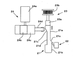
- FIG. 2 is a cross-sectional view of FIG. 1. Sectional drawing at the time of door opening of FIG. The top view of a locking mechanism. Operation
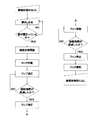
- movement explanatory drawing of FIG. FIG. 6 is a front view of FIG. 5. The lock state figure of a locking mechanism. Explanatory drawing of the drive control of this invention. Work description flowchart.
- the ultraviolet irradiation device for dental implants of the present invention includes a sealed casing 1 and a door 2 that is opened and closed with respect to the casing 1.
- the housing 1 is partitioned into a processing chamber 4 and an ozone processing chamber 5 by a partition wall 3, and an ultraviolet lamp 6 is disposed in the processing chamber 4.
- the ultraviolet lamp 6 is a low-pressure mercury lamp that emits ultraviolet light having a wavelength of 185 to 254 nm, for example, and is a U-shaped arc tube in which two linear portions extending in the depth direction of the housing 1 are connected by a curved portion. 6a, and the two linear portions are arranged so that the longitudinal direction of the linear portions is substantially horizontal, with the base 6b being attached to one end thereof. Yes.
- a pair of the ultraviolet lamps 6 are arranged so as to face each other, and reflecting mirrors 7 and 7 having a bowl-shaped cross section are provided on both sides of the ultraviolet lamps 6 and 6 so as to surround them. It has been.
- a fan 8 that circulates the gas in the housing 1 and an ozone removing unit 9 are disposed in the ozone processing chamber 5.
- the ozone removing means 9 is, for example, an ozone removing filter in which an ozone removing catalyst made of, for example, manganese dioxide is supported on a substrate made of a honeycomb structure formed of inorganic fiber paper.
- the gas containing ozone in the processing chamber 4 flows into the ozone processing chamber 5 by the fan 8, and is circulated so that the ozone is removed by the ozone removing means 9 and flows into the processing chamber 4 again.
- the open / close door 2 is a drawer type in this embodiment, and a carriage 10 is attached integrally with the door 2, and the carriage 10 is attached to the housing 1. It is guided by a provided guide 11 and can be pulled out.
- An implant support 12 is placed on the carriage 10 and is detachably fixed.
- a plurality of implants 13 in this example are supported on the implant support base 12.
- the implant support base 12 is formed with a plurality of openings 12a arranged in a line, and the implant 13 has its end 13b inserted into the opening 12a so that the screw part 13a embedded in the human body faces upward. Is supported by
- the implant support base 12 placed and fixed on the carriage 10 in this way, when the door 2 is inserted and closed from the door open state shown in FIG. 3 to the door sealed state of FIG. 6 and the implant 13 is disposed so as to be within the effective light emitting region in the longitudinal direction of the ultraviolet lamp 6.
- the door 2 is hermetically sealed with respect to the housing 1 by a sealing material.
- FIGS. 4 A lock mechanism 20 for locking the open / close door 2 in the closed state is provided, and details thereof are shown in FIGS. 4 is a top view.
- the lock mechanism 20 includes a lock bar 21, a door opening / closing detection means 22, a first lock bar fixing means 23, and a second lock bar fixing. And means 24.
- the lock bar 21 is protruded and supported on the back side of the door 2.
- the door opening / closing detection unit 22, the first lock bar fixing unit 23, and the second lock bar are fixed.
- the means 24 is provided on the housing 1 side.
- the lock bar 21 is formed with a first flat surface 21a and a second flat surface 21b on one side so as to have a first step portion 21c.
- a concave portion 21d is formed on the other side surface, and a second stepped portion 21e is formed on the distal end side.
- the door opening / closing detection means 22 is provided with a detection arm 22a, and the arm 22a is in elastic contact with the first flat surface 21a and the second flat surface 21b on one side of the lock rod 21.
- the first lock rod fixing means 23 includes a contact head portion 23a made of a magnet that contacts the tip of the lock rod 21, and a spring 23b that urges the head portion 23a downward in the drawing, that is, toward the lock rod 21 side.
- the second lock rod fixing means 22 includes a motor 24a, an eccentric piece 24b rotated thereby, and a slide engaged with the eccentric piece 24b. It consists of a moving member 24c and a projecting bar 24d projecting therefrom.
- the detection arm 22a of the door opening / closing detection means 22 is in contact with the first flat surface 21a of the lock rod 21, and the locked state of the door 2 is not detected.
- the lock rod 21 moves forward and is attracted to the contact head (magnet) 23a of the first lock rod fixing means 23 by a magnetic force.
- the impact caused by the adsorption is alleviated by the spring 23b.
- the lock bar 21 is fixed to the first lock bar fixing means 23, the door is sealed with respect to the housing.
- the detection arm 22a of the door opening / closing detection means 22 gets over the stepped portion 21c on one side of the lock rod 21 and comes into contact with the second plane 21b, and the door is closed. Detected.
- the second lock rod fixing means 24 operates to lock the lock rod 21 more firmly.
- the motor 24a rotates and the eccentric piece 24b rotates.
- the sliding member 24c moves in the right direction in the drawing, that is, toward the lock rod 21.
- the sliding member 24c is supported to be slidable with respect to the housing 1.
- the protruding rod 24 d moves forward and contacts the recess 21 d of the lock rod 21.
- the lock rod 21 is slightly moved toward the first lock rod fixing means 23 when the protruding rod 24 comes into contact with the recess 21d. Since it is pressed, the sealed state and the locked state of the door are further strengthened. If necessary, if a fixing restraining member 25 is provided on the opposite side of the lock rod 21, when the protruding rod 24d of the second lock rod fixing means 24 comes into contact with the lock rod 21, the lock rod 21 is provided. 21 is supported from the opposite side, and the lock rod 21 is not deformed and unlocked.
- the lock rod 21 integral with the door is firmly fixed by the first lock rod fixing means 23 and the second lock rod fixing means 24, so that the door 2 Is tightly sealed with respect to the housing 1, and the door is not opened unduly unless these lock rod fixing means 23, 24 are released. Thereby, ozone generated in the housing 1 is prevented from inadvertently leaking out of the housing.
- the control system is mainly composed of means for driving / detecting a structure arranged in the housing of the apparatus, and a control unit having a circuit for controlling the structure.
- a rotation sensor 30 that detects the rotation of the rotary fan 8 in the ozone treatment chamber 5 is provided, and the operating status of the rotary fan 8 is confirmed.
- the door opening / closing detection means 22 detects the opening / closing of the door 2 by the lock rod 21 which is described with reference to the drawings in FIG.
- the lighting power supply 31 is power supply means (lamp driving means) for supplying power to the ultraviolet lamp 6.
- the current sensor 32 is an ammeter of the ultraviolet lamp 6, that is, a lamp current detection means, and confirms the lighting state of the lamp 6.
- the control unit 33 includes a lock mechanism control unit 33a for instructing operation and release of the lock mechanism 20, a fan control unit 33b for instructing driving and stopping of the fan 8, a lighting control unit 33c for instructing lighting and extinguishing of the lamp 6, and a lamp 6 includes a timer circuit 33d for counting the lighting time of 6 and a memory 33e for storing the driving time of the fan 8.
- the external input means 34 is an instruction for the operator to set the lighting irradiation time of the lamp 6 and start the irradiation process, and is an external input means such as a liquid crystal touch panel.
- ⁇ Set of irradiated object (dental implant)> An operator pulls out the door 2 to place and fix the implant support base 12 on which the dental implant 13, which is an irradiation object, is supported on the carriage 10. ⁇ Close the door> Thereafter, the door 2 is closed. ⁇ Closed door detection> The open / closed state of the door 2 is detected by the door open / close detection means 22, and the information is transmitted as a signal to the control unit 33. When it is confirmed that the door is closed, the operator can input the set irradiation time using the external input means 34.
- ⁇ Setting of irradiation time> The operator manually inputs a predetermined set irradiation time by the external input means 34 (the operator's operation ends here).
- ⁇ Lock operation> When the set irradiation time and the irradiation start instruction are input to the control unit 33 by the external input unit 34, the control unit 33 operates the lock mechanism 20 to lock the door. That is, as shown in FIG. 7, the motor 24a of the second lock rod fixing means 24 is operated, and the protruding rod 24 is projected to lock the lock rod 21.
- ⁇ Lamp lighting> After the door is locked, a lighting start signal is transmitted from the control unit 33 to the lighting power source 31, and the lamp 6 starts to light up.
- a light extinction signal is transmitted from the control unit 33 to the lighting power source 31, and the lamp 6 is extinguished by stopping power feeding.
- the controller 33 confirms that the lamp 6 is turned off, the fan driving time data stored in the memory 33e in advance is read, and the fan 8 is driven for that time. ⁇ Whether operating time has passed> While the fan 8 is in operation, the rotation speed of the fan is measured by the rotation sensor 30. Information on the rotational speed of the fan is transmitted to the control unit 33. If the rotational speed of the fan 8 is within a predetermined rotational speed range, the control unit 33 determines that the fan is driven, and that if the rotational speed is out of the range, the fan is stopped.
- ⁇ Fan stop> When a predetermined fan driving time has elapsed, a fan stop instruction signal is transmitted from the control unit 33, and the fan 8 stops. The elapse of the driving time is determined by the timer circuit 33d in the control unit 33. The stop state of the fan 8 is confirmed by the fan rotation speed detected by the rotation sensor 30 described above. ⁇ Unlock> The control unit 33 confirms that the fan 8 has stopped and releases the lock. As a result, the protruding rod 24d of the second lock rod fixing means 24 in FIG. 7 moves backward, the lock on the lock rod 21 is released, and the door 2 can be opened. Thereafter, the door is opened, and the processed irradiated object is taken out.
- the control unit 33 determines that an error has occurred and stops the process.
- the lamp is not lit after the implant is set and the door is closed and locked, the process is stopped, and since ozone has not yet been generated at this point, the lock is released and the door is opened. If the lamp is turned off for some reason while the lamp is on, the process is stopped, the fan is operated for a predetermined time to perform ozone treatment, and then the lock is released and the door is opened.
- the power is forcibly cut off due to a power failure or the like while the lamp is on, the fan is operated for a predetermined time after the power is restored to perform ozone treatment, and then the lock is released.
- the opening / closing door 2 with respect to the housing 1 may be a swing-type door using a hinge in addition to the drawer-type door.
- the carriage 10 on which the implant support 12 is placed is attached to the door. It may be connected to advance or retreat, or may be of a form that is put in and out of the door.
- the door locking mechanism is not limited to the above example, and various locking mechanisms can be employed.
- the door is hermetically locked by the lock mechanism and processed.
- the door is prevented from being opened open during the work, and ozone generated in the housing is not leaked.
- the locked state is maintained until a predetermined time elapses after the lamp is turned on and the internal ozone is removed by the ozone removing means installed in the housing, the housing is sufficiently ozone treated.
- the door can be opened for the first time after reaching the above state, and there is an effect that it is possible to safely treat the implant without causing discomfort due to residual ozone.
Landscapes
- Health & Medical Sciences (AREA)
- Epidemiology (AREA)
- Life Sciences & Earth Sciences (AREA)
- Animal Behavior & Ethology (AREA)
- General Health & Medical Sciences (AREA)
- Public Health (AREA)
- Veterinary Medicine (AREA)
- Dental Prosthetics (AREA)
- Apparatus For Disinfection Or Sterilisation (AREA)
Abstract
【課題】紫外線によりインプラントの有機汚染物除去を行うためのインプラント用紫外線照射装置において、筐体内に生成されるオゾンが漏出することなく、処理後も所定のオゾン除去時間が経過するまでは扉を開くことができなくしてオゾンの流出を防止して、安全に紫外線洗浄することのできるインプラント用紫外線照射装置の構造を提供することである。 【解決手段】開閉扉を有する筐体と、該扉を筐体に密閉するロック機構と、前記筐体内に配設された紫外線ランプと、オゾン除去手段からなるとともに、前記紫外線ランプの点灯開始前に該扉をロック状態とし、当該紫外線ランプの消灯後に、オゾン除去処理を開始し、一定時間経過後に該扉のロック状態を解除する制御部を備えたことを特徴とする。
Description
この発明は、インプラントに紫外線を照射してその有機汚染物除去を行うインプラント用紫外線照射装置に関するものであり、特に、紫外線ランプを利用してデンタルインプラントの有機汚染物除去を行うインプラント用紫外線照射装置に係わるものである。
インプラント、特にデンタルインプラントは失われた歯の機能を代用させることを目的として顎骨に埋め込まれるものであり、そのデンタルインプラント手術においては、デンタルインプラントが十分に骨と結合(オッセオインテグレーション)することが肝要である。そのために、例えば、特許第3072303号公報(特許文献1)の段落0009には、デンタルインプラントに紫外線を照射することによって、当該デンタルインプラントに付着した有機汚染物を除去することが提案されている。
しかしながら、この先行文献においては単にアイディアとしての記述がなされているだけであり、これを実現した具体的な装置構造が提案されているわけではない。
しかしながら、この先行文献においては単にアイディアとしての記述がなされているだけであり、これを実現した具体的な装置構造が提案されているわけではない。
而して、デンタルインプラント手術においては、デンタルインプラントへの紫外線照射による有機汚染物の除去作業が終了した後は、当該デンタルインプラントに有機汚染物等が再度付着することを回避するために、できるだけ速やかに手術に供されることが肝要である。
しかしながら、デンタルインプラントの紫外線照射処理が終了した直後においては、当該デンタルインプラントが配置された処理室内の雰囲気ガスには、人体に有害なオゾンが含まれているため、デンタルインプラントを直ちに処理室内から取り出して手術に供することは実際上困難である。
しかしながら、デンタルインプラントの紫外線照射処理が終了した直後においては、当該デンタルインプラントが配置された処理室内の雰囲気ガスには、人体に有害なオゾンが含まれているため、デンタルインプラントを直ちに処理室内から取り出して手術に供することは実際上困難である。
また、これを回避しようとして、オゾンの生成を避けるために、デンタルインプラントが配置される処理室内を、例えば、窒素ガス等の不活性ガスによってパージする手段が考えられるが、本来的に、紫外線照射による有機物除去処理では、オゾンの存在が不可欠であって、処理室内を不活性ガスでパージしてしまうと、この不可欠のオゾンのもととなる酸素が無くなるために、紫外線によるオゾンの生成がなされず、被処理物であるデンタルインプラントに対する肝腎のオゾン処理が行われることがなく、デンタルインプラントに付着した有機物を除去することができないという矛盾が生じる。
このように、インプラントの紫外線照射処理を高い効率で行うためにはオゾンが必要であるが、一方ではこのオゾンは人体には有害であって、これが歯科医師等の作業者に悪影響を及ぼすという問題があり、作業者が安全にかつ迅速に作業できる装置の実現化が待たれている状況であった。
このように、インプラントの紫外線照射処理を高い効率で行うためにはオゾンが必要であるが、一方ではこのオゾンは人体には有害であって、これが歯科医師等の作業者に悪影響を及ぼすという問題があり、作業者が安全にかつ迅速に作業できる装置の実現化が待たれている状況であった。
この発明が解決しようとする課題は、紫外線を放射する紫外線ランプを用いて人工歯根などのインプラントの有機汚染物を除去するためのインプラント用紫外線照射装置において、紫外線照射によって発生するオゾンが処理室外に漏洩することなく、処理後には速やかにオゾンを除去して、施術のために迅速に、かつ安全にインプラントを取出すことができるようにしたインプラント用紫外線照射装置の構造を提供することである。
上記課題を解決するために、この発明に係るインプラント用紫外線照射装置は、開閉扉を有する筐体と、該扉を筐体に密閉するロック機構と、前記筐体内に配設された紫外線ランプと、オゾン除去手段からなるとともに、前記紫外線ランプの点灯開始前に該扉をロック状態とし、当該紫外線ランプの消灯後に、オゾン除去処理を開始し、一定時間経過後に該扉のロック状態を解除する制御部を備えたことを特徴とする。
また、前記紫外線ランプが、低圧水銀ランプであることを特徴とする。
また、前記扉には、インプラント支持台が着脱自在に載置されるキャリッジが設けられていることを特徴とする。
また、前記紫外線ランプは、筐体内に配設されたインプラントに対して、その両側から紫外線を照射するように配置されていることを特徴とする。
また、前記紫外線ランプの両側には、該紫外線ランプからの光を反射する反射鏡が備えられていることを特徴とする。
また、前記オゾン除去手段が、オゾン除去フィルターからなり、前記筐体内にガスを循環するファンを備えたことを特徴とする。
また、前記紫外線ランプが、低圧水銀ランプであることを特徴とする。
また、前記扉には、インプラント支持台が着脱自在に載置されるキャリッジが設けられていることを特徴とする。
また、前記紫外線ランプは、筐体内に配設されたインプラントに対して、その両側から紫外線を照射するように配置されていることを特徴とする。
また、前記紫外線ランプの両側には、該紫外線ランプからの光を反射する反射鏡が備えられていることを特徴とする。
また、前記オゾン除去手段が、オゾン除去フィルターからなり、前記筐体内にガスを循環するファンを備えたことを特徴とする。
この発明のインプラント用紫外線照射装置によれば、密閉筐体内での紫外線ランプによるインプラントの有機汚染物除去作業中に、筐体内部で発生するオゾンが外部に漏れることがなく、かつ、紫外線照射処理後の一定時間は扉のロック状態が維持されて不用意に開扉されることがなく、その間に筐体内のオゾン除去処理が行われるので、作業者に有害なオゾンが装置外に発散されることがなく、オゾン処理が終了した後にインプラントを取出すので、安全な作業が確保される。
図1に示されるように、本発明のデンタルインプラント用紫外線照射装置は、密閉型の筐体1と、該筐体1に対して気密に開閉される扉2とからなる。筐体1内は隔壁3によって処理室4とオゾン処理室5とに区画され、処理室4内には紫外線ランプ6が配設されている。
上記紫外線ランプ6は、例えば波長185~254nmの紫外線を放射する低圧水銀ランプであって、筐体1の奥行き方向に伸びる2つの直線状部分が湾曲部分によって連結されてなるU字管状の発光管6aを有し、この2つの直線状部分が互いに上下に位置する関係で、直線状部分の長手方向が略水平方向となるように配置されていて、その一方端にはベース6bが取り付けられている。
図2に示されるように、該紫外線ランプ6は対向するように一対配置されていて、これら紫外線ランプ6、6の両側にはこれを取り囲むように、断面樋状の反射鏡7、7が設けられている。
オゾン処理室5には、筐体1内のガスを循環させるファン8と、オゾン除去手段9が配置されている。オゾン除去手段9は、例えば、無機繊維ペーパーにより形成されたハニカム構造体からなる基体に、たとえば二酸化マンガンよりなるオゾン除去用触媒が担持されてなるオゾン除去フィルターである。
前記ファン8によって、処理室4内のオゾンを含むガスはオゾン処理室5に流れ、オゾン除去手段9によってオゾンを除去されて、再び処理室4に流れるように循環される。
上記紫外線ランプ6は、例えば波長185~254nmの紫外線を放射する低圧水銀ランプであって、筐体1の奥行き方向に伸びる2つの直線状部分が湾曲部分によって連結されてなるU字管状の発光管6aを有し、この2つの直線状部分が互いに上下に位置する関係で、直線状部分の長手方向が略水平方向となるように配置されていて、その一方端にはベース6bが取り付けられている。
図2に示されるように、該紫外線ランプ6は対向するように一対配置されていて、これら紫外線ランプ6、6の両側にはこれを取り囲むように、断面樋状の反射鏡7、7が設けられている。
オゾン処理室5には、筐体1内のガスを循環させるファン8と、オゾン除去手段9が配置されている。オゾン除去手段9は、例えば、無機繊維ペーパーにより形成されたハニカム構造体からなる基体に、たとえば二酸化マンガンよりなるオゾン除去用触媒が担持されてなるオゾン除去フィルターである。
前記ファン8によって、処理室4内のオゾンを含むガスはオゾン処理室5に流れ、オゾン除去手段9によってオゾンを除去されて、再び処理室4に流れるように循環される。
扉2の開放状態を示す図3も参照して、開閉扉2は、この実施例では引き出し型であって、扉2と一体にキャリッジ10が取り付けられており、該キャリッジ10は筐体1に設けられたガイド11によってガイドされて引き出し自在となっている。
前記キャリッジ10にはインプラント支持台12が載置され着脱可能に固定される。該インプラント支持台12には複数の、この例では6本のインプラント13が支持されている。前記インプラント支持台12には複数の開口12aが一列に並ぶように形成されていて、インプラント13は、人体に埋め込まれる螺子部13aが上方を向くように、その端部13bを該開口12aに挿入することによって支持される。
前記キャリッジ10にはインプラント支持台12が載置され着脱可能に固定される。該インプラント支持台12には複数の、この例では6本のインプラント13が支持されている。前記インプラント支持台12には複数の開口12aが一列に並ぶように形成されていて、インプラント13は、人体に埋め込まれる螺子部13aが上方を向くように、その端部13bを該開口12aに挿入することによって支持される。
こうしてキャリッジ10上に載置固定されたインプラント支持台12は、扉2が図3に示す扉開放状態から図1の扉密閉状態に挿入されて閉められたときに、前記一対の紫外線ランプ6、6間に位置し、かつインプラント13が該紫外線ランプ6の長さ方向の有効発光領域内に収まるように配置される。
図示されてはいないが、この扉2は筐体1に対してシーリング材によって気密に密閉される。
図示されてはいないが、この扉2は筐体1に対してシーリング材によって気密に密閉される。
開閉扉2を閉状態にロックするためのロック機構20が設けられており、その詳細が図4~図7に示されている。
図4は上面図であって、同図に示されるように、ロック機構20は、ロック棒21と、扉開閉検知手段22と、第一のロック棒固定手段23と、第二のロック棒固定手段24とより構成される。
ロック棒21は図1、3に示されるように、扉2の裏面側に突設支持されており、一方、扉開閉検知手段22、第1のロック棒固定手段23、第2のロック棒固定手段24は、筐体1側に設けられている。
前記ロック棒21には、一側面に第1平面21aと第2平面21bが第1の段部21cを有するように形成されている。そして、他側面には凹部21dが形成されて先端側に第2の段部21eが形成されている。
前記扉開閉検知手段22には検知アーム22aが設けられており、該アーム22aは、前記ロック棒21の一側面の第1平面21a、第2平面21bに弾性的に当接されている。
前記第1ロック棒固定手段23は、ロック棒21の先端に当接する磁石からなる当接頭部23aと、これを図の下方に、即ちロック棒21側に付勢するバネ23bとを備える。
そして、図5の前面図である図6も参照して、第2ロック棒固定手段22は、モータ24aと、これにより回転される偏芯駒24bと、該偏芯駒24bと係合する摺動部材24cと、これに突設された突出棒24dとからなる。
図4は上面図であって、同図に示されるように、ロック機構20は、ロック棒21と、扉開閉検知手段22と、第一のロック棒固定手段23と、第二のロック棒固定手段24とより構成される。
ロック棒21は図1、3に示されるように、扉2の裏面側に突設支持されており、一方、扉開閉検知手段22、第1のロック棒固定手段23、第2のロック棒固定手段24は、筐体1側に設けられている。
前記ロック棒21には、一側面に第1平面21aと第2平面21bが第1の段部21cを有するように形成されている。そして、他側面には凹部21dが形成されて先端側に第2の段部21eが形成されている。
前記扉開閉検知手段22には検知アーム22aが設けられており、該アーム22aは、前記ロック棒21の一側面の第1平面21a、第2平面21bに弾性的に当接されている。
前記第1ロック棒固定手段23は、ロック棒21の先端に当接する磁石からなる当接頭部23aと、これを図の下方に、即ちロック棒21側に付勢するバネ23bとを備える。
そして、図5の前面図である図6も参照して、第2ロック棒固定手段22は、モータ24aと、これにより回転される偏芯駒24bと、該偏芯駒24bと係合する摺動部材24cと、これに突設された突出棒24dとからなる。
扉2のロック作動について説明すると以下の通りである。
図3および図4に示す扉開放状態にあっては、扉開閉検知手段22の検知アーム22aはロック棒21の第1平面21aに当接していて、扉2のロック状態を検知していない。
扉2が閉められると、ロック棒21が前進して第1のロック棒固定手段23の当接頭部(磁石)23aに磁力により吸着される。この際の吸着による衝撃はバネ23bによって緩和される。こうして、ロック棒21が第1のロック棒固定手段23に固定されると、扉は筐体に対して密閉される。
図3および図4に示す扉開放状態にあっては、扉開閉検知手段22の検知アーム22aはロック棒21の第1平面21aに当接していて、扉2のロック状態を検知していない。
扉2が閉められると、ロック棒21が前進して第1のロック棒固定手段23の当接頭部(磁石)23aに磁力により吸着される。この際の吸着による衝撃はバネ23bによって緩和される。こうして、ロック棒21が第1のロック棒固定手段23に固定されると、扉は筐体に対して密閉される。
このとき、図5に示されるように、扉開閉検知手段22の検知アーム22aは、ロック棒21の一側面の段部21cを乗り越えて第2平面21bに当接され、扉が閉まったことが検知される。
この検知信号を受けて第2のロック棒固定手段24が作動してロック棒21を更に強固にロックする。
具体的には、図6も併せて参照して、扉開閉検知手段22からの信号を受けて、モータ24aが回転し、偏芯駒24bが回転する。この偏芯駒24bの回転により、図6(B)に示すように、摺動部材24cが図の右方向、即ち、ロック棒21方向に移動する。なお、該摺動部材24cは、図示されないが、筐体1に対して摺動可能に支持されている。
この検知信号を受けて第2のロック棒固定手段24が作動してロック棒21を更に強固にロックする。
具体的には、図6も併せて参照して、扉開閉検知手段22からの信号を受けて、モータ24aが回転し、偏芯駒24bが回転する。この偏芯駒24bの回転により、図6(B)に示すように、摺動部材24cが図の右方向、即ち、ロック棒21方向に移動する。なお、該摺動部材24cは、図示されないが、筐体1に対して摺動可能に支持されている。
これにより、図7に示すように、突出棒24dが前進してロック棒21の凹部21dに当接する。なお、この際、第2の段部21eに傾斜をつけておくことにより、前記突出棒24が凹部21dに当接するときに、ロック棒21を第1のロック棒固定手段23方向に若干量だけ押し付けるので、扉の密閉状態およびロック状態が更に強固になる。
なお、必要に応じて、ロック棒21の反対側に固定抑え部材25を設けておけば、第2のロック棒固定手段24の突出棒24dがロック棒21に当接したときに、該ロック棒21を反対側から支えることになり、当該ロック棒21が変形してロックが解除されるようなことがない。
なお、必要に応じて、ロック棒21の反対側に固定抑え部材25を設けておけば、第2のロック棒固定手段24の突出棒24dがロック棒21に当接したときに、該ロック棒21を反対側から支えることになり、当該ロック棒21が変形してロックが解除されるようなことがない。
上記のように、扉2が閉じられたとき、扉と一体のロック棒21が第1のロック棒固定手段23と、第2のロック棒固定手段24とによって強固に固定されるので、扉2が筐体1に対してしっかりと密閉されるとともに、これらのロック棒固定手段23、24が解除されない限り扉がみだりに開けられることもない。
これにより、筐体1内で生成されたオゾンが不用意に筐体外に漏出することが防止されるものである。
これにより、筐体1内で生成されたオゾンが不用意に筐体外に漏出することが防止されるものである。
次いで、本発明のインプラント用紫外線照射装置の光洗浄工程および扉ロック機構作動工程について、図8および図9に基づいて説明する。
制御系統は、主に装置の筐体内に配置された構造物を駆動・検知する手段と、それを制御する回路等を有する制御部とから構成されている。
図8に示されるように、オゾン処理室5内の回転ファン8の回転を検知する回転センサ30を備え、回転ファン8の稼働状況を確認するものである。
扉開閉検知手段22は、上述の図4以下の図面に基いて説明した、扉2の開閉に応じて進退するロック棒21によって扉2の開閉を検知するものである。
点灯電源31は、紫外線ランプ6に電力を供給する給電手段(ランプ駆動手段)である。そして、カレントセンサ32は紫外線ランプ6の電流計、即ち、ランプ電流検知手段であって、ランプ6の点灯状態を確認する。
制御系統は、主に装置の筐体内に配置された構造物を駆動・検知する手段と、それを制御する回路等を有する制御部とから構成されている。
図8に示されるように、オゾン処理室5内の回転ファン8の回転を検知する回転センサ30を備え、回転ファン8の稼働状況を確認するものである。
扉開閉検知手段22は、上述の図4以下の図面に基いて説明した、扉2の開閉に応じて進退するロック棒21によって扉2の開閉を検知するものである。
点灯電源31は、紫外線ランプ6に電力を供給する給電手段(ランプ駆動手段)である。そして、カレントセンサ32は紫外線ランプ6の電流計、即ち、ランプ電流検知手段であって、ランプ6の点灯状態を確認する。
制御部33は、ロック機構20の作動、解除を指示するロック機構制御手段33a、ファン8の駆動、停止を指示するファン制御手段33b、ランプ6の点灯、消灯を指示する点灯制御手段33c、ランプ6の点灯時間をカウントするタイマー回路33d、および、ファン8の駆動時間を記憶しておくメモリ33eとからなる。
外部入力手段34は、作業者がランプ6の点灯照射時間の設定、照射処理開始を指示するものであり、例えば液晶タッチパネル等の外部入力手段である。
外部入力手段34は、作業者がランプ6の点灯照射時間の設定、照射処理開始を指示するものであり、例えば液晶タッチパネル等の外部入力手段である。
上記構成において、図9を参照して操作を説明する。
<被照射物(デンタルインプラント)のセット>
作業者が扉2を引き出して、被照射物であるデンタルインプラント13が支持されたインプラント支持台12をキャリッジ10上に載置固定する。
<扉を閉める>
その後、扉2が閉められる。
<扉の閉検知>
扉2の開閉状態は扉開閉検知手段22によって検知され、その情報が制御部33へ信号として送信される。
扉が閉まっている状態が確認されると、作業者が外部入力手段34を利用して設定照射時間を入力できるようになる。
<照射時間の設定>
作業者は、外部入力手段34によって、所定の設定照射時間を手入力する(作業者の操作はこれで終了)。
<ロック作動>
外部入力手段34により制御部33に設定照射時間と、照射開始指示が入力されると、制御部33はロック機構20を動作させて扉のロックを行う。
即ち、図7に示すように、第2のロック棒固定手段24のモータ24aを作動し、突出棒24を突出させてロック棒21をロックする。
<ランプ点灯>
扉がロックされた後、制御部33から点灯電源31へ点灯開始の信号が送信され、これによりランプ6が点灯を開始する。
<被照射物(デンタルインプラント)のセット>
作業者が扉2を引き出して、被照射物であるデンタルインプラント13が支持されたインプラント支持台12をキャリッジ10上に載置固定する。
<扉を閉める>
その後、扉2が閉められる。
<扉の閉検知>
扉2の開閉状態は扉開閉検知手段22によって検知され、その情報が制御部33へ信号として送信される。
扉が閉まっている状態が確認されると、作業者が外部入力手段34を利用して設定照射時間を入力できるようになる。
<照射時間の設定>
作業者は、外部入力手段34によって、所定の設定照射時間を手入力する(作業者の操作はこれで終了)。
<ロック作動>
外部入力手段34により制御部33に設定照射時間と、照射開始指示が入力されると、制御部33はロック機構20を動作させて扉のロックを行う。
即ち、図7に示すように、第2のロック棒固定手段24のモータ24aを作動し、突出棒24を突出させてロック棒21をロックする。
<ランプ点灯>
扉がロックされた後、制御部33から点灯電源31へ点灯開始の信号が送信され、これによりランプ6が点灯を開始する。
<照射時間の経過>
ランプ点灯中は、常時カレントセンサ32によりランプ電流が観測され、ランプ6の点灯が確認される。即ち、所定の範囲内の電流値が測定されているときはランプが点灯、その範囲を逸脱するときはランプが不点灯、であることを制御部33が判断する。
なお、ランプが不点灯と判断されたときは、装置の動作がエラーとして装置が停止される。
<ランプ消灯>
点灯時間の経過は、制御部33内のタイマー回路33dが判断する。ランプの消灯状態は、上述のカレントセンサ32が検知するランプ電流により確認する。
所定の照射時間が経過すると、制御部33より点灯電源31に消灯信号が送信され、給電が止まることでランプ6が消灯する。
<ファン駆動>
制御部33がランプ6の消灯を確認すると、あらかじめメモリ33eに記憶させたファン駆動時間のデータを読み出し、その時間だけファン8を駆動する。
<稼働時間が経過したか>
ファン8の稼動中は、回転センサ30によりファンの回転数を測定する。このファンの回転数の情報は制御部33に送信される。
ファン8の回転数が所定の回転数の範囲内であれば、ファンが駆動、その範囲を逸脱するときはファンが停止、であることを制御部33が判断する。
ランプ点灯中は、常時カレントセンサ32によりランプ電流が観測され、ランプ6の点灯が確認される。即ち、所定の範囲内の電流値が測定されているときはランプが点灯、その範囲を逸脱するときはランプが不点灯、であることを制御部33が判断する。
なお、ランプが不点灯と判断されたときは、装置の動作がエラーとして装置が停止される。
<ランプ消灯>
点灯時間の経過は、制御部33内のタイマー回路33dが判断する。ランプの消灯状態は、上述のカレントセンサ32が検知するランプ電流により確認する。
所定の照射時間が経過すると、制御部33より点灯電源31に消灯信号が送信され、給電が止まることでランプ6が消灯する。
<ファン駆動>
制御部33がランプ6の消灯を確認すると、あらかじめメモリ33eに記憶させたファン駆動時間のデータを読み出し、その時間だけファン8を駆動する。
<稼働時間が経過したか>
ファン8の稼動中は、回転センサ30によりファンの回転数を測定する。このファンの回転数の情報は制御部33に送信される。
ファン8の回転数が所定の回転数の範囲内であれば、ファンが駆動、その範囲を逸脱するときはファンが停止、であることを制御部33が判断する。
<ファンの停止>
所定のファン駆動時間が経過すると、制御部33よりファン停止指示の信号が送信され、ファン8が停止する。
上記の駆動時間の経過は、制御部33内のタイマー回路33dが判断する。
ファン8の停止状態は、上述の回転センサ30が検知するファン回転数により確認する。
<ロックの解除>
制御部33は、ファン8が停止したことを確認して、ロックを解除する。
これにより、図7における、第2のロック棒固定手段24の突出棒24dが後退し、ロック棒21に対するロックが解除され、扉2は開放できる。
その後、扉を開放し、処理された被照射物を取り出すものである。
所定のファン駆動時間が経過すると、制御部33よりファン停止指示の信号が送信され、ファン8が停止する。
上記の駆動時間の経過は、制御部33内のタイマー回路33dが判断する。
ファン8の停止状態は、上述の回転センサ30が検知するファン回転数により確認する。
<ロックの解除>
制御部33は、ファン8が停止したことを確認して、ロックを解除する。
これにより、図7における、第2のロック棒固定手段24の突出棒24dが後退し、ロック棒21に対するロックが解除され、扉2は開放できる。
その後、扉を開放し、処理された被照射物を取り出すものである。
上記操作中、下記の状態のときは、制御部33はエラーが発生したと判断して処理を中止する。
インプラントをセットし、扉を閉めロックした後にランプ6が点灯しなかったときは、処理を中止して、この時点では未だオゾンが発生していないので、そのままロックを解除し扉を開放する。
ランプ点灯中に、何らかの原因で消灯した場合には、処理を中止して、所定時間だけファンを稼働してオゾン処理を行い、その後にロックを解除し、扉を開放する。
また、ランプ点灯中に、停電などにより強制的に電源が切断された場合には、電力が復帰した後にファンを所定時間だけ稼働してオゾン処理を行い、その後にロックを解除する。
インプラントをセットし、扉を閉めロックした後にランプ6が点灯しなかったときは、処理を中止して、この時点では未だオゾンが発生していないので、そのままロックを解除し扉を開放する。
ランプ点灯中に、何らかの原因で消灯した場合には、処理を中止して、所定時間だけファンを稼働してオゾン処理を行い、その後にロックを解除し、扉を開放する。
また、ランプ点灯中に、停電などにより強制的に電源が切断された場合には、電力が復帰した後にファンを所定時間だけ稼働してオゾン処理を行い、その後にロックを解除する。
なお、筐体1に対する開閉扉2としては、上記引き出し型の扉以外に、蝶番によるスイング式の扉であってもよく、その場合、インプラント支持台12を載置するキャリッジ10は、該扉に連結されて進退するものであってもよいし、また、扉とは別体に出し入れする形式であってもよい。
また、扉のロック機構も上記の例に限られず、種々のロック機構を採用することができる。
また、扉のロック機構も上記の例に限られず、種々のロック機構を採用することができる。
66
以上説明したように、本発明のインプラント用紫外線照射装置においては、インプラントが支持されたインプラント支持台を載置したキャリッジを筐体内に配置した後は、ロック機構により扉を気密にロックし、処理作業中に扉がみだりに開けられることを防止して、筐体内に発生するオゾンが漏出することがない。また、ランプの点灯後にも所定時間が経過して、筐体内に設置されたオゾン除去手段によって内部のオゾンが除去されるまでは前記ロック状態が維持されるので、筐体内が十分にオゾン処理された状態になって初めて扉を開くことができて、作業者に残留オゾンによる不快感を与えることがなく、安全なインプラントの処理が行えるという効果を奏するものである。
以上説明したように、本発明のインプラント用紫外線照射装置においては、インプラントが支持されたインプラント支持台を載置したキャリッジを筐体内に配置した後は、ロック機構により扉を気密にロックし、処理作業中に扉がみだりに開けられることを防止して、筐体内に発生するオゾンが漏出することがない。また、ランプの点灯後にも所定時間が経過して、筐体内に設置されたオゾン除去手段によって内部のオゾンが除去されるまでは前記ロック状態が維持されるので、筐体内が十分にオゾン処理された状態になって初めて扉を開くことができて、作業者に残留オゾンによる不快感を与えることがなく、安全なインプラントの処理が行えるという効果を奏するものである。
1 筐体
2 扉
3 隔壁
4 処理室
5 オゾン処理室
6 紫外線ランプ
7 反射鏡
8 ファン
9 オゾン除去手段
10 キャリッジ
11 ガイド
12 インプラント支持台
13 デンタルインプラント
20 ロック機構
21 ロック棒
22 扉開閉検知手段
23 第1のロック棒固定手段
24 第2のロック棒固定手段
25 固定抑え部材
30 回転センサ
31 点灯電源
32 カレントセンサ
33 制御部
34 外部入力手段
2 扉
3 隔壁
4 処理室
5 オゾン処理室
6 紫外線ランプ
7 反射鏡
8 ファン
9 オゾン除去手段
10 キャリッジ
11 ガイド
12 インプラント支持台
13 デンタルインプラント
20 ロック機構
21 ロック棒
22 扉開閉検知手段
23 第1のロック棒固定手段
24 第2のロック棒固定手段
25 固定抑え部材
30 回転センサ
31 点灯電源
32 カレントセンサ
33 制御部
34 外部入力手段
Claims (6)
- 紫外線によりインプラントの有機汚染物除去を行うためのインプラント用紫外線照射装置において、
前記インプラント用紫外線照射装置は、開閉扉を有する筐体と、該扉を筐体に密閉するロック機構と、前記筐体内に配設された紫外線ランプと、オゾン除去手段からなるとともに、
前記紫外線ランプの点灯開始前に該扉をロック状態とし、当該紫外線ランプの消灯後に、オゾン除去処理を開始し、一定時間経過後に該扉のロック状態を解除する制御部を備えたことを特徴とするインプラント用紫外線照射装置。 - 前記紫外線ランプが、低圧水銀ランプであることを特徴とする請求項1に記載のインプラント用紫外線照射装置。
- 前記扉には、インプラント支持台が着脱自在に載置されるキャリッジが設けられていることを特徴とする請求項1に記載のインプラント用紫外線照射装置。
- 前記紫外線ランプは、筐体内に配設されたインプラントに対して、その両側から紫外線を照射するように配置されていることを特徴とする請求項1に記載のインプラント用紫外線照射装置。
- 前記紫外線ランプの両側には、該紫外線ランプからの光を反射する反射鏡が備えられていることを特徴とする請求項4に記載のインプラント用紫外線照射装置。
- 前記オゾン除去手段が、オゾン除去フィルターからなり、前記筐体内にガスを循環するファンを備えたことを特徴とする請求項1に記載のインプラント用紫外線照射装置。
Applications Claiming Priority (2)
| Application Number | Priority Date | Filing Date | Title |
|---|---|---|---|
| JP2011017433A JP2012157412A (ja) | 2011-01-31 | 2011-01-31 | インプラント用紫外線照射装置 |
| JP2011-017433 | 2011-01-31 |
Publications (1)
| Publication Number | Publication Date |
|---|---|
| WO2012105093A1 true WO2012105093A1 (ja) | 2012-08-09 |
Family
ID=46602327
Family Applications (1)
| Application Number | Title | Priority Date | Filing Date |
|---|---|---|---|
| PCT/JP2011/073920 Ceased WO2012105093A1 (ja) | 2011-01-31 | 2011-10-18 | インプラント用紫外線照射装置 |
Country Status (2)
| Country | Link |
|---|---|
| JP (1) | JP2012157412A (ja) |
| WO (1) | WO2012105093A1 (ja) |
Cited By (4)
| Publication number | Priority date | Publication date | Assignee | Title |
|---|---|---|---|---|
| EP3266411A4 (en) * | 2015-03-05 | 2018-05-30 | Ushio Denki Kabushiki Kaisha | Ultraviolet irradiation device for implant |
| CN108294493A (zh) * | 2017-12-29 | 2018-07-20 | 陈雪龙 | 一种除臭防霉的多功能鞋柜 |
| CN110403720A (zh) * | 2019-09-03 | 2019-11-05 | 恒泰医疗科技(天津)有限公司 | 种植体智能活化仪 |
| CN112125280A (zh) * | 2019-06-25 | 2020-12-25 | 株式会社奥珂制作所 | 臭氧生成装置和臭氧生成方法 |
Families Citing this family (5)
| Publication number | Priority date | Publication date | Assignee | Title |
|---|---|---|---|---|
| JP6841631B2 (ja) * | 2016-09-30 | 2021-03-10 | 株式会社オーク製作所 | 紫外線照射装置 |
| KR102064951B1 (ko) | 2018-01-19 | 2020-01-10 | 주식회사 디오 | 치아 임플란트의 표면처리용 자외선 조사장치 |
| KR102106993B1 (ko) * | 2018-01-19 | 2020-05-06 | 주식회사 디오 | 치아 임플란트의 표면처리용 자외선 조사장치 |
| KR102116867B1 (ko) | 2018-05-08 | 2020-05-29 | 주식회사 원익큐엔씨 | 임플란트 표면개질 처리장치 |
| KR102076051B1 (ko) * | 2019-03-29 | 2020-02-12 | 주식회사 디오 | 의료용 금속의 표면처리장치 |
Citations (6)
| Publication number | Priority date | Publication date | Assignee | Title |
|---|---|---|---|---|
| JPH01207070A (ja) * | 1987-10-22 | 1989-08-21 | Jr Robert E Duthie | 滅菌方法および装置 |
| JPH04264723A (ja) * | 1991-02-20 | 1992-09-21 | Toshiba Lighting & Technol Corp | 紫外線照射装置 |
| JP2000066003A (ja) * | 1998-08-24 | 2000-03-03 | Nikon Corp | 光学部品の洗浄方法 |
| JP2005342314A (ja) * | 2004-06-04 | 2005-12-15 | Koichi Arai | 殺菌装置 |
| JP2009082359A (ja) * | 2007-09-28 | 2009-04-23 | Iwasaki Electric Co Ltd | 殺菌装置 |
| JP2010259648A (ja) * | 2009-05-08 | 2010-11-18 | Tso3 Inc | オゾン殺菌方法とその装置 |
-
2011
- 2011-01-31 JP JP2011017433A patent/JP2012157412A/ja active Pending
- 2011-10-18 WO PCT/JP2011/073920 patent/WO2012105093A1/ja not_active Ceased
Patent Citations (6)
| Publication number | Priority date | Publication date | Assignee | Title |
|---|---|---|---|---|
| JPH01207070A (ja) * | 1987-10-22 | 1989-08-21 | Jr Robert E Duthie | 滅菌方法および装置 |
| JPH04264723A (ja) * | 1991-02-20 | 1992-09-21 | Toshiba Lighting & Technol Corp | 紫外線照射装置 |
| JP2000066003A (ja) * | 1998-08-24 | 2000-03-03 | Nikon Corp | 光学部品の洗浄方法 |
| JP2005342314A (ja) * | 2004-06-04 | 2005-12-15 | Koichi Arai | 殺菌装置 |
| JP2009082359A (ja) * | 2007-09-28 | 2009-04-23 | Iwasaki Electric Co Ltd | 殺菌装置 |
| JP2010259648A (ja) * | 2009-05-08 | 2010-11-18 | Tso3 Inc | オゾン殺菌方法とその装置 |
Cited By (5)
| Publication number | Priority date | Publication date | Assignee | Title |
|---|---|---|---|---|
| EP3266411A4 (en) * | 2015-03-05 | 2018-05-30 | Ushio Denki Kabushiki Kaisha | Ultraviolet irradiation device for implant |
| CN108294493A (zh) * | 2017-12-29 | 2018-07-20 | 陈雪龙 | 一种除臭防霉的多功能鞋柜 |
| CN112125280A (zh) * | 2019-06-25 | 2020-12-25 | 株式会社奥珂制作所 | 臭氧生成装置和臭氧生成方法 |
| CN112125280B (zh) * | 2019-06-25 | 2024-05-10 | 株式会社奥珂制作所 | 臭氧生成装置和臭氧生成方法 |
| CN110403720A (zh) * | 2019-09-03 | 2019-11-05 | 恒泰医疗科技(天津)有限公司 | 种植体智能活化仪 |
Also Published As
| Publication number | Publication date |
|---|---|
| JP2012157412A (ja) | 2012-08-23 |
Similar Documents
| Publication | Publication Date | Title |
|---|---|---|
| JP2012157412A (ja) | インプラント用紫外線照射装置 | |
| JP4867883B2 (ja) | 殺菌装置 | |
| JP6778003B2 (ja) | オゾン生成装置及びオゾン処理装置 | |
| JP5387537B2 (ja) | デンタルインプラント用光照射装置 | |
| JP4176236B2 (ja) | 処理装置における紫外線ランプの光量測定方法及び装置 | |
| JP5423634B2 (ja) | 生体インプラント用洗浄処理装置 | |
| KR101705830B1 (ko) | 치아 임플란트용 포장용기 | |
| JP5585473B2 (ja) | インプラント用紫外線照射装置 | |
| JP2007259715A (ja) | 培養装置 | |
| KR101675508B1 (ko) | 치아 임플란트용 포장용기 | |
| JP2016030008A (ja) | 紫外線照射装置 | |
| JP5838566B2 (ja) | インプラント用紫外線照射装置 | |
| KR20220010617A (ko) | Uv-led를 이용한 차량 내부 살균장치 | |
| JP2010068911A (ja) | 高圧蒸気滅菌器 | |
| JP7584995B2 (ja) | 活性酸素供給装置 | |
| JP4619044B2 (ja) | 殺菌装置 | |
| KR102103290B1 (ko) | 자외선 방전램프 장치 | |
| JP2005211649A (ja) | 歯科で使われるハンドピース用紫外線消毒器 | |
| JP2019217011A (ja) | 除染パスボックス | |
| JP2006145539A (ja) | 滅菌装置を有するクライオスタット | |
| JP5299451B2 (ja) | インプラント用紫外線照射装置 | |
| CN112984921A (zh) | 壁面安装系统 | |
| JP2012000118A (ja) | 人工歯根の有機汚染物除去装置 | |
| KR102076051B1 (ko) | 의료용 금속의 표면처리장치 | |
| JP2020193147A (ja) | オゾン処理装置 |
Legal Events
| Date | Code | Title | Description |
|---|---|---|---|
| 121 | Ep: the epo has been informed by wipo that ep was designated in this application |
Ref document number: 11857922 Country of ref document: EP Kind code of ref document: A1 |
|
| NENP | Non-entry into the national phase |
Ref country code: DE |
|
| 122 | Ep: pct application non-entry in european phase |
Ref document number: 11857922 Country of ref document: EP Kind code of ref document: A1 |