WO2012102213A1 - 成形方法 - Google Patents
成形方法 Download PDFInfo
- Publication number
- WO2012102213A1 WO2012102213A1 PCT/JP2012/051264 JP2012051264W WO2012102213A1 WO 2012102213 A1 WO2012102213 A1 WO 2012102213A1 JP 2012051264 W JP2012051264 W JP 2012051264W WO 2012102213 A1 WO2012102213 A1 WO 2012102213A1
- Authority
- WO
- WIPO (PCT)
- Prior art keywords
- glass plate
- mold
- side portion
- molding
- inner space
- Prior art date
- Legal status (The legal status is an assumption and is not a legal conclusion. Google has not performed a legal analysis and makes no representation as to the accuracy of the status listed.)
- Ceased
Links
Images




Classifications
-
- B—PERFORMING OPERATIONS; TRANSPORTING
- B29—WORKING OF PLASTICS; WORKING OF SUBSTANCES IN A PLASTIC STATE IN GENERAL
- B29C—SHAPING OR JOINING OF PLASTICS; SHAPING OF MATERIAL IN A PLASTIC STATE, NOT OTHERWISE PROVIDED FOR; AFTER-TREATMENT OF THE SHAPED PRODUCTS, e.g. REPAIRING
- B29C45/00—Injection moulding, i.e. forcing the required volume of moulding material through a nozzle into a closed mould; Apparatus therefor
- B29C45/16—Making multilayered or multicoloured articles
- B29C45/1671—Making multilayered or multicoloured articles with an insert
-
- B—PERFORMING OPERATIONS; TRANSPORTING
- B29—WORKING OF PLASTICS; WORKING OF SUBSTANCES IN A PLASTIC STATE IN GENERAL
- B29C—SHAPING OR JOINING OF PLASTICS; SHAPING OF MATERIAL IN A PLASTIC STATE, NOT OTHERWISE PROVIDED FOR; AFTER-TREATMENT OF THE SHAPED PRODUCTS, e.g. REPAIRING
- B29C45/00—Injection moulding, i.e. forcing the required volume of moulding material through a nozzle into a closed mould; Apparatus therefor
- B29C45/16—Making multilayered or multicoloured articles
- B29C45/1635—Making multilayered or multicoloured articles using displaceable mould parts, e.g. retractable partition between adjacent mould cavities
-
- B—PERFORMING OPERATIONS; TRANSPORTING
- B29—WORKING OF PLASTICS; WORKING OF SUBSTANCES IN A PLASTIC STATE IN GENERAL
- B29C—SHAPING OR JOINING OF PLASTICS; SHAPING OF MATERIAL IN A PLASTIC STATE, NOT OTHERWISE PROVIDED FOR; AFTER-TREATMENT OF THE SHAPED PRODUCTS, e.g. REPAIRING
- B29C45/00—Injection moulding, i.e. forcing the required volume of moulding material through a nozzle into a closed mould; Apparatus therefor
- B29C45/14—Injection moulding, i.e. forcing the required volume of moulding material through a nozzle into a closed mould; Apparatus therefor incorporating preformed parts or layers, e.g. injection moulding around inserts or for coating articles
- B29C45/14336—Coating a portion of the article, e.g. the edge of the article
- B29C45/14434—Coating brittle material, e.g. glass
Definitions
- the present invention relates to a molding method in which a glass plate is used as an insert and a synthetic resin molding is formed on the entire circumference of the glass plate.
- such a glass plate serving as an insert is set in a slide core having a frame shape, and a synthetic resin serving as a resin frame is placed in a gap formed by retreating the slide core.
- a synthetic resin serving as a resin frame is placed in a gap formed by retreating the slide core.
- the main problem to be solved by the present invention is that the synthetic resin molding part can be easily and properly molded in a manner in which the deformation or breakage of the glass sheet is not caused as much as possible. It is in.
- the molding method is a molding method in which a glass plate is used as an insert, and a molded portion of a synthetic resin is formed on the entire circumference of the glass plate, A pair of male and female main molds and one of the pair of main molds are movably combined in the same direction as the mold dividing direction of the pair of main molds, and are positioned in the main mold inner space at the advanced position.
- the filling pressure of the synthetic resin serving as the primary side portion does not act on the glass plate, and the force generated by molding shrinkage after filling also acts on the glass plate until the molding of the secondary side portion. There is nothing. Accordingly, since the outer shape of the molded product including the glass plate is configured, the primary side portion having a large molding shrinkage rate can be prevented from affecting the glass plate as much as possible.
- a synthetic resin molding part can be easily and appropriately molded in a manner in which the deformation or breakage of the glass plate is not caused as much as possible.
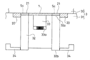
- FIG. 1 is a configuration diagram showing an example of a mold for performing a molding method according to an embodiment of the present invention, and shows a state immediately after molding a primary portion of a molding part.
- FIG. 2 is a configuration diagram showing a state immediately after the secondary side portion of the molding part is molded from the state of FIG.
- FIG. 3 is a plan view showing an example of a molded product obtained by the molding method according to the embodiment.
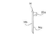
- FIG. 4 is a left side view of the molded product of FIG.
- FIG. 5 is a cross-sectional view taken along line AA in FIG. 6 is a cross-sectional view taken along line BB in FIG.
- a synthetic resin molding part 2 is formed on the entire circumference of the glass plate 1 using the glass plate 1 as an insert.
- the molded product M has a substantially rectangular plate shape having a length and a width.
- the molded product M includes a glass plate 1 having a rectangular plate shape, a secondary side portion 21 of the molding portion 2 having a frame shape formed so as to border the entire circumference of the glass plate 1, and the secondary plate M. And a primary side portion 20 of the molded part 2 that is formed outside the side portion 21 so as to surround the secondary side portion 21.
- the molded product M is formed by so-called two-color molding using the glass plate 1 as an insert. After the primary side portion 20 is molded, the secondary side portion 21 is molded.
- a columnar portion 20 a protruding in a direction perpendicular to one surface of the molded product M is formed on the primary side portion 20. It is formed at a position approximately in the middle of the vertical direction and on both the left and right sides sandwiching it.
- the surface of the glass plate 1 and the surface of the secondary side portion 21 are located on the same surface.
- the primary side portion 20 is formed to be slightly thicker than the secondary side portion 21, and on the one surface Ma side of the molded product M, there is a step Mc between the surface of the primary side portion 20 and the surface of the secondary side portion 21. Is formed.
- the glass plate 1 of the molded product M functions as a transmission part for light received by an optical sensor (not shown).
- the glass plate 1 can be attached in the middle of the light path in the device provided with the optical sensor by using the molding part 2.
- the molding part 2 By forming the molding part 2 by the two-color molding, the filling pressure of the synthetic resin to be the primary side part 20 is not applied to the glass plate 1, and the force generated by molding shrinkage after filling is also the secondary side part 21. It is not acted on the glass plate 1 until the molding is performed. That is, in such a molded product M, the primary side portion 20 having a large molding shrinkage rate is configured so as not to affect the glass plate 1 functioning as the light transmitting portion as much as possible because it constitutes the outline of the molded product M.
- the secondary side portion 21 is made softer than the primary side portion 20, the secondary side portion 21 absorbs the force generated by the molding shrinkage of the primary side portion 20, and this molding shrinkage is applied to the glass plate 1. This can make it easier to reduce the influence.
- the synthetic resin of the secondary side portion 21 and an adhesive having good adhesiveness can be applied to the peripheral edge portion 1a of the glass plate 1 serving as the insert, specifically, the end surface in the thickness direction of the glass plate 1. Thus, the integrity of the secondary side portion 21 and the glass plate 1 can be enhanced.
- an auxiliary mold 32 that partitions the main mold inner space S into an inner space Sa and an outer space Sb that surrounds the main mold inner space S by a portion 32a positioned in the main mold inner space S at the forward movement position.
- the glass plate 1 serving as an insert is held by a part 32a of the auxiliary mold 32 positioned in the main mold inner space S at the forward movement position.
- the auxiliary mold 32 is configured to have a rectangular tube shape in which a cross-sectional inner shape in a direction orthogonal to the movable direction thereof substantially matches the outer shape of the glass plate 1.
- the glass plate 1 Prior to filling the primary side portion 20 with the synthetic resin, by placing the glass plate 1 inside the portion 32a of the auxiliary mold 32, that is, in the inner space Sa, the glass plate 1 is appropriately placed at a predetermined position. I try to position it.
- reference numeral PL denotes a parting line
- the mold 3 includes one of the main molds 30 and the other 31 positioned on the upper side in FIGS. 1 and 2.
- the auxiliary mold 32 is combined with the other 31 of the main mold.
- a holding member 33 that presses the glass plate 1 against the one side 30 of the main mold by an urging force of a spring 33a is provided at a position inside the auxiliary mold 32 in the other mold 31 of the main mold.
- a rear end portion 32b of the auxiliary mold 32 opposite to the part 32a is supported by a spacer member 34 movable in a direction orthogonal to the mold dividing direction x. In this supported state, the auxiliary mold 32 is supported.
Landscapes
- Engineering & Computer Science (AREA)
- Manufacturing & Machinery (AREA)
- Mechanical Engineering (AREA)
- Injection Moulding Of Plastics Or The Like (AREA)
- Moulds For Moulding Plastics Or The Like (AREA)
Abstract
雌雄一対の主型と、この一対の主型のいずれか一方に対しこの一対の主型の金型分割方向と同じ方向に可動可能に組み合わされると共に前進位置において主型内空間内に位置される一部によってこの主型内空間を内側空間とこれを囲繞する外側空間とに仕切る補助型とを備えた金型を用い、前記内側空間内に前記ガラス板をセットした後、前記外側空間に前記成形部を構成する一次側部分の合成樹脂を充填し、次いで、前記補助型を後退させてガラス板と一次側部分との間に空隙を形成させこの空隙に前記成形部を構成する二次側部分の合成樹脂を充填する。
Description
この発明は、ガラス板をインサートとして、このガラス板の全周に合成樹脂の成形部を形成させる成形方法に関する。
ガラス板の周縁部に樹脂枠を形成させる手法として、インサートとなるかかるガラス板を枠状をなすスライドコア内にセットし、このスライドコアを後退させてできた隙間に樹脂枠となる合成樹脂を充填するようにしたものがある。(特許文献1参照)しかし、かかる手法では、樹脂枠の成形収縮により、ガラス板に変形や破損を招く事態を払拭しきれない。
板状のインサート部材の縁部の一面に対する載置面と、この縁部の端面に対する突き当たり部とを備えた一次成形品にインサート部材を組み合わせた後、これを成形金型に入れて前記載置面との間でインサート部材の縁部を挟む二次成形部分を形成することで前記成形収縮の不都合を回避しようとしたものもある。(特許文献2参照)しかしながら、かかる手法は、二次成形部分の成形に先立って、一次成形品の用意と、用意したこの一次成形品とインサート部材との組み合わせとを要するものであった。
この発明が解決しようとする主たる問題点は、このガラス板の全周に合成樹脂の成形部を、このガラス板の変形や破損をできるだけ招かない態様で、容易かつ適切に成形できるようにする点にある。
前記課題を達成するために、この発明にあっては、成形方法を、ガラス板をインサートとして、このガラス板の全周に合成樹脂の成形部を形成させる成形方法であって、
雌雄一対の主型と、この一対の主型のいずれか一方に対しこの一対の主型の金型分割方向と同じ方向に可動可能に組み合わされると共に前進位置において主型内空間内に位置される一部によってこの主型内空間を内側空間とこれを囲繞する外側空間とに仕切る補助型とを備えた金型を用い、
前記内側空間内に前記ガラス板をセットした後、前記外側空間に前記成形部を構成する一次側部分の合成樹脂を充填し、次いで、前記補助型を後退させてガラス板と一次側部分との間に空隙を形成させこの空隙に前記成形部を構成する二次側部分の合成樹脂を充填するものとした。
雌雄一対の主型と、この一対の主型のいずれか一方に対しこの一対の主型の金型分割方向と同じ方向に可動可能に組み合わされると共に前進位置において主型内空間内に位置される一部によってこの主型内空間を内側空間とこれを囲繞する外側空間とに仕切る補助型とを備えた金型を用い、
前記内側空間内に前記ガラス板をセットした後、前記外側空間に前記成形部を構成する一次側部分の合成樹脂を充填し、次いで、前記補助型を後退させてガラス板と一次側部分との間に空隙を形成させこの空隙に前記成形部を構成する二次側部分の合成樹脂を充填するものとした。
かかる構成によれば、前記一次側部分となる合成樹脂の充填圧力は前記ガラス板に作用されず、また、充填後の成形収縮により生じる力も二次側部分の成形まではガラス板に作用されることはない。これにより前記ガラス板を備えてなる成形品の外郭を構成するため成形収縮率の大きい一次側部分が前記ガラス板にできるだけ影響を与えないようにすることができる。
この発明によれば、ガラス板の全周に合成樹脂の成形部を、このガラス板の変形や破損をできるだけ招かない態様で、容易かつ適切に成形することができる。
以下、図1~図6に基づいて、この発明の典型的な実施の形態について、説明する。この実施の形態にかかる成形方法は、ガラス板1をインサートとして、このガラス板1の全周に合成樹脂の成形部2を形成させるものである。
図3~図6は、かかる成形方法によって得られた成形品Mの一例を示している。この成形品Mは、長さと幅とを備えた略長方形の板状をなしている。かかる成形品Mは、長方形の板状をなすガラス板1と、このガラス板1の全周を縁取るように形成された額縁状をなす成形部2の二次側部分21と、この二次側部分21の外側にあってこの二次側部分21を囲繞するように形成された成形部2の一次側部分20とを備えている。かかる成形品Mは前記ガラス板1をインサートとしたいわゆる二色成形により形成されており、一次側部分20を成形した後に二次側部分21が成形されている。かかる成形品Mの長さ方向に沿った一辺部とガラス板1との間には、前記一次側部分20に、成形品Mの一面に直交する向きに突き出す柱状部20aが成形品Mの長さ方向略中程の位置とこれを挟んだ左右両側とにそれぞれ形成されている。成形品Mの一面Ma側及び他面Mb側の双方においてガラス板1の表面と二次側部分21の表面とは同面上に位置されている。一次側部分20は二次側部分21よりもやや厚く形成されており、成形品Mの一面Ma側においては、一次側部分20の表面と二次側部分21の表面との間に段差Mcが形成されている。かかる成形品Mのガラス板1は、図示しない光センサに受光される光の透過部として機能するものとなっている。かかるガラス板1は前記成形部2を利用してかかる光センサの備えられる機器における前記光の経路の途中に取り付け可能となる。かかる成形部2を前記二色成形により形成することで、一次側部分20となる合成樹脂の充填圧力はガラス板1に作用されず、また、充填後の成形収縮により生じる力も二次側部分21の成形まではガラス板1に作用されることはない。すなわち、かかる成形品Mでは、成形品Mの外郭を構成するため成形収縮率の大きい一次側部分20が前記光の透過部として機能するガラス板1にできるだけ影響を与えないようになっている。前記二次側部分21を一次側部分20に比し軟質のものとすれば、一次側部分20の前記成形収縮により生じる力を二次側部分21で吸収してこの成形収縮がガラス板1に与える影響をより減少させ易くすることができる。また、前記インサートとなるガラス板1の周縁部1a、具体的にはガラス板1の厚さ方向にある端面に、二次側部分21の合成樹脂と接着性の良い接着剤を塗布させておけば、二次側部分21とガラス板1との一体性を高めることができる。
この実施の形態にあっては、雌雄一対の主型30、31と、この一対の主型30、31のいずれか一方に対しこの一対の主型30、31の金型分割方向xと同じ方向に可動可能に組み合わされると共に前進位置において主型内空間S内に位置される一部32aによってこの主型内空間Sを内側空間Saとこれを囲繞する外側空間Sbとに仕切る補助型32とを備えた金型3を用い、
前記内側空間Sa内に前記ガラス板1をセットした後、前記外側空間Sbに前記成形部2を構成する一次側部分20の合成樹脂を充填し、次いで、前記補助型32を後退させてガラス板1と一次側部分20との間に空隙Scを形成させこの空隙Scに前記成形部2を構成する二次側部分21の合成樹脂を充填するようにしている。
前記内側空間Sa内に前記ガラス板1をセットした後、前記外側空間Sbに前記成形部2を構成する一次側部分20の合成樹脂を充填し、次いで、前記補助型32を後退させてガラス板1と一次側部分20との間に空隙Scを形成させこの空隙Scに前記成形部2を構成する二次側部分21の合成樹脂を充填するようにしている。
また、前記前進位置において主型内空間S内に位置される補助型32の一部32aによってインサートとなるガラス板1を保持するようにしている。図示の例では、前記補助型32はその可動方向に直交する向きの断面内郭形状を前記ガラス板1の外郭形状と略一致させた角筒状を呈するように構成されている。そして、一次側部分20の合成樹脂の充填に先立ち、この補助型32の一部32aの内側、つまり前記内側空間Saにガラス板1を収めることで、かかるガラス板1を所定の位置に適切に位置づけさせるようにしている。
図中符号PLはパーティングラインであり、金型3は図1及び図2中上側に位置される主型の一方30と他方31とを備えている。補助型32は主型の他方31に組み合わされている。主型の他方31における補助型32の内側となる箇所にはスプリング33aの付勢によりガラス板1を主型の一方30側に押しつける保持部材33が備えられている。補助型32の前記一部32aと反対の後端部32bは、前記金型分割方向xに直交する向きに可動するスペーサー部材34により支持されるようになっており、この支持状態において補助型32はその前記一部32aを前記主型内空間S内において主型の一方30に突き合てる前記前進位置に位置づけられる。(図1)外側空間Sbに一次側部分20の合成樹脂を充填した後、スペーサー部材34を補助型32の後端部32b下から抜き出させると補助型32はガラス板1の厚さ寸法分後退してこのガラス板1と前記充填により形成された一次側部分20との間に二次側部分21相当の空隙Scが形成されるようになっている。この空隙Scに二次側部分21の合成樹脂を充填することで、ガラス板1の全周に合成樹脂の前記成形部2が容易に形成される。(図2)
2011年1月28日に出願された日本特許出願第2011-016965号の明細書、特許請求の範囲、図面及び要約書の全内容をここに引用し、本発明の明細書の開示として、取り入れるものである。
2011年1月28日に出願された日本特許出願第2011-016965号の明細書、特許請求の範囲、図面及び要約書の全内容をここに引用し、本発明の明細書の開示として、取り入れるものである。
Claims (5)
- ガラス板をインサートとして、このガラス板の全周に合成樹脂の成形部を形成させる成形方法であって、
雌雄一対の主型と、この一対の主型のいずれか一方に対しこの一対の主型の金型分割方向と同じ方向に可動可能に組み合わされると共に前進位置において主型内空間内に位置される一部によってこの主型内空間を内側空間とこれを囲繞する外側空間とに仕切る補助型とを備えた金型を用い、
前記内側空間内に前記ガラス板をセットした後、前記外側空間に前記成形部を構成する一次側部分の合成樹脂を充填し、次いで、前記補助型を後退させてガラス板と一次側部分との間に空隙を形成させこの空隙に前記成形部を構成する二次側部分の合成樹脂を充填するようにしたことを特徴とする成形方法。 - 前進位置において主型内空間内に位置される補助型の一部によってインサートとなるガラス板を保持するようにしていることを特徴とする請求項1に記載の成形方法。
- 二次側部分が一次側部分に比し軟質であることを特徴とする請求項1又は請求項2に記載の成形方法。
- インサートとなるガラス板の周縁部に二次側部分の合成樹脂と接着性の良い接着剤が塗布されていることを特徴とする請求項1~請求項3のいずれか1項に記載の成型方法。
- インサートとなるガラス板は、光センサに受光される光の透過部として機能するものであることを特徴とする請求項1~請求項4のいずれか1項に記載の成型方法。
Applications Claiming Priority (2)
| Application Number | Priority Date | Filing Date | Title |
|---|---|---|---|
| JP2011016965A JP2012157973A (ja) | 2011-01-28 | 2011-01-28 | 成形方法 |
| JP2011-016965 | 2011-01-28 |
Publications (1)
| Publication Number | Publication Date |
|---|---|
| WO2012102213A1 true WO2012102213A1 (ja) | 2012-08-02 |
Family
ID=46580781
Family Applications (1)
| Application Number | Title | Priority Date | Filing Date |
|---|---|---|---|
| PCT/JP2012/051264 Ceased WO2012102213A1 (ja) | 2011-01-28 | 2012-01-20 | 成形方法 |
Country Status (2)
| Country | Link |
|---|---|
| JP (1) | JP2012157973A (ja) |
| WO (1) | WO2012102213A1 (ja) |
Citations (4)
| Publication number | Priority date | Publication date | Assignee | Title |
|---|---|---|---|---|
| JPS61138521U (ja) * | 1985-02-16 | 1986-08-28 | ||
| JPH01197114A (ja) * | 1988-02-01 | 1989-08-08 | Nippon Sheet Glass Co Ltd | ウインドモールの成形方法 |
| JPH01122921U (ja) * | 1988-02-16 | 1989-08-21 | ||
| JP2006297663A (ja) * | 2005-04-18 | 2006-11-02 | Hori Glass Kk | 金型装置 |
-
2011
- 2011-01-28 JP JP2011016965A patent/JP2012157973A/ja active Pending
-
2012
- 2012-01-20 WO PCT/JP2012/051264 patent/WO2012102213A1/ja not_active Ceased
Patent Citations (4)
| Publication number | Priority date | Publication date | Assignee | Title |
|---|---|---|---|---|
| JPS61138521U (ja) * | 1985-02-16 | 1986-08-28 | ||
| JPH01197114A (ja) * | 1988-02-01 | 1989-08-08 | Nippon Sheet Glass Co Ltd | ウインドモールの成形方法 |
| JPH01122921U (ja) * | 1988-02-16 | 1989-08-21 | ||
| JP2006297663A (ja) * | 2005-04-18 | 2006-11-02 | Hori Glass Kk | 金型装置 |
Also Published As
| Publication number | Publication date |
|---|---|
| JP2012157973A (ja) | 2012-08-23 |
Similar Documents
| Publication | Publication Date | Title |
|---|---|---|
| JP2013160994A5 (ja) | ||
| JP2016071079A (ja) | カメラ用フィルタ枠およびカメラ用フィルタユニット | |
| WO2007021767A3 (en) | Contact lens mold assemblies and systems and methods of producing same | |
| JP6156985B2 (ja) | 射出成形方法及び樹脂成形品 | |
| BR102015012974A2 (pt) | método para a fabricação de uma peça de resina automotiva e dispositivo de fabricação da peça de resina automotiva | |
| CN101905498B (zh) | 模具 | |
| CN104416738A (zh) | 偏光镜片制造方法 | |
| US20150125567A1 (en) | Mold mounting platen for injection molding machine | |
| US9561609B2 (en) | Method for producing optical device | |
| WO2012102213A1 (ja) | 成形方法 | |
| WO2014119751A1 (ja) | レンズアレイ、複眼光学系、及びレンズアレイの製造方法 | |
| KR200483568Y1 (ko) | 광학부재의 금형 | |
| JP2012080039A (ja) | 半導体装置の製造方法 | |
| JP6156474B2 (ja) | インモールド射出成形金型装置及び樹脂成形品製造方法 | |
| CN105328884A (zh) | 分型面强制复位控制系统 | |
| CN202826263U (zh) | 母模防粘结构 | |
| KR200482877Y1 (ko) | 몰드와 이에 응용되는 몰드 코어 위치 결정 구조 | |
| CN217257652U (zh) | 一种塑料制品用模具的模芯 | |
| CN104108150A (zh) | 模具的内滑块结构 | |
| KR20110007752A (ko) | 금형장치 | |
| CN104708742A (zh) | 镶件式斜销退出结构 | |
| JP2015013421A (ja) | 熱可塑性樹脂シート用成形型及び熱可塑性樹脂シートの成形方法 | |
| JP6720976B2 (ja) | 成形金型及びそれを用いる板状部品の製造方法 | |
| CN205255417U (zh) | 一种注塑模具 | |
| CN106863696A (zh) | 模内封胶辅助机构及注塑模具 |
Legal Events
| Date | Code | Title | Description |
|---|---|---|---|
| 121 | Ep: the epo has been informed by wipo that ep was designated in this application |
Ref document number: 12739167 Country of ref document: EP Kind code of ref document: A1 |
|
| NENP | Non-entry into the national phase |
Ref country code: DE |
|
| 122 | Ep: pct application non-entry in european phase |
Ref document number: 12739167 Country of ref document: EP Kind code of ref document: A1 |