WO2012102105A1 - ズームレンズ,撮像光学装置及びデジタル機器 - Google Patents
ズームレンズ,撮像光学装置及びデジタル機器 Download PDFInfo
- Publication number
- WO2012102105A1 WO2012102105A1 PCT/JP2012/050663 JP2012050663W WO2012102105A1 WO 2012102105 A1 WO2012102105 A1 WO 2012102105A1 JP 2012050663 W JP2012050663 W JP 2012050663W WO 2012102105 A1 WO2012102105 A1 WO 2012102105A1
- Authority
- WO
- WIPO (PCT)
- Prior art keywords
- lens
- group
- positive
- object side
- negative
- Prior art date
- Legal status (The legal status is an assumption and is not a legal conclusion. Google has not performed a legal analysis and makes no representation as to the accuracy of the status listed.)
- Ceased
Links
Images









Classifications
-
- G—PHYSICS
- G02—OPTICS
- G02B—OPTICAL ELEMENTS, SYSTEMS OR APPARATUS
- G02B15/00—Optical objectives with means for varying the magnification
- G02B15/14—Optical objectives with means for varying the magnification by axial movement of one or more lenses or groups of lenses relative to the image plane for continuously varying the equivalent focal length of the objective
- G02B15/144—Optical objectives with means for varying the magnification by axial movement of one or more lenses or groups of lenses relative to the image plane for continuously varying the equivalent focal length of the objective having four groups only
- G02B15/1441—Optical objectives with means for varying the magnification by axial movement of one or more lenses or groups of lenses relative to the image plane for continuously varying the equivalent focal length of the objective having four groups only the first group being positive
- G02B15/144113—Optical objectives with means for varying the magnification by axial movement of one or more lenses or groups of lenses relative to the image plane for continuously varying the equivalent focal length of the objective having four groups only the first group being positive arranged +-++
-
- G—PHYSICS
- G02—OPTICS
- G02B—OPTICAL ELEMENTS, SYSTEMS OR APPARATUS
- G02B15/00—Optical objectives with means for varying the magnification
- G02B15/14—Optical objectives with means for varying the magnification by axial movement of one or more lenses or groups of lenses relative to the image plane for continuously varying the equivalent focal length of the objective
-
- G—PHYSICS
- G02—OPTICS
- G02B—OPTICAL ELEMENTS, SYSTEMS OR APPARATUS
- G02B15/00—Optical objectives with means for varying the magnification
- G02B15/14—Optical objectives with means for varying the magnification by axial movement of one or more lenses or groups of lenses relative to the image plane for continuously varying the equivalent focal length of the objective
- G02B15/145—Optical objectives with means for varying the magnification by axial movement of one or more lenses or groups of lenses relative to the image plane for continuously varying the equivalent focal length of the objective having five groups only
- G02B15/1451—Optical objectives with means for varying the magnification by axial movement of one or more lenses or groups of lenses relative to the image plane for continuously varying the equivalent focal length of the objective having five groups only the first group being positive
- G02B15/145129—Optical objectives with means for varying the magnification by axial movement of one or more lenses or groups of lenses relative to the image plane for continuously varying the equivalent focal length of the objective having five groups only the first group being positive arranged +-+++
-
- H—ELECTRICITY
- H04—ELECTRIC COMMUNICATION TECHNIQUE
- H04N—PICTORIAL COMMUNICATION, e.g. TELEVISION
- H04N23/00—Cameras or camera modules comprising electronic image sensors; Control thereof
Definitions
- the present invention relates to a zoom lens, an imaging optical device, and a digital device.
- a digital device with an image input function such as a digital camera that captures a subject image with an image sensor (for example, a solid-state image sensor such as a CCD (Charge Coupled Device) type image sensor or a CMOS (Complementary Metal-Oxide Semiconductor) type image sensor).
- an image sensor for example, a solid-state image sensor such as a CCD (Charge Coupled Device) type image sensor or a CMOS (Complementary Metal-Oxide Semiconductor) type image sensor.
- Zoom lens suitable for shooting an imaging optical device that outputs an image of a subject captured by the zoom lens and the imaging device as an electrical signal, and an image input function of a digital camera equipped with the imaging optical device And digital equipment.
- Patent Document 1 proposes a positive / negative / positive / positive 5 group zoom lens with a zoom ratio of about 18 times
- Patent Document 2 proposes a positive / negative / positive 4 group zoom lens with a zoom ratio of about 20 times
- Patent Document 3 proposes a positive / negative / positive positive four-group zoom lens with a zoom ratio of about 40 times.
- zoom lenses for digital cameras have been widened to an angle of view (2 ⁇ ) of about 75 ° to 80 ° on the wide side, but there is a demand for high zooming and widening in ultra-high zoom zoom lenses. Because there are conflicting points, the response to widening the angle is insufficient.
- the zoom lenses proposed in Patent Documents 1 and 2 have a wide-angle angle of view of about 75 to 80 degrees and a zoom ratio of less than 20 times, so that both wide angle and high zoom ratio are sufficient. is not.
- the zoom lens proposed in Patent Document 3 has a zoom ratio of 40 times, but since the angle of view at the wide end is slightly less than 80 degrees, widening the angle is not sufficient.
- the present invention has been made in view of such a situation, and an object of the present invention is to provide a high-performance zoom lens in which downsizing and thinning are achieved while the zoom ratio is a high zoom ratio exceeding 18 times.
- An imaging optical apparatus and a digital apparatus provided with In addition, it provides a high-performance zoom lens with a wide angle of view from 88 degrees to 90 degrees, and an imaging optical device and digital equipment that have a zoom ratio exceeding 30 times and a wide angle of view. There is to do.
- a zoom lens according to a first invention comprises, in order from the object side, a first group having positive power, a second group having negative power, a third group having positive power, and a positive group.
- a zoom lens that performs zooming by moving the first group from the first group and changing the distance between the groups, and at least one of the third group has a fourth group having power.
- the lens component on the object side is a cemented lens including a positive lens, a negative lens, and a positive lens in order from the object side.
- the zoom lens according to a second invention is characterized in that, in the first invention, the third group satisfies the following conditional expression (A1). 0.5 ⁇ f3 / ⁇ (fw ⁇ ft) ⁇ 0.9 (A1)
- f3 focal length of the third group
- fw focal length of the entire system at the wide end
- ft focal length of the entire system at the tele end
- the zoom lens according to a third aspect is characterized in that, in the first or second aspect, the third group satisfies the following conditional expression (A2). 0.3 ⁇ CR32 / f3 ⁇ 0.65 (A2) However, CR32: radius of curvature of the image side surface of the negative lens constituting the cemented lens, f3: focal length of the third group, It is.
- a zoom lens according to a fourth aspect of the present invention is the zoom lens according to any one of the first to third aspects, wherein the most object side positive lens constituting the cemented lens has an aspheric surface, and the aspheric surface has an optical axis.
- the radius of curvature increases with respect to the reference radius of curvature as the distance from A is increased.
- a zoom lens according to a fifth aspect of the present invention is the zoom lens according to any one of the first to fourth aspects, wherein the first group includes, in order from the object side, a cemented lens including a negative lens and a positive lens, a positive single lens, The following conditional expressions (A3) and (A4) are satisfied. 1.86 ⁇ Nd11 ⁇ 2 (A3) 30 ⁇ d11 ⁇ 40 (A4) However, Nd11: Refractive index related to d-line of the negative lens constituting the first group, ⁇ d11: Abbe number related to the d-line of the negative lens constituting the first group, It is.
- a zoom lens according to a sixth aspect of the invention is characterized in that, in any one of the first to fifth aspects, the following conditional expression (A5) is satisfied. 0.3 ⁇ 4t / ⁇ 4w ⁇ 0.7 (A5) However, ⁇ 4t: lateral magnification of the fourth lens unit at the telephoto end, ⁇ 4w: lateral magnification of the fourth group at the wide end, It is.
- a zoom lens according to a seventh invention is characterized in that, in any one of the first to sixth inventions, the following conditional expression (A6) is satisfied. ⁇ 10 ⁇ (ywmax ⁇ Ymax) / Ymax ⁇ ⁇ 100 ⁇ 25 (A6) However, ywmax: Maximum image height of the real image height at the wide end, Ymax: the maximum image height of the ideal image height, It is.
- the zoom lens according to an eighth aspect of the invention includes, in order from the object side, a first group having positive power, a second group having negative power, a third group having positive power, and a fourth group having positive power.
- the zoom lens performs zooming by moving the first group to the fourth group and changing the distance between the groups, and satisfies the following conditional expressions (B1) to (B3): It is characterized by that.
- a zoom lens according to a ninth aspect is the zoom lens according to the eighth aspect, wherein the first group includes a cemented lens including a negative lens and a positive lens in order from the object side, and a positive single lens.
- Conditional expressions (B4) and (B5) are satisfied. 1.86 ⁇ Nd11 ⁇ 2 (B4) 30 ⁇ d11 ⁇ 40 (B5)
- Nd11 Refractive index related to the d-line of the negative lens constituting the first group
- ⁇ d11 Abbe number related to the d-line of the negative lens constituting the first group, It is.
- a zoom lens according to a tenth aspect of the invention is characterized in that, in the eighth or ninth aspect of the invention, the following conditional expression (B6) is satisfied. 0.3 ⁇ 4t / ⁇ 4w ⁇ 0.7 (B6) However, ⁇ 4t: lateral magnification of the fourth lens unit at the telephoto end, ⁇ 4w: lateral magnification of the fourth group at the wide end, It is.
- a zoom lens according to an eleventh aspect of the invention is characterized in that, in any one of the eighth to tenth aspects of the invention, the following conditional expression (B7) is satisfied. ⁇ 10 ⁇ (ywmax ⁇ Ymax) / Ymax ⁇ ⁇ 100 ⁇ 25 (B7) However, ywmax: Maximum image height of the real image height at the wide end, Ymax: the maximum image height of the ideal image height, It is.
- the zoom lens according to a twelfth aspect of the present invention is characterized in that, in any one of the eighth to eleventh aspects, the third object's most object side surface is formed of an aspherical surface.
- a zoom lens according to a thirteenth aspect of the present invention is the zoom lens according to any one of the eighth to twelfth aspects, wherein the second group includes, in order from the object side, a negative meniscus lens having a convex surface facing the object side, and a biconcave negative lens. It is composed of a cemented lens including a lens and a biconvex positive lens, and a negative meniscus lens having a convex surface facing the image side.
- a zoom lens according to a fourteenth invention is characterized in that, in any one of the eighth to thirteenth inventions, the following conditional expression (B8) is satisfied. -0.3 ⁇ m3 / TLt ⁇ -0.2 (B8) However, m3: the absolute amount of movement of the third lens unit when zooming from the wide end to the tele end (the sign indicates that the movement toward the object side is negative); TLt: total optical length at the telephoto end, It is.
- a zoom lens according to a fifteenth aspect of the invention is characterized in that, in any one of the eighth to fourteenth aspects, the following conditional expression (B9) is satisfied. -0.25 ⁇ m4 / TLt ⁇ -0.1 (B9) However, m4: the absolute amount of movement of the fourth lens unit when zooming from the wide end to the tele end (the sign is negative for movement toward the object side); TLt: total optical length at the telephoto end, It is.
- An imaging optical device includes the zoom lens according to any one of the first to fifteenth aspects of the invention, and an imaging element that converts an optical image formed on the light receiving surface into an electrical signal. And the zoom lens is provided so that an optical image of a subject is formed on a light receiving surface of the image sensor.
- a digital device including the imaging optical device according to the sixteenth aspect, to which at least one function of still image shooting and moving image shooting of a subject is added.
- the digital device is a digital camera, a surveillance camera, or a portable terminal with an image input function.
- the third lens group is composed of two lens components having an aspheric surface on at least one side, and the positive lens, the negative lens, and the positive lens are sequentially arranged from the object side as lens components on the object side.
- the zoom ratio is set by satisfying a predetermined condition for the zooming load of the second group and the third group.
- the imaging optical device according to the present invention in a digital device such as a digital camera, it is possible to add a high-performance image input function to the digital device in a compact manner.
- the lens block diagram of 7th Embodiment Example 7
- FIG. 6 is an aberration diagram of Example 1.
- FIG. 6 is an aberration diagram of Example 1.
- FIG. 6 is an aberration diagram of Example 2.
- FIG. 6 is an aberration diagram of Example 3.
- FIG. 6 is an aberration diagram of Example 4.
- FIG. 6 is an aberration diagram of Example 5.
- FIG. 10 is an aberration diagram of Example 6.
- FIG. 10 is an aberration diagram of Example 7.
- FIG. 10 is an aberration diagram of Example 8.
- FIG. 10 is an aberration diagram of Example 9.
- FIG. 10 is an aberration diagram of Example 10.
- FIG. 3 is a schematic diagram illustrating a schematic configuration example of a digital device equipped with an imaging optical device.
- a first type of zoom lens according to the present invention includes, in order from the object side, a first group having positive power, a second group having negative power, a third group having positive power, and a first group having positive power.
- the lens component on the object side is a cemented lens composed of a positive lens, a negative lens, and a positive lens in order from the object side (power: defined by reciprocal of focal length) Amount).
- the zoom lens according to the present invention achieves high zooming by increasing the zooming load of the third lens group, which has a relatively small zooming load.
- the power of the third group is increased, the error sensitivity becomes very strong, and in particular, it is expected that the spherical aberration error between the lens blocks becomes strong and the manufacture becomes difficult. Therefore, by joining the lens blocks having strong error sensitivity, the manufacturing difficulty is reduced, the degree of freedom of curvature is increased in terms of design, and the third order aberration using the higher-order aberration generated on the joint surface is used. It is possible to correct aberrations favorably within the group.
- the zoom ratio is high zoom ratio exceeding 18 times, and the high-performance zoom that has been reduced in size and thickness by reducing the lens movement amount during zooming and the lens thickness in the optical axis direction. It is possible to realize a lens and an imaging optical device including the lens. In addition, since the imaging optical device is lighter and smaller, if the imaging optical device is used in a digital device such as a digital camera or a personal digital assistant, a high-performance image input function is added to the digital device in a lightweight and compact manner. Is possible. Therefore, it can contribute to the downsizing, cost reduction, high performance, high functionality, etc. of digital equipment. The conditions for achieving such effects in a well-balanced manner and achieving higher optical performance, downsizing, etc. will be described below.
- the zoom ratio is 18 to 38. If it is intended to obtain a zoom ratio as high as 18 to 38 times, it is usually difficult to reduce the size and performance of the zoom lens.
- the characteristic configuration relating to the third group cemented lens, etc. High zoom ratio can be obtained while achieving high performance and high performance. Therefore, it is possible to achieve high zooming while achieving both miniaturization and high performance.
- the third group satisfies the following conditional expression (A1). 0.5 ⁇ f3 / ⁇ (fw ⁇ ft) ⁇ 0.9 (A1)
- f3 focal length of the third group
- fw focal length of the entire system at the wide end
- ft focal length of the entire system at the tele end
- Conditional expression (A1) is a conditional expression that defines a preferred focal length of the third group.
- the third group has a relatively strong refractive power. If the upper limit of conditional expression (A1) is exceeded, the focal length of the third lens unit becomes too long, which reduces the burden of zooming, which is not desirable for miniaturization. Further, if it is attempted to reduce the size effectively even if the focal length of the third group becomes long, it becomes necessary to increase the zooming burden of the second group. Therefore, if the refractive power of the second group is increased, astigmatism and field curvature may be increased. Conversely, when the lower limit of conditional expression (A1) is exceeded, the focal length of the third group becomes too short, making it difficult to correct aberrations, particularly spherical aberration, occurring in the third group. Become.
- the third group satisfies the following conditional expression (A2). 0.3 ⁇ CR32 / f3 ⁇ 0.65 (A2)
- CR32 radius of curvature of the image side surface of the negative lens constituting the cemented lens
- f3 focal length of the third group
- Conditional expression (A2) defines a preferable radius of curvature of the image side surface of the negative lens constituting the cemented lens in the third group.
- the image side surface of the negative lens has a curvature with a strong concave surface facing the image side.
- conditional expression (A2) high-order aberrations are generated on the strong concave surface, and favorable aberrations in the third group Correction can be performed. This is particularly effective for correction of coma aberration, and coma aberration tends to increase if it falls outside the range of conditional expression (A2). In particular, it is difficult to correct coma aberration if the lower limit of conditional expression (A2) is exceeded. If the upper limit of conditional expression (A2) is exceeded, astigmatism correction becomes difficult.
- the third lens group has positive and negative cemented lenses, but the most object-side positive lens constituting the cemented lens has an aspheric surface, and the aspheric surface is separated from the optical axis. It is desirable for the radius of curvature to be greater than the reference radius of curvature.
- the third group has a strong positive refractive power, but the main positive refractive power is generated by the positive lens on the most object side. At this time, a strong under power causes a strong under spherical aberration, which can be corrected by an aspherical surface whose radius of curvature increases with respect to the reference spherical surface as the distance from the optical axis increases.
- the first group includes, in order from the object side, a cemented lens including a negative lens and a positive lens, and a positive single lens, and preferably satisfies the following conditional expressions (A3) and (A4). 1.86 ⁇ Nd11 ⁇ 2 (A3) 30 ⁇ d11 ⁇ 40 (A4) However, Nd11: Refractive index related to d-line of the negative lens constituting the first group, ⁇ d11: Abbe number related to the d-line of the negative lens constituting the first group, It is.
- a glass material satisfying the conditional expressions (A3) and (A4) is selected, a glass material having a small anomalous dispersion and a strong refractive power can be selected.
- Exceeding the lower limit of conditional expression (A3) is not desirable because the refractive power becomes too weak and the optical system becomes large. Further, if an attempt is made to maintain the same power, the curvature becomes strong and the generation of spherical aberration increases, making it difficult to correct it.
- Exceeding the upper limit of conditional expression (A3) is undesirable because the refractive power of the surface becomes strong, and in particular, the manufacturing error sensitivity of aspherical waviness becomes strong and the manufacturing becomes very difficult.
- conditional expression (A4) If the upper limit of conditional expression (A4) is exceeded, the dispersion value becomes too large and it becomes difficult to correct chromatic aberration. If the lower limit of conditional expression (A4) is exceeded, a glass material with high anomalous dispersion is selected, making it difficult to correct chromatic aberration.
- this zoom lens it is preferable to reduce the secondary spectrum by using one anomalous dispersion lens for the positive lens in the first group.
- a region where the telephoto end is called a so-called super telephoto lens as in this optical system
- correction of the secondary spectrum becomes a problem, and a plurality of anomalous dispersion lenses are used, or an extremely strong anomalous dispersion such as fluorite is used.
- You may be using a lens with The problem with this correction is the correction of chromatic aberration on the negative lens side, but a glass having a small Abbe number is selected for the negative lens.
- Conditional expression (A5) is a conditional expression that prescribes the ratio of the preferred lateral magnification of the fourth lens group in tele and wide, and it is effective to satisfy this conditional expression (A5) in order to suppress the total length on the telephoto side. is there.
- This optical system has a zoom ratio exceeding 18 times while keeping the total length on the telephoto side small, contributing to downsizing of the lens barrel and downsizing of the camera. If the total length on the tele side is simply suppressed, the overall lens power of each group becomes strong and aberration correction becomes difficult, but the lateral magnification of the fourth group at the tele end is relatively set so as to satisfy the conditional expression (A5). If it is made smaller, the overall length can be reduced.
- conditional expression (A5) If the upper limit of conditional expression (A5) is exceeded, the combined focal length of the first group to the third group becomes short, making it difficult to correct aberrations, and in particular, to correct field curvature. Exceeding the lower limit of conditional expression (A5) is not preferable in terms of miniaturization because the total length increases. If the lower limit of conditional expression (A5) is exceeded, it will be necessary to increase the refractive power of the second group, so that astigmatism will increase or the refractive power of the third group will need to be increased. Therefore, there is a possibility that the spherical aberration increases.
- Conditional expression (A6) defines the distortion ratio at the wide end. Generating distortion within the range of conditional expression (A6) at the wide end is particularly effective for reducing the outer diameter of the first group. The generated distortion can be corrected to a level with no problem by correcting by electronic means. Exceeding the upper limit of conditional expression (A6) is not preferable because the distortion ratio becomes too large, and an interpolation error becomes too large when correcting the distortion by electronic means, resulting in performance degradation. Exceeding the lower limit of conditional expression (A6) is not preferable from the viewpoint of compactness because the generation amount of the distortion ratio is small and the outer diameter of the first group is increased and the size of the entire camera is increased.
- the stop In the configuration in which the stop is located on the object side of the third group of positive, negative, positive and positive, strong asymmetry is generated at the wide end, and thus strong negative distortion occurs. Since the distortion is mainly generated in the second group, it is corrected mainly in the first group and the third group. Since the third group is close to the stop surface, the distortion correction effect is small. However, the third group can be corrected by generating a correction effect with the most image side lens of the third group. Since spherical aberration occurs at that time, it is possible to correct spherical aberration well within the third group if the distortion correction amount is suppressed within the range of the conditional expression (A6).
- a second type zoom lens according to the present invention includes, in order from the object side, a first group having positive power, a second group having negative power, a third group having positive power, and a first group having positive power.
- the main zooming burden is performed in the second group, and the third lens group hardly burdens the zooming, or the auxiliary zooming is performed. It is common. In this case, the zooming function is largely shared by the third group, so that aberration fluctuations accompanying high zooming are suppressed, and miniaturization and high performance are achieved.
- Conditional expression (B1) is a conditional expression that prescribes the ratio of the second group's tele and wide lateral magnification. If the upper limit of conditional expression (B1) is exceeded, the variable magnification burden in the second group becomes too strong, and it becomes difficult to correct coma generated in the second group. If the lower limit of conditional expression (B1) is exceeded, the variable magnification burden in the third group becomes too strong, and it becomes difficult to correct spherical aberration that occurs in the third group.
- Conditional expression (B2) is a conditional expression that defines the ratio of the third group's tele and wide lateral magnification. If the upper limit of conditional expression (B2) is exceeded, the variable magnification burden in the third group becomes too strong, and it becomes difficult to correct spherical aberration occurring in the third group. If the lower limit of conditional expression (B2) is exceeded, the variable magnification burden in the second group becomes too strong, and it becomes difficult to correct coma aberration generated in the second group.
- Conditional expression (B3) is a conditional expression that defines the variable magnification burden ratio between the second group and the third group. If the upper limit of conditional expression (B3) is exceeded, the variable magnification load in the second group becomes too strong, and it becomes difficult to correct coma generated in the second group. If the lower limit of conditional expression (B3) is exceeded, the variable magnification burden in the third group becomes too strong, and it becomes difficult to correct spherical aberration that occurs in the third group.
- the zoom ratio is ultra-high zoom ratio exceeding 30 times, and the zoom lens with a small size, high performance and ultra-high zoom ratio with wide angle of view from 88 degrees to 90 degrees.
- an imaging optical device including the same can be realized.
- the imaging optical device is lighter and smaller, if the imaging optical device is used in a digital device such as a digital camera or a personal digital assistant, a high-performance image input function is added to the digital device in a lightweight and compact manner. Is possible. Therefore, it can contribute to the downsizing, cost reduction, high performance, high functionality, etc. of digital equipment. The conditions for achieving such effects in a well-balanced manner and achieving higher optical performance, downsizing, etc. will be described below.
- the zoom ratio is 30 to 38. If it is attempted to obtain a zoom ratio as high as 30 to 38 times, it is usually difficult to reduce the size, wide angle, and improve the performance of the zoom lens. According to the characteristic configuration that satisfies the conditions, a high zoom ratio can be obtained while achieving downsizing, wide angle, high performance, and the like. Accordingly, it is possible to achieve wide angle and high zooming while achieving both miniaturization and high performance.
- the first group includes, in order from the object side, a cemented lens including a negative lens and a positive lens, and a positive single lens, and it is preferable that the following conditional expressions (B4) and (B5) are satisfied. 1.86 ⁇ Nd11 ⁇ 2 (B4) 30 ⁇ d11 ⁇ 40 (B5) However, Nd11: Refractive index related to d-line of the negative lens constituting the first group, ⁇ d11: Abbe number related to the d-line of the negative lens constituting the first group, It is.
- conditional expressions (B4) and (B5) a glass material satisfying conditional expressions (B4) and (B5) is selected, a glass material having a small anomalous dispersion and a strong refractive power can be selected.
- Exceeding the lower limit of conditional expression (B4) is not desirable because the refractive power becomes too weak and the optical system becomes large. Further, if an attempt is made to maintain the same power, the curvature becomes strong and the generation of spherical aberration increases, making it difficult to correct it.
- Exceeding the upper limit of conditional expression (B4) is not desirable because the refractive power of the surface becomes strong, and in particular, the manufacturing error sensitivity of aspherical waviness becomes strong and the manufacturing becomes very difficult.
- conditional expression (B5) If the upper limit of conditional expression (B5) is exceeded, the dispersion value becomes too large and it becomes difficult to correct chromatic aberration. If the lower limit of conditional expression (B5) is exceeded, a glass material with high anomalous dispersion will be selected, making it difficult to correct chromatic aberration.
- this zoom lens it is preferable to reduce the secondary spectrum by using one anomalous dispersion lens for the positive lens in the first group.
- a region where the telephoto end is called a so-called super telephoto lens as in this optical system
- correction of the secondary spectrum becomes a problem, and a plurality of anomalous dispersion lenses are used, or an extremely strong anomalous dispersion such as fluorite is used.
- You may be using a lens with The problem with this correction is the correction of chromatic aberration on the negative lens side, but a glass having a small Abbe number is selected for the negative lens.
- Conditional expression (B6) is a conditional expression that prescribes the ratio of the preferred lateral magnification of telephoto and wide in the fourth group, and it is effective to satisfy this conditional expression (B6) in order to suppress the total length on the telephoto side. is there.
- This optical system has a zoom ratio exceeding 30 times while keeping the total length on the telephoto side small, contributing to downsizing of the lens barrel and downsizing of the camera. If the total length on the tele side is simply suppressed, the overall lens power of each group becomes strong and aberration correction becomes difficult, but the lateral magnification of the fourth group at the tele end is relatively set so as to satisfy the conditional expression (B6). If it is made smaller, the overall length can be reduced.
- conditional expression (B6) If the upper limit of conditional expression (B6) is exceeded, the combined focal length of the first group to the third group becomes short, making it difficult to correct aberrations, and in particular, to correct field curvature. Exceeding the lower limit of conditional expression (B6) is not preferable in terms of miniaturization because the total length increases. If the lower limit of conditional expression (B6) is exceeded, it will be necessary to increase the refractive power of the second group, so that astigmatism will increase or the refractive power of the third group will need to be increased. Therefore, there is a possibility that the spherical aberration increases.
- Conditional expression (B7) defines the distortion ratio at the wide end. Generating distortion in the range of conditional expression (B7) at the wide end is particularly effective for reducing the outer diameter of the first group. The generated distortion can be corrected to a level with no problem by correcting by electronic means. Exceeding the upper limit of conditional expression (B7) is not preferable because the distortion ratio becomes too large, and an interpolation error becomes too large when correcting the distortion by electronic means, resulting in performance degradation. Exceeding the lower limit of conditional expression (B7) is not preferable from the viewpoint of compactness because the amount of distortion ratio generated is small and the outer diameter of the first lens group is increased and the size of the entire camera is increased.
- the distortion is mainly generated in the second group, it is corrected mainly in the first group and the third group. Since the third group is close to the stop surface, the distortion correction effect is small. However, the third group can be corrected by generating a correction effect with the most image side lens of the third group. Since spherical aberration occurs at that time, spherical aberration can be corrected well in the third group if the correction amount of distortion is suppressed within the range of the conditional expression (B7). Note that, when an attempt is made to achieve a high zoom ratio, distortion mainly occurs in the second group.
- conditional expressions (B1) to (B3) the zooming load of the third group is slightly increased to increase the second group. Therefore, if it is within a range that satisfies the conditional expression (B7), it is possible to correct the distortion occurring in the second group in a well-balanced manner in the first group and the third group. Become.
- the third object's most object side surface is composed of an aspherical surface.
- the lens on the most object side in the third group has an aspherical surface.
- the third group has a strong positive refractive power, and the positive refractive power is mainly borne by the lens surface closest to the object.
- the second group includes, in order from the object side, a negative meniscus lens having a convex surface facing the object side, a cemented lens composed of a biconcave negative lens and a biconvex positive lens, and a negative meniscus lens having a convex surface facing the image side. It is desirable that the In general, it is more effective in correcting aberrations to construct a single lens without cementing the biconcave lens and the biconvex lens, rather than using a cemented lens composed of a biconcave lens and a biconvex lens. However, if there is an air gap between the biconcave lens and the biconvex lens, the spherical aberration fluctuates greatly with respect to the gap error, which makes manufacturing difficult.
- a negative meniscus lens having a convex surface facing the object side a cemented lens composed of a biconcave negative lens and a biconvex positive lens, and a negative meniscus lens having a convex surface facing the image side If the second group is configured with, it is possible to configure with a level of error that does not cause a manufacturing problem.
- conditional expression (B8) If the upper limit of conditional expression (B8) is exceeded, the amount of movement of the third group becomes small, and it is difficult to change the magnification of the third group. As a result, the variable magnification burden of the second group increases, which is disadvantageous in terms of aberration correction, and it is difficult to correct astigmatism and field curvature.
- the lower limit of conditional expression (B8) if the lower limit of conditional expression (B8) is exceeded, the amount of movement of the third lens unit becomes large, and the total length at the tele end becomes large, which is disadvantageous for downsizing. Even if the amount of movement of the third group becomes large, if it is attempted to reduce the size effectively, it becomes necessary to increase the zooming burden of the second group. Therefore, when the refractive power of the second group is increased, spherical aberration may be increased.
- the upper limit of conditional expression (B9) If the upper limit of conditional expression (B9) is exceeded, the amount of movement of the fourth lens unit will be small, so the difference in lateral magnification will be small at the wide end and at the tele end. As a result, the combined focal length from the first group to the third group becomes short, making it difficult to correct aberrations on the telephoto side, and it becomes difficult to correct field curvature. On the contrary, if the lower limit of conditional expression (B9) is exceeded, the amount of movement of the fourth group becomes large, and the total length at the tele end becomes large, which is disadvantageous for downsizing.
- the first and second types of zoom lenses described above are suitable for use as an imaging lens for a digital device with an image input function (for example, a digital camera).
- An imaging optical device that optically captures an image and outputs it as an electrical signal can be configured.
- the imaging optical device is an optical device that constitutes a main component of a camera used for still image shooting and moving image shooting of a subject, for example, a zoom lens that forms an optical image of an object in order from the object (that is, subject) side, And an imaging device that converts an optical image formed by the zoom lens into an electrical signal.
- the zoom lens having the above-described characteristic configuration is arranged so that an optical image of the subject is formed on the light receiving surface (that is, the imaging surface) of the image sensor.
- a high-performance imaging optical device and a digital device for example, a digital camera or a mobile phone including the same can be realized.
- cameras include digital cameras, video cameras, surveillance cameras, in-vehicle cameras, videophone cameras, etc., and small and portable information such as personal computers and digital devices (for example, mobile phones and mobile computers).
- Device terminals for example, mobile phones and mobile computers.
- peripheral devices for example, peripheral devices (scanners, printers, etc.), cameras incorporated in or external to other digital devices, and the like.
- a digital device with an image input function such as a mobile phone with a camera can be configured.
- FIG. 21 is a schematic cross-sectional view showing a schematic configuration example of a digital device DU having an image input function.
- the imaging optical device LU mounted in the digital device DU shown in FIG. 21 sequentially forms an optical image (image plane) IM of the object so as to be variable in order from the object (namely, subject) side.
- an imaging element SR that converts an optical image IM formed on the light receiving surface SS by ZL into an electrical signal.
- the imaging optical device LU When a digital device DU with an image input function is constituted by this imaging optical device LU, the imaging optical device LU is usually arranged inside the body, but when necessary to realize the camera function, a form as necessary is adopted. Is possible.
- the unitized imaging optical device LU can be configured to be detachable or rotatable with respect to the main body of the digital device DU.
- the image sensor SR for example, a solid-state image sensor such as a CCD image sensor or a CMOS image sensor having a plurality of pixels is used. Since the zoom lens ZL is provided so that the optical image IM of the subject is formed on the light receiving surface SS which is a photoelectric conversion unit of the image sensor SR, the optical image IM formed by the zoom lens ZL is the image sensor. It is converted into an electric signal by SR.
- the digital device DU includes a signal processing unit 1, a control unit 2, a memory 3, an operation unit 4, a display unit 5 and the like in addition to the imaging optical device LU.
- the signal generated by the image sensor SR is subjected to predetermined digital image processing, image compression processing, and the like as required by the signal processing unit 1 and recorded as a digital video signal in the memory 3 (semiconductor memory, optical disk, etc.) In some cases, it is transmitted to other devices via a cable or converted into an infrared signal or the like (for example, a communication function of a mobile phone).
- the control unit 2 is composed of a microcomputer, and controls functions such as a shooting function (still image shooting function, moving image shooting function, etc.), an image reproduction function, etc .; control of a lens moving mechanism for zooming and focusing, etc. Do.
- the control unit 2 controls the imaging optical device LU so as to perform at least one of still image shooting and moving image shooting of a subject.
- the display unit 5 includes a display such as a liquid crystal monitor, and displays an image using an image signal converted by the image sensor SR or image information recorded in the memory 3.
- the operation unit 4 is a part including operation members such as an operation button (for example, a release button) and an operation dial (for example, a shooting mode dial), and transmits information input by the operator to the control unit 2.
- the zoom lens ZL has a zoom configuration including four groups of positive, negative, positive and positive, and the first to fourth groups move along the optical axis AX to change the distance between the groups.
- zooming is performed to form an optical image IM on the light receiving surface SS of the image sensor SR.
- the first group Gr1 to the fourth group Gr4 constitute a moving group as a zoom group
- the fifth group Gr5 is a fixed group in the five-group zoom lens. Is configured.
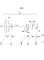
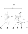
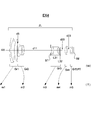
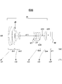
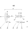
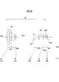
- FIGS. 1 to 10 are lens configuration diagrams respectively corresponding to the zoom lenses ZL constituting the first to tenth embodiments, and show the lens arrangement at the wide end (W) in an optical section.
- Arrows m1, m2, m3, and m4 in each lens configuration diagram indicate the first group Gr1, the second group Gr2, the third group Gr3, and the fourth group Gr4 in zooming from the wide end (W) to the tele end (T). Each movement is schematically shown.
- An arrow m5 closest to the image plane IM indicates that the position of the fifth lens group Gr5 and the plane parallel plate PT is fixed during zooming.
- An arrow mP closest to the image plane IM indicates that the plane parallel plate PT is zoomed. Indicates that the position is fixed.
- each group is configured as follows in a positive / negative / positive / positive five-group zoom configuration.
- the first group Gr1 includes, in order from the object side, a cemented lens including a negative meniscus lens concave on the image side and a positive meniscus lens convex on the object side, and a positive meniscus lens convex on the object side.
- the second group Gr2 includes, in order from the object side, a biconcave negative lens, and a cemented lens including a biconcave negative lens and a biconvex positive lens (image side surface is aspheric).
- the third lens unit Gr3 includes, in order from the object side, a stop lens ST, a cemented lens L31 including a positive meniscus lens convex on the object side (the object side is aspheric), a negative meniscus lens concave on the image side, and a biconvex positive lens. (First lens component) and a negative meniscus lens (double-sided aspheric surface) L32 (second lens component) concave on the object side.
- the fourth group Gr4 includes a cemented lens including a biconvex positive lens and a biconcave negative lens.
- the fifth group Gr5 is composed of only one biconvex positive lens (double-sided aspheric surface).
- each group is configured as follows in a positive / negative / positive / positive five-group zoom configuration.
- the first group Gr1 includes, in order from the object side, a cemented lens including a negative meniscus lens concave on the image side and a biconvex positive lens, and a positive meniscus lens convex on the object side.
- the second group Gr2 includes, in order from the object side, a negative meniscus lens that is concave on the image side, and a cemented lens that includes a biconcave negative lens and a biconvex positive lens.
- the third lens unit Gr3 includes, in order from the object side, the stop ST, a positive meniscus lens convex on the object side (object aspherical surface), a negative meniscus lens concave on the image side, and a positive meniscus lens convex on the object side. It is composed of a cemented lens L31 (first lens component) and a positive meniscus lens (double-sided aspheric surface) L32 (second lens component) convex on the image side.
- the fourth group Gr4 includes a cemented lens including a biconvex positive lens and a biconcave negative lens.
- the fifth group Gr5 is composed of only one positive meniscus lens (double-sided aspheric surface) convex toward the object side.
- each group is configured as follows in a positive / negative / positive / positive five-group zoom configuration.
- the first group Gr1 includes, in order from the object side, a cemented lens including a negative meniscus lens concave on the image side and a biconvex positive lens, and a positive meniscus lens convex on the object side.
- the second group Gr2 includes, in order from the object side, a negative meniscus lens that is concave on the image side, a cemented lens that includes a biconcave negative lens and a biconvex positive lens, and a negative meniscus lens that is concave on the object side (double-sided aspheric surface). ) And.
- the third lens unit Gr3 includes, in order from the object side, a stop lens ST, a cemented lens L31 (first lens) including a biconvex positive lens (object side is aspheric), a biconcave negative lens, and a positive meniscus lens convex on the object side. Lens component) and a positive meniscus lens (double-sided aspheric surface) L32 (second lens component) convex on the object side.
- the fourth group Gr4 includes a cemented lens including a biconvex positive lens and a biconcave negative lens.
- the fifth group Gr5 is composed of only one positive meniscus lens (double-sided aspheric surface) convex toward the object side.
- each group is configured as follows in a positive / negative / positive / positive five-group zoom configuration.
- the first group Gr1 includes, in order from the object side, a cemented lens including a negative meniscus lens concave on the image side and a biconvex positive lens, and a positive meniscus lens convex on the object side.
- the second group Gr2 includes, in order from the object side, a biconcave negative lens, and a cemented lens including a biconcave negative lens and a biconvex positive lens (image side surface is aspheric).
- the third lens unit Gr3 includes, in order from the object side, a stop lens ST, a cemented lens L31 (first lens) including a biconvex positive lens (object side is aspheric), a biconcave negative lens, and a positive meniscus lens convex on the object side. Lens component) and a biconvex positive lens (double-sided aspheric surface) L32 (second lens component).
- the fourth group Gr4 includes a cemented lens including a biconvex positive lens and a biconcave negative lens.
- the fifth group Gr5 is composed of only one positive meniscus lens (double-sided aspheric surface) convex toward the object side.
- each group is configured as follows in a positive / negative / positive four-group zoom configuration.
- the first group Gr1 includes, in order from the object side, a cemented lens including a negative meniscus lens concave on the image side and a positive meniscus lens convex on the object side, and a positive meniscus lens convex on the object side.
- the second group Gr2 includes, in order from the object side, a negative meniscus lens that is concave on the image side, and a cemented lens that includes a biconcave negative lens and a biconvex positive lens.
- the third lens unit Gr3 includes, in order from the object side, the stop ST, a positive meniscus lens convex on the object side (object aspherical surface), a negative meniscus lens concave on the image side, and a positive meniscus lens convex on the object side. It is composed of a cemented lens L31 (first lens component) and a biconvex positive lens (double-sided aspheric surface) L32 (second lens component).
- the fourth group Gr4 includes a cemented lens including a biconvex positive lens and a biconcave negative lens.
- each group is configured as follows in a positive / negative / positive / positive five-group zoom configuration.
- the first group Gr1 includes, in order from the object side, a cemented lens including a negative meniscus lens concave on the image side and a biconvex positive lens, and a positive meniscus lens convex on the object side.
- the second group Gr2 includes, in order from the object side, a biconcave negative lens, and a cemented lens including a biconcave negative lens and a biconvex positive lens (image side surface is aspheric).
- the third lens unit Gr3 includes, in order from the object side, a stop ST, a cemented lens including a biconvex positive lens (the object side surface is aspheric), a biconcave negative lens, and a positive meniscus lens convex on the object side, and a biconvex lens. Positive lens (double-sided aspherical surface).
- the fourth group Gr4 includes a cemented lens including a biconvex positive lens and a biconcave negative lens.
- the fifth group Gr5 is composed of only one biconvex positive lens (double-sided aspheric surface).
- each group is configured as follows in a positive / negative / positive / positive five-group zoom configuration.
- the first group Gr1 includes, in order from the object side, a cemented lens including a negative meniscus lens concave on the image side and a biconvex positive lens, and a positive meniscus lens convex on the object side.
- the second group Gr2 includes, in order from the object side, a negative meniscus lens that is concave on the image side, a cemented lens that includes a biconcave negative lens and a biconvex positive lens, and a negative meniscus lens that is concave on the object side (double-sided aspheric surface). ) And.
- the third lens unit Gr3 includes, in order from the object side, a stop ST, a cemented lens including a biconvex positive lens (the object side surface is aspheric), a biconcave negative lens, and a positive meniscus lens convex on the object side, and an object side. And a positive meniscus lens (double-sided aspherical surface).
- the fourth group Gr4 includes a cemented lens including a biconvex positive lens and a biconcave negative lens.
- the fifth group Gr5 is composed of only one positive meniscus lens (double-sided aspheric surface) convex toward the object side.
- each group is configured as follows in a positive / negative / positive / positive five-group zoom configuration.
- the first group Gr1 includes, in order from the object side, a cemented lens including a negative meniscus lens concave on the image side and a biconvex positive lens, and a positive meniscus lens convex on the object side.
- the second group Gr2 includes, in order from the object side, a negative meniscus lens concave on the image side, a biconcave negative lens (double-sided aspheric surface), and a biconvex positive lens.
- the third lens unit Gr3 includes, in order from the object side, the stop ST, a biconvex positive lens (double-sided aspheric surface), a negative meniscus lens concave on the image side, a negative meniscus lens concave on the image side, and a convex on the object side. And a cemented lens composed of a positive meniscus lens.
- the fourth group Gr4 includes a cemented lens including a biconvex positive lens and a biconcave negative lens.
- the fifth group Gr5 is composed of only one positive meniscus lens (double-sided aspheric surface) convex on the image side.
- each group is configured as follows in a positive / negative / positive / positive five-group zoom configuration.
- the first group Gr1 includes, in order from the object side, a cemented lens including a negative meniscus lens concave on the image side and a biconvex positive lens, and a positive meniscus lens convex on the object side.
- the second group Gr2 includes, in order from the object side, a biconcave negative lens, and a cemented lens including a biconcave negative lens (object side surface is aspheric) and a biconvex positive lens.
- the third lens unit Gr3 includes, in order from the object side, a stop ST, a cemented lens including a biconvex positive lens (the object side surface is aspheric) and a biconcave negative lens, a negative meniscus lens and a biconvex concave on the image side. And a cemented lens composed of a positive lens (image side surface is aspherical).
- the fourth group Gr4 includes a cemented lens including a biconvex positive lens and a biconcave negative lens.
- the fifth group Gr5 is composed of only one positive meniscus lens (double-sided aspheric surface) convex on the image side.
- each group is configured as follows in a positive / negative / positive four-group zoom configuration.
- the first group Gr1 includes, in order from the object side, a cemented lens including a negative meniscus lens concave on the image side and a biconvex positive lens, and a positive meniscus lens convex on the object side.
- the second group Gr2 includes, in order from the object side, a biconcave negative lens, and a cemented lens including a biconcave negative lens and a biconvex positive lens (image side surface is aspheric).
- the third lens unit Gr3 includes, in order from the object side, a stop ST, a cemented lens including a biconvex positive lens (the object side surface is aspheric), a biconcave negative lens, and a positive meniscus lens convex on the object side, and an object side. And a positive meniscus lens (double-sided aspherical surface).
- the fourth group Gr4 includes a cemented lens including a biconvex positive lens and a biconcave negative lens.
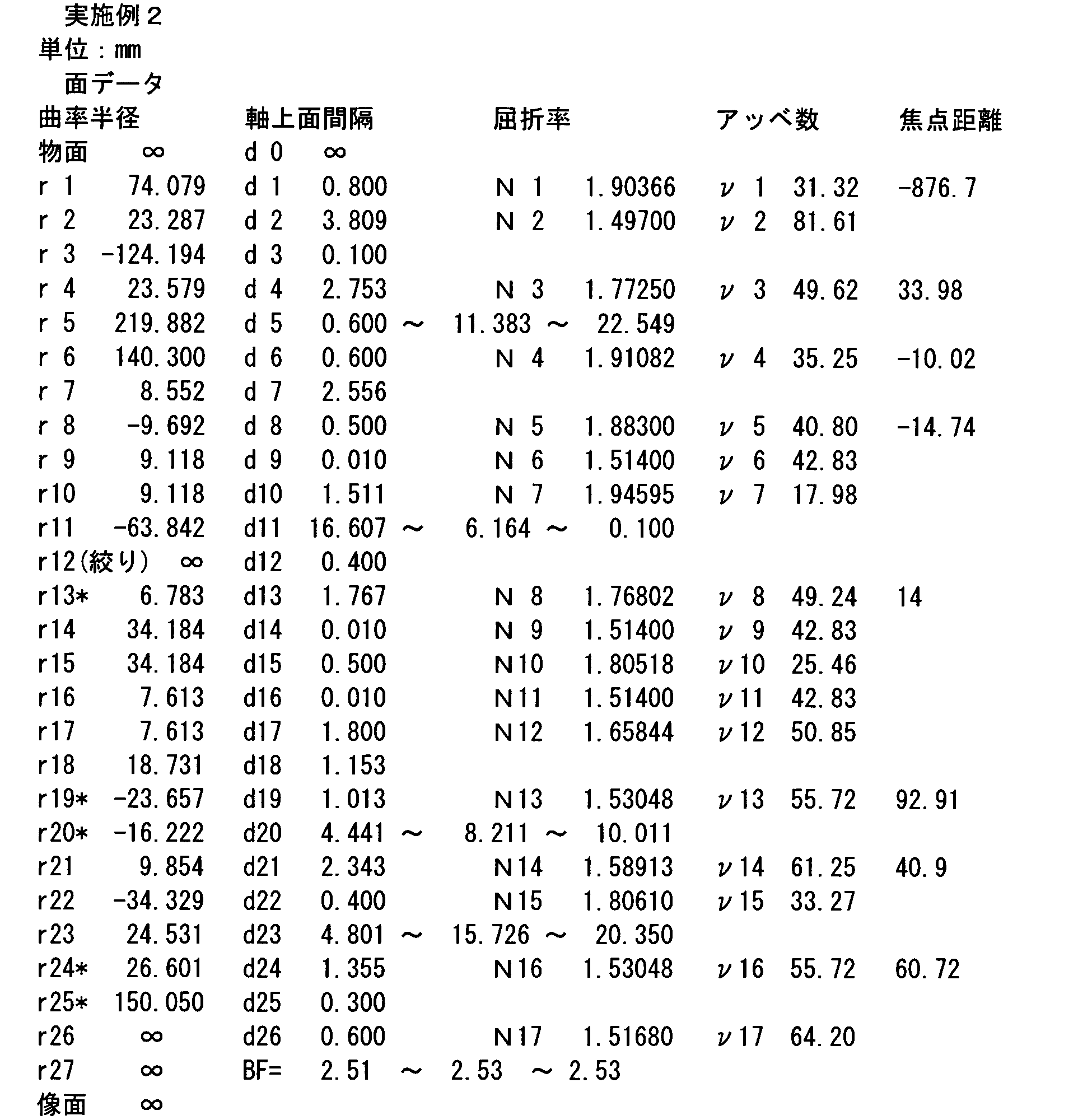
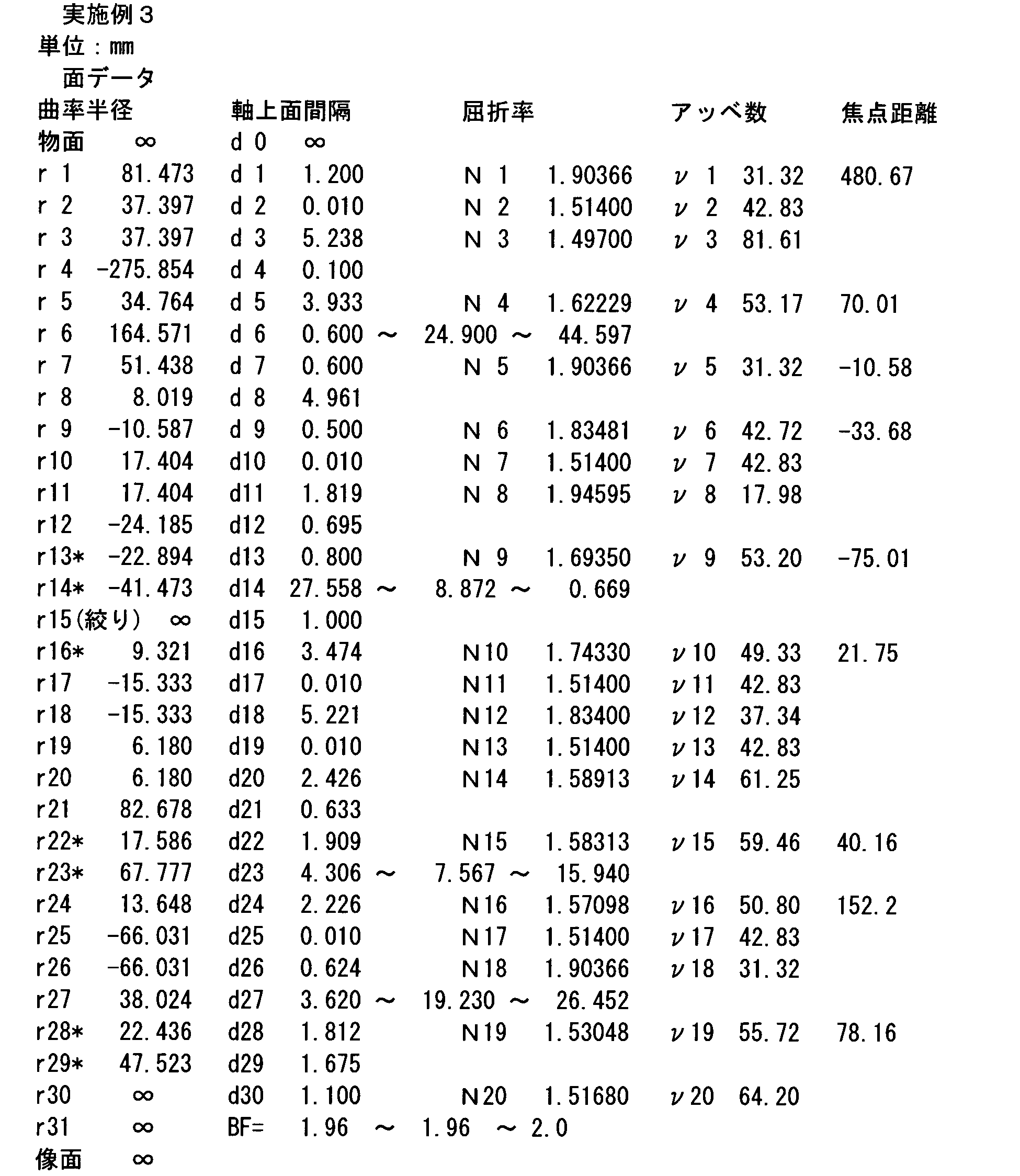
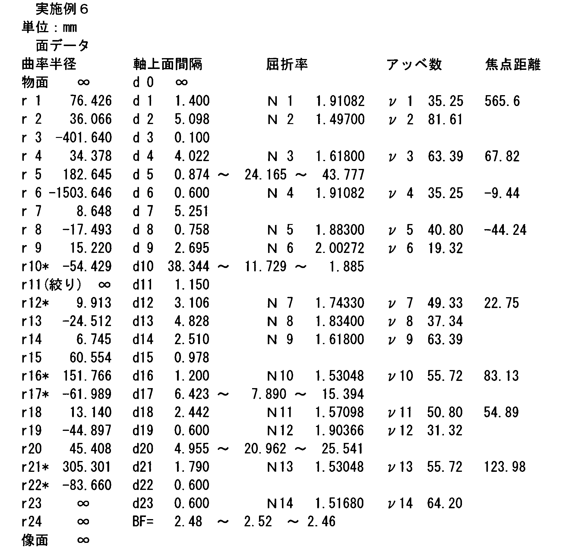
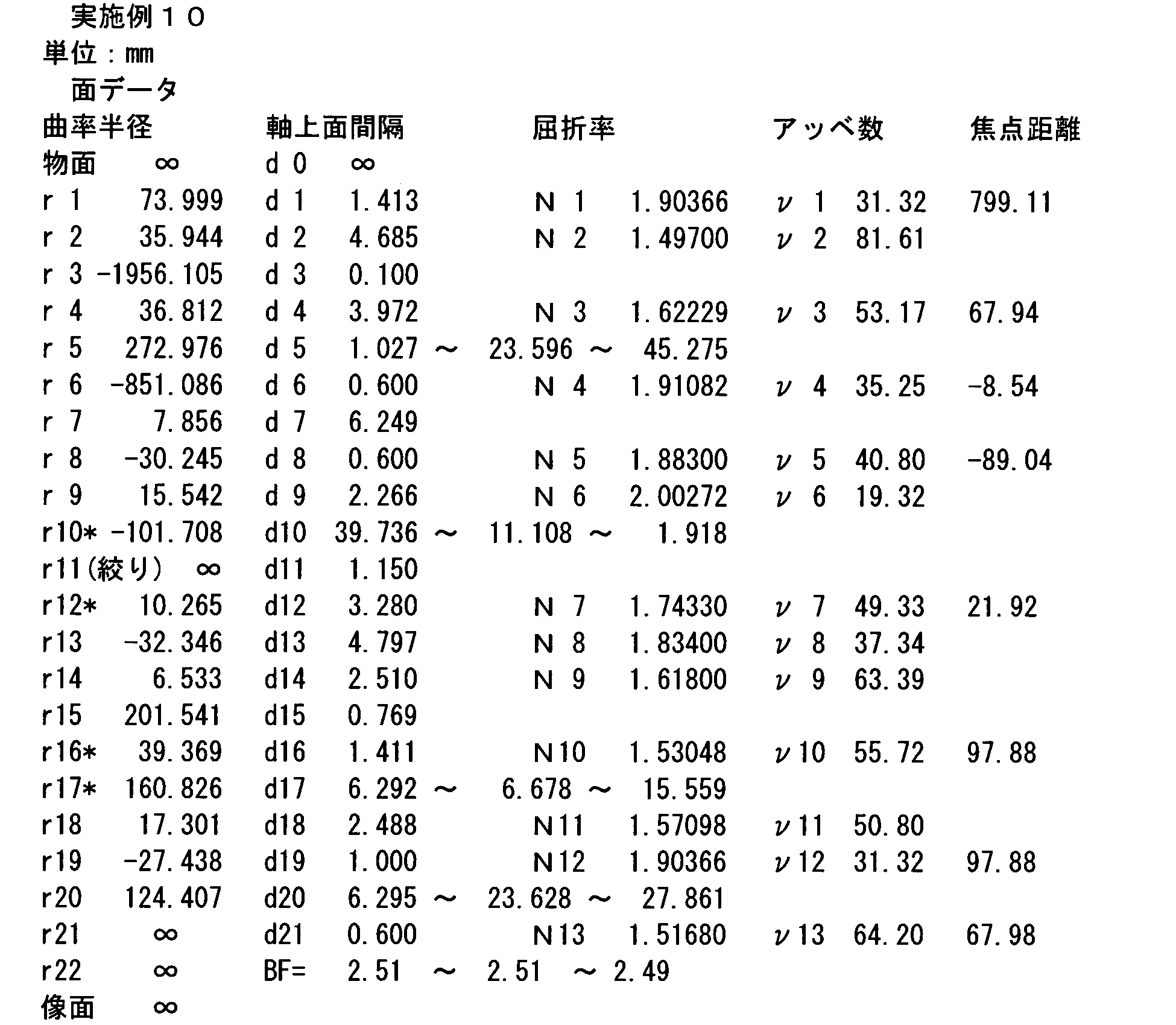
- Examples 1 to 10 (EX1 to 10) listed here are numerical examples corresponding to the first to tenth embodiments, respectively, and are optical configuration diagrams showing the first to tenth embodiments.
- FIGS. 1 to 10 show the lens configurations of the corresponding Examples 1 to 10, respectively.
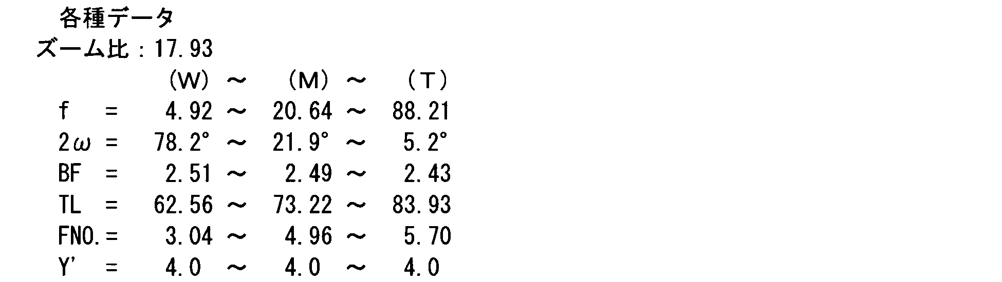
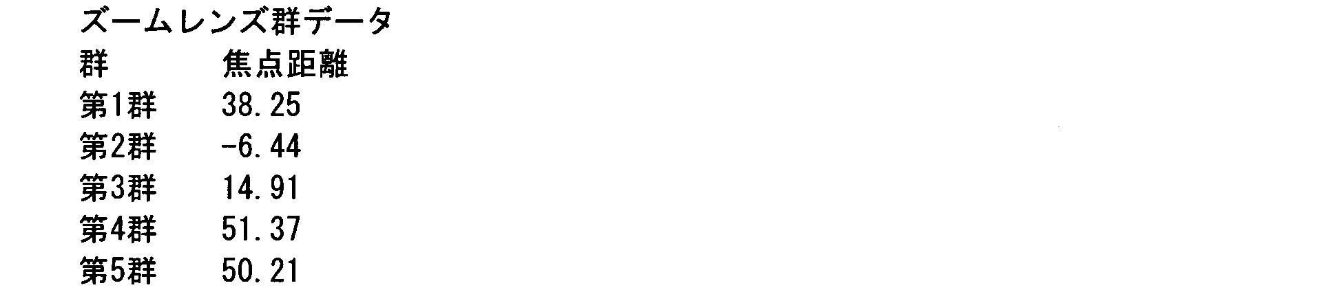
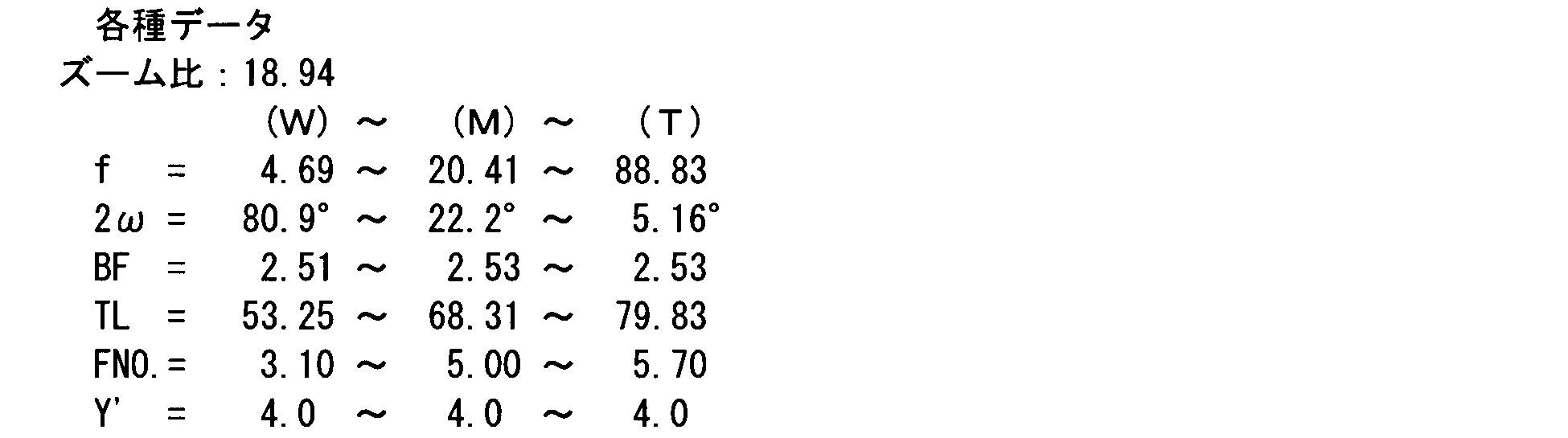
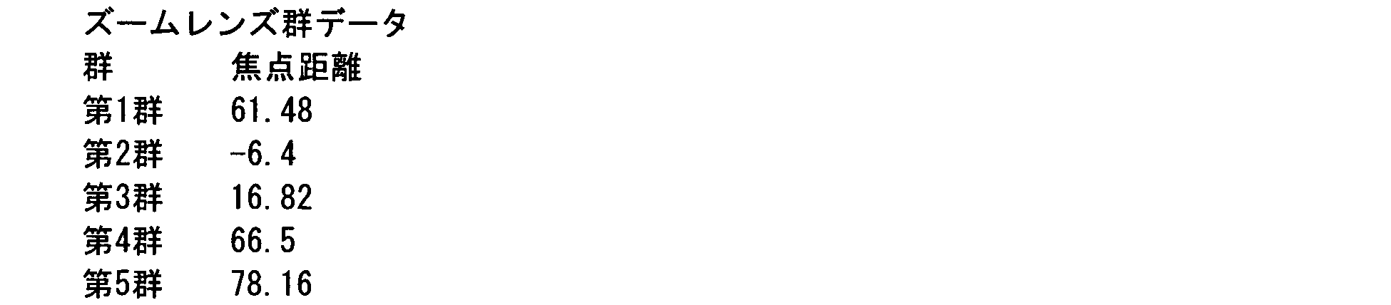
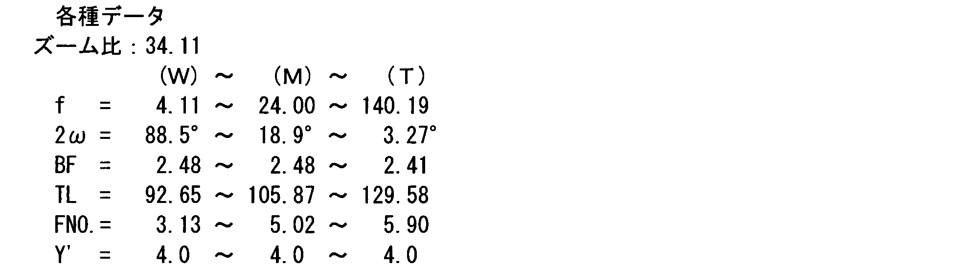
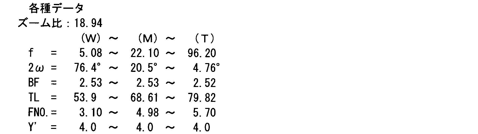
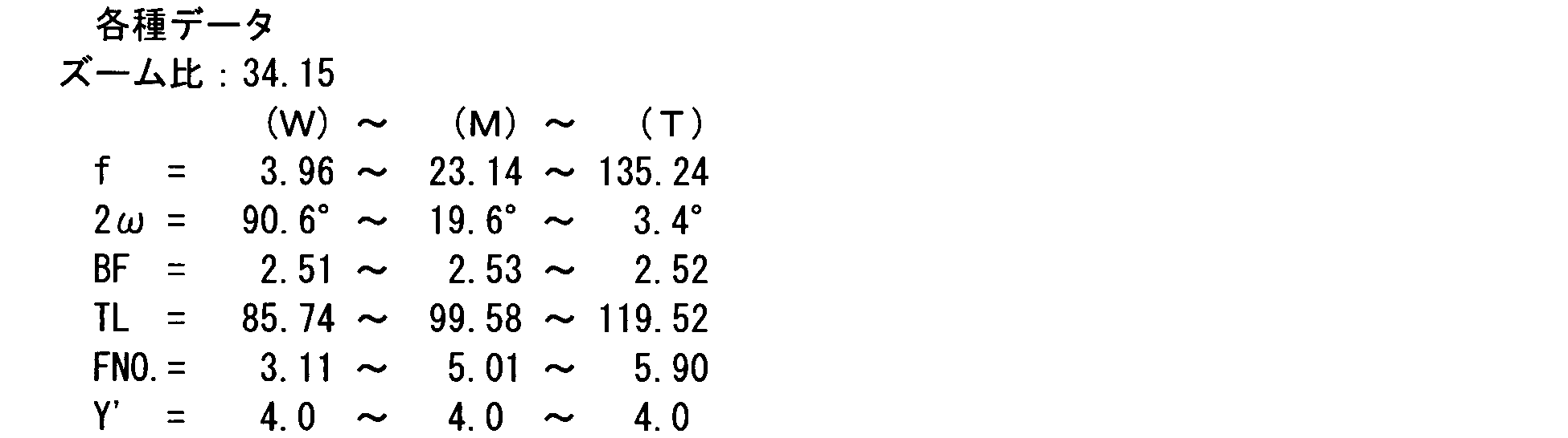
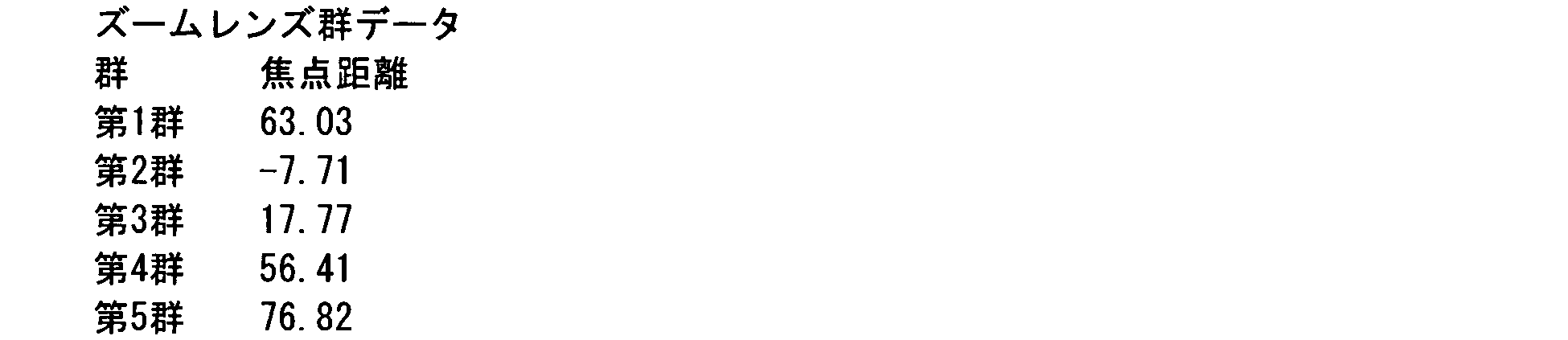
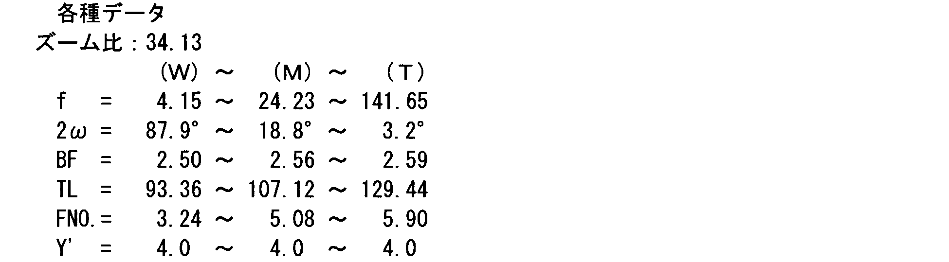
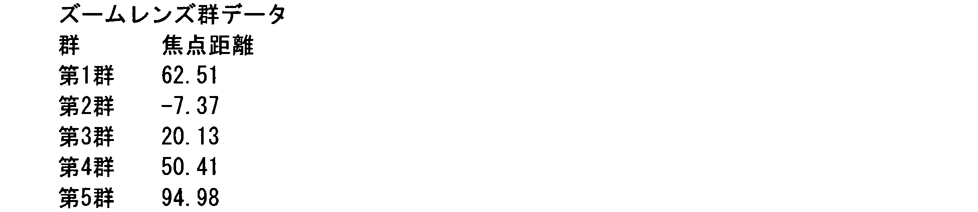
- zoom ratio, focal length (f, mm) of entire system, angle of view (2 ⁇ , °), back focus (BF, mm), total lens length (TL, mm), F number (Fno.), Image High (Y ′, mm) is indicated, and the focal length (mm) of each lens group is indicated as zoom lens group data.
- BF used here represents the distance from the image side surface of the cover glass (corresponding to the plane parallel plate PT) to the image surface.
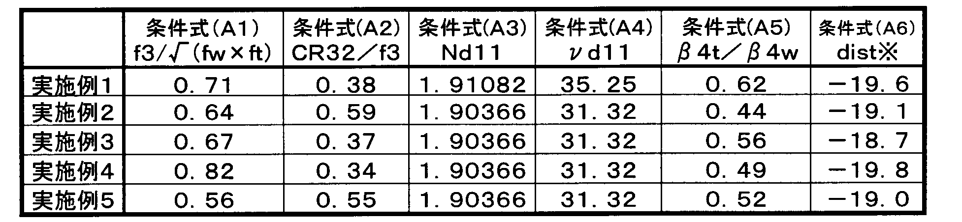
- Tables 1 and 2 show values corresponding to the conditional expressions of the respective examples.
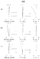
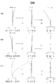
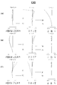
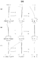
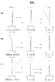
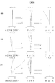
- FIGS. 11 to 20 are aberration diagrams respectively corresponding to Examples 1 to 10 (EX1 to EX10).
- W is a wide end
- M is an intermediate focal length state
- T is a tele end.
- FNO is the F number
- Y ′ (mm) is the maximum image height (corresponding to the distance from the optical axis AX) on the light receiving surface SS of the image sensor SR.
- a solid line d represents spherical aberration (mm) with respect to the d line
- a broken line SC represents an unsatisfactory sine condition (mm).
- the broken line DM represents the meridional surface
- the solid line DS represents each astigmatism (mm) with respect to the d-line on the sagittal surface.
- the solid line represents the distortion (%) with respect to the d-line.
- DU digital equipment LU imaging optical device ZL zoom lens Gr1 first group Gr2 second group Gr3 third group Gr4 fourth group Gr5 fifth group L31 first lens component (junction lens) L32 Second lens component ST Aperture (aperture stop) SR Image sensor SS Light-receiving surface (imaging surface) IM image plane (optical image) AX optical axis 1 signal processing unit 2 control unit 3 memory 4 operation unit 5 display unit
Landscapes
- Physics & Mathematics (AREA)
- General Physics & Mathematics (AREA)
- Optics & Photonics (AREA)
- Engineering & Computer Science (AREA)
- Multimedia (AREA)
- Signal Processing (AREA)
- Lenses (AREA)
- Nonlinear Science (AREA)
Abstract
Description
0.5<f3/√(fw×ft)<0.9 …(A1)
ただし、
f3:第3群の焦点距離、
fw:ワイド端における全系の焦点距離、
ft:テレ端における全系の焦点距離、
である。
0.3<CR32/f3<0.65 …(A2)
ただし、
CR32:接合レンズを構成している負レンズの像側面の曲率半径、
f3:第3群の焦点距離、
である。
1.86<Nd11<2 …(A3)
30<νd11<40 …(A4)
ただし、
Nd11:第1群を構成している負レンズのd線に関する屈折率、
νd11:第1群を構成している負レンズのd線に関するアッべ数、
である。
0.3<β4t/β4w<0.7 …(A5)
ただし、
β4t:テレ端での第4群の横倍率、
β4w:ワイド端での第4群の横倍率、
である。
-10<{(ywmax-Ymax)/Ymax}×100<-25 …(A6)
ただし、
ywmax:ワイド端での実像高の最大像高、
Ymax:理想像高の最大像高、
である。
7<β2t/β2w<10 …(B1)
5<β3t/β3w<12 …(B2)
0.7<(β2t/β2w)/(β3t/β3w)<1.65 …(B3)
ただし、
β2t:テレ端での第2群の横倍率、
β2w:ワイド端での第2群の横倍率、
β3t:テレ端での第3群の横倍率、
β3w:ワイド端での第3群の横倍率、
である。
1.86<Nd11<2 …(B4)
30<νd11<40 …(B5)
ただし、
Nd11:第1群を構成している負レンズのd線に関する屈折率、
νd11:第1群を構成している負レンズのd線に関するアッべ数、
である。
0.3<β4t/β4w<0.7 …(B6)
ただし、
β4t:テレ端での第4群の横倍率、
β4w:ワイド端での第4群の横倍率、
である。
-10<{(ywmax-Ymax)/Ymax}×100<-25 …(B7)
ただし、
ywmax:ワイド端での実像高の最大像高、
Ymax:理想像高の最大像高、
である。
-0.3<m3/TLt<-0.2 …(B8)
ただし、
m3:ワイド端からテレ端へズーミングする際の第3群の絶対的な移動量(符号は物体側への移動をマイナスとする。)、
TLt:テレ端での光学全長、
である。
-0.25<m4/TLt<-0.1 …(B9)
ただし、
m4:ワイド端からテレ端へズーミングする際の第4群の絶対的な移動量(符号は物体側への移動をマイナスとする。)、
TLt:テレ端での光学全長、
である。
0.5<f3/√(fw×ft)<0.9 …(A1)
ただし、
f3:第3群の焦点距離、
fw:ワイド端における全系の焦点距離、
ft:テレ端における全系の焦点距離、
である。
0.3<CR32/f3<0.65 …(A2)
ただし、
CR32:接合レンズを構成している負レンズの像側面の曲率半径、
f3:第3群の焦点距離、
である。
1.86<Nd11<2 …(A3)
30<νd11<40 …(A4)
ただし、
Nd11:第1群を構成している負レンズのd線に関する屈折率、
νd11:第1群を構成している負レンズのd線に関するアッべ数、
である。
0.3<β4t/β4w<0.7 …(A5)
ただし、
β4t:テレ端での第4群の横倍率、
β4w:ワイド端での第4群の横倍率、
である。
-10<{(ywmax-Ymax)/Ymax}×100<-25 …(A6)
ただし、
ywmax:ワイド端での実像高の最大像高、
Ymax:理想像高の最大像高、
である。
7<β2t/β2w<10 …(B1)
5<β3t/β3w<12 …(B2)
0.7<(β2t/β2w)/(β3t/β3w)<1.65 …(B3)
ただし、
β2t:テレ端での第2群の横倍率、
β2w:ワイド端での第2群の横倍率、
β3t:テレ端での第3群の横倍率、
β3w:ワイド端での第3群の横倍率、
である。
1.86<Nd11<2 …(B4)
30<νd11<40 …(B5)
ただし、
Nd11:第1群を構成している負レンズのd線に関する屈折率、
νd11:第1群を構成している負レンズのd線に関するアッべ数、
である。
0.3<β4t/β4w<0.7 …(B6)
ただし、
β4t:テレ端での第4群の横倍率、
β4w:ワイド端での第4群の横倍率、
である。
-10<{(ywmax-Ymax)/Ymax}×100<-25 …(B7)
ただし、
ywmax:ワイド端での実像高の最大像高、
Ymax:理想像高の最大像高、
である。
-0.3<m3/TLt<-0.2 …(B8)
ただし、
m3:ワイド端からテレ端へズーミングする際の第3群の絶対的な移動量(符号は物体側への移動をマイナスとする。)、
TLt:テレ端での光学全長、
である。
-0.25<m4/TLt<-0.1 …(B9)
ただし、
m4:ワイド端からテレ端へズーミングする際の第4群の絶対的な移動量(符号は物体側への移動をマイナスとする。)、
TLt:テレ端での光学全長、
である。
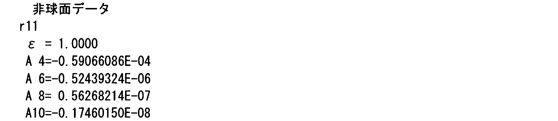
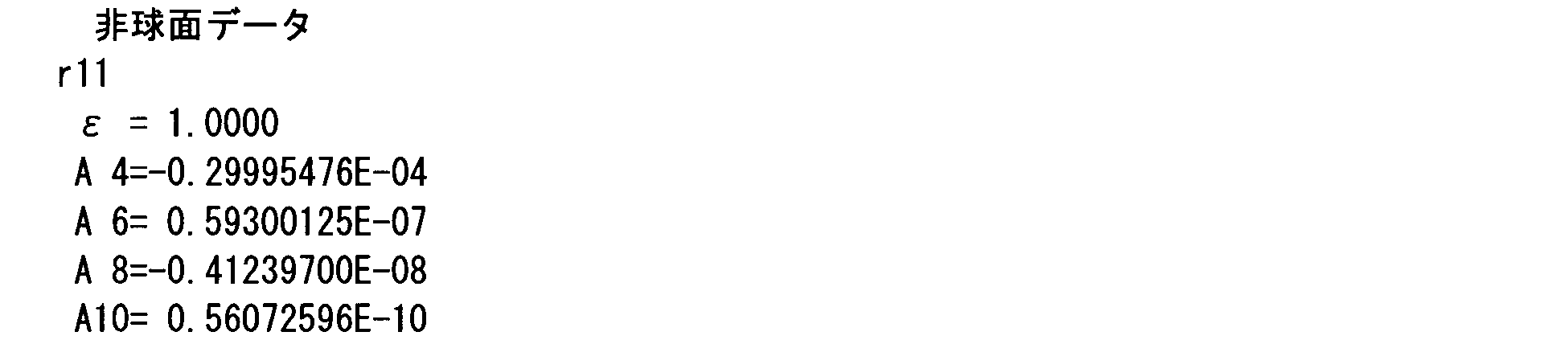
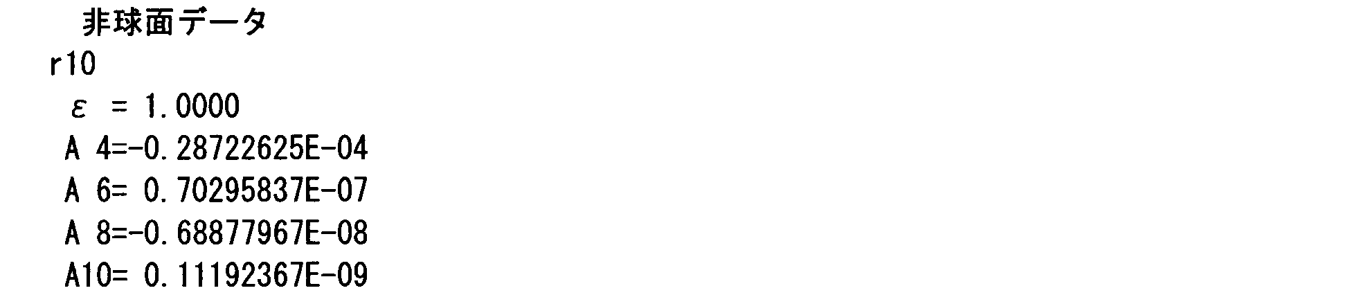
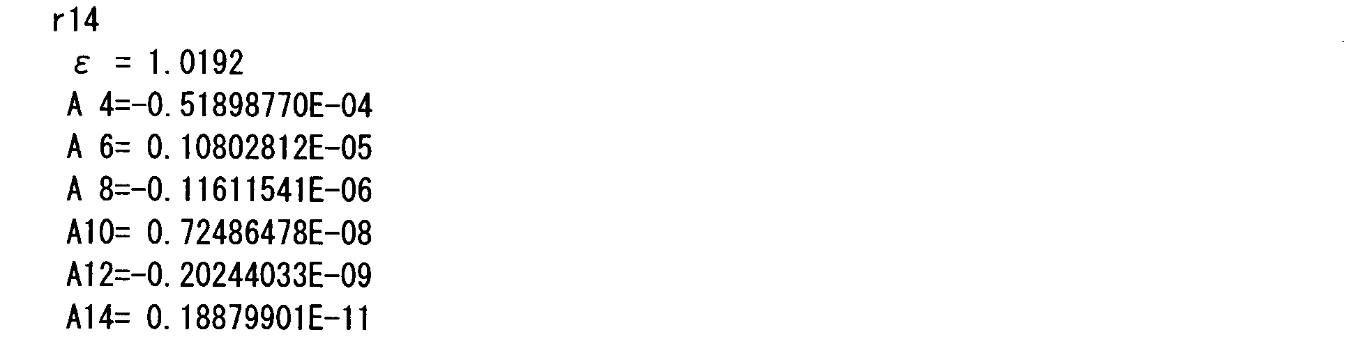
z=(c・h2)/{1+√(1-ε・c2・h2)}+Σ(Aj・hj) …(AS)
ただし、
h:z軸(光軸AX)に対して垂直な方向の高さ(h2=x2+y2)、
z:高さhの位置での光軸AX方向のサグ量(面頂点基準)、
c:面頂点での曲率(曲率半径rの逆数)、
ε:2次曲面パラメータ、
Aj:j次の非球面係数、
である。












































LU 撮像光学装置
ZL ズームレンズ
Gr1 第1群
Gr2 第2群
Gr3 第3群
Gr4 第4群
Gr5 第5群
L31 第1レンズ成分(接合レンズ)
L32 第2レンズ成分
ST 絞り(開口絞り)
SR 撮像素子
SS 受光面(撮像面)
IM 像面(光学像)
AX 光軸
1 信号処理部
2 制御部
3 メモリ
4 操作部
5 表示部
Claims (18)
- 物体側から順に、正パワーを有する第1群と、負パワーを有する第2群と、正パワーを有する第3群と、正パワーを有する第4群と、を含み、前記第1群から前記第4群がそれぞれ移動して各群間隔を変化させることにより変倍を行うズームレンズであって、
前記第3群が少なくとも一方に非球面を有する2つのレンズ成分から成り、そのうちの物体側のレンズ成分が、物体側から順に、正レンズ,負レンズ及び正レンズから成る接合レンズであることを特徴とするズームレンズ。 - 前記第3群が以下の条件式(A1)を満たすことを特徴とする請求項1記載のズームレンズ;
0.5<f3/√(fw×ft)<0.9 …(A1)
ただし、
f3:第3群の焦点距離、
fw:ワイド端における全系の焦点距離、
ft:テレ端における全系の焦点距離、
である。 - 前記第3群が以下の条件式(A2)を満たすことを特徴とする請求項1又は2記載のズームレンズ;
0.3<CR32/f3<0.65 …(A2)
ただし、
CR32:接合レンズを構成している負レンズの像側面の曲率半径、
f3:第3群の焦点距離、
である。 - 前記接合レンズを構成している最物体側の正レンズが非球面を有し、その非球面は光軸を離れるほど曲率半径が参照曲率半径に対し大きくなることを特徴とする請求項1~3のいずれか1項に記載のズームレンズ。
- 前記第1群が、物体側から順に、負レンズ及び正レンズから成る接合レンズと、正の単レンズと、で構成され、以下の条件式(A3)及び(A4)を満たすことを特徴とする請求項1~4のいずれか1項に記載のズームレンズ;
1.86<Nd11<2 …(A3)
30<νd11<40 …(A4)
ただし、
Nd11:第1群を構成している負レンズのd線に関する屈折率、
νd11:第1群を構成している負レンズのd線に関するアッべ数、
である。 - 以下の条件式(A5)を満たすことを特徴とする請求項1~5のいずれか1項に記載のズームレンズ;
0.3<β4t/β4w<0.7 …(A5)
ただし、
β4t:テレ端での第4群の横倍率、
β4w:ワイド端での第4群の横倍率、
である。 - 以下の条件式(A6)を満たすことを特徴とする請求項1~6のいずれか1項に記載のズームレンズ;
-10<{(ywmax-Ymax)/Ymax}×100<-25 …(A6)
ただし、
ywmax:ワイド端での実像高の最大像高、
Ymax:理想像高の最大像高、
である。 - 物体側から順に、正パワーを有する第1群と、負パワーを有する第2群と、正パワーを有する第3群と、正パワーを有する第4群と、を含み、前記第1群から前記第4群がそれぞれ移動して各群間隔を変化させることにより変倍を行うズームレンズであって、以下の条件式(B1)~(B3)を満たすことを特徴とするズームレンズ;
7<β2t/β2w<10 …(B1)
5<β3t/β3w<12 …(B2)
0.7<(β2t/β2w)/(β3t/β3w)<1.65 …(B3)
ただし、
β2t:テレ端での第2群の横倍率、
β2w:ワイド端での第2群の横倍率、
β3t:テレ端での第3群の横倍率、
β3w:ワイド端での第3群の横倍率、
である。 - 前記第1群が、物体側から順に、負レンズ及び正レンズから成る接合レンズと、正の単レンズと、で構成され、以下の条件式(B4)及び(B5)を満たすことを特徴とする請求項8記載のズームレンズ;
1.86<Nd11<2 …(B4)
30<νd11<40 …(B5)
ただし、
Nd11:第1群を構成している負レンズのd線に関する屈折率、
νd11:第1群を構成している負レンズのd線に関するアッべ数、
である。 - 以下の条件式(B6)を満たすことを特徴とする請求項8又は9記載のズームレンズ;
0.3<β4t/β4w<0.7 …(B6)
ただし、
β4t:テレ端での第4群の横倍率、
β4w:ワイド端での第4群の横倍率、
である。 - 以下の条件式(B7)を満たすことを特徴とする請求項8~10のいずれか1項に記載のズームレンズ;
-10<{(ywmax-Ymax)/Ymax}×100<-25 …(B7)
ただし、
ywmax:ワイド端での実像高の最大像高、
Ymax:理想像高の最大像高、
である。 - 前記第3群の最物体側面が非球面で構成されていることを特徴とする請求項8~11のいずれか1項に記載のズームレンズ。
- 前記第2群が、物体側から順に、物体側に凸面を向けた負メニスカスレンズと、両凹の負レンズ及び両凸の正レンズから成る接合レンズと、像側に凸面を向けた負メニスカスレンズと、で構成されていることを特徴とする請求項8~12のいずれか1項に記載のズームレンズ。
- 以下の条件式(B8)を満たすことを特徴とする請求項8~13のいずれか1項に記載のズームレンズ;
-0.3<m3/TLt<-0.2 …(B8)
ただし、
m3:ワイド端からテレ端へズーミングする際の第3群の絶対的な移動量(符号は物体側への移動をマイナスとする。)、
TLt:テレ端での光学全長、
である。 - 以下の条件式(B9)を満たすことを特徴とする請求項8~14のいずれか1項に記載のズームレンズ;
-0.25<m4/TLt<-0.1 …(B9)
ただし、
m4:ワイド端からテレ端へズーミングする際の第4群の絶対的な移動量(符号は物体側への移動をマイナスとする。)、
TLt:テレ端での光学全長、
である。 - 請求項1~15のいずれか1項に記載のズームレンズと、受光面上に形成された光学像を電気的な信号に変換する撮像素子と、を備え、前記撮像素子の受光面上に被写体の光学像が形成されるように前記ズームレンズが設けられていることを特徴とする撮像光学装置。
- 請求項16記載の撮像光学装置を備えることにより、被写体の静止画撮影,動画撮影のうちの少なくとも一方の機能が付加されたことを特徴とするデジタル機器。
- デジタルカメラ,監視カメラ又は画像入力機能付き携帯端末であることを特徴とする請求項17記載のデジタル機器。
Priority Applications (2)
| Application Number | Priority Date | Filing Date | Title |
|---|---|---|---|
| US13/980,758 US9304303B2 (en) | 2011-01-24 | 2012-01-16 | Zoom lens system, imaging optical device, and digital apparatus |
| JP2012554725A JP5609994B2 (ja) | 2011-01-24 | 2012-01-16 | ズームレンズ,撮像光学装置及びデジタル機器 |
Applications Claiming Priority (4)
| Application Number | Priority Date | Filing Date | Title |
|---|---|---|---|
| JP2011-011807 | 2011-01-24 | ||
| JP2011011794 | 2011-01-24 | ||
| JP2011-011794 | 2011-01-24 | ||
| JP2011011807 | 2011-01-24 |
Publications (1)
| Publication Number | Publication Date |
|---|---|
| WO2012102105A1 true WO2012102105A1 (ja) | 2012-08-02 |
Family
ID=46580677
Family Applications (1)
| Application Number | Title | Priority Date | Filing Date |
|---|---|---|---|
| PCT/JP2012/050663 Ceased WO2012102105A1 (ja) | 2011-01-24 | 2012-01-16 | ズームレンズ,撮像光学装置及びデジタル機器 |
Country Status (3)
| Country | Link |
|---|---|
| US (1) | US9304303B2 (ja) |
| JP (1) | JP5609994B2 (ja) |
| WO (1) | WO2012102105A1 (ja) |
Cited By (15)
| Publication number | Priority date | Publication date | Assignee | Title |
|---|---|---|---|---|
| JP2013164455A (ja) * | 2012-02-09 | 2013-08-22 | Canon Inc | ズームレンズ及びそれを有する撮像装置 |
| JP2013250340A (ja) * | 2012-05-30 | 2013-12-12 | Canon Inc | ズームレンズ及びそれを有する撮像装置 |
| JP2014089289A (ja) * | 2012-10-30 | 2014-05-15 | Nikon Corp | 変倍光学系、光学装置、変倍光学系の製造方法 |
| JP2014089283A (ja) * | 2012-10-30 | 2014-05-15 | Nikon Corp | 変倍光学系、光学装置、変倍光学系の製造方法 |
| JP2014089285A (ja) * | 2012-10-30 | 2014-05-15 | Nikon Corp | 変倍光学系、光学装置、変倍光学系の製造方法 |
| JP2014089288A (ja) * | 2012-10-30 | 2014-05-15 | Nikon Corp | 変倍光学系、光学装置、変倍光学系の製造方法 |
| JP2014089284A (ja) * | 2012-10-30 | 2014-05-15 | Nikon Corp | 変倍光学系、光学装置、変倍光学系の製造方法 |
| JP2014211521A (ja) * | 2013-04-18 | 2014-11-13 | キヤノン株式会社 | ズームレンズ及びそれを有する撮像装置 |
| CN104730683A (zh) * | 2013-12-18 | 2015-06-24 | 株式会社腾龙 | 变焦镜头及摄像装置 |
| CN104755985A (zh) * | 2012-10-30 | 2015-07-01 | 株式会社尼康 | 变倍光学系统、光学装置,和用于变倍光学系统的生产方法 |
| JP2015121736A (ja) * | 2013-12-25 | 2015-07-02 | キヤノン株式会社 | ズームレンズおよびこれを用いた撮像装置 |
| US9453993B2 (en) | 2012-10-30 | 2016-09-27 | Nikon Corporation | Variable magnification optical system, optical device, and production method for variable magnification optical system |
| US9874730B2 (en) | 2012-10-30 | 2018-01-23 | Nikon Corporation | Variable magnification optical system, optical device, and production method for variable magnification optical system |
| JP2022018006A (ja) * | 2020-07-14 | 2022-01-26 | キヤノン株式会社 | ズームレンズおよび撮像装置 |
| US12546973B2 (en) | 2021-09-03 | 2026-02-10 | Canon Kabushiki Kaisha | Optical system, image pickup apparatus, in-vehicle system, and moving apparatus |
Families Citing this family (8)
| Publication number | Priority date | Publication date | Assignee | Title |
|---|---|---|---|---|
| JP5919840B2 (ja) * | 2012-01-25 | 2016-05-18 | 株式会社ニコン | ズームレンズ及び光学機器 |
| JP5724932B2 (ja) * | 2012-04-06 | 2015-05-27 | コニカミノルタ株式会社 | レーザ走査光学系 |
| WO2016129056A1 (ja) * | 2015-02-10 | 2016-08-18 | オリンパス株式会社 | ズーム撮像装置 |
| WO2016129054A1 (ja) * | 2015-02-10 | 2016-08-18 | オリンパス株式会社 | ズーム撮像装置 |
| US10012827B1 (en) | 2015-05-14 | 2018-07-03 | Lockheed Martin Corporation | Segmented planar imaging detector for electro-optic reconnaissance (SPIDER) zoom |
| US10606046B2 (en) * | 2015-07-20 | 2020-03-31 | Young Optics Inc. | Zoom lens |
| CN117355781A (zh) * | 2022-05-05 | 2024-01-05 | 北京小米移动软件有限公司 | 光学系统、以及具备光学系统的拍摄装置 |
| CN114815196B (zh) * | 2022-06-06 | 2024-02-23 | 舜宇光学(中山)有限公司 | 变焦镜头 |
Citations (3)
| Publication number | Priority date | Publication date | Assignee | Title |
|---|---|---|---|---|
| JP2005308998A (ja) * | 2004-04-20 | 2005-11-04 | Sony Corp | ズームレンズ及び撮像装置 |
| JP2006184416A (ja) * | 2004-12-27 | 2006-07-13 | Konica Minolta Photo Imaging Inc | 撮影光学系および撮像装置 |
| JP2007256604A (ja) * | 2006-03-23 | 2007-10-04 | Olympus Imaging Corp | ズームレンズ及びそれを有する撮像装置 |
Family Cites Families (5)
| Publication number | Priority date | Publication date | Assignee | Title |
|---|---|---|---|---|
| JP4806976B2 (ja) | 2005-06-21 | 2011-11-02 | コニカミノルタオプト株式会社 | 変倍光学系 |
| US7764439B2 (en) | 2006-03-22 | 2010-07-27 | Olympus Imaging Corp. | Zoom lens system and image pickup apparatus using the same |
| JP4296520B2 (ja) | 2006-12-21 | 2009-07-15 | ソニー株式会社 | ズームレンズ及び撮像装置 |
| JP5433942B2 (ja) * | 2007-11-22 | 2014-03-05 | 株式会社ニコン | ズームレンズ、これを搭載する光学機器および結像方法 |
| JP5178322B2 (ja) | 2008-05-26 | 2013-04-10 | キヤノン株式会社 | ズームレンズ及びそれを有する撮像装置 |
-
2012
- 2012-01-16 WO PCT/JP2012/050663 patent/WO2012102105A1/ja not_active Ceased
- 2012-01-16 JP JP2012554725A patent/JP5609994B2/ja not_active Expired - Fee Related
- 2012-01-16 US US13/980,758 patent/US9304303B2/en not_active Expired - Fee Related
Patent Citations (3)
| Publication number | Priority date | Publication date | Assignee | Title |
|---|---|---|---|---|
| JP2005308998A (ja) * | 2004-04-20 | 2005-11-04 | Sony Corp | ズームレンズ及び撮像装置 |
| JP2006184416A (ja) * | 2004-12-27 | 2006-07-13 | Konica Minolta Photo Imaging Inc | 撮影光学系および撮像装置 |
| JP2007256604A (ja) * | 2006-03-23 | 2007-10-04 | Olympus Imaging Corp | ズームレンズ及びそれを有する撮像装置 |
Cited By (21)
| Publication number | Priority date | Publication date | Assignee | Title |
|---|---|---|---|---|
| JP2013164455A (ja) * | 2012-02-09 | 2013-08-22 | Canon Inc | ズームレンズ及びそれを有する撮像装置 |
| JP2013250340A (ja) * | 2012-05-30 | 2013-12-12 | Canon Inc | ズームレンズ及びそれを有する撮像装置 |
| CN104755985B (zh) * | 2012-10-30 | 2018-07-31 | 株式会社尼康 | 变倍光学系统和光学装置 |
| JP2014089289A (ja) * | 2012-10-30 | 2014-05-15 | Nikon Corp | 変倍光学系、光学装置、変倍光学系の製造方法 |
| JP2014089285A (ja) * | 2012-10-30 | 2014-05-15 | Nikon Corp | 変倍光学系、光学装置、変倍光学系の製造方法 |
| JP2014089288A (ja) * | 2012-10-30 | 2014-05-15 | Nikon Corp | 変倍光学系、光学装置、変倍光学系の製造方法 |
| JP2014089284A (ja) * | 2012-10-30 | 2014-05-15 | Nikon Corp | 変倍光学系、光学装置、変倍光学系の製造方法 |
| US10126535B2 (en) | 2012-10-30 | 2018-11-13 | Nikon Corporation | Variable magnification optical system, optical device, and production method for variable magnification optical system |
| JP2014089283A (ja) * | 2012-10-30 | 2014-05-15 | Nikon Corp | 変倍光学系、光学装置、変倍光学系の製造方法 |
| CN104755985A (zh) * | 2012-10-30 | 2015-07-01 | 株式会社尼康 | 变倍光学系统、光学装置,和用于变倍光学系统的生产方法 |
| US9874730B2 (en) | 2012-10-30 | 2018-01-23 | Nikon Corporation | Variable magnification optical system, optical device, and production method for variable magnification optical system |
| US9453993B2 (en) | 2012-10-30 | 2016-09-27 | Nikon Corporation | Variable magnification optical system, optical device, and production method for variable magnification optical system |
| EP2916156A4 (en) * | 2012-10-30 | 2016-10-05 | Nikon Corp | OPTICAL SYSTEM WITH VARIABLE MAGNIFICATION, OPTICAL DEVICE AND MANUFACTURING METHOD FOR AN OPTICAL SYSTEM WITH VARIABLE MAGNIFICATION |
| JP2014211521A (ja) * | 2013-04-18 | 2014-11-13 | キヤノン株式会社 | ズームレンズ及びそれを有する撮像装置 |
| CN104730683B (zh) * | 2013-12-18 | 2017-05-03 | 株式会社腾龙 | 变焦镜头及摄像装置 |
| CN104730683A (zh) * | 2013-12-18 | 2015-06-24 | 株式会社腾龙 | 变焦镜头及摄像装置 |
| JP2015121736A (ja) * | 2013-12-25 | 2015-07-02 | キヤノン株式会社 | ズームレンズおよびこれを用いた撮像装置 |
| JP2022018006A (ja) * | 2020-07-14 | 2022-01-26 | キヤノン株式会社 | ズームレンズおよび撮像装置 |
| US11960066B2 (en) | 2020-07-14 | 2024-04-16 | Canon Kabushiki Kaisha | Zoom lens and image pickup apparatus |
| JP7625377B2 (ja) | 2020-07-14 | 2025-02-03 | キヤノン株式会社 | ズームレンズおよび撮像装置 |
| US12546973B2 (en) | 2021-09-03 | 2026-02-10 | Canon Kabushiki Kaisha | Optical system, image pickup apparatus, in-vehicle system, and moving apparatus |
Also Published As
| Publication number | Publication date |
|---|---|
| US20130300868A1 (en) | 2013-11-14 |
| JPWO2012102105A1 (ja) | 2014-06-30 |
| JP5609994B2 (ja) | 2014-10-22 |
| US9304303B2 (en) | 2016-04-05 |
Similar Documents
| Publication | Publication Date | Title |
|---|---|---|
| JP5609994B2 (ja) | ズームレンズ,撮像光学装置及びデジタル機器 | |
| JP5585719B2 (ja) | ズームレンズ,撮像光学装置及びデジタル機器 | |
| JP4867383B2 (ja) | 変倍光学系 | |
| JP5023820B2 (ja) | 防振機能を有するズームレンズ及び撮像装置 | |
| JP4259495B2 (ja) | 変倍光学系 | |
| JP5045266B2 (ja) | ズームレンズ及び撮像装置 | |
| JP5699967B2 (ja) | ズームレンズ,撮像光学装置及びデジタル機器 | |
| JP5821968B2 (ja) | 変倍光学系 | |
| US20050200968A1 (en) | Image-taking apparatus | |
| JP2004170707A (ja) | 撮像レンズ装置およびそれを備えたデジタルカメラ | |
| JP5928426B2 (ja) | 変倍光学系,撮像光学装置及びデジタル機器 | |
| JP4806976B2 (ja) | 変倍光学系 | |
| JP5699950B2 (ja) | ズームレンズ,撮像光学装置及びデジタル機器 | |
| EP3327480B1 (en) | Zoom lens system, imaging optical device, and digital apparatus | |
| JP2007148052A (ja) | 変倍光学系 | |
| JP5928428B2 (ja) | 変倍光学系,撮像光学装置及びデジタル機器 | |
| WO2014010504A1 (ja) | ズームレンズ,撮像光学装置及びデジタル機器 | |
| JP2006039180A (ja) | 撮像装置 | |
| JP2005258057A (ja) | 撮像装置 | |
| JP2006317478A (ja) | 変倍光学系 | |
| JP2006195071A (ja) | 変倍光学系 | |
| JP2014238549A (ja) | 変倍光学系,撮像光学装置及びデジタル機器 | |
| JP5445102B2 (ja) | ズームレンズ,撮像光学装置及びデジタル機器 | |
| JP4992102B2 (ja) | 変倍光学系及び撮像装置 | |
| WO2012117857A1 (ja) | ズームレンズ,撮像光学装置及びデジタル機器 |
Legal Events
| Date | Code | Title | Description |
|---|---|---|---|
| 121 | Ep: the epo has been informed by wipo that ep was designated in this application |
Ref document number: 12739600 Country of ref document: EP Kind code of ref document: A1 |
|
| ENP | Entry into the national phase |
Ref document number: 2012554725 Country of ref document: JP Kind code of ref document: A |
|
| WWE | Wipo information: entry into national phase |
Ref document number: 13980758 Country of ref document: US |
|
| NENP | Non-entry into the national phase |
Ref country code: DE |
|
| 122 | Ep: pct application non-entry in european phase |
Ref document number: 12739600 Country of ref document: EP Kind code of ref document: A1 |