WO2012102088A1 - 画像復号装置と画像符号化装置およびその方法 - Google Patents
画像復号装置と画像符号化装置およびその方法 Download PDFInfo
- Publication number
- WO2012102088A1 WO2012102088A1 PCT/JP2012/050456 JP2012050456W WO2012102088A1 WO 2012102088 A1 WO2012102088 A1 WO 2012102088A1 JP 2012050456 W JP2012050456 W JP 2012050456W WO 2012102088 A1 WO2012102088 A1 WO 2012102088A1
- Authority
- WO
- WIPO (PCT)
- Prior art keywords
- quantization parameter
- unit
- image
- information
- block
- Prior art date
Links
Images


Classifications
-
- H—ELECTRICITY
- H04—ELECTRIC COMMUNICATION TECHNIQUE
- H04N—PICTORIAL COMMUNICATION, e.g. TELEVISION
- H04N19/00—Methods or arrangements for coding, decoding, compressing or decompressing digital video signals
- H04N19/10—Methods or arrangements for coding, decoding, compressing or decompressing digital video signals using adaptive coding
- H04N19/102—Methods or arrangements for coding, decoding, compressing or decompressing digital video signals using adaptive coding characterised by the element, parameter or selection affected or controlled by the adaptive coding
- H04N19/124—Quantisation
- H04N19/126—Details of normalisation or weighting functions, e.g. normalisation matrices or variable uniform quantisers
-
- G—PHYSICS
- G06—COMPUTING OR CALCULATING; COUNTING
- G06T—IMAGE DATA PROCESSING OR GENERATION, IN GENERAL
- G06T9/00—Image coding
-
- G—PHYSICS
- G06—COMPUTING OR CALCULATING; COUNTING
- G06T—IMAGE DATA PROCESSING OR GENERATION, IN GENERAL
- G06T9/00—Image coding
- G06T9/008—Vector quantisation
-
- H—ELECTRICITY
- H04—ELECTRIC COMMUNICATION TECHNIQUE
- H04N—PICTORIAL COMMUNICATION, e.g. TELEVISION
- H04N19/00—Methods or arrangements for coding, decoding, compressing or decompressing digital video signals
- H04N19/10—Methods or arrangements for coding, decoding, compressing or decompressing digital video signals using adaptive coding
- H04N19/102—Methods or arrangements for coding, decoding, compressing or decompressing digital video signals using adaptive coding characterised by the element, parameter or selection affected or controlled by the adaptive coding
- H04N19/124—Quantisation
-
- H—ELECTRICITY
- H04—ELECTRIC COMMUNICATION TECHNIQUE
- H04N—PICTORIAL COMMUNICATION, e.g. TELEVISION
- H04N19/00—Methods or arrangements for coding, decoding, compressing or decompressing digital video signals
- H04N19/10—Methods or arrangements for coding, decoding, compressing or decompressing digital video signals using adaptive coding
- H04N19/134—Methods or arrangements for coding, decoding, compressing or decompressing digital video signals using adaptive coding characterised by the element, parameter or criterion affecting or controlling the adaptive coding
- H04N19/146—Data rate or code amount at the encoder output
- H04N19/152—Data rate or code amount at the encoder output by measuring the fullness of the transmission buffer
-
- H—ELECTRICITY
- H04—ELECTRIC COMMUNICATION TECHNIQUE
- H04N—PICTORIAL COMMUNICATION, e.g. TELEVISION
- H04N19/00—Methods or arrangements for coding, decoding, compressing or decompressing digital video signals
- H04N19/10—Methods or arrangements for coding, decoding, compressing or decompressing digital video signals using adaptive coding
- H04N19/169—Methods or arrangements for coding, decoding, compressing or decompressing digital video signals using adaptive coding characterised by the coding unit, i.e. the structural portion or semantic portion of the video signal being the object or the subject of the adaptive coding
- H04N19/17—Methods or arrangements for coding, decoding, compressing or decompressing digital video signals using adaptive coding characterised by the coding unit, i.e. the structural portion or semantic portion of the video signal being the object or the subject of the adaptive coding the unit being an image region, e.g. an object
- H04N19/176—Methods or arrangements for coding, decoding, compressing or decompressing digital video signals using adaptive coding characterised by the coding unit, i.e. the structural portion or semantic portion of the video signal being the object or the subject of the adaptive coding the unit being an image region, e.g. an object the region being a block, e.g. a macroblock
-
- H—ELECTRICITY
- H04—ELECTRIC COMMUNICATION TECHNIQUE
- H04N—PICTORIAL COMMUNICATION, e.g. TELEVISION
- H04N19/00—Methods or arrangements for coding, decoding, compressing or decompressing digital video signals
- H04N19/10—Methods or arrangements for coding, decoding, compressing or decompressing digital video signals using adaptive coding
- H04N19/169—Methods or arrangements for coding, decoding, compressing or decompressing digital video signals using adaptive coding characterised by the coding unit, i.e. the structural portion or semantic portion of the video signal being the object or the subject of the adaptive coding
- H04N19/184—Methods or arrangements for coding, decoding, compressing or decompressing digital video signals using adaptive coding characterised by the coding unit, i.e. the structural portion or semantic portion of the video signal being the object or the subject of the adaptive coding the unit being bits, e.g. of the compressed video stream
-
- H—ELECTRICITY
- H04—ELECTRIC COMMUNICATION TECHNIQUE
- H04N—PICTORIAL COMMUNICATION, e.g. TELEVISION
- H04N19/00—Methods or arrangements for coding, decoding, compressing or decompressing digital video signals
- H04N19/46—Embedding additional information in the video signal during the compression process
- H04N19/463—Embedding additional information in the video signal during the compression process by compressing encoding parameters before transmission
-
- H—ELECTRICITY
- H04—ELECTRIC COMMUNICATION TECHNIQUE
- H04N—PICTORIAL COMMUNICATION, e.g. TELEVISION
- H04N19/00—Methods or arrangements for coding, decoding, compressing or decompressing digital video signals
- H04N19/70—Methods or arrangements for coding, decoding, compressing or decompressing digital video signals characterised by syntax aspects related to video coding, e.g. related to compression standards
-
- H—ELECTRICITY
- H04—ELECTRIC COMMUNICATION TECHNIQUE
- H04N—PICTORIAL COMMUNICATION, e.g. TELEVISION
- H04N19/00—Methods or arrangements for coding, decoding, compressing or decompressing digital video signals
- H04N19/10—Methods or arrangements for coding, decoding, compressing or decompressing digital video signals using adaptive coding
- H04N19/134—Methods or arrangements for coding, decoding, compressing or decompressing digital video signals using adaptive coding characterised by the element, parameter or criterion affecting or controlling the adaptive coding
- H04N19/146—Data rate or code amount at the encoder output
- H04N19/149—Data rate or code amount at the encoder output by estimating the code amount by means of a model, e.g. mathematical model or statistical model
Definitions
- This technology relates to an image decoding device, an image encoding device, and a method thereof. Specifically, the encoding efficiency of the quantization parameter is improved.
- MPEG2 ISO / IEC13818-2
- ISO / IEC13818-2 is defined as a general-purpose image encoding method, and is currently widely used in a wide range of applications for professional use and consumer use.
- MPEG2 compression method for example, a standard resolution interlaced scanned image having 720 ⁇ 480 pixels can be assigned a code amount (bit rate) of 4 to 8 Mbps, thereby realizing a high compression ratio and good image quality. It is.
- bit rate code amount
- H. H.264 and MPEG-4 Part 10 JointJModel of Enhanced-Compression Video Coding.
- H.264 / AVC Advanced Video Coding
- This MPEG and H.264 In H.264 / AVC when a macroblock is quantized, the size of the quantization step can be changed to make the compression rate constant.
- MPEG a quantization parameter proportional to the quantization step is used.
- H.264 / AVC when a quantization step is doubled, a quantization parameter whose parameter value increases by “6” is used.
- MPEG and H.264 In H.264 / AVC a quantization parameter is encoded (see Patent Document 1).
- the initial quantization parameter SliceQPY is used in the first macroblock of the slice. Thereafter, the processing is performed in the decoding order indicated by the arrow, and the quantization parameter of the macroblock is updated by the difference value (mb_qp_delta) of the quantization parameter from the macroblock located on the left side. Therefore, when the decoding order moves from the rightmost block to the leftmost block, the difference between the images may be large and the coding efficiency may be deteriorated because the images are different. Also, when the difference value with the macroblock located on the left side is large, the coding efficiency deteriorates.
- HEVC High Efficiency Video Coding
- CU Coding Unit
- the decoding order is the order of blocks in which the number sequentially increases from “0”. In this way, when the decoding order is not raster scan, for example, when moving from block “7” to block “8” and from block “15” to block “16”, the spatial distance increases and the difference value increases. Can be considered.
- an object of the present technology is to improve the encoding efficiency of the quantization parameter.
- a first aspect of this technique uses a quantization parameter of a decoded block spatially or temporally adjacent to a decoding target block as a selection candidate, and shows a difference with respect to a predicted quantization parameter selected from the selection candidate
- An image decoding apparatus includes: an information acquisition unit that extracts difference information from stream information; and a quantization parameter calculation unit that calculates a quantization parameter of the decoding target block from the prediction quantization parameter and the difference information.
- difference information indicating a difference with respect to a prediction quantization parameter selected from a selection candidate that is a quantization parameter of a decoded block spatially or temporally adjacent to a decoding target block is extracted from stream information. It is.
- the image decoding apparatus performs quantization using a block or quantization parameter in which at least the quantization parameter overlaps from the quantization parameter of a decoded block spatially or temporally adjacent to the block to be decoded. Unused blocks are excluded and selected.
- the predicted quantization parameter for example, adjacent decoded blocks are set in a predetermined arrangement order, and the quantization parameter in the order indicated by the identification information included in the stream information is selected as the predicted quantization parameter.
- the selection candidates are determined in a preset order, and the prediction quantization parameter is set based on the determination result.
- a process for setting the quantization parameter in the order indicated by the identification information included in the stream information as a prediction quantization parameter, and determining a selection candidate in a preset order, and performing a prediction quantum based on the determination result One of the processes for setting the optimization parameter is selected based on the discrimination information included in the stream information.
- the quantization parameter of the decoding target block is calculated by adding the prediction quantization parameter and the difference indicated by the difference information. When there is no selection candidate, the initial quantization parameter in the slice is used as the selected quantization parameter. Also, the last updated quantization parameter is included in the selection candidate.
- the second aspect of this technique uses a quantization parameter of a decoded block spatially or temporally adjacent to a decoding target block as a selection candidate, and shows a difference with respect to a predicted quantization parameter selected from the selection candidate
- the image decoding method includes a step of extracting difference information from stream information, and a step of calculating a quantization parameter of the decoding target block from the prediction quantization parameter and the difference information.
- a third aspect of this technique includes a control unit that sets a quantization parameter for an encoding target block, and a quantization parameter of an encoded block that is spatially or temporally adjacent to the encoding target block.
- An image encoding apparatus having an information generation unit and an encoding unit that includes the difference information in stream information generated by encoding the block to be encoded using the set quantization parameter .
- quantization using a block or quantization parameter in which at least the quantization parameter overlaps is performed from the quantization parameter of an encoded block spatially or temporally adjacent to the current block. Unused blocks are excluded and selected.
- the selection candidate includes the last updated quantization parameter and the like.
- the quantization parameter having the smallest difference from the quantization parameter set from this selection candidate is selected as the prediction quantization parameter, and identification information for selecting the prediction quantization parameter from the selection candidate is generated. For example, with the adjacent encoded blocks as a predetermined arrangement order, the order of the blocks corresponding to the selected quantization parameter is used as the identification information.
- any of the coded blocks adjacent to the left side, the coded blocks adjacent to the upper side, and the coded blocks adjacent in time is given priority. Arranged in order. The order of arrangement can be switched. Furthermore, the quantization parameters of temporally adjacent encoded blocks may be rearranged according to the parameter values, and the order of the selected quantization parameters may be used as identification information. It is also possible to determine selection candidates in a preset order and select a predictive quantization parameter based on the determination result. Further, in the image encoding device, difference information indicating a difference between the predicted quantization parameter and the set quantization parameter is generated.
- difference information indicating the difference between the quantization parameter of the initial value in the slice and the set quantization parameter is generated.
- the process of setting the quantization parameter having the smallest difference from the set quantization parameter as the prediction quantization parameter, and determining the selection candidate in a preset order, and determining the prediction quantization parameter based on the determination result is selectable, and discrimination information indicating the selected process is generated.
- the generated difference information, identification information, and discrimination information is included in the stream information generated by performing the encoding process on the encoding target block using the set quantization parameter.
- a quantization parameter is set for an encoding target block, and a quantization parameter of an encoded block that is spatially or temporally adjacent to the encoding target block is set. Selecting a prediction quantization parameter as a selection candidate according to the set quantization parameter from the selection candidate, and generating difference information indicating a difference between the prediction quantization parameter and the set quantization parameter And a step of including the difference information in the stream information generated by performing the encoding process on the encoding target block using the set quantization parameter.
- the quantization parameter of an already-encoded block that is spatially or temporally adjacent to the encoding target block is set as a selection candidate, and is set for the encoding target block from the selection candidate.
- a predicted quantization parameter is selected according to the quantization parameter.
- Difference information indicating a difference between the predicted quantization parameter and the quantization parameter set for the encoding target block is generated. Therefore, it becomes possible to prevent the quantization parameter difference from becoming a large value, and the encoding efficiency of the quantization parameter can be improved.
- a prediction quantization parameter is selected from quantization parameters of a decoded block spatially or temporally adjacent to a decoding target block, and the prediction quantization parameter Then, the quantization parameter of the decoding target block is calculated from the difference information. Therefore, even when stream information is generated by improving the encoding efficiency of the quantization parameter, when decoding this stream information, the quantization parameter is restored based on the predicted quantization parameter and the difference information, and the decoding process is correctly performed. It can be carried out.
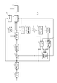
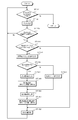
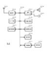
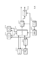
- FIG. 3 shows the configuration of the image encoding device.
- the image encoding device 10 includes an analog / digital conversion unit (A / D conversion unit) 11, a screen rearrangement buffer 12, a subtraction unit 13, an orthogonal transformation unit 14, a quantization unit 15, a lossless encoding unit 16, and a storage buffer 17.
- the rate control unit 18 is provided.
- the image encoding device 10 includes an inverse quantization unit 21, an inverse orthogonal transform unit 22, an addition unit 23, a deblocking filter 24, a frame memory 26, an intra prediction unit 31, a motion prediction / compensation unit 32, a predicted image / optimum A mode selection unit 33 is provided.
- the A / D converter 11 converts an analog image signal into digital image data and outputs the digital image data to the screen rearrangement buffer 12.
- the screen rearrangement buffer 12 rearranges the frames of the image data output from the A / D conversion unit 11.
- the screen rearrangement buffer 12 rearranges the frames according to the GOP (Group of Pictures) structure related to the encoding process, and converts the rearranged image data into the subtraction unit 13, the rate control unit 18, and the intra prediction unit 31. The result is output to the motion prediction / compensation unit 32.
- GOP Group of Pictures
- the subtraction unit 13 is supplied with the image data output from the screen rearrangement buffer 12 and the predicted image data selected by the predicted image / optimum mode selection unit 33 described later.
- the subtraction unit 13 calculates prediction error data that is a difference between the image data output from the screen rearrangement buffer 12 and the prediction image data supplied from the prediction image / optimum mode selection unit 33, and sends the prediction error data to the orthogonal transformation unit 14. Output.
- the orthogonal transform unit 14 performs orthogonal transform processing such as discrete cosine transform (DCT) and Karoonen-Loeve transform on the prediction error data output from the subtraction unit 13.
- the orthogonal transform unit 14 outputs transform coefficient data obtained by performing the orthogonal transform process to the quantization unit 15.
- the quantization unit 15 is supplied with transform coefficient data output from the orthogonal transform unit 14 and a quantization parameter (quantization scale) from an information generation unit 19 described later.
- the quantization unit 15 quantizes the transform coefficient data and outputs the quantized data to the lossless encoding unit 16 and the inverse quantization unit 21. Further, the quantization unit 15 changes the bit rate of the quantized data according to the quantization parameter set by the rate control unit 18.
- the lossless encoding unit 16 includes quantization data from the quantization unit 15, identification information and difference information from the information generation unit 19 described later, prediction mode information from the intra prediction unit 31, and prediction mode information from the motion prediction / compensation unit 32. A differential motion vector or the like is supplied. Also, information indicating whether the optimal mode is intra prediction or inter prediction is supplied from the predicted image / optimum mode selection unit 33.
- the prediction mode information includes a prediction mode, block size information of a motion prediction unit, and the like according to intra prediction or inter prediction.
- the lossless encoding unit 16 performs lossless encoding processing on the quantized data by, for example, variable length encoding or arithmetic encoding, generates stream information, and outputs the stream information to the accumulation buffer 17. Moreover, the lossless encoding part 16 performs the lossless encoding of the prediction mode information supplied from the intra prediction part 31, when the optimal mode is intra prediction. Further, when the optimal mode is inter prediction, the lossless encoding unit 16 performs lossless encoding of the prediction mode information, the difference motion vector, and the like supplied from the motion prediction / compensation unit 32. Further, the lossless encoding unit 16 performs lossless encoding of information relating to the quantization parameter, such as difference information. The lossless encoding unit 16 includes the information after lossless encoding in the stream information.
- the accumulation buffer 17 accumulates the stream information from the lossless encoding unit 16.
- the accumulation buffer 17 outputs the accumulated stream information at a transmission rate corresponding to the transmission path.
- the rate control unit 18 monitors the free capacity of the accumulation buffer 17, and when the free capacity is small, the bit rate of the quantized data is lowered, and when the free capacity is sufficiently large, the quantized data is stored.
- the quantization parameter is set so that the bit rate is increased.
- the rate control unit 18 detects an activity that is information indicating the complexity of the image, for example, the dispersion of the pixel values, using the image data supplied from the screen rearrangement buffer. Based on the detection result of the complexity of the image, the rate control unit 18 sets the quantization parameter so that, for example, an image portion having a low pixel dispersion value is coarsely quantized and a portion other than that is finely quantized.
- the rate control unit 18 outputs the set quantization parameter to the information generation unit 19.
- the information generation unit 19 outputs the quantization parameter supplied from the rate control unit 18 to the quantization unit 15.
- the information generation unit 19 uses a quantization parameter of an encoded block that is spatially or temporally adjacent to the encoding target block as a selection candidate.
- the information generation unit 19 selects a quantization parameter from the selection candidates according to the quantization parameter set by the rate control unit 18 and sets it as a predicted quantization parameter.
- the information generation unit 19 identifies the identification information corresponding to the selected quantization parameter, that is, the identification information for selecting the predicted quantization parameter from the selection candidates, and the difference between the predicted quantization parameter and the set quantization parameter.
- the difference information indicating is generated.
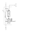
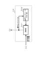
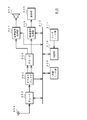
- FIG. 4 shows the configuration of the information generation unit.
- the information generation unit 19 includes a quantization parameter memory unit 191 and a difference calculation unit 192.
- the information generation unit 19 outputs the quantization parameter supplied from the rate control unit 18 to the quantization unit 15. Further, the information generation unit 19 supplies the quantization parameter supplied from the rate control unit 18 to the quantization parameter memory unit 191 and the difference calculation unit 192.
- the quantization parameter memory unit 191 stores the supplied quantization parameter.
- the difference calculation unit 192 calculates a spatially or temporally surrounding block that has been encoded, based on the quantization parameter of the encoded block stored in the quantization parameter memory unit 191.
- a quantization parameter is read as a selection candidate. Further, at least blocks with overlapping quantization parameters, or blocks that are not quantized using quantization parameters, for example, blocks whose transform coefficient data to be quantized by the quantization unit 15 are all “0” are excluded from selection candidates. To do.
- the difference calculation unit 192 selects a block (hereinafter referred to as “skip block”) determined to be skipped based on information from a motion prediction / compensation unit 32 and a predicted image / optimum mode selection unit 33, which will be described later, from the selection candidates. exclude.
- the difference calculation unit 192 selects the quantization parameter from the selection candidates according to the quantization parameter of the encoding target block, that is, the quantization parameter supplied from the rate control unit 18, and sets it as the predicted quantization parameter. Further, the difference calculation unit 192 generates identification information for selecting the prediction quantization parameter from the selection candidates and difference information indicating the difference between the prediction quantization parameter and the quantization parameter of the encoding target block to generate lossless encoding. To the unit 16.
- the inverse quantization unit 21 performs an inverse quantization process on the quantized data supplied from the quantization unit 15.
- the inverse quantization unit 21 outputs transform coefficient data obtained by performing the inverse quantization process to the inverse orthogonal transform unit 22.
- the inverse orthogonal transform unit 22 performs an inverse orthogonal transform process on the transform coefficient data supplied from the inverse quantization unit 21, and outputs the obtained data to the addition unit 23.
- the adding unit 23 adds the data supplied from the inverse orthogonal transform unit 22 and the predicted image data supplied from the predicted image / optimum mode selection unit 33 to generate decoded image data, and the deblocking filter 24 and intra prediction are added. To the unit 31.
- the decoded image data is used as image data for the reference image.
- the deblocking filter 24 performs a filter process for reducing block distortion that occurs during image coding.
- the deblocking filter 24 performs a filter process for removing block distortion from the decoded image data supplied from the adding unit 23, and outputs the decoded image data after the filter process to the frame memory 26.
- the frame memory 26 holds the decoded image data after the filtering process supplied from the deblocking filter 24.
- the decoded image data held in the frame memory 26 is supplied to the motion prediction / compensation unit 32 as reference image data.
- the intra prediction unit 31 performs prediction in all candidate intra prediction modes using the input image data of the encoding target image supplied from the screen rearrangement buffer 12 and the reference image data supplied from the addition unit 23. And determine the optimal intra prediction mode. For example, the intra prediction unit 31 calculates the cost function value in each intra prediction mode, and sets the intra prediction mode in which the coding efficiency is the best based on the calculated cost function value as the optimal intra prediction mode. The intra prediction unit 31 outputs the predicted image data generated in the optimal intra prediction mode and the cost function value in the optimal intra prediction mode to the predicted image / optimum mode selection unit 33. Further, the intra prediction unit 31 outputs prediction mode information indicating the optimal intra prediction mode to the lossless encoding unit 16.
- the motion prediction / compensation unit 32 performs prediction in all candidate inter prediction modes using the input image data of the encoding target image supplied from the screen rearrangement buffer 12 and the reference image data supplied from the frame memory 26. To determine the optimal inter prediction mode. For example, the motion prediction / compensation unit 32 calculates the cost function value in each inter prediction mode, and sets the inter prediction mode in which the coding efficiency is the best based on the calculated cost function value as the optimal inter prediction mode. The motion prediction / compensation unit 32 outputs the predicted image data generated in the optimal inter prediction mode and the cost function value in the optimal inter prediction mode to the predicted image / optimum mode selection unit 33. Further, the motion prediction / compensation unit 32 outputs prediction mode information related to the optimal inter prediction mode to the lossless encoding unit 16 and the information generation unit 19.
- the predicted image / optimum mode selection unit 33 compares the cost function value supplied from the intra prediction unit 31 with the cost function value supplied from the motion prediction / compensation unit 32, and encodes the one having the smaller cost function value. Select the optimal mode with the best efficiency. Further, the predicted image / optimum mode selection unit 33 outputs the predicted image data generated in the optimal mode to the subtraction unit 13 and the addition unit 23. Further, the predicted image / optimum mode selection unit 33 outputs information indicating whether the optimal mode is the intra prediction mode or the inter prediction mode to the lossless encoding unit 16 and the information generation unit 19. Note that the predicted image / optimum mode selection unit 33 switches between intra prediction and inter prediction in units of slices.
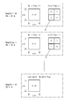
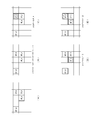
- FIG. 5 illustrates the hierarchical structure of the coding unit.
- a prediction unit PU: Prediction Unit
- TU Transform Unit
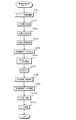
- step ST11 the A / D converter 11 performs A / D conversion on the input image signal.
- step ST12 the screen rearrangement buffer 12 performs image rearrangement.
- the screen rearrangement buffer 12 stores the image data supplied from the A / D conversion unit 11, and rearranges from the display order of each picture to the encoding order.
- step ST13 the subtraction unit 13 generates prediction error data.
- the subtraction unit 13 calculates a difference between the image data of the images rearranged in step ST12 and the predicted image data selected by the predicted image / optimum mode selection unit 33, and generates prediction error data.
- the prediction error data has a smaller data amount than the original image data. Therefore, the data amount can be compressed as compared with the case where the image is encoded as it is.
- the orthogonal transform unit 14 performs an orthogonal transform process.
- the orthogonal transformation unit 14 performs orthogonal transformation on the prediction error data supplied from the subtraction unit 13. Specifically, orthogonal transformation such as discrete cosine transformation and Karhunen-Loeve transformation is performed on the prediction error data, and transformation coefficient data is output.
- step ST15 the quantization unit 15 performs a quantization process.
- the quantization unit 15 quantizes the transform coefficient data.
- rate control is performed as described in the process of step ST25 described later.
- step ST16 the inverse quantization unit 21 performs an inverse quantization process.
- the inverse quantization unit 21 inversely quantizes the transform coefficient data quantized by the quantization unit 15 with characteristics corresponding to the characteristics of the quantization unit 15.
- the inverse orthogonal transform unit 22 performs an inverse orthogonal transform process.
- the inverse orthogonal transform unit 22 performs inverse orthogonal transform on the transform coefficient data inversely quantized by the inverse quantization unit 21 with characteristics corresponding to the characteristics of the orthogonal transform unit 14.
- step ST18 the adding unit 23 generates reference image data.
- the adder 23 adds the predicted image data supplied from the predicted image / optimum mode selection unit 33 and the data after inverse orthogonal transformation of the position corresponding to the predicted image to generate decoded data (reference image data). To do.
- step ST19 the deblocking filter 24 performs filter processing.
- the deblocking filter 24 filters the decoded image data output from the adding unit 23 to remove block distortion.
- step ST20 the frame memory 26 stores reference image data.
- the frame memory 26 stores the decoded data (reference image data) after the filter processing.
- the intra prediction unit 31 and the motion prediction / compensation unit 32 each perform a prediction process. That is, the intra prediction unit 31 performs intra prediction processing in the intra prediction mode, and the motion prediction / compensation unit 32 performs motion prediction / compensation processing in the inter prediction mode.
- the prediction process will be described later with reference to FIG. 7.
- prediction processes in all candidate prediction modes are performed, and cost function values in all candidate prediction modes are calculated.
- the optimal intra prediction mode and the optimal inter prediction mode are selected, and the prediction image generated in the selected prediction mode and its cost function and prediction mode information are predicted image / optimum mode. It is supplied to the selector 33.
- the predicted image / optimum mode selection unit 33 selects predicted image data.
- the predicted image / optimum mode selection unit 33 determines the optimal mode with the best coding efficiency based on the cost function values output from the intra prediction unit 31 and the motion prediction / compensation unit 32. That is, in the predicted image / optimum mode selection unit 33, for example, the coding unit having the best coding efficiency from each layer shown in FIG. 5, the block size of the prediction unit in the coding unit, and intra prediction or inter prediction are selected. Decide what to do. Further, the predicted image / optimum mode selection unit 33 outputs the predicted image data of the determined optimal mode to the subtraction unit 13 and the addition unit 23. As described above, the predicted image data is used for the calculations in steps ST13 and ST18.
- the lossless encoding unit 16 performs a lossless encoding process.
- the lossless encoding unit 16 performs lossless encoding on the quantized data output from the quantization unit 15. That is, lossless encoding such as variable length encoding or arithmetic encoding is performed on the quantized data, and the data is compressed. Further, the lossless encoding unit 16 performs lossless encoding such as prediction mode information corresponding to the prediction image data selected in step ST22, and adds prediction mode information to stream information generated by lossless encoding of the quantized data. Lossless encoded data is included.
- step ST24 the accumulation buffer 17 performs accumulation processing.
- the accumulation buffer 17 accumulates the stream information output from the lossless encoding unit 16.
- the stream information stored in the storage buffer 17 is read as appropriate and transmitted to the decoding side via the transmission path.
- step ST25 the rate control unit 18 performs rate control.
- the rate control unit 18 controls the quantization operation rate of the quantization unit 15 so that overflow or underflow does not occur in the storage buffer 17.
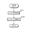
- the intra prediction unit 31 performs an intra prediction process.
- the intra prediction unit 31 performs intra prediction on the image of the prediction unit to be encoded in all candidate intra prediction modes. Note that the decoded image data before the blocking filter processing is performed by the deblocking filter 24 is used as the image data of the decoded image referred to in the intra prediction.
- intra prediction is performed in all candidate intra prediction modes, and cost function values are calculated for all candidate intra prediction modes. Then, based on the calculated cost function value, one intra prediction mode with the best coding efficiency is selected from all the intra prediction modes.
- step ST32 the motion prediction / compensation unit 32 performs an inter prediction process.
- the motion prediction / compensation unit 32 uses the decoded image data after the deblocking filter processing stored in the frame memory 26 to perform inter prediction processing in a candidate inter prediction mode.
- inter prediction processing prediction processing is performed in all candidate inter prediction modes, and cost function values are calculated for all candidate inter prediction modes. Then, based on the calculated cost function value, one inter prediction mode with the best coding efficiency is selected from all the inter prediction modes.
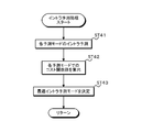
- step ST41 the intra prediction unit 31 performs intra prediction in each prediction mode.
- the intra prediction unit 31 generates predicted image data for each intra prediction mode using the decoded image data before the blocking filter processing.
- the intra prediction unit 31 calculates a cost function value in each prediction mode.
- the calculation of the cost function value is, for example, H.264.
- JM Joint Model
- Cost (Mode ⁇ ) D + ⁇ ⁇ R (1)
- ⁇ indicates the entire set of prediction modes that are candidates for encoding the image of the prediction unit.
- D indicates the differential energy (distortion) between the predicted image and the input image when encoding is performed in the prediction mode.
- R is a generated code amount including orthogonal transform coefficients and prediction mode information, and ⁇ is a Lagrange multiplier given as a function of a quantization parameter.
- Cost (Mode ⁇ ) D + QP2Quant (QP) ⁇ Header_Bit (2)
- ⁇ indicates the entire set of prediction modes that are candidates for encoding the image of the prediction unit.
- D indicates the differential energy (distortion) between the predicted image and the input image when encoding is performed in the prediction mode.
- Header_Bit is a header bit for the prediction mode
- QP2Quant is a function given as a function of a quantization parameter. That is, in the Low-complexity mode, as a process of step ST42, the above-described formula (2) is used for all prediction modes that are candidates, using prediction image generation and header bits such as motion vectors and prediction mode information. Is calculated for each prediction mode.
- step ST43 the intra prediction unit 31 determines the optimal intra prediction mode. Based on the cost function value calculated in step ST42, the intra prediction unit 31 selects one intra prediction mode having a minimum cost function value from them, and determines the optimal intra prediction mode.
- step ST51 the motion prediction / compensation unit 32 performs a motion detection process.
- the motion prediction / compensation unit 32 detects the motion vector and proceeds to step ST52.
- step ST52 the motion prediction / compensation unit 32 performs a motion compensation process.
- the motion prediction / compensation unit 32 performs motion compensation using the reference image data based on the motion vector detected in step ST51, and generates predicted image data.
- step ST53 the motion prediction / compensation unit 32 calculates a cost function value.
- the motion prediction / compensation unit 32 calculates the cost function value as described above using the input image data of the prediction unit to be encoded, the predicted image data generated in step ST52, and the process proceeds to step ST54.
- step ST54 the motion prediction / compensation unit 32 determines the optimal inter prediction mode.
- the motion prediction / compensation unit 32 performs the processing from step ST51 to step ST53 for every inter prediction mode.
- the motion prediction / compensation unit 32 determines the reference index that minimizes the cost function value calculated for each prediction mode, the block size of the coding unit, and the block size of the prediction unit in the coding unit, thereby determining the optimal inter prediction mode. To decide. Note that, in determining the mode that minimizes the cost function, the cost function value when the inter prediction is performed in the skip mode is also used.
- the motion prediction / compensation unit 32 sends the prediction image data in the optimum inter prediction mode to the subtraction unit 13 and the addition unit 23. Prediction image data is generated so that it can be supplied.
- the image encoding device 10 sets the quantization parameter so as to perform adaptive quantization according to the complexity of the image for each block. Further, the image encoding device 10 generates identification information and difference information, performs lossless encoding, and includes them in the stream information in order to improve the encoding efficiency of the quantization parameter used in the quantization process of step ST15.
- the rate control unit 18 sets a quantization parameter using a code amount control method defined by TM5 of MPEG2, for example.
- step 1 the allocated code amount for each picture in the GOP (Group Of Pictures) is distributed to the unencoded picture including the allocation target picture based on the allocated bit amount R. This distribution is repeated in the order of the coded pictures in the GOP. At that time, code amount allocation to each picture is performed using the following two assumptions.
- the first assumption is that the product of the average quantization scale code and the generated code amount used when encoding each picture is constant for each picture type unless the screen changes.
- S I , S P , and S B are generated encoded bits at the time of picture encoding
- Q I , Q P , and Q B are average quantization scale codes at the time of picture encoding.
- the initial value is a value represented by the following equations (6), (7), (8) using bit_rate [bits / sec] which is the target code amount.
- X I 160 ⁇ bit_rate / 115 (6)
- X P 160 ⁇ bit_rate / 115 (7)
- X B 160 ⁇ bit_rate / 115 (8)
- the quantization scale code for the B picture is always 1.4 times the quantization scale code for the I and P pictures. This is because the image quality of the I and P pictures is improved by adding a code amount that can be saved in the B picture to the I and P pictures by quantizing the B picture slightly coarser than the I and P pictures. At the same time, it is assumed that the image quality of the B picture referring to this is also improved.
- the allocated code amount (T I , T P , T B ) for each picture in the GOP is a value represented by equations (10), (11), (12).
- picture_rate indicates the number of pictures displayed per second in the sequence.
- N P, N B is not yet encoded in GOP, P, is the number of B-pictures. That is, among the uncoded pictures in the GOP, for a picture type that is different from the picture to be assigned, the amount of code generated by the picture under the above-described image quality optimization condition is the occurrence of the picture to be assigned. Estimate how many times the code amount is. Next, it is determined how many code amounts of the allocation target picture the estimated generated code amount generated in the entire uncoded picture corresponds to. For example, the denominator second term of the first argument, N p X p / X I K P , of the formula relating to T I is the number of N P uncoded pictures in the GOP converted into I pictures Indicates whether to convert to. Further, the N P, the generated code amount for P-picture, by multiplying the ratio S P / S I for generated code amount of an I picture, X I as described above, X P, obtained by expressing in K P.
- the bit amount for the allocation target picture is obtained by dividing the allocation code amount R for the uncoded picture by this number.
- a lower limit is set for the value in consideration of a fixedly required code amount for the header or the like.
- R is updated by the following equation (14).
- N is the number of pictures in the GOP.
- the initial value of R at the beginning of the sequence is 0.
- step 2 a quantization scale code is obtained in order to match the allocated code amount (T I , T P , T B ) obtained in step 1 with the actual code amount.
- the quantization scale code is obtained by feedback control in units of macroblocks based on the capacity of three types of virtual buffers set independently for each picture type.
- the occupancy amount of the virtual buffer is obtained by equations (15) to (17).
- d 0 I , d 0 P , d 0 B are initial occupancy of each virtual buffer
- B j is the amount of generated bits from the beginning of the picture to the j-th macro block
- MB cnt is a macro block in one picture Is a number.
- the virtual buffer occupancy at the end of each picture encoding (dMB cnt I , dMB cnt p , dMB cnt B ) is the same picture type, and the initial virtual buffer occupancy for the next picture (d 0 I , d 0 P , d 0 B ).
- r is a parameter that controls the response speed of the feedback loop, called a reaction parameter, and is given by equation (19).
- step 3 uses the luminance signal pixel values of the original image, and for example, the pixel values of a total of eight blocks of four 8 ⁇ 8 blocks in the frame DCT mode and four 8 ⁇ 8 blocks in the field DCT coding mode are used. And given by equations (21)-(23).
- Var_sblk shown in Expression (21) is the square sum of the difference between the pixel data of each pixel and its average value, and the value increases as the image of the 8 ⁇ 8 block becomes more complex.
- P k in the equations (22) and (23) is the pixel value in the luminance signal block of the original image. The reason why the minimum value (min) is taken in the equation (22) is to make quantization fine when only a part of a 16 ⁇ 16 macroblock has a flat part. Further, a normalized activity N actj whose value is in the range of 0.5 to 2 is obtained from the equation (24).
- avg_act is an average value of activities in the picture encoded immediately before.
- the quantization scale code mquant j considering the visual characteristics is given by the equation (25) based on the reference quantization scale code Q j .
- the rate control unit 18 outputs the quantization scale code mquant j calculated as described above as a quantization parameter. Also, with respect to the macroblock located at the slice boundary, the quantization parameter is generated in the same manner as the macroblock located outside the slice boundary by the above-described method.
- the quantization parameter is not limited to the case where it is determined based on the activity as described above, but may be determined so that the cost function value becomes small.
- the information generation unit 19 selects a coded quantization parameter that is spatially or temporally adjacent to the coding target block as a selection candidate. Further, the information generation unit 19 selects a quantization parameter from the selection candidates according to the quantization parameter set for the encoding target block, and sets it as the predicted quantization parameter. Furthermore, the information generation unit 19 generates difference information indicating the difference between the identification information for selecting the prediction quantization parameter from the selection candidates, and the prediction quantization parameter and the quantization parameter set in the encoding target block. .
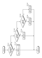
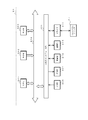
- FIG. 10 is a diagram for explaining the operation of the information generation unit, and shows an encoding target frame and an encoded frame having the closest time in the display order.
- the quantization parameter of the encoding target block in the encoding target frame is “QP_O”.
- the quantization parameter of the encoded block adjacent to the left is “QP_A”, for example.
- the quantization parameters of the encoded blocks adjacent to the upper, upper right, upper left, and lower left are, for example, “QP_B”, “QP_C”, “QP_D”, and “QP_E”.
- the quantization parameter of the encoded block that is temporally adjacent is set to “QP_T”.
- the quantization parameters “QP_A” to “QP_E” and “QP_T” are stored in the quantization parameter memory unit 191.
- Each block is a minimum unit block whose quantization parameter can be changed.
- the difference calculation unit 192 selects a quantization parameter having the smallest difference from the quantization parameter set in the encoding target block, using the quantization parameter of the encoded block adjacent to the encoding target block as a selection candidate. Is selected as the prediction quantization parameter.
- the difference calculation unit 192 generates identification information for selecting the prediction quantization parameter from the selection candidates, and difference information indicating a difference between the prediction quantization parameter and the quantization parameter of the encoding target block.
- FIG. 11 is a diagram illustrating an operation example of the information generation unit. A case where no quantization parameter is set for a block because there is no skip block or residual information is indicated by “ ⁇ ”.
- the information generation unit 19 sets identification information such as an index number in advance for the selection candidate.
- the identification information may be set for an adjacent encoded block, or may be set for a quantization parameter of an adjacent encoded block.
- the information generation unit 19 sets index numbers in advance in the order of the adjacent encoded blocks as a predetermined order.
- the predetermined arrangement order is, for example, an arrangement order giving priority to any one of the encoded block adjacent to the left side, the encoded block adjacent to the upper side, and the encoded block adjacent in time.
- the information generation unit 19 may be able to switch the arrangement order. When the arrangement order can be switched, information indicating the arrangement order is included in the stream information.
- the lossless encoding unit 16 and the information generation unit 19 perform setting of the identification information and lossless encoding so that the code amount when the identification information of the prioritized block is encoded is reduced.
- the difference calculation unit 192 selects the candidate having the smallest difference from the quantization parameter of the encoding target block from the selection candidates, and uses the identification information set for the selected candidate, so that the selection candidate Identification information for selecting a predictive quantization parameter is generated. Further, the difference calculation unit 192 generates difference information indicating a difference between the prediction quantization parameter that is the quantization parameter of the selected candidate and the quantization parameter of the encoding target block. For example, when the encoded block adjacent on the left side in FIG. 11 is prioritized, the information generation unit 19 sets “0 (index number): QP_A block” “1: QP_B block” “2: QP_D block” "3: QP_T block".
- the encoding target block that approximates the image of the left block The amount of data is reduced for images with many images.
- the encoding target block that approximates the image of the upper block
- the amount of data is reduced for images with many images.
- the temporally adjacent blocks are prioritized and the quantization parameters “QP_T”, “QP_A”, “QP_B”, “QP_C”, “QP_D”, and “QP_E” are in block order, they approximate the temporally adjacent block images. The amount of data is reduced for an image with many encoding target blocks, that is, an image with many stationary subjects.
- the information generation unit 19 sets an index number with the adjacent encoded block as a predetermined arrangement order. For example, the information generation unit 19 sets the index number in order from the quantization parameter with the smallest parameter value. That is, in the case of FIG. 11, the information generation unit 19 sets the index number as “0 (index number): 32 (quantization parameter)” “1:40” “2:35” “3:31”. .
- the difference calculation unit 192 When there is no selection candidate, the difference calculation unit 192 generates difference information indicating a difference between the quantization parameter SliceQPY of the initial value in the slice and the set quantization parameter.
- FIG. 12 is a flowchart showing processing for quantization parameters in encoding.
- the image encoding device 10 generates information for obtaining a quantization parameter unit minimum size (MinQpUnitSize).
- the minimum quantization parameter unit size is the minimum size at which the quantization parameter can be adaptively switched.
- the image encoding apparatus 10 uses, for example, a difference with the minimum transform unit size (MinTransformUnitSize) as information for obtaining the minimum quantization parameter unit size (MinQpUnitSize).
- MinQpUnitSize The minimum quantization parameter unit size (MinQpUnitSize) is determined by equation (26).
- MinQpUnitSize 1 ⁇ (log2_min_transform_unit_size_minus2 + Log2_min_qp_unit_size_offset + 2) (26) Note that “log2_min_transform_unit_size_minus2” in Equation (26) is a parameter that determines the minimum transform unit size (MinTransformUnitSize).
- MinTransformUnitSize 1 ⁇ (log2_min_transform_unit_size_minus2 +2) ... (27)
- MinQpUnitSize minimum quantization parameter unit size
- MinTransformUnitSize minimum transform unit size
- the minimum quantization parameter unit size may be determined according to the coding unit size.
- the image encoding device 10 specifies, for example, information (log2_min_coding_block_size_minus3) for specifying the minimum size of the coding unit CU and the maximum size of the coding unit CU as information for obtaining the minimum quantization parameter unit size (MinQpUnitSize).
- Information log2_diff_max_min_coding_block_size
- log2MinQpUnitSize log2_min_coding_block_size_minus 3 + 3 + log2_diff_max_min_coding_block_size -log2_min_qp_unit_size_offset
- the minimum quantization parameter unit size is reduced. For example, when the minimum size of the coding unit CU is “8 ⁇ 8” and the maximum size is “64 ⁇ 64”, if “log2_min_qp_unit_size_offset” is set to “1”, the minimum size of the quantization parameter unit is “32 ⁇ 32”. . If “log2_min_qp_unit_size_offset” is set to “2”, the minimum quantization parameter unit size is “16 ⁇ 16”.
- the image encoding device 10 performs processing for including the generated information in the stream information.
- the image encoding device 10 includes “log2_min_qp_unit_size_offset” and “log2_min_qp_unit_size_offset”, which is a parameter for determining the minimum transform unit size (MinTransformUnitSize), in the stream information, and proceeds to step ST63. Also, when determining the minimum quantization parameter unit size according to the coding unit size, “log2_min_coding_block_size_minus3”, “log2_diff_max_min_coding_block_size”, and “log2_min_qp_unit_size_offset” are included in the stream information.
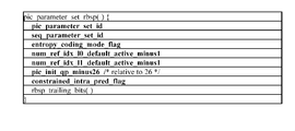
- the image encoding device 10 includes the generated information in a sequence parameter set (SPS) defined as, for example, the syntax of RBSP (raw byte sequence payload). Note that FIG. 13 illustrates a sequence parameter set.
- SPS sequence parameter set
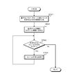
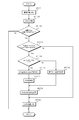
- step ST63 the image encoding device 10 determines whether there is a frame to be encoded. If there is a frame to be encoded, the image encoding apparatus 10 proceeds to step ST64, performs the frame encoding process shown in FIG. 14, and ends the encoding process if it does not exist.
- step ST71 the image encoding device 10 determines whether there is a slice to be encoded. If there is a slice to be encoded, the image encoding device 10 proceeds to step ST72, and if not, ends the encoding process of the frame.
- step ST72 the image encoding device 10 determines the quantization parameter of the slice to be encoded.
- the image encoding device 10 determines the quantization parameter of the initial value in the slice so that the target code amount is obtained, and proceeds to step ST73.
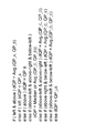
- step ST ⁇ b> 73 the image encoding device 10 calculates “slice_qp_delta”.
- the initial quantization parameter SliceQPY in the slice has the relationship shown in Expression (30), and “pic_init_qp_minus26” is set in advance by the user or the like. Therefore, the image coding apparatus 10 calculates “slice_qp_delta” to be the quantization parameter determined in step ST72, and proceeds to step ST74.
- SliceQPY 26 + pic_init_qp_minus26 + slice_qp_delta (30)
- the image encoding device 10 includes “slice_qp_delta” and “pic_init_qp_minus26” in the stream information.
- the image encoding device 10 includes the calculated “slice_qp_delta” in, for example, the slice header of the stream information.
- the image encoding device 10 includes the set “pic_init_qp_minus26” in, for example, the picture parameter set of the stream information.
- the image decoding apparatus that decodes the stream information performs the operation of Expression (30), thereby performing the quantization parameter SliceQPY of the initial value in the slice. Can be calculated.
- 15 illustrates a sequence parameter set
- FIG. 16 illustrates a slice header.
- step ST75 the image encoding device 10 performs a slice encoding process.
- FIG. 17 is a flowchart showing slice encoding processing.
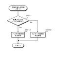
- step ST81 of FIG. 17 the image encoding device 10 determines whether there is a coding unit CU to be encoded. If there is a coding unit that has not been subjected to the encoding process in the slice to be encoded, the image encoding device 10 proceeds to step ST82. Moreover, the image coding apparatus 10 complete
- step ST82 the image encoding device 10 determines whether there is a transform unit TU in the coding unit CU to be encoded. If there is a transform unit, the image coding apparatus 10 proceeds to step ST83, and if there is no transform unit, the image coding apparatus 10 proceeds to step ST87. For example, when all the coefficients to be quantized using the quantization parameter are “0” or skip blocks, the process proceeds to step ST87.
- step ST83 the image encoding device 10 determines the quantization parameter of the coding unit CU to be encoded.
- the rate control unit 18 of the image encoding device 10 determines the quantization parameter according to the complexity of the image of the coding unit as described above or the cost function value becomes small, and proceeds to step ST84.
- the image encoding device 10 sets identification information as a selection candidate.
- the information generation unit 19 of the image encoding device 10 uses a coding quantization parameter surrounding the coding unit to be encoded spatially or temporally as a selection candidate. Further, the information generation unit 19 excludes these from the selection candidates when there is no skip block or residual information, and when the quantization parameter is not set for the block, and when the quantization parameter is equal to other candidates. .
- the image encoding device 10 sets identification information, for example, an index (ref_qp_block_index) for the selection candidate, and proceeds to step ST85.
- the image encoding device 10 generates identification information and difference information.
- the information generation unit 19 of the image encoding device 10 selects a candidate having the smallest difference from the quantization parameter of the coding unit to be encoded from the selection candidates and sets it as a predicted quantization parameter.
- the information generation unit 19 generates identification information by using the selected candidate index (ref_qp_block_index) as identification information for selecting a prediction quantization parameter from the selection candidates.
- the information generation unit 19 sets the difference (qb_qp_delta) between the prediction quantization parameter and the quantization parameter of the coding unit to be encoded as difference information, and proceeds to step ST86.
- step ST86 the image encoding device 10 includes the identification information and the difference information in the stream information.
- the lossless encoding unit 16 of the image encoding device 10 losslessly encodes the identification information and the difference information generated by the information generation unit 19 and includes them in the stream information, and the process proceeds to step ST87.
- step ST87 the image encoding device 10 performs quantization on the coding unit using the determined quantization parameter in the quantization unit 15, and returns to step ST81.
- the image encoding device 10 has the largest difference between the quantization parameter of the encoded block spatially or temporally adjacent to the encoding target block and the quantization parameter of the encoding target block.
- the candidate that becomes smaller is selected as the predictive quantization parameter.
- the image encoding device 10 generates identification information corresponding to the selected quantization parameter.
- the image encoding device 10 generates difference information indicating a difference between the prediction quantization parameter and the quantization parameter of the encoding target block.
- the image encoding device 10 includes the generated identification information and difference identification in the stream information.
- the image encoding device 10 can improve the encoding efficiency of the quantization parameter.
- FIG. 18 shows a configuration of an image decoding apparatus that performs decoding processing of stream information.
- the image decoding device 50 includes a storage buffer 51, a lossless decoding unit 52, an inverse quantization unit 53, an inverse orthogonal transform unit 54, an addition unit 55, a deblocking filter 56, a screen rearrangement buffer 57, a digital / analog conversion unit (D / A conversion unit) 58. Furthermore, the image decoding device 50 includes a quantization parameter calculation unit 59, a frame memory 61, an intra prediction unit 71, a motion compensation unit 72, and a selector 73.
- the accumulation buffer 51 accumulates the transmitted stream information.
- the lossless decoding unit 52 decodes the stream information supplied from the accumulation buffer 51 by a method corresponding to the encoding method of the lossless encoding unit 16 of FIG.
- the lossless decoding unit 52 operates as an information acquisition unit and acquires various information from the stream information. For example, the lossless decoding unit 52 outputs prediction mode information obtained by decoding the stream information to the intra prediction unit 71 and the motion compensation unit 72. In addition, the lossless decoding unit 52 outputs the difference motion vector, the threshold value, or threshold value generation information obtained by decoding the stream information to the motion compensation unit 72. Further, the lossless decoding unit 52 outputs information on the quantization parameter obtained by decoding the stream information, such as difference information, to the quantization parameter calculation unit 59. Further, the lossless decoding unit 52 outputs the quantized data obtained by decoding the stream information to the inverse quantization unit 53.
- the inverse quantization unit 53 uses the quantization parameter supplied from the quantization parameter calculation unit 59 and uses the quantization parameter supplied from the lossless decoding unit 52 in a method corresponding to the quantization method of the quantization unit 15 in FIG. Inverse quantization of digitized data.
- the inverse orthogonal transform unit 54 performs inverse orthogonal transform on the output of the inverse quantization unit 53 by a method corresponding to the orthogonal transform method of the orthogonal transform unit 14 in FIG.
- the addition unit 55 adds the data after inverse orthogonal transformation and the predicted image data supplied from the selector 73 to generate decoded image data, and outputs the decoded image data to the deblocking filter 56 and the intra prediction unit 71.
- the deblocking filter 56 performs deblocking filter processing on the decoded image data supplied from the addition unit 55, removes block distortion, supplies the frame memory 61 to the frame memory 61, and outputs the frame memory 61 to the screen rearrangement buffer 57. To do.
- the screen rearrangement buffer 57 rearranges images. That is, the order of frames rearranged for the encoding order by the screen rearrangement buffer 12 in FIG. 3 is rearranged in the original display order and output to the D / A converter 58.
- the D / A conversion unit 58 performs D / A conversion on the image data supplied from the screen rearrangement buffer 57 and outputs it to a display (not shown) to display an image.
- the quantization parameter calculation unit 59 restores the quantization parameter based on the information supplied from the lossless decoding unit 52 and outputs it to the inverse quantization unit 53.
- FIG. 19 shows a configuration of a quantization parameter calculation unit.
- the quantization parameter calculation unit 59 includes a calculation unit 591 and a quantization parameter memory unit 592.
- the calculation unit 591 is used in the quantization in the encoding performed in the decoding target block using the information supplied from the lossless decoding unit 52 and the quantization parameter stored in the quantization parameter memory unit 592.
- the quantization parameter is restored and output to the inverse quantization unit 53.
- the calculation unit 591 stores the quantization parameter of the decoding target block in the quantization parameter memory unit 592.
- the calculation unit 591 performs the calculation of Expression (30) using, for example, “pic_init_qp_minus26” extracted from the picture parameter set and “slice_qp_delta” extracted from the slice header, calculates the quantization parameter SliceQPY, and calculates the inverse quantization unit To 53.
- the arithmetic unit 591 uses the identification information and difference information supplied from the lossless decoding unit 52 and the quantization parameter of the decoded block stored in the quantization parameter memory unit 592 to quantize the quantization target block. Calculation parameters are calculated.
- the calculation unit 591 outputs the calculated quantization parameter to the inverse quantization unit 53.
- the calculation unit 591 uses the quantization parameter of the decoded block stored in the quantization parameter memory unit 592 to quantize the block of the decoded block spatially or temporally with respect to the decoding target block. Read the parameter.
- the calculation unit 591 sets selection candidates in the same manner as the difference calculation unit 192.
- the calculation unit 591 excludes at least blocks with overlapping quantization parameters or blocks that are not subjected to inverse quantization using the quantization parameters as selection candidates. Furthermore, the calculation unit 591 sets identification information, for example, an index (ref_qp_block_index) equal to the difference calculation unit 192, for each candidate quantization parameter. That is, the arithmetic unit 591 sets an index (ref_qp_block_index) with adjacent decoded blocks as a predetermined arrangement order.
- identification information for example, an index (ref_qp_block_index) equal to the difference calculation unit 192, for each candidate quantization parameter. That is, the arithmetic unit 591 sets an index (ref_qp_block_index) with adjacent decoded blocks as a predetermined arrangement order.
- the calculation unit 591 is a quantization parameter “ref_qp (ref_qp_block_index)” corresponding to the identification information supplied from the lossless decoding unit 52, that is, the prediction quantization parameter, and the difference indicated by the difference information supplied from the lossless decoding unit 52.
- the calculation of Expression (31) is performed using (qb_qp_delta).
- the calculation unit 91 outputs the calculated quantization parameter (CurrentQP) to the inverse quantization unit 53 as a quantization parameter to be decoded. If there is no selection candidate, the calculation unit 591 outputs the quantization parameter of the initial value in the slice to the inverse quantization unit 53.
- the calculation unit 591 sets an index (ref_qp_block_index) with the decoded blocks as the specified arrangement order. In this way, even when the arrangement order is changed in the image encoding device 10, the image decoding device 50 can restore the quantization parameter used in the image encoding device 10.
- the frame memory 61 stores the decoded image data after the filtering process is performed by the deblocking filter 24 as reference image data.
- the intra prediction unit 71 generates predicted image data based on the prediction mode information supplied from the lossless decoding unit 52 and the decoded image data supplied from the addition unit 55, and outputs the generated predicted image data to the selector 73. .
- the motion compensation unit 72 reads the reference image data from the frame memory 61 based on the prediction mode information and the difference motion vector supplied from the lossless decoding unit 52, performs motion compensation, and generates predicted image data.
- the motion compensation unit 72 outputs the generated predicted image data to the selector 73. Also, the motion compensation unit 72 generates predicted image data by switching filter characteristics according to the magnitude of the motion vector.
- the selector 73 selects the intra prediction unit 71 for intra prediction and the motion compensation unit 72 for inter prediction based on the prediction mode information supplied from the lossless decoding unit 52.
- the selector 73 outputs the predicted image data generated by the selected intra prediction unit 71 or motion compensation unit 72 to the addition unit 55.
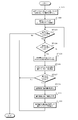
- step ST91 the accumulation buffer 51 accumulates the supplied stream information.
- step ST92 the lossless decoding unit 52 performs lossless decoding processing.
- the lossless decoding unit 52 decodes the stream information supplied from the accumulation buffer 51. That is, quantized data of each picture encoded by the lossless encoding unit 16 in FIG. 3 is obtained.
- the lossless decoding unit 52 performs lossless decoding such as prediction mode information included in the stream information, and outputs the prediction mode information to the intra prediction unit 71 when the obtained prediction mode information is information related to the intra prediction mode. To do.
- the lossless decoding part 52 outputs prediction mode information to the motion compensation part 72, when prediction mode information is the information regarding inter prediction mode.
- the lossless decoding unit 52 outputs the difference motion vector, the threshold value, or threshold value generation information obtained by decoding the stream information to the motion compensation unit 72.
- step ST93 the inverse quantization unit 53 performs an inverse quantization process.
- the inverse quantization unit 53 inversely quantizes the quantized data decoded by the lossless decoding unit 52 with characteristics corresponding to the characteristics of the quantization unit 15 in FIG.
- the inverse orthogonal transform unit 54 performs an inverse orthogonal transform process.
- the inverse orthogonal transform unit 54 performs inverse orthogonal transform on the transform coefficient data inversely quantized by the inverse quantization unit 53 with characteristics corresponding to the characteristics of the orthogonal transform unit 14 of FIG.
- step ST95 the addition unit 55 generates decoded image data.
- the adder 55 adds the data obtained by performing the inverse orthogonal transform process and the predicted image data selected in step ST99 described later to generate decoded image data. As a result, the original image is decoded.
- step ST96 the deblocking filter 56 performs filter processing.
- the deblocking filter 56 performs a deblocking filter process on the decoded image data output from the adding unit 55 to remove block distortion included in the decoded image.
- step ST97 the frame memory 61 performs a storage process of the decoded image data. Note that the decoded image data stored in the frame memory 61 and the decoded image data output from the adder 55 are used for generating predicted image data as reference image data.
- step ST98 the intra prediction unit 71 and the motion compensation unit 72 perform a predicted image generation process.
- the intra prediction unit 71 and the motion compensation unit 72 perform a prediction image generation process corresponding to the prediction mode information supplied from the lossless decoding unit 52, respectively.
- the intra prediction unit 71 when prediction mode information for intra prediction is supplied from the lossless decoding unit 52, the intra prediction unit 71 generates predicted image data based on the prediction mode information.
- the motion compensation unit 72 performs motion compensation based on the prediction mode information to generate predicted image data.
- step ST99 the selector 73 selects predicted image data.
- the selector 73 selects the prediction image supplied from the intra prediction unit 71 and the prediction image data supplied from the motion compensation unit 72, supplies the selected prediction image data to the addition unit 55, and as described above.
- step ST95 it is added to the output of the inverse orthogonal transform unit 54.
- step ST100 the screen rearrangement buffer 57 performs image rearrangement. That is, the screen rearrangement buffer 57 rearranges the order of frames rearranged for encoding by the screen rearrangement buffer 12 of the image encoding device 10 of FIG. 3 to the original display order.
- step ST101 the D / A converter 58 D / A converts the image data from the screen rearrangement buffer 57. This image is output to a display (not shown), and the image is displayed.
- step ST111 the lossless decoding unit 52 determines whether or not the decoding target block is intra-encoded.
- the prediction mode information obtained by performing lossless decoding is prediction mode information for intra prediction
- the lossless decoding unit 52 supplies the prediction mode information to the intra prediction unit 71 and proceeds to step ST112.
- the prediction mode information is inter prediction mode information
- the lossless decoding unit 52 supplies the prediction mode information to the motion compensation unit 72 and proceeds to step ST113.
- the intra prediction unit 71 performs intra prediction image generation processing.
- the intra prediction unit 71 performs intra prediction using the decoded image data before the deblocking filter process and the prediction mode information supplied from the addition unit 55, and generates predicted image data.
- step ST113 the motion compensation unit 72 performs inter prediction image generation processing.
- the motion compensation unit 72 reads reference image data from the frame memory 61 based on information such as prediction mode information supplied from the lossless decoding unit 52 and generates predicted image data.
- FIG. 22 is a flowchart showing processing for quantization parameters in decoding.
- the image decoding apparatus 50 extracts information for obtaining the quantization parameter unit minimum size.
- the image decoding apparatus 50 extracts information for obtaining the minimum encoding parameter unit size, for example, “log2_min_qp_unit_size_offset” from the stream information, and proceeds to step ST122.
- the image decoding apparatus 50 calculates the quantization parameter unit minimum size.
- the image decoding apparatus 50 calculates the quantization parameter unit minimum size (MinQpUnitSize) using “log2_min_qp_unit_size_offset” and the parameter “log2_min_transform_unit_size_minus2” that determines the minimum transform unit size (MinTransformUnitSize). Further, the image decoding device 50 may calculate the quantization parameter unit minimum size (MinQpUnitSize) by the calculation of Expression (29).
- step ST123 the image decoding apparatus 50 determines whether there is a frame to be decoded.
- the image decoding apparatus 50 proceeds to step ST124 when there is a frame to be decoded, and ends the process when there is no frame to be decoded.
- step ST124 the image decoding apparatus 50 determines whether there is a slice to be decoded.
- the image decoding apparatus 50 proceeds to step ST125 when there is a slice to be decoded, and returns to step ST123 when there is no slice to be decoded.
- step ST125 the image decoding apparatus 50 extracts information for obtaining an initial quantization parameter in the slice.
- the lossless decoding unit 52 of the image decoding device 50 extracts “pic_init_qp_minus26” from, for example, a picture parameter set (PPS). Further, “slice_qp_delta” is extracted from the slice header, and the process proceeds to step ST126.
- step ST126 the image decoding apparatus 50 calculates an initial quantization parameter in the slice.
- the quantization parameter calculation unit 59 of the image decoding device 50 performs the calculation of Expression (30) using “pic_init_qp_minus26” and “slice_qp_delta”, calculates the quantization parameter SliceQPY, and proceeds to step ST127.
- step ST127 the image decoding apparatus 50 determines whether there is a coding unit CU to be decoded.
- the image decoding apparatus 50 proceeds to step ST128 when there is a coding unit to be decoded, and returns to step ST124 when there is no coding unit.
- the image decoding apparatus 50 sets identification information as a selection candidate.
- the quantization parameter calculation unit 59 of the image decoding device 50 sets identification information as a selection candidate in the same manner as the information generation unit 19 of the image encoding device 10. That is, the quantization parameter calculation unit 59 uses a decoded coding quantization parameter spatially or temporally surrounding a coding unit to be decoded as a candidate. In addition, the quantization parameter calculation unit 59 excludes a skip block or residual information from the candidate when there is no quantization parameter for the block because there is no skip block or residual information, and when the quantization parameter is equal to another candidate.
- the quantization parameter calculation unit 59 sets identification information, for example, an index (ref_qp_block_index) equal to that of the image encoding device 10 for each candidate quantization parameter, and proceeds to step ST129.
- step ST129 the image decoding device 50 acquires identification information and difference information.
- the lossless decoding unit 52 of the image decoding device 50 extracts the identification information and difference information included in the stream information in the image encoding device 10, that is, the index (ref_qp_block_index) and the difference (qb_qp_delta).
- the lossless decoding unit 52 supplies the extracted identification information and difference information to the quantization parameter calculation unit 59, and proceeds to step ST130.
- the image decoding apparatus 50 calculates a quantization parameter using the identification information and the difference information.
- the quantization parameter calculation unit 59 of the image decoding device 50 uses the quantization parameter “ref_qp (ref_qp_block_index)” corresponding to the index (ref_qp_block_index) that is identification information and the difference (qb_qp_delta) that is difference information to obtain the equation (31). ). That is, the quantization parameter of the coding unit to be decoded is calculated by adding the difference to the predicted quantization parameter.
- the quantization parameter calculation unit 59 outputs the calculated quantization parameter (CurrentQP) of the coding unit to be decoded to the inverse quantization unit 53 and returns to step ST124.
- the quantization parameter related to the decoding target block can be restored even if the quantization information of each block is not included in the stream information. That is, even if the coding efficiency of the quantization parameter is improved by using the identification information and the difference information in the image coding device 10, the image decoding device 50 restores the quantization parameter for each block and correctly performs the decoding process. To generate a decoded image.
- the quantization parameter of the encoded block that is spatially or temporally adjacent to the encoding target block is used as a selection candidate.
- the quantization parameter selected from the selection candidates according to the quantization parameter set for the encoding target block is set as the predicted quantization parameter. Furthermore, by including identification information for selecting a prediction quantization parameter from selection candidates and difference information indicating a difference between the prediction quantization parameter and the quantization parameter set for the encoding target block in the stream information. Therefore, improvement of the encoding efficiency of the quantization parameter has been attempted.
- the selection candidate is not limited to the quantization parameter of the encoded block that is adjacent spatially or temporally, and the last updated quantization parameter may be included in the selection candidate.
- the encoding target The quantization parameter of the block near the block can be set as the predicted quantization parameter.
- the quantization parameter is implicitly or explicitly predicted from the quantization parameter of the selection candidate, and difference information indicating a difference between the predicted quantization parameter and the quantization parameter of the encoding target block may be generated. .
- the quantization parameter unit minimum size (MinQpUnitSize) is determined according to the coding unit size, and is implicitly or explicitly determined from the quantization parameter of the selection candidate.
- MinQpUnitSize the quantization parameter unit minimum size
- the image coding apparatus discriminates information “qp_explicit_flag” indicating whether the quantization parameter is implicitly determined or explicitly determined. Is included in the stream information. Further, it may be determined in advance whether the quantization parameter is implicitly determined or explicitly determined by the image encoding device and the image decoding device.
- Implicitly determining the quantization parameter means that the image decoding apparatus is equal to the image encoding apparatus without supplying identification information for selecting the predicted quantization parameter from the selection candidates from the image encoding apparatus to the image decoding apparatus.
- the predictive quantization parameter can be selected.
- a method for determining a prediction quantization parameter by selecting a quantization parameter based on a priority determined in advance from selection candidates, a method for setting a statistical value of a quantization parameter of a selection candidate as a prediction quantization parameter A method is used in which the quantization parameter of the selection candidate is weighted according to the distance from the current block, and the statistical value of the weighted quantization parameter is used as the predicted quantization parameter.
- Explicitly determining the quantization parameter means that the image decoding apparatus is equal to the image encoding apparatus by supplying identification information for selecting the predicted quantization parameter from the selection candidates from the image encoding apparatus to the image decoding apparatus. This means that the predictive quantization parameter can be selected.
- the index information specifying the selection candidate is calculated by the image encoding device and included in the stream information, and the image decoding device uses the quantization parameter of the selection candidate indicated by the index information as the prediction quantization parameter.
- a method to be used, a method in which index information is not included for blocks that are not quantized, and the like are used.
- FIG. 23 is a flowchart for explaining another operation of the image coding apparatus, and shows slice coding processing.
- the image encoding device 10 determines whether there is a coding unit CU to be encoded. When there is a coding unit that has not been subjected to the encoding process in the slice to be encoded, the image encoding device 10 proceeds to step ST142. Moreover, the image coding apparatus 10 complete
- step ST142 the image encoding device 10 divides the coding unit CU.
- the image coding apparatus 10 divides the coding unit as shown in FIG. 5, determines the size of the coding unit that reduces the cost function value, and proceeds to step ST143.
- the image encoding device 10 includes “split_coding_unit_flag” corresponding to the split flag shown in FIG. 5 in the stream information in order to be able to determine the size of the coding unit having a small cost function value. For example, include it in “Coding tree syntax”.
- step ST143 the image encoding device 10 determines whether the coding unit CU to be encoded is associated with inverse quantization.
- the process returns to step ST141, and if it is a block to be dequantized, the process proceeds to step ST144.
- step ST144 the image encoding device 10 determines whether the size of the coding unit CU is “log2MinQpUnitSize” or more. If the size of the coding unit is equal to or larger than “log2MinQpUnitSize”, the image encoding device 10 proceeds to step ST145. On the other hand, if the size of the coding unit is not equal to or greater than “log2MinQpUnitSize”, the image encoding device 10 proceeds to step ST152.
- step ST145 the image encoding device 10 determines the quantization parameter QP of the coding unit CU to be encoded.
- the rate control unit 18 of the image encoding device 10 determines the quantization parameter according to the complexity of the image of the coding unit as described above or the cost function value becomes small, and proceeds to step ST146.
- step ST146 the image encoding device 10 determines whether the determination information “qp_explicit_flag” for identifying whether the quantization parameter is predicted implicitly or explicitly is “1”.
- the image encoding device 10 proceeds to step ST147. Also, in the case where the discrimination information “qp_explicit_flag” is “0” and the quantization parameter is implicitly predicted, the image encoding device 10 proceeds to step ST149.
- the image encoding device 10 compares the cost function value when the discrimination information “qp_explicit_flag” is “1” and the cost function value when the discrimination information “qp_explicit_flag” is “0”.
- the image encoding device 10 sets the value of the discrimination information “qp_explicit_flag” so that the encoding efficiency is high based on the comparison result. Further, when the discrimination information “qp_explicit_flag” can be set by the user, the image encoding device 10 sets the discrimination information “qp_explicit_flag” in accordance with the user's instruction.
- step ST147 the image encoding device 10 generates identification information.
- the image encoding device 10 uses the information generation unit 19 to select a candidate having the smallest difference from the quantization parameter of the coding unit to be encoded from the selection candidates and set it as the predicted quantization parameter.
- the image encoding device 10 is set with, for example, the quantization parameter of a block that has been spatially or temporally adjacent to the current block to be encoded, the quantization parameter that was updated last, and the first block of the slice.
- the selected quantization parameter is selected as a selection candidate.
- the image encoding apparatus 10 selects a candidate having the smallest difference from the quantization parameter of the coding unit to be encoded from the selection candidates and sets it as a predicted quantization parameter.
- the information generating unit 19 proceeds to Step ST148 using the selected candidate index (ref_qp_block_index) as identification information for selecting a prediction quantization parameter from the selection candidate.
- step ST148 the image encoding device 10 includes the identification information in the stream information.
- the image coding apparatus 10 includes the identification information generated in step ST147 in the stream information and proceeds to step ST150.
- the image encoding device 10 implicitly determines the prediction quantization parameter dQP. That is, the image encoding device 10 predicts the quantization parameter by the same method as the image decoding device 50.
- the prediction quantization parameter is determined based on a predetermined priority order. Further, statistical values of a plurality of candidate quantization parameters may be used as predicted quantization parameters. Furthermore, a method of using a statistical value of a candidate quantization parameter weighted according to a distance from the current block as a predicted quantization parameter can be used.
- the image coding apparatus 10 calculates a predicted quantization parameter and proceeds to step ST150.
- step ST150 the image encoding device 10 generates difference information.
- the image coding apparatus 10 uses the difference between the prediction quantization parameter indicated by the identification information generated in step ST147 and the quantization parameter determined in step ST145, or the prediction quantization parameter determined in step ST149 and step ST145.
- the difference from the quantization parameter determined in (1) is calculated.
- the image encoding device 10 generates difference information indicating the calculated difference, and proceeds to step ST151.
- the image encoding device 10 includes the difference information and the discrimination information in the stream information.
- the image encoding device 10 includes the difference information generated in step ST151 and the discrimination information “qp_explicit_flag” used in step ST146 in the stream information.
- the image encoding device 10 includes the discrimination information in any of the sequence parameter set, the picture parameter set, the slice header, and the like, and proceeds to step ST152.
- step ST152 the image encoding device 10 quantizes the coding unit CU.
- the image encoding apparatus 10 quantizes the coding unit using the determined quantization parameter, and returns to step ST141.
- FIG. 24 shows an operation example when the quantization parameter is implicitly predicted
- FIG. 25 shows a flowchart example when the quantization parameter is implicitly predicted. For simplicity of explanation, three selection candidates are shown.
- the quantization parameter of the encoding target block in the encoding target frame is, for example, “QP_O”.
- the three candidates are the quantization parameter “QP_A” of the encoded block adjacent to the left, the quantization parameter “QP_B” of the adjacent encoded block, and the quantization parameter “QP_LS” of the decoded coding unit. To do.
- step ST161 the image encoding device 10 determines whether the quantization parameters “QP_A” and “QP_B” can be referred to.
- a mode in which the encoded block adjacent to the left and the encoded block adjacent to the upper side do not need to perform inverse quantization such as skip mode, I_PCM mode, direct mode (CBP (Coded (Block If it is not a block of (
- step ST162 the image encoding device 10 sets the average value of the quantization parameters “QP_A” and “QP_B” as the predicted quantization parameter dQP. That is, as shown in FIG. 24B, when the quantization parameters “QP_A” and “QP_B” can be referred to, the average value “(QP_A + QP_B + 1) / 2” of the quantization parameters “QP_A” and “QP_B” is set.
- the predicted quantization parameter dQP is used.
- step ST163 the image encoding device 10 determines whether the quantization parameter “QP_A” can be referred to. If the encoded block adjacent to the left is not in a mode that does not require inverse quantization, the image encoding device 10 determines that reference is possible and proceeds to step ST164. Also, if the encoded block adjacent to the left is in a mode that does not require inverse quantization, the image encoding device 10 determines that reference is not possible and proceeds to step ST165.
- step ST164 the image encoding device 10 sets the quantization parameter “QP_A” as the predicted quantization parameter dQP. That is, as illustrated in FIG. 24C, when the quantization parameter “QP_A” can be referred to and the quantization parameter “QP_B” cannot be referred to, the quantization parameter “QP_A” is referred to as the predicted quantization parameter dQP. To do. In FIG. 24 and FIG. 26 described later, blocks in a mode that does not require inverse quantization, that is, blocks that cannot be referred to are indicated by hatching.
- step ST165 the image encoding device 10 determines whether the quantization parameter “QP_B” can be referred to. If the encoded block adjacent above is not in a mode that does not require inverse quantization, the image encoding device 10 determines that reference is possible and proceeds to step ST166. Also, the image coding apparatus 10 determines that reference is not possible when the encoded block adjacent above is in a mode that does not require inverse quantization, and proceeds to step ST167.
- step ST166 the image encoding device 10 sets the quantization parameter “QP_B” as the predicted quantization parameter dQP. That is, as illustrated in FIG. 24D, when the quantization parameter “QP_B” can be referred to and the quantization parameter “QP_A” cannot be referred to, the quantization parameter “QP_B” is referred to as the predicted quantization parameter dQP. To do.
- step ST167 the image encoding device 10 sets the quantization parameter “QP_LS” as the predicted quantization parameter dQP.
- the quantization parameter “QP_LS” is set as the predicted quantization parameter dQP.
- FIG. 26 shows another operation example when the quantization parameter is implicitly predicted.
- the prediction quantization parameter is generated by increasing the number of selection candidates. It may be.
- the quantization parameter “QP_C” of the encoded block adjacent to the upper right, the quantization parameter “QP_D” of the encoded block adjacent to the upper left, and the code adjacent to the lower left The quantization parameter “QP_E” of the converted block is added to the selection candidate.
- the image encoding device 10 averages the quantization parameters “QP_C” and “QP_D”. “(QP_C + QP_D + 1) / 2” or median is set as the predicted quantization parameter dQP.
- the image encoding device 10 can refer to the average value “(QP_C + QP_D + 1) of the quantization parameters“ QP_C ”and“ QP_D ”when the quantization parameters“ QP_C ”and“ QP_D ”can be referred to. ) / 2 ”is the predicted quantization parameter dQP.
- the image encoding device 10 determines the average value “(QP_D + QP_E + 1) of the quantization parameters“ QP_D ”and“ QP_E ”. ) / 2 ”is the predicted quantization parameter dQP.
- the image encoding device 10 can refer to the average value “(QP_C + QP_E + 1) of the quantization parameters“ QP_C ”and“ QP_E ”when the quantization parameters“ QP_C ”and“ QP_E ”can be referred to. ) / 2 ”is the predicted quantization parameter dQP.
- FIG. 27 shows a program for performing the operations of (B) to (D) of FIG. 24 and (B) to (F) of FIG.
- this referenceable quantization parameter may be used as the predicted quantization parameter dQP. Good.
- the image encoding device 10 selects a quantization parameter such as an encoded block spatially or temporally adjacent to the block to be encoded as a selection candidate according to the set quantization parameter.
- a prediction quantization parameter is selected from the selection candidates.
- the image encoding device 10 generates identification information for selecting a prediction quantization parameter from the selection candidates.
- the image encoding device 10 generates difference information indicating a difference between the predicted quantization parameter and the quantization parameter set in the encoding target block.
- the image encoding device 10 includes the generated identification information and difference identification in the stream information. By performing such processing, it is possible to prevent the difference between the quantization parameter of the encoding target block and the prediction quantization parameter from becoming a large value. For this reason, the image encoding device 10 can improve the encoding efficiency of the quantization parameter.
- the prediction quantization equal to the image encoding device 10 is used in the image decoding device 50 without including identification information for selecting the prediction quantization parameter from the selection candidates in the stream information. Parameters can be used. Furthermore, by including the discriminating information in the stream information, explicit prediction quantization parameter prediction and implicit quantization parameter prediction can be switched appropriately.
- FIG. 28 is a flowchart for explaining another operation of the image decoding apparatus.
- the image decoding apparatus 50 performs the processing from step ST171 and decodes the coding unit.
- step ST171 the image decoding device 50 extracts information.
- the image decoding device 50 extracts information used for decoding the coding unit from the stream information. For example, information “Coding tree syntax” for enabling determination of the size of the coding unit, information “log2_min_qp_unit_size_offset” for enabling determination of the minimum size of the quantization parameter unit, determination information “qp_explicit_flag”, and the like are extracted, and the process proceeds to step ST172. move on.
- step ST172 the image decoding apparatus 50 divides the coding unit CU.
- the image decoding apparatus 50 divides the coding unit CU based on “split_coding_unit_flag” and the like included in the stream information, and proceeds to step ST173.
- step ST173 the image decoding apparatus 50 determines whether the decoding coding unit CU is accompanied by inverse quantization.
- the image decoding apparatus 50 proceeds to step ST174 when the coding unit CU to be decoded is a mode that performs inverse quantization using a quantization parameter, and in a mode in which it is not necessary to perform inverse quantization using a quantization parameter. If there is, the decoding process ends.
- step ST174 the image decoding apparatus 50 determines whether the size of the coding unit CU is “log2MinQpUnitSize” or more. If the size of the coding unit is equal to or greater than “log2MinQpUnitSize”, the image decoding device 50 proceeds to step ST175. On the other hand, if the size of the coding unit is not equal to or greater than “log2MinQpUnitSize”, the image decoding apparatus 50 proceeds to step ST180.
- step ST175 the image decoding apparatus 50 determines whether the determination information “qp_explicit_flag” is “1”.
- the discrimination information “qp_explicit_flag” included in the stream information is set to “1”, and when the quantization parameter is explicitly predicted, the process proceeds to step ST176.
- the image decoding apparatus 50 proceeds to Step ST178 when the discrimination information “qp_explicit_flag” is “0” and the quantization parameter is implicitly predicted.
- step ST176 the image decoding apparatus 50 extracts an index (ref_qp_block_index) from the stream information, and proceeds to step ST177.
- step ST177 the image decoding apparatus 50 determines the prediction quantization parameter dQP.
- the image decoding apparatus 50 selects a quantization parameter based on the index (ref_qp_block_index) from the selection candidate quantization parameters equal to the image encoding apparatus 10, and determines the selected quantization parameter as the predicted quantization parameter dQP. It progresses to step ST179.
- the image decoding apparatus 50 implicitly determines the prediction quantization parameter dQP.
- the image decoding device 50 predicts the quantization parameter by the same method as the image encoding device 10.
- the quantization parameter is determined based on a predetermined priority order.
- statistical values of a plurality of candidate quantization parameters may be used as predicted quantization parameters.
- a method of using a statistical value of a candidate quantization parameter weighted according to a distance from the current block as a predicted quantization parameter can be used.
- the image decoding apparatus 50 predicts the quantization parameter and proceeds to step ST179.
- step ST179 the image decoding apparatus 50 calculates the quantization parameter QP of the coding unit CU.
- the image decoding apparatus 50 acquires difference information “qb_qp_delta” from the stream information, adds the difference information and the predicted quantization parameter dQP, calculates the quantization parameter of the coding unit to be decoded, and proceeds to step ST180.
- step ST180 the image decoding apparatus 50 performs inverse quantization on the coding unit.
- the image decoding apparatus 50 performs inverse quantization of the coding unit using the determined quantization parameter.
- the image decoding apparatus 50 can decode an image using a quantization parameter equal to the quantization parameter used in the image encoding apparatus.
- FIG. 29 is a diagram exemplifying a schematic configuration of a computer device that executes the above-described series of processing by a program.
- the CPU 801 of the computer device 80 executes various processes according to programs recorded in the ROM 802 or the recording unit 808.
- the RAM 803 appropriately stores programs executed by the CPU 801, data, and the like. These CPU 801, ROM 802, and RAM 803 are connected to each other by a bus 804.
- An input / output interface 805 is also connected to the CPU 801 via the bus 804.
- An input unit 806 such as a touch panel, a keyboard, a mouse, and a microphone, and an output unit 807 including a display are connected to the input / output interface 805.
- the CPU 801 executes various processes in response to commands input from the input unit 806. Then, the CPU 801 outputs the processing result to the output unit 807.
- the recording unit 808 connected to the input / output interface 805 includes, for example, a hard disk, and records programs executed by the CPU 801 and various data.
- a communication unit 809 communicates with an external device via a wired or wireless communication medium such as a network such as the Internet or a local area network or digital broadcasting. Further, the computer device 80 may acquire a program via the communication unit 809 and record it in the ROM 802 or the recording unit 808.
- the drive 810 drives them to acquire a recorded program or data.
- the acquired program and data are transferred to the ROM 802, RAM 803, or recording unit 808 as necessary.
- the CPU 801 reads out and executes a program for performing the above-described series of processing, and performs encoding processing of an image signal recorded in the recording unit 808 and the removable medium 85 and an image signal supplied via the communication unit 809. Stream information is decoded.
- H.264 is used as the encoding method / decoding method.
- the present technology can also be applied to an image encoding device / image decoding device using an encoding method / decoding method for performing other motion prediction / compensation processing.
- the present technology is, for example, MPEG, H.264, etc.
- stream information obtained by performing encoding processing such as 26x is received via network media such as satellite broadcasting, cable TV (television), the Internet, and mobile phones, or light
- the present invention can be applied to an image encoding device and an image decoding device used when processing on a magnetic disk and a storage medium such as a flash memory.
- FIG. 30 illustrates a schematic configuration of a television device to which the present technology is applied.
- the television apparatus 90 includes an antenna 901, a tuner 902, a demultiplexer 903, a decoder 904, a video signal processing unit 905, a display unit 906, an audio signal processing unit 907, a speaker 908, and an external interface unit 909. Furthermore, the television apparatus 90 includes a control unit 910, a user interface unit 911, and the like.
- the tuner 902 selects a desired channel from the broadcast wave signal received by the antenna 901, performs demodulation, and outputs the obtained stream to the demultiplexer 903.
- the demultiplexer 903 extracts video and audio packets of the program to be viewed from the stream, and outputs the extracted packet data to the decoder 904.
- the demultiplexer 903 outputs a packet of data such as EPG (Electronic Program Guide) to the control unit 910. If scrambling is being performed, descrambling is performed by a demultiplexer or the like.
- the decoder 904 performs a packet decoding process, and outputs the video data generated by the decoding process to the video signal processing unit 905 and the audio data to the audio signal processing unit 907.
- the video signal processing unit 905 performs noise removal, video processing according to user settings, and the like on the video data.
- the video signal processing unit 905 generates video data of a program to be displayed on the display unit 906, image data by processing based on an application supplied via a network, and the like.
- the video signal processing unit 905 generates video data for displaying a menu screen for selecting an item and the like, and superimposes the video data on the video data of the program.
- the video signal processing unit 905 generates a drive signal based on the video data generated in this way, and drives the display unit 906.
- the display unit 906 drives a display device (for example, a liquid crystal display element or the like) based on a drive signal from the video signal processing unit 905 to display a program video or the like.
- a display device for example, a liquid crystal display element or the like
- the audio signal processing unit 907 performs predetermined processing such as noise removal on the audio data, performs D / A conversion processing and amplification processing on the processed audio data, and outputs the audio data by supplying the audio data to the speaker 908. .
- the external interface unit 909 is an interface for connecting to an external device or a network, and transmits and receives data such as video data and audio data.
- a user interface unit 911 is connected to the control unit 910.
- the user interface unit 911 includes an operation switch, a remote control signal receiving unit, and the like, and supplies an operation signal corresponding to a user operation to the control unit 910.
- the control unit 910 is configured using a CPU (Central Processing Unit), a memory, and the like.
- the memory stores a program executed by the CPU, various data necessary for the CPU to perform processing, EPG data, data acquired via a network, and the like.
- the program stored in the memory is read and executed by the CPU at a predetermined timing such as when the television device 90 is activated.
- the CPU controls each unit so that the television device 90 operates according to the user operation by executing the program.
- the television device 90 is provided with a bus 912 for connecting the tuner 902, the demultiplexer 903, the video signal processing unit 905, the audio signal processing unit 907, the external interface unit 909, and the control unit 910.
- the decoder 904 is provided with the function of the image decoding apparatus (image decoding method) of the present application. For this reason, in the image encoding processing on the broadcasting station side, even if processing for reducing the amount of code required to transmit the quantization parameter is performed, the television device correctly restores the quantization parameter and decodes it. An image can be generated.
- FIG. 31 exemplifies a schematic configuration of a mobile phone to which the present technology is applied.
- the cellular phone 92 includes a communication unit 922, an audio codec 923, a camera unit 926, an image processing unit 927, a demultiplexing unit 928, a recording / reproducing unit 929, a display unit 930, and a control unit 931. These are connected to each other via a bus 933.
- an antenna 921 is connected to the communication unit 922, and a speaker 924 and a microphone 925 are connected to the audio codec 923. Further, an operation unit 932 is connected to the control unit 931.
- the mobile phone 92 performs various operations such as transmission / reception of voice signals, transmission / reception of e-mail and image data, image shooting, and data recording in various modes such as a voice call mode and a data communication mode.
- the voice signal generated by the microphone 925 is converted into voice data and compressed by the voice codec 923 and supplied to the communication unit 922.
- the communication unit 922 performs audio data modulation processing, frequency conversion processing, and the like to generate a transmission signal.
- the communication unit 922 supplies a transmission signal to the antenna 921 and transmits it to a base station (not shown).
- the communication unit 922 performs amplification, frequency conversion processing, demodulation processing, and the like of the reception signal received by the antenna 921, and supplies the obtained audio data to the audio codec 923.
- the audio codec 923 performs audio data expansion or conversion into an analog audio signal, and outputs it to the speaker 924.
- the control unit 931 receives character data input by operating the operation unit 932 and displays the input characters on the display unit 930.
- the control unit 931 generates mail data based on a user instruction or the like in the operation unit 932 and supplies the mail data to the communication unit 922.
- the communication unit 922 performs mail data modulation processing, frequency conversion processing, and the like, and transmits the obtained transmission signal from the antenna 921.
- the communication unit 922 performs amplification, frequency conversion processing, demodulation processing, and the like of the reception signal received by the antenna 921, and restores mail data. This mail data is supplied to the display unit 930 to display the mail contents.
- the mobile phone 92 can also store the received mail data in a storage medium by the recording / playback unit 929.
- the storage medium is any rewritable storage medium.
- the storage medium is a removable medium such as a semiconductor memory such as a RAM or a built-in flash memory, a hard disk, a magnetic disk, a magneto-optical disk, an optical disk, a USB memory, or a memory card.
- the image data generated by the camera unit 926 is supplied to the image processing unit 927.
- the image processing unit 927 performs an image data encoding process to generate stream information.
- the demultiplexing unit 928 multiplexes the stream information generated by the image processing unit 927 and the audio data supplied from the audio codec 923 by a predetermined method, and supplies the multiplexed data to the communication unit 922.
- the communication unit 922 performs modulation processing and frequency conversion processing of multiplexed data, and transmits the obtained transmission signal from the antenna 921.
- the communication unit 922 performs amplification, frequency conversion processing, demodulation processing, and the like of the reception signal received by the antenna 921, and restores multiplexed data.
- This multiplexed data is supplied to the demultiplexing unit 928.
- the demultiplexing unit 928 demultiplexes the multiplexed data, and supplies stream information to the image processing unit 927 and audio data to the audio codec 923.
- the image processing unit 927 performs a decoding process of the stream information and generates image data.
- the image data is supplied to the display unit 930 and the received image is displayed.
- the audio codec 923 converts the audio data into an analog audio signal, supplies the analog audio signal to the speaker 924, and outputs the received audio.
- the image processing unit 927 is provided with the function of the present application. Therefore, for example, when an image is encoded and transmitted, data can be reduced. Further, in the decoding process of the received image, the decoded parameter can be generated by restoring the quantization parameter.
- FIG. 32 illustrates a schematic configuration of a recording / reproducing apparatus to which the present technology is applied.
- the recording / reproducing apparatus 94 records, for example, audio data and video data of a received broadcast program on a recording medium, and provides the recorded data to the user at a timing according to a user instruction.
- the recording / reproducing device 94 can also acquire audio data and video data from another device, for example, and record them on a recording medium.
- the recording / reproducing device 94 decodes and outputs the audio data and video data recorded on the recording medium, thereby enabling image display and audio output on the monitor device or the like.
- the recording / reproducing apparatus 94 includes a tuner 941, an external interface unit 942, an encoder 943, an HDD (Hard Disk Drive) unit 944, a disk drive 945, a selector 946, a decoder 947, an OSD (On-Screen Display) unit 948, a control unit 949, A user interface unit 950 is included.
- Tuner 941 selects a desired channel from a broadcast signal received by an antenna (not shown).
- the tuner 941 outputs stream information obtained by demodulating the received signal of a desired channel to the selector 946.
- the external interface unit 942 includes at least one of an IEEE 1394 interface, a network interface unit, a USB interface, a flash memory interface, and the like.
- the external interface unit 942 is an interface for connecting to an external device, a network, a memory card, and the like, and receives data such as video data and audio data to be recorded.
- the encoder 943 performs an encoding process using a predetermined method when the video data and audio data supplied from the external interface unit 942 are not encoded, and outputs stream information to the selector 946.
- the HDD unit 944 records content data such as video and audio, various programs, and other data on a built-in hard disk, and reads them from the hard disk during playback.
- the disk drive 945 records and reproduces signals with respect to the mounted optical disk.
- An optical disk such as a DVD disk (DVD-Video, DVD-RAM, DVD-R, DVD-RW, DVD + R, DVD + RW, etc.), Blu-ray disk, or the like.
- the selector 946 selects any stream from the tuner 941 or the encoder 943 and supplies it to either the HDD unit 944 or the disk drive 945 when recording video or audio. In addition, the selector 946 supplies the stream output from the HDD unit 944 or the disk drive 945 to the decoder 947 when playing back video or audio.
- the decoder 947 performs a stream decoding process.
- the decoder 947 supplies the video data generated by performing the decoding process to the OSD unit 948.
- the decoder 947 outputs audio data generated by performing the decoding process.
- the OSD unit 948 generates video data for displaying a menu screen for selecting an item and the like, and superimposes it on the video data output from the decoder 947 and outputs the video data.
- a user interface unit 950 is connected to the control unit 949.
- the user interface unit 950 includes an operation switch, a remote control signal receiving unit, and the like, and supplies an operation signal corresponding to a user operation to the control unit 949.
- the control unit 949 is configured using a CPU, a memory, and the like.
- the memory stores programs executed by the CPU and various data necessary for the CPU to perform processing.
- the program stored in the memory is read and executed by the CPU at a predetermined timing such as when the recording / reproducing apparatus 94 is activated.
- the CPU executes the program to control each unit so that the recording / reproducing device 94 operates in accordance with the user operation.
- the function of the present application is provided in the encoder 943. Therefore, for example, when an image is encoded and recorded, the amount of data to be recorded can be reduced. Further, in the decoding process of the recorded image, a decoded image can be generated by restoring the quantization parameter.
- FIG. 33 exemplifies a schematic configuration of an imaging apparatus to which the present technology is applied.
- the imaging device 96 images a subject and displays an image of the subject on a display unit, or records it on a recording medium as image data.
- the imaging device 96 includes an optical block 961, an imaging unit 962, a camera signal processing unit 963, an image data processing unit 964, a display unit 965, an external interface unit 966, a memory unit 967, a media drive 968, an OSD unit 969, and a control unit 970. Have. In addition, a user interface unit 971 is connected to the control unit 970. Furthermore, the image data processing unit 964, the external interface unit 966, the memory unit 967, the media drive 968, the OSD unit 969, the control unit 970, and the like are connected via a bus 972.
- the optical block 961 is configured using a focus lens, a diaphragm mechanism, and the like.
- the optical block 961 forms an optical image of the subject on the imaging surface of the imaging unit 962.
- the imaging unit 962 is configured using a CCD or CMOS image sensor, generates an electrical signal corresponding to the optical image by photoelectric conversion, and supplies the electrical signal to the camera signal processing unit 963.
- the camera signal processing unit 963 performs various camera signal processing such as knee correction, gamma correction, and color correction on the electrical signal supplied from the imaging unit 962.
- the camera signal processing unit 963 supplies the image data after the camera signal processing to the image data processing unit 964.
- the image data processing unit 964 performs an encoding process on the image data supplied from the camera signal processing unit 963.
- the image data processing unit 964 supplies stream information generated by performing the encoding process to the external interface unit 966 and the media drive 968. Further, the image data processing unit 964 performs a decoding process on the stream information supplied from the external interface unit 966 and the media drive 968.
- the image data processing unit 964 supplies the image data generated by performing the decoding process to the display unit 965. Further, the image data processing unit 964 superimposes the processing for supplying the image data supplied from the camera signal processing unit 963 to the display unit 965 and the display data acquired from the OSD unit 969 on the image data. To supply.
- the OSD unit 969 generates display data such as a menu screen and icons made up of symbols, characters, or figures and outputs them to the image data processing unit 964.
- the external interface unit 966 includes, for example, a USB input / output terminal, and is connected to a printer when printing an image.
- a drive is connected to the external interface unit 966 as necessary, a removable medium such as a magnetic disk or an optical disk is appropriately mounted, and a program read from the medium is installed as necessary.
- the external interface unit 966 has a network interface connected to a predetermined network such as a LAN or the Internet.
- the control unit 970 can read stream information from the memory unit 967 in accordance with an instruction from the user interface unit 971, and can supply the stream information from the external interface unit 966 to another device connected via the network.
- the control unit 970 can acquire stream information and image data supplied from another device via the network via the external interface unit 966 and supply the acquired information to the image data processing unit 964. .
- any readable / writable removable medium such as a magnetic disk, a magneto-optical disk, an optical disk, or a semiconductor memory is used.
- the recording medium may be any type of removable medium, and may be a tape device, a disk, or a memory card. Of course, a non-contact IC card or the like may be used.
- media drive 968 and the recording medium may be integrated and configured by a non-portable storage medium such as a built-in hard disk drive or an SSD (Solid State Drive).
- a non-portable storage medium such as a built-in hard disk drive or an SSD (Solid State Drive).
- the control unit 970 is configured using a CPU, a memory, and the like.
- the memory stores programs executed by the CPU, various data necessary for the CPU to perform processing, and the like.
- the program stored in the memory is read and executed by the CPU at a predetermined timing such as when the imaging device 96 is activated.
- the CPU executes the program to control each unit so that the imaging device 96 operates according to the user operation.
- the function of the present application is provided in the image data processing unit 964. Therefore, when the captured image is encoded and recorded in the memory unit 967 or a recording medium, the amount of data to be recorded can be reduced. In the decoding process of the recorded image, it is possible to restore the quantization parameter and generate a decoded image.
- the image decoding device and the image encoding device of the present technology may have the following configurations.
- the image decoding apparatus which has a quantization parameter calculation part which calculates the quantization parameter of the said decoding object block from the said prediction quantization parameter and the said difference information.
- (2) The quantization parameter calculation unit sets the adjacent decoded blocks in a predetermined arrangement order, and sets the quantization parameter in the order indicated by the identification information included in the stream information to the predicted quantization parameter.
- the quantization parameter calculation unit may exclude the selection candidate by excluding, from the adjacent decoded blocks, at least a block in which quantization parameters overlap or a block that is not subjected to inverse quantization using a quantization parameter.
- (6) The image decoding device according to any one of (1) to (5), wherein when there is no selection candidate, the quantization parameter calculation unit uses an initial quantization parameter in a slice as the predicted quantization parameter. .
- the quantization parameter calculation unit includes a quantization parameter last updated in the selection candidate.
- the quantization parameter calculation unit calculates a quantization parameter of the decoding target block by adding a difference indicated by the difference information to the prediction quantization parameter.
- the image decoding apparatus described in 1. a control unit that sets a quantization parameter for an encoding target block; A quantization parameter of a coded block that is spatially or temporally adjacent to the coding target block is selected as a selection candidate, and a prediction quantization parameter is selected from the selection candidate according to the set quantization parameter.
- An information generation unit that generates difference information indicating a difference between the predicted quantization parameter and the set quantization parameter;
- An image encoding apparatus comprising: an encoding unit that includes the difference information in stream information generated by performing the encoding process on the encoding target block using the set quantization parameter.
- the image encoding device (10) The image encoding device according to (9), wherein the information generation unit selects a quantization parameter having a smallest difference from the set quantization parameter as the predicted quantization parameter. (11) The information generation unit generates identification information indicating an order of blocks corresponding to the selected quantization parameter, with the adjacent encoded blocks as a predetermined arrangement order, The image encoding device according to (10), wherein the encoding unit includes the identification information in the stream information. (12) The information generation unit prioritizes one of the encoded block adjacent on the left side, the encoded block adjacent on the upper side, and the encoded block adjacent in time. The image encoding device according to (11). (13) The image encoding device according to (11) or (12), wherein the information generation unit can switch an arrangement order of the adjacent encoded blocks.
- the image encoding device determines selection candidates in a preset order and selects the prediction quantization parameter based on a determination result.
- the information generation unit performs a process of selecting a quantization parameter having the smallest difference from the set quantization parameter as the predicted quantization parameter, and performs determination of selection candidates in a preset order. Based on the result, it is possible to select a process for selecting the predicted quantization parameter, and generating discrimination information indicating the selected process,
- the image encoding device includes the discrimination information in the stream information.
- the information generation unit excludes at least blocks with overlapping quantization parameters or blocks not subjected to quantization using quantization parameters from the adjacent encoded blocks as selection candidates ( 9) The image encoding device according to any one of (15).
- the information generation unit When there is no selection candidate, the information generation unit generates difference information indicating a difference between an initial value quantization parameter in the slice and the set quantization parameter (9) to (16) The image encoding device according to any one of the above.
- the quantization parameter of the encoded block that is spatially or temporally adjacent to the encoding target block is selected as a selection candidate.
- a predicted quantization parameter is selected according to the quantization parameter set for the current block.
- Difference information indicating a difference between the predicted quantization parameter and the quantization parameter set for the encoding target block is generated. Therefore, it becomes possible to prevent the quantization parameter difference from becoming a large value, and the encoding efficiency of the quantization parameter can be improved.
- a prediction quantization parameter is selected from quantization parameters of a decoded block spatially or temporally adjacent to a decoding target block, and the prediction quantization parameter Then, the quantization parameter of the decoding target block is calculated from the difference information. Therefore, even when stream information is generated by improving the encoding efficiency of the quantization parameter, when decoding this stream information, the quantization parameter is restored based on the predicted quantization parameter and the difference information, and the decoding process is correctly performed. It can be carried out. For this reason, stream information obtained by encoding in block units is transmitted / received via network media such as satellite broadcasting, cable TV, the Internet, mobile phones, or like optical, magnetic disk, flash memory, etc. It is suitable for devices that process on a simple storage medium.
- network media such as satellite broadcasting, cable TV, the Internet, mobile phones, or like optical, magnetic disk, flash memory, etc. It is suitable for devices that process on a simple storage medium.
- Lossless decoding unit 58 ... D / A conversion unit 59 ... Quantum Parameter calculation unit, 62, 73... Selector, 72... Motion compensation unit, 80.
- PC device 90 ... TV device 92 ... mobile phone 94 ... recording / reproducing device 96 ... imaging device 191 ... quantization parameter memory unit 192 ... difference calculation unit 591 ... Calculation unit, 592 ... Quantization parameter memory unit
Landscapes
- Engineering & Computer Science (AREA)
- Multimedia (AREA)
- Signal Processing (AREA)
- Physics & Mathematics (AREA)
- General Physics & Mathematics (AREA)
- Theoretical Computer Science (AREA)
- Algebra (AREA)
- Mathematical Analysis (AREA)
- Mathematical Optimization (AREA)
- Pure & Applied Mathematics (AREA)
- Compression Or Coding Systems Of Tv Signals (AREA)
- Image Processing (AREA)
- Compression, Expansion, Code Conversion, And Decoders (AREA)
Priority Applications (22)
| Application Number | Priority Date | Filing Date | Title |
|---|---|---|---|
| CA2823024A CA2823024C (en) | 2011-01-24 | 2012-01-12 | Image decoding device, image encoding device, and method thereof |
| SG2013054408A SG191994A1 (en) | 2011-01-24 | 2012-01-12 | Image decoding device, image encoding device, and method thereof |
| RU2013132921A RU2615675C2 (ru) | 2011-01-24 | 2012-01-12 | Устройство декодирования изображения, устройство кодирования изображения и способ работы устройств |
| CN201280005652.3A CN103329536B (zh) | 2011-01-24 | 2012-01-12 | 图像解码装置、图像编码装置及其方法 |
| AU2012210001A AU2012210001B2 (en) | 2011-01-24 | 2012-01-12 | Image decoding device, image encoding device, and method thereof |
| MX2013008289A MX2013008289A (es) | 2011-01-24 | 2012-01-12 | Dispositivo de decodificacion de imagenes, dispositivo de codificacion de imagenes, y metodo de los mismos. |
| BR112013018305-5A BR112013018305B1 (pt) | 2011-01-24 | 2012-01-12 | Método de decodificação de imagem, aparelho de processamento de informação, e, meio não-transitório legível por máquina |
| EP19152767.0A EP3512198A1 (en) | 2011-01-24 | 2012-01-12 | Image decoding device, image encoding device, and method thereof |
| KR1020187013098A KR101965119B1 (ko) | 2011-01-24 | 2012-01-12 | 화상 부호화 장치 및 화상 부호화 방법 |
| KR1020137018559A KR101858289B1 (ko) | 2011-01-24 | 2012-01-12 | 화상 복호 장치 및 화상 복호 방법 |
| EP12738835.3A EP2645717A4 (en) | 2011-01-24 | 2012-01-12 | IMAGE DECODING DEVICE, IMAGE ENCODING DEVICE AND CORRESPONDING METHODS |
| US13/994,247 US9560348B2 (en) | 2011-01-24 | 2012-01-12 | Image decoding device, image encoding device, and method thereof using a prediction quantization parameter |
| ZA2013/04818A ZA201304818B (en) | 2011-01-24 | 2013-06-27 | Image decoding device,image encoding device,and method thereof |
| US13/943,028 US8787453B2 (en) | 2011-01-24 | 2013-07-16 | Image decoding device, image encoding device, and method thereof |
| US15/248,864 US10419761B2 (en) | 2011-01-24 | 2016-08-26 | Image decoding device, image encoding device, and method thereof |
| AU2016234951A AU2016234951B2 (en) | 2011-01-24 | 2016-09-29 | Image decoding device, image encoding device, and method thereof |
| AU2018201382A AU2018201382B2 (en) | 2011-01-24 | 2018-02-26 | Image decoding device, image encoding device, and method thereof |
| AU2019200515A AU2019200515B2 (en) | 2011-01-24 | 2019-01-25 | Image decoding device, image encoding device, and method thereof |
| US16/460,548 US20190327471A1 (en) | 2011-01-24 | 2019-07-02 | Image decoding device, image encoding device, and method thereof |
| AU2020203010A AU2020203010B2 (en) | 2011-01-24 | 2020-05-06 | Image decoding device, image encoding device, and method thereof |
| US16/918,459 US20200336743A1 (en) | 2011-01-24 | 2020-07-01 | Image decoding device, image encoding device, and method thereof |
| AU2021201931A AU2021201931A1 (en) | 2011-01-24 | 2021-03-28 | Image decoding device, image encoding device, and method thereof |
Applications Claiming Priority (4)
| Application Number | Priority Date | Filing Date | Title |
|---|---|---|---|
| JP2011011861 | 2011-01-24 | ||
| JP2011-011861 | 2011-01-24 | ||
| JP2011-153183 | 2011-07-11 | ||
| JP2011153183A JP6056122B2 (ja) | 2011-01-24 | 2011-07-11 | 画像符号化装置と画像復号装置およびその方法とプログラム |
Related Child Applications (3)
| Application Number | Title | Priority Date | Filing Date |
|---|---|---|---|
| US13/994,247 A-371-Of-International US9560348B2 (en) | 2011-01-24 | 2012-01-12 | Image decoding device, image encoding device, and method thereof using a prediction quantization parameter |
| US13/943,028 Continuation US8787453B2 (en) | 2011-01-24 | 2013-07-16 | Image decoding device, image encoding device, and method thereof |
| US15/248,864 Continuation US10419761B2 (en) | 2011-01-24 | 2016-08-26 | Image decoding device, image encoding device, and method thereof |
Publications (1)
| Publication Number | Publication Date |
|---|---|
| WO2012102088A1 true WO2012102088A1 (ja) | 2012-08-02 |
Family
ID=46580661
Family Applications (1)
| Application Number | Title | Priority Date | Filing Date |
|---|---|---|---|
| PCT/JP2012/050456 WO2012102088A1 (ja) | 2011-01-24 | 2012-01-12 | 画像復号装置と画像符号化装置およびその方法 |
Country Status (16)
Cited By (2)
| Publication number | Priority date | Publication date | Assignee | Title |
|---|---|---|---|---|
| JP2014042206A (ja) * | 2012-08-23 | 2014-03-06 | Nippon Hoso Kyokai <Nhk> | 画像符号化装置、画像復号装置及びプログラム |
| JP2014049875A (ja) * | 2012-08-30 | 2014-03-17 | Nippon Hoso Kyokai <Nhk> | 画像符号化装置、画像復号装置、画像符号化プログラム及び画像復号プログラム |
Families Citing this family (25)
| Publication number | Priority date | Publication date | Assignee | Title |
|---|---|---|---|---|
| KR101474756B1 (ko) | 2009-08-13 | 2014-12-19 | 삼성전자주식회사 | 큰 크기의 변환 단위를 이용한 영상 부호화, 복호화 방법 및 장치 |
| JP6056122B2 (ja) * | 2011-01-24 | 2017-01-11 | ソニー株式会社 | 画像符号化装置と画像復号装置およびその方法とプログラム |
| JP2013034037A (ja) * | 2011-03-09 | 2013-02-14 | Canon Inc | 画像符号化装置、画像符号化方法及びプログラム、画像復号装置、画像復号方法及びプログラム |
| WO2012120822A1 (en) | 2011-03-09 | 2012-09-13 | Canon Kabushiki Kaisha | Image coding apparatus, method for coding image, program therefor, image decoding apparatus, method for decoding image, and program therefor |
| US9112526B2 (en) * | 2011-06-15 | 2015-08-18 | Sony Corporation | Binarization of DQP using separate absolute value and sign (SAVS) in CABAC |
| US20150237378A1 (en) * | 2014-02-20 | 2015-08-20 | Mediatek Inc. | Method for controlling sample adaptive offset filtering applied to different partial regions in one frame based on different weighting parameters and related sample adaptive offset filter |
| KR102357290B1 (ko) | 2014-03-25 | 2022-01-28 | 임머비젼, 인코퍼레이티드 | 광각 이미지와 관련된 정보를 기록, 공유 및 처리함으로써 사용자 경험 또는 시스템 가동의 자동 정의 |
| JP6532222B2 (ja) | 2014-11-28 | 2019-06-19 | キヤノン株式会社 | 画像符号化装置、画像符号化方法及びプログラム、画像復号装置、画像復号方法及びプログラム |
| US10264257B2 (en) * | 2015-06-30 | 2019-04-16 | Texas Instruments Incorporated | Video encoding |
| CN109314790A (zh) * | 2016-05-23 | 2019-02-05 | 佳稳电子有限公司 | 影像处理方法、利用其的影像解码及编码方法 |
| US10904531B2 (en) * | 2017-03-23 | 2021-01-26 | Qualcomm Incorporated | Adaptive parameters for coding of 360-degree video |
| CN106851274B (zh) * | 2017-03-31 | 2019-08-06 | 北京奇艺世纪科技有限公司 | 差分量化参数的确定方法、确定系统及视频编码器 |
| US10506196B2 (en) | 2017-04-01 | 2019-12-10 | Intel Corporation | 360 neighbor-based quality selector, range adjuster, viewport manager, and motion estimator for graphics |
| US10764587B2 (en) | 2017-06-30 | 2020-09-01 | Qualcomm Incorporated | Intra prediction in video coding |
| CN114630133A (zh) * | 2017-09-06 | 2022-06-14 | 佳稳电子有限公司 | 影像解码方法、编码图像的方法及设备 |
| CN109660825B (zh) | 2017-10-10 | 2021-02-09 | 腾讯科技(深圳)有限公司 | 视频转码方法、装置、计算机设备及存储介质 |
| WO2019082770A1 (en) * | 2017-10-24 | 2019-05-02 | Sharp Kabushiki Kaisha | SYSTEMS AND METHODS FOR DETERMINING PREDICTIVE QUANTIFICATION PARAMETER VALUES |
| CN109688409B (zh) * | 2018-12-28 | 2021-03-02 | 北京奇艺世纪科技有限公司 | 一种视频编码方法及装置 |
| CN113950829B (zh) | 2019-06-06 | 2025-01-10 | 北京字节跳动网络技术有限公司 | 简化的变换编解码工具 |
| WO2020244663A1 (en) * | 2019-06-06 | 2020-12-10 | Beijing Bytedance Network Technology Co., Ltd. | Applicability of implicit transform selection |
| CN113994666B (zh) | 2019-06-06 | 2025-01-03 | 北京字节跳动网络技术有限公司 | 隐式选择变换候选 |
| CN120416477A (zh) | 2019-06-27 | 2025-08-01 | 三星电子株式会社 | 图像编码方法和设备以及图像解码方法和设备 |
| US11818479B2 (en) | 2020-05-14 | 2023-11-14 | Board Of Trustees Of Michigan State University | Sigma Delta quantization for images |
| US11259055B2 (en) | 2020-07-10 | 2022-02-22 | Tencent America LLC | Extended maximum coding unit size |
| US20220108488A1 (en) * | 2020-10-07 | 2022-04-07 | Qualcomm Incorporated | Angular mode and in-tree quantization in geometry point cloud compression |
Citations (4)
| Publication number | Priority date | Publication date | Assignee | Title |
|---|---|---|---|---|
| JP2003101416A (ja) * | 2001-09-19 | 2003-04-04 | Matsushita Electric Ind Co Ltd | 画像符号化方法および画像復号化方法 |
| JP2005124001A (ja) * | 2003-10-17 | 2005-05-12 | Ntt Docomo Inc | 動画像符号化装置、動画像符号化方法、動画像符号化プログラム、動画像復号装置、動画像復号方法、及び動画像復号プログラム |
| WO2009158113A2 (en) * | 2008-06-03 | 2009-12-30 | Microsoft Corporation | Adaptive quantization for enhancement layer video coding |
| JP2010515400A (ja) * | 2007-01-03 | 2010-05-06 | サムスン エレクトロニクス カンパニー リミテッド | 全域差ベクトルを利用した多視点映像の符号化、復号化方法及び装置 |
Family Cites Families (47)
| Publication number | Priority date | Publication date | Assignee | Title |
|---|---|---|---|---|
| JP3845913B2 (ja) * | 1996-10-11 | 2006-11-15 | ソニー株式会社 | 量子化制御方法および量子化制御装置 |
| EP0923243B1 (en) * | 1997-07-25 | 2010-09-15 | Sony Corporation | Editing device, editing method, splicing device, splicing method, encoding device, and encoding method |
| DE60230666D1 (de) | 2001-11-29 | 2009-02-12 | Panasonic Corp | Verfahren zur beseitigung von kodierungsverzerrung und verfahren zur videokodierung und -dekodierung |
| CN101232618B (zh) * | 2002-04-23 | 2013-03-27 | 诺基亚有限公司 | 用于在视频编码系统中指示量化器参数的方法与设备 |
| KR100936034B1 (ko) * | 2003-08-11 | 2010-01-11 | 삼성전자주식회사 | 블록 단위로 부호화된 디지털 영상의 블로킹 현상을제거하는 방법 및 그 영상재생장치 |
| US7724827B2 (en) * | 2003-09-07 | 2010-05-25 | Microsoft Corporation | Multi-layer run level encoding and decoding |
| US7280595B1 (en) * | 2003-10-21 | 2007-10-09 | Redrock Semiconductor, Ltd. | Post-inverse-quantization AC prediction with a unified variable-length-decoding and inverse-quantization stage |
| US20050111545A1 (en) * | 2003-11-25 | 2005-05-26 | Ram Prabhakar | Dynamic packet size control for MPEG-4 data partition mode |
| JP4529615B2 (ja) | 2004-09-24 | 2010-08-25 | ソニー株式会社 | 符号化装置、符号化方法、符号化方法のプログラム及び符号化方法のプログラムを記録した記録媒体 |
| JP2006174415A (ja) * | 2004-11-19 | 2006-06-29 | Ntt Docomo Inc | 画像復号装置、画像復号プログラム、画像復号方法、画像符号化装置、画像符号化プログラム及び画像符号化方法 |
| KR100703749B1 (ko) * | 2005-01-27 | 2007-04-05 | 삼성전자주식회사 | 잔차 재 추정을 이용한 다 계층 비디오 코딩 및 디코딩방법, 이를 위한 장치 |
| US8548055B2 (en) * | 2005-03-10 | 2013-10-01 | Qualcomm Incorporated | Encoding of multimedia data |
| JP4784188B2 (ja) * | 2005-07-25 | 2011-10-05 | ソニー株式会社 | 画像処理装置、画像処理方法およびプログラム |
| WO2007063808A1 (ja) * | 2005-11-30 | 2007-06-07 | Kabushiki Kaisha Toshiba | 画像符号化/画像復号化方法及び画像符号化/画像復号化装置 |
| CN101039432A (zh) * | 2006-03-16 | 2007-09-19 | 华为技术有限公司 | 在编码过程中实现自适应量化的方法及装置 |
| CN101127900A (zh) * | 2006-08-17 | 2008-02-20 | 上海乐金广电电子有限公司 | 利用基本层的图像信号的编码/解码方法及装置 |
| US20080170793A1 (en) * | 2007-01-12 | 2008-07-17 | Mitsubishi Electric Corporation | Image encoding device and image encoding method |
| JP4823960B2 (ja) * | 2007-04-12 | 2011-11-24 | ソニー株式会社 | 再生制御方法および受信装置 |
| WO2008139721A1 (ja) * | 2007-05-07 | 2008-11-20 | Panasonic Corporation | 復号化装置及び復号化方法 |
| JPWO2009001793A1 (ja) | 2007-06-26 | 2010-08-26 | 株式会社東芝 | 画像符号化と画像復号化の方法及び装置 |
| WO2009035149A1 (ja) * | 2007-09-12 | 2009-03-19 | Sony Corporation | 画像処理装置及び画像処理方法 |
| JP2009094828A (ja) | 2007-10-10 | 2009-04-30 | Hitachi Ltd | 画像符号化装置及び画像符号化方法、画像復号化装置及び画像復号化方法 |
| CN101828405A (zh) * | 2007-10-15 | 2010-09-08 | 三菱电机株式会社 | 图像编码装置、图像解码装置、图像编码方法以及图像解码方法 |
| KR20090041944A (ko) * | 2007-10-25 | 2009-04-29 | (주)씨앤에스 테크놀로지 | 인근 블록의 모드정보를 이용한 움직임 추정 방법 및 장치 |
| CN101159871B (zh) | 2007-11-12 | 2010-08-04 | 中兴通讯股份有限公司 | 宏块组级视频码率控制方法 |
| CN101202915A (zh) * | 2007-12-06 | 2008-06-18 | 北京大学深圳研究生院 | 一种帧内预测模式的选择方法及装置 |
| US20110032991A1 (en) * | 2008-01-09 | 2011-02-10 | Mitsubishi Electric Corporation | Image encoding device, image decoding device, image encoding method, and image decoding method |
| CN101919250B (zh) * | 2008-01-21 | 2012-11-21 | 艾利森电话股份有限公司 | 压缩多个像素块的方法和压缩器、以及对压缩像素块进行解压的方法和解压器 |
| US8542730B2 (en) | 2008-02-22 | 2013-09-24 | Qualcomm, Incorporated | Fast macroblock delta QP decision |
| US20090238479A1 (en) * | 2008-03-20 | 2009-09-24 | Pawan Jaggi | Flexible frame based energy efficient multimedia processor architecture and method |
| JP4650512B2 (ja) | 2008-03-28 | 2011-03-16 | セイコーエプソン株式会社 | 画像符号化装置及び集積回路装置 |
| WO2009157577A1 (ja) * | 2008-06-27 | 2009-12-30 | ソニー株式会社 | 画像処理装置及び画像処理方法 |
| EP2141927A1 (en) * | 2008-07-03 | 2010-01-06 | Panasonic Corporation | Filters for video coding |
| CN102224734B (zh) * | 2008-10-02 | 2013-11-13 | 索尼公司 | 图像处理设备和方法 |
| JP5001964B2 (ja) | 2009-02-18 | 2012-08-15 | 株式会社エヌ・ティ・ティ・ドコモ | 画像符号化装置、方法およびプログラム、並びに、画像復号装置、方法およびプログラム |
| KR101624649B1 (ko) * | 2009-08-14 | 2016-05-26 | 삼성전자주식회사 | 계층적인 부호화 블록 패턴 정보를 이용한 비디오 부호화 방법 및 장치, 비디오 복호화 방법 및 장치 |
| JP2011259204A (ja) * | 2010-06-09 | 2011-12-22 | Sony Corp | 画像復号化装置と画像符号装置およびその方法とプログラム |
| RU2597510C2 (ru) * | 2010-06-10 | 2016-09-10 | Томсон Лайсенсинг | Способы и устройство для определения предсказателей параметров квантования по множеству соседних параметров квантования |
| CN101888550A (zh) * | 2010-06-28 | 2010-11-17 | 中兴通讯股份有限公司 | 一种slice头信息中量化参数编码方法和装置 |
| JP6056122B2 (ja) * | 2011-01-24 | 2017-01-11 | ソニー株式会社 | 画像符号化装置と画像復号装置およびその方法とプログラム |
| MY202153A (en) * | 2011-03-11 | 2024-04-09 | Sony Corp | Image processing apparatus and method |
| CN102685478B (zh) | 2011-03-11 | 2015-04-29 | 华为技术有限公司 | 编码方法以及装置、解码方法以及装置 |
| US20130033001A1 (en) * | 2011-08-07 | 2013-02-07 | Luck Kent W | Game of Craps |
| JP2013102297A (ja) * | 2011-11-07 | 2013-05-23 | Canon Inc | 画像符号化方法、画像符号化装置及びプログラム、画像復号方法、画像復号装置及びプログラム |
| TWI685249B (zh) * | 2011-12-21 | 2020-02-11 | 日商Jvc建伍股份有限公司 | 動態影像編碼裝置、動態影像編碼方法、及儲存有動態影像編碼程式之記錄媒體 |
| WO2015056507A1 (ja) * | 2013-10-15 | 2015-04-23 | 三菱電機株式会社 | デジタル放送受信装置及び選局方法 |
| US9473628B2 (en) * | 2014-07-17 | 2016-10-18 | Verizon Patent And Licensing Inc. | Method and system for providing communication hold status management |
-
2011
- 2011-07-11 JP JP2011153183A patent/JP6056122B2/ja active Active
-
2012
- 2012-01-09 TW TW101100845A patent/TWI495350B/zh active
- 2012-01-12 CN CN201910959554.7A patent/CN110602497B/zh active Active
- 2012-01-12 CN CN201710014850.0A patent/CN107087190B/zh active Active
- 2012-01-12 KR KR1020187013098A patent/KR101965119B1/ko active Active
- 2012-01-12 AU AU2012210001A patent/AU2012210001B2/en active Active
- 2012-01-12 CA CA2823024A patent/CA2823024C/en active Active
- 2012-01-12 BR BR112013018305-5A patent/BR112013018305B1/pt active IP Right Grant
- 2012-01-12 RU RU2013132921A patent/RU2615675C2/ru active
- 2012-01-12 CN CN201910962897.9A patent/CN110839154A/zh not_active Withdrawn
- 2012-01-12 MX MX2013008289A patent/MX2013008289A/es active IP Right Grant
- 2012-01-12 CN CN201710014238.3A patent/CN106878738B/zh active Active
- 2012-01-12 MY MYPI2015002623A patent/MY177870A/en unknown
- 2012-01-12 CN CN201710014960.7A patent/CN107087191B/zh active Active
- 2012-01-12 WO PCT/JP2012/050456 patent/WO2012102088A1/ja active Application Filing
- 2012-01-12 RU RU2017102010A patent/RU2719453C1/ru active
- 2012-01-12 EP EP19152767.0A patent/EP3512198A1/en not_active Withdrawn
- 2012-01-12 CN CN201280005652.3A patent/CN103329536B/zh active Active
- 2012-01-12 US US13/994,247 patent/US9560348B2/en active Active
- 2012-01-12 EP EP12738835.3A patent/EP2645717A4/en not_active Ceased
- 2012-01-12 SG SG10201406196PA patent/SG10201406196PA/en unknown
- 2012-01-12 MY MYPI2013002389A patent/MY158425A/en unknown
- 2012-01-12 SG SG2013054408A patent/SG191994A1/en unknown
- 2012-01-12 KR KR1020137018559A patent/KR101858289B1/ko active Active
-
2013
- 2013-06-27 ZA ZA2013/04818A patent/ZA201304818B/en unknown
- 2013-07-16 US US13/943,028 patent/US8787453B2/en active Active
- 2013-07-17 MX MX2014014704A patent/MX336094B/es unknown
- 2013-07-23 CO CO13174125A patent/CO6731124A2/es unknown
-
2016
- 2016-08-26 US US15/248,864 patent/US10419761B2/en active Active
- 2016-09-29 AU AU2016234951A patent/AU2016234951B2/en active Active
-
2018
- 2018-02-26 AU AU2018201382A patent/AU2018201382B2/en active Active
-
2019
- 2019-01-25 AU AU2019200515A patent/AU2019200515B2/en active Active
- 2019-07-02 US US16/460,548 patent/US20190327471A1/en not_active Abandoned
-
2020
- 2020-02-27 RU RU2020108522A patent/RU2020108522A/ru unknown
- 2020-02-27 RU RU2020108486A patent/RU2020108486A/ru unknown
- 2020-05-06 AU AU2020203010A patent/AU2020203010B2/en active Active
- 2020-07-01 US US16/918,459 patent/US20200336743A1/en not_active Abandoned
-
2021
- 2021-03-28 AU AU2021201931A patent/AU2021201931A1/en not_active Abandoned
Patent Citations (4)
| Publication number | Priority date | Publication date | Assignee | Title |
|---|---|---|---|---|
| JP2003101416A (ja) * | 2001-09-19 | 2003-04-04 | Matsushita Electric Ind Co Ltd | 画像符号化方法および画像復号化方法 |
| JP2005124001A (ja) * | 2003-10-17 | 2005-05-12 | Ntt Docomo Inc | 動画像符号化装置、動画像符号化方法、動画像符号化プログラム、動画像復号装置、動画像復号方法、及び動画像復号プログラム |
| JP2010515400A (ja) * | 2007-01-03 | 2010-05-06 | サムスン エレクトロニクス カンパニー リミテッド | 全域差ベクトルを利用した多視点映像の符号化、復号化方法及び装置 |
| WO2009158113A2 (en) * | 2008-06-03 | 2009-12-30 | Microsoft Corporation | Adaptive quantization for enhancement layer video coding |
Cited By (2)
| Publication number | Priority date | Publication date | Assignee | Title |
|---|---|---|---|---|
| JP2014042206A (ja) * | 2012-08-23 | 2014-03-06 | Nippon Hoso Kyokai <Nhk> | 画像符号化装置、画像復号装置及びプログラム |
| JP2014049875A (ja) * | 2012-08-30 | 2014-03-17 | Nippon Hoso Kyokai <Nhk> | 画像符号化装置、画像復号装置、画像符号化プログラム及び画像復号プログラム |
Also Published As
Similar Documents
| Publication | Publication Date | Title |
|---|---|---|
| JP6056122B2 (ja) | 画像符号化装置と画像復号装置およびその方法とプログラム | |
| WO2011155364A1 (ja) | 画像復号化装置と画像符号化装置およびその方法とプログラム | |
| JP2018191334A (ja) | 画像符号化装置と画像符号化方法およびプログラム | |
| HK1240733A1 (en) | Image encoding device, image encoding method and image decoding device | |
| HK1240733B (zh) | 图像编码装置、图像编码方法及图像解码装置 | |
| HK1237161A1 (en) | Image decoding method and image processing apparatus | |
| HK1237161A (en) | Image decoding method and image processing apparatus | |
| HK1237161B (zh) | 图像解码方法和图像处理设备 |
Legal Events
| Date | Code | Title | Description |
|---|---|---|---|
| 121 | Ep: the epo has been informed by wipo that ep was designated in this application |
Ref document number: 12738835 Country of ref document: EP Kind code of ref document: A1 |
|
| WWE | Wipo information: entry into national phase |
Ref document number: 13994247 Country of ref document: US Ref document number: 2012738835 Country of ref document: EP |
|
| ENP | Entry into the national phase |
Ref document number: 2823024 Country of ref document: CA |
|
| ENP | Entry into the national phase |
Ref document number: 2012210001 Country of ref document: AU Date of ref document: 20120112 Kind code of ref document: A |
|
| ENP | Entry into the national phase |
Ref document number: 2013132921 Country of ref document: RU Kind code of ref document: A Ref document number: 20137018559 Country of ref document: KR Kind code of ref document: A |
|
| WWE | Wipo information: entry into national phase |
Ref document number: MX/A/2013/008289 Country of ref document: MX |
|
| WWE | Wipo information: entry into national phase |
Ref document number: 13174125 Country of ref document: CO |
|
| NENP | Non-entry into the national phase |
Ref country code: DE |
|
| WWE | Wipo information: entry into national phase |
Ref document number: 1301003966 Country of ref document: TH |
|
| REG | Reference to national code |
Ref country code: BR Ref legal event code: B01A Ref document number: 112013018305 Country of ref document: BR |
|
| ENP | Entry into the national phase |
Ref document number: 112013018305 Country of ref document: BR Kind code of ref document: A2 Effective date: 20130717 |