WO2012102054A1 - 触感呈示装置 - Google Patents
触感呈示装置 Download PDFInfo
- Publication number
- WO2012102054A1 WO2012102054A1 PCT/JP2012/000530 JP2012000530W WO2012102054A1 WO 2012102054 A1 WO2012102054 A1 WO 2012102054A1 JP 2012000530 W JP2012000530 W JP 2012000530W WO 2012102054 A1 WO2012102054 A1 WO 2012102054A1
- Authority
- WO
- WIPO (PCT)
- Prior art keywords
- tactile sensation
- slide operation
- touch sensor
- user
- unit
- Prior art date
- Legal status (The legal status is an assumption and is not a legal conclusion. Google has not performed a legal analysis and makes no representation as to the accuracy of the status listed.)
- Ceased
Links
Images



Classifications
-
- G—PHYSICS
- G06—COMPUTING OR CALCULATING; COUNTING
- G06F—ELECTRIC DIGITAL DATA PROCESSING
- G06F3/00—Input arrangements for transferring data to be processed into a form capable of being handled by the computer; Output arrangements for transferring data from processing unit to output unit, e.g. interface arrangements
- G06F3/01—Input arrangements or combined input and output arrangements for interaction between user and computer
- G06F3/016—Input arrangements with force or tactile feedback as computer generated output to the user
-
- G—PHYSICS
- G06—COMPUTING OR CALCULATING; COUNTING
- G06F—ELECTRIC DIGITAL DATA PROCESSING
- G06F3/00—Input arrangements for transferring data to be processed into a form capable of being handled by the computer; Output arrangements for transferring data from processing unit to output unit, e.g. interface arrangements
- G06F3/01—Input arrangements or combined input and output arrangements for interaction between user and computer
- G06F3/048—Interaction techniques based on graphical user interfaces [GUI]
- G06F3/0487—Interaction techniques based on graphical user interfaces [GUI] using specific features provided by the input device, e.g. functions controlled by the rotation of a mouse with dual sensing arrangements, or of the nature of the input device, e.g. tap gestures based on pressure sensed by a digitiser
- G06F3/0488—Interaction techniques based on graphical user interfaces [GUI] using specific features provided by the input device, e.g. functions controlled by the rotation of a mouse with dual sensing arrangements, or of the nature of the input device, e.g. tap gestures based on pressure sensed by a digitiser using a touch-screen or digitiser, e.g. input of commands through traced gestures
-
- G—PHYSICS
- G06—COMPUTING OR CALCULATING; COUNTING
- G06F—ELECTRIC DIGITAL DATA PROCESSING
- G06F2203/00—Indexing scheme relating to G06F3/00 - G06F3/048
- G06F2203/01—Indexing scheme relating to G06F3/01
- G06F2203/014—Force feedback applied to GUI
Definitions
- the present invention relates to a device that presents a tactile sensation in response to contact, and more particularly to a device that presents a different tactile sensation depending on the position in response to an operation of sliding a touch panel with a finger.
- the touch panel is usually used in combination with a touch sensor that detects a user input operation and a display device such as a liquid crystal panel.
- the touch panel When a user touches or applies pressure to an object such as an icon displayed on the touch panel with a finger or a pen called a stylus, the touch panel outputs position information corresponding to the position on the screen of the display device as an electrical signal. .
- a touch panel portable terminal or the like executes a predetermined operation such as application activation in accordance with the received position information on the screen.
- the interface using the touch panel has an advantage that the user can operate intuitively.
- Patent Document 1 relates to a navigation device, and map data can be corrected by performing a slide operation from the original route toward the route to be corrected on a road map displayed on the screen. .
- the touch panel detects a slide operation, and the navigation device can correct data such as map data according to the detected position of the slide operation.
- an object of the present invention made in view of such points is to present different tactile sensations to the user's finger during the slide operation according to the position of the user's finger during the slide operation when the user's slide operation is detected.
- An object of the present invention is to provide a tactile sensation presentation apparatus that can perform the above.
- a tactile sensation providing apparatus includes: A touch sensor for detecting contact; A tactile sensation providing unit that presents a tactile sensation to a contact object that contacts the touch sensor; When the touch sensor detects a slide operation by the contact object, the touch object during the slide operation has a different tactile sensation according to the position of the contact object during the slide operation while continuously presenting the tactile sensation.
- a control unit for controlling the tactile sensation presenting unit to present It is characterized by providing.
- the tactile sensation providing device further includes: A display unit for displaying a map, which is arranged over the touch sensor; A storage unit for storing map data including characteristic information of each place on the map; With When the touch sensor detects the slide operation by the contact target, the control unit performs the slide according to the characteristic information of the place on the map corresponding to the position of the contact target during the slide operation. It is desirable to control the tactile sensation providing unit so as to present different tactile sensations to the contact target being operated.
- the characteristic information is altitude information.
- control unit searches for a route from a departure place to a destination and controls the display unit to display the route on the map to be displayed.
- a re-search operation by the contact target is detected in a predetermined area including the upper position, it is desirable to re-search another route including an area having a height difference smaller than the height difference in the predetermined area.
- the solution of the present invention has been described as an apparatus.
- the present invention can be realized as a method, a program, and a storage medium that stores the program substantially corresponding to these, and the scope of the present invention. It should be understood that these are also included.
- FIG. 1 is a functional block diagram showing a schematic configuration of the tactile sensation providing apparatus 100.
- the tactile sensation providing apparatus 100 includes a control unit 110, a touch sensor 120, a tactile sensation providing unit 130, a press detection unit 140, a display unit 150, a storage unit 160, and a position information acquisition unit 170.
- the control unit 110 controls and manages the entire tactile sensation providing apparatus 100 including each functional unit of the tactile sensation providing apparatus 100, and is configured by a suitable processor such as a CPU.
- the touch sensor 120 detects contact with the touch surface 120A with a finger, a stylus pen, or the like.
- the touch sensor 120 outputs a known transparent two-dimensional position information such as a resistive film type, a capacitance type, and an optical type. It consists of a touch sensor and is arranged on the front surface of the display unit 150.
- the position information from the touch sensor 120 is supplied to the control unit 110.
- An object that contacts the touch surface 120A such as a user's finger or stylus is hereinafter referred to as a “contact object”.
- the user's finger will be described as an example of the contact target, but this is an example, and the contact target is not limited to the user's finger.
- the touch sensor 120 detects an input.
- the touch sensor 120 is optical, the touch sensor 120 detects a position where infrared rays are blocked by a finger or the like, and therefore can detect an input even when there is no physical depression.
- the tactile sensation providing unit 130 transmits vibration to the touch surface 120A of the touch sensor 120, and is configured using, for example, a piezoelectric element or an ultrasonic transducer.
- a tactile sensation can be presented to the user's finger or the like pressing the touch sensor 120.
- the tactile sensation providing unit 130 can be configured to indirectly vibrate the touch surface 120A of the touch sensor 120 with a vibration motor (eccentric motor).
- the tactile sensation providing unit 130 presents a different tactile sensation to the user's finger when the control unit 110 changes the driving voltage applied to the piezoelectric element.
- the controller 110 can change the frequency, amplitude, waveform, etc. of the drive voltage.
- the frequency and amplitude can be changed in magnitude, and the waveform can be a sine wave, a rectangular wave, a triangular wave, or the like.
- the pressure detection unit 140 detects pressure on the touch surface 120A of the touch sensor 120.
- a strain gauge sensor or a piezoelectric device whose physical or electrical characteristics (distortion, resistance, voltage, etc.) change according to the pressure. It is configured using elements and the like.
- the piezoelectric element of the pressure detection unit 140 is a magnitude (or load) of a load (force) related to the pressure on the touch surface 120 ⁇ / b> A of the touch sensor 120.
- the magnitude (voltage value) of the voltage which is an electrical characteristic, changes according to the speed (acceleration) at which the magnitude of (force) changes.
- the pressure detection unit 140 notifies the control unit 110 of the magnitude of the voltage (voltage value (hereinafter simply referred to as data)).
- the control unit 110 acquires the data when the press detection unit 140 notifies the control unit 110 of the data, or when the control unit 110 detects data related to the piezoelectric element of the press detection unit 140. That is, the control unit 110 acquires data based on the pressure load on the touch surface 120A of the touch sensor 120. That is, the control unit 110 acquires data based on the pressure from the pressure detection unit 140.
- the tactile sensation providing unit 130 and the press detection unit 140 can be configured integrally with a common piezoelectric element. This is because the piezoelectric element has a property of generating electric power when pressure is applied and deforming when electric power is applied.
- the press detection unit 140 can be used for the purpose of preventing malfunction. For example, when the data based on the pressure acquired from the pressure detection unit 140 satisfies a predetermined standard, the control unit 110 regards the contact by the user's finger detected by the touch sensor 120 as the operation, but the data based on the pressure. When the predetermined criteria are not satisfied, the control unit 110 does not regard the contact with the user's finger detected by the touch sensor 120 as an operation. By doing so, the control unit 110 can prevent malfunction caused by contact unintended by the user.
- the display unit 150 includes, for example, a liquid crystal display (LCD) or an organic EL display.
- the display unit 150 displays a map, various information, and the like.
- a touch sensor 120 that detects an input to the touch surface 120 ⁇ / b> A by a user's finger or the like is disposed on the front surface of the display unit 150.
- the storage unit 160 stores map data.
- the map data includes map information and characteristic information of each location on the map.
- the characteristic information is, for example, altitude, road width, road pavement status, and the like, and is information associated with each location on the map.
- the storage unit 160 stores a tactile sensation pattern presented by the tactile sensation presentation unit 130 and also functions as a work memory.
- the tactile sensation pattern is defined by the manner of vibration (frequency, phase, vibration interval, number of vibrations, etc.), the strength of vibration (amplitude, etc.) and the like.
- the position information acquisition unit 170 acquires the current position (position information) of the tactile sensation providing apparatus 100, and is configured by, for example, a GPS (Global Positioning System) device or the like.
- the position information acquisition unit 170 further includes an orientation sensor, and can also acquire a direction (azimuth information) in which a mobile terminal or the like in which the tactile sensation providing device 100 is incorporated is facing.
- the position information acquisition unit 170 supplies the acquired position information and orientation information to the control unit 110.
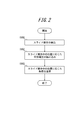
- the tactile sensation providing unit 130 provides different tactile sensations according to the position of the user's finger during the slide operation. The procedure for presenting will be described.
- the touch sensor 120 When the touch sensor 120 detects the slide operation, the touch sensor 120 outputs position information of the user's finger during the slide operation to the control unit 110 (step S101).
- the position information of the user's finger is continuously output to the control unit 110 as the user's finger moves on the touch sensor 120 from the start to the end of the slide operation.
- the control unit 110 reads information on the applied voltage to be applied to the tactile sensation providing unit 130 from the storage unit 160 in accordance with the position of the user's finger continuously received from the touch sensor 120 during the slide operation (step S102).
- the control unit 110 applies the applied voltage read from the storage unit 160 in step S102 to the tactile sensation providing unit 130.
- the tactile sensation providing unit 130 presents a tactile sensation according to the position of the slide operation on the user's finger during the slide operation (step S103). For example, when the display unit 150 displays a map, the tactile sensation providing unit 130 provides a tactile sensation according to altitude, road width, road pavement status, and the like at a location corresponding to the position of the user's finger on the map. Present.
- the tactile sensation providing apparatus 100 can present different tactile sensations during the slide operation according to the position of the user's finger on the touch sensor 120 during the slide operation when the user performs the slide operation. .
- the tactile sensation providing unit 130 presents a different tactile sensation according to altitude information at the position of the user's finger on the map displayed by the display unit 150.
- FIG. 3A is a diagram illustrating a scene in which a user starts a slide operation in which the user slides the touch sensor 120 with a finger in the navigation device.
- the display unit 150 displays a recommended route searched by the control unit 110 according to a map and a departure place and a destination set by the user.
- FIG. 3B shows the tactile sensation presented by the tactile sensation providing unit 130 during the slide operation.
- the horizontal axis corresponds to the distance that the user moved the finger by the slide operation
- the vertical axis corresponds to the altitude of the place on the map where the user is performing the slide operation. It represents the feeling of touch.
- the vertical axis in FIG. 3B corresponds to the altitude of the place on the map during the user's slide operation. That is, the tactile sensation providing unit 130 presents a tactile sensation that the user feels “high altitude” such as strong vibration when the altitude of the place on the map corresponding to the position of the user's finger is high. When the altitude of the place on the map corresponding to is low, a tactile sensation that the user feels “low altitude” such as weak vibration is presented.
- FIG. 3B illustrates a tactile sensation that the user receives according to altitude information during the slide operation shown in FIG.
- the graph shown in FIG. 3B has a gentle downward slope. This indicates that during the slide operation, the user is presented with a tactile sensation that feels that the altitude gradually decreases from the tactile sensation providing unit 130. That is, the route on the map traced by the user in the slide operation is a gentle downhill.
- the tactile sensation presented by the tactile sensation providing unit 130 may correspond to the absolute value of the altitude, or may correspond to the relative altitude from the reference based on the altitude of the place where the slide operation is started. Good.
- FIG. 3C shows a state in which the user is further performing a slide operation to the right after FIG. 3A.
- FIG. 3D illustrates the tactile sensation that the user receives according to the altitude information during the slide operation shown in FIG.
- the part following FIG. 3B of the graph shown in FIG. This indicates that during the slide operation, the user is presented with a tactile sensation that feels as the altitude increases from the tactile sensation providing unit 130. That is, following FIG. 3B, the route on the map traced by the user in the slide operation is an uphill.
- FIG. 3 (e) shows a state in which the user is performing a slide operation in the upward direction following FIG. 3 (c).
- FIG. 3 (f) illustrates the tactile sensation that the user receives according to the altitude information during the slide operation shown in FIG. 3 (e).
- the part following FIG. 3D of the graph shown in FIG. 3F is flattened after the right shoulder is lowered. This indicates that during the slide operation, the user is presented with a tactile sensation that feels that the altitude is decreasing from the tactile sensation providing unit 130, and then is presented with a tactile sensation that the altitude does not change. That is, following FIG. 3D, the route on the map that the user traced in the slide operation is flattened after the downhill.
- the altitude information corresponding to the location on the map is presented as the tactile sensation corresponding to the altitude from the tactile sensation providing unit 130, so that the user can intuitively know the altitude at the location on the map displayed by the display unit 150. Can be grasped.
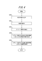
- the control unit 110 reads a map from the storage unit 160 (step S201).
- the control unit 110 displays the read map on the display unit 150 (step S202).
- the touch sensor 120 detects the slide operation, the touch sensor 120 outputs position information of the user's finger during the slide operation to the control unit 110 (step S203).
- the position information of the user's finger is continuously output to the control unit 110 as the user's finger moves on the touch sensor 120 from the start to the end of the slide operation.
- the control unit 110 should be applied from the storage unit 160 to the tactile sensation providing unit 130 according to the altitude information of the location on the map corresponding to the position of the user's finger continuously received from the touch sensor 120 during the slide operation. Information on the applied voltage is read (step S204).
- the control unit 110 applies the applied voltage read from the storage unit 160 in step S204 to the tactile sensation providing unit 130.
- the tactile sensation providing unit 130 presents a tactile sensation according to altitude information of a place on the map corresponding to the position of the slide operation on the finger of the user during the slide operation (step S205).
- FIG. 5A is a diagram illustrating a scene in which the user performs a slide operation in which the user slides the recommended route on the touch sensor 120 with a finger in the navigation device.
- the user performs a slide operation from the left to the right on the touch sensor 120.
- FIG. 5B illustrates the tactile sensation that the user receives during the slide operation of sliding along the recommended route shown in FIG.
- the graph shown in FIG. 5B rises to the right after a flat state continues for a while. This indicates that in the second half of the slide operation, the user is presented with a tactile sensation that the user feels as the altitude increases from the tactile sensation providing unit 130. That is, the recommended route on the map that the user traced in the latter half of the slide operation is an uphill.
- FIG. 5C illustrates a difference in elevation in a predetermined area where the user's finger is placed on the recommended route when the user is presented with a tactile sensation indicating that there is an uphill on the recommended route by the tactile sensation providing unit 130. It is a figure which shows the operation
- re-search action There are several actions that are suitable for the action that causes another route to be re-searched.
- FIG. 5C shows a recommended route by dragging a part of the recommended route. An example of dropping at a location off the top is shown.
- the control unit 110 when the recommended route is slid on the recommended route, the control unit 110 is smaller than the height difference in the predetermined region when the user performs a re-search operation in the predetermined region on the recommended route. Search for another route that consists only of elevation differences.
- FIG. 5D is a diagram illustrating a display on the display unit 140 when the operation illustrated in FIG. 5C is performed.
- the control unit 110 triggers the route re-search. It can be.
- control unit 110 may, for example, perform an operation in which the user moves his / her finger finely on the recommended route, or reverses the recommended route.
- the touch sensor 120 detects an action of sliding, the action may be used as a trigger for route re-search.
- FIG. 5E the control unit 110 automatically performs a re-search after the re-search operation shown in FIG. 5D is detected by the touch sensor 120, and displays another route that has been re-searched.
- FIG. 6 is a diagram showing a state displayed on a unit 150.
- the tactile sensation providing unit 130 presents a tactile sensation indicating that it is an uphill and has only a height difference smaller than the recommended route. A procedure for automatically re-searching the route by the control unit 110 will be described.
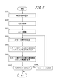
- the control unit 110 reads a map from the storage unit 160 (step S301).
- the control unit 110 displays the read map on the display unit 150 (step S302).
- the control unit 110 searches for a recommended route based on the departure place and destination input by the user, and causes the display unit 150 to display the recommended route (step S303).
- the touch sensor 120 detects a slide operation on the recommended route
- the touch sensor 120 outputs position information of the user's finger during the slide operation to the control unit 110 (step S304).
- the position information of the user's finger is continuously output to the control unit 110 as the user's finger moves on the touch sensor 120 from the start to the end of the slide operation.
- the control unit 110 applies an application to be applied from the storage unit 160 to the tactile sensation providing unit 130 according to altitude information on the recommended route corresponding to the position of the user's finger continuously received from the touch sensor 120 during the slide operation. Voltage information is read (step S305).
- the control unit 110 applies the applied voltage read from the storage unit 160 in step S305 to the tactile sensation providing unit 130.
- the tactile sensation providing unit 130 presents a tactile sensation according to altitude information of a place on the map corresponding to the position of the slide operation on the finger of the user during the slide operation (step S306).
- the touch sensor 120 detects a re-search operation in a predetermined area on the recommended route, the touch sensor 120 notifies the control unit 110 to that effect (step S307).
- the control unit 110 automatically re-searches another route having only a height difference smaller than the height difference in the predetermined area, and causes the display unit 150 to display the re-searched different route (step S308).
- the tactile sensation providing apparatus 100 can intuitively present the user with the tactile sensation presented by the tactile sensation providing unit 130 when there is an uphill on the recommended route.
- the control unit 110 automatically selects another route having only a height difference smaller than the height difference in the predetermined area in accordance with the re-search operation. Can be searched again.
- the display unit 150 and the touch sensor 120 in the description of the above embodiment are configured by an integrated device, for example, by providing both functions of the display unit 150 and the touch sensor 120 on a common substrate. Also good.
- a plurality of photoelectric conversion elements such as photodiodes are regularly arranged in a matrix electrode array of pixel electrodes included in the liquid crystal panel.
- This device displays an image with a liquid crystal panel structure, while reflecting the light of a backlight for liquid crystal display at the tip of a pen that touches and inputs a desired position on the surface of the panel. The reflected light is reflected by peripheral photoelectric conversion elements.
- the touch position can be detected by receiving the light.
Landscapes
- Engineering & Computer Science (AREA)
- General Engineering & Computer Science (AREA)
- Theoretical Computer Science (AREA)
- Human Computer Interaction (AREA)
- Physics & Mathematics (AREA)
- General Physics & Mathematics (AREA)
- User Interface Of Digital Computer (AREA)
- Position Input By Displaying (AREA)
Abstract
Description
接触を検出するタッチセンサと、
前記タッチセンサに接触する接触対象に触感を呈示する触感呈示部と、
前記タッチセンサが前記接触対象によるスライド操作を検出した場合に、連続的に触感を呈示しながら当該スライド操作中の前記接触対象の位置に応じて、当該スライド操作中の前記接触対象に異なる触感を呈示するように前記触感呈示部を制御する制御部と、
を備えることを特徴とする。
前記タッチセンサに重ねて配される、地図を表示する表示部と、
前記地図上における各場所の特性情報を含んだ地図データを記憶する記憶部と、
を備え、
前記制御部は、前記タッチセンサが前記接触対象による前記スライド操作を検出した場合に、当該スライド操作中の前記接触対象の位置に対応する前記地図上における場所の前記特性情報に応じて、当該スライド操作中の前記接触対象に異なる触感を呈示するように前記触感呈示部を制御することが望ましい。
110 制御部
120 タッチセンサ
130 触感呈示部
140 押圧検出部
150 表示部
160 記憶部
170 位置情報取得部
Claims (4)
- 接触を検出するタッチセンサと、
前記タッチセンサに接触する接触対象に触感を呈示する触感呈示部と、
前記タッチセンサが前記接触対象によるスライド操作を検出した場合に、連続的に触感を呈示しながら当該スライド操作中の前記接触対象の位置に応じて、当該スライド操作中の前記接触対象に異なる触感を呈示するように前記触感呈示部を制御する制御部と、
を備えることを特徴とする触感呈示装置。 - 請求項1に記載の触感呈示装置であって、さらに、
前記タッチセンサに重ねて配される、地図を表示する表示部と、
前記地図上における各場所の特性情報を含んだ地図データを記憶する記憶部と、
を備え、
前記制御部は、前記タッチセンサが前記接触対象による前記スライド操作を検出した場合に、当該スライド操作中の前記接触対象の位置に対応する前記地図上における場所の前記特性情報に応じて、当該スライド操作中の前記接触対象に異なる触感を呈示するように前記触感呈示部を制御すること
を特徴とする触感呈示装置。 - 請求項2に記載の触感呈示装置であって、前記特性情報は高度情報であることを特徴とする触感呈示装置。
- 請求項3に記載の触感呈示装置であって、
前記制御部は、出発地から目的地までのルートを探索し、表示する前記地図上に当該ルートを表示するように前記表示部を制御し、
前記制御部は、前記タッチセンサが前記ルート上の位置を含む所定領域において、前記接触対象による再探索動作を検出した場合に、当該所定領域における高低差よりも小さい高低差を有する領域からなる別ルートを再探索することを特徴とする触感呈示装置。
Priority Applications (2)
| Application Number | Priority Date | Filing Date | Title |
|---|---|---|---|
| JP2012554700A JP5543618B2 (ja) | 2011-01-27 | 2012-01-27 | 触感呈示装置 |
| US13/982,244 US9285881B2 (en) | 2011-01-27 | 2012-01-27 | Tactile sensation providing device |
Applications Claiming Priority (2)
| Application Number | Priority Date | Filing Date | Title |
|---|---|---|---|
| JP2011-015708 | 2011-01-27 | ||
| JP2011015708 | 2011-01-27 |
Publications (1)
| Publication Number | Publication Date |
|---|---|
| WO2012102054A1 true WO2012102054A1 (ja) | 2012-08-02 |
Family
ID=46580628
Family Applications (1)
| Application Number | Title | Priority Date | Filing Date |
|---|---|---|---|
| PCT/JP2012/000530 Ceased WO2012102054A1 (ja) | 2011-01-27 | 2012-01-27 | 触感呈示装置 |
Country Status (3)
| Country | Link |
|---|---|
| US (1) | US9285881B2 (ja) |
| JP (1) | JP5543618B2 (ja) |
| WO (1) | WO2012102054A1 (ja) |
Cited By (2)
| Publication number | Priority date | Publication date | Assignee | Title |
|---|---|---|---|---|
| JP2015032019A (ja) * | 2013-07-31 | 2015-02-16 | 株式会社ニコン | 電子機器、および電子機器の制御プログラム |
| JP2015130167A (ja) * | 2013-12-31 | 2015-07-16 | イマージョン コーポレーションImmersion Corporation | 触覚通知を提供するシステム及び方法 |
Families Citing this family (4)
| Publication number | Priority date | Publication date | Assignee | Title |
|---|---|---|---|---|
| WO2013105518A1 (ja) * | 2012-01-13 | 2013-07-18 | 京セラ株式会社 | 電子機器及び電子機器の制御方法 |
| US10168166B2 (en) * | 2015-03-13 | 2019-01-01 | Thinkware Corporation | Method and system for searching route |
| JP6613170B2 (ja) * | 2016-02-23 | 2019-11-27 | 京セラ株式会社 | 車両用コントロールユニット及びその制御方法 |
| JP2018132929A (ja) * | 2017-02-15 | 2018-08-23 | 株式会社デンソーテン | 制御装置および制御方法 |
Citations (2)
| Publication number | Priority date | Publication date | Assignee | Title |
|---|---|---|---|---|
| JP2000205878A (ja) * | 1999-01-13 | 2000-07-28 | Toyota Motor Corp | ナビゲ―ション装置、通信ナビゲ―ションシステムおよびナビゲ―ション方法 |
| JP2004309962A (ja) * | 2003-04-10 | 2004-11-04 | Denso Corp | タッチパネル付き表示装置 |
Family Cites Families (4)
| Publication number | Priority date | Publication date | Assignee | Title |
|---|---|---|---|---|
| DE102006047893A1 (de) * | 2005-12-01 | 2007-06-06 | Volkswagen Ag | Eingabevorrichtung, insbesondere für ein Kraftfahrzeug |
| JP4860283B2 (ja) | 2006-02-02 | 2012-01-25 | クラリオン株式会社 | ナビゲーション装置およびナビゲーション装置と通信する情報センタ |
| KR101502013B1 (ko) * | 2008-12-24 | 2015-03-12 | 엘지전자 주식회사 | 이동 단말기 및 이동 단말기의 위치기반서비스 제공방법 |
| KR101616875B1 (ko) * | 2010-01-07 | 2016-05-02 | 삼성전자주식회사 | 터치 패널 및 이를 구비한 전자기기 |
-
2012
- 2012-01-27 WO PCT/JP2012/000530 patent/WO2012102054A1/ja not_active Ceased
- 2012-01-27 JP JP2012554700A patent/JP5543618B2/ja active Active
- 2012-01-27 US US13/982,244 patent/US9285881B2/en active Active
Patent Citations (2)
| Publication number | Priority date | Publication date | Assignee | Title |
|---|---|---|---|---|
| JP2000205878A (ja) * | 1999-01-13 | 2000-07-28 | Toyota Motor Corp | ナビゲ―ション装置、通信ナビゲ―ションシステムおよびナビゲ―ション方法 |
| JP2004309962A (ja) * | 2003-04-10 | 2004-11-04 | Denso Corp | タッチパネル付き表示装置 |
Cited By (2)
| Publication number | Priority date | Publication date | Assignee | Title |
|---|---|---|---|---|
| JP2015032019A (ja) * | 2013-07-31 | 2015-02-16 | 株式会社ニコン | 電子機器、および電子機器の制御プログラム |
| JP2015130167A (ja) * | 2013-12-31 | 2015-07-16 | イマージョン コーポレーションImmersion Corporation | 触覚通知を提供するシステム及び方法 |
Also Published As
| Publication number | Publication date |
|---|---|
| US20130314357A1 (en) | 2013-11-28 |
| JPWO2012102054A1 (ja) | 2014-06-30 |
| US9285881B2 (en) | 2016-03-15 |
| JP5543618B2 (ja) | 2014-07-09 |
Similar Documents
| Publication | Publication Date | Title |
|---|---|---|
| RU2583754C2 (ru) | Устройство управления | |
| US9798408B2 (en) | Electronic device | |
| KR101948665B1 (ko) | 플렉서블 장치 및 그 제어 방법 | |
| CN104285205B (zh) | 触控面板器件和触控面板器件的控制方法 | |
| JP5543618B2 (ja) | 触感呈示装置 | |
| EP3382516B1 (en) | Tactile sense presentation device and tactile sense presentation method | |
| EP3422156B1 (en) | Control unit for vehicle and control method for the same | |
| US20140082490A1 (en) | User terminal apparatus for providing local feedback and method thereof | |
| JP6277786B2 (ja) | 車両用操作装置 | |
| CN104919403B (zh) | 操作装置 | |
| US20110248962A1 (en) | Information presenting device, tactile sense presenting method, and program | |
| CN105121227B (zh) | 车辆用操作装置 | |
| WO2015159774A1 (ja) | 入力装置、入力装置の制御方法 | |
| US20130300709A1 (en) | Information processing device and input device | |
| JP5697525B2 (ja) | 通信端末、サーバ、触覚フィードバック生成方法および通信システム | |
| JP6210055B2 (ja) | 情報処理システム、情報処理装置、情報処理方法 | |
| US9606651B2 (en) | Electronic device | |
| JP2011053101A (ja) | 車両現在位置表示装置及び車両現在位置表示方法 | |
| JP5801689B2 (ja) | 電子機器 | |
| JP2014010468A (ja) | 電子機器 |
Legal Events
| Date | Code | Title | Description |
|---|---|---|---|
| 121 | Ep: the epo has been informed by wipo that ep was designated in this application |
Ref document number: 12739670 Country of ref document: EP Kind code of ref document: A1 |
|
| ENP | Entry into the national phase |
Ref document number: 2012554700 Country of ref document: JP Kind code of ref document: A |
|
| WWE | Wipo information: entry into national phase |
Ref document number: 13982244 Country of ref document: US |
|
| NENP | Non-entry into the national phase |
Ref country code: DE |
|
| 122 | Ep: pct application non-entry in european phase |
Ref document number: 12739670 Country of ref document: EP Kind code of ref document: A1 |