WO2012101952A1 - Connector - Google Patents
Connector Download PDFInfo
- Publication number
- WO2012101952A1 WO2012101952A1 PCT/JP2011/080385 JP2011080385W WO2012101952A1 WO 2012101952 A1 WO2012101952 A1 WO 2012101952A1 JP 2011080385 W JP2011080385 W JP 2011080385W WO 2012101952 A1 WO2012101952 A1 WO 2012101952A1
- Authority
- WO
- WIPO (PCT)
- Prior art keywords
- connector
- plunger
- restricting
- restricted
- lock
- Prior art date
Links
Images


Classifications
-
- H—ELECTRICITY
- H01—ELECTRIC ELEMENTS
- H01R—ELECTRICALLY-CONDUCTIVE CONNECTIONS; STRUCTURAL ASSOCIATIONS OF A PLURALITY OF MUTUALLY-INSULATED ELECTRICAL CONNECTING ELEMENTS; COUPLING DEVICES; CURRENT COLLECTORS
- H01R13/00—Details of coupling devices of the kinds covered by groups H01R12/70 or H01R24/00 - H01R33/00
- H01R13/62—Means for facilitating engagement or disengagement of coupling parts or for holding them in engagement
-
- B—PERFORMING OPERATIONS; TRANSPORTING
- B60—VEHICLES IN GENERAL
- B60L—PROPULSION OF ELECTRICALLY-PROPELLED VEHICLES; SUPPLYING ELECTRIC POWER FOR AUXILIARY EQUIPMENT OF ELECTRICALLY-PROPELLED VEHICLES; ELECTRODYNAMIC BRAKE SYSTEMS FOR VEHICLES IN GENERAL; MAGNETIC SUSPENSION OR LEVITATION FOR VEHICLES; MONITORING OPERATING VARIABLES OF ELECTRICALLY-PROPELLED VEHICLES; ELECTRIC SAFETY DEVICES FOR ELECTRICALLY-PROPELLED VEHICLES
- B60L53/00—Methods of charging batteries, specially adapted for electric vehicles; Charging stations or on-board charging equipment therefor; Exchange of energy storage elements in electric vehicles
- B60L53/10—Methods of charging batteries, specially adapted for electric vehicles; Charging stations or on-board charging equipment therefor; Exchange of energy storage elements in electric vehicles characterised by the energy transfer between the charging station and the vehicle
- B60L53/14—Conductive energy transfer
- B60L53/16—Connectors, e.g. plugs or sockets, specially adapted for charging electric vehicles
-
- H—ELECTRICITY
- H01—ELECTRIC ELEMENTS
- H01R—ELECTRICALLY-CONDUCTIVE CONNECTIONS; STRUCTURAL ASSOCIATIONS OF A PLURALITY OF MUTUALLY-INSULATED ELECTRICAL CONNECTING ELEMENTS; COUPLING DEVICES; CURRENT COLLECTORS
- H01R13/00—Details of coupling devices of the kinds covered by groups H01R12/70 or H01R24/00 - H01R33/00
- H01R13/62—Means for facilitating engagement or disengagement of coupling parts or for holding them in engagement
- H01R13/627—Snap or like fastening
- H01R13/6275—Latching arms not integral with the housing
-
- H—ELECTRICITY
- H01—ELECTRIC ELEMENTS
- H01R—ELECTRICALLY-CONDUCTIVE CONNECTIONS; STRUCTURAL ASSOCIATIONS OF A PLURALITY OF MUTUALLY-INSULATED ELECTRICAL CONNECTING ELEMENTS; COUPLING DEVICES; CURRENT COLLECTORS
- H01R13/00—Details of coupling devices of the kinds covered by groups H01R12/70 or H01R24/00 - H01R33/00
- H01R13/62—Means for facilitating engagement or disengagement of coupling parts or for holding them in engagement
- H01R13/639—Additional means for holding or locking coupling parts together, after engagement, e.g. separate keylock, retainer strap
- H01R13/6397—Additional means for holding or locking coupling parts together, after engagement, e.g. separate keylock, retainer strap with means for preventing unauthorised use
-
- B—PERFORMING OPERATIONS; TRANSPORTING
- B60—VEHICLES IN GENERAL
- B60L—PROPULSION OF ELECTRICALLY-PROPELLED VEHICLES; SUPPLYING ELECTRIC POWER FOR AUXILIARY EQUIPMENT OF ELECTRICALLY-PROPELLED VEHICLES; ELECTRODYNAMIC BRAKE SYSTEMS FOR VEHICLES IN GENERAL; MAGNETIC SUSPENSION OR LEVITATION FOR VEHICLES; MONITORING OPERATING VARIABLES OF ELECTRICALLY-PROPELLED VEHICLES; ELECTRIC SAFETY DEVICES FOR ELECTRICALLY-PROPELLED VEHICLES
- B60L2270/00—Problem solutions or means not otherwise provided for
- B60L2270/30—Preventing theft during charging
- B60L2270/32—Preventing theft during charging of electricity
-
- B—PERFORMING OPERATIONS; TRANSPORTING
- B60—VEHICLES IN GENERAL
- B60L—PROPULSION OF ELECTRICALLY-PROPELLED VEHICLES; SUPPLYING ELECTRIC POWER FOR AUXILIARY EQUIPMENT OF ELECTRICALLY-PROPELLED VEHICLES; ELECTRODYNAMIC BRAKE SYSTEMS FOR VEHICLES IN GENERAL; MAGNETIC SUSPENSION OR LEVITATION FOR VEHICLES; MONITORING OPERATING VARIABLES OF ELECTRICALLY-PROPELLED VEHICLES; ELECTRIC SAFETY DEVICES FOR ELECTRICALLY-PROPELLED VEHICLES
- B60L2270/00—Problem solutions or means not otherwise provided for
- B60L2270/30—Preventing theft during charging
- B60L2270/34—Preventing theft during charging of parts
-
- H—ELECTRICITY
- H01—ELECTRIC ELEMENTS
- H01R—ELECTRICALLY-CONDUCTIVE CONNECTIONS; STRUCTURAL ASSOCIATIONS OF A PLURALITY OF MUTUALLY-INSULATED ELECTRICAL CONNECTING ELEMENTS; COUPLING DEVICES; CURRENT COLLECTORS
- H01R13/00—Details of coupling devices of the kinds covered by groups H01R12/70 or H01R24/00 - H01R33/00
- H01R13/66—Structural association with built-in electrical component
- H01R13/6608—Structural association with built-in electrical component with built-in single component
- H01R13/6633—Structural association with built-in electrical component with built-in single component with inductive component, e.g. transformer
-
- H—ELECTRICITY
- H01—ELECTRIC ELEMENTS
- H01R—ELECTRICALLY-CONDUCTIVE CONNECTIONS; STRUCTURAL ASSOCIATIONS OF A PLURALITY OF MUTUALLY-INSULATED ELECTRICAL CONNECTING ELEMENTS; COUPLING DEVICES; CURRENT COLLECTORS
- H01R2201/00—Connectors or connections adapted for particular applications
- H01R2201/26—Connectors or connections adapted for particular applications for vehicles
-
- Y—GENERAL TAGGING OF NEW TECHNOLOGICAL DEVELOPMENTS; GENERAL TAGGING OF CROSS-SECTIONAL TECHNOLOGIES SPANNING OVER SEVERAL SECTIONS OF THE IPC; TECHNICAL SUBJECTS COVERED BY FORMER USPC CROSS-REFERENCE ART COLLECTIONS [XRACs] AND DIGESTS
- Y02—TECHNOLOGIES OR APPLICATIONS FOR MITIGATION OR ADAPTATION AGAINST CLIMATE CHANGE
- Y02T—CLIMATE CHANGE MITIGATION TECHNOLOGIES RELATED TO TRANSPORTATION
- Y02T10/00—Road transport of goods or passengers
- Y02T10/60—Other road transportation technologies with climate change mitigation effect
- Y02T10/70—Energy storage systems for electromobility, e.g. batteries
-
- Y—GENERAL TAGGING OF NEW TECHNOLOGICAL DEVELOPMENTS; GENERAL TAGGING OF CROSS-SECTIONAL TECHNOLOGIES SPANNING OVER SEVERAL SECTIONS OF THE IPC; TECHNICAL SUBJECTS COVERED BY FORMER USPC CROSS-REFERENCE ART COLLECTIONS [XRACs] AND DIGESTS
- Y02—TECHNOLOGIES OR APPLICATIONS FOR MITIGATION OR ADAPTATION AGAINST CLIMATE CHANGE
- Y02T—CLIMATE CHANGE MITIGATION TECHNOLOGIES RELATED TO TRANSPORTATION
- Y02T10/00—Road transport of goods or passengers
- Y02T10/60—Other road transportation technologies with climate change mitigation effect
- Y02T10/7072—Electromobility specific charging systems or methods for batteries, ultracapacitors, supercapacitors or double-layer capacitors
-
- Y—GENERAL TAGGING OF NEW TECHNOLOGICAL DEVELOPMENTS; GENERAL TAGGING OF CROSS-SECTIONAL TECHNOLOGIES SPANNING OVER SEVERAL SECTIONS OF THE IPC; TECHNICAL SUBJECTS COVERED BY FORMER USPC CROSS-REFERENCE ART COLLECTIONS [XRACs] AND DIGESTS
- Y02—TECHNOLOGIES OR APPLICATIONS FOR MITIGATION OR ADAPTATION AGAINST CLIMATE CHANGE
- Y02T—CLIMATE CHANGE MITIGATION TECHNOLOGIES RELATED TO TRANSPORTATION
- Y02T90/00—Enabling technologies or technologies with a potential or indirect contribution to GHG emissions mitigation
- Y02T90/10—Technologies relating to charging of electric vehicles
- Y02T90/14—Plug-in electric vehicles
Definitions
- the present invention relates to a connector used for supplying electric power to, for example, an electric vehicle.
- the connector used for power supply is provided with a power supply pin or a power supply contact for supplying a large current.
- a large current flows from the connector to the mating connector fitted with the connector through the power pins or the power contacts. It is very dangerous if the mating state in which the connector and the mating connector are mated is released during power feeding. Therefore, this type of connector is usually provided with a mechanism that prevents the fitted state from being released during power feeding.
- Patent Document 1 A connector provided with the above-described mechanism is disclosed in Patent Document 1 or Patent Document 2, for example.
- the contents of this publication are incorporated herein by reference.
- the connector of Patent Document 1 includes a push-type solenoid having an electromagnetic coil and a plunger driven by the electromagnetic coil.
- the connector further includes an operation lever that can be operated to release the fitted state.
- a hole is formed in the operation lever.
- the electromagnetic coil drives the plunger to project a predetermined amount.
- the protruding portion of the plunger is inserted into the hole of the operating lever, thereby preventing the operating lever from being operated.
- the connector of Patent Document 2 includes a push-type solenoid similar to the push-type solenoid of Patent Document 1 and a release lever having a hole formed therein.
- the plunger is inserted into the hole of the release lever to prevent the release lever from displacing, thereby preventing unintentional release of the fitted state.
- the shape and size of the hole provided in the lever must be adjusted to be approximately the same as the shape and size of the plunger. I must. Otherwise, the lever will rattle when the plunger is inserted into the hole.
- the hole must be accurately aligned with the plunger.
- the solenoid drives the plunger, if the position of the lever hole is slightly away from the plunger, the plunger may not be inserted into the hole. Therefore, there is a possibility that the connector is not properly locked even when power is supplied.
- an object of the present invention is to provide a connector configured to more reliably lock the fitting state with the mating connector.
- the connector includes a lock member, a solenoid, a regulating member, and a regulated portion.
- the locking member is configured to engage with the mating connector in a mating state in which the connector and the mating connector are fitted to each other, thereby locking the mating state.
- the solenoid has a plunger.
- the solenoid is configured to drive the plunger between a restriction position and a release position along a predetermined direction.
- the restricting member has a restricting portion extending in an intersecting direction intersecting the predetermined direction. The restriction member is supported by the plunger so as to be moved by the plunger.
- the restricted portion is configured to receive the restricting portion along the predetermined direction when the plunger is driven from the release position to the restricted position.
- the restriction part restricts the movement of the restricted part, whereby the restricted part directly or indirectly indicates that the fitting state is unlocked. To prevent.
- the restricting portion extending in the direction intersecting the predetermined direction is received by the restricted portion along the predetermined direction. Therefore, what is received by the regulated portion is not the protruding end face of the regulating portion but the side portion.
- the restriction portion can be easily received by the restricted portion by making the side portion of the restriction portion relatively larger than the restricted portion in the crossing direction. be able to. Furthermore, in the crossing direction and the direction orthogonal to the predetermined direction (that is, the direction in which movement of the restricted portion is desired to be restricted at the time of locking: movement restriction direction), for example, the size of the restricted portion and the size of the restricted portion are substantially the same By doing so, the restricting portion received by the restricted portion can be stably held. Therefore, according to this invention, a fitting state with the other party connector can be locked more reliably.
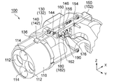
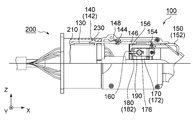
- FIG. 1 It is a perspective view which shows the connector by embodiment of this invention. It is a partially cutaway side view which shows the principal part of the connector of FIG. It is a perspective view which shows the connector of FIG. 1 in the state which has a plunger in a releasing position.
- the second shell, the power supply contact (contact), the signal contact (contact) and the wires connected to these contacts are disconnected from the connector.
- the connector of FIG. 3 it is a perspective view which shows the connector of FIG. 3 in the state which has a plunger in a control position.
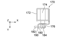
- FIG. 1 It is a perspective view which shows the unit which consists of the solenoid of the connector of FIG. 1, a control member, and a guide plate in the state in which a plunger exists in a releasing position.
- FIG. 6 is a top view showing the unit of FIG. 5.
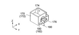
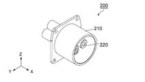
- FIG. 7 is a perspective view showing the unit of FIG. 5 with the plunger in the restricted position. It is a front view which shows the to-be-controlled part and control member of the connector of FIG. It is a front view which shows the modification of the to-be-regulated part of FIG. It is a perspective view which shows the other party connector which can be fitted with the connector of FIG. It is sectional drawing which shows the other party connector of FIG. 10 along the center axis
- FIG. 11 is a partially cutaway side view showing the connector of FIG. 1 and the mating connector of FIG. 10. Here, the connector and the mating connector are in the fitting process.
- FIG. 11 is a partially cutaway side view showing the connector of FIG.
- FIG. 11 is a partially cutaway side view showing the connector of FIG. 1 and the mating connector of FIG. 10. Here, the connector and the mating connector are in the process of being removed.
- the connector 100 is a power supply side plug connector.
- the connector 100 can be fitted to, for example, a mating connector (power-receiving-side receptacle connector) 200 (see FIGS. 10 and 11) mounted on an electric vehicle along the X direction (fitting direction).
- a mating connector power-receiving-side receptacle connector 200 (see FIGS. 10 and 11) mounted on an electric vehicle along the X direction (fitting direction).
- the mating connector 200 includes a housing 210 made of an insulator, a plurality of power receiving contacts 220, and a plurality of signal contacts 240.
- the power receiving contact 220 and the signal contact 240 are held by the housing 210.
- Each of the signal contacts 240 is connected to the signal line 250.
- the mating connector 200 is further formed with an inner wall 212 and a locking portion 230.
- the inner wall 212 is formed at the end on the + X side inside the housing 210.
- the locking portion 230 according to the present embodiment is a step formed inside the housing 210 so as to be adjacent to the inner wall 212. In other words, the inner wall 212 protrudes from the locking portion 230 toward the central axis of the housing 210.
- the connector 100 includes a housing 110 made of an insulator, a plurality of signal contacts 120, a plurality of power supply contacts (not shown), a shell 130, A lock member (lock lever) 140, a release operation member (release lever) 150, a regulated portion 160, a solenoid 170, a regulating member 180, and a guide plate 190 are provided.
- the signal contact 120 and the power supply contact (not shown) are held in the housing 110.
- Shell 130 is an outer shell of connector 100.
- the lock member 140 is configured to engage with the mating connector 200 in a mated state in which the connector 100 and the mating connector 200 are fitted to each other (see FIG. 13), thereby locking the mating state. .
- the release operation member 150 can be displaced so as to release the engagement of the lock member 140 with the mating connector 200 (see FIG. 14), thereby unlocking the fitted state.
- the restricted portion 160 according to the present embodiment is provided on the release operation member 150.
- the regulated portion 160 may be provided on another member.
- the restricted portion 160 may be formed on the lock member 140.
- the solenoid 170 functions as an electromagnetic lock that locks the release operation member 150 so that it cannot be displaced. More specifically, the restricting member 180 is displaced by the solenoid 170 in the fitted state, thereby restricting the movement of the restricted portion 160.
- the guide plate 190 is configured to guide the regulating member 180 displaced by the solenoid 170 toward the regulated portion 160.
- the housing 110 has a substantially cylindrical shape extending along a central axis parallel to the X direction, and thus has an end portion (front end) on the ⁇ X side.
- the housing 110 is formed with a holding hole 112 for holding a power supply contact (not shown) and a holding hole 114 (see FIG. 2) for holding the signal contact 120.
- Each of the holding hole 112 and the holding hole 114 extends rearward from the front end (fitting end).
- the power supply contact (not shown) is configured to flow a large current by being connected to the power receiving contact 220 in the fitted state.
- the signal contact 120 is configured to be connected to the signal contact 240 and transmit a signal in the fitted state.
- the shell 130 includes a first shell 132 and a second shell 134 each having a substantially half-pipe shape.
- the first shell 132 and the second shell 134 are connected to each other to form the shell 130.
- the second shell 134 is screwed to the first shell 132, and the shell 130 is connected to the first shell 132 and the second shell by a surface passing through the central axis of the housing 110. It can be divided into shells 134.
- the housing 110 holding the signal contact 120 and the power supply contact includes the lock member 140, the release operation member 150, and the restriction member.
- the first shell 132 is incorporated.
- the second shell 134 is attached to the first shell 132 so as to cover the above-described member from the side.
- an opening 136 is formed in the shell 130.
- the opening 136 is provided in a portion of the shell 130 to be inserted into the housing 210 of the mating connector 200 in the fitted state.
- the connector 100 includes a grip 138 that is gripped by an operator when power is supplied.
- the grip 138 is formed behind the shell 130.
- the lock member 140 has a lock portion 142, a lock shaft portion 144, and a pressed portion 146.
- the lock member 140 is held by the shell 130 so as to be rotatable around the lock shaft portion 144.
- the lock part 142 is configured to lock the fitting state between the connector 100 and the mating connector 200.
- the lock member 140 has a front end (that is, an end portion on the ⁇ X side) and a rear end (that is, an end portion on the + X side) at both ends in the X direction.
- the lock portion 142 is formed at the front end of the lock member 140 and has a hook-shaped cross section formed so as to protrude upward.
- a spring 148 is attached to the lock member 140.
- the spring 148 always urges the lock portion 142 upward, so that the lock portion 142 protrudes upward beyond the opening 136.
- the hook of the lock portion 142 that has passed through the opening 136 of the shell 130 is locked to the locking portion 230 of the mating connector 200 in the fitted state, thereby locking the fitted state (see FIGS. 2 and 13). ).
- the pressed portion 146 is formed at the rear end of the lock member 140, and the lock shaft portion 144 is located between the lock portion 142 and the pressed portion 146 in the X direction. As understood from the above description, when the pressed part 146 is pushed upward and moved, the lock part 142 moves downward.
- the release operation member 150 includes an operated portion 152, an operation shaft portion 154, and a pressing portion 156.
- the release operation member 150 is held by the shell 130 so as to be rotatable around the operation shaft portion 154.
- the release operation member 150 has a front end (that is, an end portion on the ⁇ X side) and a rear end (that is, an end portion on the + X side) at both ends in the X direction.
- the operated portion 152 is formed at the rear end of the release operation member 150.
- the operated portion 152 projects outward from the shell 130 at the top of the grip 138 and can be pressed by the operator.
- the pressing portion 156 is formed at the front end of the release operation member 150.
- the release operation member 150 has a front end that functions as the pressing portion 156.
- the operation shaft portion 154 is located between the operated portion 152 and the pressing portion 156 in the X direction.
- the pressing part 156 according to the present embodiment is located below the pressed part 146. Accordingly, when the operated portion 152 is operated and moved downward, the pressing portion 156 presses the pressed portion 146 upward. As a result, the lock part 142 moves downward, whereby the engagement of the lock part 142 with the mating connector 200 is released (that is, the fitted state is unlocked).
- the front end of the release operation member 150 according to the present embodiment extends along the ⁇ Z direction, and a portion extending downward is formed at the front end of the release operation member 150.
- a regulated portion 160 is formed in a portion extending downward.
- the regulated portion 160 according to the present embodiment is a concave portion that is recessed in the ⁇ Y direction.
- the restricted portion 160 according to the present embodiment is placed closer to the pressing portion 156 than the operation shaft portion 154. In other words, the distance between the restricted portion 160 and the pressing portion 156 is shorter than the distance between the restricted portion 160 and the operation shaft portion 154. More specifically, the pressing portion 156 according to the present embodiment is located between the restricted portion 160 and the operation shaft portion 154 in the X direction. Therefore, the movement of the pressing portion 156 in the Z direction can be restricted by a relatively small force applied to the restricted portion 160.
- the regulated portion 160 according to the present embodiment is provided such that the fitted state is unlocked by the movement of the regulated portion 160 along the Z direction (movement regulation direction).
- the movement of the restricted portion 160 in the Z direction is restricted, the movement of the pressing portion 156 along the + Z direction (that is, the rising of the pressing portion 156) is restricted, thereby preventing the unlocking of the fitted state.
- connector 100 further includes guide portion 162.
- the restricted portion 160 according to the present embodiment is a space surrounded by a vertical wall, a top wall, and a bottom wall. The top wall and the bottom wall face each other in the Z direction.
- Edges on the + Y side of the top wall and the bottom wall are chamfered, whereby the regulated portion 160 is provided with a guide portion 162.
- Each of the guide parts 162 extends so as to be oblique to both the Y direction (predetermined direction) and the Z direction.
- the solenoid 170 includes a frame 172, an electromagnetic coil 174, and a plunger 176.
- the solenoid 170 is configured to drive the plunger 176 along a Y direction between a restriction position (see FIGS. 4 and 7) and a release position (see FIGS. 3, 5 and 6). More specifically, the electromagnetic coil 174 is held by the frame 172 so that it is energized (ie, activated) when the connector 100 supplies power to the mating connector 200. .
- the activated electromagnetic coil 174 drives the plunger 176 between the release position and the restriction position along the Y direction.
- the solenoid 170 according to the present embodiment is a so-called pull-type solenoid.
- the release position of the plunger 176 is located outside the restricting position in the Y direction. In other words, as compared with the plunger 176 at the restriction position, the plunger 176 at the release position protrudes outward in the Y direction. On the other hand, the plunger 176 at the restriction position is retracted inward in the Y direction. For this reason, all the members (for example, the lock member 140, the release operation member 150, and the solenoid 170) related to the lock in the fitted state are in a state in which the above-described members can operate without the second shell 134. 132 can be attached.
- the connector 100 is not provided with a structure that can operate only when the first shell 132 and the second shell 134 are connected to each other.
- the connector 100 including the pull-type solenoid can be assembled by covering the first shell 132 to which the member related to the lock in the fitted state is attached with the second shell 134. Therefore, the connector 100 can be assembled more easily.
- pull-type solenoids are more common and so available than so-called push-type solenoids.
- the plunger 176 is formed with a holding hole 178 that penetrates the plunger 176 in the X direction (cross direction).
- the restricting member 180 is inserted into the holding hole 178 and supported.
- the restriction member 180 according to the present embodiment includes a restriction portion 182 and a supported portion 184 that extend in the X direction, and thereby has a rod-like shape that extends in the X direction.
- the supported portion 184 is inserted and held in the holding hole 178 (see FIGS. 5 and 6).
- the extending direction in which the regulating member 180 extends (that is, the through direction in which the holding hole 178 passes through the plunger 176) is orthogonal to the Y direction.
- the intersecting direction (X direction) intersects the predetermined direction (Y direction) at a right angle.
- the extending direction (penetration direction) may not be orthogonal to the Y direction as long as it intersects the Y direction.
- the restricting portion 182 has a circular cross section in the YZ plane.
- the diameter of the circular cross section of the restricting portion 182 is substantially equal to the size of the restricted portion 160 in the Z direction (movement restricting direction).
- the regulating member 180 extends in the X direction while being supported by the plunger 176. In the X direction, the size of the portion that can function as the restricting portion 182 of the restricting member 180 is larger than the size of the restricted portion 160.
- the regulating member 180 moves along the Y direction according to the driving of the plunger 176.
- the restriction member 180 is supported by the plunger 176 so as to be moved by the plunger 176.
- the plunger 176 driven by the solenoid 170 may move along its Y axis and rotate about its own axis extending in the Y direction. Therefore, the regulating member 180 supported by the plunger 176 may rotate around the plunger 176 as an axis.
- a guide plate 190 is provided, whereby the restricting portion 182 of the restricting member 180 moves reliably along the Y direction.
- the guide plate 190 guides the restriction portion 182 along the Y direction when the plunger 176 driven by the solenoid 170 moves the restriction portion 182.
- the regulating member 180 is separated from the regulated portion 160. Therefore, when the plunger 176 is in the release position, the restriction portion 182 of the restriction member 180 does not hinder the movement of the restricted portion 160.
- the regulated portion 160 is configured to receive the regulating portion 182 along the Y direction when the plunger 176 is driven from the release position to the regulated position (see FIG. 4). More specifically, according to the driving of the plunger 176, not the end face in the X direction of the restriction portion 182 but the side surface of the restriction portion 182 is received by the restricted portion 160.
- the release operation member 150 is provided with the guide portion 162 obliquely intersecting in both the Y direction and the Z direction, the position of the restriction portion 182 in the Z direction is the Z of the restricted portion 160. Even if the position is slightly above or below the position in the direction, the restricting portion 182 guided by the guide portion 162 is received in the restricted portion 160.
- the guide portion 162 is configured such that the restricting portion 182 is guided by the guide portion 162 and received by the restricted portion 160. According to the present embodiment, it is possible to reliably prevent the fitting state from being unlocked without accurately matching the position of the restricting portion 182 in the Z direction with the position of the restricted portion 160 in the Z direction. .
- the restricting portion 182 received by the restricted portion 160 restricts the displacement of the release operation member 150, thereby disabling the operation of displacing the release operation member 150.
- the restricted portion 160 indirectly prevents the fitting state from being unlocked.
- the regulated portion 160 is provided on the lock member 140, it is possible to directly prevent the fitting state from being unlocked.
- the restricting portion 182 restricts the movement of the restricted portion 160, whereby the restricted portion 160 is unlocked from the fitted state (that is, by the lock member 140). The lock is released directly or indirectly.
- the restricting portion 182 according to the present embodiment is longer than the restricted portion 160 in the X direction, and thus the restricted portion 160 can receive the restricting portion 182 more reliably. Furthermore, the restricting portion 182 has substantially the same size as the restricted portion 160 in the Z direction, and therefore the restricted portion 160 holds the received restricting portion 182 more stably. In other words, the size and shape of the restricted portion 160 according to the present embodiment in the Z direction effectively move the restricted portion 160 in the Z direction when the restricted portion 182 is received by the restricted portion 160. It is formed to prevent.
- the height (that is, the size in the Z direction) of the restricted portion 160 is constant along the Y direction.
- the height of the regulated portion 160 may vary along the Y direction.
- the connector 100 may include a release operation member 150 a instead of the release operation member 150.
- the release operation member 150a includes guide portions 162a that face each other in the Z direction.
- the guide portion 162a is a slope that is orthogonal to both the Y direction and the Z direction.
- the release operation member 150a has a recess that functions as the restricted portion 160a.
- the restricted portion 160a is a recess located between two inclined surfaces that continuously extend from the guide portion 162a.
- the regulated portion 160a is formed so that the size in the Z direction decreases as the position in the Y direction approaches the back wall of the regulated portion 160a.
- the regulated portion 160a configured in this way can reliably hold the regulating member 180 even if the diameter of the regulating member 180 is changed by, for example, a design change. Therefore, the restricted portion 160a can more appropriately prevent the locked state of the fitting state from being released (that is, the fitting state is unlocked).
- the locking portion 142 of the locking member 140 receives a downward force from the mating connector 200. Accordingly, the lock portion 142 moves downward from the initial position while resisting the upward force received from the spring 148.
- the lock part 142 moves inside the housing 210 and slides on the inner wall 212 of the housing 210.
- the connector 100 and the mating connector 200 are completely fitted.
- the connector 100 and the mating connector 200 transition to the fitted state.
- the lock part 142 reaches the locking part 230 beyond the inner wall 212 in the X direction.
- the lock part 142 urged upward by the spring 148 returns to the initial position.
- the fitted state is locked. Specifically, even when the connector 100 is pulled from the mating connector 200, the connector 100 cannot be removed from the mating connector 200 because the locking portion 142 is locked to the locking portion 230.
- the plunger 176 is driven to the restricted position by the solenoid 170.
- the restricting portion 182 supported by the plunger 176 is received in the restricted portion 160 (or the restricted portion 160a), and thereby the displacement of the release operation member 150 is restricted.
- the fitting state is not unlocked.
- the solenoid 170 is deactivated, whereby the plunger 176 returns to the release position.
- the restricting portion 182 comes out of the restricted portion 160 (or restricted portion 160a), so that the release operation member 150 can be displaced (that is, the fitted state can be unlocked).
- the release operation member 150 is displaced while the plunger 176 is in the release position, the locking of the lock member 140 with respect to the mating connector 200 is released.
- the operated portion 152 is pushed down, the pressing portion 156 pushes up the pressed portion 146, thereby moving the lock portion 142 downward.
- the locking of the locking part 142 with respect to the locking part 230 is released, and the connector 100 can be removed from the mating connector 200.
- the fitting direction is the X direction
- the predetermined direction is the Y direction orthogonal to the fitting direction.
- the relationship between the fitting direction and the predetermined direction is not limited to the above-described embodiment.
- the fitting direction and the predetermined direction may be parallel to each other.
- the plunger 176 and the regulating member 180 are members separated from each other.
- the plunger 176 and the regulating member 180 may be integrally formed.
- the present invention is based on Japanese Patent Application No. 2011-14781 filed with the Japan Patent Office on January 27, 2011, the contents of which are incorporated herein by reference.
Landscapes
- Engineering & Computer Science (AREA)
- Computer Security & Cryptography (AREA)
- Power Engineering (AREA)
- Transportation (AREA)
- Mechanical Engineering (AREA)
- Details Of Connecting Devices For Male And Female Coupling (AREA)
Abstract
A connector capable of being fitted to a partner connector is provided with a lock member, a solenoid having a plunger, a restriction member having a restricting part, and a restricted part. In a fitted state in which the connector and the partner connector are fitted to each other, the lock member engages the partner connector and locks the two connectors into a fitted state. The solenoid drives the plunger between a restriction position and a release position. The restriction member is movably supported by the plunger. The restricted part receives the restricting part when the plunger is driven into the restriction position. When the plunger is in the restriction position, movement of the restricted part is restricted by the restricting part, and thereby the restricted part directly or indirectly prevents release of the fitted state.
Description
本発明は、電力を例えば電気自動車に供給するために用いられるコネクタに関する。
The present invention relates to a connector used for supplying electric power to, for example, an electric vehicle.
給電に用いられるコネクタには、大電流を供給するための電源ピン又は電源コンタクトが設けられている。給電の際、コネクタからコネクタと嵌合した相手側コネクタまで、電源ピン又は電源コンタクトを通して大電流が流れている。コネクタと相手側コネクタとが嵌合している嵌合状態が給電中に解除されると非常に危険である。そのため、この種のコネクタには、通常、嵌合状態が給電中に解除されることを防止する機構が設けられている。
The connector used for power supply is provided with a power supply pin or a power supply contact for supplying a large current. During power feeding, a large current flows from the connector to the mating connector fitted with the connector through the power pins or the power contacts. It is very dangerous if the mating state in which the connector and the mating connector are mated is released during power feeding. Therefore, this type of connector is usually provided with a mechanism that prevents the fitted state from being released during power feeding.
上述した機構が設けられたコネクタは、例えば、特許文献1又は特許文献2に開示されている。当該公報の内容は参照することにより本明細書の一部をなす。特許文献1のコネクタは、電磁コイルと電磁コイルによって駆動されるプランジャとを有するプッシュ型のソレノイドを備えている。コネクタは、嵌合状態を解除するために操作可能な操作レバーを更に備えている。操作レバーには、穴が形成されている。給電の際、電磁コイルがプランジャを駆動して所定量突出させる。給電の際、プランジャの突出した部位が操作レバーの穴に挿入され、これによって、操作レバーが操作されることを防止する。特許文献2のコネクタは、特許文献1のプッシュ型ソレノイドと同様なプッシュ型ソレノイドと、穴が形成された解除レバーとを備えている。給電の際、プランジャが解除レバーの穴に挿入されて解除レバーが変位することを防止し、これによって嵌合状態の意図しない解除が防止される。
A connector provided with the above-described mechanism is disclosed in Patent Document 1 or Patent Document 2, for example. The contents of this publication are incorporated herein by reference. The connector of Patent Document 1 includes a push-type solenoid having an electromagnetic coil and a plunger driven by the electromagnetic coil. The connector further includes an operation lever that can be operated to release the fitted state. A hole is formed in the operation lever. During power feeding, the electromagnetic coil drives the plunger to project a predetermined amount. During power feeding, the protruding portion of the plunger is inserted into the hole of the operating lever, thereby preventing the operating lever from being operated. The connector of Patent Document 2 includes a push-type solenoid similar to the push-type solenoid of Patent Document 1 and a release lever having a hole formed therein. During power feeding, the plunger is inserted into the hole of the release lever to prevent the release lever from displacing, thereby preventing unintentional release of the fitted state.
レバー(操作レバー又は解除レバー)が操作されたり変位したりすることを確実に防止するためには、レバーに設けられた穴の形状及びサイズを、プランジャの形状及びサイズとほぼ同じに調整しなければならない。さもないと、プランジャが穴に挿入されたときレバーがガタついてしまう。
To ensure that the lever (control lever or release lever) is not operated or displaced, the shape and size of the hole provided in the lever must be adjusted to be approximately the same as the shape and size of the plunger. I must. Otherwise, the lever will rattle when the plunger is inserted into the hole.
しかしながら、レバーの穴の形状及びサイズとプランジャの形状及びサイズとがほぼ同じ場合、穴をプランジャと正確に位置合わせしなければならない。ソレノイドがプランジャを駆動する際に、レバーの穴の位置がプランジャから少し離れていると、プランジャが穴に挿入されないおそれがある。従って、給電時にもかかわらずコネクタの嵌合状態が適切にロックされないおそれがある。
However, when the shape and size of the lever hole and the shape and size of the plunger are substantially the same, the hole must be accurately aligned with the plunger. When the solenoid drives the plunger, if the position of the lever hole is slightly away from the plunger, the plunger may not be inserted into the hole. Therefore, there is a possibility that the connector is not properly locked even when power is supplied.
そこで、本発明は、相手側コネクタとの嵌合状態を、より確実にロックするように構成されたコネクタを提供することを目的とする。
Therefore, an object of the present invention is to provide a connector configured to more reliably lock the fitting state with the mating connector.
本発明の一側面は、相手側コネクタと嵌合可能なコネクタを提供する。前記コネクタは、ロック部材と、ソレノイドと、規制部材と、被規制部とを備えている。前記ロック部材は、前記コネクタと前記相手側コネクタとが互いに嵌合した嵌合状態において前記相手側コネクタに係合するように構成されており、これによって前記嵌合状態をロックする。前記ソレノイドは、プランジャを有している。前記ソレノイドは、所定方向に沿って規制位置と解除位置との間で前記プランジャを駆動するように構成されている。前記規制部材は、前記所定方向と交差する交差方向に延びる規制部を有している。前記規制部材は、前記プランジャによって移動させられるようにして前記プランジャに支持されている。前記被規制部は、前記プランジャが前記解除位置から前記規制位置まで駆動された際、前記規制部を前記所定方向に沿って受容するように構成されている。前記プランジャが前記規制位置にあるとき、前記規制部によって前記被規制部の移動が規制され、これによって前記被規制部は、前記嵌合状態がアンロックされることを直接的に又は間接的に防止する。
One aspect of the present invention provides a connector that can be mated with a mating connector. The connector includes a lock member, a solenoid, a regulating member, and a regulated portion. The locking member is configured to engage with the mating connector in a mating state in which the connector and the mating connector are fitted to each other, thereby locking the mating state. The solenoid has a plunger. The solenoid is configured to drive the plunger between a restriction position and a release position along a predetermined direction. The restricting member has a restricting portion extending in an intersecting direction intersecting the predetermined direction. The restriction member is supported by the plunger so as to be moved by the plunger. The restricted portion is configured to receive the restricting portion along the predetermined direction when the plunger is driven from the release position to the restricted position. When the plunger is in the restriction position, the restriction part restricts the movement of the restricted part, whereby the restricted part directly or indirectly indicates that the fitting state is unlocked. To prevent.
本発明によるコネクタにおいては、所定方向と交差する方向(交差方向)に延びる規制部が、所定方向に沿って被規制部に受容される。従って、被規制部に受容されるのは、規制部の突端面ではなく側部である。
In the connector according to the present invention, the restricting portion extending in the direction intersecting the predetermined direction (intersection direction) is received by the restricted portion along the predetermined direction. Therefore, what is received by the regulated portion is not the protruding end face of the regulating portion but the side portion.
本発明によるコネクタは、上記のように構成されているので、交差方向において規制部の側部を被規制部に対して相対的に大きくすることにより、規制部を被規制部に受容させやすくすることができる。更に、交差方向及び所定方向と直交する方向(即ち、ロック時において被規制部の移動を規制したい方向:移動規制方向)において、例えば規制部のサイズと被規制部のサイズとを実質的に同一にすることにより、被規制部に受容された規制部を安定的に保持することができる。従って、本発明によれば、相手側コネクタとの嵌合状態を、より確実にロックすることができる。
Since the connector according to the present invention is configured as described above, the restriction portion can be easily received by the restricted portion by making the side portion of the restriction portion relatively larger than the restricted portion in the crossing direction. be able to. Furthermore, in the crossing direction and the direction orthogonal to the predetermined direction (that is, the direction in which movement of the restricted portion is desired to be restricted at the time of locking: movement restriction direction), for example, the size of the restricted portion and the size of the restricted portion are substantially the same By doing so, the restricting portion received by the restricted portion can be stably held. Therefore, according to this invention, a fitting state with the other party connector can be locked more reliably.
添付の図面を参照しながら下記の最良の実施の形態の説明を検討することにより、本発明の目的が正しく理解され、且つその構成についてより完全に理解されるであろう。
DETAILED DESCRIPTION OF THE INVENTION By studying the following description of the best mode with reference to the accompanying drawings, the object of the present invention will be understood correctly and the configuration thereof will be more fully understood.
本発明については多様な変形や様々な形態にて実現することが可能であるが、その一例として、図面に示すような特定の実施の形態について、以下に詳細に説明する。図面及び実施の形態は、本発明をここに開示した特定の形態に限定するものではなく、添付の請求の範囲に明示されている範囲内においてなされる全ての変形例、均等物、代替例をその対象に含むものとする。
The present invention can be realized in various modifications and various forms. As an example, specific embodiments as shown in the drawings will be described in detail below. The drawings and the embodiments are not intended to limit the invention to the specific forms disclosed herein, but to all modifications, equivalents, alternatives made within the scope of the appended claims. It shall be included in the object.
図1乃至図4に示されるように、本発明の実施の形態によるコネクタ100は、給電側プラグコネクタである。コネクタ100は、例えば電気自動車に搭載された相手側コネクタ(受電側レセプタクルコネクタ)200(図10及び図11参照)とX方向(嵌合方向)に沿って嵌合可能である。
As shown in FIGS. 1 to 4, the connector 100 according to the embodiment of the present invention is a power supply side plug connector. The connector 100 can be fitted to, for example, a mating connector (power-receiving-side receptacle connector) 200 (see FIGS. 10 and 11) mounted on an electric vehicle along the X direction (fitting direction).
図10及び図11に示されるように、相手側コネクタ200は、絶縁体からなるハウジング210と、複数の受電コンタクト220と、複数の信号コンタクト240とを備えている。受電コンタクト220及び信号コンタクト240は、ハウジング210に保持されている。信号コンタクト240の夫々は、信号線250と接続されている。相手側コネクタ200には、内壁212と係止部230とが更に形成されている。内壁212は、ハウジング210内部の+X側の端部に形成されている。本実施の形態による係止部230は、内壁212に隣接するようにしてハウジング210内部に形成された段差である。換言すれば、内壁212は、ハウジング210の中心軸に向かって係止部230から突出している。
As shown in FIGS. 10 and 11, the mating connector 200 includes a housing 210 made of an insulator, a plurality of power receiving contacts 220, and a plurality of signal contacts 240. The power receiving contact 220 and the signal contact 240 are held by the housing 210. Each of the signal contacts 240 is connected to the signal line 250. The mating connector 200 is further formed with an inner wall 212 and a locking portion 230. The inner wall 212 is formed at the end on the + X side inside the housing 210. The locking portion 230 according to the present embodiment is a step formed inside the housing 210 so as to be adjacent to the inner wall 212. In other words, the inner wall 212 protrudes from the locking portion 230 toward the central axis of the housing 210.
図1乃至図4に示されるように、本実施の形態によるコネクタ100は、絶縁体からなるハウジング110と、複数の信号コンタクト120と、複数の給電コンタクト(図示せず)と、シェル130と、ロック部材(ロックレバー)140と、解除操作部材(リリースレバー)150と、被規制部160と、ソレノイド170と、規制部材180と、ガイドプレート190とを備えている。信号コンタクト120及び給電コンタクト(図示せず)は、ハウジング110に保持されている。シェル130は、コネクタ100の外殻である。ロック部材140は、コネクタ100と相手側コネクタ200とが互いに嵌合した嵌合状態において相手側コネクタ200に係合するように構成されており(図13参照)、これによって嵌合状態をロックする。一方、解除操作部材150は、ロック部材140の相手側コネクタ200に対する係合を解除するように変位操作可能であり(図14参照)、これによって嵌合状態をアンロックする。本実施の形態による被規制部160は、解除操作部材150に設けられている。しかしながら、被規制部160は、他の部材に設けられていてもよい。例えば、被規制部160は、ロック部材140に形成されていてもよい。ソレノイド170は、解除操作部材150が変位できないようにロックする電磁ロックとして機能する。より具体的には、規制部材180は、嵌合状態においてソレノイド170によって変位させられ、これによって被規制部160の移動を規制する。ガイドプレート190は、ソレノイド170によって変位させられた規制部材180を、被規制部160に向けてガイドするように構成されている。
As shown in FIGS. 1 to 4, the connector 100 according to the present embodiment includes a housing 110 made of an insulator, a plurality of signal contacts 120, a plurality of power supply contacts (not shown), a shell 130, A lock member (lock lever) 140, a release operation member (release lever) 150, a regulated portion 160, a solenoid 170, a regulating member 180, and a guide plate 190 are provided. The signal contact 120 and the power supply contact (not shown) are held in the housing 110. Shell 130 is an outer shell of connector 100. The lock member 140 is configured to engage with the mating connector 200 in a mated state in which the connector 100 and the mating connector 200 are fitted to each other (see FIG. 13), thereby locking the mating state. . On the other hand, the release operation member 150 can be displaced so as to release the engagement of the lock member 140 with the mating connector 200 (see FIG. 14), thereby unlocking the fitted state. The restricted portion 160 according to the present embodiment is provided on the release operation member 150. However, the regulated portion 160 may be provided on another member. For example, the restricted portion 160 may be formed on the lock member 140. The solenoid 170 functions as an electromagnetic lock that locks the release operation member 150 so that it cannot be displaced. More specifically, the restricting member 180 is displaced by the solenoid 170 in the fitted state, thereby restricting the movement of the restricted portion 160. The guide plate 190 is configured to guide the regulating member 180 displaced by the solenoid 170 toward the regulated portion 160.
ハウジング110は、X方向と平行な中心軸に沿って延びる略円柱状の形状を有しており、これにより-X側の端部(前端)を有している。ハウジング110には、給電コンタクト(図示せず)を保持するための保持孔112と、信号コンタクト120を保持するための保持孔114(図2参照)とが形成されている。保持孔112及び保持孔114の夫々は、前端(嵌合端)から後方に向けて延びている。給電コンタクト(図示せず)は、嵌合状態において、受電コンタクト220に接続して大電流を流すように構成されている。一方、信号コンタクト120は、嵌合状態において、信号コンタクト240に接続して信号を伝達するように構成されている。
The housing 110 has a substantially cylindrical shape extending along a central axis parallel to the X direction, and thus has an end portion (front end) on the −X side. The housing 110 is formed with a holding hole 112 for holding a power supply contact (not shown) and a holding hole 114 (see FIG. 2) for holding the signal contact 120. Each of the holding hole 112 and the holding hole 114 extends rearward from the front end (fitting end). The power supply contact (not shown) is configured to flow a large current by being connected to the power receiving contact 220 in the fitted state. On the other hand, the signal contact 120 is configured to be connected to the signal contact 240 and transmit a signal in the fitted state.
図1に示されるように、シェル130は、夫々が略ハーフパイプ状の形状を有する第1シェル132と第2シェル134とを備えている。第1シェル132と第2シェル134とは、互いに接続されてシェル130を形成している。より具体的には、本実施の形態によれば、第2シェル134は第1シェル132にネジ止めされており、シェル130は、ハウジング110の中心軸を通る面によって第1シェル132と第2シェル134とに分割することができる。図2乃至図4から理解されるように、コネクタ100が組み立てられる際、信号コンタクト120及び給電コンタクト(図示せず)を保持したハウジング110が、ロック部材140と、解除操作部材150と、規制部材180が取り付けられたソレノイド170と共に、第1シェル132に組み込まれる。次に、第2シェル134が、上述した部材を側方から覆うようにして第1シェル132に取り付けられる。図1乃至図4に示されるように、シェル130には、開口部136が形成されている。開口部136は、シェル130のうち、嵌合状態において相手側コネクタ200のハウジング210に挿入される被挿入部位に設けられている。図1及び図2に示されるように、コネクタ100は、給電時に操作者に握られるグリップ138を備えている。グリップ138は、シェル130の後方に形成されている。
As shown in FIG. 1, the shell 130 includes a first shell 132 and a second shell 134 each having a substantially half-pipe shape. The first shell 132 and the second shell 134 are connected to each other to form the shell 130. More specifically, according to the present embodiment, the second shell 134 is screwed to the first shell 132, and the shell 130 is connected to the first shell 132 and the second shell by a surface passing through the central axis of the housing 110. It can be divided into shells 134. As understood from FIGS. 2 to 4, when the connector 100 is assembled, the housing 110 holding the signal contact 120 and the power supply contact (not shown) includes the lock member 140, the release operation member 150, and the restriction member. Together with the solenoid 170 to which 180 is attached, the first shell 132 is incorporated. Next, the second shell 134 is attached to the first shell 132 so as to cover the above-described member from the side. As shown in FIGS. 1 to 4, an opening 136 is formed in the shell 130. The opening 136 is provided in a portion of the shell 130 to be inserted into the housing 210 of the mating connector 200 in the fitted state. As shown in FIGS. 1 and 2, the connector 100 includes a grip 138 that is gripped by an operator when power is supplied. The grip 138 is formed behind the shell 130.
図2乃至図4に示されるように、ロック部材140は、ロック部142と、ロック軸部144と、被押圧部146とを有している。ロック部材140は、ロック軸部144の回りを回動可能となるようにシェル130に保持されている。ロック部142は、コネクタ100と相手側コネクタ200との嵌合状態をロックするように構成されている。詳しくは、ロック部材140は、X方向における両端に、前端(即ち、-X側の端部)と後端(即ち、+X側の端部)とを夫々有している。ロック部142は、ロック部材140の前端に形成されており、上方に突出するように形成された鉤状の形状の断面を有している。ロック部材140にはスプリング148が取り付けられている。スプリング148は、ロック部142を上方に向けて常時付勢しており、これによりロック部142は、開口部136を超えて上方に突出している。シェル130の開口部136を通過したロック部142の鉤は、嵌合状態において相手側コネクタ200の係止部230に係止し、これにより嵌合状態がロックされる(図2及び図13参照)。被押圧部146は、ロック部材140の後端に形成されており、ロック軸部144は、X方向においてロック部142と被押圧部146との間に位置している。上記の説明から理解されるように、被押圧部146が上方に押されて移動すると、ロック部142が下方に移動する。
As shown in FIGS. 2 to 4, the lock member 140 has a lock portion 142, a lock shaft portion 144, and a pressed portion 146. The lock member 140 is held by the shell 130 so as to be rotatable around the lock shaft portion 144. The lock part 142 is configured to lock the fitting state between the connector 100 and the mating connector 200. Specifically, the lock member 140 has a front end (that is, an end portion on the −X side) and a rear end (that is, an end portion on the + X side) at both ends in the X direction. The lock portion 142 is formed at the front end of the lock member 140 and has a hook-shaped cross section formed so as to protrude upward. A spring 148 is attached to the lock member 140. The spring 148 always urges the lock portion 142 upward, so that the lock portion 142 protrudes upward beyond the opening 136. The hook of the lock portion 142 that has passed through the opening 136 of the shell 130 is locked to the locking portion 230 of the mating connector 200 in the fitted state, thereby locking the fitted state (see FIGS. 2 and 13). ). The pressed portion 146 is formed at the rear end of the lock member 140, and the lock shaft portion 144 is located between the lock portion 142 and the pressed portion 146 in the X direction. As understood from the above description, when the pressed part 146 is pushed upward and moved, the lock part 142 moves downward.
図2乃至図4に示されるように、解除操作部材150は、被操作部152と、操作軸部154と、押圧部156とを有している。解除操作部材150は、操作軸部154の回りに回動可能となるようにシェル130に保持されている。解除操作部材150は、X方向における両端に、前端(即ち、-X側の端部)と後端(即ち、+X側の端部)とを夫々有している。被操作部152は、解除操作部材150の後端に形成されている。被操作部152は、グリップ138の上部においてシェル130から外側に向かって張り出しており、操作者によって押圧操作可能である。押圧部156は、解除操作部材150の前端に形成されている。換言すれば、解除操作部材150は、押圧部156として機能する前端を有している。操作軸部154は、X方向において被操作部152と押圧部156との間に位置している。上記の説明から理解されるように、被操作部152が下方に押圧されて移動すると、押圧部156は上方へ移動する。本実施の形態による押圧部156は、被押圧部146の下に位置している。従って、被操作部152が操作されて下方に向かって移動すると、押圧部156が被押圧部146を上方に向かって押圧する。その結果、ロック部142は下方に移動し、これによって相手側コネクタ200とのロック部142の係合が解除される(即ち、嵌合状態がアンロックされる)。
As shown in FIGS. 2 to 4, the release operation member 150 includes an operated portion 152, an operation shaft portion 154, and a pressing portion 156. The release operation member 150 is held by the shell 130 so as to be rotatable around the operation shaft portion 154. The release operation member 150 has a front end (that is, an end portion on the −X side) and a rear end (that is, an end portion on the + X side) at both ends in the X direction. The operated portion 152 is formed at the rear end of the release operation member 150. The operated portion 152 projects outward from the shell 130 at the top of the grip 138 and can be pressed by the operator. The pressing portion 156 is formed at the front end of the release operation member 150. In other words, the release operation member 150 has a front end that functions as the pressing portion 156. The operation shaft portion 154 is located between the operated portion 152 and the pressing portion 156 in the X direction. As understood from the above description, when the operated portion 152 is pressed downward and moved, the pressing portion 156 moves upward. The pressing part 156 according to the present embodiment is located below the pressed part 146. Accordingly, when the operated portion 152 is operated and moved downward, the pressing portion 156 presses the pressed portion 146 upward. As a result, the lock part 142 moves downward, whereby the engagement of the lock part 142 with the mating connector 200 is released (that is, the fitted state is unlocked).
本実施の形態による解除操作部材150の前端は、-Z方向に沿って延びており、解除操作部材150の前端には下方に延びる部位が形成されている。下方に延びる部位には、被規制部160が形成されている。本実施の形態による被規制部160は、-Y方向に凹んだ凹部である。被規制部160のZ方向における移動を規制することにより、押圧部156のZ方向における移動を規制することができる。本実施の形態による被規制部160は、操作軸部154よりも押圧部156に近い位置に置かれている。換言すると、被規制部160と押圧部156との間の距離は、被規制部160と操作軸部154との間の距離よりも短い。より具体的には、本実施の形態による押圧部156は、X方向において被規制部160と操作軸部154との間に位置している。従って、被規制部160に加えられた比較的小さな力によって、押圧部156のZ方向における移動を規制することができる。
The front end of the release operation member 150 according to the present embodiment extends along the −Z direction, and a portion extending downward is formed at the front end of the release operation member 150. A regulated portion 160 is formed in a portion extending downward. The regulated portion 160 according to the present embodiment is a concave portion that is recessed in the −Y direction. By restricting the movement of the restricted portion 160 in the Z direction, the movement of the pressing portion 156 in the Z direction can be restricted. The restricted portion 160 according to the present embodiment is placed closer to the pressing portion 156 than the operation shaft portion 154. In other words, the distance between the restricted portion 160 and the pressing portion 156 is shorter than the distance between the restricted portion 160 and the operation shaft portion 154. More specifically, the pressing portion 156 according to the present embodiment is located between the restricted portion 160 and the operation shaft portion 154 in the X direction. Therefore, the movement of the pressing portion 156 in the Z direction can be restricted by a relatively small force applied to the restricted portion 160.
本実施の形態による被規制部160は、Z方向(移動規制方向)に沿った被規制部160の移動によって嵌合状態がアンロックされるように設けられている。被規制部160のZ方向への移動が規制されると、押圧部156の+Z方向に沿った移動(即ち、押圧部156の上昇)が規制され、これにより嵌合状態のアンロックが防止される。本実施の形態によれば、コネクタ100は、ガイド部162を更に備えている。詳しくは、図8に示されるように、本実施の形態による被規制部160は、垂直壁と頂壁と底壁とによって囲まれた空間である。頂壁と底壁とは、Z方向において互いに対向している。頂壁及び底壁の+Y側のエッジは面取りされており、これによって被規制部160にはガイド部162が設けられている。ガイド部162の夫々は、Y方向(所定方向)及びZ方向の双方と斜交するように延びている。
The regulated portion 160 according to the present embodiment is provided such that the fitted state is unlocked by the movement of the regulated portion 160 along the Z direction (movement regulation direction). When the movement of the restricted portion 160 in the Z direction is restricted, the movement of the pressing portion 156 along the + Z direction (that is, the rising of the pressing portion 156) is restricted, thereby preventing the unlocking of the fitted state. The According to the present embodiment, connector 100 further includes guide portion 162. Specifically, as shown in FIG. 8, the restricted portion 160 according to the present embodiment is a space surrounded by a vertical wall, a top wall, and a bottom wall. The top wall and the bottom wall face each other in the Z direction. Edges on the + Y side of the top wall and the bottom wall are chamfered, whereby the regulated portion 160 is provided with a guide portion 162. Each of the guide parts 162 extends so as to be oblique to both the Y direction (predetermined direction) and the Z direction.
図5乃至図7に示されるように、ソレノイド170は、フレーム172と、電磁コイル174と、プランジャ176とを有している。ソレノイド170は、Y方向に沿って規制位置(図4及び図7参照)と解除位置(図3、図5及び図6参照)との間でプランジャ176を駆動するように構成されている。より具体的には、電磁コイル174は、コネクタ100が相手側コネクタ200に電力を供給している際に通電されるように(即ち、活性化されるように)、フレーム172に保持されている。活性化された電磁コイル174は、Y方向に沿って解除位置と規制位置との間でプランジャ176を駆動する。本実施の形態によるソレノイド170は、所謂プル型ソレノイドである。プランジャ176の解除位置は、規制位置よりもY方向外側に位置している。換言すれば、規制位置にあるプランジャ176と比較して、解除位置にあるプランジャ176は、Y方向における外側に突出している。一方、規制位置にあるプランジャ176は、Y方向における内側に引っ込んでいる。このため、嵌合状態のロックに関連する全ての部材(例えば、ロック部材140、解除操作部材150及びソレノイド170)を、上述した部材が第2シェル134なしで動作可能な状態で、第1シェル132に取り付けることができる。換言すれば、本実施の形態によるコネクタ100には、第1シェル132と第2シェル134とが互いに接続されたときにのみ動作可能となるような構造は設けられていない。プル型ソレノイドを備えたコネクタ100は、嵌合状態のロックに関連する部材が取り付けられた第1シェル132を第2シェル134で覆うことによって組立てることができる。従って、コネクタ100を、より容易に組立てることができる。加えて、プル型ソレノイドは、所謂プッシュ型ソレノイドよりも一般的であり入手しやすい。
As shown in FIGS. 5 to 7, the solenoid 170 includes a frame 172, an electromagnetic coil 174, and a plunger 176. The solenoid 170 is configured to drive the plunger 176 along a Y direction between a restriction position (see FIGS. 4 and 7) and a release position (see FIGS. 3, 5 and 6). More specifically, the electromagnetic coil 174 is held by the frame 172 so that it is energized (ie, activated) when the connector 100 supplies power to the mating connector 200. . The activated electromagnetic coil 174 drives the plunger 176 between the release position and the restriction position along the Y direction. The solenoid 170 according to the present embodiment is a so-called pull-type solenoid. The release position of the plunger 176 is located outside the restricting position in the Y direction. In other words, as compared with the plunger 176 at the restriction position, the plunger 176 at the release position protrudes outward in the Y direction. On the other hand, the plunger 176 at the restriction position is retracted inward in the Y direction. For this reason, all the members (for example, the lock member 140, the release operation member 150, and the solenoid 170) related to the lock in the fitted state are in a state in which the above-described members can operate without the second shell 134. 132 can be attached. In other words, the connector 100 according to the present embodiment is not provided with a structure that can operate only when the first shell 132 and the second shell 134 are connected to each other. The connector 100 including the pull-type solenoid can be assembled by covering the first shell 132 to which the member related to the lock in the fitted state is attached with the second shell 134. Therefore, the connector 100 can be assembled more easily. In addition, pull-type solenoids are more common and so available than so-called push-type solenoids.
図5に示されるように、プランジャ176には、X方向(交差方向)においてプランジャ176を貫通する保持孔178が形成されている。規制部材180は、保持孔178に挿入され支持されている。詳しくは、本実施の形態による規制部材180は、X方向に夫々延びる規制部182と被支持部184とを有しており、これによりX方向に延びる棒状形状を有している。被支持部184は、保持孔178に挿入され保持されている(図5及び図6参照)。本実施の形態によれば、規制部材180が延びる延伸方向(即ち、保持孔178がプランジャ176を貫通している貫通方向)は、Y方向と直交している。換言すれば、交差方向(X方向)は、所定方向(Y方向)と直角に交差している。しかしながら、延伸方向(貫通方向)は、Y方向と交差している限り、Y方向と直交していなくともよい。
As shown in FIG. 5, the plunger 176 is formed with a holding hole 178 that penetrates the plunger 176 in the X direction (cross direction). The restricting member 180 is inserted into the holding hole 178 and supported. Specifically, the restriction member 180 according to the present embodiment includes a restriction portion 182 and a supported portion 184 that extend in the X direction, and thereby has a rod-like shape that extends in the X direction. The supported portion 184 is inserted and held in the holding hole 178 (see FIGS. 5 and 6). According to the present embodiment, the extending direction in which the regulating member 180 extends (that is, the through direction in which the holding hole 178 passes through the plunger 176) is orthogonal to the Y direction. In other words, the intersecting direction (X direction) intersects the predetermined direction (Y direction) at a right angle. However, the extending direction (penetration direction) may not be orthogonal to the Y direction as long as it intersects the Y direction.
図8に示されるように、本実施の形態による規制部182は、YZ平面において円形断面を有している。規制部182の円形断面の直径は、被規制部160のZ方向(移動規制方向)におけるサイズに実質的に等しい。図3乃至図7に示されるように、規制部材180は、プランジャ176に支持された状態で、X方向に延びている。X方向において、規制部材180のうち規制部182として機能し得る部位のサイズは、被規制部160のサイズよりも大きい。
As shown in FIG. 8, the restricting portion 182 according to the present embodiment has a circular cross section in the YZ plane. The diameter of the circular cross section of the restricting portion 182 is substantially equal to the size of the restricted portion 160 in the Z direction (movement restricting direction). As shown in FIGS. 3 to 7, the regulating member 180 extends in the X direction while being supported by the plunger 176. In the X direction, the size of the portion that can function as the restricting portion 182 of the restricting member 180 is larger than the size of the restricted portion 160.
規制部材180は、プランジャ176の駆動に応じて、Y方向に沿って移動する。換言すれば、規制部材180は、プランジャ176によって移動させられるようにしてプランジャ176に支持されている。一般的に、ソレノイド170に駆動されるプランジャ176は、Y方向に沿って移動すると共にY方向に延びる自身の軸の周りに回転する可能性がある。従って、プランジャ176に支持された規制部材180は、プランジャ176を軸として回動する可能性がある。本実施の形態においては、ガイドプレート190が設けられており、これによって規制部材180の規制部182は、確実にY方向に沿って移動する。換言すれば、ガイドプレート190は、ソレノイド170によって駆動されたプランジャ176が規制部182を移動させる際、規制部182をY方向に沿ってガイドする。
The regulating member 180 moves along the Y direction according to the driving of the plunger 176. In other words, the restriction member 180 is supported by the plunger 176 so as to be moved by the plunger 176. In general, the plunger 176 driven by the solenoid 170 may move along its Y axis and rotate about its own axis extending in the Y direction. Therefore, the regulating member 180 supported by the plunger 176 may rotate around the plunger 176 as an axis. In the present embodiment, a guide plate 190 is provided, whereby the restricting portion 182 of the restricting member 180 moves reliably along the Y direction. In other words, the guide plate 190 guides the restriction portion 182 along the Y direction when the plunger 176 driven by the solenoid 170 moves the restriction portion 182.
図3に示されるように、プランジャ176が解除位置にあるとき、規制部材180は被規制部160から離れている。従って、プランジャ176が解除位置にあるとき、規制部材180の規制部182は、被規制部160の移動を妨げない。被規制部160は、プランジャ176が解除位置から規制位置(図4参照)まで駆動された際、規制部182をY方向に沿って受容するように構成されている。より具体的には、プランジャ176の駆動に応じて、規制部182のX方向における端面ではなく、規制部182の側面が被規制部160に受容される。本実施の形態によれば、解除操作部材150にY方向及びZ方向の双方に斜交するガイド部162が設けられていることから、規制部182のZ方向における位置が被規制部160のZ方向における位置よりも少し上又は下であったとしても、ガイド部162によってガイドされた規制部182は、被規制部160内に受容される。換言すれば、ガイド部162は、規制部182がガイド部162にガイドされて被規制部160に受容されるように構成されている。本実施の形態によれば、規制部182のZ方向における位置を被規制部160のZ方向における位置と正確に合わせることなく、嵌合状態がアンロックされることを確実に防止することができる。詳しくは、プランジャ176が規制位置にあるとき、被規制部160に受容された規制部182は解除操作部材150の変位を規制し、これにより、解除操作部材150を変位させる操作が不能となる。以上の説明から理解されるように、本実施の形態による被規制部160は、嵌合状態がアンロックされることを間接的に防止する。更に、ロック部材140に被規制部160を設けた場合、嵌合状態がアンロックされることを直接的に防止することができる。換言すれば、プランジャ176が規制位置にあるとき規制部182によって被規制部160の移動が規制され、これによって被規制部160は、嵌合状態がアンロックされること(即ち、ロック部材140によるロックが解除されること)を直接的に又は間接的に防止する。
As shown in FIG. 3, when the plunger 176 is in the release position, the regulating member 180 is separated from the regulated portion 160. Therefore, when the plunger 176 is in the release position, the restriction portion 182 of the restriction member 180 does not hinder the movement of the restricted portion 160. The regulated portion 160 is configured to receive the regulating portion 182 along the Y direction when the plunger 176 is driven from the release position to the regulated position (see FIG. 4). More specifically, according to the driving of the plunger 176, not the end face in the X direction of the restriction portion 182 but the side surface of the restriction portion 182 is received by the restricted portion 160. According to the present embodiment, since the release operation member 150 is provided with the guide portion 162 obliquely intersecting in both the Y direction and the Z direction, the position of the restriction portion 182 in the Z direction is the Z of the restricted portion 160. Even if the position is slightly above or below the position in the direction, the restricting portion 182 guided by the guide portion 162 is received in the restricted portion 160. In other words, the guide portion 162 is configured such that the restricting portion 182 is guided by the guide portion 162 and received by the restricted portion 160. According to the present embodiment, it is possible to reliably prevent the fitting state from being unlocked without accurately matching the position of the restricting portion 182 in the Z direction with the position of the restricted portion 160 in the Z direction. . Specifically, when the plunger 176 is in the restricting position, the restricting portion 182 received by the restricted portion 160 restricts the displacement of the release operation member 150, thereby disabling the operation of displacing the release operation member 150. As can be understood from the above description, the restricted portion 160 according to the present embodiment indirectly prevents the fitting state from being unlocked. Furthermore, when the regulated portion 160 is provided on the lock member 140, it is possible to directly prevent the fitting state from being unlocked. In other words, when the plunger 176 is in the restricting position, the restricting portion 182 restricts the movement of the restricted portion 160, whereby the restricted portion 160 is unlocked from the fitted state (that is, by the lock member 140). The lock is released directly or indirectly.
前述したように、本実施の形態による規制部182は、X方向において被規制部160よりも長く、従って被規制部160は、規制部182をより確実に受容することができる。更に、規制部182は、Z方向において被規制部160と実質的に同一のサイズを有しており、従って被規制部160は、受容した規制部182を、より安定的に保持する。換言すれば、本実施の形態による被規制部160のZ方向におけるサイズ及び形状は、規制部182が被規制部160に受容された際に被規制部160のZ方向への移動を効果的に妨げるように形成されている。
As described above, the restricting portion 182 according to the present embodiment is longer than the restricted portion 160 in the X direction, and thus the restricted portion 160 can receive the restricting portion 182 more reliably. Furthermore, the restricting portion 182 has substantially the same size as the restricted portion 160 in the Z direction, and therefore the restricted portion 160 holds the received restricting portion 182 more stably. In other words, the size and shape of the restricted portion 160 according to the present embodiment in the Z direction effectively move the restricted portion 160 in the Z direction when the restricted portion 182 is received by the restricted portion 160. It is formed to prevent.
図8に示されるように、本実施の形態による被規制部160の高さ(即ち、Z方向におけるサイズ)は、Y方向に沿って一定である。しかしながら、被規制部160の高さは、Y方向に沿って変動してもよい。例えば、図9に示されるように、コネクタ100は、解除操作部材150の代わりに解除操作部材150aを備えてもよい。解除操作部材150aは、Z方向において互いに対向するガイド部162aを備えている。ガイド部162aは、Y方向及びZ方向の双方に直交する斜面である。解除操作部材150aには、被規制部160aとして機能する凹部が形成されている。詳しくは、被規制部160aは、ガイド部162aから連続して夫々延びる2つの斜面の間に位置する凹部である。被規制部160aは、Y方向における位置が被規制部160aの奥壁に近づくにつれて、Z方向におけるサイズが小さくなるように形成されている。このように構成された被規制部160aは、規制部材180の直径が例えば設計変更によって変えられたとしても、規制部材180を確実に保持することができる。従って、被規制部160aは、嵌合状態のロックが解除されることを(即ち、嵌合状態がアンロックされることを)、より適切に防止することが可能である。
As shown in FIG. 8, the height (that is, the size in the Z direction) of the restricted portion 160 according to the present embodiment is constant along the Y direction. However, the height of the regulated portion 160 may vary along the Y direction. For example, as illustrated in FIG. 9, the connector 100 may include a release operation member 150 a instead of the release operation member 150. The release operation member 150a includes guide portions 162a that face each other in the Z direction. The guide portion 162a is a slope that is orthogonal to both the Y direction and the Z direction. The release operation member 150a has a recess that functions as the restricted portion 160a. Specifically, the restricted portion 160a is a recess located between two inclined surfaces that continuously extend from the guide portion 162a. The regulated portion 160a is formed so that the size in the Z direction decreases as the position in the Y direction approaches the back wall of the regulated portion 160a. The regulated portion 160a configured in this way can reliably hold the regulating member 180 even if the diameter of the regulating member 180 is changed by, for example, a design change. Therefore, the restricted portion 160a can more appropriately prevent the locked state of the fitting state from being released (that is, the fitting state is unlocked).
以降は、図12乃至図14を参照して、コネクタ100が相手側コネクタ200とどのように嵌合するか、及びコネクタ100が相手側コネクタ200からどのように抜去されるかについて説明する。
Hereinafter, with reference to FIG. 12 to FIG. 14, how the connector 100 is fitted with the mating connector 200 and how the connector 100 is removed from the mating connector 200 will be described.
図12に示されるように、コネクタ100を相手側コネクタ200に挿入すると、ロック部材140のロック部142は、相手側コネクタ200から下向きの力を受け。従って、ロック部142は、スプリング148から受ける上向きの力に抗いつつ、初期位置から下方に移動する。ロック部142は、ハウジング210の内部に移動し、ハウジング210の内壁212上をスライドする。
As shown in FIG. 12, when the connector 100 is inserted into the mating connector 200, the locking portion 142 of the locking member 140 receives a downward force from the mating connector 200. Accordingly, the lock portion 142 moves downward from the initial position while resisting the upward force received from the spring 148. The lock part 142 moves inside the housing 210 and slides on the inner wall 212 of the housing 210.
図13に示されるように、コネクタ100が相手側コネクタ200に更に挿入されると、コネクタ100と相手側コネクタ200とは完全に嵌合する。換言すれば、コネクタ100及び相手側コネクタ200は、嵌合状態に遷移する。嵌合状態において、ロック部142は、X方向において内壁212を超えて係止部230に到達している。スプリング148によって上向きに付勢されたロック部142は、初期位置に復帰する。嵌合状態においてロック部142が初期位置にあるとき、嵌合状態はロックされている。詳しくは、コネクタ100を相手側コネクタ200から引っ張ったとしても、ロック部142が係止部230に係止するため、コネクタ100は相手側コネクタ200から抜去できない。更に、嵌合状態においてソレノイド170は活性化されているため、プランジャ176はソレノイド170によって規制位置に駆動される。プランジャ176に支持された規制部182は、被規制部160(又は被規制部160a)内に受容され、これにより解除操作部材150の変位は規制される。以上の説明から理解されるように、相手側コネクタ200に電力が供給されている間、解除操作部材150が過って操作されたとしても、嵌合状態はアンロックされない。
As shown in FIG. 13, when the connector 100 is further inserted into the mating connector 200, the connector 100 and the mating connector 200 are completely fitted. In other words, the connector 100 and the mating connector 200 transition to the fitted state. In the fitted state, the lock part 142 reaches the locking part 230 beyond the inner wall 212 in the X direction. The lock part 142 urged upward by the spring 148 returns to the initial position. When the lock part 142 is in the initial position in the fitted state, the fitted state is locked. Specifically, even when the connector 100 is pulled from the mating connector 200, the connector 100 cannot be removed from the mating connector 200 because the locking portion 142 is locked to the locking portion 230. Furthermore, since the solenoid 170 is activated in the fitted state, the plunger 176 is driven to the restricted position by the solenoid 170. The restricting portion 182 supported by the plunger 176 is received in the restricted portion 160 (or the restricted portion 160a), and thereby the displacement of the release operation member 150 is restricted. As understood from the above description, even when the release operation member 150 is excessively operated while power is supplied to the mating connector 200, the fitting state is not unlocked.
給電が終了すると(例えば、相手側コネクタ200が完全に充電されると)、ソレノイド170は非活性化され、これによってプランジャ176は解除位置に復帰する。規制部182は被規制部160(又は被規制部160a)から抜け出し、これにより解除操作部材150は変位操作可能となる(即ち、嵌合状態はアンロック可能になる)。プランジャ176が解除位置にある状態において解除操作部材150が変位すると、ロック部材140の相手側コネクタ200に対する係止が解除される。詳しくは、被操作部152を押し下げると、押圧部156が被押圧部146を押し上げ、それによってロック部142が下方に移動する。ロック部142の係止部230に対する係止が解除され、コネクタ100を相手側コネクタ200から抜去することができる。
When the power supply is completed (for example, when the mating connector 200 is fully charged), the solenoid 170 is deactivated, whereby the plunger 176 returns to the release position. The restricting portion 182 comes out of the restricted portion 160 (or restricted portion 160a), so that the release operation member 150 can be displaced (that is, the fitted state can be unlocked). When the release operation member 150 is displaced while the plunger 176 is in the release position, the locking of the lock member 140 with respect to the mating connector 200 is released. Specifically, when the operated portion 152 is pushed down, the pressing portion 156 pushes up the pressed portion 146, thereby moving the lock portion 142 downward. The locking of the locking part 142 with respect to the locking part 230 is released, and the connector 100 can be removed from the mating connector 200.
上述した実施の形態においては、嵌合方向がX方向であり、所定方向が嵌合方向と直交するY方向である。しかしながら、嵌合方向と所定方向との関係は上述した実施の形態に限定されない。例えば、嵌合方向と所定方向とが互いに平行であってもよい。
In the above-described embodiment, the fitting direction is the X direction, and the predetermined direction is the Y direction orthogonal to the fitting direction. However, the relationship between the fitting direction and the predetermined direction is not limited to the above-described embodiment. For example, the fitting direction and the predetermined direction may be parallel to each other.
更に、上述した実施の形態においては、プランジャ176と規制部材180とは、互いに分離された部材である。しかしながら、プランジャ176と規制部材180とを一体に形成してもよい。
Furthermore, in the above-described embodiment, the plunger 176 and the regulating member 180 are members separated from each other. However, the plunger 176 and the regulating member 180 may be integrally formed.
本発明は2011年1月27日に日本国特許庁に提出された日本特許出願第2011-14781に基づいており、その内容は参照することにより本明細書の一部をなす。
The present invention is based on Japanese Patent Application No. 2011-14781 filed with the Japan Patent Office on January 27, 2011, the contents of which are incorporated herein by reference.
本発明の最良の実施の形態について説明したが、当業者には明らかなように、本発明の精神を逸脱しない範囲で実施の形態を変形することが可能であり、そのような実施の形態は本発明の範囲に属するものである。
Although the best embodiment of the present invention has been described, it will be apparent to those skilled in the art that the embodiment can be modified without departing from the spirit of the present invention. It belongs to the scope of the present invention.
100 コネクタ(給電側プラグコネクタ)
110 ハウジング
112 保持孔
114 保持孔
120 信号コンタクト
130 シェル
132 第1シェル
134 第2シェル
136 開口部
138 グリップ
140 ロック部材(ロックレバー)
142 ロック部
144 ロック軸部
146 被押圧部
148 スプリング
150,150a 解除操作部材(リリースレバー)
152 被操作部
154 操作軸部
156 押圧部
160,160a 被規制部
162,162a ガイド部
170 ソレノイド
172 フレーム
174 電磁コイル
176 プランジャ
178 保持孔
180 規制部材
182 規制部
184 被支持部
190 ガイドプレート
200 相手側コネクタ(受電側レセプタクルコネクタ)
210 ハウジング
212 内壁
220 受電コンタクト
230 係止部
240 信号コンタクト
250 信号線 100 connector (power supply side plug connector)
110Housing 112 Holding Hole 114 Holding Hole 120 Signal Contact 130 Shell 132 First Shell 134 Second Shell 136 Opening 138 Grip 140 Lock Member (Lock Lever)
142Locking portion 144 Locking shaft portion 146 Pressed portion 148 Spring 150, 150a Release operation member (release lever)
152 Operatedportion 154 Operating shaft portion 156 Pressing portion 160, 160a Restricted portion 162, 162a Guide portion 170 Solenoid 172 Frame 174 Electromagnetic coil 176 Plunger 178 Holding hole 180 Restricting member 182 Restricting portion 184 Supported portion 190 Guide plate 200 Opposite side Connector (Receiver side receptacle connector)
210Housing 212 Inner Wall 220 Power Receiving Contact 230 Locking Section 240 Signal Contact 250 Signal Line
110 ハウジング
112 保持孔
114 保持孔
120 信号コンタクト
130 シェル
132 第1シェル
134 第2シェル
136 開口部
138 グリップ
140 ロック部材(ロックレバー)
142 ロック部
144 ロック軸部
146 被押圧部
148 スプリング
150,150a 解除操作部材(リリースレバー)
152 被操作部
154 操作軸部
156 押圧部
160,160a 被規制部
162,162a ガイド部
170 ソレノイド
172 フレーム
174 電磁コイル
176 プランジャ
178 保持孔
180 規制部材
182 規制部
184 被支持部
190 ガイドプレート
200 相手側コネクタ(受電側レセプタクルコネクタ)
210 ハウジング
212 内壁
220 受電コンタクト
230 係止部
240 信号コンタクト
250 信号線 100 connector (power supply side plug connector)
110
142
152 Operated
210
Claims (11)
- 相手側コネクタと嵌合可能なコネクタであって、
前記コネクタと前記相手側コネクタとが互いに嵌合した嵌合状態において前記相手側コネクタに係合するように構成されたロック部材であり、これによって前記嵌合状態をロックするロック部材と、
プランジャを有するソレノイドであって、所定方向に沿って規制位置と解除位置との間で前記プランジャを駆動するように構成されているソレノイドと、
前記所定方向と交差する交差方向に延びる規制部を有する規制部材であって、前記プランジャによって移動させられるようにして前記プランジャに支持された規制部材と、
前記プランジャが前記解除位置から前記規制位置まで駆動された際、前記規制部を前記所定方向に沿って受容するように構成された被規制部であって、前記プランジャが前記規制位置にあるとき前記規制部によって移動が規制され、これによって前記嵌合状態がアンロックされることを直接的に又は間接的に防止する被規制部とを備えている
コネクタ。 A connector that can be mated with a mating connector,
A locking member configured to engage the mating connector in a mating state in which the connector and the mating connector are fitted to each other, thereby locking the mating state;
A solenoid having a plunger, the solenoid configured to drive the plunger between a restriction position and a release position along a predetermined direction;
A restricting member having a restricting portion extending in an intersecting direction intersecting the predetermined direction, the restricting member supported by the plunger so as to be moved by the plunger;
When the plunger is driven from the release position to the restriction position, the restricted part is configured to receive the restriction part along the predetermined direction, and when the plunger is in the restriction position, A connector comprising: a restricted portion that restricts movement by the restricting portion, thereby preventing the fitting state from being unlocked directly or indirectly. - 請求項1記載のコネクタであって、
前記被規制部は、前記所定方向及び前記交差方向と直交する移動規制方向に沿った前記被規制部の移動によって前記嵌合状態がアンロックされるように設けられており、
前記規制部の前記移動規制方向におけるサイズ及び形状は、前記規制部が前記被規制部に受容された際に前記被規制部の前記移動規制方向への移動を妨げるように形成されている
コネクタ。 The connector according to claim 1,
The regulated portion is provided so that the fitting state is unlocked by movement of the regulated portion along a movement regulating direction orthogonal to the predetermined direction and the intersecting direction,
The size and shape of the restricting portion in the movement restricting direction are formed so as to prevent movement of the restricted portion in the movement restricting direction when the restricting portion is received by the restricted portion. - 請求項1又は請求項2記載のコネクタであって、
前記ロック部材の前記相手側コネクタに対する係合を解除するように変位操作可能な解除操作部材を更に備えており、
前記被規制部は、前記解除操作部材に設けられており、
前記プランジャが前記規制位置にあるとき、前記被規制部に受容された前記規制部は前記解除操作部材の変位を規制し、それによって前記嵌合状態がアンロックされることを間接的に防止する
コネクタ。 The connector according to claim 1 or 2, wherein
A release operation member that can be displaced so as to release the engagement of the lock member with the mating connector;
The regulated portion is provided on the release operation member,
When the plunger is in the restricting position, the restricting portion received by the restricted portion restricts the displacement of the release operation member, thereby indirectly preventing the fitting state from being unlocked. connector. - 請求項3記載のコネクタであって、
シェルを更に備えており、
前記ロック部材は、ロック軸部とロック部と被押圧部とを有しており、前記ロック軸部の回りに回動可能となるように前記シェルに保持されており、
前記ロック軸部は、前記ロック部と前記被押圧部との間に位置しており、
前記解除操作部材は、操作軸部と被操作部と押圧部とを有しており、前記操作軸部の回りに回動可能となるように前記シェルに保持されており、
前記操作軸部は、前記被操作部と前記押圧部との間に位置しており、
前記被規制部と前記押圧部との間の距離は、前記被規制部と前記操作軸部との間の距離よりも短く、
前記被操作部が操作されると、前記押圧部が前記被押圧部を押圧し、それによって前記相手側コネクタとの前記ロック部の係合が解除される
コネクタ。 The connector according to claim 3, wherein
A shell,
The lock member has a lock shaft portion, a lock portion, and a pressed portion, and is held by the shell so as to be rotatable around the lock shaft portion,
The lock shaft portion is located between the lock portion and the pressed portion,
The release operation member has an operation shaft portion, an operated portion, and a pressing portion, and is held by the shell so as to be rotatable around the operation shaft portion.
The operation shaft portion is located between the operated portion and the pressing portion,
The distance between the regulated part and the pressing part is shorter than the distance between the regulated part and the operation shaft part,
When the operated part is operated, the pressing part presses the pressed part, and thereby the engagement of the lock part with the mating connector is released. - 請求項1乃至請求項4のいずれかに記載のコネクタであって、
前記被規制部は、前記所定方向に凹んだ凹部である
コネクタ。 The connector according to any one of claims 1 to 4,
The regulated portion is a connector that is a concave portion recessed in the predetermined direction. - 請求項5記載のコネクタであって、
ガイド部を更に備えており、前記ガイド部は、前記規制部が前記ガイド部にガイドされて前記被規制部に受容されるように構成されている
コネクタ。 The connector according to claim 5, wherein
A connector further comprising a guide portion, wherein the guide portion is configured such that the restricting portion is guided by the guide portion and received by the restricted portion. - 請求項5又は請求項6記載のコネクタであって、
前記プランジャには、前記交差方向において前記プランジャを貫通する保持孔が形成されており、
前記規制部材は、前記保持孔に挿入され支持されている
コネクタ。 The connector according to claim 5 or 6, wherein
The plunger has a holding hole penetrating the plunger in the intersecting direction,
The restricting member is a connector inserted and supported in the holding hole. - 請求項5乃至請求項7のいずれかに記載のコネクタであって、
前記規制部材は、棒状形状を有している
コネクタ。 The connector according to any one of claims 5 to 7,
The restricting member is a connector having a bar shape. - 請求項8記載のコネクタであって、
前記交差方向は、前記所定方向と直角に交差している
コネクタ。 The connector according to claim 8, wherein
The crossing direction intersects the predetermined direction at a right angle. - 請求項1乃至請求項9のいずれかに記載のコネクタであって、
前記ソレノイドは、プル型ソレノイドであり、
前記規制位置にある前記プランジャと比較して、前記解除位置にある前記プランジャは、前記所定方向における外側に突出している
コネクタ。 The connector according to any one of claims 1 to 9,
The solenoid is a pull-type solenoid,
Compared with the plunger in the restriction position, the plunger in the release position protrudes outward in the predetermined direction. - 請求項1乃至請求項10のいずれかに記載のコネクタであって、
ガイドプレートを更に備えており、前記ガイドプレートは、前記ソレノイドによって駆動された前記プランジャが前記規制部を移動させる際、前記規制部を前記所定方向に沿ってガイドする
コネクタ。 The connector according to any one of claims 1 to 10,
The connector further includes a guide plate, and the guide plate guides the restricting portion along the predetermined direction when the plunger driven by the solenoid moves the restricting portion.
Priority Applications (2)
| Application Number | Priority Date | Filing Date | Title |
|---|---|---|---|
| US13/981,128 US9048567B2 (en) | 2011-01-27 | 2011-12-28 | Connector having a regulating portion received in a regulated portion along a predetermined direction |
| EP11857409.4A EP2654136B1 (en) | 2011-01-27 | 2011-12-28 | Connector |
Applications Claiming Priority (2)
| Application Number | Priority Date | Filing Date | Title |
|---|---|---|---|
| JP2011-014781 | 2011-01-27 | ||
| JP2011014781A JP5080662B2 (en) | 2011-01-27 | 2011-01-27 | connector |
Publications (1)
| Publication Number | Publication Date |
|---|---|
| WO2012101952A1 true WO2012101952A1 (en) | 2012-08-02 |
Family
ID=46580533
Family Applications (1)
| Application Number | Title | Priority Date | Filing Date |
|---|---|---|---|
| PCT/JP2011/080385 WO2012101952A1 (en) | 2011-01-27 | 2011-12-28 | Connector |
Country Status (5)
| Country | Link |
|---|---|
| US (1) | US9048567B2 (en) |
| EP (1) | EP2654136B1 (en) |
| JP (1) | JP5080662B2 (en) |
| TW (1) | TWI437773B (en) |
| WO (1) | WO2012101952A1 (en) |
Cited By (1)
| Publication number | Priority date | Publication date | Assignee | Title |
|---|---|---|---|---|
| JP2014102940A (en) * | 2012-11-19 | 2014-06-05 | Furukawa Electric Co Ltd:The | Power supply connector |
Families Citing this family (15)
| Publication number | Priority date | Publication date | Assignee | Title |
|---|---|---|---|---|
| JP5798935B2 (en) * | 2012-01-17 | 2015-10-21 | 矢崎総業株式会社 | Electrical connector |
| US9905981B2 (en) * | 2012-03-15 | 2018-02-27 | Toyota Jidosha Kabushiki Kaisha | Extraction device |
| JP5939927B2 (en) * | 2012-08-06 | 2016-06-22 | 矢崎総業株式会社 | Charging connector |
| JP5831402B2 (en) * | 2012-08-27 | 2015-12-09 | 日立金属株式会社 | Vehicle charging connector |
| WO2014157196A1 (en) * | 2013-03-28 | 2014-10-02 | 矢崎総業株式会社 | Charging connector |
| JP6148964B2 (en) | 2013-10-17 | 2017-06-14 | 日本航空電子工業株式会社 | connector |
| JP6452568B2 (en) * | 2015-07-24 | 2019-01-16 | 日本航空電子工業株式会社 | Electrical connector |
| CN105186214B (en) * | 2015-08-18 | 2018-03-09 | 京东方科技集团股份有限公司 | Charging socket, charging plug and charging system |
| JP6537938B2 (en) | 2015-09-02 | 2019-07-03 | 日本航空電子工業株式会社 | Connector and connector assembly |
| JP6806606B2 (en) * | 2017-03-23 | 2021-01-06 | 日本航空電子工業株式会社 | connector |
| CN106992401A (en) * | 2017-03-31 | 2017-07-28 | 中航光电科技股份有限公司 | Charging socket for electric vehicle electronic lock and charging socket for electric vehicle, electric car |
| CN107275825B (en) * | 2017-06-29 | 2018-12-25 | 安徽江淮汽车集团股份有限公司 | It is conveniently replaceable the automotive wire bundle plug-in unit of terminal |
| US11258202B2 (en) * | 2019-10-24 | 2022-02-22 | Jonathon R. Weeks | Secure outlet device and method |
| US11139616B2 (en) | 2020-02-17 | 2021-10-05 | Japan Aviation Electronics Industry, Limited | Charging connector |
| JP7437205B2 (en) * | 2020-03-25 | 2024-02-22 | 日本航空電子工業株式会社 | charging connector |
Citations (9)
| Publication number | Priority date | Publication date | Assignee | Title |
|---|---|---|---|---|
| JPH05288793A (en) * | 1992-04-07 | 1993-11-02 | Yazaki Corp | Connector terminal inspection tool |
| JPH06188044A (en) | 1992-12-18 | 1994-07-08 | Yazaki Corp | Feeding connector |
| JPH06310207A (en) * | 1993-04-27 | 1994-11-04 | Sumitomo Wiring Syst Ltd | Electric vehicle charging connector |
| JPH0737644A (en) * | 1993-07-22 | 1995-02-07 | Sumitomo Wiring Syst Ltd | Connector for charging electric vehicle |
| JPH0785926A (en) | 1993-09-20 | 1995-03-31 | Yazaki Corp | Current feed connector |
| JPH09106861A (en) * | 1995-10-11 | 1997-04-22 | Sumitomo Wiring Syst Ltd | Electric vehicle charging device |
| JP2002198146A (en) * | 2000-12-22 | 2002-07-12 | Mitsumi Electric Co Ltd | Ac adapter conversion plug |
| JP2011238532A (en) * | 2010-05-12 | 2011-11-24 | Tokai Rika Co Ltd | Structure for manually releasing locking of power supply plug lock device |
| JP2011243343A (en) * | 2010-05-17 | 2011-12-01 | Tokai Rika Co Ltd | Plug lock structure |
Family Cites Families (4)
| Publication number | Priority date | Publication date | Assignee | Title |
|---|---|---|---|---|
| US5429524A (en) * | 1993-04-16 | 1995-07-04 | Sumitomo Wiring Systems, Ltd. | Coupling device of charging connector assembly for electric car |
| JP3433432B2 (en) * | 1993-12-28 | 2003-08-04 | 矢崎総業株式会社 | Power supply connector |
| JP2879810B2 (en) * | 1993-12-28 | 1999-04-05 | 矢崎総業株式会社 | connector |
| WO2008157443A2 (en) * | 2007-06-13 | 2008-12-24 | Intrago Corporation | Shared vehicle management system |
-
2011
- 2011-01-27 JP JP2011014781A patent/JP5080662B2/en active Active
- 2011-12-28 EP EP11857409.4A patent/EP2654136B1/en active Active
- 2011-12-28 US US13/981,128 patent/US9048567B2/en active Active
- 2011-12-28 WO PCT/JP2011/080385 patent/WO2012101952A1/en active Application Filing
-
2012
- 2012-01-03 TW TW101100139A patent/TWI437773B/en active
Patent Citations (9)
| Publication number | Priority date | Publication date | Assignee | Title |
|---|---|---|---|---|
| JPH05288793A (en) * | 1992-04-07 | 1993-11-02 | Yazaki Corp | Connector terminal inspection tool |
| JPH06188044A (en) | 1992-12-18 | 1994-07-08 | Yazaki Corp | Feeding connector |
| JPH06310207A (en) * | 1993-04-27 | 1994-11-04 | Sumitomo Wiring Syst Ltd | Electric vehicle charging connector |
| JPH0737644A (en) * | 1993-07-22 | 1995-02-07 | Sumitomo Wiring Syst Ltd | Connector for charging electric vehicle |
| JPH0785926A (en) | 1993-09-20 | 1995-03-31 | Yazaki Corp | Current feed connector |
| JPH09106861A (en) * | 1995-10-11 | 1997-04-22 | Sumitomo Wiring Syst Ltd | Electric vehicle charging device |
| JP2002198146A (en) * | 2000-12-22 | 2002-07-12 | Mitsumi Electric Co Ltd | Ac adapter conversion plug |
| JP2011238532A (en) * | 2010-05-12 | 2011-11-24 | Tokai Rika Co Ltd | Structure for manually releasing locking of power supply plug lock device |
| JP2011243343A (en) * | 2010-05-17 | 2011-12-01 | Tokai Rika Co Ltd | Plug lock structure |
Non-Patent Citations (1)
| Title |
|---|
| See also references of EP2654136A4 |
Cited By (1)
| Publication number | Priority date | Publication date | Assignee | Title |
|---|---|---|---|---|
| JP2014102940A (en) * | 2012-11-19 | 2014-06-05 | Furukawa Electric Co Ltd:The | Power supply connector |
Also Published As
| Publication number | Publication date |
|---|---|
| EP2654136B1 (en) | 2015-12-09 |
| US20130303014A1 (en) | 2013-11-14 |
| JP5080662B2 (en) | 2012-11-21 |
| TWI437773B (en) | 2014-05-11 |
| EP2654136A1 (en) | 2013-10-23 |
| TW201244288A (en) | 2012-11-01 |
| US9048567B2 (en) | 2015-06-02 |
| EP2654136A4 (en) | 2014-11-19 |
| JP2012156032A (en) | 2012-08-16 |
Similar Documents
| Publication | Publication Date | Title |
|---|---|---|
| WO2012101952A1 (en) | Connector | |
| JP5362367B2 (en) | Charging cable connection structure | |
| US9531127B2 (en) | Power feed connector | |
| JP2014525111A (en) | connector | |
| JP2011009219A (en) | Push-pull system plug-in connector | |
| CN102668004B (en) | Mounting unit for electromagnetic contactor and electromagnetic contactor coupling structure using same | |
| JP2008103223A (en) | Lever connector | |
| GB2441878A (en) | Connector with locking lever | |
| JP5393440B2 (en) | Power supply connector | |
| EP2980924B1 (en) | Connector | |
| US9106018B2 (en) | Half fitting prevention connector | |
| JP6245526B2 (en) | connector | |
| KR101605546B1 (en) | Charge connector for electric vehicle | |
| US9799990B2 (en) | Plug connector and plug connector system | |
| TWI828421B (en) | Charging connector | |
| KR101939072B1 (en) | Lever type connector | |
| JP2004247055A (en) | Connector | |
| JP5890274B2 (en) | Connector device | |
| JP2014029377A (en) | Connector | |
| JP2014026762A (en) | Connector | |
| KR101234336B1 (en) | Charging connector locking apparatus | |
| JP5788711B2 (en) | Lever type connector | |
| JP6795168B2 (en) | Outlet unit | |
| US20240022015A1 (en) | Connector lock device | |
| WO2022091772A1 (en) | Connector |
Legal Events
| Date | Code | Title | Description |
|---|---|---|---|
| 121 | Ep: the epo has been informed by wipo that ep was designated in this application |
Ref document number: 11857409 Country of ref document: EP Kind code of ref document: A1 |
|
| WWE | Wipo information: entry into national phase |
Ref document number: 2011857409 Country of ref document: EP |
|
| WWE | Wipo information: entry into national phase |
Ref document number: 13981128 Country of ref document: US |
|
| NENP | Non-entry into the national phase |
Ref country code: DE |