JP6537938B2 - Connector and connector assembly - Google Patents
Connector and connector assembly Download PDFInfo
- Publication number
- JP6537938B2 JP6537938B2 JP2015173221A JP2015173221A JP6537938B2 JP 6537938 B2 JP6537938 B2 JP 6537938B2 JP 2015173221 A JP2015173221 A JP 2015173221A JP 2015173221 A JP2015173221 A JP 2015173221A JP 6537938 B2 JP6537938 B2 JP 6537938B2
- Authority
- JP
- Japan
- Prior art keywords
- lock
- connector
- predetermined direction
- mating
- fitting detection
- Prior art date
- Legal status (The legal status is an assumption and is not a legal conclusion. Google has not performed a legal analysis and makes no representation as to the accuracy of the status listed.)
- Expired - Fee Related
Links
Images


Classifications
-
- H—ELECTRICITY
- H01—ELECTRIC ELEMENTS
- H01R—ELECTRICALLY-CONDUCTIVE CONNECTIONS; STRUCTURAL ASSOCIATIONS OF A PLURALITY OF MUTUALLY-INSULATED ELECTRICAL CONNECTING ELEMENTS; COUPLING DEVICES; CURRENT COLLECTORS
- H01R13/00—Details of coupling devices of the kinds covered by groups H01R12/70 or H01R24/00 - H01R33/00
- H01R13/64—Means for preventing incorrect coupling
- H01R13/641—Means for preventing incorrect coupling by indicating incorrect coupling; by indicating correct or full engagement
-
- B—PERFORMING OPERATIONS; TRANSPORTING
- B60—VEHICLES IN GENERAL
- B60L—PROPULSION OF ELECTRICALLY-PROPELLED VEHICLES; SUPPLYING ELECTRIC POWER FOR AUXILIARY EQUIPMENT OF ELECTRICALLY-PROPELLED VEHICLES; ELECTRODYNAMIC BRAKE SYSTEMS FOR VEHICLES IN GENERAL; MAGNETIC SUSPENSION OR LEVITATION FOR VEHICLES; MONITORING OPERATING VARIABLES OF ELECTRICALLY-PROPELLED VEHICLES; ELECTRIC SAFETY DEVICES FOR ELECTRICALLY-PROPELLED VEHICLES
- B60L53/00—Methods of charging batteries, specially adapted for electric vehicles; Charging stations or on-board charging equipment therefor; Exchange of energy storage elements in electric vehicles
- B60L53/10—Methods of charging batteries, specially adapted for electric vehicles; Charging stations or on-board charging equipment therefor; Exchange of energy storage elements in electric vehicles characterised by the energy transfer between the charging station and the vehicle
- B60L53/14—Conductive energy transfer
- B60L53/16—Connectors, e.g. plugs or sockets, specially adapted for charging electric vehicles
-
- B—PERFORMING OPERATIONS; TRANSPORTING
- B60—VEHICLES IN GENERAL
- B60L—PROPULSION OF ELECTRICALLY-PROPELLED VEHICLES; SUPPLYING ELECTRIC POWER FOR AUXILIARY EQUIPMENT OF ELECTRICALLY-PROPELLED VEHICLES; ELECTRODYNAMIC BRAKE SYSTEMS FOR VEHICLES IN GENERAL; MAGNETIC SUSPENSION OR LEVITATION FOR VEHICLES; MONITORING OPERATING VARIABLES OF ELECTRICALLY-PROPELLED VEHICLES; ELECTRIC SAFETY DEVICES FOR ELECTRICALLY-PROPELLED VEHICLES
- B60L53/00—Methods of charging batteries, specially adapted for electric vehicles; Charging stations or on-board charging equipment therefor; Exchange of energy storage elements in electric vehicles
- B60L53/10—Methods of charging batteries, specially adapted for electric vehicles; Charging stations or on-board charging equipment therefor; Exchange of energy storage elements in electric vehicles characterised by the energy transfer between the charging station and the vehicle
- B60L53/14—Conductive energy transfer
- B60L53/18—Cables specially adapted for charging electric vehicles
-
- H—ELECTRICITY
- H01—ELECTRIC ELEMENTS
- H01R—ELECTRICALLY-CONDUCTIVE CONNECTIONS; STRUCTURAL ASSOCIATIONS OF A PLURALITY OF MUTUALLY-INSULATED ELECTRICAL CONNECTING ELEMENTS; COUPLING DEVICES; CURRENT COLLECTORS
- H01R13/00—Details of coupling devices of the kinds covered by groups H01R12/70 or H01R24/00 - H01R33/00
- H01R13/62—Means for facilitating engagement or disengagement of coupling parts or for holding them in engagement
- H01R13/627—Snap or like fastening
- H01R13/6275—Latching arms not integral with the housing
-
- H—ELECTRICITY
- H01—ELECTRIC ELEMENTS
- H01R—ELECTRICALLY-CONDUCTIVE CONNECTIONS; STRUCTURAL ASSOCIATIONS OF A PLURALITY OF MUTUALLY-INSULATED ELECTRICAL CONNECTING ELEMENTS; COUPLING DEVICES; CURRENT COLLECTORS
- H01R13/00—Details of coupling devices of the kinds covered by groups H01R12/70 or H01R24/00 - H01R33/00
- H01R13/62—Means for facilitating engagement or disengagement of coupling parts or for holding them in engagement
- H01R13/639—Additional means for holding or locking coupling parts together, after engagement, e.g. separate keylock, retainer strap
-
- H—ELECTRICITY
- H01—ELECTRIC ELEMENTS
- H01R—ELECTRICALLY-CONDUCTIVE CONNECTIONS; STRUCTURAL ASSOCIATIONS OF A PLURALITY OF MUTUALLY-INSULATED ELECTRICAL CONNECTING ELEMENTS; COUPLING DEVICES; CURRENT COLLECTORS
- H01R2201/00—Connectors or connections adapted for particular applications
- H01R2201/26—Connectors or connections adapted for particular applications for vehicles
-
- Y—GENERAL TAGGING OF NEW TECHNOLOGICAL DEVELOPMENTS; GENERAL TAGGING OF CROSS-SECTIONAL TECHNOLOGIES SPANNING OVER SEVERAL SECTIONS OF THE IPC; TECHNICAL SUBJECTS COVERED BY FORMER USPC CROSS-REFERENCE ART COLLECTIONS [XRACs] AND DIGESTS
- Y02—TECHNOLOGIES OR APPLICATIONS FOR MITIGATION OR ADAPTATION AGAINST CLIMATE CHANGE
- Y02T—CLIMATE CHANGE MITIGATION TECHNOLOGIES RELATED TO TRANSPORTATION
- Y02T10/00—Road transport of goods or passengers
- Y02T10/60—Other road transportation technologies with climate change mitigation effect
- Y02T10/70—Energy storage systems for electromobility, e.g. batteries
-
- Y—GENERAL TAGGING OF NEW TECHNOLOGICAL DEVELOPMENTS; GENERAL TAGGING OF CROSS-SECTIONAL TECHNOLOGIES SPANNING OVER SEVERAL SECTIONS OF THE IPC; TECHNICAL SUBJECTS COVERED BY FORMER USPC CROSS-REFERENCE ART COLLECTIONS [XRACs] AND DIGESTS
- Y02—TECHNOLOGIES OR APPLICATIONS FOR MITIGATION OR ADAPTATION AGAINST CLIMATE CHANGE
- Y02T—CLIMATE CHANGE MITIGATION TECHNOLOGIES RELATED TO TRANSPORTATION
- Y02T10/00—Road transport of goods or passengers
- Y02T10/60—Other road transportation technologies with climate change mitigation effect
- Y02T10/7072—Electromobility specific charging systems or methods for batteries, ultracapacitors, supercapacitors or double-layer capacitors
-
- Y—GENERAL TAGGING OF NEW TECHNOLOGICAL DEVELOPMENTS; GENERAL TAGGING OF CROSS-SECTIONAL TECHNOLOGIES SPANNING OVER SEVERAL SECTIONS OF THE IPC; TECHNICAL SUBJECTS COVERED BY FORMER USPC CROSS-REFERENCE ART COLLECTIONS [XRACs] AND DIGESTS
- Y02—TECHNOLOGIES OR APPLICATIONS FOR MITIGATION OR ADAPTATION AGAINST CLIMATE CHANGE
- Y02T—CLIMATE CHANGE MITIGATION TECHNOLOGIES RELATED TO TRANSPORTATION
- Y02T90/00—Enabling technologies or technologies with a potential or indirect contribution to GHG emissions mitigation
- Y02T90/10—Technologies relating to charging of electric vehicles
- Y02T90/12—Electric charging stations
-
- Y—GENERAL TAGGING OF NEW TECHNOLOGICAL DEVELOPMENTS; GENERAL TAGGING OF CROSS-SECTIONAL TECHNOLOGIES SPANNING OVER SEVERAL SECTIONS OF THE IPC; TECHNICAL SUBJECTS COVERED BY FORMER USPC CROSS-REFERENCE ART COLLECTIONS [XRACs] AND DIGESTS
- Y02—TECHNOLOGIES OR APPLICATIONS FOR MITIGATION OR ADAPTATION AGAINST CLIMATE CHANGE
- Y02T—CLIMATE CHANGE MITIGATION TECHNOLOGIES RELATED TO TRANSPORTATION
- Y02T90/00—Enabling technologies or technologies with a potential or indirect contribution to GHG emissions mitigation
- Y02T90/10—Technologies relating to charging of electric vehicles
- Y02T90/14—Plug-in electric vehicles
Description
本発明は、電力の授受に際して相手側コネクタと嵌合するコネクタに関する。また、本発明は、コネクタと相手側コネクタとを備えるコネクタ組立体に関する。例えば、相手側コネクタは、電動車両(EV)に設けられたインレットであり、コネクタは、プラグである。 BACKGROUND OF THE INVENTION Field of the Invention The present invention relates to a connector that mates with a mating connector when transferring power. The invention also relates to a connector assembly comprising a connector and a mating connector. For example, the mating connector is an inlet provided to the electric vehicle (EV), and the connector is a plug.
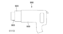
この種のコネクタは、例えば、特許文献1に開示されている。図32及び図33を参照すると、コネクタ900は、コネクタ本体910と、ケース920と、保持部材930と、係止部材940と、スライダ950とを備えている。ケース920は、矢印で示される所定方向に沿って移動可能となるようにコネクタ本体910を収容している。保持部材930は、ケース920を所定方向に移動可能となるように保持している。係止部材940は、保持部材930に対するケース920の移動をロックする。スライダ950は、コネクタ900と相手側コネクタ(図示せず)とが未嵌合の状態において、ケース920の外側に突出している。コネクタ900が相手側コネクタと嵌合すると、スライダ950は、相手側コネクタによりケース920内に押し込まれる。押し込まれたスライダ950は、係止部材940を移動させてロックを解除する。これにより、ケース920は、保持部材930に対して移動可能となる。このように、スライダ950は、嵌合検知に用いられている。
This type of connector is disclosed, for example, in Patent Document 1. Referring to FIGS. 32 and 33,
しかしながら、特許文献1のコネクタにおいては、コネクタ900が相手側コネクタに対して未嵌合の状態であっても、スライダ950が誤って押圧されて嵌合されたものと誤検知されてしまう場合がある。
However, in the connector of Patent Document 1, even if the
そこで、本発明は、嵌合の誤検知を抑制できる構造を有するコネクタを提供することを目的とする。また、本発明は、そのコネクタを備えるコネクタ組立体を提供することを目的とする。 Then, an object of this invention is to provide the connector which has a structure which can suppress the misdetection of a fitting. Another object of the present invention is to provide a connector assembly provided with the connector.
本発明は、第1のコネクタとして、
所定方向に沿って相手側コネクタと嵌合可能なコネクタであって、
前記コネクタは、2本の電源端子と、少なくとも1本の信号端子と、嵌合検知部材と、保持機構とを備えており、
前記保持機構は、基準面と、複数の絶縁保護部と、絶縁外周壁部とを有しており、
前記絶縁保護部は、前記電源端子用の2本の絶縁保護部と、前記信号端子用の少なくとも1本の絶縁保護部とを含んでおり、
前記絶縁保護部の夫々は、前記基準面から第1所定長だけ前記所定方向に突出しており、
前記絶縁外周壁部は、前記所定方向において前記基準面を越えて突出すると共に前記所定方向と直交する面内において前記絶縁保護部を囲んでおり、
前記電源端子は、前記保持機構に保持されており、且つ、前記所定方向に沿って延びており、
前記電源端子の先端は、前記電源端子用の前記絶縁保護部に夫々収容されており、
前記信号端子は、前記保持機構に保持されており、且つ、前記所定方向に沿って延びており、
前記信号端子の先端は、前記信号端子用の前記絶縁保護部に収容されており、
前記嵌合検知部材は、前記所定方向において突出位置と後退位置との間で移動可能となるように、前記保持機構に保持されており、
前記突出位置にあるとき、前記嵌合検知部材は、前記第1所定長よりも短い第2所定長だけ前記基準面から突出しており、
前記コネクタが前記相手側コネクタと嵌合すると、前記嵌合検知部材は、前記相手側コネクタに押圧されて、前記後退位置まで移動する
コネクタを提供する。
In the present invention, as the first connector,
A connector that can be mated with a mating connector along a predetermined direction, wherein
The connector includes two power terminals, at least one signal terminal, a fitting detection member, and a holding mechanism.
The holding mechanism includes a reference surface, a plurality of insulating protection portions, and an insulating outer peripheral wall portion.
The insulation protection unit includes two insulation protection units for the power supply terminal and at least one insulation protection unit for the signal terminal,
Each of the insulation protection portions protrudes in the predetermined direction by a first predetermined length from the reference surface,
The insulating outer peripheral wall portion protrudes beyond the reference surface in the predetermined direction and surrounds the insulating protection portion in a plane perpendicular to the predetermined direction.
The power supply terminal is held by the holding mechanism and extends along the predetermined direction,
The tip of the power supply terminal is accommodated in the insulating protection portion for the power supply terminal, respectively.
The signal terminal is held by the holding mechanism and extends along the predetermined direction,
The tip of the signal terminal is accommodated in the insulation protecting portion for the signal terminal,
The fitting detection member is held by the holding mechanism so as to be movable between the projecting position and the retracted position in the predetermined direction,
When in the protruding position, the fitting detection member protrudes from the reference surface by a second predetermined length shorter than the first predetermined length,
When the connector is fitted with the mating connector, the fitting detection member is pressed by the mating connector to provide a connector that moves to the retracted position.
また、本発明は、第2のコネクタとして、第1のコネクタであって、
前記所定方向と直交する面内において、前記嵌合検知部材の先端の中心は、3本の近接する前記絶縁保護部の中心を頂点とする三角形の内側に配置されている
コネクタを提供する。
The present invention also relates to a first connector as the second connector, wherein
In a plane orthogonal to the predetermined direction, the center of the tip of the fitting detection member provides a connector disposed inside a triangle whose apex is the center of three adjacent insulating protective portions.
また、本発明は、第3のコネクタとして、第1のコネクタであって、
前記信号端子は、少なくとも2本あり、
前記絶縁保護部は、前記信号端子用の少なくとも2本の絶縁保護部を含んでおり、
前記所定方向と直交する面内において、前記嵌合検知部材の先端の中心は、4本の近接する前記絶縁保護部の中心を頂点とする四角形の対角線の少なくとも一方上に配置されている
コネクタを提供する。
The present invention also relates to a first connector as the third connector, wherein
There are at least two signal terminals,
The insulation protection portion includes at least two insulation protection portions for the signal terminal,
In the plane orthogonal to the predetermined direction, the center of the tip of the fitting detection member is a connector disposed on at least one of the diagonals of a quadrangle having the centers of the four adjacent insulating protection portions as the vertices. provide.
また、本発明は、第4のコネクタとして、第1のコネクタであって、
前記所定方向と直交する面内において、前記嵌合検知部材の先端の中心は、最も外側に配置された前記絶縁保護部であって互いに近接する2本の前記絶縁保護部の中心を結ぶ線分と、前記近接する2本の前記絶縁保護部の中心から前記絶縁外周壁部まで夫々下した2つの垂線と、前記絶縁外周壁部とで囲まれる領域のうち小さい領域の内側に配置されている
コネクタを提供する。
The present invention is the first connector as the fourth connector, wherein
In the plane orthogonal to the predetermined direction, the center of the tip of the fitting detection member is the insulation protection portion disposed on the outermost side, and a line segment connecting the centers of the two insulation protection portions adjacent to each other And two perpendicular lines respectively falling from the centers of the two adjacent insulating protection portions adjacent to each other to the insulating outer peripheral wall portion, and are disposed inside a smaller region among the regions surrounded by the insulating outer peripheral wall portion. Provide a connector.
また、本発明は、第5のコネクタとして、第1乃至第4のいずれかのコネクタであって、
前記相手側コネクタは、被ロック部を有しており、
前記保持機構は、ロック部材と、前記ロック部材とは別体のロック維持部材とを備えており、
前記ロック部材は、ロック部を有すると共に、ロック位置又はアンロック位置のいずれかを取り得るものであり、
前記ロック部材が前記ロック位置にあるとき、前記ロック部が前記被ロック部にロックして前記コネクタの前記相手側コネクタに対する嵌合をロックする一方、前記ロック部材が前記アンロック位置にあるとき、前記コネクタの前記相手側コネクタからの抜去を可能とし、
前記ロック維持部材は、維持状態と許容状態を選択的に取り得るものであり、
前記ロック維持部材が前記維持状態にあるとき、前記ロック部材の前記ロック位置から前記アンロック位置への移動が制限され、
前記ロック維持部材が前記許容状態にあるとき、前記ロック部材の前記ロック位置から前記アンロック位置への移動が許容され、
前記嵌合検知部材は、前記突出位置にあるとき、前記ロック維持部材が前記維持状態をとることを禁止し、前記後退位置にあるとき、前記ロック維持部材が前記維持状態をとることを許容している
コネクタを提供する。
The present invention is any one of the first to fourth connectors as the fifth connector, wherein
The mating connector has a locked portion,
The holding mechanism includes a lock member and a lock holding member separate from the lock member.
The lock member has a lock portion and can take either a lock position or an unlock position.
When the lock member is in the lock position, the lock portion locks to the locked portion to lock the fitting of the connector with the mating connector, while the lock member is in the unlock position; Enabling removal of the connector from the mating connector,
The lock maintenance member can selectively take the maintenance state and the allowance state,
When the lock maintenance member is in the maintenance state, the movement of the lock member from the lock position to the unlock position is restricted.
When the lock maintenance member is in the allowable state, movement of the lock member from the lock position to the unlock position is permitted.
The fitting detection member prohibits the lock maintenance member from taking the maintenance state when in the projecting position, and allows the lock maintenance member to take the maintenance state when in the retracted position. Provide a connector.
また、本発明は、第6のコネクタとして、第5のコネクタであって、
前記ロック部材は、第1操作部を有しており、
前記第1操作部を第1操作方向に操作すると、前記ロック部材は前記ロック位置から前記アンロック位置に移動し、
前記ロック維持部材は、第2操作部及び被ストップ部を有しており、
前記嵌合検知部材は、ストッパ部を有しており、
前記嵌合検知部材が前記突出位置にあるとき、前記第1操作方向及び前記所定方向と交差する第2操作方向において前記ストッパ部が前記被ストップ部と少なくとも部分的に重複して前記ロック維持部材の前記第2操作方向への移動を規制しており、
前記嵌合検知部材が前記後退位置にあるとき、前記所定方向において前記ストッパ部と前記被ストップ部とがズレて位置しており、前記第2操作部を前記第2操作方向に操作すると、前記ロック維持部材は前記許容状態から前記維持状態へと遷移する
コネクタを提供する。
The present invention is a fifth connector as the sixth connector, wherein
The lock member has a first operation portion,
When the first operation unit is operated in the first operation direction, the lock member moves from the lock position to the unlock position,
The lock maintenance member has a second operation portion and a stopped portion,
The fitting detection member has a stopper portion,
When the fitting detection member is in the projecting position, the stopper portion at least partially overlaps the stopped portion in the second operation direction intersecting the first operation direction and the predetermined direction. Restricting the movement of the
When the fitting detection member is in the retracted position, the stopper portion and the stopped portion are misaligned in the predetermined direction, and the second operation portion is operated in the second operation direction. The lock retention member provides a connector that transitions from the allowed state to the maintained state.
また、本発明は、第7のコネクタとして、第6のコネクタであって、
前記保持機構は、ハウジングを更に備えており、
前記ロック維持部材は、前記第2操作方向に沿って移動可能となるように前記ハウジングに保持されたスライダである
コネクタを提供する。
The present invention is the seventh connector as the seventh connector, wherein
The holding mechanism further comprises a housing,
The lock maintenance member provides a connector which is a slider held by the housing so as to be movable along the second operation direction.
また、本発明は、第8のコネクタとして、第7のコネクタであって、
前記ロック部材は、軸部と被規制部とを更に備えており、
前記軸部は、前記ロック部と前記第1操作部との間に位置しており、
前記ロック部材は、前記軸部を中心に前記ロック部と前記第1操作部とがシーソー運動可能となるように前記ハウジングに支持されており、
前記ロック維持部材には、前記所定方向に突出した規制部が設けられており、
前記ロック維持部材が前記許容状態にあるとき、前記規制部は前記被規制部の前記第1操作方向に沿った移動を規制しない一方、前記ロック維持部材が前記維持状態にあるとき、前記規制部は前記被規制部の前記第1操作方向に沿った移動を規制する
コネクタを提供する。
The present invention is the seventh connector as the eighth connector, wherein
The lock member further includes a shaft portion and a restricted portion,
The shaft portion is located between the lock portion and the first operation portion,
The lock member is supported by the housing such that the lock portion and the first operation portion can perform a seesaw motion around the shaft portion,
The lock maintaining member is provided with a restricting portion projecting in the predetermined direction,
When the lock maintaining member is in the allowable state, the restricting portion does not restrict the movement of the restricted portion along the first operation direction, and when the lock maintaining member is in the maintaining state, the restricting portion The present invention provides a connector for restricting the movement of the restricted portion along the first operation direction.
また、本発明は、第9のコネクタとして、第8のコネクタであって、
前記被ストップ部は、前記所定方向に突出した断面L字状の突起であり、
前記嵌合検知部材は、前記所定方向に沿って延びるロッド部を有しており、
前記ストッパ部は、前記所定方向と直交する直交方向に前記ロッド部から延びている
コネクタを提供する。
The present invention is the eighth connector as the ninth connector, wherein
The said to-be-stopped part is a cross-sectional L-shaped protrusion which protruded in the said predetermined direction,
The fitting detection member has a rod portion extending along the predetermined direction,
The stopper portion provides a connector extending from the rod portion in a direction orthogonal to the predetermined direction.
また、本発明は、第10のコネクタとして、第5乃至第9のいずれかのコネクタであって、
前記保持機構は、位置検知機構と、状態検知機構とを更に備えており、
前記位置検知機構は、前記ロック部材が前記ロック位置又は前記アンロック位置のいずれに位置しているかを検知しており、
前記状態検知機構は、前記ロック維持部材が前記維持状態にあるか前記許容状態にあるかを検知している
コネクタを提供する。
The present invention is any one of the fifth to ninth connectors as the tenth connector, wherein
The holding mechanism further includes a position detection mechanism and a state detection mechanism.
The position detection mechanism detects whether the lock member is located at the lock position or the unlock position,
The state detection mechanism provides a connector that detects whether the lock maintenance member is in the maintenance state or in the allowance state.
また、本発明は、第1乃至第10のいずれかのコネクタと、相手側コネクタとを備えるコネクタ組立体であって、
前記相手側コネクタは、前記電源端子に対応する相手側電源端子と、前記信号端子に対応する相手側信号端子と、相手側保持機構とを備えており、
前記相手側保持機構は、相手側基準面と、相手側押圧部とを有しており、
前記コネクタが前記相手側コネクタと嵌合したとき、前記絶縁保護部の先端は、前記相手側基準面と対向しており、
前記相手側押圧部は、前記所定方向において前記相手側基準面から第3所定長だけ離れて位置しており、
前記第3所定長は、前記第1所定長以下であり、
前記コネクタが前記相手側コネクタと嵌合したとき、前記相手側押圧部は、前記嵌合検知部材を前記後退位置まで押し込む
コネクタ組立体を提供する。
The present invention is also a connector assembly comprising any one of the first to tenth connectors and a mating connector,
The mating connector includes a mating power terminal corresponding to the power terminal, a mating signal terminal corresponding to the signal terminal, and a mating holding mechanism.
The counterpart holding mechanism has a counterpart reference surface and a counterpart pressing portion,
When the connector is engaged with the mating connector, the tip of the insulation protection portion faces the mating reference surface,
The mating pressing portion is located away from the mating reference surface by a third predetermined length in the predetermined direction,
The third predetermined length is equal to or less than the first predetermined length,
The mating pressing portion provides a connector assembly that pushes the fitting detection member to the retracted position when the connector is mated with the mating connector.
本発明によれば、絶縁外周壁部で囲まれた領域内であって少なくとも3本の絶縁保護部が平行に延びている領域内に、突出位置にある嵌合検知部材が突出している。加えて、突出位置にある嵌合検知部材の突出長(第2所定長)は、絶縁保護部の長さ(第1所定長)よりも短い。そのため、意図しない部材や部位が嵌合検知部材に対して到達してしまうことを絶縁外周壁部や絶縁保護部により防ぐことができ、嵌合が誤検知される可能性を抑制することができる。 According to the present invention, in the area surrounded by the insulating outer peripheral wall and the area in which at least three insulation protection parts extend in parallel, the fitting detection member at the protruding position protrudes. In addition, the projection length (second predetermined length) of the fitting detection member in the projection position is shorter than the length (first predetermined length) of the insulation protection portion. Therefore, the insulation outer peripheral wall portion and the insulation protection portion can prevent an unintended member or part from reaching the fitting detection member, and the possibility of erroneous detection of fitting can be suppressed. .
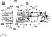
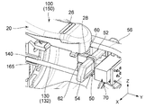
図1、図2、図21及び図23を参照すると、本発明の実施の形態によるコネクタ組立体300は、コネクタ(プラグ)100と、所定方向に沿ってコネクタ100と嵌合する相手側コネクタ(インレット)200とを備えている。本実施の形態の所定方向は、Y方向であり、前後方向としても参照される。例えば、相手側コネクタ200はEV(図示せず)に搭載された受電コネクタであり、コネクタ100は給電システム(図示せず)から延びるケーブル(図示せず)に接続される充電コネクタ又は給電コネクタである。逆に、相手側コネクタ200はEVに搭載された電源コネクタであり、コネクタ100はEVから電源供給を受けるための受電コネクタであってもよい。図6に示されるように、相手側コネクタ200には、被ロック部202及び相手側押圧部230が設けられている。相手側コネクタ200の被ロック部202及び相手側押圧部230以外の構成については、後で説明する。
Referring to FIGS. 1, 2, 21 and 23, the
図1、図2及び図9から理解されるように、本実施の形態によるコネクタ100は、2本の電源端子110と、4本の信号端子120と、嵌合検知部材130と、保持機構150とを備えている。
As understood from FIGS. 1, 2 and 9, the
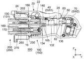
図6、図15及び図16から理解されるように、保持機構150は、絶縁体からなるハウジング10と、コイルばねからなるバイアス部材15と、ロックレバーからなるロック部材20と、位置検知機構40と、スライダからなるロック維持部材50と、状態検知機構70とを備えている。
As understood from FIGS. 6, 15 and 16, the
図1及び図2に示されるように、ハウジング10は、基準面160と、フランジ収容部165と、複数の絶縁保護部170と、絶縁外周壁部180とを有している。図9から理解されるように、複数の絶縁保護部170は、電源端子用の2本の絶縁保護部170と、信号端子用の少なくとも1本の絶縁保護部170とを含んでいる。本実施の形態において、信号端子用の絶縁保護部170の本数は、4本である。即ち、信号端子用の絶縁保護部170の本数は、信号端子120の本数と等しい。但し、本発明はこれに限定されるわけではなく、複数本の信号端子120をまとめて1本の絶縁保護部170で保護することとしてもよい。
As shown in FIGS. 1 and 2, the
図2に最もよく示されるように、絶縁保護部170の夫々は、基準面160から所定方向において第1所定長だけ突出している。本実施の形態においては、絶縁保護部170の基準面160からの突出方向を前方とする。即ち、前方は、−Y方向である。絶縁外周壁部180は、所定方向において基準面160を越えて前方に突出すると共に所定方向と直交する面内において絶縁保護部170を囲んでいる。本実施の形態において、所定方向と直交する面は、XZ平面である。本実施の形態の絶縁外周壁部180は、所定方向において、絶縁保護部170よりも大きなサイズを有している。また、すべての絶縁保護部170が絶縁外周壁部180により囲まれた領域内に位置している。図2及び図9から理解されるように、基準面160は、絶縁外周壁部180により囲まれた領域の後壁又は底部である。図1から理解されるように、本実施の形態のフランジ収容部165は、基準面160から離れて且つ基準面160よりも後方に設けられている。図4に示されるように、フランジ収容部165は、一部にキー面(平面)を有する略筒状の構造を有しており、所定方向に沿って延びている。
As best shown in FIG. 2, each of the
図1及び図2に示されるように、電源端子110は、保持機構150のハウジング10に保持されている。電源端子110は、所定方向に沿って延びている。電源端子110の一部(電源端子110の先端を含む部分)は、電源端子用の絶縁保護部170に夫々収容されている。同様に、信号端子120は、保持機構150のハウジング10に保持されている。信号端子120は、所定方向に沿って延びている。信号端子120の一部(信号端子120の先端を含む部分)は、信号端子用の絶縁保護部170に収容されている。図2に示されるように、絶縁保護部170は、先端に開口部172を有しており、その開口部172を通して電源端子110や信号端子120に接触することができる。
As shown in FIGS. 1 and 2, the
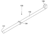
図1及び図6から理解されるように、嵌合検知部材130は、所定方向において突出位置と後退位置との間で移動可能となるように、保持機構150のハウジング10に保持されている。図1乃至図4に示される嵌合検知部材130は、突出位置に位置している。図6乃至図8並びに図21乃至図24に示される嵌合検知部材130は、後退位置に位置している。
As understood from FIGS. 1 and 6, the
図1、図5及び図6に示されるように、本実施の形態の嵌合検知部材130は、ロッド部132と、ストッパ部136とを有している。ロッド部132は、所定方向に沿って延びており、ロッド部132上にはD字状の断面を有するフランジ部134が設けられている。図4に示されるように、フランジ部134は、ロッド部132上に取り付けられたばね部140と共に、ハウジング10のフランジ収容部165に収容されている。フランジ部134は、ばね部140により前方に押圧されており、そのため、図1に示されるように、嵌合検知部材130は、初期状態において、突出位置に位置している。フランジ部134のD字状の断面は、フランジ収容部165のキー面と共に、ロッド部132の回転を防止している。図1及び図6に示されるように、ストッパ部136は、ロッド部132から、上方に延びている。本実施の形態において、上方は、+Z方向である。
As shown in FIG. 1, FIG. 5 and FIG. 6, the
図2に示されるように、本実施の形態において、嵌合検知部材130が突出位置にあるとき、嵌合検知部材130の突出長は最長である。具体的には、突出位置にあるとき、嵌合検知部材130は、第2所定長だけ基準面160から突出している。本実施の形態において、第2所定長は、第1所定長より短い。即ち、嵌合検知部材130は、突出位置にあるときでも、絶縁保護部170を越えて突出することはない。
As shown in FIG. 2, in the present embodiment, when the
図6及び図7に示されるように、コネクタ100が相手側コネクタ200と嵌合すると、嵌合検知部材130は、相手側コネクタ200の相手側押圧部230に押圧されて、後退位置まで移動する。即ち、本実施の形態のコネクタ100は、嵌合検知部材130の位置により、コネクタ100と相手側コネクタ200との嵌合を検知することができる。
As shown in FIGS. 6 and 7, when the
本実施の形態においては、嵌合検知部材130は、突出位置にあるとき、絶縁外周壁部180で囲まれた領域内であって計6本の絶縁保護部170が平行に延びている領域内に、突出している。加えて、第2所定長は、第1所定長よりも短い。即ち、突出位置にある嵌合検知部材130の突出長は、絶縁保護部170の長さよりも短い。そのため、意図しない部材や部位が嵌合検知部材130に対して到達してしまうことを絶縁外周壁部180や絶縁保護部170により防ぐことができ、嵌合が誤検知される可能性を抑制することができる。
In the present embodiment, when the
嵌合検知部材130の先端131の想定し得る具体的な配置を以下に配置1〜配置3として示す。
Specific possible arrangements of the
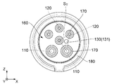
(配置1)
図1及び図2を参照して、配置1は、信号端子120を少なくとも1本備えており、それに対応する絶縁保護部170を1本備えていれば採用し得る。このケースでは、電源端子110は2本あり、それに対応する絶縁保護部170も2本あるので、絶縁保護部170は、合計で少なくとも3本ある。この前提の下、配置1においては、図9に示されるように、所定方向と直交する面内(即ち、XZ平面内)において、嵌合検知部材130の先端131の中心は、3本の近接する絶縁保護部170の中心を頂点とする三角形STの内側に配置されている。本実施の形態のコネクタ100においては、この配置1を採用している。配置1の場合、意図しない部材や部位は3本の絶縁保護部170により嵌合検知部材130まで到達することを阻まれることから、嵌合検知部材130の先端131は、3本の絶縁保護部170により実質的に保護されている。なお、コネクタ100の嵌合部の形状は、図9に示される略円形のものには限られず、例えば図10に示される角丸四角形のものであってもよい。
(Arrangement 1)
With reference to FIGS. 1 and 2, Arrangement 1 may be employed as long as it includes at least one
(配置2)
図1及び図2を参照して、配置2は、信号端子120を少なくとも2本備えており、それに対応する絶縁保護部170を2本備えている場合に採用し得る。このケースでは、電源端子110は2本あり、それに対応する絶縁保護部170も2本あるので、絶縁保護部170は、合計で少なくとも4本ある。この前提の下、配置2においては、図11又は図12に示されるように、所定方向と直交する面内において、嵌合検知部材130の先端131の中心は、4本の近接する絶縁保護部170の中心を頂点とする四角形SRの対角線の少なくとも一方上に配置されている。嵌合検知部材130の先端131の中心は、2本の対角線の交点上に配置されていてもよい。この配置2の場合、意図しない部材や部位は4本の絶縁保護部170により嵌合検知部材130まで到達することを阻まれることから、嵌合検知部材130の先端131は、4本の絶縁保護部170により実質的に保護されている。
(Arrangement 2)
With reference to FIGS. 1 and 2, Arrangement 2 can be adopted when at least two
(配置3)
図1及び図2を参照して、配置3は、絶縁外周壁部180と2本の絶縁保護部170を備えていれば成立するものである。図13又は図14を参照して、所定方向と直交する面内において最も外側に配置された絶縁保護部170であって互いに近接する2本の絶縁保護部170を選ぶ。選ばれた2本の絶縁保護部170とそれらの絶縁保護部170から最短距離のところに位置する絶縁外周壁部180の一部との間には、他の絶縁保護部170は存在していない。このような2本の絶縁保護部170の中心を結ぶ線分と、それら2本の絶縁保護部170の中心から絶縁外周壁部180まで夫々下した2つの垂線とで、絶縁外周壁部180で囲まれる領域を2つに分ける。配置3においては、図13又は図14に示されるように、それらの2つの領域のうちの小さい方の領域SSの内側に嵌合検知部材130の先端131の中心が配置されている。即ち、配置3においては、所定方向と直交する面内において、嵌合検知部材130の先端131の中心は、外側に位置する絶縁保護部170のうちの近接する2本の絶縁保護部170の中心を結ぶ線分と、近接する2本の絶縁保護部170の中心から絶縁外周壁部180まで夫々下した2つの垂線と、絶縁外周壁部180とで囲まれる領域のうち小さい領域SSの内側に配置されている。この配置3の場合、意図しない部材や部位は2本の絶縁保護部170と絶縁外周壁部180により嵌合検知部材130まで到達することを阻まれることから、嵌合検知部材130の先端131は、2本の絶縁保護部170と絶縁外周壁部180により実質的に保護されている。
(Arrangement 3)
Referring to FIGS. 1 and 2, Arrangement 3 is established if insulating outer
更に、相手側コネクタ200が以下のような構造を備えていると、嵌合検知の精度を高めることができる。詳しくは、図1及び図2に示されるように、相手側コネクタ200は、相手側電源端子210と、相手側信号端子220と、相手側保持機構250とを備えている。相手側電源端子210は、電源端子110と対応しており、相手側信号端子220は、信号端子120と対応している。即ち、図1及び図6から理解されるように、コネクタ100が相手側コネクタ200と嵌合すると、電源端子110は相手側電源端子210と接続し、信号端子120は相手側信号端子220と接続する。
Furthermore, when the
図2に最も良く示されるように、相手側保持機構250は、相手側基準面260と、相手側押圧部230と、相手側絶縁保護部270とを有している。相手側電源端子210及び相手側信号端子220は、夫々、相手側絶縁保護部270に収容されている。このことから理解されるように、相手側絶縁保護部270は、絶縁保護部170に夫々対応している。本実施の形態において、各相手側絶縁保護部270は、それに対応する相手側電源端子210や相手側信号端子220を囲むようにして保護している。図6に示されるように、コネクタ100が相手側コネクタ200と嵌合したとき、絶縁保護部170は相手側絶縁保護部270に夫々受容される。相手側絶縁保護部270の最奥端は、相手側基準面260を構成している。即ち、コネクタ100が相手側コネクタ200と嵌合したとき、絶縁保護部170の先端は、相手側基準面260と対向する。
As best shown in FIG. 2, the
図2に示されるように、相手側押圧部230は、所定方向において相手側基準面260から第3所定長だけ離れて位置している。ここで、第3所定長は、第1所定長以下である。このため、コネクタ100が相手側コネクタ200と完全に嵌合しなければ、相手側押圧部230は、嵌合検知部材130を後退位置まで押し込むことができない。図6に示されるように、コネクタ100が相手側コネクタ200と完全に嵌合すると、相手側押圧部230は、嵌合検知部材130を後退位置まで押し込むことができる。即ち、上述した構造のコネクタ100及び相手側コネクタ200を備えるコネクタ組立体300によれば、適切な嵌合が行われたか否かを検知することができる。
As shown in FIG. 2, the
図3、図4並びに図6乃至図8から理解されるように、本実施の形態においては、嵌合検知部材130による嵌合検知結果をロック維持部材50の状態制御に使用している。以下、本実施の形態の保持機構150の詳細な構造とロック維持部材50の状態制御について説明する。
As understood from FIGS. 3, 4 and 6 to 8, in the present embodiment, the fitting detection result by the
図25に示されるように、ロック部材20は、軸部22と、ロック部24と、第1操作部26と、被規制部28と、収容部30と、押圧部32とを有している。軸部22は、ロック部24と第1操作部26との間に位置している。被規制部28は、ロック部材20の一端に形成されている。収容部30と押圧部32は、軸部22と第1操作部26との間に位置している。本実施の形態において、押圧部32は、収容部30と被規制部28との間に位置している。
As shown in FIG. 25, the
図25から明らかなように、本実施の形態のロック部材20は、単一の部材からなる。即ち、ロック部24と第1操作部26とは同一部材に形成されている。そのため、第1操作部26に対する操作によりロック部24を直接操作することができる。
As apparent from FIG. 25, the
図1、図6、図15及び図16に示されるように、ロック部材20はハウジング10に支持されている。図6及び図21から理解されるように、軸部22は、横方向に延びている。本実施の形態において、横方向はX方向である。図15、図16及び図21から理解されるように、ロック部24と第1操作部26とは、軸部22を中心としてシーソー運動可能となっている。即ち、第1操作部26が−Z側に移動するときロック部24が+Z側に移動し、第1操作部26が+Z側に移動するときロック部24が−Z側に移動する。図22及び図24から理解されるように、第1操作部26、被規制部28及び押圧部32は、ロック部材20の一端近傍に設けられている。具体的には、第1操作部26は被規制部28及び押圧部32よりも+Z側に位置しており、被規制部28と押圧部32は第1操作部26よりも−Z側に位置している。即ち、第1操作部26は被規制部28及び押圧部32よりも上側に位置しており、被規制部28と押圧部32は第1操作部26よりも下側に位置している。
As shown in FIGS. 1, 6, 15 and 16, the locking
図15及び図16に示されるように、ロック部材20の収容部30には、バイアス部材(コイルばね)15が収容されている。バイアス部材15の一端はハウジング10に固定され、他端は収容部30の内壁に当てられている。これにより、収容部30はバイアス部材15から上方に向かうバネ力を受け続けている。そのため、第1操作部26を操作していないときは、ロック部24が図15に示される位置に位置している。このときのロック部材20の位置をロック位置という。一方、第1操作部26を第1操作方向に押圧操作すると、図16及び図17に示されるように、ロック部24が第1操作方向の逆方向に移動する。このときのロック部材20の位置をアンロック位置という。本実施の形態においては、第1操作方向は−Z方向、即ち下方である。
As shown in FIG. 15 and FIG. 16, a bias member (coil spring) 15 is accommodated in the
このように、ロック部材20は、ロック位置とアンロック位置とを取ることができる。ロック部材20は、通常、バイアス部材15によりロック位置に移動させられている。このロック部材20は、第1操作部26を第1操作方向に操作すると、ロック位置からアンロック位置に移動する。第1操作部26に対する操作を止めると、ロック部材20は、バイアス部材15により再びロック位置に戻る。
Thus, the locking
図6及び図15から理解されるように、ロック部材20がロック位置にあるときには、ロック部24が相手側コネクタ200の被ロック部202にロックしてコネクタ100の相手側コネクタ200に対する嵌合をロックする。一方、図16から理解されるように、ロック部材20がアンロック位置にあるときには、ロック部24と相手側コネクタ200の被ロック部202との係合が解除される。従って、ロック部材20がアンロック位置にあるとき、コネクタ100の相手側コネクタ200からの抜去が可能となる。
As understood from FIGS. 6 and 15, when the
図15及び図16から理解されるように、位置検知機構40は、ロック部材20がロック位置に位置しているかアンロック位置に位置しているかを検知するためのものである。
As understood from FIGS. 15 and 16, the
図29から理解されるように、本実施の形態による位置検知機構40は、第1スイッチSW1と第1抵抗Raとを並列接続してなる第1並列回路PC1を有している。本実施の形態の第1抵抗Raの抵抗値は220Ωである。第1抵抗Raは他の抵抗値を有していてもよい。また、第1抵抗Raに代えて、他のインピーダンス素子を採用してもよい。
As understood from FIG. 29, the
第1並列回路PC1は、第1スイッチSW1のスイッチング動作に応じてインピーダンスの変化する第1可変インピーダンスを有している。具体的には、第1可変インピーダンスは、第1スイッチSW1が閉じているとき0Ωであり、第1スイッチSW1が開いているとき220Ωである。 The first parallel circuit PC1 has a first variable impedance whose impedance changes in accordance with the switching operation of the first switch SW1. Specifically, the first variable impedance is 0Ω when the first switch SW1 is closed, and 220Ω when the first switch SW1 is open.
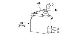
図26に示されるように、本実施の形態の第1スイッチSW1は、リミットスイッチからなるものであり、アーム42の先端を押圧されるとボタン44が押圧されるものである。第1スイッチSW1は、ノーマルクローズ型のものである。即ち、第1スイッチSW1は、通常状態においては閉じており、アーム42を介してボタン44が押圧されると開くものである。
As shown in FIG. 26, the first switch SW1 of this embodiment is a limit switch, and when the tip of the
図6、図15及び図16から理解されるように、第1スイッチSW1は、ハウジング10内に組み込まれている。第1スイッチSW1の位置はロック部材20の下側である。特に、図15及び図16に示されるように、アーム42の先端は、ロック部材20の押圧部32の下側に位置している。図15から理解されるように、ロック部材20がロック位置にあるとき、アーム42と押圧部32とは接触していない。従って、第1スイッチSW1は閉じている。一方、図16から理解されるように、ロック部材20がアンロック位置にあるとき、アーム42は押圧部32に押圧され、それによってボタン44も押圧される。そのため、第1スイッチSW1は開くこととなる。このように、第1スイッチSW1は、ロック部材20がロック位置にあるかアンロック位置にあるかに応じてスイッチ状態が変化する。なお、ロック部材20がロック位置にあるとき第1スイッチSW1が閉じているのであれば(即ち、ボタン44が押圧されないのであれば)、アーム42と押圧部32とが接触していてもよい。但し、製造バラつき及び組立バラつきを考慮すると、第1スイッチSW1のスイッチ状態を意図した通りにするためには、ロック部材20がロック位置にあるとき、アーム42と押圧部32とが接触していないことが好ましい。
As understood from FIGS. 6, 15 and 16, the first switch SW1 is incorporated in the
図27に示されるように、本実施の形態のロック維持部材50は、ロック部材20と別体であり、主部52と、主部52と直交する方向に主部52から突出した規制部60及び被ストップ部62とを有している。主部52の両端は、それぞれ第2操作部54及び第3操作部56として機能する。第2操作部54及び第3操作部56は、斜め方向に延びる端部を有している。第2操作部54及び第3操作部56の形状は後述するようにハウジング10の外形に合わせたものであり、異なる形状のハウジング10を有する場合には他の形状であってもよい。
As shown in FIG. 27, the
図3、図21及び図23に示されるように、ロック維持部材50は、ハウジング10に保持されている。図23から理解されるように、主部52は、横方向に沿って延びており、ロック維持部材50は、X方向に沿ってスライド可能である。主部52は、ロック部材20の後側に位置している。図24に示されるように、規制部60は、主部52から前方に突出している。図22、図24及び図27から理解されるように、被ストップ部62は、主部52から所定方向に突出したL字状の断面を有する突起であり、先端は、下方に向いている。
As shown in FIGS. 3, 21 and 23, the
ロック維持部材50は、第2操作部54がハウジング10から大きく突出している図18の状態と、第3操作部56がハウジング10から大きく突出している図20の状態との2つの状態を取ることができる。前者のロック維持部材50の状態を許容状態とし、後者のロック維持部材50の状態を維持状態とする。即ち、第2操作部54を第2操作方向に沿って押圧操作すると、第3操作部56がハウジング10から大きく突出し、ロック維持部材50は許容状態から維持状態に遷移する。本実施の形態において、第2操作方向は−X方向である。一方、第3操作部56を第2操作方向の逆方向に沿って押圧操作すると(即ち、第3操作部56を+X方向に押圧すると)、第2操作部54がハウジング10から大きく突出し、ロック維持部材50は維持状態から許容状態に遷移する。
The
図3及び図4に示されるように、嵌合検知部材130が突出位置にあるとき、ストッパ部136は、第2操作方向において被ストップ部62と部分的に重複し、ロック維持部材50の第2操作方向への移動を規制する。そのため、嵌合検知部材130が突出位置にあるとき、ロック維持部材50は、維持状態に遷移することができない。即ち、嵌合検知部材130は、突出位置にあるとき、ロック維持部材50が維持状態をとることを禁止している。一方、図6乃至図8に示されるように、嵌合検知部材130が後退位置にあるとき、所定方向においてストッパ部136と被ストップ部62とがズレて位置している。そのため、図6乃至図8並びに図21乃至図24から理解されるように、嵌合検知部材130が後退位置にあるとき、第2操作部54を第2操作方向に操作することができ、ロック維持部材50は許容状態から維持状態へと遷移することができる。即ち、本実施の形態の嵌合検知部材130は、後退位置にあるとき、ロック維持部材50が維持状態をとることを許容している。
As shown in FIGS. 3 and 4, when the
図7、図8及び図16を参照して、ロック部材20がロック位置にあるとき、被規制部28の下側のスペースが空いているので、ロック維持部材50を横方向にスライドさせ、規制部60を横方向に移動させてもロック部材20と規制部60とはぶつからない。即ち、ロック部材20がロック位置にあるとき、ロック維持部材50は図20の維持状態と図18の許容状態とをとることができる。
With reference to FIGS. 7, 8 and 16, when the
図24に示されるように、ロック維持部材50が維持状態にあるとき、規制部60はロック部材20の被規制部28の下側に位置している。そのため、ロック部材20の第1操作部26を操作してロック部材20をアンロック位置に移動させようとしても被規制部28が規制部60にぶつかってアンロック位置には移動できない。即ち、ロック維持部材50が維持状態にあるとき、規制部60がロック部材20の被規制部28の移動を規制しており、ロック部材20のロック位置からアンロック位置への移動が制限され、図6に示されるコネクタ100の相手側コネクタ200に対する嵌合がロックされる。
As shown in FIG. 24, when the
図3及び図8に示されるようにロック維持部材50が許容状態にあるとき、規制部60はロック部材20の被規制部28の下側には位置していない。そのため、規制部60はロック部材20の移動を規制しておらず、従って、ロック部材20は図19のロック位置と図17のアンロック位置とを自由にとることが出来る。即ち、ロック維持部材50が許容状態にあるとき、ロック部材20はロック位置とアンロック位置との間で自由に移動することができる。
When the
なお、図8に示されるようにロック部材20がアンロック位置にあるとき、規制部60は、ロック部材20の+X側に位置している。そのため、ロック維持部材50を−X方向にスライドさせようとしても規制部60がロック部材20にぶつかって移動できない。即ち、ロック部材20がアンロック位置にあるとき、ロック維持部材50は維持状態に移行することはできない。
When the
図27から理解されるように、状態検知機構70は、ロック維持部材50と組み合わせられており、ロック維持部材50が維持状態にあるか許容状態にあるかを検知するためのものである。
As understood from FIG. 27, the
図29から理解されるように、本実施の形態による状態検知機構70は、第2スイッチSW2と第2抵抗Rbとを並列接続してなる第2並列回路PC2を有している。本実施の形態の第2抵抗Rbの抵抗値は330Ωである。第2抵抗Rbは、他の抵抗値を有していてもよい。第2抵抗Rbに代えて、他のインピーダンス素子を採用してもよい。但し、本実施の形態による回路構成では、状態検知機構70の検知結果と位置検知機構40の検知結果とを区別できるように、第2抵抗Rbは、第1抵抗Raとは異なる抵抗値を有している必要がある。
As understood from FIG. 29, the
第2並列回路PC2は、第2スイッチSW2のスイッチング動作に応じてインピーダンスの変化する第2可変インピーダンスを有している。具体的には、第2可変インピーダンスは、第2スイッチSW2が閉じているとき0Ωであり、第2スイッチSW2が開いているとき330Ωである。 The second parallel circuit PC2 has a second variable impedance whose impedance changes in accordance with the switching operation of the second switch SW2. Specifically, the second variable impedance is 0Ω when the second switch SW2 is closed, and is 330Ω when the second switch SW2 is open.
図28に示されるように、本実施の形態の第2スイッチSW2は、スライドスイッチであり、つまみ72をスライドさせることでスイッチング状態を変更するものである。
As shown in FIG. 28, the second switch SW2 of the present embodiment is a slide switch, and the switching state is changed by sliding the
図4並びに図6乃至図8に示されるように、第2スイッチSW2はハウジング10内に組み込まれており、ロック維持部材50の後側に位置している。詳しくは、図24、図27及び図28を参照すると、第2スイッチSW2のつまみ72がロック維持部材50に保持されており、ロック維持部材50のスライド動作により第2スイッチSW2をスイッチングすることができる。図20乃至図22から理解されるように、具体的には、ロック維持部材50が維持状態にあるとき、即ち、第3操作部56がハウジング10から大きく突出しているとき、第2スイッチSW2は閉じている。ロック維持部材50が許容状態にあるとき、即ち、第2操作部54がハウジング10から大きく突出しているとき、第2スイッチSW2は開いている。
As shown in FIGS. 4 and 6 to 8, the second switch SW 2 is incorporated in the
図29に示されるように、本実施の形態において、位置検知機構40と状態検知機構70とは互いに接続されて、単一の出力部82を有する単一の総合検知機構80を構成している。具体的には、本実施の形態の総合検知機構80は、第1並列回路PC1と第2並列回路PC2と第3抵抗Rcを直列に接続してなる回路を有している。これにより、総合検知機構80は、第1可変インピーダンスと第2可変インピーダンスと第3抵抗Rcの抵抗値(インピーダンス)とを合成してなる合成可変インピーダンスを有している。
As shown in FIG. 29, in the present embodiment,
図29及び図30から理解されるように、合成可変インピーダンスは、位置検知機構40における検知結果と状態検知機構70における検知結果の組み合わせに応じて4通りのインピーダンスを有している。このインピーダンスの変化は、総合検知機構80の出力部82から出力される信号に現れる。即ち、出力部82から出力される信号には、位置検知機構40における検知結果と状態検知機構70における検知結果とが重畳されている。
As understood from FIGS. 29 and 30, the combined variable impedance has four impedances in accordance with the combination of the detection result of the
具体的には、図21、図22及び図29を参照して、第1スイッチSW1が閉じており且つ第2スイッチSW2が閉じているとき、ロック部材20はロック位置に位置しており且つロック維持部材50は維持状態にある。このときのロック部材20の位置とロック維持部材50の状態の組み合わせを組み合わせC1とする。コネクタ100と相手側コネクタ200とが嵌合しているときに、この組み合わせC1が成立している場合、電力の授受を行うことができる。
Specifically, referring to FIGS. 21, 22, and 29, when the first switch SW1 is closed and the second switch SW2 is closed, the
図16、図22及び図29を参照して、第1スイッチSW1が開いており且つ第2スイッチSW2が閉じているとき、ロック部材20がアンロック位置に位置しており且つロック維持部材50が維持状態にあることを意味している。このときのロック部材20の位置とロック維持部材50の状態の組み合わせを組み合わせC2とする。コネクタ100の各構成要素が適切な動きをしているときには、この組み合わせC2は成立しない。即ち、組み合わせC2が成立している場合、構成要素同士がかんでしまっている可能性が高いことが理解できる。
Referring to FIGS. 16, 22 and 29, when the first switch SW1 is open and the second switch SW2 is closed, the
図8、図24及び図29を参照して、第1スイッチSW1が閉じており且つ第2スイッチSW2が開いているとき、ロック部材20がロック位置に位置しており且つロック維持部材50が許容状態にあることを意味している。このときのロック部材20の位置とロック維持部材50の状態の組み合わせを組み合わせC3とする。この組み合わせC3が成立している場合、意図的であるか、意図していないかに関わらず、ロック維持部材50は許容状態にある。例えば、ロック維持部材50を維持状態にしたつもりでも、第2操作部54をきちんと操作しきれておらず、規制部60が被規制部28の移動を規制できない状態となっているのかもしれない。この場合、第1操作部26は自由に操作可能となっており、簡単にロックが外れて、コネクタ100が相手側コネクタ200から抜け落ちてしまう可能性がある。
Referring to FIGS. 8, 24 and 29, when the first switch SW1 is closed and the second switch SW2 is open, the
図3、図17及び図29を参照して、第1スイッチSW1が開いており且つ第2スイッチSW2が開いているとき、ロック部材20がアンロック位置に位置しており且つロック維持部材50が許容状態にあることを意味している。このときのロック部材20の位置とロック維持部材50の組み合わせを組み合わせC4とする。この組み合わせC4が成立しているとき、即ち、ロック部材20の第1操作部26を操作してロックを外そうとしていることが理解される。
Referring to FIGS. 3, 17 and 29, when the first switch SW1 is open and the second switch SW2 is open, the
このように、本実施の形態においては、ロック部材20の位置やロック維持部材50の状態を細かく把握することができる。
Thus, in the present embodiment, the position of the
本実施の形態によるコネクタ100を採用するシステム(例えば、給電システム)においては、位置検知機構40における検知結果と状態検知機構70における検知結果の組み合わせに応じて4通りの検知結果を表示することができる。
In a system (for example, a power feeding system) adopting
本実施の形態のコネクタ100によれば、ロック部材20の移動を規制するロック維持部材50を手動で操作するものとしたことから、ソレノイドを備えるコネクタと比較して、安価且つ小型化することができ、且つ、ロック維持部材50の状態の切り替えを確実に行うことができる。
According to the
加えて、位置検知機構40と状態検知機構70の2つの検知機構を設けたことから、例えば、給電しようとしても給電できないときに、ロック部24が被ロック部202にロックしていないから給電できないのか、ロック維持部材50によりロックが維持されていないから給電できないのかを特定することができる。
In addition, since the
更に、嵌合検知部材130により、未嵌合の状態においてロック維持部材50が維持状態をとることが禁止されている。未嵌合の状態においてロック部材20がロック位置に固定されてしまっていると、コネクタ100を相手側コネクタ200と嵌合する際に、ロック部材20が破損してしまう可能性がある。本実施の形態によれば、未嵌合の状態においてロック部材20がロック位置に固定されることがなくなることから、上述した破損を避けることができる。
Further, the
以上、本発明について実施の形態を掲げて具体的に説明してきたが、本発明はこれに限定されるわけではなく、様々な応用や変形が可能である。 As mentioned above, although the embodiment of the present invention has been specifically described, the present invention is not limited to this, and various applications and modifications are possible.
例えば、上述したロック部材20は、ハウジング10の外部に露出していたが、第1操作部26がハウジング10の外部から操作可能であれば、ロック部材20の大部分をハウジング10内に収容することとしてもよい。
For example, although the
また、上述した第1スイッチSW1はノーマルクローズ型であったが、第1スイッチSW1はノーマルオープン型であってもよい。また、第1スイッチSW1は、リミットスイッチであったが、他のタイプのスイッチであってもよい。同様に、第2スイッチSW2は、スライドスイッチであったが、他のタイプのスイッチであってもよい。 Further, although the above-described first switch SW1 is a normally closed type, the first switch SW1 may be a normally open type. Further, although the first switch SW1 is a limit switch, it may be another type of switch. Similarly, the second switch SW2 is a slide switch, but may be another type of switch.
更に、上述した実施の形態において、位置検知機構40及び状態検知機構70は、夫々、第1並列回路PC1及び第2並列回路PC2からなるものであったが、位置検知機構40を直列回路で構成してもよいし、状態検知機構70を直列回路で構成してもよい。
Furthermore, in the above-described embodiment, the
例えば、図31に示されるように、位置検知機構40は第1スイッチSW1と第1抵抗Raを直列接続してなる第1直列回路SC1を有しており、状態検知機構70は第2スイッチSW2と第2抵抗Rbを直列接続してなる第2直列回路SC1を有していてもよい。更に、総合検知機構80は、第1直列回路SC1と第2直列回路SC2と第3抵抗Rcとを並列に接続して構成してもよい。この場合も、位置検知機構40における検知結果と状態検知機構70における検知結果とが重畳された信号を出力部82から出力することができる。
For example, as shown in FIG. 31, the
上述した実施の形態においては、コネクタ100は4本の信号端子120を備えていたが、本発明は、これに限定されるわけではない。コネクタ100は、少なくとも1本の信号端子120を備えており、その信号端子120と2つの電源端子110に対応する計3本の絶縁保護部170を備えているのであれば、信号端子120の本数は問わない。
Although the
また、上述した実施の形態においては、コネクタ100が相手側コネクタ200と嵌合したとき、絶縁保護部170が相手側絶縁保護部270に受容されていたが、本発明は、これに限定されるわけではない。逆に、相手側絶縁保護部270が絶縁保護部170に受容されるようにコネクタ100と相手側コネクタ200の構成を変更してもよい。
Further, in the above-described embodiment, when the
10 ハウジング
15 バイアス部材(コイルばね)
20 ロック部材
22 軸部
24 ロック部
26 第1操作部
28 被規制部
30 収容部
32 押圧部
40 位置検知機構
42 アーム
44 ボタン
PC1 第1並列回路
SC1 第1直列回路
SW1 第1スイッチ
Ra 第1抵抗
50 ロック維持部材
52 主部
54 第2操作部
56 第3操作部
60 規制部
62 被ストップ部
70 状態検知機構
72 つまみ
PC2 第2並列回路
SC2 第2直列回路
SW2 第2スイッチ
Rb 第2抵抗
80 総合検知機構
82 出力部
Rc 第3抵抗
100 コネクタ(プラグ)
110 電源端子
120 信号端子
130 嵌合検知部材
131 先端
132 ロッド部
134 フランジ部
136 ストッパ部
140 ばね部
150 保持機構
160 基準面
165 フランジ収容部
170 絶縁保護部
172 開口部
180 絶縁外周壁部
ST 三角形
SR 四角形
SS 領域
200 相手側コネクタ(インレット)
202 被ロック部
210 相手側電源端子
220 相手側信号端子
230 相手側押圧部
250 相手側保持機構
260 相手側基準面
270 相手側絶縁保護部
300 コネクタ組立体
10
DESCRIPTION OF
202
Claims (11)
前記コネクタは、2本の電源端子と、少なくとも1本の信号端子と、嵌合検知部材と、保持機構とを備えており、
前記保持機構は、基準面と、複数の絶縁保護部と、絶縁外周壁部とを有しており、
前記絶縁保護部は、前記電源端子用の2本の絶縁保護部と、前記信号端子用の少なくとも1本の絶縁保護部とを含んでおり、
前記絶縁保護部の夫々は、前記基準面から第1所定長だけ前記所定方向に突出しており、
前記絶縁外周壁部は、前記所定方向において前記基準面を越えて突出すると共に前記所定方向と直交する面内において前記絶縁保護部を囲んでおり、
前記電源端子は、前記保持機構に保持されており、且つ、前記所定方向に沿って延びており、
前記電源端子の先端は、前記電源端子用の前記絶縁保護部に夫々収容されており、
前記信号端子は、前記保持機構に保持されており、且つ、前記所定方向に沿って延びており、
前記信号端子の先端は、前記信号端子用の前記絶縁保護部に収容されており、
前記嵌合検知部材は、前記所定方向において突出位置と後退位置との間で移動可能となるように、前記保持機構に保持されており、
前記突出位置にあるとき、前記嵌合検知部材は、前記第1所定長よりも短い第2所定長だけ前記基準面から突出しており、
前記コネクタが前記相手側コネクタと嵌合すると、前記嵌合検知部材は、前記相手側コネクタに押圧されて、前記後退位置まで移動し、
前記相手側コネクタは、被ロック部を有しており、
前記保持機構は、ロック部材と、前記ロック部材とは別体のロック維持部材とを備えており、
前記ロック部材は、ロック部を有すると共に、ロック位置又はアンロック位置のいずれかを取り得るものであり、
前記ロック部材が前記ロック位置にあるとき、前記ロック部が前記被ロック部にロックして前記コネクタの前記相手側コネクタに対する嵌合をロックする一方、前記ロック部材が前記アンロック位置にあるとき、前記コネクタの前記相手側コネクタからの抜去を可能とし、
前記ロック維持部材は、維持状態と許容状態を選択的に取り得るものであり、
前記ロック維持部材が前記維持状態にあるとき、前記ロック部材の前記ロック位置から前記アンロック位置への移動が制限され、
前記ロック維持部材が前記許容状態にあるとき、前記ロック部材の前記ロック位置から前記アンロック位置への移動が許容され、
前記嵌合検知部材は、前記突出位置にあるとき、前記ロック維持部材が前記維持状態をとることを禁止し、前記後退位置にあるとき、前記ロック維持部材が前記維持状態をとることを許容している
コネクタ。 A connector that can be mated with a mating connector along a predetermined direction, wherein
The connector includes two power terminals, at least one signal terminal, a fitting detection member, and a holding mechanism.
The holding mechanism includes a reference surface, a plurality of insulating protection portions, and an insulating outer peripheral wall portion.
The insulation protection unit includes two insulation protection units for the power supply terminal and at least one insulation protection unit for the signal terminal,
Each of the insulation protection portions protrudes in the predetermined direction by a first predetermined length from the reference surface,
The insulating outer peripheral wall portion protrudes beyond the reference surface in the predetermined direction and surrounds the insulating protection portion in a plane perpendicular to the predetermined direction.
The power supply terminal is held by the holding mechanism and extends along the predetermined direction,
The tip of the power supply terminal is accommodated in the insulating protection portion for the power supply terminal, respectively.
The signal terminal is held by the holding mechanism and extends along the predetermined direction,
The tip of the signal terminal is accommodated in the insulation protecting portion for the signal terminal,
The fitting detection member is held by the holding mechanism so as to be movable between the projecting position and the retracted position in the predetermined direction,
When in the protruding position, the fitting detection member protrudes from the reference surface by a second predetermined length shorter than the first predetermined length,
When the connector is fitted to the mating connector, the fitting detection member is pressed by the mating connector and moves to the retracted position .
The mating connector has a locked portion,
The holding mechanism includes a lock member and a lock holding member separate from the lock member.
The lock member has a lock portion and can take either a lock position or an unlock position.
When the lock member is in the lock position, the lock portion locks to the locked portion to lock the fitting of the connector with the mating connector, while the lock member is in the unlock position; Enabling removal of the connector from the mating connector,
The lock maintenance member can selectively take the maintenance state and the allowance state,
When the lock maintenance member is in the maintenance state, the movement of the lock member from the lock position to the unlock position is restricted.
When the lock maintenance member is in the allowable state, movement of the lock member from the lock position to the unlock position is permitted.
The fitting detection member prohibits the lock maintenance member from taking the maintenance state when in the projecting position, and allows the lock maintenance member to take the maintenance state when in the retracted position. and are <br/> connector.
前記コネクタは、2本の電源端子と、少なくとも1本の信号端子と、嵌合検知部材と、保持機構とを備えており、
前記保持機構は、基準面と、複数の絶縁保護部と、絶縁外周壁部とを有しており、
前記絶縁保護部は、前記電源端子用の2本の絶縁保護部と、前記信号端子用の少なくとも1本の絶縁保護部とを含んでおり、
前記絶縁保護部の夫々は、前記基準面から第1所定長だけ前記所定方向に突出しており、
前記絶縁外周壁部は、前記所定方向において前記基準面を越えて突出すると共に前記所定方向と直交する面内において前記絶縁保護部を囲んでおり、
前記電源端子は、前記保持機構に保持されており、且つ、前記所定方向に沿って延びており、
前記電源端子の先端は、前記電源端子用の前記絶縁保護部に夫々収容されており、
前記信号端子は、前記保持機構に保持されており、且つ、前記所定方向に沿って延びており、
前記信号端子の先端は、前記信号端子用の前記絶縁保護部に収容されており、
前記嵌合検知部材は、前記所定方向において突出位置と後退位置との間で移動可能となるように、前記保持機構に保持されており、
前記突出位置にあるとき、前記嵌合検知部材は、前記第1所定長よりも短い第2所定長だけ前記基準面から突出しており、
前記コネクタが前記相手側コネクタと嵌合すると、前記嵌合検知部材は、前記相手側コネクタに押圧されて、前記後退位置まで移動し、
前記所定方向と直交する面内において、前記嵌合検知部材の先端の中心は、3本の近接する前記絶縁保護部の中心を頂点とする三角形の内側に配置されている
コネクタ。 A connector that can be mated with a mating connector along a predetermined direction, wherein
The connector includes two power terminals, at least one signal terminal, a fitting detection member, and a holding mechanism.
The holding mechanism includes a reference surface, a plurality of insulating protection portions, and an insulating outer peripheral wall portion.
The insulation protection unit includes two insulation protection units for the power supply terminal and at least one insulation protection unit for the signal terminal,
Each of the insulation protection portions protrudes in the predetermined direction by a first predetermined length from the reference surface,
The insulating outer peripheral wall portion protrudes beyond the reference surface in the predetermined direction and surrounds the insulating protection portion in a plane perpendicular to the predetermined direction.
The power supply terminal is held by the holding mechanism and extends along the predetermined direction,
The tip of the power supply terminal is accommodated in the insulating protection portion for the power supply terminal, respectively.
The signal terminal is held by the holding mechanism and extends along the predetermined direction,
The tip of the signal terminal is accommodated in the insulation protecting portion for the signal terminal,
The fitting detection member is held by the holding mechanism so as to be movable between the projecting position and the retracted position in the predetermined direction,
When in the protruding position, the fitting detection member protrudes from the reference surface by a second predetermined length shorter than the first predetermined length,
When the connector is fitted to the mating connector, the fitting detection member is pressed by the mating connector and moves to the retracted position.
In the plane orthogonal to the predetermined direction, the center of the tip of the fitting detection member is arranged inside a triangle whose apex is the center of three adjacent insulating protective portions.
前記コネクタは、2本の電源端子と、少なくとも1本の信号端子と、嵌合検知部材と、保持機構とを備えており、
前記保持機構は、基準面と、複数の絶縁保護部と、絶縁外周壁部とを有しており、
前記絶縁保護部は、前記電源端子用の2本の絶縁保護部と、前記信号端子用の少なくとも1本の絶縁保護部とを含んでおり、
前記絶縁保護部の夫々は、前記基準面から第1所定長だけ前記所定方向に突出しており、
前記絶縁外周壁部は、前記所定方向において前記基準面を越えて突出すると共に前記所定方向と直交する面内において前記絶縁保護部を囲んでおり、
前記電源端子は、前記保持機構に保持されており、且つ、前記所定方向に沿って延びており、
前記電源端子の先端は、前記電源端子用の前記絶縁保護部に夫々収容されており、
前記信号端子は、前記保持機構に保持されており、且つ、前記所定方向に沿って延びており、
前記信号端子の先端は、前記信号端子用の前記絶縁保護部に収容されており、
前記嵌合検知部材は、前記所定方向において突出位置と後退位置との間で移動可能となるように、前記保持機構に保持されており、
前記突出位置にあるとき、前記嵌合検知部材は、前記第1所定長よりも短い第2所定長だけ前記基準面から突出しており、
前記コネクタが前記相手側コネクタと嵌合すると、前記嵌合検知部材は、前記相手側コネクタに押圧されて、前記後退位置まで移動し、
前記信号端子は、少なくとも2本あり、
前記絶縁保護部は、前記信号端子用の少なくとも2本の絶縁保護部を含んでおり、
前記所定方向と直交する面内において、前記嵌合検知部材の先端の中心は、4本の近接する前記絶縁保護部の中心を頂点とする四角形の対角線の少なくとも一方上に配置されている
コネクタ。 A connector that can be mated with a mating connector along a predetermined direction, wherein
The connector includes two power terminals, at least one signal terminal, a fitting detection member, and a holding mechanism.
The holding mechanism includes a reference surface, a plurality of insulating protection portions, and an insulating outer peripheral wall portion.
The insulation protection unit includes two insulation protection units for the power supply terminal and at least one insulation protection unit for the signal terminal,
Each of the insulation protection portions protrudes in the predetermined direction by a first predetermined length from the reference surface,
The insulating outer peripheral wall portion protrudes beyond the reference surface in the predetermined direction and surrounds the insulating protection portion in a plane perpendicular to the predetermined direction.
The power supply terminal is held by the holding mechanism and extends along the predetermined direction,
The tip of the power supply terminal is accommodated in the insulating protection portion for the power supply terminal, respectively.
The signal terminal is held by the holding mechanism and extends along the predetermined direction,
The tip of the signal terminal is accommodated in the insulation protecting portion for the signal terminal,
The fitting detection member is held by the holding mechanism so as to be movable between the projecting position and the retracted position in the predetermined direction,
When in the protruding position, the fitting detection member protrudes from the reference surface by a second predetermined length shorter than the first predetermined length,
When the connector is fitted to the mating connector, the fitting detection member is pressed by the mating connector and moves to the retracted position.
There are at least two signal terminals,
The insulation protection portion includes at least two insulation protection portions for the signal terminal,
In the plane orthogonal to the predetermined direction, the center of the tip of the fitting detection member is disposed on at least one of the diagonals of a quadrangle having the centers of the four adjacent insulating protective portions as apexes.
前記所定方向と直交する面内において、前記嵌合検知部材の先端の中心は、最も外側に配置された前記絶縁保護部であって互いに近接する2本の前記絶縁保護部の中心を結ぶ線分と、前記近接する2本の前記絶縁保護部の中心から前記絶縁外周壁部まで夫々下した2つの垂線と、前記絶縁外周壁部とで囲まれる領域のうち小さい領域の内側に配置されている
コネクタ。 The connector according to claim 1, wherein
In the plane orthogonal to the predetermined direction, the center of the tip of the fitting detection member is the insulation protection portion disposed on the outermost side, and a line segment connecting the centers of the two insulation protection portions adjacent to each other And two perpendicular lines respectively falling from the centers of the two adjacent insulating protection portions adjacent to each other to the insulating outer peripheral wall portion, and are disposed inside a smaller region among the regions surrounded by the insulating outer peripheral wall portion. connector.
前記相手側コネクタは、被ロック部を有しており、
前記保持機構は、ロック部材と、前記ロック部材とは別体のロック維持部材とを備えており、
前記ロック部材は、ロック部を有すると共に、ロック位置又はアンロック位置のいずれかを取り得るものであり、
前記ロック部材が前記ロック位置にあるとき、前記ロック部が前記被ロック部にロックして前記コネクタの前記相手側コネクタに対する嵌合をロックする一方、前記ロック部材が前記アンロック位置にあるとき、前記コネクタの前記相手側コネクタからの抜去を可能とし、
前記ロック維持部材は、維持状態と許容状態を選択的に取り得るものであり、
前記ロック維持部材が前記維持状態にあるとき、前記ロック部材の前記ロック位置から前記アンロック位置への移動が制限され、
前記ロック維持部材が前記許容状態にあるとき、前記ロック部材の前記ロック位置から前記アンロック位置への移動が許容され、
前記嵌合検知部材は、前記突出位置にあるとき、前記ロック維持部材が前記維持状態をとることを禁止し、前記後退位置にあるとき、前記ロック維持部材が前記維持状態をとることを許容している
コネクタ。 The connector according to claim 2 or claim 3 , wherein
The mating connector has a locked portion,
The holding mechanism includes a lock member and a lock holding member separate from the lock member.
The lock member has a lock portion and can take either a lock position or an unlock position.
When the lock member is in the lock position, the lock portion locks to the locked portion to lock the fitting of the connector with the mating connector, while the lock member is in the unlock position; Enabling removal of the connector from the mating connector,
The lock maintenance member can selectively take the maintenance state and the allowance state,
When the lock maintenance member is in the maintenance state, the movement of the lock member from the lock position to the unlock position is restricted.
When the lock maintenance member is in the allowable state, movement of the lock member from the lock position to the unlock position is permitted.
The fitting detection member prohibits the lock maintenance member from taking the maintenance state when in the projecting position, and allows the lock maintenance member to take the maintenance state when in the retracted position. Connector.
前記ロック部材は、第1操作部を有しており、
前記第1操作部を第1操作方向に操作すると、前記ロック部材は前記ロック位置から前記アンロック位置に移動し、
前記ロック維持部材は、第2操作部及び被ストップ部を有しており、
前記嵌合検知部材は、ストッパ部を有しており、
前記嵌合検知部材が前記突出位置にあるとき、前記第1操作方向及び前記所定方向と交差する第2操作方向において前記ストッパ部が前記被ストップ部と少なくとも部分的に重複して前記ロック維持部材の前記第2操作方向への移動を規制しており、
前記嵌合検知部材が前記後退位置にあるとき、前記所定方向において前記ストッパ部と前記被ストップ部とがズレて位置しており、前記第2操作部を前記第2操作方向に操作すると、前記ロック維持部材は前記許容状態から前記維持状態へと遷移する
コネクタ。 The connector according to claim 1, 4 or 5 , wherein
The lock member has a first operation portion,
When the first operation unit is operated in the first operation direction, the lock member moves from the lock position to the unlock position,
The lock maintenance member has a second operation portion and a stopped portion,
The fitting detection member has a stopper portion,
When the fitting detection member is in the projecting position, the stopper portion at least partially overlaps the stopped portion in the second operation direction intersecting the first operation direction and the predetermined direction. Restricting the movement of the
When the fitting detection member is in the retracted position, the stopper portion and the stopped portion are misaligned in the predetermined direction, and the second operation portion is operated in the second operation direction. A connector in which a lock maintenance member transitions from the allowed state to the maintained state.
前記保持機構は、ハウジングを更に備えており、
前記ロック維持部材は、前記第2操作方向に沿って移動可能となるように前記ハウジングに保持されたスライダである
コネクタ。 The connector according to claim 6, wherein
The holding mechanism further comprises a housing,
The connector, wherein the lock maintaining member is a slider held by the housing so as to be movable along the second operation direction.
前記ロック部材は、軸部と被規制部とを更に備えており、
前記軸部は、前記ロック部と前記第1操作部との間に位置しており、
前記ロック部材は、前記軸部を中心に前記ロック部と前記第1操作部とがシーソー運動可能となるように前記ハウジングに支持されており、
前記ロック維持部材には、前記所定方向に突出した規制部が設けられており、
前記ロック維持部材が前記許容状態にあるとき、前記規制部は前記被規制部の前記第1操作方向に沿った移動を規制しない一方、前記ロック維持部材が前記維持状態にあるとき、前記規制部は前記被規制部の前記第1操作方向に沿った移動を規制する
コネクタ。 The connector according to claim 7, wherein
The lock member further includes a shaft portion and a restricted portion,
The shaft portion is located between the lock portion and the first operation portion,
The lock member is supported by the housing such that the lock portion and the first operation portion can perform a seesaw motion around the shaft portion,
The lock maintaining member is provided with a restricting portion projecting in the predetermined direction,
When the lock maintaining member is in the allowable state, the restricting portion does not restrict the movement of the restricted portion along the first operation direction, and when the lock maintaining member is in the maintaining state, the restricting portion A connector that restricts movement of the restricted portion along the first operation direction.
前記被ストップ部は、前記所定方向に突出した断面L字状の突起であり、
前記嵌合検知部材は、前記所定方向に沿って延びるロッド部を有しており、
前記ストッパ部は、前記所定方向と直交する直交方向に前記ロッド部から延びている
コネクタ。 The connector according to claim 8, wherein
The said to-be-stopped part is a cross-sectional L-shaped protrusion which protruded in the said predetermined direction,
The fitting detection member has a rod portion extending along the predetermined direction,
The connector extends from the rod portion in a direction perpendicular to the predetermined direction.
前記保持機構は、位置検知機構と、状態検知機構とを更に備えており、
前記位置検知機構は、前記ロック部材が前記ロック位置又は前記アンロック位置のいずれに位置しているかを検知しており、
前記状態検知機構は、前記ロック維持部材が前記維持状態にあるか前記許容状態にあるかを検知している
コネクタ。 A connector according to any one of claims 1, 4 and 5 to 9, wherein
The holding mechanism further includes a position detection mechanism and a state detection mechanism.
The position detection mechanism detects whether the lock member is located at the lock position or the unlock position,
The connector according to claim 1, wherein the state detection mechanism detects whether the lock maintenance member is in the maintenance state or in the allowance state.
前記相手側コネクタは、前記電源端子に対応する相手側電源端子と、前記信号端子に対応する相手側信号端子と、相手側保持機構とを備えており、
前記相手側保持機構は、相手側基準面と、相手側押圧部とを有しており、
前記コネクタが前記相手側コネクタと嵌合したとき、前記絶縁保護部の先端は、前記相手側基準面と対向しており、
前記相手側押圧部は、前記所定方向において前記相手側基準面から第3所定長だけ離れて位置しており、
前記第3所定長は、前記第1所定長以下であり、
前記コネクタが前記相手側コネクタと嵌合したとき、前記相手側押圧部は、前記嵌合検知部材を前記後退位置まで押し込む
コネクタ組立体。 A connector assembly comprising the connector according to any one of claims 1 to 10 and a mating connector,
The mating connector includes a mating power terminal corresponding to the power terminal, a mating signal terminal corresponding to the signal terminal, and a mating holding mechanism.
The counterpart holding mechanism has a counterpart reference surface and a counterpart pressing portion,
When the connector is engaged with the mating connector, the tip of the insulation protection portion faces the mating reference surface,
The mating pressing portion is located away from the mating reference surface by a third predetermined length in the predetermined direction,
The third predetermined length is equal to or less than the first predetermined length,
The connector assembly in which the mating pressing unit pushes the fitting detection member to the retracted position when the connector is fitted to the mating connector.
Priority Applications (3)
| Application Number | Priority Date | Filing Date | Title |
|---|---|---|---|
| JP2015173221A JP6537938B2 (en) | 2015-09-02 | 2015-09-02 | Connector and connector assembly |
| US15/202,290 US9711904B2 (en) | 2015-09-02 | 2016-07-05 | Connector and connector assembly |
| EP16180744.1A EP3139452B1 (en) | 2015-09-02 | 2016-07-22 | Connector and connector assembly |
Applications Claiming Priority (1)
| Application Number | Priority Date | Filing Date | Title |
|---|---|---|---|
| JP2015173221A JP6537938B2 (en) | 2015-09-02 | 2015-09-02 | Connector and connector assembly |
Publications (3)
| Publication Number | Publication Date |
|---|---|
| JP2017050179A JP2017050179A (en) | 2017-03-09 |
| JP2017050179A5 JP2017050179A5 (en) | 2018-07-05 |
| JP6537938B2 true JP6537938B2 (en) | 2019-07-03 |
Family
ID=56507516
Family Applications (1)
| Application Number | Title | Priority Date | Filing Date |
|---|---|---|---|
| JP2015173221A Expired - Fee Related JP6537938B2 (en) | 2015-09-02 | 2015-09-02 | Connector and connector assembly |
Country Status (3)
| Country | Link |
|---|---|
| US (1) | US9711904B2 (en) |
| EP (1) | EP3139452B1 (en) |
| JP (1) | JP6537938B2 (en) |
Families Citing this family (8)
| Publication number | Priority date | Publication date | Assignee | Title |
|---|---|---|---|---|
| JP6811654B2 (en) * | 2017-03-14 | 2021-01-13 | 日立オートモティブシステムズ株式会社 | connector |
| DK3453559T3 (en) | 2017-09-12 | 2020-07-13 | Dietmar Niederl | Charging cable and adapter for electrically charging an energy storage device on an energy supply device |
| CN108790901B (en) * | 2018-06-20 | 2022-01-21 | 安徽恒泰机械股份有限公司 | New energy automobile rifle head locking device that charges |
| CN110834558B (en) * | 2019-11-19 | 2021-03-23 | 安徽天鹏电子科技有限公司 | New forms of energy fill electric pile's controlling means |
| US11139616B2 (en) | 2020-02-17 | 2021-10-05 | Japan Aviation Electronics Industry, Limited | Charging connector |
| CN114142305B (en) * | 2021-08-24 | 2023-05-12 | 深圳市德兰明海科技有限公司 | Connector and electronic equipment |
| TWI784701B (en) | 2021-09-03 | 2022-11-21 | 太康精密股份有限公司 | Electrical connectors for power and signal transmission |
| CN114006223A (en) * | 2021-10-28 | 2022-02-01 | 深圳市泰格莱精密电子有限公司 | Novel charging connector and electric automobile |
Family Cites Families (31)
| Publication number | Priority date | Publication date | Assignee | Title |
|---|---|---|---|---|
| US5065282A (en) * | 1986-10-17 | 1991-11-12 | Polonio John D | Interconnection mechanisms for electronic components |
| JPH04133375U (en) | 1991-05-30 | 1992-12-11 | 日本航空電子工業株式会社 | Switch integrated connector |
| JP2856231B2 (en) | 1992-05-13 | 1999-02-10 | 株式会社タツノ・メカトロニクス | Charging device |
| US5413493A (en) * | 1993-01-15 | 1995-05-09 | Hubbell Incorporated | Electrical connector assembly, especially for electric vehicle |
| JPH0765891A (en) * | 1993-08-20 | 1995-03-10 | Sumitomo Wiring Syst Ltd | Charge connector for electric vehicle |
| JP2904024B2 (en) * | 1994-08-08 | 1999-06-14 | 住友電装株式会社 | Electric vehicle charging connector |
| US5676560A (en) * | 1994-12-01 | 1997-10-14 | Yazaki Corporation | Powder feed connector |
| JPH09120866A (en) | 1995-10-26 | 1997-05-06 | Yazaki Corp | Connector provided with terminal insertion detection fixture and terminal insertion detection mechanism |
| JP3449517B2 (en) * | 1996-10-04 | 2003-09-22 | 矢崎総業株式会社 | Electric vehicle charging connector |
| US6053756A (en) * | 1998-05-04 | 2000-04-25 | Applied Materials, Inc. | Interlock safety device |
| JP3817118B2 (en) * | 1999-09-20 | 2006-08-30 | 矢崎総業株式会社 | Half-mating prevention connector |
| US7404720B1 (en) * | 2007-03-29 | 2008-07-29 | Tesla Motors, Inc. | Electro mechanical connector for use in electrical applications |
| JP2009252656A (en) | 2008-04-10 | 2009-10-29 | Univ Nihon | Plug and tap |
| CN102917904B (en) * | 2010-03-31 | 2016-07-06 | 凯毅德股份公司 | Actuator and locking device for motor vehicles |
| JP5249284B2 (en) * | 2010-05-12 | 2013-07-31 | 株式会社東海理化電機製作所 | Lock manual release structure of power plug lock device |
| US8075329B1 (en) * | 2010-06-08 | 2011-12-13 | Ford Global Technologies, Llc | Method and system for preventing disengagement between an electrical plug and a charge port on an electric vehicle |
| JP5632690B2 (en) | 2010-09-17 | 2014-11-26 | 株式会社東海理化電機製作所 | Power plug lock device |
| CN102005680A (en) * | 2010-12-10 | 2011-04-06 | 怡达电气(苏州)有限公司 | Charging connector for electric vehicle |
| JP5080662B2 (en) | 2011-01-27 | 2012-11-21 | 日本航空電子工業株式会社 | connector |
| JP5503619B2 (en) | 2011-10-25 | 2014-05-28 | 古河電気工業株式会社 | Power supply connector |
| JP5917918B2 (en) * | 2012-01-16 | 2016-05-18 | 日産自動車株式会社 | Power supply connector |
| JP5916476B2 (en) | 2012-03-29 | 2016-05-11 | 古河電気工業株式会社 | Power supply connector |
| JP5718302B2 (en) | 2012-11-19 | 2015-05-13 | 古河電気工業株式会社 | Power supply connector |
| JP2014150012A (en) | 2013-02-04 | 2014-08-21 | Furukawa Electric Co Ltd:The | Connector |
| EP2862242B1 (en) * | 2013-03-15 | 2019-03-06 | Sabritec | Connector system with connection sensor |
| WO2014147764A1 (en) * | 2013-03-19 | 2014-09-25 | 住友電装株式会社 | Vehicle-side connector |
| JP2014182912A (en) | 2013-03-19 | 2014-09-29 | Dainippon Printing Co Ltd | Attachment plug coming-off detection device |
| JP2015072851A (en) | 2013-10-04 | 2015-04-16 | 古河電気工業株式会社 | Connector |
| JP6148964B2 (en) * | 2013-10-17 | 2017-06-14 | 日本航空電子工業株式会社 | connector |
| JP2015082340A (en) * | 2013-10-21 | 2015-04-27 | 矢崎総業株式会社 | Charge connector |
| US9763661B2 (en) * | 2014-06-26 | 2017-09-19 | Covidien Lp | Adapter assembly for interconnecting electromechanical surgical devices and surgical loading units, and surgical systems thereof |
-
2015
- 2015-09-02 JP JP2015173221A patent/JP6537938B2/en not_active Expired - Fee Related
-
2016
- 2016-07-05 US US15/202,290 patent/US9711904B2/en active Active
- 2016-07-22 EP EP16180744.1A patent/EP3139452B1/en not_active Not-in-force
Also Published As
| Publication number | Publication date |
|---|---|
| US9711904B2 (en) | 2017-07-18 |
| EP3139452B1 (en) | 2018-06-20 |
| EP3139452A1 (en) | 2017-03-08 |
| JP2017050179A (en) | 2017-03-09 |
| US20170062986A1 (en) | 2017-03-02 |
Similar Documents
| Publication | Publication Date | Title |
|---|---|---|
| JP6537938B2 (en) | Connector and connector assembly | |
| JP6148964B2 (en) | connector | |
| JP5890091B2 (en) | Electric connector, electric connector unit, and charger for electric vehicle | |
| US8968021B1 (en) | Self-rejecting automotive harness connector | |
| JP5872824B2 (en) | Power circuit breaker | |
| US9716341B2 (en) | Lever-type connector assembly | |
| JP4267935B2 (en) | Electrical connector assembly and electrical connector | |
| EP2840664B1 (en) | Connector assembly with spring operated secondary lock | |
| JP6940128B6 (en) | Connector assembly with double auxiliary lock | |
| CN111033915B (en) | Locking device for plug connection | |
| US20150133002A1 (en) | Terminal position assurance with dual primary lock reinforcement and independent secondary lock | |
| JP5366759B2 (en) | connector | |
| JP6580629B2 (en) | Service plug | |
| JP2019505070A (en) | Connector system with connector position guarantee | |
| JP6377425B2 (en) | Power circuit breaker | |
| JP6133125B2 (en) | connector | |
| US6428341B2 (en) | Inspecting jig for wire harness | |
| JP5970596B2 (en) | Electric connector, electric connector unit, and charger for electric vehicle | |
| CN111525339B (en) | Lever-type connector | |
| JP2005267970A (en) | Connector | |
| JP5845368B2 (en) | Electric connector, electric connector unit, and charger for electric vehicle | |
| CN115298905A (en) | Safety power socket | |
| KR20180075678A (en) | Plug connector with locking element | |
| JP2019175559A (en) | Charging extension cable for electric vehicle | |
| JP5503611B2 (en) | Electric circuit breaker for vehicle |
Legal Events
| Date | Code | Title | Description |
|---|---|---|---|
| A521 | Request for written amendment filed |
Free format text: JAPANESE INTERMEDIATE CODE: A523 Effective date: 20180522 |
|
| A621 | Written request for application examination |
Free format text: JAPANESE INTERMEDIATE CODE: A621 Effective date: 20180522 |
|
| A977 | Report on retrieval |
Free format text: JAPANESE INTERMEDIATE CODE: A971007 Effective date: 20190221 |
|
| A131 | Notification of reasons for refusal |
Free format text: JAPANESE INTERMEDIATE CODE: A131 Effective date: 20190306 |
|
| A521 | Request for written amendment filed |
Free format text: JAPANESE INTERMEDIATE CODE: A523 Effective date: 20190404 |
|
| TRDD | Decision of grant or rejection written | ||
| A01 | Written decision to grant a patent or to grant a registration (utility model) |
Free format text: JAPANESE INTERMEDIATE CODE: A01 Effective date: 20190529 |
|
| A61 | First payment of annual fees (during grant procedure) |
Free format text: JAPANESE INTERMEDIATE CODE: A61 Effective date: 20190605 |
|
| R150 | Certificate of patent or registration of utility model |
Ref document number: 6537938 Country of ref document: JP Free format text: JAPANESE INTERMEDIATE CODE: R150 |
|
| LAPS | Cancellation because of no payment of annual fees |