WO2012099250A1 - ガスミスト吸入器 - Google Patents
ガスミスト吸入器 Download PDFInfo
- Publication number
- WO2012099250A1 WO2012099250A1 PCT/JP2012/051247 JP2012051247W WO2012099250A1 WO 2012099250 A1 WO2012099250 A1 WO 2012099250A1 JP 2012051247 W JP2012051247 W JP 2012051247W WO 2012099250 A1 WO2012099250 A1 WO 2012099250A1
- Authority
- WO
- WIPO (PCT)
- Prior art keywords
- gas
- gas mist
- mist
- liquid
- nozzle
- Prior art date
Links
Images
Classifications
-
- A—HUMAN NECESSITIES
- A61—MEDICAL OR VETERINARY SCIENCE; HYGIENE
- A61M—DEVICES FOR INTRODUCING MEDIA INTO, OR ONTO, THE BODY; DEVICES FOR TRANSDUCING BODY MEDIA OR FOR TAKING MEDIA FROM THE BODY; DEVICES FOR PRODUCING OR ENDING SLEEP OR STUPOR
- A61M16/00—Devices for influencing the respiratory system of patients by gas treatment, e.g. mouth-to-mouth respiration; Tracheal tubes
- A61M16/10—Preparation of respiratory gases or vapours
- A61M16/14—Preparation of respiratory gases or vapours by mixing different fluids, one of them being in a liquid phase
-
- A—HUMAN NECESSITIES
- A61—MEDICAL OR VETERINARY SCIENCE; HYGIENE
- A61M—DEVICES FOR INTRODUCING MEDIA INTO, OR ONTO, THE BODY; DEVICES FOR TRANSDUCING BODY MEDIA OR FOR TAKING MEDIA FROM THE BODY; DEVICES FOR PRODUCING OR ENDING SLEEP OR STUPOR
- A61M15/00—Inhalators
-
- A—HUMAN NECESSITIES
- A61—MEDICAL OR VETERINARY SCIENCE; HYGIENE
- A61H—PHYSICAL THERAPY APPARATUS, e.g. DEVICES FOR LOCATING OR STIMULATING REFLEX POINTS IN THE BODY; ARTIFICIAL RESPIRATION; MASSAGE; BATHING DEVICES FOR SPECIAL THERAPEUTIC OR HYGIENIC PURPOSES OR SPECIFIC PARTS OF THE BODY
- A61H33/00—Bathing devices for special therapeutic or hygienic purposes
- A61H33/02—Bathing devices for use with gas-containing liquid, or liquid in which gas is led or generated, e.g. carbon dioxide baths
-
- A—HUMAN NECESSITIES
- A61—MEDICAL OR VETERINARY SCIENCE; HYGIENE
- A61H—PHYSICAL THERAPY APPARATUS, e.g. DEVICES FOR LOCATING OR STIMULATING REFLEX POINTS IN THE BODY; ARTIFICIAL RESPIRATION; MASSAGE; BATHING DEVICES FOR SPECIAL THERAPEUTIC OR HYGIENIC PURPOSES OR SPECIFIC PARTS OF THE BODY
- A61H33/00—Bathing devices for special therapeutic or hygienic purposes
- A61H33/14—Devices for gas baths with ozone, hydrogen, or the like
-
- A—HUMAN NECESSITIES
- A61—MEDICAL OR VETERINARY SCIENCE; HYGIENE
- A61M—DEVICES FOR INTRODUCING MEDIA INTO, OR ONTO, THE BODY; DEVICES FOR TRANSDUCING BODY MEDIA OR FOR TAKING MEDIA FROM THE BODY; DEVICES FOR PRODUCING OR ENDING SLEEP OR STUPOR
- A61M11/00—Sprayers or atomisers specially adapted for therapeutic purposes
- A61M11/06—Sprayers or atomisers specially adapted for therapeutic purposes of the injector type
-
- A—HUMAN NECESSITIES
- A61—MEDICAL OR VETERINARY SCIENCE; HYGIENE
- A61M—DEVICES FOR INTRODUCING MEDIA INTO, OR ONTO, THE BODY; DEVICES FOR TRANSDUCING BODY MEDIA OR FOR TAKING MEDIA FROM THE BODY; DEVICES FOR PRODUCING OR ENDING SLEEP OR STUPOR
- A61M16/00—Devices for influencing the respiratory system of patients by gas treatment, e.g. mouth-to-mouth respiration; Tracheal tubes
- A61M16/10—Preparation of respiratory gases or vapours
- A61M16/12—Preparation of respiratory gases or vapours by mixing different gases
-
- A—HUMAN NECESSITIES
- A61—MEDICAL OR VETERINARY SCIENCE; HYGIENE
- A61M—DEVICES FOR INTRODUCING MEDIA INTO, OR ONTO, THE BODY; DEVICES FOR TRANSDUCING BODY MEDIA OR FOR TAKING MEDIA FROM THE BODY; DEVICES FOR PRODUCING OR ENDING SLEEP OR STUPOR
- A61M16/00—Devices for influencing the respiratory system of patients by gas treatment, e.g. mouth-to-mouth respiration; Tracheal tubes
- A61M16/0045—Means for re-breathing exhaled gases, e.g. for hyperventilation treatment
-
- A—HUMAN NECESSITIES
- A61—MEDICAL OR VETERINARY SCIENCE; HYGIENE
- A61M—DEVICES FOR INTRODUCING MEDIA INTO, OR ONTO, THE BODY; DEVICES FOR TRANSDUCING BODY MEDIA OR FOR TAKING MEDIA FROM THE BODY; DEVICES FOR PRODUCING OR ENDING SLEEP OR STUPOR
- A61M16/00—Devices for influencing the respiratory system of patients by gas treatment, e.g. mouth-to-mouth respiration; Tracheal tubes
- A61M16/06—Respiratory or anaesthetic masks
- A61M16/0666—Nasal cannulas or tubing
-
- A—HUMAN NECESSITIES
- A61—MEDICAL OR VETERINARY SCIENCE; HYGIENE
- A61M—DEVICES FOR INTRODUCING MEDIA INTO, OR ONTO, THE BODY; DEVICES FOR TRANSDUCING BODY MEDIA OR FOR TAKING MEDIA FROM THE BODY; DEVICES FOR PRODUCING OR ENDING SLEEP OR STUPOR
- A61M16/00—Devices for influencing the respiratory system of patients by gas treatment, e.g. mouth-to-mouth respiration; Tracheal tubes
- A61M16/08—Bellows; Connecting tubes ; Water traps; Patient circuits
- A61M16/0875—Connecting tubes
-
- A—HUMAN NECESSITIES
- A61—MEDICAL OR VETERINARY SCIENCE; HYGIENE
- A61M—DEVICES FOR INTRODUCING MEDIA INTO, OR ONTO, THE BODY; DEVICES FOR TRANSDUCING BODY MEDIA OR FOR TAKING MEDIA FROM THE BODY; DEVICES FOR PRODUCING OR ENDING SLEEP OR STUPOR
- A61M16/00—Devices for influencing the respiratory system of patients by gas treatment, e.g. mouth-to-mouth respiration; Tracheal tubes
- A61M16/20—Valves specially adapted to medical respiratory devices
- A61M16/208—Non-controlled one-way valves, e.g. exhalation, check, pop-off non-rebreathing valves
-
- A—HUMAN NECESSITIES
- A61—MEDICAL OR VETERINARY SCIENCE; HYGIENE
- A61M—DEVICES FOR INTRODUCING MEDIA INTO, OR ONTO, THE BODY; DEVICES FOR TRANSDUCING BODY MEDIA OR FOR TAKING MEDIA FROM THE BODY; DEVICES FOR PRODUCING OR ENDING SLEEP OR STUPOR
- A61M2202/00—Special media to be introduced, removed or treated
- A61M2202/02—Gases
- A61M2202/0208—Oxygen
-
- A—HUMAN NECESSITIES
- A61—MEDICAL OR VETERINARY SCIENCE; HYGIENE
- A61M—DEVICES FOR INTRODUCING MEDIA INTO, OR ONTO, THE BODY; DEVICES FOR TRANSDUCING BODY MEDIA OR FOR TAKING MEDIA FROM THE BODY; DEVICES FOR PRODUCING OR ENDING SLEEP OR STUPOR
- A61M2202/00—Special media to be introduced, removed or treated
- A61M2202/02—Gases
- A61M2202/0225—Carbon oxides, e.g. Carbon dioxide
-
- A—HUMAN NECESSITIES
- A61—MEDICAL OR VETERINARY SCIENCE; HYGIENE
- A61M—DEVICES FOR INTRODUCING MEDIA INTO, OR ONTO, THE BODY; DEVICES FOR TRANSDUCING BODY MEDIA OR FOR TAKING MEDIA FROM THE BODY; DEVICES FOR PRODUCING OR ENDING SLEEP OR STUPOR
- A61M2205/00—General characteristics of the apparatus
- A61M2205/82—Internal energy supply devices
- A61M2205/8218—Gas operated
- A61M2205/8225—Gas operated using incorporated gas cartridges for the driving gas
-
- A—HUMAN NECESSITIES
- A61—MEDICAL OR VETERINARY SCIENCE; HYGIENE
- A61M—DEVICES FOR INTRODUCING MEDIA INTO, OR ONTO, THE BODY; DEVICES FOR TRANSDUCING BODY MEDIA OR FOR TAKING MEDIA FROM THE BODY; DEVICES FOR PRODUCING OR ENDING SLEEP OR STUPOR
- A61M2206/00—Characteristics of a physical parameter; associated device therefor
- A61M2206/10—Flow characteristics
- A61M2206/14—Static flow deviators in tubes disturbing laminar flow in tubes, e.g. archimedes screws
Definitions
- the present invention relates to a gas mist inhaler for orally inhaling a gas mist obtained by pulverizing and dissolving a liquid such as oxygen, carbon dioxide gas, or a mixed gas of oxygen and carbon dioxide and a drug.
- carbon dioxide carbon dioxide: CO 2
- CO 2 carbon dioxide
- water soluble water soluble
- oil soluble fat soluble
- This blood circulation promoting action exerts various physiological effects such as lowering blood pressure, improving metabolism, and promoting the elimination of pain substances and waste products. It also has anti-inflammatory and antibacterial effects. Therefore, in recent years, carbon dioxide gas has attracted widespread attention not only for medical purposes but also for health promotion and beauty promotion.
- Carbon dioxide gas in living tissue has the function of releasing oxygen transported by binding to hemoglobin in red blood cells.
- red blood cells release more oxygen.
- the supply of oxygen to cells by red blood cells is mainly controlled by carbon dioxide.
- hemoglobin remains in a state where oxygen is bound, and cells cannot receive oxygen.
- carbon dioxide tends to look like a waste product resulting from cell activity, but it actually plays a very important role in the body.
- oxygen is effective in metabolic activity, blood circulation promotion, fatigue recovery, blood pressure stability, and the like.
- oxygen also has a bactericidal and sterilizing effect due to oxidation.
- nasal vaccine for developing mucosal immunity against influenza virus
- This nasal vaccine is generally more effective in preventing the onset of influenza than a vaccine injected subcutaneously, and has the advantage of being effective against various virus strains, unlike the injection type.
- antiviral agents that are administered by inhalation have also been developed for the prevention and treatment of influenza.
- the present inventor has developed a gas mist inhaler that efficiently dissolves carbon dioxide gas or oxygen in the above-described drug and effectively exerts the physiological action of the gas on the living body in addition to the drug.
- an object of the present invention is to provide a gas mist inhaler capable of maintaining hygiene and reducing costs by disposing only a part of the gas mist generator.
- the present invention provides a gas supply means for supplying oxygen, carbon dioxide gas, or a mixed gas of oxygen and carbon dioxide (hereinafter referred to as “gas”), and a connecting portion between the gas supply means, A liquid storage section for storing liquid, a nozzle to which the gas is supplied, a liquid suction pipe for supplying the liquid to the tip of the nozzle, and a liquid blown up by a gas flow from the nozzle to collide with the liquid A collision member that makes a mist obtained by pulverizing and dissolving a liquid and the gas (hereinafter referred to as “gas mist”), a cylindrical gas introduction portion that is supplied with the gas and guides the gas to the upper portion of the nozzle, and collects the gas mist A gas mist generating unit having a donut-shaped gas mist discharging unit, and an intake port connected to the gas mist generating unit and having an inlet for inhaling the gas mist into a living body.
- gas mist a gas mist generating unit having a do
- pulverizing and dissolving is a process in which a liquid is pulverized into fine droplets and brought into contact with gas (oxygen, carbon dioxide, or a mixed gas of oxygen and carbon dioxide).
- gas oxygen, carbon dioxide, or a mixed gas of oxygen and carbon dioxide.
- the gas mist generating means includes a vent for taking in outside air.
- the suction member may further have an opening for taking in outside air.
- the gas supply means is preferably a cartridge type gas cylinder. Furthermore, it is preferable that the gas supply means includes one or more of a gas supply time setting unit, a gas supply pressure adjusting unit, and a gas mixture ratio setting unit.
- the gas mist generating means may supply gas mist to a plurality of the suction members.
- the liquid is optimally one or a combination of any one of water, ionic water, ozone water, physiological saline, purified water, or sterilized purified water.
- the liquid is menthol, vitamin E, vitamin C derivative, retinol, anesthetic, cyclodextrin, photocatalyst, photocatalyst and apatite complex, hyaluronic acid, coenzyme Q10, seed oil, propolis, ethanol, chlorhexidine gluconate, amphoteric Surfactant, benzalkonium chloride, alkyldiaminoetherglycine acetate, sodium hypochlorite, peracetic acid, sodium sesquicarbonate, silica, popidone iodine, sodium bicarbonate, high-concentration carbonated spring agent, antiallergic agent, anti-inflammatory agent, antipyretic It is preferable to further contain any one or more of an analgesic agent, an antifungal agent, an anti-influ
- the particle diameter of the mist supplied from the gas mist generating means into the suction member is preferably 10 ⁇ m or less.
- the gas mist generating means has a gas mist supply pipe for supplying the gas mist into the suction member, and the gas mist supply pipe includes a filter for removing droplets adhering to the pipe. Is good. Furthermore, it is preferable that all or a part of the gas mist supply pipe is constituted by a bellows-like pipe.
- the gas mist supply pipe may be provided with a check valve.
- the removable part of the gas mist generating means is sterilized in advance.
- the gas mist inhaler of the present invention it becomes possible to consider hygiene and reduce costs by making a part of the gas mist generator replaceable (disposable). With this simple structure, not only can the medicinal solution permeate the upper and lower respiratory tracts through the physiological action of gas mist, but it can also increase the blood flow in the affected area, quickly relieve inflammation, and increase immunity. be able to.
- FIG. 1 is an overall schematic view of a gas mist inhaler according to a first embodiment of the present invention. It is a cross-sectional schematic diagram which shows the structure of the gas mist generator in the gas mist inhaler of FIG. It is a partially broken perspective view of the generator main body in the gas mist inhaler of FIG. It is a schematic diagram which shows the aspect which seals a generator main body in the gas mist inhaler of FIG. It is a perspective view of the state which looked at the cover part in the gas mist inhaler of FIG. 1 from the bottom. It is a partial expanded sectional view of the generator main body in the gas mist inhaler of FIG.
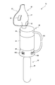
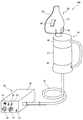
- FIG. 1 is an overall schematic view of a gas mist inhaler according to a first embodiment of the present invention.
- a gas mist inhaler 10 of this embodiment includes a gas cylinder 31 as a gas supply means 30 for supplying oxygen, carbon dioxide gas, or a mixed gas of oxygen and carbon dioxide (hereinafter simply referred to as gas), It has a gas mist generator 40 as gas mist generating means, and a suction mask 51 as a suction member 50.
- the gas cylinder 31 for supplying oxygen, carbon dioxide, or a mixed gas of oxygen and carbon dioxide to the gas mist generator 40 As the gas cylinder 31 for supplying oxygen, carbon dioxide, or a mixed gas of oxygen and carbon dioxide to the gas mist generator 40, a small cartridge type is used in this embodiment, paying attention to portability. As shown in FIG. 1, the small gas cylinder 31 is attached to the gas supply means connecting portion 45 of the gas mist generator 40 and supplies gas to the gas mist generator 40 at a predetermined pressure.
- the gas mist generator 40 stores liquid therein, generates a gas mist obtained by pulverizing and dissolving the liquid and gas by a high-speed flow of gas supplied from the gas cylinder 31, and supplies the gas mist to the suction mask 51.
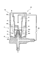
- FIG. 2 is a schematic cross-sectional view showing the structure of the gas mist generator 40.
- the gas mist generator 40 includes a generator body 41, a gas supply means connection part 45, and a lid part 46.
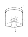
- FIG. 3 is a partially broken perspective view of the generator body 41.
- the generator main body 41 includes a liquid storage part 42 that stores liquid, a nozzle 43 that discharges a gas supplied from the gas cylinder 31 from the tip opening 43 ⁇ / b> A, and a liquid stored in the liquid storage part 42. And a liquid absorption pipe forming member 44 that constitutes a liquid absorption pipe 44 ⁇ / b> A that sucks the liquid up to the tip of the nozzle 43.
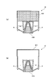
- FIG. 4 is a schematic view showing an aspect in which the generator main body 41 is sealed.
- FIG. 4A shows an example in which the upper and lower portions of the generator main body 41 are sealed with plugs 41A and 41B made of an elastic member such as rubber.
- FIG. 4B the upper part of the generator body 41 is covered with a film 41C made of aluminum, plastic or the like using heat or an adhesive, and the lower part is sealed with a stopper 41B made of an elastic member such as rubber.
- a film 41C made of aluminum, plastic or the like using heat or an adhesive
- a stopper 41B made of an elastic member such as rubber.
- the liquid reservoir 42 can be removed and replaced with another liquid reservoir 42, thereby reducing the number of disposable parts and reducing the cost.
- the generator main body 41 is sealed and provided, and it can keep hygiene by making it disposable each time. Accordingly, it is possible to omit a configuration for supplying a liquid such as a medicine to the liquid storage unit 42, and it is possible to realize a compact size and a low cost.
- liquid stored in the liquid storage section 42 it is preferable to use water, ionic water, ozone water, physiological saline, purified water, or sterilized purified water.
- these liquids may contain a drug effective for a user's disease, symptom, and the like.
- the drug include antiallergic agents, anti-inflammatory agents, antipyretic analgesics, antifungal agents, anti-influenza virus agents, influenza vaccines, steroid agents, anticancer agents, antihypertensive agents and the like.
- menthol has a refreshing action, vitamin E that promotes blood circulation, vitamin C derivative that is easily absorbed by skin tissue and has a high beautifying effect, retinol that normalizes the keratinization of the skin and protects the mucosa, and relieves irritation to the mucosa Anesthetic for removing odor, cyclodextrin for removing odors, photocatalyst with bactericidal or anti-inflammatory effect, or a composite of photocatalyst and apatite, hyaluronic acid with excellent water retention and moisturizing effect on skin, activating cells and immunity Coenzyme Q10 to improve, seed oil containing antioxidant substances and a large amount of nutrients, antioxidants, antibacterials, anti-inflammatorys, analgesics / anesthetics, immunity and other propolis, etc., alone or in combination, It is also possible to produce a synergistic effect with the physiological action of the gas.
- ethanol chlorhexidine gluconate, amphoteric surfactant, benzalkonium chloride, alkyldiaminoetherglycine acetate, sodium hypochlorite, peracetic acid, sodium sesquicarbonate, silica, popidone iodine, sodium bicarbonate may be added.
- you may add the high concentration carbonate spring agent (as an example of an active ingredient, a sulfate, carbonate, an organic acid, sodium dichloroisocyanurate) which has a carbonate and an organic acid as a main component.
- a nozzle 43 is provided in the center of the bottom of the generator main body 41 (liquid storage part 42).
- the nozzle 43 protrudes from the bottom of the liquid storage portion 42 and is formed in a substantially conical cylinder shape that is squeezed toward the upper portion of the generator body 41.
- a gas discharge port 45 ⁇ / b> A of the gas supply means connecting portion 45 is connected to the base end of the nozzle 43, and gas can be discharged from the tip opening 43 ⁇ / b> A of the nozzle 43.
- the liquid absorption pipe 44 ⁇ / b> A is formed between the outer peripheral surface of the nozzle 43 and the substantially conical cylindrical liquid absorption pipe forming member 44 that is slightly larger than the nozzle 43. That is, as shown in FIG. 2, by arranging the nozzle 43 so as to cover the liquid absorbing pipe forming member 44, the liquid absorbing pipe is provided between the outer peripheral surface of the nozzle 43 and the inner peripheral surface of the liquid absorbing pipe forming member 44. 44A is formed.
- the base end of the liquid absorption pipe forming member 44 (substantially lower part of the conical cylindrical part) is provided with a minute claw-like protrusion, so that the base end of the liquid absorption pipe formation member 44 and the liquid reservoir are stored.
- a gap is formed in the bottom surface of the part 42, and the liquid stored in the liquid storage part 42 is sucked up by the liquid absorption pipe 44A from this gap.
- the tip end portion 44B of the liquid suction pipe forming member 44 is opened in the vicinity of the tip opening 43A of the nozzle 43 so that the liquid sucked by the liquid suction pipe 44A hits the gas flow discharged from the nozzle 43. It is configured.
- the gas supply means connecting portion 45 is preferably a connecting portion to which the gas cylinder 31 can be attached with one touch.
- the gas supply means connecting portion 45 includes a regulator therein so that the flow rate of the gas supplied from the gas cylinder 31 can be adjusted.
- the gas flow supplied from the gas cylinder 31 is branched into two in the gas supply means connection part 45 (a branch part 45B in FIG. 2), one is supplied to the nozzle 43 and the other is supplied to a gas introduction part 47 described later. Is done.
- a dial switch 451 and a fuel gauge 452 are provided in the gas supply means connecting portion 45 is shown (see FIG. 1). By turning the dial switch 451, the gas supply can be turned on / off and the supply amount can be adjusted.
- the remaining amount gauge 452 displays the remaining amount of gas in the gas cylinder 31.
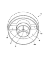
- the lid portion 46 is a member that is attached to the top of the generator body 41 and guides the generated gas mist to the suction mask 51. Further, it is a member for raising the supply pressure of the gas mist to the suction mask 51 by supplying gas into the generator body 41 separately from the nozzle 43. Details of the lid 46 are shown in FIG. FIG. 5 is a perspective view of the lid portion 46 as viewed from the bottom side.
- the lid portion 46 introduces gas into the generator main body 41 and creates a gas flow for discharging the gas mist, and a baffle (collision member) disposed at a position facing the tip opening 43A of the nozzle 43. 48 and a gas mist discharge part 49 for collecting and discharging the gas mist to the suction mask 51.
- a baffle collision member
- the gas introduction part 47 is a substantially L-shaped tubular hole that guides the gas from the outside of the lid part 46 to the periphery of the nozzle 43 of the generator main body 41, and the gas branched by the gas supply means connection part 45 is generated from the generator. It is supplied into the main body 41.
- a gas introduction port 47A connected to the gas supply means connection part 45 with a tube or the like is provided at the upper end of the gas introduction part 47.
- the gas inlet 47A may be provided with a vent for taking in outside air.
- the tube etc. which connect the gas supply means connection part 45 and the gas introduction port 47A have a flow rate adjustment part (for example, a valve) 45C for adjusting the gas supply amount to the gas introduction part 47 as shown in FIG. May be arranged.
- the baffle 48 is arranged in the vicinity of the lower end of the gas introduction part 47 by the baffle support part 48A.
- the baffle 48 may be arranged on the generator body 41 side.
- the gas mist discharge part 49 is a donut-shaped space formed around the cylindrical gas introduction part 47 by the inner side and upper part of the lid part 46.
- the gas introduction part 47 is desirably a cylindrical shape
- the gas mist discharge part 49 is desirably a donut shape, but is not necessarily limited thereto.
- the gas mist generated by the nozzle 43 and the baffle 48 is driven to the gas mist discharge part 49 by the gas from the gas introduction part 47.
- the gas mist discharge unit 49 guides the gas mist to the suction mask 51.
- a gas mist discharge port 49 ⁇ / b> A connected to the suction mask 51 is provided at the upper part of the gas mist discharge portion 49.
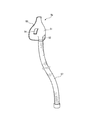
- the inhalation mask 51 is an inhalation member having a shape that covers a user's respiratory organ (here, nose and mouth) so that the user can easily inhale the generated gas mist.
- the suction mask 51 is connected to the gas mist discharge portion 49 by a connection portion 52, and the user sucks the gas mist from the suction port 53. Note that it is preferable to provide the suction mask 51 with an opening 54.
- the sealed generator main body 41 is opened, the gas supply means connecting portion 45 and the lid portion 46 are set, and the gas mist generator 40 is completed.
- the gas cylinder 31 is set in the gas supply means connecting portion 45.
- the dial switch 451 of the gas supply means connection unit 45 is turned ON, the gas starts to be supplied to the nozzle 43 and the gas introduction unit 47.
- the dial switch 451 can adjust the gas flow rate.
- the gas When the gas is supplied to the nozzle 43, since the nozzle 43 is narrowed toward the tip as shown in FIG. 6, the gas is discharged at an increased flow rate.
- the liquid is sucked up by the suction pipe 44A by the negative pressure generated by the air flow at this time, blown up by the gas at the tip 44B of the suction pipe 44A and collides with the baffle 48, and mist is generated.
- the particle size of the mist generated by this collision is desirably fine, and specifically, it is optimal to be 10 ⁇ m or less. Mist thus finely pulverized can exhibit the effect of negative ions.
- the gas is further supplied from the gas introduction unit 47 into the generator main body 41 to increase the discharge pressure of the generated gas mist.
- the gas mist is discharged from the gas mist discharge portion 49 to the suction mask 51.
- the gas mist discharged to the suction mask 51 can be sucked from the suction port 53.
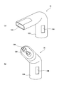
- FIG. 7 shows another example of the suction member 50.
- FIG. 7A shows a mouthpiece-type mouth mask 55 used when inhaling only from the mouth.
- the connection part 52A is connected to the gas mist discharge part 49, and the user sucks the gas mist through the inlet 53A.
- the mouth mask 55 is provided with an opening 54A.
- the mouth mask 55 is particularly suitable for treating and treating a throat symptom.
- FIG. 7B shows a nosepiece type nasal mask 56 used when inhaling only from the nose.
- the connection unit 52B is connected to the gas mist discharge unit 49, and the user inhales the gas mist through the nose through the suction port 53B.
- the nasal mask 56 is provided with an opening 54B. This nasal mask 56 is particularly suitable for treating and treating nasal symptoms such as allergic rhinitis.
- the gas mist discharge part 49 and the connection part 52 of the suction member 50 are directly connected.
- the gas mist supply pipe 57 connects the gas mist discharge part 49 and the suction mask 51. You may make it connect.
- a check valve for preventing the backflow of the gas mist is provided inside the gas mist supply pipe 57.
- the gas mist supply pipe 57 may be provided with a liquid drop removal filter (not shown) for removing excess liquid drops adhering to the pipe.
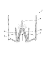
- the gas mist supply pipe 57 can be freely bent and expanded and contracted if the whole or part of the gas mist supply pipe 57 is formed of a flexible bellows-like pipe having a large pipe diameter as shown in FIG. There is no limit. Further, even if the gas mist flowing through the gas mist supply pipe 57 is liquefied, it is possible to remove the liquid from the irregular portions of the bellows.
- FIG. 9 is an overall schematic diagram of a gas mist inhaler according to a second embodiment of the present invention.
- the same parts as those of the first embodiment shown in FIGS. 1 to 8 are denoted by the same reference numerals, and detailed description thereof is omitted.
- the gas mist inhaler 20 ⁇ / b> A of this embodiment includes a gas supply device 32 as a gas supply means 30, a gas mist generator 40 as a gas mist generation means, and an intake mask 51 as an intake member 50.
- a gas supply device 32 as a gas supply means
- a gas mist generator 40 as a gas mist generation means
- an intake mask 51 as an intake member 50.
- the gas supply device 32 is a stationary device for supplying a gas (oxygen, carbon dioxide, or a mixed gas of oxygen and carbon dioxide) to the gas mist generator 40 at a predetermined pressure.
- a gas cylinder (not shown) is built in the inside. Further, a compressor may be incorporated. Alternatively, it may be connected to an external gas cylinder or the like.
- the gas supply device 32 includes a power switch 33, an oxygen supply ON / OFF switch 34, a carbon dioxide supply ON / OFF switch 35, a gas mixture ratio setting unit 36, an OFF timer (gas supply time setting unit). 37) and a gas supply pressure adjusting unit 38. That is, in the present embodiment, the gas supply device connection portion is not provided with a dial switch or a fuel gauge (gas supply device connection portion 45 ′), and various adjustments are made by the gas supply device 32. Further, the gas supply device 32 and the gas mist generator 40 are connected by a gas supply pipe 39.
- the gas mixing ratio setting unit 36 is configured so that the mixing ratio of carbon dioxide gas and oxygen can be arbitrarily set. Thus, for example, when using for the purpose of asthma and fatigue recovery, set a higher oxygen mixing ratio, or when using it for the purpose of promoting respiratory blood flow, increase the mixing ratio of carbon dioxide. It is possible to freely set and respond to the purpose of the user.
- the OFF timer 37 is for setting the gas supply time, and automatically stops the gas supply when the set time elapses. Further, the gas supply pressure adjusting unit 38 can arbitrarily set the gas supply pressure. Thereby, since the supply time and supply pressure of gas can be set, the range of the purpose of use can be widened.
- the gas supplied from the gas supply device 32 is branched into two at the gas supply means connecting portion 45, but instead, the gas supply device 32 is shown.
- the gas may be directly supplied to the nozzle 43 and the gas introduction part 47 separately. In that case, the same gas may be supplied by the nozzle 43 and the gas introduction part 47, or different gases may be supplied.
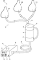
- FIG. 10 is an overall schematic diagram of a gas mist inhaler according to a third embodiment of the present invention.
- symbol is attached
- a gas mist inhaler 20B includes a gas supply device 32 as a gas supply means 30, a gas mist generator 40 as a gas mist generation means, and a plurality of suction members 50 (here as examples) A plurality of suction masks 51A to 51C).
- a gas mist supply pipe 58 branched into a plurality (three here) is provided between the gas mist generator 40 and a plurality (three here) of the suction members 50.
- a plurality of suction masks 51A, 51B, 51C can be connected to one gas supply device 32 and gas mist generator 40.
- the gas supply pressure adjusting unit 38 adjusts the gas supply pressure so that the gas mist can be optimally sucked in each of the plurality of suction masks 51A, 51B, 51C.
- a gas mist may be supplied to the plurality of suction members by providing a plurality of branched pipes in the middle of the normal gas mist supply pipe.
- the physiological action of the gas mist not only allows the medicinal solution to penetrate into the upper and lower airways, but also reduces the blood flow in the affected area. Actively, it can exert effects such as suppressing inflammation quickly and increasing immunity.
- the liquid storage part that is a part of the gas mist generator can be removed and replaced with another liquid storage part, and the used liquid storage part can be replaced.
- the liquid storage part can be removed and replaced with another liquid storage part, and the used liquid storage part can be replaced.
- the present invention relates to a gas mist inhaler for orally inhaling a gas mist obtained by pulverizing and dissolving a liquid such as oxygen, carbon dioxide gas, or a mixed gas of oxygen and carbon dioxide gas and a medicine, and has industrial applicability.
Landscapes
- Health & Medical Sciences (AREA)
- Public Health (AREA)
- Animal Behavior & Ethology (AREA)
- Veterinary Medicine (AREA)
- General Health & Medical Sciences (AREA)
- Life Sciences & Earth Sciences (AREA)
- Engineering & Computer Science (AREA)
- Hematology (AREA)
- Heart & Thoracic Surgery (AREA)
- Biomedical Technology (AREA)
- Anesthesiology (AREA)
- Pulmonology (AREA)
- Emergency Medicine (AREA)
- Pain & Pain Management (AREA)
- Epidemiology (AREA)
- Physical Education & Sports Medicine (AREA)
- Rehabilitation Therapy (AREA)
- Bioinformatics & Cheminformatics (AREA)
- Devices For Medical Bathing And Washing (AREA)
- Pharmaceuticals Containing Other Organic And Inorganic Compounds (AREA)
- Medicinal Preparation (AREA)
- Containers And Packaging Bodies Having A Special Means To Remove Contents (AREA)
Abstract
Description
図1は、本発明の第1の実施形態に係るガスミスト吸入器の全体概略図である。
上記第1の実施形態では、ガス供給手段30として小型のカートリッジ式ガスボンベ31を用いる例を示したが、本実施形態では、据置型のガス供給装置を用いる例について示す。
上記第2の実施形態では、一つのガスミスト生成器40に対して一つの吸入部材50を接続する例を示したが、本実施形態では、複数の吸入部材を接続する構成について説明する。
20A ガスミスト吸入器
30 ガス供給手段
31 ガスボンベ
32 ガス供給装置
33 電源スイッチ
34 酸素供給ON/OFFスイッチ
35 炭酸ガス供給ON/OFFスイッチ
36 ガス混合比設定部
37 OFFタイマー(ガス供給時間設定部)
38 ガス供給圧調整部
39 ガス供給管
40 ガスミスト生成器
41 生成器本体
41A、41B 栓
41C フィルム
42 液体貯留部
43 ノズル
43A 先端開口
44 吸液管形成部材
44A 吸液管
45、45′ ガス供給手段接続部
45A ガス吐出口
45B 分岐部
45C 流量調整部
451 ダイヤルスイッチ
452 残量ゲージ
46 蓋部
47 ガス導入部
48 バッフル(衝突部材)
48A バッフル支持部
49 ガスミスト排出部
50 吸入部材
51、51A、51B、51C 吸入マスク
52、52A、52B 接続部
53、53A、53B 吸入口
54、54A、54B 開口
55 口用マスク
56 鼻用マスク
57 ガスミスト供給管
58 ガスミスト供給管
Claims (13)
- 酸素、炭酸ガス、又は酸素と炭酸ガスの混合ガス(以下、「ガス」という)を供給するガス供給手段と、
該ガス供給手段との接続部と、液体を貯留する液体貯留部と、前記ガスが供給されるノズルと、該ノズル先端に前記液体を送液する吸液管と、前記ノズルからのガス流によって吹き上げられた液体を衝突させて前記液体と前記ガスとを粉砕溶解させたミスト(以下、「ガスミスト」という)にする衝突部材と、前記ガスが供給され前記ノズルの上部までガスを導く円筒状のガス導入部と、前記ガスミストを収集及び排出するドーナツ形のガスミスト排出部と、を有するガスミスト生成手段と、
該ガスミスト生成手段と接続され、前記ガスミストを生体に吸入させるための吸入口を有する吸入部材と、を備え、
前記ガスミスト生成手段において、少なくとも前記液体貯留部を取り外し可能にして他の液体貯蔵部と取替え可能に構成したことを特徴とするガスミスト吸入器。 - 前記ガスミスト生成手段が、外気を取り込むための通気孔を備えることを特徴とする請求項1に記載のガスミスト吸入器。
- 前記吸入部材が、外気を取り込むための開口をさらに有することを特徴とする請求項1に記載のガスミスト吸入器。
- 前記ガス供給手段が、カートリッジ式ガスボンベであることを特徴とする請求項1乃至3の何れか1項に記載のガスミスト吸入器。
- 前記ガス供給手段が、ガス供給時間設定部、ガス供給圧調整部、ガス混合比設定部の何れか一つ又は複数を備えることを特徴とする請求項1乃至4の何れか1項に記載のガスミスト吸入器。
- 前記ガスミスト生成手段が、複数の前記吸入部材にガスミストを供給することを特徴とする請求項5に記載のガスミスト吸入器。
- 前記液体は、水、イオン水、オゾン水、生理食塩水、精製水、又は滅菌精製水の何れか一つ又は複数の組み合わせであることを特徴とする請求項1に記載のガスミスト吸入器。
- 前記液体は、メンソール、ビタミンE、ビタミンC誘導体、レチノール、麻酔薬、シクロデキストリン、光触媒、光触媒とアパタイトの複合体、ヒアルロン酸、コエンザイムQ10、シードオイル、プロポリス、エタノール、グルコン酸クロルヘキシジン、両性界面活性剤、塩化ベンザルコニウム、酢酸アルキルジアミノエテルグリシン、次亜塩素酸ナトリウム、過酢酸、セスキ炭酸ナトリウム、シリカ、ポピドンヨード、炭酸水素ナトリウム、高濃度炭酸泉剤、抗アレルギー剤、抗炎症剤、解熱鎮痛剤、抗真菌剤、抗インフルエンザウィルス剤、インフルエンザワクチン、ステロイド剤、抗ガン剤、又は血圧降下剤のうち、何れか一つ又は複数をさらに含有することを特徴とする請求項7に記載のガスミスト吸入器。
- 前記ガスミスト生成手段から前記吸入部材内に供給される前記ミストの粒径が、10μm以下であることを特徴とする請求項1に記載のガスミスト吸入器。
- 前記ガスミスト生成手段が、前記吸入部材へガスミストを供給するためのガスミスト供給管を有し、
該ガスミスト供給管が、管内に付着する液滴を除去するためのフィルターを備えることを特徴とする請求項1に記載のガスミスト吸入器。 - 前記ガスミスト生成手段が、前記吸入部材へガスミストを供給するためのガスミスト供給管を有し、
該ガスミスト供給管の全部又は一部がジャバラ状の管から構成されることを特徴とする請求項1に記載のガスミスト吸入器。 - 前記ガスミスト生成手段が、前記吸入部材へガスミストを供給するためのガスミスト供給管を有し、
該ガスミスト供給管に、逆止弁を設けることを特徴とする請求項1に記載のガスミスト吸入器。 - 前記ガスミスト生成手段の取り外し可能部分が、予め滅菌処理されていることを特徴とする請求項1に記載のガスミスト吸入器。
Priority Applications (4)
| Application Number | Priority Date | Filing Date | Title |
|---|---|---|---|
| KR1020137010576A KR20130116257A (ko) | 2011-01-21 | 2012-01-20 | 가스 미스트 흡입기 |
| US13/884,494 US20130228176A1 (en) | 2011-01-21 | 2012-01-20 | Gas mist inhaler |
| CN201280003202.0A CN103153256B (zh) | 2011-01-21 | 2012-01-20 | 气雾吸入器 |
| EP12736793.6A EP2626052A1 (en) | 2011-01-21 | 2012-01-20 | Gas mist inhaler |
Applications Claiming Priority (2)
| Application Number | Priority Date | Filing Date | Title |
|---|---|---|---|
| JP2011-010647 | 2011-01-21 | ||
| JP2011010647A JP5102376B2 (ja) | 2011-01-21 | 2011-01-21 | ガスミスト吸入器 |
Publications (1)
| Publication Number | Publication Date |
|---|---|
| WO2012099250A1 true WO2012099250A1 (ja) | 2012-07-26 |
Family
ID=46515867
Family Applications (1)
| Application Number | Title | Priority Date | Filing Date |
|---|---|---|---|
| PCT/JP2012/051247 WO2012099250A1 (ja) | 2011-01-21 | 2012-01-20 | ガスミスト吸入器 |
Country Status (6)
| Country | Link |
|---|---|
| US (1) | US20130228176A1 (ja) |
| EP (1) | EP2626052A1 (ja) |
| JP (1) | JP5102376B2 (ja) |
| KR (1) | KR20130116257A (ja) |
| CN (1) | CN103153256B (ja) |
| WO (1) | WO2012099250A1 (ja) |
Families Citing this family (11)
| Publication number | Priority date | Publication date | Assignee | Title |
|---|---|---|---|---|
| CA2856196C (en) | 2011-12-06 | 2020-09-01 | Masco Corporation Of Indiana | Ozone distribution in a faucet |
| DE102014005872A1 (de) * | 2014-04-23 | 2015-10-29 | Attila MARKUS | Verfahren und Vorrichtung zum gerichteten Leiten von Bienenstockluft sowie Verwendung als Inhalator |
| GB201419455D0 (en) * | 2014-10-28 | 2014-12-17 | Linde Ag | A gas fed atomiser |
| CN108463437B (zh) | 2015-12-21 | 2022-07-08 | 德尔塔阀门公司 | 包括消毒装置的流体输送系统 |
| CN105509174A (zh) * | 2016-01-14 | 2016-04-20 | 成都三千米甜蜂业有限公司 | 一种蜂胶空气净化器 |
| CN106178210A (zh) * | 2016-08-08 | 2016-12-07 | 珠海威泓医疗科技有限公司 | 气体中毒急救呼吸机 |
| TWI709420B (zh) * | 2019-02-21 | 2020-11-11 | 國立清華大學 | 電漿氣霧吸入裝置及電漿液用於製造氣霧吸入劑之用途 |
| KR102216547B1 (ko) | 2019-05-09 | 2021-02-17 | 숙명여자대학교산학협력단 | 에어로졸 생성방법 및 장치 |
| CN110124165B (zh) * | 2019-05-15 | 2021-10-29 | 西安交通大学医学院第一附属医院 | 一种便携式肺癌定量雾化装置 |
| IT202000020041A1 (it) * | 2020-08-12 | 2022-02-12 | 3A Health Care S R L | Dispositivo per aerosolterapia |
| CN117482341B (zh) * | 2024-01-03 | 2024-03-22 | 吉林大学 | 一种带有辅助张嘴结构的儿童雾化器 |
Citations (3)
| Publication number | Priority date | Publication date | Assignee | Title |
|---|---|---|---|---|
| JP2000245841A (ja) * | 1999-02-26 | 2000-09-12 | Kao Corp | アイケア用噴霧装置 |
| WO2010098430A1 (ja) * | 2009-02-26 | 2010-09-02 | 日本エー・シー・ピー株式会社 | ガスミスト吸入器 |
| JP3163837U (ja) * | 2010-08-23 | 2010-11-04 | 中村 正一 | ガスミスト圧浴用カバー |
Family Cites Families (15)
| Publication number | Priority date | Publication date | Assignee | Title |
|---|---|---|---|---|
| US3713440A (en) * | 1971-01-18 | 1973-01-30 | P Nicholes | Filtration system |
| US4392490A (en) * | 1981-02-23 | 1983-07-12 | Mattingly Glen R | Multiple outlet connecting means for self-contained positive pressure or demand regulated breathing apparatus |
| US4886055A (en) * | 1988-01-22 | 1989-12-12 | Hoppough John M | Nebulizer device |
| US4938209A (en) * | 1989-01-12 | 1990-07-03 | Fry William J | Mask for a nebulizer |
| US5357945A (en) * | 1993-03-17 | 1994-10-25 | Messina Robin L | Multipositional nebulizer device |
| US5584285A (en) * | 1995-06-07 | 1996-12-17 | Salter Labs | Breathing circuit apparatus for a nebulizer |
| US5586551A (en) * | 1995-07-17 | 1996-12-24 | Hilliard; Kenneth R. | Oxygen mask with nebulizer |
| DE10239321B3 (de) * | 2002-08-27 | 2004-04-08 | Pari GmbH Spezialisten für effektive Inhalation | Aerosoltherapievorrichtung |
| WO2006014167A2 (en) * | 2004-07-06 | 2006-02-09 | Wright Vivian A | Face and tracheostomy nebulizing mask |
| US7669595B1 (en) * | 2006-04-03 | 2010-03-02 | Mitchell Bryon L | Junction device |
| WO2008028092A2 (en) * | 2006-08-30 | 2008-03-06 | Kurve Technology, Inc. | Aerosol generating and delivery device |
| JP5023747B2 (ja) * | 2007-03-13 | 2012-09-12 | オムロンヘルスケア株式会社 | ネブライザ用吸入補助具 |
| JP5419236B2 (ja) * | 2009-07-29 | 2014-02-19 | 正一 中村 | ガスミストマスク装置 |
| CN201701589U (zh) * | 2010-06-02 | 2011-01-12 | 天卓睿丰医疗科技(北京)有限公司 | 呼吸道给药的喷雾器 |
| RU2012122209A (ru) * | 2010-07-01 | 2013-12-10 | ЭйСиПи ДЖЭПЭН КО., ЛТД. | Газо-аэрозольная ванная система давления |
-
2011
- 2011-01-21 JP JP2011010647A patent/JP5102376B2/ja active Active
-
2012
- 2012-01-20 KR KR1020137010576A patent/KR20130116257A/ko not_active Application Discontinuation
- 2012-01-20 WO PCT/JP2012/051247 patent/WO2012099250A1/ja active Application Filing
- 2012-01-20 US US13/884,494 patent/US20130228176A1/en not_active Abandoned
- 2012-01-20 CN CN201280003202.0A patent/CN103153256B/zh not_active Expired - Fee Related
- 2012-01-20 EP EP12736793.6A patent/EP2626052A1/en not_active Withdrawn
Patent Citations (3)
| Publication number | Priority date | Publication date | Assignee | Title |
|---|---|---|---|---|
| JP2000245841A (ja) * | 1999-02-26 | 2000-09-12 | Kao Corp | アイケア用噴霧装置 |
| WO2010098430A1 (ja) * | 2009-02-26 | 2010-09-02 | 日本エー・シー・ピー株式会社 | ガスミスト吸入器 |
| JP3163837U (ja) * | 2010-08-23 | 2010-11-04 | 中村 正一 | ガスミスト圧浴用カバー |
Also Published As
| Publication number | Publication date |
|---|---|
| EP2626052A1 (en) | 2013-08-14 |
| CN103153256A (zh) | 2013-06-12 |
| CN103153256B (zh) | 2017-07-21 |
| KR20130116257A (ko) | 2013-10-23 |
| JP5102376B2 (ja) | 2012-12-19 |
| JP2012148021A (ja) | 2012-08-09 |
| US20130228176A1 (en) | 2013-09-05 |
Similar Documents
| Publication | Publication Date | Title |
|---|---|---|
| JP5102376B2 (ja) | ガスミスト吸入器 | |
| JP5674637B2 (ja) | ガスミスト吸入器 | |
| JP5892933B2 (ja) | ガスミスト吸入器 | |
| JP5475765B2 (ja) | ガスミスト吸入器 | |
| JP5368661B1 (ja) | ガスミスト吸入器 | |
| JP5419236B2 (ja) | ガスミストマスク装置 | |
| TW201313265A (zh) | 吸入系統、呼吸裝置及方法 | |
| CN104208778A (zh) | 用于呼吸回路的雾化给药系统 | |
| CN204106767U (zh) | 用于呼吸回路的雾化给药系统 | |
| JP2020124354A (ja) | ガスミスト発生装置 | |
| JP2020124353A (ja) | ガスミスト発生装置 | |
| CN202875995U (zh) | 新型雾化吸入器 | |
| CN201988004U (zh) | 硬质单向阀式气雾剂助吸器 | |
| JP2020124355A (ja) | ガスミスト発生装置 |
Legal Events
| Date | Code | Title | Description |
|---|---|---|---|
| WWE | Wipo information: entry into national phase |
Ref document number: 201280003202.0 Country of ref document: CN |
|
| 121 | Ep: the epo has been informed by wipo that ep was designated in this application |
Ref document number: 12736793 Country of ref document: EP Kind code of ref document: A1 |
|
| ENP | Entry into the national phase |
Ref document number: 20137010576 Country of ref document: KR Kind code of ref document: A |
|
| WWE | Wipo information: entry into national phase |
Ref document number: 13884494 Country of ref document: US Ref document number: 2012736793 Country of ref document: EP |
|
| NENP | Non-entry into the national phase |
Ref country code: DE |