WO2012093705A1 - マルチポンプユニット、タンデムポンプユニット及び作業車輌 - Google Patents
マルチポンプユニット、タンデムポンプユニット及び作業車輌 Download PDFInfo
- Publication number
- WO2012093705A1 WO2012093705A1 PCT/JP2012/050131 JP2012050131W WO2012093705A1 WO 2012093705 A1 WO2012093705 A1 WO 2012093705A1 JP 2012050131 W JP2012050131 W JP 2012050131W WO 2012093705 A1 WO2012093705 A1 WO 2012093705A1
- Authority
- WO
- WIPO (PCT)
- Prior art keywords
- pump
- hydraulic
- port
- pair
- oil
- Prior art date
- Legal status (The legal status is an assumption and is not a legal conclusion. Google has not performed a legal analysis and makes no representation as to the accuracy of the status listed.)
- Ceased
Links
Images









Classifications
-
- F—MECHANICAL ENGINEERING; LIGHTING; HEATING; WEAPONS; BLASTING
- F16—ENGINEERING ELEMENTS AND UNITS; GENERAL MEASURES FOR PRODUCING AND MAINTAINING EFFECTIVE FUNCTIONING OF MACHINES OR INSTALLATIONS; THERMAL INSULATION IN GENERAL
- F16H—GEARING
- F16H39/00—Rotary fluid gearing using pumps and motors of the volumetric type, i.e. passing a predetermined volume of fluid per revolution
- F16H39/02—Rotary fluid gearing using pumps and motors of the volumetric type, i.e. passing a predetermined volume of fluid per revolution with liquid motors at a distance from liquid pumps
-
- B—PERFORMING OPERATIONS; TRANSPORTING
- B60—VEHICLES IN GENERAL
- B60K—ARRANGEMENT OR MOUNTING OF PROPULSION UNITS OR OF TRANSMISSIONS IN VEHICLES; ARRANGEMENT OR MOUNTING OF PLURAL DIVERSE PRIME-MOVERS IN VEHICLES; AUXILIARY DRIVES FOR VEHICLES; INSTRUMENTATION OR DASHBOARDS FOR VEHICLES; ARRANGEMENTS IN CONNECTION WITH COOLING, AIR INTAKE, GAS EXHAUST OR FUEL SUPPLY OF PROPULSION UNITS IN VEHICLES
- B60K17/00—Arrangement or mounting of transmissions in vehicles
- B60K17/04—Arrangement or mounting of transmissions in vehicles characterised by arrangement, location or kind of gearing
- B60K17/043—Transmission unit disposed in on near the vehicle wheel, or between the differential gear unit and the wheel
-
- B—PERFORMING OPERATIONS; TRANSPORTING
- B60—VEHICLES IN GENERAL
- B60K—ARRANGEMENT OR MOUNTING OF PROPULSION UNITS OR OF TRANSMISSIONS IN VEHICLES; ARRANGEMENT OR MOUNTING OF PLURAL DIVERSE PRIME-MOVERS IN VEHICLES; AUXILIARY DRIVES FOR VEHICLES; INSTRUMENTATION OR DASHBOARDS FOR VEHICLES; ARRANGEMENTS IN CONNECTION WITH COOLING, AIR INTAKE, GAS EXHAUST OR FUEL SUPPLY OF PROPULSION UNITS IN VEHICLES
- B60K17/00—Arrangement or mounting of transmissions in vehicles
- B60K17/04—Arrangement or mounting of transmissions in vehicles characterised by arrangement, location or kind of gearing
- B60K17/10—Arrangement or mounting of transmissions in vehicles characterised by arrangement, location or kind of gearing of fluid gearing
-
- B—PERFORMING OPERATIONS; TRANSPORTING
- B60—VEHICLES IN GENERAL
- B60K—ARRANGEMENT OR MOUNTING OF PROPULSION UNITS OR OF TRANSMISSIONS IN VEHICLES; ARRANGEMENT OR MOUNTING OF PLURAL DIVERSE PRIME-MOVERS IN VEHICLES; AUXILIARY DRIVES FOR VEHICLES; INSTRUMENTATION OR DASHBOARDS FOR VEHICLES; ARRANGEMENTS IN CONNECTION WITH COOLING, AIR INTAKE, GAS EXHAUST OR FUEL SUPPLY OF PROPULSION UNITS IN VEHICLES
- B60K7/00—Disposition of motor in, or adjacent to, traction wheel
- B60K7/0015—Disposition of motor in, or adjacent to, traction wheel the motor being hydraulic
-
- F—MECHANICAL ENGINEERING; LIGHTING; HEATING; WEAPONS; BLASTING
- F04—POSITIVE - DISPLACEMENT MACHINES FOR LIQUIDS; PUMPS FOR LIQUIDS OR ELASTIC FLUIDS
- F04B—POSITIVE-DISPLACEMENT MACHINES FOR LIQUIDS; PUMPS
- F04B23/00—Pumping installations or systems
- F04B23/04—Combinations of two or more pumps
- F04B23/06—Combinations of two or more pumps the pumps being all of reciprocating positive-displacement type
-
- F—MECHANICAL ENGINEERING; LIGHTING; HEATING; WEAPONS; BLASTING
- F16—ENGINEERING ELEMENTS AND UNITS; GENERAL MEASURES FOR PRODUCING AND MAINTAINING EFFECTIVE FUNCTIONING OF MACHINES OR INSTALLATIONS; THERMAL INSULATION IN GENERAL
- F16H—GEARING
- F16H61/00—Control functions within control units of change-speed- or reversing-gearings for conveying rotary motion ; Control of exclusively fluid gearing, friction gearing, gearings with endless flexible members or other particular types of gearing
- F16H61/38—Control of exclusively fluid gearing
- F16H61/40—Control of exclusively fluid gearing hydrostatic
- F16H61/44—Control of exclusively fluid gearing hydrostatic with more than one pump or motor in operation
- F16H61/448—Control circuits for tandem pumps or motors
-
- B—PERFORMING OPERATIONS; TRANSPORTING
- B60—VEHICLES IN GENERAL
- B60K—ARRANGEMENT OR MOUNTING OF PROPULSION UNITS OR OF TRANSMISSIONS IN VEHICLES; ARRANGEMENT OR MOUNTING OF PLURAL DIVERSE PRIME-MOVERS IN VEHICLES; AUXILIARY DRIVES FOR VEHICLES; INSTRUMENTATION OR DASHBOARDS FOR VEHICLES; ARRANGEMENTS IN CONNECTION WITH COOLING, AIR INTAKE, GAS EXHAUST OR FUEL SUPPLY OF PROPULSION UNITS IN VEHICLES
- B60K7/00—Disposition of motor in, or adjacent to, traction wheel
- B60K2007/0061—Disposition of motor in, or adjacent to, traction wheel the motor axle being parallel to the wheel axle
Definitions
- the present invention relates to a multi-pump unit including first and second hydraulic pumps, a tandem pump unit in which first and second hydraulic pumps are arranged in series, and a working vehicle including the tandem pump unit.
- Patent Document 1 discloses a tandem type multi-pump unit in which first and second hydraulic pumps are arranged in series. ing.
- the tandem multi-pump unit described in Patent Document 1 includes a first hydraulic circuit in which pressure oil supplied from a single charge pump and hydraulically set by a single relief valve is formed by a first hydraulic pump; It is configured to be supplied to both the second hydraulic circuit formed by the second hydraulic pump unit, and is useful in that the charge oil supply structure to the first and second hydraulic circuits can be simplified. is there.
- the multi-pump unit described in Patent Document 1 has a problem that the first and second hydraulic pumps can be used only in a mode in which they are arranged in series, and the versatility of the constituent members is poor.
- Patent Document 1 discloses a tandem type multi-pump unit according to first and second embodiments.
- the pump unit according to the first embodiment surrounds the single port block, the first hydraulic pump slidably in contact with the first end surface on one side in the thickness direction of the port block, and the first hydraulic pump.
- a first pump case connected to the first end surface of the port block, a second hydraulic pump slidably in contact with the second end surface on the other side in the thickness direction of the port block, and surrounding the second hydraulic pump
- a second pump case connected to the second end face of the port block.
- the single port block is a common member for both the first and second hydraulic pumps, and thus the first and second hydraulic pumps are independent. Cannot be installed. Furthermore, the single port block is a member dedicated to the tandem pump unit according to the first embodiment, and lacks versatility.
- the pump unit according to the second embodiment has first and second hydraulic pumps, a first opening through which the first hydraulic pump can be inserted on one side in the axial direction, and the second hydraulic pump on the other side in the axial direction.
- a single pump case having a second opening through which the hydraulic pump can be inserted, and a first port block connected to the pump case so as to close the first opening in a state where the first hydraulic pump is slidably contacted
- a second port block connected to the pump case so as to close the second opening while the second hydraulic pump is in sliding contact.
- the single pump case is a member that accommodates both the first and second hydraulic pumps. Therefore, similarly to the first embodiment, the first pump case is the same as the first embodiment. And the 2nd hydraulic pump cannot be installed independently. Furthermore, the single pump case is a member dedicated to the pump unit according to the second embodiment, and lacks versatility.
- the first hydraulic pump operatively drives one of a pair of drive wheels.
- a first HST is formed in cooperation with the first hydraulic motor
- a second HST is formed in cooperation with a second hydraulic motor in which the second hydraulic pump operatively drives the other of the pair of drive wheels. Therefore, the tandem pump unit is provided with a charge pump that acts as a charge oil source for the first and second HSTs.
- the conventional configuration includes a pair of hydraulic oil passages for the first hydraulic pump that form part of the pair of hydraulic oil lines in the first HST, and a portion of the pair of hydraulic oil lines in the second HST.
- the oil pressure is set by the single relief valve.
- the relief valve is arranged on one side in the rotational axis direction of the first and second hydraulic pumps arranged in series, and the drain oil from the relief valve is supplied to the first and second hydraulic pumps.
- the two hydraulic pumps are discharged into one pump space that houses the hydraulic pump on the side close to the relief valve.
- the conventional configuration is provided with an oil circulation hole that fluidly connects the one pump space to the other pump space that houses the hydraulic pump on the side separated from the relief valve of the first and second hydraulic pumps.
- the drain oil that has flowed into the one pump space from the relief valve reaches both the one pump space and the other pump space.
- Patent Document 1 discloses and suggests that the stored oil in the one pump space and the other pump space is actively circulated to effectively prevent the temperature rise of the stored oil. Absent.
- the present invention has been made in view of such a conventional technique, and enables the first and second hydraulic pressures to be set with a single relief valve for the hydraulic pressures of the charge oil passages of both the first and second hydraulic pumps.
- the present invention is a tandem pump unit in which a first and a second hydraulic pump are arranged in series, and the first and second hydraulic pumps are accommodated while reducing costs by reducing the number of parts.
- a second object of the present invention is to provide a tandem pump unit that can effectively prevent the temperature rise of stored oil in the second pump space, and a working vehicle including the tandem pump unit.
- the present invention provides a first hydraulic pump, a first end surface in which the first hydraulic pump is in direct or indirect sliding contact, and a second end opposite to the first end surface in the thickness direction.
- a first port block having an end face; a first pump case coupled to the first end face of the first port block so as to surround the first hydraulic pump; a second hydraulic pump; and the second hydraulic pump.
- a second port block having a first end surface that is in direct or indirect sliding contact and a second end surface opposite to the first end surface in the thickness direction, and a second port block of the second port block so as to surround the second hydraulic pump.
- a multi-pump unit including a second pump case coupled to one end face, wherein the first and second port blocks are configured such that a pump shaft for driving a corresponding hydraulic pump is inserted through the first and second port blocks.
- Two ends An axial hole passing therethrough and an opening at the first end surface extending in the direction of the first plate surface of the port block in a symmetric state with respect to the axial hole and fluidly connected to the hydraulic pump.
- a pair of operating oil passages having one pair of parallel portions and having one end portion opened to the outer surface to form a pair of supply / discharge ports, and one end portion opened to the outer surface to form a pressure oil receiving port
- Charge oil passages whose ends are branched and fluidly connected to the pair of hydraulic oil passages via check valves, respectively, one end is fluidly connected to the charge oil passage, and the other end is open to the second end face
- a branch oil passage that forms a connection port, and the connection port passes through the axis of the axial hole and is virtually along the first plate surface direction and the thickness direction of the port block.
- said One of the pressure oil receiving port of the one-port block and one of the pressure oil receiving ports of the second port block are fluidly connected to a pressure oil supply source and the other is closed by a plug, and one of the first and second port blocks
- the multi-pump unit is provided with a relief valve for setting the oil pressure of the charge oil passage only in the cylinder.
- the first and second hydraulic pumps can perform the hydraulic setting of the charge oil passages of both the first and second port blocks by a single relief valve.
- a tandem configuration arranged in series and an independent installation configuration in which the first and second hydraulic pumps are arranged independently of each other can be selected.
- the connection ports of both port blocks are connected by connecting both port blocks in a state where the second end surfaces of the first and second port blocks are in contact with each other.
- the oil pressure setting of both charge oil passages can be realized by the single relief valve without providing an additional member.
- the relief valve from which the relief oil from the relief valve is guided to one pump space formed by the one port block and the corresponding pump case, and the relief oil is mounted on the relief valve.
- a second relief drain oil passage is provided for guiding to the other pump space formed by the other port block and the corresponding pump case.
- the first relief drain oil passage has the one port so that one end is fluidly connected to the relief valve and the other end is open to the first end surface and fluidly connected to the one pump space. Formed into blocks.
- the second relief drain oil passage has an upstream portion formed at the one port block such that one end portion is fluidly connected to the relief valve and the other end portion opens to the second end face, and one end portion Is formed in the other port block so as to be fluidly connected to the upstream portion and the other end is opened to the first end surface and fluidly connected to the other pump space.
- At least one of the one port block and the corresponding pump case is formed with a drain port that opens the pump space formed by both, and at least one of the other port block and the corresponding pump case is formed by both.
- a drain port is formed which opens the pump space to the outside.
- each of the first and second port blocks has first to fourth side faces extending in the thickness direction and connecting the peripheral edges of the first and second end faces.
- the first and second side surfaces respectively face the one side and the other side in the first plate surface direction
- the third and fourth side surfaces respectively have a second plate surface direction one side orthogonal to the first plate surface direction and Look to the other side.
- each of the first and second port blocks extends in the first plate surface direction in a state of being symmetrical with respect to each other with the axial hole interposed therebetween, and one end portion and the other end portion of the first and second port blocks have the first and second ends, respectively.
- a pair of first perforations opened in the second side surface and the second plate surface direction so as to communicate between the pair of first perforations on the side closer to the second side surface than the axial hole.
- a second perforation having one end and the other end opened in the third and fourth side surfaces, and one end opened in the second side and the other end fluidly connected to the second perforation.
- a third perforation and a fourth perforation that has one end fluidly connected to the third perforation and the other end opened to the second end face to form the branch oil passage are formed.
- the pair of first perforations form the pair of hydraulic fluid passages whose one end portion functions as the supply / discharge port by closing the other end portion with a plug.
- the second perforation and the third perforation are performed with one end of the third perforation acting as the pressure oil receiving port.
- the charge oil passage is formed.
- one of the port blocks to which the relief valve is mounted has one end opened to the third side surface and the other end fluidly connected to the third perforation.
- a fifth perforation extending along the second plate surface direction on the side closer to the second side surface than the axial hole, and forming a relief valve insertion hole into which the relief valve is inserted from the one end portion
- a sixth perforation having one end and the other end opened to the first and second end surfaces in a state of passing through the fifth perforation, while the relief valve is not mounted
- the port block is provided with a seventh perforation having one end opened at the second end face and the other end opened at the first end face so as to be fluidly connected to the other end of the sixth perforation.
- a portion of the sixth perforation that is located closer to the first end surface than the fifth perforation forms the first relief drain oil passage, and the sixth perforation is located closer to the second end surface than the fifth perforation. And the seventh perforation form the second relief drain oil passage.
- each of the first and second port blocks is formed with an eighth perforation extending in the second plate surface direction on the side closer to the first side surface than the axial hole.
- the eighth perforation is a bypass that is fluidly connected to both of the pair of hydraulic fluid passages with one end opened to one of the third or fourth side surfaces, and is inserted from the one end of the eighth perforation.
- the valve selectively connects or disconnects the fluid between the pair of hydraulic fluid passages.
- the present invention includes a first hydraulic pump and a first hydraulic pump that are slidably in contact with end faces on one side and the other side in the thickness direction of the port block and the port block, respectively.
- a first pump case coupled to the port block so as to form a first pump space to be accommodated and a second pump coupled to the port block so as to form a second pump space for accommodating the second hydraulic pump.
- a tandem pump unit including a case, wherein the port block includes a pair of supply / exhaust ports having at least one end opened to an outer surface in fluid connection with the first hydraulic pump.
- a first hydraulic pump for supplying hydraulic oil from a first hydraulic pump and a hydraulic oil for a pair of first hydraulic pumps via a check valve.
- 2 relief drain oil passages are provided, and at least one of the port block and the first pump case is provided with a first pump side drain port that opens the first pump space to the outside, and the port block At least one of the fine the second pump casing to provide a tandem pump unit the second pump-side drain port opening said second pump space to the outside.
- the hydraulic pressures of both the first hydraulic pump charge oil passage and the second hydraulic pump charge oil passage in the port block positioned between the first and second hydraulic pumps in the axial direction.
- An increase in the oil temperature of the stored oil due to efficient circulation of the stored oil can be suppressed.
- the port block includes a first port block having a first end surface in the thickness direction in which the first hydraulic pump is slidably contacted, and a second end surface opposite to the first end surface in the thickness direction, and the second hydraulic pressure.
- the present invention provides a first hydraulic motor that forms a first HST in cooperation with the tandem pump unit, an engine that is a power source of the tandem pump unit, a pair of left and right drive wheels, and the first hydraulic pump.
- a first hydraulic motor unit that outputs rotational power of the first hydraulic motor toward one of the pair of drive wheels, and a second hydraulic pressure that cooperates with the second hydraulic pump to form a second HST.
- a second hydraulic motor unit having a motor and outputting rotational power of the second hydraulic motor toward the other of the pair of drive wheels; and the first and second hydraulic pumps operatively driven by the engine
- a working vehicle comprising a charge pump that acts as a pressure oil supply source for a charge oil passage, and an oil tank that acts as an oil source for the charge pump, wherein the first hydraulic motor unit A pair of first motor-side drain ports that open the first motor space that houses the first hydraulic motor to the outside is provided in the second motor, and the second motor that houses the second hydraulic motor is provided in the second hydraulic motor unit.
- a pair of second motor side drain ports that open the space to the outside are provided, the first pump side drain port is fluidly connected to one of the pair of first motor side drain ports, and the pair of first motor side drain ports The other of the pair of second motor side drain ports is fluidly connected to one of the pair of second motor side drain ports, and the other of the pair of second motor side drain ports is fluidly connected to the oil tank.
- a working vehicle that is fluidly connected to the vehicle is provided.
- the first pump side drain port in the tandem pump unit is fluidly connected to one of the pair of first motor side drain ports in the first hydraulic motor unit, and the pair of first motors.
- the other side drain port is fluidly connected to the oil tank
- the second pump side drain port in the tandem pump unit is fluidly connected to one of the pair of second motor side drain ports and the pair of second motors. Since the other of the side drain ports is fluidly connected to the oil tank, it is possible to actively store the oil between the first and second pump spaces, the first and second motor spaces, and the oil tank without providing an additional member.
- the first and second hydraulic pumps and the first and second hydraulic motors can be effectively prevented from rising in temperature. It can be.
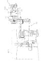
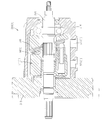
- FIG. 1 is a sectional view of a pump unit according to the first embodiment of the present invention.
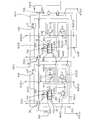
- FIG. 2A is a hydraulic circuit diagram of the pump unit.
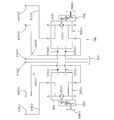
- FIG. 2B is a hydraulic circuit diagram of a motor unit fluidly connected to the pump unit.
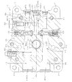
- FIG. 3 is a cross-sectional view taken along line III-III in FIG.
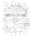
- FIG. 4 is a cross-sectional view taken along line IV-IV in FIG.
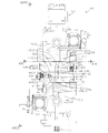
- FIG. 5 is a cross-sectional view taken along line VV in FIG.
- FIG. 6 is an end view taken along the line VI-VI in FIG. 7 is an end view taken along line VII-VII in FIG.
- FIG. 8 is an end view taken along line VIII-VIII in FIG.
- FIG. 9 is an end view taken along line IX-IX in FIG.
- FIG. 10 is a cross-sectional view taken along line XX in FIG.
- FIG. 11 is a cross-sectional view of the vicinity of the first hydraulic motor unit in the working vehicle.
- 12 is a cross-sectional view of the first hydraulic motor unit shown in FIG.
- FIG. 13 is a sectional view of a modification of the first hydraulic motor unit shown in FIG.
- FIG. 14 is a sectional view of a tandem pump unit according to the second embodiment of the present invention.
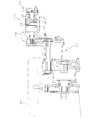
- FIG. 15 is a hydraulic circuit diagram of a working vehicle to which the tandem pump unit is applied.
- 16 is a cross-sectional view taken along line XVI-XVI in FIG. 17 is a cross-sectional view taken along line XVII-XVII in FIG.
- FIG. 18 is a cross-sectional view taken along line XVIII-XVIII in FIG.
- FIG. 19 is an end view taken along line XIX-XIX in FIG. 20 is an end view taken along line XX-XX in FIG.
- FIG. 21 is an end view taken along line XXI-XXI in FIG. 22 is an end view taken along line XXII-XXII in FIG. 23 is a cross-sectional view taken along line XXIII-XXIII in FIG.
- FIG. 24 is a sectional view of the vicinity of the first hydraulic motor unit in the working vehicle.
- 25 is a cross-sectional view of the first hydraulic motor unit shown in FIG.
- FIG. 26 is a cross-sectional view of a modification of the first hydraulic motor unit shown in FIG.
- FIG. 1 shows a cross-sectional view of a pump unit 1 according to the present embodiment.
- the pump unit 1 includes a first hydraulic pump 15 (1), a first end surface 11 a and a first end surface 11 a in which the first hydraulic pump 15 (1) is in direct or indirect sliding contact.
- the first port block 10 (1) having the second end surface 11b opposite to the thickness direction and the first pump space P (1) for housing the first hydraulic pump 15 (1) are formed.
- the first pump case 16 (1), the second hydraulic pump 15 (2), and the second hydraulic pump 15 (2) connected to the first end surface 11a of the 1-port block 10 (1) are directly or indirectly connected.
- a second port block 10 (2) having a first end surface 11a that is in sliding contact with the first end surface 11b and a second end surface 11b opposite to the first end surface 11a in the thickness direction, and a second port that houses the second hydraulic pump 15 (2). So as to form the pump space P (2) And a second pump casing 16 which is connected to the second first end face 11a of the port block 10 (2) (2).
- the pump unit 1 is applied to a work vehicle as a member constituting the traveling transmission 500, for example.
- the traveling transmission is a two-pump / two-motor system.
- FIG. 2A shows a hydraulic circuit diagram of the pump unit 1.
- FIG. 2B shows a hydraulic circuit diagram of the first and second motor units 511 (1) and 511 (2) that are fluidly connected to the pump unit 1 to form the traveling transmission 500.
- the first hydraulic pump 15 (1) of the pump unit 1 is a pair of left and right first and second drive wheels 500 (1 ), 500 (2) and the first hydraulic motor 511 (1) that drives one 500 (1) to form a first HST, and the second hydraulic pump 15 (2)
- the second HST is formed in cooperation with the second hydraulic motor 511 (2) that drives the other 500 (2) of the second drive wheels 500 (1) and 500 (2).
- the working vehicle in addition to the pump unit 1, the working vehicle includes an engine 505 serving as a power source of the pump unit 1, and the pair of first and second drive wheels 500.
- (1), 500 (2), and the first hydraulic motor 511 (fluidally connected to the first hydraulic pump 15 (1) via a pair of first hydraulic lines 410 (1) to form the first HST ( 1), and outputs the rotational power of the first hydraulic motor 511 (1) toward the first drive wheel 500 (1), and the second hydraulic pump 15 (2) having the second hydraulic motor 511 (2) fluidly connected via a pair of second hydraulic lines 410 (2) to form the second HST, of the second hydraulic motor 511 (2)
- Rotational power to the second drive A second hydraulic motor unit 510 (2) that outputs to 500 (2), a charge pump 530 that is operatively driven by the engine 505 and acts as a hydraulic oil supply source for the first and second HSTs, And an oil tank 540 that acts as an oil source for the charge pump 530.
- the first port block 10 (1) has a pair of first hydraulic pump hydraulic fluid passages 411 (1) that form part of the pair of first hydraulic lines 410 (1).
- the second port block 10 (2) is formed with a pair of second hydraulic pump hydraulic fluid passages 411 (2) that form part of the pair of second hydraulic lines 410 (2). .
- the first hydraulic pump 15 (1) is in sliding contact with the sliding contact region 11 a ′ of the first end surface 11 a in the first port block 10 (1)
- the second hydraulic pump 10. (2) is in sliding contact with the sliding contact region 11a ′ of the first end face 11a in the second port block 10 (2).
- the sliding contact region 11a ′ is provided with a pair of kidney ports (not shown) communicating with the suction / discharge portions of the corresponding first and second hydraulic pumps 10 (1), 10 (2),
- the hydraulic oil is supplied and discharged between the corresponding hydraulic pumps 10 (1) and 10 (2) and the corresponding hydraulic oil passages 411 (1) and 411 (2) for the corresponding hydraulic pumps via the pair of kidney ports. It has become so.
- the hydraulic pumps 10 (1) and 10 (2) have an end surface having the suction / discharge section as a concave spherical surface, and the sliding contact region
- the outer surface of 11a ' is a convex spherical surface that engages with the concave spherical surface.
- FIG. 3 is a cross-sectional view of the first port block 10 (1) taken along the line III-III in FIG.
- the first port block 10 (1) drives the corresponding first hydraulic pump 10 (1) in addition to the pair of first hydraulic pump hydraulic fluid passages 411 (1).
- the first shaft hole 14 (1) penetrating between the first and second end faces 11a, 11b so that the first pump shaft 17 (1) is inserted, and the pair of pressure oil from the pressure oil source.
- the first charge oil passage 430 (1) is supplied to the first hydraulic pump hydraulic fluid passage 411 (1).
- the pair of first hydraulic pump hydraulic fluid passages 411 (1) are fluidly connected to the first hydraulic pump 15 (1) and at least one end thereof opens to the outer surface to form a pair of first supply / discharge ports. 411P (1) is formed.
- the pair of first pump hydraulic fluid passages 411 (1) are symmetrical with respect to each other with the first axial hole 14 (1) interposed therebetween.
- a pair of parallel portions 415 opened in the first end surface 11a so as to be fluidly connected to the corresponding first hydraulic pump 15 (1) extending in the first plate surface direction X1 of the first port block 10 (1).
- a pair of main openings 416 that extend from the pair of parallel portions 415 to one side in the first plate surface direction X1 and open to the outer surface to form the pair of first supply / discharge ports 411P (1). is doing.
- the first port block 10 (1) includes first to third members extending in the thickness direction so as to connect the peripheral edges of the first and second end faces 11a, 11b. It has fourth side surfaces 12a to 12d.
- the first and second side surfaces 12a and 12b are respectively directed to one side and the other side of the first plate surface direction X1, and the third and fourth side surfaces 12c and 12d are respectively the first plate.
- the second plate surface direction X2 that is orthogonal to the surface direction X1 faces one side and the other side.
- the first supply / discharge port 411P (1) is open to the first side surface 12a.
- the pair of first hydraulic pump hydraulic fluid passages 411 (1) extends from the pair of parallel portions 415 to the opposite side of the first plate surface direction X1 and extends to the second side surface 12b.
- a pair of sub-openings 417 that are open to each other are provided, and the pair of sub-openings 417 are closed by a plug 417a.
- the pair of first hydraulic pump hydraulic fluid passages 411 (1) pass through the first port block 10 (1) in a state along the first plate surface direction X1. It is formed by a pair of perforated first perforations 400a.
- the first charge oil passage 430 (1) has one end opened to the outer surface to form a pressure oil receiving port 430P and the other end branched to form the pair of first hydraulic pressures.
- the pump hydraulic fluid passage 411 (1) is fluidly connected through a pair of check valves 435.
- each of the pair of check valves 435 has a function of a high pressure relief valve.
- the first charge oil passage 430 (1) is formed by the second and third perforations 400b and 400c.
- the second perforations 400b communicate with the pair of first perforations 400a on the side closer to the second side surface 12b than the first axial hole 14 (1).
- Extending along the second plate surface direction X2, and one end portion and the other end portion are opened in the third and fourth side surfaces 12c and 12d, respectively.
- the third perforation 400c has one end opened to the second side surface 12b and the other end fluidly connected to the second perforation 400b.
- the second and third perforations 400b and 400c form a T shape. That is, the third perforation 400c extends along the first plate surface direction X1 between the pair of hydraulic pump hydraulic fluid passages 411 (1), and one end portion opens to the second side surface 12b. The other end is fluidly connected to the second perforation 400b. More specifically, the third perforation 400c passes along the first plate surface direction X1 and the thickness direction of the first port block 10 (1) while passing through the axis of the first axial hole 14 (1). It is located on the virtual plane IP.
- the pair of check valves 435 are inserted from the one end and the other end of the second perforation 400b, respectively, and from the third perforation 400c to the pair of hydraulic oil passages 411 (1) for the first hydraulic pump.
- the pressure oil is allowed to flow in and the reverse flow is prevented.
- the first port block 10 (1) has one end portion that is connected to the first charge oil passage 430 (1) upstream of the pair of check valves 435 in the pressure oil flow direction.
- a first branch oil passage 440 (1) that is connected and has the other end opened to the second end face 11b to form a connection port 440P is formed.
- connection port 440P passes through the axis of the first axial hole 14 (1) and is connected to the first plate surface direction X1 and the first port block 10 (1). It is located on the virtual plane IP along the thickness direction.
- the first branch oil passage 440 (1) is formed by the fourth perforations 400d.
- the fourth perforation 400d has one end fluidly connected to the third perforation 400c and the other end opened to the second end face 11b.
- FIG. 4 is a cross-sectional view of the second port block 10 (2) taken along line IV-IV in FIG.
- the second port block 10 (2) includes the corresponding second hydraulic pump 15 (2) in addition to the pair of second hydraulic pump hydraulic fluid paths 411 (2).
- the second pump shaft 17 (2) that drives the second pump shaft 17 (2) is inserted, and the second axial hole 14 (2) that penetrates between the first and second end faces 11a, 11b, and the pressure oil from the pressure oil source Is supplied to the pair of second hydraulic pump hydraulic fluid passages 411 (2), and the second charge fluid passage 430 (2) in which the pair of check valves 435 are inserted.
- the second port block 10 (2) has the same outer shape as the first port block 10 (1).
- the pair of second hydraulic pump hydraulic fluid passages 411 (2) have the same configuration as the pair of first hydraulic pump hydraulic fluid passages 411 (1), and the second axial hole 14 (2)
- the first axial hole 14 (1) has the same configuration
- the second charge oil passage 430 (2) has the same configuration as the first charge oil passage 430 (1)
- the second branch oil passage 440 (2) has the same configuration as the first branch oil passage 440 (1). Accordingly, in the drawing, the second port block 10 (2) is denoted by the same reference numeral as that in the first port block 10 (1) or the same reference numeral in which the parentheses are changed to “2”.
- the second branch oil passage 440 (2) has the same configuration as the first branch oil passage 440 (1). That is, the connection port 440P of the second branch oil passage 440 (2) also passes through the corresponding axial hole 14 (2) axis, similarly to the connection port 440P of the first branch oil passage 440 (1). It is located on the virtual plane IP along the first plate surface direction and the thickness direction of the port block.
- the first assembly in which the first hydraulic pump 15 (1) and the first pump case 16 (1) are supported on the first end surface 11a of the first port block 10 (1) and the first assembly are provided.
- the pump shafts 17 In a state where the second end surfaces 11b are in contact with each other while the first plate surface directions of the blocks 10 (1) and 10 (2) are made to coincide with each other, the pump shafts 17 ( 1)
- the first and second port blocks 10 (1) 10 (2) Serial connection port 440P each other is to be fluidly connected.
- the pressure oil from a single pressure oil source is supplied to the first and second port blocks 10 (1), 10 (2) Supplying pressure oil to both the first charge oil passage 430 (1) and the second charge oil passage 430 (2) only by supplying the pressure oil reception port 430P in any one of the above. Can do.
- one of the first and second hydraulic pump charge oil passages 430 (1) and 430 (2) (in the present embodiment, the first hydraulic pump charge oil passage). 430 (1)) is closed by the plug 431 (see FIG. 3), and the other charge oil passage (in the present embodiment, the second hydraulic pump charge oil passage 430 (2)).
- the pressure oil receiving port 430P to the charge pump 530, 530 pressure oil can be supplied from the single charge pump to both the charge oil passages 430 (1) and 430 (2). it can.
- the first and second assemblies can be arranged independently. That is, each of the first and second assemblies can be used as a single pump unit arranged independently.
- each of the first and second port blocks 10 (1) and 10 (2) has four corners when viewed along the thickness direction.
- a mounting boss 13 is provided on the front side.
- the first and second hydraulic pumps 15 (1) and 15 (2) are arranged in tandem, the mounting bosses facing each other are fastened via mounting bolts.
- appropriate mounting bolts in a state where the mounting boss 13 is in contact with a fixed portion such as a frame (not shown). To be fixed to the fixing part.
- connection ports 440P of the first and second port blocks 10 (1) and 10 (2) are fluidly connected to each other through a pipe, thereby enabling a single charge pump 530 to be used. Can be supplied to both charge oil passages 430 (1) and 430 (2).
- the pump unit 1 is configured such that the first and second charge oil passages 430 (1) and 430 (2) are provided by a single relief valve 450. It is configured to set both hydraulic pressures, thereby reducing the cost by reducing the number of parts.
- the relief valve 450 is provided only in one of the first and second port blocks 10 (1) and 10 (2) (in the illustrated embodiment, the first port block 10 (1)). And the hydraulic pressures of both the first and second charge oil passages 430 (1) and 430 (2) are set by the relief valve 450.
- the port block on the side where the relief valve 450 is mounted in the illustrated form, the first port block 10 ( In 1)
- a fifth perforation 400e that functions as an installation hole for the relief valve 450 is formed.
- the fifth perforation 400e has one end opened to the third side surface 12c or the fourth side 12d and the other end fluidly connected to the third perforation 400c. It extends along the second plate surface direction X2 on the side closer to the second side surface 12c from the hole 14 (1), and the relief valve 450 extends from the opening end so that the primary side faces the third perforation 400c. It is inserted into the fifth perforation 400e.
- the relief valve 450 is not mounted in order to improve the manufacturing cost by sharing the first and second port blocks 10 (1) and 10 (2) as much as possible.
- one end of the port block on the side corresponds to the upstream side of the check valve 435 in the pressure oil flow direction.
- the fifth perforation 400e that is fluidly connected to the charge oil passage 430 (2) and that has the other end opened on the outer surface is formed.
- the open end of the fifth perforation 400e is closed by a plug 458.
- the pump unit 1 includes a port block (the first port block 10 (1) in the illustrated embodiment) in which the relief oil from the relief valve 450 is mounted and the relief oil 450.
- the port block is guided to the pump space P (1) defined by the corresponding pump case 16 (1), and the relief oil is not mounted on the relief valve 450 (in the form shown, the second port block 10). (2)) and the pump space P (2) defined by the corresponding pump case 16 (2) are also guided.
- FIG. 5 is a cross-sectional view taken along the line VV in FIG. That is, as shown in FIGS. 3 to 5, the pump unit 1 supplies the relief oil from the relief valve 450 to the first port block 10 (1) to which the relief valve 450 is attached and the corresponding one of the first port block 10 (1).
- a second relief drain oil passage 460 (2) for guiding the second pump space P (2) formed by the port block 10 (2) and the corresponding second pump case 16 (2). Yes.
- the first relief drain oil passage 460 (1) has one end fluidly connected to the secondary side of the relief valve 450 and the other end opened to the first end face 11a.
- the first port block 10 (1) is formed to be fluidly connected to the first pump space P (1).
- the other end of the first relief drain oil passage 460 (1) is opened to the first end face 11a in a region other than the corresponding sliding contact region 11a ′.
- FIG. 6 shows an end view of the second pump case 16 (2) along the line VI-VI in FIG.
- the second relief drain oil passage 460 (2) has one end fluidly connected to the secondary side of the relief valve 450 and the other end connected to the second end face 11b.
- a downstream portion 462 formed in the second port block 10 (2) so as to open to the first end face 11a and be fluidly connected to the second pump space P (2).
- the other end of the downstream portion 462 is opened to the first end surface 11a in a region other than the corresponding sliding contact region 11a ′.
- the first relief drain oil passage 460 (1) and the second relief drain oil passage 460 (2) have a sixth perforation 400f provided in the first port block 10 (1) and the second port block 10 ( And 7th perforation 400g provided in 2).
- the sixth perforation 400f has one end and the other end opened to the first and second end surfaces 11a and 11b in a state of passing through the fifth perforation 400e, respectively.
- the first port block 10 (1) is provided with the relief valve 450 attached thereto.
- the seventh perforation 400g has one end opened to the second end surface 11b and fluidly connected to the other end of the sixth perforation 400f.
- the relief valve 450 is not mounted on the second port block 10 (2) so as to open to the first end surface 11a and fluidly connect to the second pump space P (2).
- a portion of the sixth perforation 400f located closer to the first end face 11a than the fifth perforation 400e forms the first relief drain oil passage 460 (1).
- a portion of the sixth perforation 400f that is closer to the second end surface 11b than the fifth perforation 400e forms the upstream portion 461, and the seventh perforation 400g forms the downstream portion 462. Yes.
- At least one of the first port block 10 (1) and the first pump case 16 (1) is formed by the first pump space.
- a first pump-side drain port 470 (1) that opens P (1) to the outside is formed, and at least one of the second port block 10 (2) and the second pump case 16 (2) is formed by both.
- a second pump-side drain port 470 (2) that opens the second pump space P (2) to the outside is formed.
- the first pump side drain port 470 (1) is formed in the first pump case 16 (1), and the second pump side drain port 470 (2). Is formed in the second pump case 16 (2).
- the relief valve 450 is attached to only one of the first and second port blocks 10 (1) and 10 (2), and the relief valve is installed.
- Relief oil from 450 is guided to both the first and second pump spaces P (1) and P (2), and the first and second pump spaces P (1) and P (2) are stored.
- Oil is configured to be discharged to the outside through the first and second pump-side drain ports 470 (1) and 470 (2), whereby the first and second pumps are provided without any additional parts.
- the stored oil in the two-pump spaces P (1) and P (2) can be circulated efficiently, so that an increase in the temperature of the stored oil can be effectively suppressed.
- the first through hole 475 (1) has one end opened to the first end surface 11a and fluidly connected to the first pump space P (1), and the other end opened to the second end surface 11b. Further, the first port block 10 (1) is formed.
- the second through hole 475 (2) has one end opened to the first end surface 11a and fluidly connected to the second pump space P (2), and the other end opened to the second end surface 11b.
- the second port block 10 (2) is formed to be fluidly connected to the first through hole 475 (1).
- each of the first and second port blocks 10 (1) and 10 (2) has a corresponding pair of hydraulic oil passages 411 (1 ), A bypass valve 480 for selectively communicating or blocking between 411 (2) is provided.
- each of the first and second port blocks 10 (1) and 10 (2) has a corresponding first and second axial hole 14 (1),
- An eighth perforation 400h extending in the second plate surface direction X2 is formed on the side closer to the first side surface 12a than 14 (2).
- the eighth perforation 400h communicates between the corresponding pair of hydraulic oil passages 411 (1) and 411 (2) with one end opened to one of the third or fourth side surfaces 12c and 12d. ing.
- the bypass valve 480 is inserted from the one end of the eighth perforation 400h and selectively fluidly connects between the pair of hydraulic oil passages 411 (1) and 411 (2) based on an external operation. Cut off.
- bypass valve 480 By arranging the bypass valve 480 on the opposite side of the check valve 435 and the relief valve 480 across the axial hole 14 (1), 14 (2) with respect to the second plate surface direction X2, It becomes possible to arrange the bypass valve 480 without difficulty.
- one end of the first pump shaft 17 (1) extends outward from the first pump space P (1).
- the first pump case 16 (1) and the first port block 10 (1) are supported so as to be rotatable about an axis, and the one end of the first pump shaft 17 (1) Rotational power is input.
- the second pump shaft 17 (2) is coaxially connected to the first pump shaft 17 (1) and connected to the first pump shaft 17 (1) so as not to rotate relative to the second pump case 16 ( 2) and the second port block 10 (2) are rotatably supported about the axis.
- the charge pump 530 is driven by the rotational power from the second pump shaft 17 (2). That is, the second pump shaft 17 (2) has one end connected to the other end of the first pump shaft 17 (1) in a relatively non-rotatable manner and outputs rotational power from the other end to the charge pump 530. is doing.
- the charge pump 530 can take various forms, but in the present embodiment, it is a gear pump.
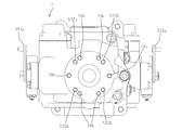
- FIG. 7 shows an end view along the line VII-VII in FIG.
- the charge pump 530 includes a charge pump case 531 connected to the pump unit 1, a charge pump case 531 supported by the second pump shaft 17 (2 ) And a driven shaft 536 supported by the charge pump case 531 in a state parallel to the drive shaft 535, and a non-rotatably supported by the drive shaft 535.
- a suction port 532b and a discharge port 532c are opened in the peripheral wall of the charge pump case 531.
- the suction port 532b is connected to the oil tank 540 via a pipe.
- the discharge port 530c is connected to the pressure oil receiving port 430P via a pipe.
- a line filter and an oil cooler are inserted in the piping connecting the discharge port 530c and the pressure oil receiving port 430P (see FIG. 2A).
- the charge pump case 531 includes a case main body 532 connected to the corresponding second pump case 16 (2), and a lid member 533 connected to the case main body 532. Contains.
- the case main body 532 is detachably connected to an end surface of the second pump case 16 (2) via a fastening member 532 a such as a bolt, and the lid member 533 is connected to the case main body 532.
- a fastening member 533a such as a bolt
- the pump unit 1 As shown in FIG. 1, the pump unit 1 according to the present embodiment is supported by a fixing member 503 such as a vehicle frame via the first pump case 16 (1).
- FIGS. 8 and 9 are end views taken along lines VIII-VIII and IX-IX in FIG. 1, respectively.
- a pedestal member 18 is connected to an end surface of the first pump case 16 (1) via a fastening member 19a such as a bolt, and the pump unit 1 is The pedestal member 18 is fixed to the fixing member 503 via a fastening member 504 such as a bolt while being placed on the fixing member 503.
- the first and second pump cases 16 (1) and 16 (2) have the same configuration in order to achieve common parts. Accordingly, as shown in FIGS. 8 and 9, the fastening holes 532 b for the charge pump case 531 and the base member 18 are formed on the end surfaces of the first and second pump cases 16 (1) and 16 (2). The fastening hole 19b is formed.
- the first and second hydraulic pumps 15 (1) and 15 (2) have the same configuration with respect to each other, and the volumes are individually changed.
- the variable volume type is obtained.
- the pump unit 1 further includes a pair of volume adjusting mechanisms 30 for changing the volumes of the first and second hydraulic pumps 15 (1) and 15 (2), respectively. It has.
- FIG. 10 shows a cross-sectional view along the line XX in FIG.
- the volume adjusting mechanism 30 is tilted about a swing reference axis (not shown) orthogonal to the corresponding pump shafts 17 (1), 17 (2), thereby correspondingly.
- a movable swash plate 31 for changing the volume of the hydraulic pumps 15 (1) and 15 (2) is provided.
- the movable swash plate 31 is tilted using the action of hydraulic pressure.
- the pump unit includes a pair of hydraulic pressures that respectively tilt the movable swash plate 31 for the first and second hydraulic pumps 15 (1) and 15 (2).
- a servo mechanism 35 is provided.
- the hydraulic servo mechanism 35 is accommodated in the cylinder 351 so as to reciprocate so as to separate the internal space of the cylinder 351 into a normal rotation chamber 351a and a reverse rotation chamber 351b.
- a piston 352 a supply line 356 for supplying pressure oil from a pressure oil supply source, a discharge line 357 for guiding the pressure oil to an oil sump, and a normal rotation fluidly connected to the normal rotation chamber and the reverse rotation chamber, respectively.
- a switching valve 353 having the supply line 356 and the discharge line 357 fluidly connected to the primary side and the forward rotation line 358 and the reverse line 359 fluidly connected to the secondary side. is doing.
- the switching valve 353 fluidly connects the supply line 356 and the holding position for closing the forward rotation line 358 and the reverse rotation line 359 to the forward rotation line 358 through the externally operated input arm 353a and discharges the discharge valve 353.
- a forward rotation position where the line 357 is fluidly connected to the reverse rotation line 359 and a reverse rotation position where the supply line 356 is fluidly connected to the reverse rotation line 359 and the discharge line 357 is fluidly connected to the forward rotation line 358 are selectively taken. obtain.
- the input arm 353a is operatively connected to a main speed change operation member such as an operation lever provided in the work vehicle via a link mechanism (not shown).
- the piston 352 moves in the forward direction along the axial direction in response to the supply of pressure oil to the forward rotation chamber 351a, and in the reverse direction along the axial direction in response to the supply of pressure oil to the reverse rotation chamber 351b.
- the piston 352 tilts the movable swash plate 31 in the forward direction around the swing reference axis in accordance with the movement in the forward direction along the axial direction, and moves in the reverse direction along the axial direction.
- the movable swash plate 31 is operatively connected to the movable swash plate 31 so that the movable swash plate 31 is tilted in the reverse direction around the swing reference axis.
- the supply line 356 is upstream of the pair of check valves 435 in the pressure oil flow direction in the corresponding charge oil passages 430 (1) and 430 (2). Is fluidly connected to a portion located at a position where the pressure oil set by the relief valve 450 is received. According to such a configuration, it is possible to reduce the cost by simplifying the pressure oil supply structure for the hydraulic servo mechanism 35.
- the supply line 356 includes a port block side supply oil passage 356a formed in each of the first and second port blocks 10 (1) and 10 (2), and the first and second port blocks 10 (1) and 10 (2). 1 and the 2nd pump case 16 (1) and the pump case side supply oil path 356b formed in each of 16 (2).
- the port block-side supply oil passage 356a has a pair of check valves in the charge oil passages 430 (1) and 430 (2) corresponding to one end. The other end portion is opened to the first end surface 11a.
- the pump case side supply oil passage 356b is configured so that one end thereof is fluidly connected to the port block side supply oil passage 356a. The other end is fluidly connected to the primary side of the switching valve 353.
- the working vehicle includes the first hydraulic motor 511 (1) that cooperates with the first hydraulic pump 15 (1) to form the first HST.
- the second hydraulic motor unit 510 (2) has the same configuration as the first hydraulic motor unit 510 (1). Accordingly, in the drawing, for the second hydraulic motor unit 510 (2), the same constituent members as those in the first hydraulic motor unit 510 (1) are given the same reference numerals or the same reference numerals in which the parentheses are changed to “2”. It is attached.
- FIG. 11 is a sectional view of the vicinity of the first hydraulic motor unit 510 (1).
- FIG. 12 shows a sectional view of the first hydraulic motor unit 510 (1).
- the first hydraulic motor unit 510 (1) includes a pair of first motors that open the first motor space M (1) that houses the first hydraulic motor 511 (1) to the outside.
- a motor side drain port 570 (1) is provided.
- the second hydraulic motor unit 510 (2) has a pair of second motor side drain ports 570 (2) that open the second motor space M (2) that houses the second hydraulic motor 511 (2) to the outside. ) Is provided.
- one of the pair of first motor side drain ports 570 (1) is fluidly connected to the first pump side drain port 470 (1) and the pair of first motors.
- the other side drain port 570 (1) is fluidly connected to the oil tank 540, and one of the pair of second motor side drain ports 570 (2) is fluidly connected to the second pump side drain port 470 (2).
- the other of the pair of second motor side drain ports 570 (2) connected is fluidly connected to the oil tank 540.
- the first and second pump spaces P (1), P (2), the first and second motor spaces M (1), M (2), and the like without any additional member.
- the stored oil can be actively circulated between the oil tanks 540, and the first and second hydraulic pumps 15 (1) and 15 (2) and the first and second hydraulic motors 511 (1), The temperature increase of 511 (2) can be effectively prevented.
- Each of the first and second hydraulic motor units 510 (1) and 510 (2) includes a port block 513 and the hydraulic motors 511 (1) (511 (2)) that are in sliding contact with the port block 513.
- a motor case 514 coupled to the port block 513 so as to form the motor space M (1) (M (2)) that accommodates the hydraulic motor 511 (1) (511 (2));
- a motor shaft 515 is rotatably supported by the port block 513 and the motor case 514 in a state where the motor 511 (1) (521 (1)) is supported so as not to be relatively rotatable.
- the motor case 514 is formed with the pair of motor-side drain ports 570 (1) (570 (2)).
- the port block 513 has the same base structure as the first port block 10 (1) and the second port block 10 (2) shown in FIGS. 3 and 4, and the check valve, the relief valve, The bypass valve and the associated oil passage are eliminated.
- the rotating member (cylinder block or piston) of the hydraulic motor 511 (1) (511 (2)) is the same as the rotating member in the first and second hydraulic pumps 15 (1) and 15 (2). The same member is used. Therefore, the total cost can be greatly reduced while using a total of four hydraulic devices because of the two-pump / two-motor system.
- each of the first and second hydraulic motor units 510 (1) and 510 (2) has a fixed volume of the corresponding hydraulic motor 511 (1) (511 (2)). It is a fixed volume type.
- each of the first and second hydraulic motor units 510 (1) and 510 (2) further includes the corresponding hydraulic motors 511 (1) and 511 (2). ) Is fixed to a predetermined volume.
- each of the first and second hydraulic motor units 510 (1) and 510 (2) may be provided with a movable swash plate 517 instead of the fixed swash plate 516. is there. According to such a configuration, it is possible to increase the torque of the traveling output that drives the drive wheels.
- each of the first and second hydraulic motor units 510 (1) and 510 (2) includes a hydraulic servo mechanism that tilts the movable swash plate 517 using the action of hydraulic pressure. 518.
- each of the first and second hydraulic motor units 510 (1), 510 (2) is the first and second hydraulic pumps 15 (1), 15 (2) except for the motor shaft 515. ) Can be used, and the component sharing rate can be further increased.
- the pressure oil supply structure for the hydraulic servo mechanism 518 is the same as the pressure oil supply structure in the first and second hydraulic pumps 15 (1) and 15 (2). That is, the pressure oil supply structure for the hydraulic servo mechanism 518 includes a motor case side supply oil passage 519b and a port block side supply oil passage 519a, and the pressure received from the supply port 520 opened on the circumferential wall surface of the port block 513. The oil is supplied to the hydraulic servo mechanism 518 through the oil passages 519a and 519b. A pipe branched from the discharge port 530c of the charge pump 531 is connected to the supply port 520.
- the movable swash plate 517 of the first and second hydraulic motor units 510 (1) and 510 (2) is operated in a synchronized state with each other by a single auxiliary transmission operation member. . That is, the movable swash plate 517 of the first hydraulic motor unit 510 (1) and the movable swash plate 517 of the second hydraulic motor unit 510 (2) are connected to the single auxiliary transmission operation member via a link mechanism. Operated linked.
- the movable swash plate 517 in the first and second hydraulic motor units 510 (1) and 510 (2) is operated in a synchronized state with each other by a single auxiliary transmission operation member.
- An input arm provided in the servo mechanism 518 is operatively connected to the single auxiliary transmission operation member via a link mechanism.
- the movable swash plate 517 in the first and second hydraulic motor units 510 (1) and 510 (2) is configured so that the tilt angle is stepped in two or three steps.
- the working vehicle includes drive wheels 501 corresponding to the first and second hydraulic motor units 510 (1) and 510 (2), as shown in FIGS. 2B and 11.
- a pair of reduction gear units 550 interposed between the pair of brakes 502 and a pair of brakes capable of applying a braking force to the motor shafts 515 of the first and second hydraulic motor units 510 (1) and 510 (2), respectively.
- a unit 560 is provided.
- the rotor unit of the brake unit 560 is fixed to the inner end of each of the motor shafts 515.
- the port block 513 has the same base structure as the first and second port blocks 10 (1) and 10 (2).
- Bolts are connected to the outer surface around the input portion of the reduction gear unit 550.
- FIG. 14 shows a cross-sectional view of the pump unit 100 according to the present embodiment.
- the pump unit 100 is a tandem type in which first and second hydraulic pumps are arranged in series on the same straight line.
- the pump unit 100 includes a port block 110 in which a plurality of oil passages are formed and a first hydraulic pump 15 (1) that is in sliding contact with the first pump side end surface 110 (1) on one side in the thickness direction of the port block 110. ), A second hydraulic pump 15 (2) slidably in contact with the second pump side end face 110 (2) on the other side in the thickness direction of the pump unit, and a first pump space for housing the first hydraulic pump 15 (1) A first pump case 16 (1) connected to the port block 110 and a second pump space P (2) for accommodating the second hydraulic pump 15 (2) are formed so as to form P (1). In this way, a second pump case 16 (2) connected to the port block 110 is provided.
- the pump unit 100 is applied to a work vehicle as a member constituting the traveling transmission 500, for example.
- FIG. 15 is a hydraulic circuit diagram of a traveling transmission 500 to which the pump unit 100 is applied.
- the first hydraulic pump 15 (1) of the pump unit 100 is one of a pair of left and right first and second drive wheels 500 (1) and 500 (2) 500.
- the first hydraulic motor 511 (1) that drives (1) cooperates to form a first HST
- the second hydraulic pump 15 (2) includes the pair of first and second drive wheels 500 (1)
- the second HST is formed in cooperation with the second hydraulic motor 511 (2) that drives the other 500 (2) of the 500 (2).
- the working vehicle in addition to the pump unit 100, includes an engine 505 serving as a power source of the pump unit 100, and the pair of first and second drive wheels 500 (1). , 500 (2) and the first hydraulic motor 511 (1) that is fluidly connected to the first hydraulic pump 15 (1) via a pair of first hydraulic lines 410 (1) to form the first HST.
- the second hydraulic motor 511 (2) is fluidly connected to each other via a pair of second hydraulic lines 410 (2) to form the second HST, and the rotational power of the second hydraulic motor 511 (2) is supplied.
- Said second drive wheel A second hydraulic motor unit 510 (2) that outputs toward 00 (2), a charge pump 530 that is operatively driven by the engine 505 and that serves as a hydraulic oil supply source for the first and second HSTs, And an oil tank 540 that acts as an oil source for the charge pump 530.
- the port block 110 includes a pair of first hydraulic pump hydraulic fluid passages 411 (1) forming a part of the pair of first hydraulic lines 410 (1), and the pair of first hydraulic lines 410 (1).
- a pair of second hydraulic pump hydraulic fluid passages 411 (2) forming part of the second hydraulic line 410 (2) is formed.
- the port block 110 includes the first pump side end face 110 (1) including a sliding contact area 110a (1) with which the first hydraulic pump 15 (1) is slidably contacted. And a first port block 111 to which the first pump case 15 (1) is coupled, and a sliding contact area 110a (2) in which the second hydraulic pump 15 (2) is in sliding contact. And a second port block 112 having a side end face 110 (2) to which the second pump case 16 (2) is connected.
- Each of the sliding contact areas 110a (1) and 110a (2) has a pair of kidney ports (see FIG. 5) leading to the suction / discharge portions of the corresponding first and second hydraulic pumps 15 (1) and 15 (2).
- the hydraulic oil is supplied and discharged between the corresponding hydraulic pump and the corresponding hydraulic oil passage for the hydraulic pump via the pair of kidney ports.
- the hydraulic pumps 15 (1), 15 (2) have a concave spherical surface at the end surface having the suction / discharge portions, and the sliding contact region
- the outer surface is a convex spherical surface that engages with the concave spherical surface.
- the first port block 111 includes a first end surface 111 (1) forming the first pump side end surface 110 (1) and a thickness of the first end surface 111 (1). And a second end surface 111 (2) on the opposite side.
- the second port block 112 includes a first end surface 112 (1) forming the second pump side end surface 110 (2) and a second end surface 112 on the opposite side in the thickness direction from the first end surface 112 (1). (2).
- the first and second port blocks 111 and 112 are connected with the second end surfaces 111 (2) and 112 (2) being in contact with each other.
- FIG. 16 is a sectional view of the first port block 111 taken along line XVI-XVI in FIG.
- FIG. 17 is a sectional view of the second port block 112 taken along line XVII-XVII in FIG.
- the pair of first hydraulic pump hydraulic fluid passages 411 (1) are formed in the first port block 111, and the pair of second hydraulic pumps.
- the hydraulic fluid passage 411 (2) is formed in the second port block 112.
- the pair of first hydraulic pump hydraulic fluid passages 411 (1) are fluidly connected to the first hydraulic pump 15 (1) and at least one end thereof is open to the outer surface.
- a pair of first supply / discharge ports 411P (1) is formed.
- the first port block 111 is inserted such that the first pump shaft 17 (1) that drives the corresponding first hydraulic pump 15 (1) is inserted through the first port block 111.
- the pair of first hydraulic pump hydraulic fluid passages 411 (1) are parallel to each other across the axial hole 111a in the first plate surface direction of the first port block 111. And a pair of parallel portions 415 opened in the first end surface 111 (1) so as to be fluidly connected to the first hydraulic pump 15 (1), and the first plate surface from the pair of parallel portions 415 A pair of main openings 416 extending in one direction and opening on the outer surface to form the pair of first supply / discharge ports 411P (1).
- the pair of first hydraulic pump hydraulic fluid passages 411 (1) extend from the pair of parallel portions 415 to the opposite side in the first plate surface direction and open to the outer surface.
- the sub-openings 417 are closed, and the pair of sub-openings 417 are closed by plugs 417a.
- the pair of second hydraulic pump hydraulic fluid passages 411 (2) are fluidly connected to the second hydraulic pump 15 (2) and at least one end thereof is on the outer surface.
- a pair of second supply / discharge ports 411P (2) are formed by opening.
- the second port block 112 is inserted with the second pump shaft 17 (2) for driving the corresponding second hydraulic pump 15 (2).
- An axial hole 112a penetrating between the first and second end faces 112 (1) and 112 (2) is formed.
- the pair of second hydraulic pump hydraulic fluid passages 411 (2) are parallel to each other across the axial hole 112a in the first plate surface direction of the second port block 112. And a pair of parallel portions 425 opened in the first end face 112 (1) so as to be fluidly connected to the second hydraulic pump 15 (2), and the first plate surface from the pair of parallel portions 425.
- a pair of main openings 426 extending in one direction and opening on the outer surface to form the pair of second supply / discharge ports 411P (2).
- the pair of second hydraulic pump hydraulic oil passages 411 (2) extend from the pair of parallel portions 425 to the opposite side in the first plate surface direction and open to the outer surface.
- the sub-openings 427 are closed, and the pair of sub-openings 427 are closed by a plug 427a.
- the port block 100 is further supplied with hydraulic oil from the charge pump 530 acting as a hydraulic oil supply source via a pair of check valves 435.
- a charge oil passage 430 (2) for the second hydraulic pump that guides to 421 is formed.
- the charge oil passages 430 (1) and 430 (2) for the first and second hydraulic pumps are The first and second port blocks 111 and 112 are formed respectively.
- the charge oil passage 430 (1) for the first hydraulic pump has one end open to the outer surface and can form a pressure oil receiving port 430P, and the other end is branched.
- the fluid is connected to the pair of first pump hydraulic fluid passages 411 (1) via the check valve 435, respectively.
- the second hydraulic pump charge oil passage 430 (2) has one end opened to the outer surface to form a pressure oil receiving port 430P and the other end branched.
- the fluid is connected to the pair of second hydraulic fluid passages 411 (2) via the check valve 435, respectively.
- one of the first and second hydraulic pump charge oil passages 430 (1) and 430 (2) (in the present embodiment, the first hydraulic pump charge oil passage 430 (1 )) Is closed by a plug 431 (see FIG. 3), and the charge pump 530 is connected to the other charge oil passage (in this embodiment, the second hydraulic pump charge oil passage 430 (2 ))
- the pressure oil receiving port 430P In a state fluidly connected to the pressure oil receiving port 430P, a part of the pressure oil in the other charge oil passage is divided into one charge oil passage.
- each of the first and second port blocks 111 and 112 has the charge oil passages 430 (1) and 430 ( A branch oil passage 440 that is fluidly connected to 2) and has the other end opened to the second end faces 111 (2) and 112 (2) to form a connection port 440P is provided.
- connection port 440 ⁇ / b> P is an imaginary surface along the first plate surface direction and the thickness direction of the port blocks 111 and 112 in a state of passing through the axis lines of the axial holes 111 a and 112 a.
- the port blocks 111 and 112 are positioned on the IP so that the second end surfaces 111 (2) and 112 (2) of the first and second port blocks 111 and 112 are in contact with each other.
- the pump unit 100 further includes a single hydraulic pressure for setting the hydraulic pressures of the first and second hydraulic pump charge oil passages 430 (1) and 430 (2).
- the port block 110 includes the first and second port blocks 111 and 112.
- the single relief valve 450 is attached to one of the first and second port blocks 111 and 112 (the first port block 111 in the present embodiment).
- FIG. 18 is a cross-sectional view taken along line XVIII-XVIII in FIG.
- FIG. 19 is an end view taken along line XIX-XIX in FIG.
- one end of one of the first and second port blocks 111 and 112 is pressurized oil from the check valve 435.
- a perforation 459 that is fluidly connected to the corresponding charge oil passage 430 (1) on the upstream side in the flow direction and that has the other end opened on the outer surface is formed.
- the relief valve 450 is inserted into the perforation 459 from the other end so that the primary side faces the charge oil passage 430 (1).
- the first and second port blocks 111 and 112 have a common base structure. That is, the first and second port blocks 111 and 112 have substantially the same configuration except that one (the first port block 111 in the present embodiment) is provided with the check valve 435. It is supposed to be. Specifically, as shown in FIGS. 17 and 18, one end of the port block on the side where the relief valve 450 is not mounted (the second port block 112 in the present embodiment) is pressurized by the check valve 435. A perforation 459 that is fluidly connected to the corresponding charge oil passage 430 (2) on the upstream side in the oil flow direction and that has the other end opened to the outer surface is formed. In the port block 12 on the side where the relief valve 450 is not mounted, the other end of the perforation 459 is closed by a plug 458.
- the first and second port blocks 111 and 112 are provided with mounting bosses 13 at the four corners when viewed along the thickness direction.
- versatility of the first and second port blocks 111 and 112 can be improved. That is, by providing the mounting boss 13, it is possible to cope with a specification mode in which each of the first and second port blocks 111 and 112 is independently attached to the fixing member.
- the first relief drain oil passage 460 (1) has a pump space (in the present embodiment) having one end fluidly connected to the secondary side of the relief valve 450 and the other end corresponding thereto. Is formed in the port block (the first port block 111 in the present embodiment) on the side where the relief valve 450 is mounted so as to open to the first pump space P (1)). Specifically, the other end of the first relief drain oil passage 460 (1) is opened to the first end surface 111 (1) in a region other than the corresponding sliding contact region 110a (1).
- the second relief drain oil passage 460 (2) has one end fluidly connected to the secondary side of the relief valve 450 and the other end of the second end face 111 (2).
- the port block on the side where the relief valve 450 is not mounted so as to be fluidly connected to the pump space formed by the port block on the side where the valve 450 is not mounted (second pump space P (2) in the present embodiment).
- the embodiment includes a downstream portion 462 formed in the second port block 112). Specifically, the downstream portion 462 is opened in the second end surface 112 (2) so that one end thereof is fluidly connected to the upstream portion, and the sliding contact region 110a (2) to which the other end corresponds.
- the first end face 112 (1) is opened in the other area.
- each of the first and second port blocks 111 and 112 has a corresponding pair of hydraulic fluid passages 411 (1) (411 ( A bypass valve 480 is provided for selectively communicating or blocking between 2)).
- the pump unit 100 includes a first pump-side drain port 470 (1) that opens the first pump space P (1) to the outside, and the second pump space P (2).
- a second pump side drain port 470 (2) that opens to the outside is provided.
- the first pump side drain port 470 (1) is formed in at least one of the port block 110 and the first pump case 16 (1)
- the second pump side drain port 470 (2) is formed in the port block 110 and It is formed on at least one of the second pump case 16 (2).
- the first pump side drain port 470 (1) is formed in the first pump case 16 (1), and the second pump side drain port 470 (2). Is formed in the second pump case 16 (2).
- the pump unit 100 includes the first and second pump spaces P (1) and P (2) formed on one side and the other side of the port block 110.
- the first HST including the first hydraulic pump 15 (1) for supplying hydraulic oil to the first HST The hydraulic pressure of the second hydraulic pump charge oil passage 430 (2) for supplying hydraulic oil to the second HST including the hydraulic pump charge oil passage 430 (1) and the second hydraulic pump 15 (2) is simply reduced. It is configured to be set by one relief valve 450, thereby reducing the cost by sharing parts.
- the pump unit 100 attaches the single relief valve 450 to the port block 110 located between the first and second hydraulic pumps 15 (1) and 15 (2) in the axial direction.
- Relief oil from the relief valve 450 is guided to the first and second pump spaces P (1) and P (2), respectively, and the first and second pump spaces P (1) and P (2).
- the first and second pump-side drain ports 470 (1), 470 (2) thereby allowing the first oil to be discharged to the outside without any additional parts.
- the stored oil in 2nd pump space P (1) and P (2) can be circulated efficiently, and, thereby, the temperature rise of the said stored oil can be suppressed effectively.
- the port block 110 is formed with a through hole for fluidly connecting the first and second pump spaces P (1) and P (2).
- the port block 110 includes the first and second port blocks 111 and 112. Accordingly, as shown in FIGS. 16 and 17, the through hole includes a first through hole 111 b formed in the first port block 111 and a second through hole 112 b formed in the second port block 112. Contains.
- the first through-hole 111b opens at the first end surface 111 (1) so that one end thereof is fluidly connected to the first pump space P (1) and the other end is the second end surface 111 (2). Is open.
- the second through-hole 112b opens at the first end surface 112 (1) so that one end thereof is fluidly connected to the second pump space P (2), and the other end is fluidly connected to the first through-hole 111b.
- An opening is formed in the second end face 112 (2) so as to be connected.
- one end of the first pump shaft 17 (1) extends outward from the first pump space P (1).
- the first pump case 16 (1) and the first port block 111 are supported so as to be rotatable about the axis, and the rotational power from the engine 505 is received at one end of the first pump shaft 17 (1). Input is allowed.
- the second pump shaft 17 (2) is coaxially connected to the first pump shaft 17 (1) and connected to the first pump shaft 17 (1) so as not to rotate relative to the second pump case 16 ( 2) and the second port block 112 are rotatably supported around the axis.
- the charge pump 530 is driven by the rotational power from the second pump shaft 16 (2). That is, the second pump shaft 16 (2) has one end connected to the other end of the first pump shaft 16 (1) in a relatively non-rotatable manner and outputs rotational power from the other end to the charge pump 530. is doing.
- the charge pump 530 can take various forms, but in the present embodiment, it is a gear pump.
- FIG. 20 shows an end view along the line XX-XX in FIG.
- the charge pump 530 includes a charge pump case 531 connected to the pump unit 100, and is supported by the charge pump case 531 and is axially connected to the second pump shaft 27.
- a drive shaft 535 coupled so as not to rotate relative to each other, a driven shaft 536 supported by the charge pump case 531 in a state parallel to the drive shaft 535, and a state supported so as not to be relatively rotatable by the drive shaft 535.
- the charge pump case 531 includes a case main body 532 connected to the corresponding second pump case 16 (2) and a lid member 533 connected to the case main body 532. Contains.
- the case main body 532 is detachably connected to the end surface of the second pump case 16 (2) via a fastening member 532 a such as a bolt, and the lid member 533 is connected to the case main body 532.
- a fastening member 533a such as a bolt
- the pump unit 100 according to the present embodiment is supported by a fixing member 503 such as a vehicle frame via the first pump case 16 (1) as shown in FIG.
- FIGS. 14 and 21 are end views taken along lines XXI-XXI and XXII-XXII in FIG. 14, respectively.
- a pedestal member 18 is connected to an end surface of the first pump case 16 via a fastening member 19 a such as a bolt, and the pump unit 100 is connected to the pedestal member 18.
- a fastening member 19 a such as a bolt
- the pump unit 100 is connected to the pedestal member 18.
- the first and second pump cases 16 (1) and 16 (2) have the same configuration in order to achieve common parts. Accordingly, as shown in FIGS. 21 and 22, the fastening holes 532b for the charge pump case 531 and the pedestal member 18 are formed on the end surfaces of the first and second pump cases 16 (1) and 16 (2). The fastening hole 19b is formed.
- the pump unit 100 is a variable displacement type that can individually change the volumes of the first and second hydraulic pumps 15 (1) and 15 (2). Specifically, as shown in FIGS. 14 and 15, the pump unit 100 further includes a pair of volume adjusting mechanisms 30 for changing the volumes of the first and second hydraulic pumps 15 (1) and 15 (2), respectively. It has.
- FIG. 23 is a sectional view taken along line XXIII-XXIII in FIG.
- the volume adjusting mechanism 30 is tilted about a swing reference axis (not shown) orthogonal to the corresponding pump shafts 17 (1), 17 (2), thereby correspondingly.
- a movable swash plate 31 for changing the volume of the hydraulic pump is provided.
- the movable swash plate 31 is tilted using the action of hydraulic pressure.
- the pump unit 100 includes a pair of tilting the movable swash plates 31 for the first and second hydraulic pumps 15 (1) and 15 (2).
- a hydraulic servo mechanism 35 is provided.
- the hydraulic servo mechanism is accommodated in the cylinder 351 so as to reciprocate so as to separate the internal space of the cylinder 351 into a normal rotation chamber 351a and a reverse rotation chamber 351b in a liquid-tight manner.
- Piston 352 supply line 356 for supplying pressure oil from a pressure oil supply source, discharge line 357 for guiding the pressure oil to the oil sump, and normal rotation lines fluidly connected to the normal rotation chamber and the reverse rotation chamber, respectively.
- 358 and a reverse line 359, and a switching valve 353 in which the supply line 356 and the discharge line 357 are fluidly connected to the primary side and the forward line 358 and the reverse line 359 are fluidly connected to the secondary side. ing.
- the switching valve 353 fluidly connects the supply line 356 and the holding position for closing the forward rotation line 358 and the reverse rotation line 359 to the forward rotation line 358 through the externally operated input arm 353a and discharges the discharge valve 353.
- a forward rotation position where the line 357 is fluidly connected to the reverse rotation line 359 and a reverse rotation position where the supply line 356 is fluidly connected to the reverse rotation line 359 and the discharge line 357 is fluidly connected to the forward rotation line 358 are selectively taken. obtain.
- the input arm 353a is operatively connected to a main speed change operation member such as an operation lever provided in the work vehicle via a link mechanism (not shown).
- the piston 352 moves in the forward direction along the axial direction in response to the supply of pressure oil to the forward rotation chamber 351a, and in the reverse direction along the axial direction in response to the supply of pressure oil to the reverse rotation chamber 351b.
- the piston tilts the movable swash plate 31 in the forward direction around the swing reference axis and moves in the reverse direction along the axial direction in accordance with the movement in the forward direction along the axial direction. Accordingly, the movable swash plate 31 is operatively connected to the movable swash plate 31 so that the movable swash plate 31 is tilted in the reverse direction around the swing reference axis.
- the supply line 356 is upstream of the pair of check valves 435 in the pressure oil flow direction in the corresponding charge oil passages 430 (1) and 430 (2). Is fluidly connected to a portion located at a position where the pressure oil set by the relief valve 450 is received. According to such a configuration, it is possible to reduce the cost by simplifying the pressure oil supply structure for the hydraulic servo mechanism 35.
- the supply line 356 includes a port block-side supply oil passage 356a formed in each of the first and second port blocks 111 and 112, and the first and second pump cases. 16 (1), 16 (2), and a pump case side supply oil passage 356b.
- the port block-side supply oil passage 356a has the pair of check valves in the charge oil passages 430 (1) and 430 (2) corresponding to one end.
- the other end portion is opened to the second end surfaces 111 (2) and 112 (2).
- the pump case side supply oil passage 356a is in contact with the port blocks 111 and 112 so that one end thereof is fluidly connected to the port block side supply oil passage 356a.
- the contact portion is open and the other end is fluidly connected to the primary side of the switching valve 353.
- the working vehicle includes the first hydraulic motor unit 510 (1) including the first hydraulic motor 511 that cooperates with the first hydraulic pump 15 (1) to form the first HST. And the second hydraulic motor unit 510 (2) including the second hydraulic motor 511 (2) that forms the second HST in cooperation with the second hydraulic pump 15 (2).
- the second hydraulic motor unit 510 (2) has the same configuration as the first hydraulic motor unit 510 (1). Therefore, the description of the first hydraulic motor unit 510 (1) below applies also to the second hydraulic motor unit 510 (2).
- FIG. 24 is a sectional view of the vicinity of the first hydraulic motor unit 510 (1).
- FIG. 25 is a sectional view of the first hydraulic motor unit 510 (1).
- the first hydraulic motor unit 510 (1) includes a pair of first motors that open the first motor space M (1) that houses the first hydraulic motor 511 (1) to the outside.
- a motor side drain port 570 (1) is provided.
- the second hydraulic motor unit 510 (2) has a pair of second motor side drain ports 570 (2) that open the second motor space M (2) that houses the second hydraulic motor 511 (2) to the outside. ) Is provided.
- one of the pair of first motor side drain ports 570 (1) is fluidly connected to the first pump side drain port 470 (1) and the pair of first motor side drain ports.
- the other of 570 (1) is fluidly connected to the oil tank 540
- one of the pair of second motor side drain ports 570 (2) is fluidly connected to the second pump side drain port 470 (2) and
- the other of the pair of second motor side drain ports 570 (2) is fluidly connected to the oil tank 540.
- the first and second pump spaces P (1), P (2), the first and second motor spaces M (1), M (2), and the like without any additional member.
- the stored oil can be actively circulated between the oil tanks 540, and the first and second hydraulic pumps 15 (1) and 15 (2) and the first and second hydraulic motors 511 (1), The temperature increase of 511 (2) can be effectively prevented.
- Each of the first and second hydraulic motor units 510 (1) and 510 (2) includes a port block 513 and the hydraulic motors 511 (1) (511 (2)) that are in sliding contact with the port block 513.
- a motor case 514 coupled to the port block 513 so as to form the motor space M (1) (M (2)) that accommodates the hydraulic motor 511 (1) (511 (2));
- a motor shaft 515 is rotatably supported by the port block 513 and the motor case 514 in a state where the motors 511 (1) and 511 (2) are supported so as not to rotate relative to each other.
- the motor case 514 is formed with the pair of motor-side drain ports 570 (1) (570 (2)).
- each of the first and second hydraulic motor units 510 (1) and 510 (2) has a fixed volume of the corresponding hydraulic motor 511 (1) (511 (2)). It is a fixed volume type.
- each of the first and second hydraulic motor units 510 (1) and 510 (2) further includes the corresponding hydraulic motors 511 (1) and 511 (2).
- each of the first and second hydraulic motor units 510 (1) and 510 (2) may be provided with a movable swash plate 517 instead of the fixed swash plate 516. is there. In this case, it is possible to increase the torque of the travel output that drives the drive wheels.
- the movable swash plate 517 of the first and second hydraulic motor units 510 (1) and 510 (2) is operated in a synchronized state with each other by a single auxiliary transmission operation member. That is, the movable swash plate 517 of the first hydraulic motor unit 510 (1) and the movable swash plate 517 of the second hydraulic motor unit 510 (2) are connected to the single auxiliary transmission operation member via a link mechanism. Operated linked.
- the working vehicle includes a drive wheel 500 (1) corresponding to the first and second hydraulic motor units 510 (1), 510 (2). 1), a braking force is applied to the pair of reduction gear units 550 interposed between 500 (2) and the motor shafts 515 of the first and second hydraulic motor units 510 (1), 510 (2).
- a pair of brake units 560 that can be added are provided.
- the port block 513 has the same base structure as the first and second port blocks 111 and 112, and the input of the reduction gear unit 550 via the mounting boss 13. Bolts are connected to the outer surface around the part.
Landscapes
- Engineering & Computer Science (AREA)
- Mechanical Engineering (AREA)
- General Engineering & Computer Science (AREA)
- Chemical & Material Sciences (AREA)
- Combustion & Propulsion (AREA)
- Transportation (AREA)
- Details Of Reciprocating Pumps (AREA)
Abstract
Description
前記第1形態に係るポンプユニットは、単一のポートブロックと、前記ポートブロックの厚み方向一方側の第1端面に摺接された第1油圧ポンプと、前記第1油圧ポンプを囲繞するように前記ポートブロックの前記第1端面に連結された第1ポンプケースと、前記ポートブロックの厚み方向他方側の第2端面に摺接された第2油圧ポンプと、前記第2油圧ポンプを囲繞するように前記ポートブロックの前記第2端面に連結された第2ポンプケースとを備えている。
さらに、前記単一のポートブロックは前記第1形態に係るタンデムポンプユニットに専用の部材となり、汎用性に欠ける。
さらに、前記単一のポンプケースは前記第2形態に係るポンプユニットに専用の部材となり、汎用性に欠ける。
特に、前記タンデム構成においては、前記第1及び第2ポートブロックの第2端面同士を当接させた状態で両ポートブロックを連結させることにより、両ポートブロックの前記接続ポート同士が連結されるので、追加部材を備えることなく、前記単一のリリーフ弁による双方のチャージ油路の油圧設定を実現できる。
この場合、前記第1リリーフドレン油路は、一端部が前記リリーフ弁に流体接続され且つ他端部が第1端面に開口して前記一方のポンプ空間に流体接続されるように前記一方のポートブロックに形成される。
一方、前記第2リリーフドレン油路は、一端部が前記リリーフ弁に流体接続され且つ他端部が第2端面に開口するように前記一方のポートブロックに形成された上流側部分と、一端部が前記上流側部分に流体接続されるように第2端面に開口され且つ他端部が第1端面に開口して前記他方のポンプ空間に流体接続されるように前記他方のポートブロックに形成された下流側部分とを含み得る。
前記一方のポートブロック及び対応するポンプケースの少なくとも一方には両者によって形成されるポンプ空間を外部に開くドレンポートが形成され、前記他方のポートブロック及び対応するポンプケースの少なくとも一方には両者によって形成されるポンプ空間を外部に開くドレンポートが形成される。
この場合において、前記第1及び第2ポートブロックの各々には、前記軸線孔を挟んで互いに対して対称な状態で前記第1板面方向に延び、一端部及び他端部がそれぞれ前記第1及び第2側面に開口された一対の第1穿孔と、前記軸線孔より前記第2側面に近接する側において前記一対の第1穿孔の間を連通するように前記第2板面方向に沿って延び、一端部及び他端部がそれぞれ前記第3及び第4側面に開口された第2穿孔と、一端部が前記第2側面に開口し且つ他端部が前記第2穿孔に流体接続された第3穿孔と、一端部が前記第3穿孔に流体接続され且つ他端部が前記第2端面に開口されて前記分岐油路を形成する第4穿孔とが形成される。
前記一対の第1穿孔は他端部がプラグによって閉塞されることで一端部が前記給排ポートとして作用する前記一対の作動油路を形成する。
前記第2穿孔の一端部及び他端部からそれぞれ前記チェック弁が挿入されることで前記第3穿孔の一端部が前記圧油受入ポートとして作用した状態で前記第2穿孔及び前記第3穿孔が前記チャージ油路を形成する。
さらに、前記第1及び第2ポートブロックのうち、前記リリーフ弁が装着される一方のポートブロックには、一端部が前記第3側面に開口し且つ他端部が前記第3穿孔に流体接続するように前記軸線孔より前記第2側面に近接する側において前記第2板面方向に沿って延びた第5穿孔であって、前記一端部から前記リリーフ弁が挿入されるリリーフ弁挿入孔を形成する第5穿孔と、前記第5穿孔を貫通した状態で一端部及び他端部が前記第1及び第2端面に開口された第6穿孔とが設けられる一方で、前記リリーフ弁が装着されない他方のポートブロックには、前記第6穿孔の他端部と流体接続するように一端部が前記第2端面に開口され且つ他端部が前記第1端面に開口された第7穿孔が設けられる。
前記第6穿孔のうち前記第5穿孔よりも第1端面寄りに位置する部分が前記第1リリーフドレン油路を形成し、前記第6穿孔のうち前記第5穿孔よりも第2端面寄りに位置する部分及び前記第7穿孔が前記第2リリーフドレン油路を形成する。
前記第8穿孔は、一端部が前記第3又は第4側面の一方に開口された状態で前記一対の作動油路の双方に流体接続され、前記第8穿孔の前記一端部から挿入されたバイパス弁によって、前記一対の作動油路の間が選択的に流体接続又は遮断される。
以下、本発明に係るポンプユニットの好ましい実施の形態について添付図面を参照しつつ説明する。
図1に示すように、前記ポンプユニット1は、第1油圧ポンプ15(1)と、前記第1油圧ポンプ15(1)が直接又は間接的に摺接する第1端面11a及び前記第1端面11aとは厚み方向反対側の第2端面11bを有する第1ポートブロック10(1)と、前記第1油圧ポンプ15(1)を収容する第1ポンプ空間P(1)を形成するように前記第1ポートブロック10(1)の第1端面11aに連結される第1ポンプケース16(1)と、第2油圧ポンプ15(2)と、前記第2油圧ポンプ15(2)が直接又は間接的に摺接する第1端面11a及び前記第1端面11aとは厚み方向反対側の第2端面11bを有する第2ポートブロック10(2)と、前記第2油圧ポンプ15(2)を収容する第2ポンプ空間P(2)を形成するように前記第2ポートブロック10(2)の第1端面11aに連結される第2ポンプケース16(2)とを有している。
本実施の形態においては、前記走行系変速装置は2ポンプ・2モータ方式とされている。
図2Aに前記ポンプユニット1の油圧回路図を示す。図2Bに前記ポンプユニット1に流体接続されて前記走行系変速装置500を形成する第1、第2モータユニット511(1)、511(2)の油圧回路図を示す。
なお、本実施の形態においては、図1に示すように、前記油圧ポンプ10(1)、10(2)は、前記吸入・吐出部を有する端面が凹状球面とされており、前記摺接領域11a’の外表面は前記凹状球面と係合する凸状球面とされている。
図3に示すように、前記第1ポートブロック10(1)は、前記一対の第1油圧ポンプ用作動油路411(1)に加えて、対応する前記第1油圧ポンプ10(1)を駆動する第1ポンプ軸17(1)が挿通されるように前記第1及び第2端面11a、11bの間を貫通する第1軸線孔14(1)と、圧油源からの圧油を前記一対の第1油圧ポンプ用作動油路411(1)へ供給する第1チャージ油路430(1)とを有している。
前記第1及び第2側面12a、12bは、それぞれ、前記第1板面面方向X1一方側及び他方側を向いており、前記第3及び第4側面12c、12dは、それぞれ、前記第1板面方向X1とは直交する第2板面方向X2一方側及び他方側を向いている。
そして、前記第1給排ポート411P(1)は前記第1側面12aに開口している。
なお、本実施の形態においては、前記一対のチェック弁435の各々は、高圧リリーフ弁の機能を合わせ持つ形態とされている。
詳しくは、図3に示すように、前記第2穿孔400bは、前記第1軸線孔14(1)より前記第2側面12bに近接する側において前記一対の第1穿孔400aの間を連通するように前記第2板面方向X2に沿って延び、一端部及び他端部がそれぞれ前記第3及び第4側面12c、12dに開口されている。
本実施の形態においては、前記第2及び第3穿孔400b、400cはT字形を形成している。
即ち、前記第3穿孔400cは、前記一対の油圧ポンプ用作動油路411(1)の間において前記第1板面方向X1に沿って延びており、一端部が前記第2側面12bに開口し且つ他端部が前記第2穿孔400bに流体接続している。
より詳しくは、前記第3穿孔400cは、前記第1軸線孔14(1)の軸線を通った状態で前記第1板面方向X1及び前記第1ポートブロック10(1)の厚み方向に沿った仮想面IP上に位置している。
前記第4穿孔400dは、図3に示すように、一端部が前記第3穿孔400cに流体接続され且つ他端部が前記第2端面11bに開口されている。
図1及び図4に示すように、前記第2ポートブロック10(2)は、前記一対の第2油圧ポンプ用作動油路411(2)に加えて、対応する前記第2油圧ポンプ15(2)を駆動する第2ポンプ軸17(2)が挿通されるように前記第1及び第2端面11a、11bの間を貫通する第2軸線孔14(2)と、圧油源からの圧油を前記一対の第2油圧ポンプ用作動油路411(2)へ供給する第2チャージ油路430(2)であって、一対のチェック弁435が介挿された第2チャージ油路430(2)と、一端部が前記一対のチェック弁435より圧油流れ方向上流側において前記第2チャージ油路430(2)に流体接続され且つ他端部が前記第2端面11bに開口されて接続ポート440Pを形成する第2分岐油路440(2)とを有している。
又、前記一対の第2油圧ポンプ用作動油路411(2)は前記一対の第1油圧ポンプ用作動油路411(1)と同一構成を有し、前記第2軸線孔14(2)は前記第1軸線孔14(1)と同一構成を有し、前記第2チャージ油路430(2)は前記第1チャージ油路430(1)と同一構成を有し、前記第2分岐油路440(2)は前記第1分岐油路440(1)と同一構成を有している。
従って、図中、第2ポートブロック10(2)については、前記第1ポートブロック10(1)におけると同一部分に同一符号又は括弧内を「2」に変更した同一符号を付している。
即ち、前記第2分岐油路440(2)の接続ポート440Pも、前記第1分岐油路440(1)の接続ポート440Pと同様に、対応する軸線孔14(2)軸線を通った状態で前記第1板面方向及び前記ポートブロックの厚み方向に沿った仮想面IP上に位置されている。
即ち、前記第1及び第2アッセンブリの各々を独立配置されるシングルポンプユニットとして用いることも可能である。
前記第1及び第2油圧ポンプ15(1)、15(2)をタンデム配置させる場合には、互いに対向する取付ボス同士が取付ボルトを介して締結される。
前記第1及び第2油圧ポンプ15(1)、15(2)をシングルポンプユニットとして用いる場合には、前記取付ボス13が図示しないフレームなどの固定部に当接された状態で適宜の取付ボルトによって前記固定部に固定される。
なお、前記リリーフ弁450が装着されない側の前記第2ポートブロック10(2)においては、前記第5穿孔400eの開口端はプラグ458によって閉塞されている。
即ち、前記ポンプユニット1は、図3~図5に示すように、前記リリーフ弁450からのリリーフ油を前記リリーフ弁450が装着された前記第1ポートブロック10(1)及びこれに対応する前記ポンプケース16(1)によって形成される前記第1ポンプ空間P(1)に案内する第1リリーフドレン油路460(1)と、前記リリーフ油を前記リリーフ弁450が装着されていない前記第2ポートブロック10(2)及びこれに対応する第2ポンプケース16(2)とによって形成される前記第2ポンプ空間P(2)に案内する第2リリーフドレン油路460(2)とを含んでいる。
なお、前記第1リリーフドレン油路460(1)の他端部は、対応する前記摺接領域11a’以外の領域において前記第1端面11aに開口されている。
一方、前記第2リリーフドレン油路460(2)は、図4~図6に示すように、一端部が前記リリーフ弁450の二次側に流体接続され且つ他端部が第2端面11bに開口するように前記第1ポートブロック10(1)に形成された上流側部分461と、一端部が前記上流側部分461に流体接続されるように第2端面11bに開口され且つ他端部が第1端面11aに開口して前記第2ポンプ空間P(2)に流体接続されるように前記第2ポートブロック10(2)に形成された下流側部分462とを含んでいる。
なお、前記下流側部分462の他端部は、対応する前記摺接領域11a’以外の領域において前記第1端面11aに開口されている。
又、前記第6穿孔400fのうち前記第5穿孔400eよりも第2端面11b寄りに位置する部分が前記上流側部分461を形成し、前記第7穿孔400gが前記下流側部分462を形成している。
前記第2貫通孔475(2)は、一端部が前記第1端面11aに開口して前記第2ポンプ空間P(2)に流体接続し且つ他端部が前記第2端面11bに開口して前記第1貫通孔475(1)に流体接続するように前記第2ポートブロック10(2)に形成されている。
そして、前記バイパス弁480は、前記第8穿孔400hの前記一端部から挿入されて、外部操作に基づき前記一対の作動油路411(1)、411(2)の間を選択的に流体接続又は遮断する。
即ち、前記第2ポンプ軸17(2)は、一端部が前記第1ポンプ軸17(1)の他端部に相対回転不能に連結され且つ他端部から前記チャージポンプ530に回転動力を出力している。
図7に、図1におけるVII-VII線に沿った端面図を示す。
詳しくは、図1及び図8に示すように、前記第1ポンプケース16(1)の端面にはボルト等の締結部材19aを介して台座部材18が連結されており、前記ポンプユニット1は前記台座部材18が前記固定部材503に載置された状態でボルト等の締結部材504を介して前記固定部材503に固定されている。
従って、図8及び図9に示すように、前記第1及び第2ポンプケース16(1)、16(2)の各々の端面に前記チャージポンプケース531用の締結孔532b及び前記台座部材18用の締結孔19bが形成されている。
図1に示すように、前記容積調整機構30は、対応する前記ポンプ軸17(1)、17(2)と直交する揺動基準軸線(図示せず)回りに傾転することで対応する前記油圧ポンプ15(1)、15(2)の容積を変更する可動斜板31を有している。
詳しくは、図2A及び図10に示すように、前記ポンプユニットは、前記第1及び第2油圧ポンプ15(1)、15(2)用の前記可動斜板31をそれぞれ傾転させる一対の油圧サーボ機構35を備えている。
なお、前記入力アーム353aは、図外のリンク機構を介して前記作業車輌に備えられる操作レバー等の主変速操作部材に作動的に連結される。
前記ピストン352は、軸線方向に沿った正転方向への移動に応じて前記可動斜板31を前記揺動基準軸線回りに正転方向へ傾転させ且つ軸線方向に沿った逆転方向への移動に応じて前記可動斜板31を前記揺動基準軸線回りに逆転方向へ傾転させるように、前記可動斜板31に作動連結されている。
斯かる構成によれば、前記油圧サーボ機構35に対する圧油供給構造の簡略化によるコスト低廉化を図ることができる。
さらに、図12に、前記第1油圧モータユニット510(1)の断面図を示す。
図2B及び図12に示すように、前記第1油圧モータユニット510(1)には前記第1油圧モータ511(1)を収容する第1モータ空間M(1)を外部に開く一対の第1モータ側ドレンポート570(1)が設けられている。
同様に、前記第2油圧モータユニット510(2)には前記第2油圧モータ511(2)を収容する第2モータ空間M(2)を外部に開く一対の第2モータ側ドレンポート570(2)が設けられている。
そして、前記モータケース514に前記一対のモータ側ドレンポート570(1)(570(2))が形成されている。
この場合には、前記油圧モータ511(1)(511(2))の回転部材(シリンダブロックやピストン)は、前記第1及び第2油圧ポンプ15(1)、15(2)における回転部材と同一部材が用いられる。従って、2ポンプ・2モータ方式であるが故に計4つの油圧機器を使用しながらもトータルコストを大幅に低減できる。
この場合には、前記第1及び第2油圧モータユニット510(1)、510(2)の各々は、前記モータ軸515を除き、前記第1及び第2油圧ポンプ15(1)、15(2)と同構成部品を用いることができ、部品共用化率をさらに高めることができる。
即ち、前記油圧サーボ機構518に対する圧油供給構造は、モータケース側供給油路519bとポートブロック側供給油路519aとを含み、前記ポートブロック513の一周壁面に開口した供給ポート520から受け入れた圧油を前記油路519a、519bを介して前記油圧サーボ機構518へ給油するように構成される。
なお、前記供給ポート520には、前記チャージポンプ531の吐出ポート530cより分岐した配管が接続される。
即ち、前記第1油圧モータユニット510(1)の前記可動斜板517に連係する油圧サーボ機構518に備わる入力アーム及び前記第2油圧モータユニット510(2)の前記可動斜板517に連係する油圧サーボ機構518に備わる入力アームはリンク機構を介して前記単一の副変速操作部材に作動連結される。
例えば、前記第1及び第2油圧モータユニット510(1)、510(2)における前記可動斜板517は、傾転角度が緩急2段階または3段階の有段となるように構成される。
又、本実施の形態においては、前記ポートブロック513は、前記第1及び第2ポートブロック10(1)、10(2)と同一ベース構造を有しており、前記取付ボス13を介して前記減速ギヤユニット550の入力部回りの外表面にボルト連結されている。
以下、本発明に係るポンプユニットの好ましい他の実施の形態について添付図面を参照しつつ説明する。
図14に示すように、前記ポンプユニット100は第1及び第2油圧ポンプが同一直線上に直列配置されたタンデム型とされている。
図15に、前記ポンプユニット100が適用された走行系変速装置500の油圧回路図を示す。
前記摺接領域110a(1)、110a(2)の各々には、対応する前記第1及び第2油圧ポンプ15(1)、15(2)の吸入・吐出部に通じる一対のキドニーポート(図示せず)が設けられており、前記一対のキドニーポートを介して対応する前記油圧ポンプ及び対応する前記油圧ポンプ用作動油路の間で作動油が給排されるようになっている。
なお、本実施の形態においては、図14に示すように、前記油圧ポンプ15(1)、15(2)は、前記吸入・吐出部を有する端面が凹状球面とされており、前記摺接領域の外表面は前記凹状球面と係合する凸状球面とされている。
一方、前記第2ポートブロック112は、前記第2ポンプ側端面110(2)を形成する第1端面112(1)と前記第1端面112(1)とは厚み方向反対側の第2端面112(2)とを有している。
そして、前記第1及び第2ポートブロック111、112は、前記第2端面111(2)、112(2)同士が当接された状態で連結されている。
又、図17に、図14におけるXVII-XVII線に沿った前記第2ポートブロック112の断面図を示す。
図16及び図17に示すように、本実施の形態においては、前記一対の第1油圧ポンプ用作動油路411(1)は前記第1ポートブロック111に形成され、前記一対の第2油圧ポンプ用作動油路411(2)は前記第2ポートブロック112に形成されている。
この場合には、前記単一のリリーフ弁450は前記第1及び第2ポートブロック111、112の一方(本実施の形態においては前記第1ポートブロック111)に装着される。
又、図19に、図18におけるXIX-XIX線に沿った端面図を示す。
図16及び図18に示すように、前記第1及び第2ポートブロック111、112の一方(本実施の形態においては前記第1ポートブロック111)には、一端部が前記チェック弁435より圧油流れ方向上流側において対応する前記チャージ油路430(1)に流体接続され且つ他端部が外表面に開口された穿孔459が形成されている。
そして、前記リリーフ弁450は一次側が前記チャージ油路430(1)に臨むように前記他端部から前記穿孔459内に挿入されている。
即ち、前記第1及び第2ポートブロック111、112は一方(本実施の形態においては前記第1ポートブロック111)に前記チェック弁435が備えられている点を除き、実質的に同一構成を有するものとされている。
詳しくは、前記リリーフ弁450が装着されない側のポートブロック(本実施の形態においては前記第2ポートブロック112)にも、図17及び図18に示すように、一端部が前記チェック弁435より圧油流れ方向上流側において対応する前記チャージ油路430(2)に流体接続され且つ他端部が外表面に開口された穿孔459が形成されている。
そして、前記リリーフ弁450が装着されない側のポートブロック12においては、前記穿孔459の他端部はプラグ458によって閉塞されている。
詳しくは、前記第1リリーフドレン油路460(1)の他端部は、対応する前記摺接領域110a(1)以外の領域において前記第1端面111(1)に開口されている。
詳しくは、前記下流側部分462は、一端部が前記上流側部分に流体接続されるように前記第2端面112(2)に開口され且つ他端部が対応する前記摺接領域110a(2)以外の領域において前記第1端面112(1)に開口されている。
前記第1ポンプ側ドレンポート470(1)は前記ポートブロック110及び前記第1ポンプケース16(1)の少なくとも一方に形成され、前記第2ポンプ側ドレンポート470(2)は前記ポートブロック110及び前記第2ポンプケース16(2)の少なくとも一方に形成される。
前述の通り、本実施の形態においては前記ポートブロック110は前記第1及び第2ポートブロック111、112を有している。
従って、図16及び図17に示すように、前記貫通孔は、前記第1ポートブロック111に形成された第1貫通孔111bと前記第2ポートブロック112に形成された第2貫通孔112bとを含んでいる。
前記第2貫通孔112bは、一端部が前記第2ポンプ空間P(2)に流体接続するように前記第1端面112(1)に開口し且つ他端部が前記第1貫通孔111bに流体接続するように前記第2端面112(2)に開口している。
即ち、前記第2ポンプ軸16(2)は、一端部が前記第1ポンプ軸16(1)の他端部に相対回転不能に連結され且つ他端部から前記チャージポンプ530に回転動力を出力している。
図20に、図14におけるXX-XX線に沿った端面図を示す。
詳しくは、図14及び図21に示すように、前記第1ポンプケース16の端面にはボルト等の締結部材19aを介して台座部材18が連結されており、前記ポンプユニット100は前記台座部材18が前記固定部材503に載置された状態でボルト等の締結部材504を介して前記固定部材503に固定されている。
従って、図21及び図22に示すように、前記第1及び第2ポンプケース16(1)、16(2)の各々の端面に前記チャージポンプケース531用の締結孔532b及び前記台座部材18用の締結孔19bが形成されている。
詳しくは、図14及び図15に示すように、前記ポンプユニット100は、さらに、前記第1及び第2油圧ポンプ15(1)、15(2)の容積をそれぞれ変更する一対の容積調整機構30を備えている。
図1に示すように、前記容積調整機構30は、対応する前記ポンプ軸17(1)、17(2)と直交する揺動基準軸線(図示せず)回りに傾転することで対応する前記油圧ポンプの容積を変更する可動斜板31を有している。
詳しくは、図15及び図23に示すように、前記ポンプユニット100は、前記第1及び第2油圧ポンプ15(1)、15(2)用の前記可動斜板31をそれぞれ傾転させる一対の油圧サーボ機構35を備えている。
なお、前記入力アーム353aは、図外のリンク機構を介して前記作業車輌に備えられる操作レバー等の主変速操作部材に作動的に連結される。
前記ピストンは、軸線方向に沿った正転方向への移動に応じて前記可動斜板31を前記揺動基準軸線回りに正転方向へ傾転させ且つ軸線方向に沿った逆転方向への移動に応じて前記可動斜板31を前記揺動基準軸線回りに逆転方向へ傾転させるように、前記可動斜板31に作動連結されている。
斯かる構成によれば、前記油圧サーボ機構35に対する圧油供給構造の簡略化によるコスト低廉化を図ることができる。
なお、前記第2油圧モータユニット510(2)は前記第1油圧モータユニット510(1)と同一構成を有している。従って、下記における前記第1油圧モータユニット510(1)の説明は前記第2油圧モータユニット510(2)にも適用される。
さらに、図25に、前記第1油圧モータユニット510(1)の断面図を示す。
図15及び図25に示すように、前記第1油圧モータユニット510(1)には前記第1油圧モータ511(1)を収容する第1モータ空間M(1)を外部に開く一対の第1モータ側ドレンポート570(1)が設けられている。
同様に、前記第2油圧モータユニット510(2)には前記第2油圧モータ511(2)を収容する第2モータ空間M(2)を外部に開く一対の第2モータ側ドレンポート570(2)が設けられている。
そして、前記モータケース514に前記一対のモータ側ドレンポート570(1)(570(2))が形成されている。
当然ながら、図26に示すように、前記第1及び第2油圧モータユニット510(1)、510(2)の各々に、前記固定斜板516に代えて可動斜板517を備えることも可能である。
この場合には、前記駆動輪を駆動する走行出力のトルクアップが可能となる。
なお、前記第1及び第2油圧モータユニット510(1)、510(2)の前記可動斜板517は単一の副変速操作部材によって互いに対して同期した状態で操作される。即ち、前記第1油圧モータユニット510(1)の前記可動斜板517及び前記第2油圧モータユニット510(2)の前記可動斜板517はリンク機構を介して前記単一の副変速操作部材に作動連結される。
又、本実施の形態においては、前記ポートブロック513は、前記第1及び第2ポートブロック111、112と同一ベース構造を有しており、前記取付ボス13を介して前記減速ギヤユニット550の入力部回りの外表面にボルト連結されている。
10(1) 第1ポートブロック
10(2) 第2ポートブロック
11a 第1端面
11b 第2端面
12a 第1側面
12b 第2側面
12c 第3側面
12d 第4側面
14(1) 第1軸線孔
14(2) 第2軸線孔
15(1) 第1油圧ポンプ
15(2) 第2油圧ポンプ
16(1) 第1ポンプケース
16(2) 第2ポンプケース
17(1) 第1ポンプ軸
17(2) 第2ポンプ軸
100 ポンプユニット
110 ポートブロック
111 第1ポートブロック
111(1) 第1端面
111(2) 第2端面
112 第2ポートブロック
112(1) 第1端面
112(2) 第2端面
400a 第1穿孔
400b 第2穿孔
400c 第3穿孔
400d 第4穿孔
400e 第5穿孔
400f 第6穿孔
400g 第7穿孔
400h 第8穿孔
411(1) 第1油圧ポンプ用作動油路
411(2) 第2油圧ポンプ用作動油路
411P(1) 第1給排ポート
411P(2) 第2給排ポート
415 平行部
430(1) 第1チャージ油路
430(2) 第2チャージ油路
430P 圧油受入ポート
431 プラグ
435 チェック弁
440(1) 第1分岐油路
440(2) 第2分岐油路
440P 接続ポート
450 リリーフ弁
460(1) 第1リリーフドレン油路
460(2) 第2リリーフドレン油路
461 上流側部分
462 下流側部分
470(1) 第1ポンプ側ドレンポート
470(2) 第2ポンプ側ドレンポート
480 バイパス弁
500(1) 第1駆動輪
500(2) 第2駆動輪
505 エンジン
510(1) 第1油圧モータユニット
510(2) 第2油圧モータユニット
511(1) 第1油圧モータ
511(2) 第2油圧モータ
530 チャージポンプ
540 油タンク
570(1) 第1モータ側ドレンポート
570(2) 第2モータ側ドレンポート
P(1) 第1ポンプ空間
P(2) 第2ポンプ空間
IP 仮想面
Claims (7)
- 第1油圧ポンプと、前記第1油圧ポンプが直接又は間接的に摺接する第1端面及び前記第1端面とは厚み方向反対側の第2端面を有する第1ポートブロックと、前記第1油圧ポンプを囲繞するように前記第1ポートブロックの第1端面に連結される第1ポンプケースと、第2油圧ポンプと、前記第2油圧ポンプが直接又は間接的に摺接する第1端面及び前記第1端面とは厚み方向反対側の第2端面を有する第2ポートブロックと、前記第2油圧ポンプを囲繞するように前記第2ポートブロックの第1端面に連結される第2ポンプケースとを含み、
前記第1及び第2ポートブロックは、対応する油圧ポンプを駆動するポンプ軸が挿通されるように前記第1及び第2端面間を貫通する軸線孔と、前記軸線孔を挟んで互いに対して対称な状態で前記ポートブロックの第1板面方向に延び且つ前記油圧ポンプに流体接続されるように前記第1端面に開口された一対の平行部を有すると共に一端部が外表面に開口されて一対の給排ポートを形成する一対の作動油路と、一端部が外表面に開口して圧油受入ポートを形成し且つ他端部が分岐されて前記一対の作動油路にそれぞれチェック弁を介して流体接続されるチャージ油路と、一端部が前記チャージ油路に流体接続され且つ他端部が前記第2端面に開口されて接続ポートを形成する分岐油路とを有する点において共通し、
前記接続ポートは、前記軸線孔の軸線を通った状態で前記第1板面方向及び前記ポートブロックの厚み方向に沿った仮想面上に位置され、
前記第1ポートブロックの前記圧油受入ポート及び前記第2ポートブロックの前記圧油受入ポートの一方が圧油供給源に流体接続され且つ他方がプラグによって閉塞され、
前記第1及び第2ポートブロックの一方にのみ前記チャージ油路の油圧を設定するリリーフ弁が装着されていることを特徴とするマルチポンプユニット。 - 前記リリーフ弁からのリリーフ油を前記一方のポートブロックと対応するポンプケースとによって形成される一方のポンプ空間に案内する第1リリーフドレン油路と、前記リリーフ油を前記リリーフ弁が装着されていない他方のポートブロックと対応するポンプケースとによって形成される他方のポンプ空間に案内する第2リリーフドレン油路とが設けられ、
前記第1リリーフドレン油路は、一端部が前記リリーフ弁に流体接続され且つ他端部が第1端面に開口して前記一方のポンプ空間に流体接続されるように前記一方のポートブロックに形成され、
前記第2リリーフドレン油路は、一端部が前記リリーフ弁に流体接続され且つ他端部が第2端面に開口するように前記一方のポートブロックに形成された上流側部分と、一端部が前記上流側部分に流体接続されるように第2端面に開口され且つ他端部が第1端面に開口して前記他方のポンプ空間に流体接続されるように前記他方のポートブロックに形成された下流側部分とを含み、
前記一方のポートブロック及び対応するポンプケースの少なくとも一方には両者によって形成されるポンプ空間を外部に開くドレンポートが形成され、前記他方のポートブロック及び対応するポンプケースの少なくとも一方には両者によって形成されるポンプ空間を外部に開くドレンポートが形成されていることを特徴とする請求項1に記載のマルチポンプユニット。 - 前記第1及び第2ポートブロックの各々は、厚み方向に延びて前記第1及び第2端面の周縁を連結する第1~第4側面を有し、前記第1及び第2側面はそれぞれ前記第1板面方向一方側及び他方側を向き且つ前記第3及び第4側面はそれぞれ前記第1板面方向とは直交する第2板面方向一方側及び他方側を向いており、
前記第1及び第2ポートブロックの各々には、前記軸線孔を挟んで互いに対して対称な状態で前記第1板面方向に延び、一端部及び他端部がそれぞれ前記第1及び第2側面に開口された一対の第1穿孔と、前記軸線孔より前記第2側面に近接する側において前記一対の第1穿孔の間を連通するように前記第2板面方向に沿って延び、一端部及び他端部がそれぞれ前記第3及び第4側面に開口された第2穿孔と、一端部が前記第2側面に開口し且つ他端部が前記第2穿孔に流体接続された第3穿孔と、一端部が前記第3穿孔に流体接続され且つ他端部が前記第2端面に開口されて前記分岐油路を形成する第4穿孔とが形成され、
前記一対の第1穿孔は他端部がプラグによって閉塞されることで一端部が前記給排ポートとして作用する前記一対の作動油路を形成し、
前記第2穿孔の一端部及び他端部からそれぞれ前記チェック弁が挿入されることで前記第3穿孔の一端部が前記圧油受入ポートとして作用した状態で前記第2穿孔及び前記第3穿孔が前記チャージ油路を形成し、
前記リリーフ弁が装着される一方のポートブロックには、さらに、一端部が前記第3側面に開口し且つ他端部が前記第3穿孔に流体接続するように前記軸線孔より前記第2側面に近接する側において前記第2板面方向に沿って延びた第5穿孔であって、前記一端部から前記リリーフ弁が挿入されるリリーフ弁挿入孔を形成する第5穿孔と、前記第5穿孔を貫通した状態で一端部及び他端部が前記第1及び第2端面に開口された第6穿孔とが設けられ、
前記リリーフ弁が装着されない他方のポートブロックには、前記第6穿孔の他端部と流体接続するように一端部が前記第2端面に開口され且つ他端部が前記第1端面に開口された第7穿孔が設けられ、
前記第6穿孔のうち前記第5穿孔よりも第1端面寄りに位置する部分が前記第1リリーフドレン油路を形成し、
前記第6穿孔のうち前記第5穿孔よりも第2端面寄りに位置する部分及び前記第7穿孔が前記第2リリーフドレン油路を形成していることを特徴とする請求項2に記載のマルチポンプユニット。 - 前記第1及び第2ポートブロックの各々には、前記軸線孔より前記第1側面に近接する側において前記第2板面方向に延びる第8穿孔が形成され、
前記第8穿孔は、一端部が前記第3又は第4側面の一方に開口された状態で前記一対の作動油路の双方に流体接続されており、
前記第8穿孔の前記一端部から挿入されたバイパス弁によって、前記一対の作動油路の間が選択的に流体接続又は遮断されることを特徴とする請求項3に記載のマルチポンプユニット。 - ポートブロックと前記ポートブロックの厚み方向一方側及び他方側の端面にそれぞれ摺接する第1及び第2油圧ポンプと前記第1油圧ポンプを収容する第1ポンプ空間を形成するように前記ポートブロックに連結される第1ポンプケースと前記第2油圧ポンプを収容する第2ポンプ空間を形成するように前記ポートブロックに連結される第2ポンプケースとを備えたタンデムポンプユニットであって、
前記ポートブロックには、前記第1油圧ポンプに流体接続された状態で少なくとも一端部が外表面に開口して一対の給排ポートを形成する一対の第1油圧ポンプ用作動油路と、圧油供給源からの圧油をチェック弁を介して前記一対の第1油圧ポンプ用作動油路へ供給する為の第1油圧ポンプ用チャージ油路と、前記第2油圧ポンプに流体接続された状態で少なくとも一端部が外表面に開口して一対の給排ポートを形成する一対の第2油圧ポンプ用作動油路と、前記圧油供給源からの圧油をチェック弁を介して前記一対の第2油圧ポンプ用作動油路へ供給する為の第2油圧ポンプ用チャージ油路と、前記第1及び第2油圧ポンプ用チャージ油路の油圧を設定する単一のリリーフ弁と、前記リリーフ弁からのリリーフ油を前記第1ポンプ空間へ案内する第1リリーフドレン油路と、前記リリーフ油を前記第2ポンプ空間へ案内する第2リリーフドレン油路とが設けられ、
前記ポートブロック及び前記第1ポンプケースの少なくとも一方には前記第1ポンプ空間を外部に開く第1ポンプ側ドレンポートが設けられ、前記ポートブロック及び前記第2ポンプケースの少なくとも一方には前記第2ポンプ空間を外部に開く第2ポンプ側ドレンポートが設けられていることを特徴とするタンデムポンプユニット。 - 前記ポートブロックは、前記第1油圧ポンプが摺接する厚み方向第1端面及び前記第1端面とは厚み方向反対側の第2端面を有する第1ポートブロックと、前記第2油圧ポンプが摺接する厚み方向第1端面及び前記第1端面とは厚み方向反対側の第2端面を有する第2ポートブロックとを含み、
前記第1及び第2ポートブロックの前記第2端面同士が当接された状態で連結されていることを特徴とする請求項5に記載のタンデムポンプユニット。 - 請求項5又は6に記載のタンデムポンプユニットと、前記タンデムポンプユニットの動力源となるエンジンと、左右一対の駆動輪と、前記第1油圧ポンプと共働して第1HSTを形成する第1油圧モータを有し、前記第1油圧モータの回転動力を前記一対の駆動輪の一方に向けて出力する第1油圧モータユニットと、前記第2油圧ポンプと共働して第2HSTを形成する第2油圧モータを有し、前記第2油圧モータの回転動力を前記一対の駆動輪の他方に向けて出力する第2油圧モータユニットと、前記エンジンによって作動的に駆動され、前記第1及び第2油圧ポンプ用チャージ油路への圧油供給源として作用するチャージポンプと、前記チャージポンプの油源として作用する油タンクとを備え、
前記第1油圧モータユニットには、前記第1油圧モータを収容する第1モータ空間を外部に開く一対の第1モータ側ドレンポートが設けられ、
前記第2油圧モータユニットには、前記第2油圧モータを収容する第2モータ空間を外部に開く一対の第2モータ側ドレンポートが設けられ、
前記第1ポンプ側ドレンポートが前記一対の第1モータ側ドレンポートの一方に流体接続され且つ前記一対の第1モータ側ドレンポートの他方が前記油タンクに流体接続され、
前記第2ポンプ側ドレンポートが前記一対の第2モータ側ドレンポートの一方に流体接続され且つ前記一対の第2モータ側ドレンポートの他方が前記油タンクに流体接続されていることを特徴とする作業車輌。
Priority Applications (1)
| Application Number | Priority Date | Filing Date | Title |
|---|---|---|---|
| CN201280004683.7A CN103299073B (zh) | 2011-01-07 | 2012-01-06 | 多泵单元、双联泵单元以及作业车辆 |
Applications Claiming Priority (4)
| Application Number | Priority Date | Filing Date | Title |
|---|---|---|---|
| JP2011002140A JP5702156B2 (ja) | 2011-01-07 | 2011-01-07 | タンデムポンプユニット及び作業車輌 |
| JP2011-002140 | 2011-01-07 | ||
| JP2011-051025 | 2011-03-09 | ||
| JP2011051025A JP5576323B2 (ja) | 2011-03-09 | 2011-03-09 | マルチポンプユニット |
Publications (1)
| Publication Number | Publication Date |
|---|---|
| WO2012093705A1 true WO2012093705A1 (ja) | 2012-07-12 |
Family
ID=46457555
Family Applications (1)
| Application Number | Title | Priority Date | Filing Date |
|---|---|---|---|
| PCT/JP2012/050131 Ceased WO2012093705A1 (ja) | 2011-01-07 | 2012-01-06 | マルチポンプユニット、タンデムポンプユニット及び作業車輌 |
Country Status (2)
| Country | Link |
|---|---|
| CN (1) | CN103299073B (ja) |
| WO (1) | WO2012093705A1 (ja) |
Families Citing this family (4)
| Publication number | Priority date | Publication date | Assignee | Title |
|---|---|---|---|---|
| JP2016065482A (ja) * | 2014-09-24 | 2016-04-28 | ナブテスコ株式会社 | タンデム型油圧ポンプ |
| CN106855108A (zh) * | 2015-12-09 | 2017-06-16 | 熵零技术逻辑工程院集团股份有限公司 | 高压腔能量调整系统 |
| CN108150474A (zh) * | 2017-12-28 | 2018-06-12 | 赛克思液压科技股份有限公司 | 一种流量可调的多联变量液压泵 |
| EP4183936B1 (en) * | 2021-11-22 | 2024-06-12 | Nabtesco Corporation | Drive device and construction machine |
Citations (4)
| Publication number | Priority date | Publication date | Assignee | Title |
|---|---|---|---|---|
| JPS5569773A (en) * | 1978-11-04 | 1980-05-26 | Rexroth Gmbh G L | Hydraulic axial piston motor |
| JP2001116107A (ja) * | 1999-10-18 | 2001-04-27 | Kanzaki Kokyukoki Mfg Co Ltd | タンデムポンプユニット |
| JP2005008063A (ja) * | 2003-06-19 | 2005-01-13 | Kanzaki Kokyukoki Mfg Co Ltd | 油圧駆動車両 |
| JP2005054964A (ja) * | 2003-08-07 | 2005-03-03 | Shin Caterpillar Mitsubishi Ltd | Hst駆動回路 |
Family Cites Families (3)
| Publication number | Priority date | Publication date | Assignee | Title |
|---|---|---|---|---|
| JP4034908B2 (ja) * | 1999-06-01 | 2008-01-16 | ヤンマー株式会社 | 油圧式無段変速機 |
| US6793463B1 (en) * | 2000-10-30 | 2004-09-21 | Hydro-Gear Limited Partnership | Tandem pump and interface for same |
| EP1586775A3 (en) * | 2004-04-13 | 2011-11-09 | Kanzaki Kokyukoki Mfg. Co., Ltd. | Hydraulic pump unit, hydraulic pump set and working vehicle |
-
2012
- 2012-01-06 WO PCT/JP2012/050131 patent/WO2012093705A1/ja not_active Ceased
- 2012-01-06 CN CN201280004683.7A patent/CN103299073B/zh not_active Expired - Fee Related
Patent Citations (4)
| Publication number | Priority date | Publication date | Assignee | Title |
|---|---|---|---|---|
| JPS5569773A (en) * | 1978-11-04 | 1980-05-26 | Rexroth Gmbh G L | Hydraulic axial piston motor |
| JP2001116107A (ja) * | 1999-10-18 | 2001-04-27 | Kanzaki Kokyukoki Mfg Co Ltd | タンデムポンプユニット |
| JP2005008063A (ja) * | 2003-06-19 | 2005-01-13 | Kanzaki Kokyukoki Mfg Co Ltd | 油圧駆動車両 |
| JP2005054964A (ja) * | 2003-08-07 | 2005-03-03 | Shin Caterpillar Mitsubishi Ltd | Hst駆動回路 |
Also Published As
| Publication number | Publication date |
|---|---|
| CN103299073A (zh) | 2013-09-11 |
| CN103299073B (zh) | 2016-03-30 |
Similar Documents
| Publication | Publication Date | Title |
|---|---|---|
| US6988580B2 (en) | Pump unit and working vehicle | |
| US7320577B1 (en) | Dual pump transmission | |
| US7900447B1 (en) | Zero turn drive apparatus | |
| US7520131B2 (en) | Pump unit | |
| US7407030B2 (en) | Pump system and axle-driving system | |
| US20070163817A1 (en) | Pump unit | |
| US7905711B2 (en) | Multiple pump unit | |
| US8151927B2 (en) | Wheel motor device | |
| US8857171B2 (en) | Integrated hydrostatic transmission | |
| JP2007045178A (ja) | 作業車輌 | |
| JP5870388B2 (ja) | 油圧式無段変速装置 | |
| US7146810B1 (en) | Pump assembly | |
| CN103299073B (zh) | 多泵单元、双联泵单元以及作业车辆 | |
| JP4649585B2 (ja) | 2連ポンプユニット | |
| JP2008281180A (ja) | 油圧式無段変速装置 | |
| JP5576323B2 (ja) | マルチポンプユニット | |
| JP5702156B2 (ja) | タンデムポンプユニット及び作業車輌 | |
| US7257948B1 (en) | Dual pump apparatus | |
| US20060260302A1 (en) | Neutral valve structure | |
| JP2001116107A (ja) | タンデムポンプユニット | |
| JP4568806B2 (ja) | 油圧ポンプセット | |
| JP4617427B2 (ja) | ポンプ装置 | |
| JP2009526172A (ja) | 庭園保全車両用の油圧式トランスアクスル | |
| JP5014229B2 (ja) | 静油圧伝達装置 | |
| JP2007309288A (ja) | デュアルポンプユニット |
Legal Events
| Date | Code | Title | Description |
|---|---|---|---|
| WWE | Wipo information: entry into national phase |
Ref document number: 201280004683.7 Country of ref document: CN |
|
| 121 | Ep: the epo has been informed by wipo that ep was designated in this application |
Ref document number: 12732108 Country of ref document: EP Kind code of ref document: A1 |
|
| WWE | Wipo information: entry into national phase |
Ref document number: 1301003780 Country of ref document: TH |
|
| NENP | Non-entry into the national phase |
Ref country code: DE |
|
| 122 | Ep: pct application non-entry in european phase |
Ref document number: 12732108 Country of ref document: EP Kind code of ref document: A1 |