WO2012093641A1 - 立体画像表示装置及び立体視用眼鏡 - Google Patents
立体画像表示装置及び立体視用眼鏡 Download PDFInfo
- Publication number
- WO2012093641A1 WO2012093641A1 PCT/JP2011/080450 JP2011080450W WO2012093641A1 WO 2012093641 A1 WO2012093641 A1 WO 2012093641A1 JP 2011080450 W JP2011080450 W JP 2011080450W WO 2012093641 A1 WO2012093641 A1 WO 2012093641A1
- Authority
- WO
- WIPO (PCT)
- Prior art keywords
- image
- stereoscopic
- observer
- glasses
- unit
- Prior art date
- Legal status (The legal status is an assumption and is not a legal conclusion. Google has not performed a legal analysis and makes no representation as to the accuracy of the status listed.)
- Ceased
Links
Images








Classifications
-
- G—PHYSICS
- G02—OPTICS
- G02B—OPTICAL ELEMENTS, SYSTEMS OR APPARATUS
- G02B30/00—Optical systems or apparatus for producing three-dimensional [3D] effects, e.g. stereoscopic images
- G02B30/20—Optical systems or apparatus for producing three-dimensional [3D] effects, e.g. stereoscopic images by providing first and second parallax images to an observer's left and right eyes
- G02B30/22—Optical systems or apparatus for producing three-dimensional [3D] effects, e.g. stereoscopic images by providing first and second parallax images to an observer's left and right eyes of the stereoscopic type
- G02B30/24—Optical systems or apparatus for producing three-dimensional [3D] effects, e.g. stereoscopic images by providing first and second parallax images to an observer's left and right eyes of the stereoscopic type involving temporal multiplexing, e.g. using sequentially activated left and right shutters
-
- G—PHYSICS
- G03—PHOTOGRAPHY; CINEMATOGRAPHY; ANALOGOUS TECHNIQUES USING WAVES OTHER THAN OPTICAL WAVES; ELECTROGRAPHY; HOLOGRAPHY
- G03B—APPARATUS OR ARRANGEMENTS FOR TAKING PHOTOGRAPHS OR FOR PROJECTING OR VIEWING THEM; APPARATUS OR ARRANGEMENTS EMPLOYING ANALOGOUS TECHNIQUES USING WAVES OTHER THAN OPTICAL WAVES; ACCESSORIES THEREFOR
- G03B35/00—Stereoscopic photography
- G03B35/16—Stereoscopic photography by sequential viewing
-
- G—PHYSICS
- G02—OPTICS
- G02B—OPTICAL ELEMENTS, SYSTEMS OR APPARATUS
- G02B27/00—Optical systems or apparatus not provided for by any of the groups G02B1/00 - G02B26/00, G02B30/00
- G02B27/0093—Optical systems or apparatus not provided for by any of the groups G02B1/00 - G02B26/00, G02B30/00 with means for monitoring data relating to the user, e.g. head-tracking, eye-tracking
-
- G—PHYSICS
- G02—OPTICS
- G02B—OPTICAL ELEMENTS, SYSTEMS OR APPARATUS
- G02B30/00—Optical systems or apparatus for producing three-dimensional [3D] effects, e.g. stereoscopic images
- G02B30/20—Optical systems or apparatus for producing three-dimensional [3D] effects, e.g. stereoscopic images by providing first and second parallax images to an observer's left and right eyes
- G02B30/34—Stereoscopes providing a stereoscopic pair of separated images corresponding to parallactically displaced views of the same object, e.g. three-dimensional [3D] slide viewers
-
- G—PHYSICS
- G09—EDUCATION; CRYPTOGRAPHY; DISPLAY; ADVERTISING; SEALS
- G09G—ARRANGEMENTS OR CIRCUITS FOR CONTROL OF INDICATING DEVICES USING STATIC MEANS TO PRESENT VARIABLE INFORMATION
- G09G3/00—Control arrangements or circuits, of interest only in connection with visual indicators other than cathode-ray tubes
- G09G3/001—Control arrangements or circuits, of interest only in connection with visual indicators other than cathode-ray tubes using specific devices not provided for in groups G09G3/02 - G09G3/36, e.g. using an intermediate record carrier such as a film slide; Projection systems; Display of non-alphanumerical information, solely or in combination with alphanumerical information, e.g. digital display on projected diapositive as background
- G09G3/003—Control arrangements or circuits, of interest only in connection with visual indicators other than cathode-ray tubes using specific devices not provided for in groups G09G3/02 - G09G3/36, e.g. using an intermediate record carrier such as a film slide; Projection systems; Display of non-alphanumerical information, solely or in combination with alphanumerical information, e.g. digital display on projected diapositive as background to produce spatial visual effects
-
- H—ELECTRICITY
- H04—ELECTRIC COMMUNICATION TECHNIQUE
- H04N—PICTORIAL COMMUNICATION, e.g. TELEVISION
- H04N13/00—Stereoscopic video systems; Multi-view video systems; Details thereof
- H04N13/30—Image reproducers
- H04N13/332—Displays for viewing with the aid of special glasses or head-mounted displays [HMD]
-
- H—ELECTRICITY
- H04—ELECTRIC COMMUNICATION TECHNIQUE
- H04N—PICTORIAL COMMUNICATION, e.g. TELEVISION
- H04N13/00—Stereoscopic video systems; Multi-view video systems; Details thereof
- H04N13/30—Image reproducers
- H04N13/332—Displays for viewing with the aid of special glasses or head-mounted displays [HMD]
- H04N13/341—Displays for viewing with the aid of special glasses or head-mounted displays [HMD] using temporal multiplexing
-
- H—ELECTRICITY
- H04—ELECTRIC COMMUNICATION TECHNIQUE
- H04N—PICTORIAL COMMUNICATION, e.g. TELEVISION
- H04N13/00—Stereoscopic video systems; Multi-view video systems; Details thereof
- H04N13/30—Image reproducers
- H04N13/356—Image reproducers having separate monoscopic and stereoscopic modes
-
- H—ELECTRICITY
- H04—ELECTRIC COMMUNICATION TECHNIQUE
- H04N—PICTORIAL COMMUNICATION, e.g. TELEVISION
- H04N13/00—Stereoscopic video systems; Multi-view video systems; Details thereof
- H04N13/30—Image reproducers
- H04N13/366—Image reproducers using viewer tracking
- H04N13/368—Image reproducers using viewer tracking for two or more viewers
-
- H—ELECTRICITY
- H04—ELECTRIC COMMUNICATION TECHNIQUE
- H04N—PICTORIAL COMMUNICATION, e.g. TELEVISION
- H04N13/00—Stereoscopic video systems; Multi-view video systems; Details thereof
- H04N13/30—Image reproducers
- H04N13/398—Synchronisation thereof; Control thereof
-
- H—ELECTRICITY
- H04—ELECTRIC COMMUNICATION TECHNIQUE
- H04N—PICTORIAL COMMUNICATION, e.g. TELEVISION
- H04N2213/00—Details of stereoscopic systems
- H04N2213/008—Aspects relating to glasses for viewing stereoscopic images
Definitions
- the observer when a plurality of observers observe a stereoscopic (3D) image, the observer can switch between a stereoscopic (3D) image and a planar (2D) image according to a display state desired by the observer.
- the present invention relates to a stereoscopic image display device and stereoscopic glasses.
- Non-Patent Document 1 describes a technical explanation regarding 3D images and safety standards regarding 3D images.
- a person recognizes image signals from two viewpoints of the right eye and the left eye to determine whether the subject is three-dimensional.
- the distance between a person's right eye and left eye is about 5-7 cm away from a child to an adult.
- the images entering the left and right eyes differ by the difference in the viewpoint of the observer.
- the difference increases when the distance to the subject is short and decreases when the distance is long.
- the brain uses the binocular parallax as a clue to perceive whether or not the subject is solid.
- a person can feel the depth of an image by giving images with different viewpoints to the right eye and the left eye independently.
- a 3D display using binocular parallax uses 3D glasses such as a liquid crystal shutter and independently and periodically gives images to the right and left eyes. For example, when a right-eye image and a left-eye image are sequentially arranged on a display based on this principle, the image displayed on the display has a stereoscopic effect and can be perceived as a stereoscopic image protruding forward and backward with respect to the display surface. Further, when the parallax is increased, the pop-out amount and the retraction amount are increased, and it is possible to give a surprise and impression to an observer who is viewing an image using 3D glasses such as a liquid crystal shutter.
- 3D glasses for 3DTV are commercially available with a changeover switch for switching from a 3D image to a 2D image.
- a changeover switch for switching from a 3D image to a 2D image.
- an observer who wears these 3D glasses and sees a 3D image becomes tired he or she doubles the switch to forcibly switch the viewed 3D image to a 2D image.
- glasses with liquid crystal shutters used in 3D TVs that display images for the right eye and left eye alternately when the switch is pressed and switching to 2D images is selected, the liquid crystal shutters for the left eye and right eye, respectively.
- the shutter is opened at either the timing when the image for the right eye is displayed or the timing when the image for the left eye is displayed, and the same image for either the right eye or the left eye is viewed with both eyes It will be.
- the frame of the 3D glasses includes a reflective material
- the display device includes a light emitting unit and a light receiving unit that receives the reflected light, and receives reflected light from the 3D glasses.
- a stereoscopic image display device that determines whether 3D glasses are attached or detached and switches between displaying 3D images and 2D images.
- FIG. 6 is a perspective view illustrating a schematic configuration of the stereoscopic image display apparatus disclosed in Patent Document 1. As illustrated in FIG. In this stereoscopic image display device, the right image and the left image are alternately displayed as in the 3D TV.
- the stereoscopic image display device emits light for attaching / detaching detection, and confirms whether or not the reflected light from the reflecting material including the frame of 3D glasses is received.
- the stereoscopic image display apparatus determines that the observer is using 3D glasses, and displays the 3D image as it is. An observer wearing 3D glasses can observe a 3D image. Further, when the reflected light is not received, it is determined that the observer has detached the 3D glasses, and only one of the right-eye image and the left-eye image is generated, and the observer's hand is bothered. 2D images are automatically switched and displayed.
- the present invention has been made to solve the above-described problem, and automatically determines and provides a 3D image or a 2D image according to an observer wearing 3D glasses.
- An object is to realize a display state desired by an observer without performing a switching operation.
- the stereoscopic image device is a stereoscopic image display device capable of displaying a stereoscopic image signal on a display unit, an image processing unit that outputs a 3D image or a 2D image to the display unit, and an observer who observes the stereoscopic image.
- An observer detection unit for detecting image data, observer registration means for registering individual data detected by the observer detection unit, and glasses for registering individual data of stereoscopic glasses for observing the stereoscopic image
- the display unit based on a registration means, an observer for managing individual data of the observer and individual data for stereoscopic glasses, and a collation result of the observer and stereoscopic glasses database, and the display unit
- a transmission unit for transmitting a synchronization signal for viewing the stereoscopic image signal displayed on the screen as a stereoscopic image.
- the observer detection unit detects the observer facing the display unit and the stereoscopic glasses worn by the observer from the observer and the stereoscopic glasses database. And the stereoscopic glasses worn by the observer so that the display state desired by the observer is obtained based on the observer-related information stored in the observer and stereoscopic glasses database.
- a control signal for instructing the 3D mode or the 2D mode is superimposed on the synchronization signal.
- the image processing unit when the observer detection unit determines that all the observers detected by the observer detection unit do not wear the stereoscopic glasses, the image processing unit The more output 3D image is characterized by outputting either a right-eye image or a left-eye image.
- the 3D image output from the image processing unit is for the right eye. Either the image or the left-eye image is output.
- a stereoscopic image display device is a stereoscopic image display device that displays a stereoscopic image or a planar image related to an image signal on a display unit, and an image processing unit that outputs an image signal related to the stereoscopic image or the planar image to the display unit.
- a database for registering attribute information; observer registration means for registering an observer detected by the detection unit in the database; eyeglass registration means for registering stereoscopic glasses detected by the detection unit in the database; Collation means for collating attribute information registered in the database based on an observer or stereoscopic vision glasses detected by the detection unit, and the observer registration unit includes: The priority of the observer and the priority between the observers is registered in the database in association with each other, and based on the collation result collated by the collation means, the highest priority among the observers detected by the detection unit Determining means for determining whether or not a high-observer wears the stereoscopic glasses, and the image processing unit is configured so that the observer having the highest priority wears the stereoscopic glasses.
- the image signal related to the right-eye image or the left-eye image in the stereoscopic image is output to the display unit, and the display unit outputs the image signal output from the image processing unit to the image signal. Such an image is displayed.
- a stereoscopic image display device is a stereoscopic image display device that displays a stereoscopic image or a planar image related to an image signal on a display unit, and an image processing unit that outputs an image signal related to the stereoscopic image or the planar image to the display unit.
- the display selection of the plane image or the stereoscopic image are registered in the database in association with each other, and based on the collation result collated by the collation means, the highest priority among the observers detected by the detection unit
- a determination unit configured to determine whether or not an observer is wearing the stereoscopic glasses; and the image processing unit is configured so that an observer having the highest priority is wearing the stereoscopic glasses.
- the image signal related to the right-eye image or the left-eye image in the stereoscopic image is output to the display unit, and the display unit outputs the image signal related to the image signal output from the image processing unit.
- the transmission unit transmits the synchronization signal on which the control signal corresponding to the display selection of the planar image or the stereoscopic image registered in the database is superimposed to the stereoscopic glasses. It is characterized by being.
- a stereoscopic image display device is a stereoscopic image display device that displays a stereoscopic image or a planar image related to an image signal on a display unit, and an image processing unit that outputs an image signal related to the stereoscopic image or the planar image to the display unit.
- a database for registering attribute information; observer registration means for registering an observer detected by the detection unit in the database; eyeglass registration means for registering stereoscopic glasses detected by the detection unit in the database; Collation means for collating attribute information registered in the database based on an observer or stereoscopic vision glasses detected by the detection unit, and the observer registration unit includes: The obtained observer, the priority between the observers, and the display selection of the planar image or the stereoscopic image are associated and registered in the database, and the image processing unit is based on the collation result collated by the collating unit.
- the image signal related to the right-eye image or the left-eye image in the stereoscopic image is output to the display unit.
- the display unit displays an image related to the image signal output from the image processing unit.
- a stereoscopic image display device is a stereoscopic image display device that displays a stereoscopic image or a planar image related to an image signal on a display unit, and an image processing unit that outputs an image signal related to the stereoscopic image or the planar image to the display unit.
- a database for registering attribute information; observer registration means for registering an observer detected by the detection unit in the database; eyeglass registration means for registering stereoscopic glasses detected by the detection unit in the database; Collation means for collating attribute information registered in the database based on an observer or stereoscopic vision glasses detected by the detection unit, and the observer registration unit includes: The displayed observer and the display selection of a planar image or a stereoscopic image are registered in the database in association with each other, and the eyeglass registration means is provided between the stereoscopic glasses and the stereoscopic glasses detected by the detection unit.
- the image processing unit has the highest priority among the stereoscopic glasses detected by the detection unit based on the collation result collated by the collation unit.
- the image signal related to the right-eye image or the left-eye image in the stereoscopic image is output to the display unit, and the display unit Is configured to display an image related to the image signal output from the image processing unit.
- a stereoscopic image display device is a stereoscopic image display device that displays a stereoscopic image or a planar image related to an image signal on a display unit, and an image processing unit that outputs an image signal related to the stereoscopic image or the planar image to the display unit.
- the display selection of the planar image or the stereoscopic image is associated and registered in the database
- the glasses registration unit associates the priority between the stereoscopic glasses and the stereoscopic glasses detected by the detection unit.
- the image processing unit includes a plurality of observers having the highest priority among the observers detected by the detection unit based on the collation result collated by the collation unit. In some cases, when the viewer wearing the stereoscopic glasses having the highest priority among the viewers and the display selection of the planar image correspond, the image signal related to the right-eye image or the left-eye image in the stereoscopic image is displayed.
- the display unit is configured to display an image related to the image signal output from the image processing unit, and the transmission unit is a planar image registered in the database.
- the synchronization signal on which a control signal corresponding to display selection of a stereoscopic image is superimposed is transmitted to the stereoscopic glasses.
- the stereoscopic glasses according to the present invention are stereoscopic glasses for viewing a 3D image using the binocular parallax technique, and are transmitted in synchronization with display timings of the right-eye image and the left-eye image.
- a receiving unit capable of receiving and separating a control signal transmitted superimposed on the synchronization signal, and opening and closing the right-eye shutter and the left-eye shutter according to the synchronization signal received by the receiving unit.
- a synchronizing circuit to be controlled.
- the synchronization circuit sets the opening / closing timings of the left eye shutter and the right eye shutter for the right eye.
- switching means for making display timing of either the image or the left-eye image.
- the stereoscopic glasses according to the present invention are characterized in that the synchronization circuit is self-propelled in synchronization with a synchronization signal before receiving the control signal during a period in which the receiving unit receives the control signal. To do.
- the stereoscopic glasses according to the present invention include an individual selection mark portion that can distinguish an image from other stereoscopic glasses when photographed from the front of the stereoscopic glasses.
- the stereoscopic glasses according to the present invention is characterized in that the individual selection mark portion is provided in front of the stereoscopic glasses.
- the stereoscopic glasses according to the present invention is characterized in that the attachment / detachment detector is provided in a portion where the frame of the stereoscopic glasses rides on the ear of the observer.
- the stereoscopic image display apparatus and stereoscopic vision glasses according to the present invention automatically determine and provide a 3D image or a 2D image according to an observer wearing 3D glasses, the observer performs a switching operation. Therefore, the display state desired by the observer can be realized.
- the stereoscopic image display apparatus 100 stores and stores the individual data of the observer and the stereoscopic glasses 200 worn by the observer and the observer detection unit 101 for identifying the observers and the stereoscopic glasses 200.
- the observer and stereoscopic glasses database 102 to be managed, the control unit 103, the synchronization signal synchronized with the display timing of the right-eye image and the left-eye image of the 3D image, and the observation mode of the stereoscopic glasses 200 are set to the 3D mode or the 2D mode.
- a transmission unit 105 for transmitting a control signal for switching the mode to the stereoscopic glasses 200
- a tuner unit 106 for receiving broadcast waves
- an external input unit 107 for connecting an external input signal It is configured.
- the broadcast program received by the tuner unit 106 of the stereoscopic image display apparatus 100 is detected by the image processing unit 108 as to whether it is a program including a 3D image or a program including a 2D image. Accordingly, a 3D image or a 2D image is displayed on the display unit 109.
- the broadcast program being received is a 2D image
- transmission of the synchronization signal from the transmission unit 105 to the stereoscopic glasses 200 is not necessary, transmission of the synchronization signal from the control unit 103 to the transmission unit 105 is stopped or stopped. Instruct.
- the control unit 103 instructs the transmission unit 105 to start or maintain transmission of the synchronization signal.
- the stereoscopic image display device 100 is provided with an observer detection unit 101 for detecting an observer who is observing the 3D image or 2D image displayed on the display unit 109.
- the observer detection unit 101 also detects the stereoscopic glasses 200 worn by the observer.
- the observer detection unit 101 is a camera for photographing the observer and the stereoscopic glasses 200 as image data, an image coding circuit for coding the photographed image data into a specific compressed image, and a coding work. It consists of memory and so on.
- the stereoscopic image display apparatus 100 uses the observer detection unit 101 to photograph image data of an observer who uses the apparatus for the first time, and uses the observer and stereoscopic glasses database as image data for individually determining the observer. 102.
- the stereoscopic image display apparatus 100 includes an observer using the apparatus and an observer registration unit and an eyeglass registration unit for registering the stereoscopic glasses 200 used in the apparatus.
- a registration button for registering the observer or the stereoscopic glasses 200 may be prepared on a remote controller or the like.
- a selection screen of “observer registration”, “stereoscopic glasses registration”, “observer and stereoscopic glasses registration” and “return” is displayed on the display unit 109.
- the observer goes to the front of the observer detection unit 101 of the stereoscopic image display device 100 with the stereoscopic glasses 200 attached, and after pressing the registration button, selects any registration item with the remote control.
- the camera of the observer detection unit 101 takes registration image data of an appropriate size while zooming up the subject such as the observer or the stereoscopic glasses 200.
- the observer detection unit 101 detects a human being in the image captured by the camera so that the entire person is displayed. Zoom and take an image. Alternatively, the face portion may be extracted and photographed. Furthermore, you may make it image
- the observer detection unit 101 detects the face of the observer in the image captured by the camera and is attached to the observer.
- the image data for registration of the appropriate size of the stereoscopic glasses 200 is taken while zooming up the portion of the stereoscopic glasses 200 that is present.
- both operations when “observer registration” and “stereoscopic glasses registration” are selected are performed. Are performed sequentially. Since there is no priority order, either may be performed first.
- the captured image data is provisionally stored in an encoding work memory as an image file compressed by a predetermined image compression encoding.
- the image data stored in the encoding work memory is displayed on the display unit 109 and confirms with the observer whether or not the image data can be registered in the observer / stereoscopic eyeglass database 102. If the observer gives consent, the image data displayed on the display unit 109 is displayed as “observer registration” image data or “stereoscopic eyeglass registration” image data by the control unit 103. Stored in a predetermined area of the eyeglass database 102.
- the image compression encoding method used for the registration image data may be any encoding method such as JPEG, TIFF, GIF, or PDF.
- the method of registering the observer and the stereoscopic glasses 200 with the stereoscopic glasses 200 attached is described.
- the observer and the stereoscopic glasses 200 are registered separately, and the stereoscopic glasses 200 are registered separately.
- the image data of the observer who is not wearing the stereoscopic glasses 200 and the image data of the stereoscopic glasses 200 are synthesized and searched. Data may be created.
- the observer may open a menu or the like and input only necessary items.
- a 2D barcode storing individual data is attached to a part of the glasses with a sticker or the like, or a 2D barcode printed on a warranty card or an instruction manual is captured by the camera of the observer detection unit 101.
- the data may be analyzed and taken into the observer and stereoscopic vision database 102 as individual data of the stereoscopic vision glasses 200.
- FIG. 2 is a perspective view showing a schematic configuration of the stereoscopic image display apparatus 100 according to the embodiment of the present invention.
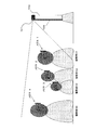
- the observers H1 to H3 are persons who desire to view the displayed 3D image as it is as a 3D image when observing the 3D image on the stereoscopic image display apparatus 100.
- the observer H4 is a person who desires only a 2D image as a display image because the 3D image cannot be recognized as a 3D image.
- the observer H1, the observer H2, and the observer H4 are adults, and the observer H3 is a child.
- the observer detection unit 101 When a 3D image is displayed on the display unit 109, the observer detection unit 101 periodically captures an image of the observer and extracts the person being photographed. Even when a 2D image is displayed on the display unit 109, if the source image from the tuner unit 106 or the external input unit 107 is a 3D image, an image of the observer is periodically captured and captured. The person who is. Note that when the source image itself from the tuner unit 106 or the external input unit 107 is a 2D image, the stereoscopic glasses 200 are not required, and thus the observer's shooting and person extraction operations are not performed.
- the observer detection unit 101 detects whether or not the person extracted from the image obtained by photographing the observer is wearing the registered stereoscopic glasses 200. As a result of detecting the wearing of the stereoscopic glasses 200, when it is determined that all the viewers are not wearing the stereoscopic glasses 200, the observer detection unit 101 instructs the control unit 103 to provide the stereoscopic glasses. Notify that there is no observer using 200.
- the control unit 103 receives the notification from the observer detection unit 101 and instructs the image processing unit 108 to display a 2D image. In response to an instruction from the control unit 103, the image processing unit 108 displays either the right-eye image or the left-eye image of the 3D image on the display unit 109.
- the observer detection unit 101 When there is an observer wearing the stereoscopic glasses 200, the observer detection unit 101 notifies the control unit 103 that there is an observer using the stereoscopic glasses 200. And instructing to extract image data for verification of the observer and the stereoscopic glasses 200 from the observer and stereoscopic glasses database 102.
- the control unit 103 receives an instruction from the observer detection unit 101 and instructs the image processing unit 108 to display a 3D image.
- the image processing unit 108 displays the right-eye image or the left-eye image of the 3D image alternately on the display unit 109 according to an instruction from the control unit 103.
- the verification image data of the stereoscopic glasses 200 is taken out in the order of registration numbers G and sent to the observer detection unit 101.
- the comparison image data of the stereoscopic glasses 200 from the control unit 103 is compared with the image data of the stereoscopic glasses 200 taken by the camera of the observer detection unit 101.
- the stereoscopic glasses 200 are specified.
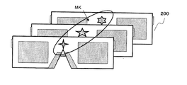
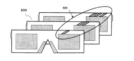
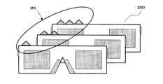
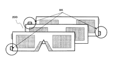
- FIG. 3A to 3D are diagrams for explaining the individual selection mark portion MK for glasses in the stereoscopic image display apparatus 100 according to the embodiment of the present invention.
- FIG. 3A shows an example in which a sorting mark is pasted as the individual sorting mark portion MK as shown in the center portion of the glasses.
- FIG. 3B shows an example in which a selection mark is attached to the peripheral portion of the eyeglass lens as the individual selection mark portion MK.
- FIG. 3C shows an example in which triangular marks are pasted on the side surfaces of the frame so that the frame portion of the glasses can be identified by the shape of the frame when the frame portion of the glasses is viewed from the front.
- FIG. 3D also shows an example in which a square mark is pasted on the side of the frame so that the frame portion of the glasses can be identified by the shape of the frame when the frame portion of the glasses is viewed from the front. .
- the observer detection unit 101 uses the control unit to store information on the combination of the observer registration number K and the registration number G of the stereoscopic glasses 200 stored in the work memory. Deliver to 103.
- the controller 103 identifies the observer and the observer identified from the stereoscopic glasses database 102 based on the information of the combination of the observer registration number K received from the observer detector 101 and the registration number G of the stereoscopic glasses 200.
- FIG. 4 is a diagram for explaining the transmission timing of the synchronization signal and the control signal in the stereoscopic image display apparatus 100 according to the embodiment of the present invention.
- FIG. 4A shows the display timing of the 3D image display image signal displayed on the display unit 109.
- the right-eye image signal and the left-eye image signal are alternately displayed on the display unit 109.
- FIG. 4B shows a synchronization signal synchronized with the display image signal, which is H when the right image signal is displayed on the display unit 109 and L when the left eye image signal is displayed.
- the control signal is transmitted superimposed on this synchronization signal.
- a control signal transmission section is provided in a section of one cycle in which the right eye image and the left eye image are displayed.
- FIG. 4C shows a signal for controlling opening and closing of the shutter transmitted from the synchronization circuit 202 to the right eye shutter 204.
- the shutter is opened, and the right eye image can be seen by the observer's right eye.
- the shutter is closed, and the left eye image cannot be seen with the observer's right eye.
- FIG. 4D shows a signal for controlling opening / closing of the shutter transmitted from the synchronization circuit 202 to the left-eye shutter 205.
- H the shutter is opened, and the left eye image can be seen with the left eye of the observer.
- L the shutter is closed, and the right eye image cannot be seen with the left eye of the observer.
- the synchronization circuit 202 of the stereoscopic glasses 200 is switched between a mode for viewing a 3D image and a mode for viewing a 2D image by a control signal from the control unit 203. If the mode for viewing the 3D image is set, the synchronization circuit 202 of the stereoscopic glasses 200 synchronizes with the synchronization signal received by the receiving unit 201 and the right eye shutter 204 for viewing the right eye image and the left eye. The opening / closing timing of the left-eye shutter 205 for viewing the image for use is controlled.
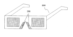
- FIGS. 5A to 5C are diagrams for explaining the attachment / detachment detection unit 206 at the time of wearing and detaching glasses in the stereoscopic glasses 200 according to the embodiment of the present invention.
- the example in the case of attaching to the three parts of the stereoscopic glasses 200 of the attachment / detachment detection unit 206 is shown.
- FIG. 5A shows a case where the attachment / detachment detection unit 206 is in the nose pad portion. In this case, it is detected whether or not current flows through the small push switch or the left and right nose pad portions, and it is determined whether the observer wears or removes the stereoscopic glasses 200.
- FIG. 5B shows a case where the attachment / detachment detection unit 206 is in a portion that touches the skin of the head of the frame of the stereoscopic glasses 200, detects the electrostatic capacitance of the skin of the head, and the observer uses the stereoscopic glasses 200. Determine whether it is attached or detached.
- FIG. 5C shows a case where the attachment / detachment detection unit 206 is in a portion where the ear of the frame of the stereoscopic glasses 200 hits, that is, a portion where the frame rides on the ear. In this case, a small push switch or a capacitance is detected. Then, a sensor for detecting attachment / detachment is provided to determine whether the observer wears or removes the stereoscopic glasses 200.
- the attachment / detachment detection unit 206 By configuring the attachment / detachment detection unit 206 as shown in FIGS. 5A to 5C, when the observer wears the stereoscopic glasses 200, it is detected that the attachment / detachment detection unit 206 is attached, and each of the stereoscopic glasses 200 is detected. Power is supplied to the circuit.
- the stereoscopic glasses 200 are initialized and started up in a 3D mode in which a 3D image can be viewed. Further, when the separation is detected, the power supply to each circuit of the stereoscopic glasses 200 is stopped.
- the viewers H1 to H4 wear the glasses 1 to 4 configured by the stereoscopic glasses 200 of the present invention, respectively.
- the 3D image can be viewed as it is as a 3D image according to the individual data. Further, the observer H4 can wear the glasses 4 according to the individual data and view the 3D image as a 2D image.
- an Example is an illustration in all the points, Comprising: It is not necessarily limited to these.
- a stereoscopic image display device and stereoscopic glasses are illustrated, but a 3D image signal and a synchronization signal are output, the synchronization signal is received, and a viewer can use a pair of glasses that can be stereoscopically viewed. It is sufficient that a stereoscopic image can be provided, and the present invention is not limited to a stereoscopic image display device and stereoscopic glasses.
- the present invention provides a 3D television, 3D projector, digital video recorder, portable movie player, cellular phone, car navigation system, portable or stationary BD / DVD player, PC
- the present invention can be widely applied to devices that can output or display 3D image signals.
- Example 2 The second embodiment relates to an embodiment in which when a plurality of viewers view a 2D image or a 3D image by the stereoscopic image display device 100, priority is set for a plurality of viewers or a plurality of stereoscopic glasses 200.
- the stereoscopic image display apparatus 100 identifies a higher-priority observer or a higher-priority stereoscopic glasses 200 and corresponds to a specified observer or an observer wearing the identified stereoscopic glasses 200. Are displayed on the display unit 109.
- An observer table and an eyeglass table are stored in a predetermined area of the observer and stereoscopic eyeglasses database (database) 102 which is a storage means.
- the observer table is a table for managing the attributes of the observer.
- the glasses table is a table for managing attributes of the stereoscopic glasses 200.
- the observer table and the glasses table will be described in detail.
- FIG. 7 is a diagram showing an example of the record layout of the observer table 1T.
- the observer table 1T includes columns of registration number K, observer image, mode, name, and priority.
- the registration number K is a number for identifying an observer who views an image displayed on the display unit 109 of the stereoscopic image display device 100.
- the registration number K is a primary key of the observer table 1T.
- the observer image is an image of the observer taken by the camera of the observer detection unit (detection unit) 101.
- the image data of the observer itself may be stored in the observer / stereoscopic eyeglass database 102 and may not necessarily be stored in the observer table 1T. In such a case, an address or path relating to the image data of the observer is stored in the observer image sequence.
- the priority is the priority between the observers regarding the mode when a plurality of observers are registered in the observer table 1T.
- the stereoscopic image display apparatus 100 displays an image corresponding to the observer's mode having a higher priority on the display unit 109.
- the observer with higher priority is the observer with the highest priority among the plurality of observers detected by the observer detection unit 101.
- the priority is, for example, a number, and a smaller number is stored in the priority as an observer with higher authority. The priority is not set to the same value for different observers. It should be noted that a larger number may be stored in the priority level for a more powerful observer.
- observer table 1T may further include columns such as age, height, sex, nickname, and preference genre.
- FIG. 8 is a diagram showing an example of a record layout of the glasses table 2T.
- the glasses table 2T includes columns of a registration number G, a glasses image, a mark position, a serial number, and a priority.
- the registration number G is a number for identifying the stereoscopic glasses 200.
- the registration number G is a primary key of the glasses table 2T.
- the glasses image is an image of the stereoscopic glasses 200 taken by the camera of the observer detection unit 101.
- the image data itself of the stereoscopic glasses 200 may be stored in the observer and stereoscopic glasses database 102, and may not necessarily be stored in the glasses table 2T. In such a case, an address or path relating to image data of the stereoscopic glasses 200 is stored in the eyeglass image sequence.
- the mark position is a position where the individual selection mark portion MK is attached to the stereoscopic glasses 200.
- various positions in the stereoscopic glasses 200 shown in FIGS. 3A to 3D are stored as the mark positions.
- the serial number is, for example, a serial number issued when the stereoscopic glasses 200 are manufactured.
- the priority is a priority order related to mode selection when a plurality of stereoscopic glasses 200 are registered in the glasses table 2T.
- the stereoscopic image display device 100 displays an image corresponding to the mode of the observer wearing the higher-priority stereoscopic glasses 200.
- the stereoscopic glasses 200 having higher priority are the stereoscopic glasses 200 having the highest priority among the plurality of stereoscopic glasses 200 detected by the observer detection unit 101.
- the priority is, for example, a number, and a smaller number is stored in the priority as the stereoscopic glasses 200 having a higher priority. The same priority is not set for different stereoscopic glasses 200. Note that a higher number may be stored in the priority as the stereoscopic glasses 200 with higher priority.
- the glasses table 2T may further include columns such as a manufacturer name, a model name, a model number, a color, and a model year.
- FIG. 9 is a diagram illustrating an example of the selection screen 3f.
- the selection screen 3f is a user interface for registering attribute information of the observer and the stereoscopic glasses 200 in the observer table 1T and the glasses table 2T, respectively.
- the control unit (observer registration unit, glasses registration unit, collation unit, determination unit) 103 displays a selection screen 3f on the display unit 109 when a registration button of a remote controller (not shown) is pressed.
- the selection screen 3f includes an observer registration button 31b, a stereoscopic glasses registration button 32b, an observer and stereoscopic glasses both registration button 33b, and a return button 34b.
- the observer operates various keys on the remote controller to select each button displayed on the selection screen 3f and presses the selected button.
- the control unit 103 interrupts the registration process of the observer or the stereoscopic glasses 200 with respect to the observer table 1T or the glasses table 2T, and displays an initial image on the display unit 109.
- the control unit 103 zooms in on an object such as an observer and stereoscopic glasses 200 with the camera with respect to the observer detection unit 101, and registers for an appropriate size. Send instructions to take an image.
- the control unit 103 detects the observer from the image captured by the camera with respect to the observer detection unit 101, and zooms so that the entire observer is displayed on the screen. Instructs the user to take the image.
- the observer detection unit 101 may extract the face part of the observer from the image captured by the camera and take an image corresponding to the extracted face part of the observer.
- the observer detection unit 101 may take an image of the upper body part of the observer.
- the observer detection part 101 may image
- FIG. 10 is a diagram illustrating an example of the selection screen 3f.
- FIG. 10 is also a confirmation screen for confirming with the observer whether or not to shift to the record registration process in the observer table 1T or the glasses table 2T.
- This confirmation screen includes an observer screen 31f at the top of the screen, a yes button 35b and a no button 36b at the bottom of the screen.
- the observer screen 31f is a child screen that displays an image of the observer taken by the camera of the observer detection unit 101.
- the control unit 103 displays the selection screen 3f of FIG.
- the Yes button 35b is pressed, the control unit 103 transitions to the next screen.
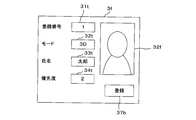
- FIG. 11 is a diagram illustrating an example of the selection screen 3f.
- the control unit 103 displays the selection screen 3f in FIG.
- FIG. 11 is also an input screen for inputting record information to be registered in the observer table 1T.
- This input screen includes an observer screen 32f at the upper right of the screen, a text box at the left of the screen, and a registration button 37b at the lower right of the screen.
- the text box on the left side of the screen includes a registration number text box 31t, a mode text box 32t, a name text box 33t, and a priority text box 34t.
- the observer screen 32 f is a sub-screen that displays an image of the observer taken by the camera of the observer detection unit 101.
- the observer image displayed on the observer screen 32f may be the same as or different from the observer image displayed on the observer screen 31f of FIG.
- the image displayed on the observer screen 32f may be an image obtained by further enlarging the face portion of the observer image displayed on the observer screen 31f.
- the image of the observer displayed on the observer screen 32f is an image stored in the observer image of the observer table 1T.
- the registration number text box 31t, the mode text box 32t, the name text box 33t, and the priority text box 34t are screen controls for inputting information corresponding to the registration number K, mode, name, and priority of the observer table 1T, respectively. It is.
- the observer inputs necessary information in these text boxes from the remote control. Note that the input information is not a text box, but may be a list-type list box or combo box that can be selected and input.
- the control unit 103 registers the observer image and various attributes displayed on the selection screen 3f in FIG. 11 in the observer table 1T.
- the control unit 103 displays the selection screen 3f in FIG.
- the control unit 103 causes the observer detection unit 101 to detect the face of the observer shown in the image captured by the camera, and displays an image of the face part of the observer wearing the stereoscopic glasses 200 as shown in FIG. Displayed on the observer screen 31f.
- FIG. 12 is a diagram illustrating an example of the selection screen 3f.
- the control unit 103 displays the selection screen 3f in FIG. FIG. 12 is also an input screen for inputting record information to be registered in the glasses table 2T.
- This input screen includes a glasses screen 33f at the upper right of the screen, a text box at the left of the screen, and a registration button 38b at the lower right of the screen.
- the text box on the left side of the screen includes a registration number text box 35t, a mark position text box 36t, a serial number text box 37t, and a priority text box 38t.
- the glasses screen 33f is a small screen that displays the stereoscopic glasses 200 taken by the camera of the observer detection unit 101.
- the control unit 103 instructs the observer detection unit 101 to zoom up the portion of the stereoscopic glasses 200 worn by the observer captured by the camera.
- the control unit 103 displays the image of the stereoscopic glasses 200 having an appropriate size that has been zoomed up on the glasses screen 33f.
- the image of the stereoscopic glasses 200 displayed on the glasses screen 33f is an image stored in the glasses image of the glasses table 2T. Note that the image of the stereoscopic glasses 200 may be taken separately from the observer.
- control unit 103 instructs the observer detection unit 101 to shoot the stereoscopic glasses 200 alone based on the operation signal from the remote controller, and the stereoscopic glasses captured by the camera of the observer detection unit 101. 200 images are displayed on the glasses screen 33f.
- the registration number text box 35t and the mark position text box 36t are screen controls for inputting information corresponding to the registration number G and the mark position of the glasses table 2T, respectively.
- the serial number text box 37t and the priority text box 38t are screen controls for inputting information corresponding to the serial number and priority of the glasses table 2T, respectively.
- the observer inputs necessary information in these text boxes from the remote control. Note that the input information is not a text box, but may be a list-type list box or combo box that can be selected and input.
- the control unit 103 registers the image and various attributes of the stereoscopic glasses 200 displayed on the selection screen 3f in FIG. 12 in the glasses table 2T.
- the control unit 103 controls both the case where both the observer and stereoscopic glasses registration button 33b in FIG. 9 are pressed, and the case where the observer registration button 31b and the stereoscopic glasses registration button 33b in FIG. 9 are pressed. These processes are executed sequentially. At that time, the control unit 103 may execute either the process when the observer registration button 31b is pressed or the process when the stereoscopic eyeglass registration button 33b is pressed first.
- the operation of the stereoscopic image display apparatus 100 will be described. First, an operation of specifying an observer with a higher priority and displaying an image of a mode corresponding to the specified observer on the display unit 109 will be described. Next, an operation of specifying the stereoscopic glasses 200 having higher priority and displaying an image in a mode corresponding to the observer wearing the specified stereoscopic glasses 200 on the display unit 109 will be described.
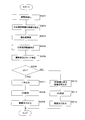
- FIG. 13 is a flowchart illustrating an example of a procedure of processing executed by the control unit 103.
- the process of FIG. 13 specifies the mode selected by the observer by specifying the observer based on the priority.
- the control unit 103 periodically photographs a plurality of observers on the observer detection unit 101. Are extracted from the captured image (step S101). Based on the extracted images of the plurality of observers, the control unit 103 searches the observer table 1T for the priority and mode of the observer corresponding to the observer image (step S102).
- step S102 the control unit 103 observes in both images from the observer image captured by the observer detection unit 101 and the observer image stored in the observer image row of the observer table 1T. Check whether the person is the same. When the observers are the same as a result of this collation, the control unit 103 extracts the priority and mode of the observer from the record of the observer table 1T corresponding to the observer photographed by the observer detection unit 101.
- the control unit 103 determines whether the identified highest-priority observer mode is 2D. It is determined whether or not (step S105).
- the control unit 103 converts the image processing unit 108 into a right-eye image or a left-eye image in the 3D image. One of the image signals is instructed to be output to the display unit 109 (step S106).
- the control unit 103 sets the 2D mode in the control signal transmitted to the stereoscopic glasses 200 (step S107).
- the control unit 103 superimposes the set control signal on the synchronization signal, outputs the superimposed synchronization signal to the transmission unit 105 (step S108), and ends the process.
- step S105 When it is determined that the identified highest priority observer mode is not 2D (step S105: NO), the control unit 103 outputs an image signal related to the 3D image to the display unit 109 to the image processing unit 108. Is instructed to do so (step S109). In addition, the control unit 103 sets the 3D mode in the control signal transmitted to the stereoscopic glasses 200 (Step S110). The control unit 103 superimposes the set control signal on the synchronization signal, outputs the superimposed synchronization signal to the transmission unit 105 (step S111), and ends the process.
- the main subject of processing is the control unit 103, but the main subject of processing may be the observer detection unit 101.
- the transmission unit 105 of the stereoscopic image display device 100 receives a synchronization signal on which a control signal is superimposed from the control unit, and transmits the received synchronization signal to the stereoscopic glasses 200.
- the receiving unit 201 of the stereoscopic glasses 200 receives the synchronization signal on which the control signal is superimposed from the transmission unit 105, and separates the synchronization signal and the control signal.
- the reception unit 201 transmits the separated control signal to the control unit 203 and transmits the separated synchronization signal to the synchronization circuit 202.
- control unit 203 instructs the synchronization circuit 202 to alternately open and close the right-eye shutter 204 and the left-eye shutter 205 in synchronization with the synchronization signal.
- FIG. 14 is a flowchart illustrating an example of a procedure of processing executed by the control unit 103.
- the process of FIG. 14 specifies the viewer wearing the stereoscopic glasses 200 and the mode selected by the viewer by specifying the stereoscopic glasses 200 based on the priority. In the process of FIG. 14, it is assumed that all the observers are wearing stereoscopic glasses 200.
- the control unit 103 periodically photographs a plurality of observers on the observer detection unit 101. Are extracted from the captured image (step S201).
- the control unit 103 extracts an image of the stereoscopic glasses 200 worn by the observer from the extracted images of the plurality of observers (step S202).
- the control unit 103 searches for a priority from the glasses table 2T based on the extracted image of the stereoscopic glasses 200 (step S203).
- step S203 the control unit 103 determines whether or not the stereoscopic glasses 200 extracted from the image captured by the observer detection unit 101 and the stereoscopic glasses 200 stored in the glasses image sequence of the glasses table 2T are the same. Is matched.
- the control unit 103 determines the stereoscopic from the record of the glasses table 2T corresponding to the stereoscopic glasses 200 taken by the observer detection unit 101. The priority of the viewing glasses 200 is extracted.
- the control unit 103 may use the mark position of the glasses table 2T for the above-described collation.
- control unit 103 executes the collation between the extracted image of the stereoscopic glasses 200 and the glasses image of the glasses table 2T at a higher speed. be able to.
- a weight column corresponding to the observer may be added to the observer table 1T.
- the weight is, for example, the age of the observer, the program viewing time of the observer, or the like.
- a weight corresponding to the observer is registered.
- the priority which added the said weight is made into a new priority, and an observer is specified by a new priority.
- the stereoscopic image display apparatus 100 may switch the image to be displayed on the display unit 109 between the 2D image and the 3D image based on the mode corresponding to the observer specified by the new priority.
- the stereoscopic image display device 100 when an observer with high priority wears the stereoscopic glasses 200, an image in a mode selected by the observer with high priority is displayed on the display unit 109. Thereby, when the selected mode differs among a plurality of observers, the stereoscopic image display apparatus 100 can automatically display either the 2D image or the 3D image on the display unit 109. Similarly, according to the stereoscopic image display apparatus 100, a person with high authority can wear the high-priority stereoscopic viewing glasses 200, and thus the same effects as described above can be achieved.
- Example 2 is as described above, and the other parts are the same as Example 1. Accordingly, corresponding parts are denoted by the same reference numerals, and detailed description thereof is omitted.
- FIG. 15 is a diagram showing another example of the record layout of the observer table 1T.
- the glasses table 2T of the third embodiment is set with different priorities when the stereoscopic glasses 200 are different (see FIG. 8).
- the stereoscopic glasses 200 worn by Taro have higher priority than the stereoscopic glasses 200 worn by Hanako.
- Taro's mode is 2D
- Hanako's mode is 3D (see FIG. 15). Therefore, when the image of the broadcast program selected by the tuner unit 106 or the source image received by the external input unit 107 is a 3D image, the stereoscopic image display device 100 forcibly selects the 2D mode image selected in advance by Taro. It is displayed on the display unit 109.
- the 2D mode image here is an image for the right eye or an image for the left eye related to the 3D image.
- FIG. 16 is a flowchart illustrating another example of the processing procedure executed by the control unit 103.
- the control unit 103 periodically photographs a plurality of observers on the observer detection unit 101. Are extracted from the captured image (step S301). Based on the extracted images of the plurality of observers, the control unit 103 searches the observer table 1T for the priority and mode of the observer corresponding to the observer image (step S302).
- the control unit 103 identifies an observer with the highest priority among the extracted observers (step S303).
- the control unit 103 determines whether or not there are a plurality of observers identified in step S303 (step S304). When it is determined that there are not a plurality of observers identified in step S303 (step S304: NO), the control unit 103 determines a mode corresponding to the identified single observer as a mode of an image to be displayed on the display unit 109. (Step S305). Thereafter, the control unit 103 advances the process to step S310.
- step S304 determines that there are a plurality of observers identified in step S303 (step S304: YES), the stereoscopic glasses worn by each observer from the images of the identified plurality of observers. 200 images are extracted (step S306).
- the control unit 103 searches for a priority from the glasses table 2T based on the extracted images of the stereoscopic glasses 200 (step S307).
- the control unit 103 identifies the stereoscopic glasses 200 having the highest priority that has been searched (step S308).
- the control unit 103 determines the mode of the observer wearing the specified stereoscopic glasses 200 as the image mode to be displayed on the display unit 109 (step S309).
- the processing after step S310 is the same as the processing after step S105 shown in FIG. Also, the flow after step S310 in FIG. 16 is omitted.
- the main subject of processing is the control unit 103, but the main subject of processing may be the observer detection unit 101.
- a plurality of observers having the same priority are specified, and then the stereoscopic glasses 200 are specified.
- this order may be reversed, first, a plurality of stereoscopic glasses 200 having the same priority may be specified, and then an observer may be specified.
- the same priority can be set for different stereoscopic glasses 200 as the priority of the glasses table 2T.
- the priority of the observer table 1T cannot be set to the same priority for different observers.
- the control unit 103 extracts the images of the plurality of stereoscopic glasses 200 from the image photographed by the observer detection unit 101, and detects the priority from the glasses table 2T based on the extracted images.
- the control unit 103 extracts an image of each observer wearing the stereoscopic glasses 200.
- the control unit 103 searches the priority and mode from the observer table 1T based on the extracted images of the observers.
- the control unit 103 determines the mode corresponding to the searched highest observer for the image to be displayed on the display unit 109.
- the stereoscopic image display device 100 even when there are a plurality of observers having the same priority regarding the mode selection, it is possible to prevent a dispute regarding the display mode.
- the stereoscopic image display device 100 sets the mode of an image to be displayed on the display unit 109 based on the priority set for the stereoscopic glasses 200 worn by the observer. decide. Therefore, when the viewer with higher priority wears the glasses 200 for stereoscopic viewing with higher priority, the mode of the image displayed on the display unit 109 is automatically determined. Easy to use for observers.
- Example 3 is as described above, and the other parts are the same as those in Examples 1 and 2. Therefore, corresponding parts are denoted by the same reference numerals, and detailed description thereof is omitted.
- the stereoscopic image display apparatus and stereoscopic glasses according to the present invention relate to realizing a display state of a 3D image or a 2D image desired by an individual observer without burdening the observer with a switching operation.
Landscapes
- Physics & Mathematics (AREA)
- Engineering & Computer Science (AREA)
- General Physics & Mathematics (AREA)
- Multimedia (AREA)
- Signal Processing (AREA)
- Optics & Photonics (AREA)
- Computer Hardware Design (AREA)
- Theoretical Computer Science (AREA)
- Testing, Inspecting, Measuring Of Stereoscopic Televisions And Televisions (AREA)
- Controls And Circuits For Display Device (AREA)
- Control Of Indicators Other Than Cathode Ray Tubes (AREA)
Abstract
Description
図1は、一実施例に係る立体画像表示装置100の要部構成を示す機能ブロック図と、立体視用眼鏡200の要部構成を示す機能ブロック図である。
ここで、「観察者登録」が選択されている場合は、観察者検出部101では、カメラが捕らえている画像の中の映っている人間を検出し、その人物の全体が表示されるようにズーミングし画像を撮影する。また、顔の部分を抽出し、撮影するようにしても良い。更には、上半身の部分を撮影するようにしても良い。更には、観察者の指定する任意の大きさの画像を撮影しても良い。
また、「立体視用眼鏡登録」が選択されている場合は、観察者検出部101では、カメラが捕らえている画像の中の映っている観察者の顔を検出し、観察者に装着されている立体視用眼鏡200の部分をズームアップしながら、立体視用眼鏡200の適正な大きさの登録用画像データを撮る。
更に、「観察者及び立体視用眼鏡の両方登録」が選択された場合は、「観察者登録」が選択されている場合と「立体視用眼鏡登録」が選択されている場合の両方の操作が順次行われる。優先順位は無いので、どちらを先に行っても良い。
また、立体視用眼鏡200を装着している観察者がいる場合は、観察者検出部101は、制御部103に対して、立体視用眼鏡200を使用している観察者がいること通知し、観察者及び立体視用眼鏡データベース102から観察者及び立体視用眼鏡200の照合用の画像データを取り出すように指示する。制御部103は、観察者検出部101からの指示を受け、画像処理部108に対して3D画像を表示するように指示する。画像処理部108は、制御部103からの指示により、表示部109に、3D画像の右目用画像又は左目用画像を交互に表示するようにする。
図4(a)は、表示部109に表示される3D画像の表示用画像信号の表示タイミングを示している。表示部109に右目用画像信号と左目用画像信号が交互に表示される。図4(b)は表示用画像信号に同期した同期信号であり、右用画像信号が表示部109に表示されている時にはH、左目用画像信号が表示されている場合にはLとなる。制御信号は、この同期信号に重畳して送信される。ここに表示した例は、右目画像と左目画像が表示されている1サイクルの区間に制御信号送出区間を設けたものである。この区間の長さは、1サイクルによらず複数のサイクルの区間で送出しても良い。図4(c)は同期回路202から右目用シャッター204に送信されるシャッターの開閉を制御するための信号である。Hの時、シャッターが開き、観察者の右目では右目用の画像を見ることができる。Lの時は、シャッターが閉じ、観察者の右目では左目用の画像は見ることができない。図4(d)は同期回路202から左目用シャッター205に送信されるシャッターの開閉を制御するための信号である。Hの時、シャッターが開き、観察者の左目では左目用の画像を見ることができる。Lの時は、シャッターが閉じ、観察者の左目では右目用の画像は見ることができない。
3D画像を見るためのモードが設定されていれば、立体視用眼鏡200の同期回路202は、受信部201で受信した同期信号に同期して、右目画像を見るための右目用シャッター204と左目用画像を見るための左目用シャッター205の開閉タイミングの制御を行っている。同期信号を受信している間は、受信した同期信号に合わせて、右目用シャッター204と左目用シャッター205の開閉を行い、同期信号に制御信号が含まれてくる制御信号送出区間の間は、同期信号が入手できないため、制御信号送出区間前に受信している同期信号を維持し、同期信号が自走するように構成されている。
実施例2は、複数の観察者が立体画像表示装置100により2D画像又は3D画像を見る場合、複数の観察者又は複数の立体視用眼鏡200に優先度を設定する実施例に関する。立体画像表示装置100は、優先度がより高い観察者又は優先度がより高い立体視用眼鏡200を特定し、特定した観察者又は特定した立体視用眼鏡200を装着した観察者に対応するモードの画像を表示部109に表示する。
氏名は、観察者の名前である。
尚、権限の強い観察者ほど大きい数字を優先度に格納しても良い。
シリアル番号は、例えば立体視用眼鏡200の製造時に発番されたシリアル番号である。
尚、優先度の高い立体視用眼鏡200ほど大きい数字を優先度に格納しても良い。
選択画面3fは、観察者登録ボタン31b、立体視用眼鏡登録ボタン32b、観察者及び立体視用眼鏡の両方登録ボタン33b及び戻るボタン34bを含む。観察者は、リモコンの各種キーを操作することにより、選択画面3fに表示された各ボタンを選択し、選択した各ボタンを押下する。
尚、立体視用眼鏡200の画像は、観察者とは別に撮影されても良い。かかる場合、制御部103は、リモコンからの操作信号に基づき、観察者検出部101に立体視用眼鏡200単体を撮影するように指示し、観察者検出部101のカメラが撮影した立体視用眼鏡200の画像を眼鏡画面33fに表示する。
制御部103は、チューナー部106が受信した放送番組の画像又は外部入力部107が受け付けたソース画像が3D画像である場合、観察者検出部101に定期的に複数の観察者を撮影し、複数の観察者を撮影した画像から抽出させる(ステップS101)。制御部103は、抽出された複数の観察者各人の画像に基づいて、観察者テーブル1Tから観察者画像に対応する観察者の優先度及びモードを検索する(ステップS102)。
立体視用眼鏡200の受信部201は、制御信号が重畳された同期信号を送信部105から受信し、同期信号及び制御信号を分離する。受信部201は、分離した制御信号を制御部203に送信し、分離した同期信号を同期回路202に送信する。制御部203は、受信した制御信号が2Dモードである場合、同期回路202に対して、右目用画像又は左目用画像のどちらか一方の同期信号に同期して、右目用シャッター204及び左目用シャッター205を開くように指示する。或いは、制御部203は、制御信号が2Dモードである場合、立体視用眼鏡200を電源がオフの状態にしても良い。
制御部103は、チューナー部106が受信した放送番組の画像又は外部入力部107が受け付けたソース画像が3D画像である場合、観察者検出部101に定期的に複数の観察者を撮影し、複数の観察者を撮影した画像から抽出させる(ステップS201)。
尚、ステップS203において、制御部103は、眼鏡テーブル2Tのマーク位置を、上述の照合のために利用してもよい良い。立体視用眼鏡200における個別選別用マーク部MKの位置が予め判明している場合、制御部103は抽出した立体視用眼鏡200の画像及び眼鏡テーブル2Tの眼鏡画像の照合をより高速に実行することができる。
ステップS206以降の処理は、図13に示したステップS105以降の処理と同一であり、その説明を省略する。
同様に、立体画像表示装置100によれば、権限の高い人が優先度の高い立体視用眼鏡200を装着することにより、上述と同様の効果を奏することができる。
決定権を持つ観察者の優先度を高く設定することにより、立体映像表示装置100は自動的に優先度の高い人に対応するモードの画像を表示することで、表示モードの争いを防止する。また、例えば親子からなる複数の観察者が画像を見る場合、親の優先度を高く設定することにより、又は親が優先度の高い立体視用眼鏡200を装着することにより、立体画像表示装置100は子供が長時間3D画像を見てしまうことを防止することができる。
実施例3は、複数の観察者に設定した優先度が同一である場合、それらの観察者のうち優先度がより高い立体視用眼鏡200を装着している観察者を特定し、特定した観察者に対応するモードの画像を表示部109に表示する実施例に関する。
登録番号K=1の太郎と登録番号K=4の花子とは、優先度が共に1である。しかし、太郎が装着している登録番号G=1の立体視用眼鏡200の優先度は1であるのに対し、花子が装着している登録番号G=4の立体視用眼鏡200の優先度は4である。そのため、太郎が装着している立体視用眼鏡200の方が、花子が装着している立体視用眼鏡200よりも優先度が高い。
ところで、太郎のモードは2Dであり、花子のモードは3Dである(図15参照)。そのため、立体画像表示装置100は、チューナー部106が選局した放送番組の画像又は外部入力部107が受け付けたソース画像が3D画像である場合、太郎が予め選択した2Dモードの画像を強制的に表示部109に表示する。ここでの2Dモードの画像とは、3D画像に係る右目用画像又は左目用画像である。
制御部103は、チューナー部106が受信した放送番組の画像又は外部入力部107が受け付けたソース画像が3D画像である場合、観察者検出部101に定期的に複数の観察者を撮影し、複数の観察者を撮影した画像から抽出させる(ステップS301)。制御部103は、抽出された複数の観察者各人の画像に基づいて、観察者テーブル1Tから観察者画像に対応する観察者の優先度及びモードを検索する(ステップS302)。
ステップS310以降の処理は、図13に示したステップS105以降の処理と同一であり、その説明を省略する。また、図16におけるステップS310以降のフローを省略する。
制御部103は、観察者検出部101に撮影した画像から複数の立体視用眼鏡200の画像を抽出し、抽出した画像に基づいて、眼鏡テーブル2Tから優先度を検出する。制御部103は、最も高い優先度の立体視用眼鏡200が複数である場合、各立体視用眼鏡200を装着している観察者各々の画像を抽出する。制御部103は、抽出した観察者各々の画像に基づいて、観察者テーブル1Tから優先度及びモードを検索する。制御部103は、検索した優先度が最も高い観察者に対応したモードを表示部109に表示する画像のモードに決定する。
立体画像表示装置100は、観察者の優先度が同じ場合、観察者が装着している立体視用眼鏡200に対して設定された優先度に基づいて、表示部109に表示する画像のモードを決定する。従って、より優先度の高い観察者がより優先度の高い立体視用眼鏡200を装着することにより、表示部109に表示する画像のモードは自動的に決定されるので、立体画像表示装置100は観察者にとって使い勝手が良い。
101 観察者検出部(検出部)
102 観察者及び立体視用眼鏡データベース(データベース)
103 制御部(観察者登録手段、眼鏡登録手段、照合手段、判定手段)
105 送信部
106 チューナー部
107 外部入力部
108 画像処理部
109 表示部
200、メガネ1~メガネn 立体視用眼鏡
201 受信部
202 同期回路
203 制御部
204 右目用シャッター
205 左目用シャッター
206 着脱検知部
MK 個別選別用マーク部
観察者H1~観察者H4、観察者
1T 観察者テーブル
2T 眼鏡テーブル
3f 選択画面
Claims (19)
- 立体画像信号を表示部に表示可能な立体画像表示装置において、
前記表示部に3D画像又は2D画像を出力する画像処理部と、
前記立体画像を観察する観察者を検出するための観察者検出部と、
前記観察者検出部より検出された個別データを登録する観察者登録手段と、
前記立体画像を観察するための立体視用眼鏡の個別データを登録する眼鏡登録手段と、
前記観察者の個別データと立体視用眼鏡の個別データとを管理する観察者及び立体視用眼鏡データベースと、
前記観察者及び立体視用眼鏡データベースの照合結果に基づき、前記表示部に表示される立体画像信号を立体画像として見るための同期信号を送信するための送信部と
を備える
ことを特徴とする立体画像表示装置。 - 請求項1記載の立体画像表示装置であって、
前記観察者検出部は、表示部に向いている観察者と前記観察者が装着している前記立体視用眼鏡を前記観察者及び立体視用眼鏡データベースにより検出し、前記観察者及び立体視用眼鏡データベースに格納されている観察者の関連情報より、前記観察者が要望する表示状態になるように、前記観察者が装着している前記立体視用眼鏡に対して3Dモードか2Dモードかを指示する制御信号を前記同期信号に重畳した
ことを特徴とする立体画像表示装置。 - 請求項1又は請求項2記載の立体画像表示装置であって、
前記観察者検出部で検出された全ての前記観察者が前記立体視用眼鏡を着用していないと前記観察者検出部が判断した場合は、前記画像処理部より出力する3D画像は、右目用画像又は左目用画像のどちらか一方を出力する
ことを特徴とする立体画像表示装置。 - 請求項1又は請求項2記載の立体画像表示装置であって、
前記観察者検出部で検出された全ての前記観察者の関連情報が2D表示を要望している場合は、前記画像処理部より出力する3D画像は、右目用画像又は左目用画像のどちらか一方を出力する
ことを特徴とする立体画像表示装置。 - 画像信号に係る立体画像又は平面画像を表示部に表示する立体画像表示装置において、
前記表示部に立体画像又は平面画像に係る画像信号を出力する画像処理部と、
前記表示部に表示される画像を観察する観察者及び該表示部に表示される立体画像を観察するための立体視用眼鏡を検出する検出部と、
前記観察者及び立体視用眼鏡の属性情報を登録するデータベースと、
前記検出部が検出した観察者を前記データベースに登録する観察者登録手段と、
前記検出部が検出した立体視用眼鏡を前記データベースに登録する眼鏡登録手段と、
前記検出部が検出した観察者又は立体視用眼鏡に基づいて、前記データベースに登録された属性情報を照合する照合手段と
を備え、
前記観察者登録手段は、前記検出部が検出した観察者及び観察者間における優先度を対応付けて前記データベースに登録するようにしてあり、
前記照合手段が照合した照合結果に基づいて、前記検出部が検出した観察者のうち最も優先度の高い観察者が前記立体視用眼鏡を着用しているか否かを判定する判定手段を備え、
前記画像処理部は、前記判定手段が最も優先度の高い観察者が前記立体視用眼鏡を着用していないと判定した場合、立体画像における右目用画像又は左目用画像に係る画像信号を前記表示部に出力するようにしてあり、
前記表示部は、前記画像処理部が出力した前記画像信号に係る画像を表示するようにしてある
ことを特徴とする立体画像表示装置。 - 画像信号に係る立体画像又は平面画像を表示部に表示する立体画像表示装置において、
前記表示部に立体画像又は平面画像に係る画像信号を出力する画像処理部と、
前記表示部に表示される画像を観察する観察者及び該表示部に表示される立体画像を観察するための立体視用眼鏡を検出する検出部と、
前記観察者及び立体視用眼鏡の属性情報を登録するデータベースと、
前記検出部が検出した観察者を前記データベースに登録する観察者登録手段と、
前記検出部が検出した立体視用眼鏡を前記データベースに登録する眼鏡登録手段と、
前記検出部が検出した観察者又は立体視用眼鏡に基づいて、前記データベースに登録された属性情報を照合する照合手段と、
該照合手段が照合した照合結果に基づいて、前記表示部が表示する立体画像に対応する同期信号を前記立体視用眼鏡に送信する送信部と
を備え、
前記観察者登録手段は、前記検出部が検出した観察者、観察者間における優先度及び平面画像又は立体画像の表示選択を対応付けて前記データベースに登録するようにしてあり、
前記照合手段が照合した照合結果に基づいて、前記検出部が検出した観察者のうち最も優先度の高い観察者が前記立体視用眼鏡を着用しているか否かを判定する判定手段を備え、
前記画像処理部は、前記判定手段が最も優先度の高い観察者が前記立体視用眼鏡を着用していないと判定した場合、立体画像における右目用画像又は左目用画像に係る画像信号を前記表示部に出力するようにしてあり、
前記表示部は、前記画像処理部が出力した前記画像信号に係る画像を表示するようにしてあり、
前記送信部は、前記データベースに登録された平面画像又は立体画像の表示選択に対応する制御信号が重畳された前記同期信号を前記立体視用眼鏡に送信するようにしてある
ことを特徴とする立体画像表示装置。 - 画像信号に係る立体画像又は平面画像を表示部に表示する立体画像表示装置において、
前記表示部に立体画像又は平面画像に係る画像信号を出力する画像処理部と、
前記表示部に表示される画像を観察する観察者及び該表示部に表示される立体画像を観察するための立体視用眼鏡を検出する検出部と、
前記観察者及び立体視用眼鏡の属性情報を登録するデータベースと、
前記検出部が検出した観察者を前記データベースに登録する観察者登録手段と、
前記検出部が検出した立体視用眼鏡を前記データベースに登録する眼鏡登録手段と、
前記検出部が検出した観察者又は立体視用眼鏡に基づいて、前記データベースに登録された属性情報を照合する照合手段と
を備え、
前記観察者登録手段は、前記検出部が検出した観察者、観察者間における優先度及び平面画像又は立体画像の表示選択を対応付けて前記データベースに登録するようにしてあり、
前記画像処理部は、前記照合手段が照合した照合結果に基づいて、前記検出部が検出した観察者のうち最も優先度の高い観察者及び平面画像の表示選択が対応する場合、立体画像における右目用画像又は左目用画像に係る画像信号を前記表示部に出力するようにしてあり、
前記表示部は、前記画像処理部が出力した前記画像信号に係る画像を表示するようにしてある
ことを特徴とする立体画像表示装置。 - 画像信号に係る立体画像又は平面画像を表示部に表示する立体画像表示装置において、
前記表示部に立体画像又は平面画像に係る画像信号を出力する画像処理部と、
前記表示部に表示される画像を観察する観察者及び該表示部に表示される立体画像を観察するための立体視用眼鏡を検出する検出部と、
前記観察者及び立体視用眼鏡の属性情報を登録するデータベースと、
前記検出部が検出した観察者を前記データベースに登録する観察者登録手段と、
前記検出部が検出した立体視用眼鏡を前記データベースに登録する眼鏡登録手段と、
前記検出部が検出した観察者又は立体視用眼鏡に基づいて、前記データベースに登録された属性情報を照合する照合手段と
を備え、
前記観察者登録手段は、前記検出部が検出した観察者及び平面画像又は立体画像の表示選択を対応付けて前記データベースに登録するようにしてあり、
前記眼鏡登録手段は、前記検出部が検出した立体視用眼鏡及び立体視用眼鏡間における優先度を対応付けて前記データベースに登録するようにしてあり、
前記画像処理部は、前記照合手段が照合した照合結果に基づいて、前記検出部が検出した立体視用眼鏡のうち最も優先度の高い立体視用眼鏡を装着した観察者及び平面画像の表示選択が対応する場合、立体画像における右目用画像又は左目用画像に係る画像信号を前記表示部に出力するようにしてあり、
前記表示部は、前記画像処理部が出力した前記画像信号に係る画像を表示するようにしてある
ことを特徴とする立体画像表示装置。 - 画像信号に係る立体画像又は平面画像を表示部に表示する立体画像表示装置において、
前記表示部に立体画像又は平面画像に係る画像信号を出力する画像処理部と、
前記表示部に表示される画像を観察する観察者及び該表示部に表示される立体画像を観察するための立体視用眼鏡を検出する検出部と、
前記観察者及び立体視用眼鏡の属性情報を登録するデータベースと、
前記検出部が検出した観察者を前記データベースに登録する観察者登録手段と、
前記検出部が検出した立体視用眼鏡を前記データベースに登録する眼鏡登録手段と、
前記検出部が検出した観察者又は立体視用眼鏡に基づいて、前記データベースに登録された属性情報を照合する照合手段と、
該照合手段が照合した照合結果に基づいて、前記表示部が表示する立体画像に対応する同期信号を前記立体視用眼鏡に送信する送信部と
を備え、
前記観察者登録手段は、前記検出部が検出した観察者、観察者間における優先度及び平面画像又は立体画像の表示選択を対応付けて前記データベースに登録するようにしてあり、
前記眼鏡登録手段は、前記検出部が検出した立体視用眼鏡及び立体視用眼鏡間の優先度を対応付けて前記データベースに登録するようにしてあり、
前記画像処理部は、前記照合手段が照合した照合結果に基づいて、前記検出部が検出した観察者のうち最も優先度の高い観察者が複数である場合、該観察者のうち最も優先度の高い立体視用眼鏡を着用した観察者及び平面画像の表示選択が対応するとき、立体画像における右目用画像又は左目用画像に係る画像信号を前記表示部に出力するようにしてあり、
前記表示部は、前記画像処理部が出力した前記画像信号に係る画像を表示するようにしてあり、
前記送信部は、前記データベースに登録された平面画像又は立体画像の表示選択に対応する制御信号が重畳された前記同期信号を前記立体視用眼鏡に送信するようにしてある
ことを特徴とする立体画像表示装置。 - 両眼視差技術を用いた3D画像を見るための立体視用眼鏡であって、
右目用画像と左目用画像の表示タイミングに同期して送信される同期信号と、前記同期信に重畳して送信される制御信号を受信し、分離することが可能な受信部と、
前記受信部で受信した同期信号に応じて、右目用シャッターと左目用シャッターの開閉を制御する同期回路と
を備える
ことを特徴とする立体視用眼鏡。 - 請求項10記載の立体視用眼鏡であって、
前記同期回路は、前記受信部で受信した制御信号により、2D画像表示の指示された場合には、左目用シャッターと右目用シャッターの開閉タイミングを前記右目用画像又は前記左目用画像のどちらか一方の表示タイミングにする切替手段を有する
ことを特徴とする立体視用眼鏡。 - 請求項10又は請求項11記載の立体視用眼鏡であって、
前記同期回路は、前記受信部が制御信号を受信している期間は、制御信号を受信する以前の同期信号に同期して、自走する
ことを特徴とする立体視用眼鏡。 - 請求項10から請求項12記載の立体視用眼鏡であって、
前記立体視用眼鏡の正面から撮影した際に他の前記立体視用眼鏡と画像判別可能な個別選別用マーク部を具備する
ことを特徴とする立体視用眼鏡。 - 請求項13記載の立体視用眼鏡であって、
前記個別選別用マーク部は、前記立体視用眼鏡の正面に具備する
ことを特徴とする立体視用眼鏡。 - 請求項13記載の立体視用眼鏡であって、
前記個別選別用マーク部は、フレームの形状で識別可能な様に前記立体視用眼鏡のフレームの側面部分に具備する
ことを特徴とする立体視用眼鏡。 - 請求項10から請求項15記載の立体視用眼鏡であって、
前記立体視用眼鏡の着脱を検出するための着脱検出部を具備し、前記立体視用眼鏡を脱離したことを検知すると、着脱検知以外の立体視用眼鏡の電源をオフにする
ことを特徴とする立体視用眼鏡。 - 請求項16記載の立体視用眼鏡であって、
着脱検知部は、鼻当て部分に設けた
ことを特徴とする立体視用眼鏡。 - 請求項16記載の立体視用眼鏡であって、
着脱検知部は、フレームの内側の観察者の肌に触れる部分に設けた
ことを特徴とする立体視用眼鏡。 - 請求項16記載の立体視用眼鏡であって、
着脱検知部は、前記立体視用眼鏡のフレームが観察者の耳の上に乗る部分に設けた
ことを特徴とする立体視用眼鏡。
Priority Applications (4)
| Application Number | Priority Date | Filing Date | Title |
|---|---|---|---|
| US13/989,466 US8953027B2 (en) | 2011-01-07 | 2011-12-28 | Stereoscopic-image display apparatus and stereoscopic eyewear |
| CN201180064185.7A CN103314595B (zh) | 2011-01-07 | 2011-12-28 | 立体图像显示装置及立体视用眼镜 |
| BR112013016459A BR112013016459A2 (pt) | 2011-01-07 | 2011-12-28 | aparelho de exibição de imagem estereoscópia e óculos estereoscópicos |
| US14/592,685 US20150226974A1 (en) | 2011-01-07 | 2015-01-08 | Stereoscopic-image display apparatus and stereoscopic eyewear |
Applications Claiming Priority (4)
| Application Number | Priority Date | Filing Date | Title |
|---|---|---|---|
| JP2011-001714 | 2011-01-07 | ||
| JP2011001714 | 2011-01-07 | ||
| JP2011286312A JP5025823B2 (ja) | 2011-01-07 | 2011-12-27 | 立体画像表示装置及び立体視用眼鏡 |
| JP2011-286312 | 2011-12-27 |
Related Child Applications (2)
| Application Number | Title | Priority Date | Filing Date |
|---|---|---|---|
| US13/989,466 A-371-Of-International US8953027B2 (en) | 2011-01-07 | 2011-12-28 | Stereoscopic-image display apparatus and stereoscopic eyewear |
| US14/592,685 Division US20150226974A1 (en) | 2011-01-07 | 2015-01-08 | Stereoscopic-image display apparatus and stereoscopic eyewear |
Publications (1)
| Publication Number | Publication Date |
|---|---|
| WO2012093641A1 true WO2012093641A1 (ja) | 2012-07-12 |
Family
ID=46457498
Family Applications (1)
| Application Number | Title | Priority Date | Filing Date |
|---|---|---|---|
| PCT/JP2011/080450 Ceased WO2012093641A1 (ja) | 2011-01-07 | 2011-12-28 | 立体画像表示装置及び立体視用眼鏡 |
Country Status (5)
| Country | Link |
|---|---|
| US (2) | US8953027B2 (ja) |
| JP (1) | JP5025823B2 (ja) |
| CN (1) | CN103314595B (ja) |
| BR (1) | BR112013016459A2 (ja) |
| WO (1) | WO2012093641A1 (ja) |
Families Citing this family (14)
| Publication number | Priority date | Publication date | Assignee | Title |
|---|---|---|---|---|
| KR20150052997A (ko) * | 2013-11-07 | 2015-05-15 | 삼성디스플레이 주식회사 | 유기전계발광 표시장치 및 그의 구동방법 |
| KR20150070649A (ko) * | 2013-12-17 | 2015-06-25 | 삼성디스플레이 주식회사 | 표시 장치 및 영상 표시 방법 |
| TWI556624B (zh) * | 2014-07-18 | 2016-11-01 | 友達光電股份有限公司 | 影像顯示方法以及影像顯示裝置 |
| US10359806B2 (en) * | 2016-03-28 | 2019-07-23 | Sony Interactive Entertainment Inc. | Pressure sensing to identify fitness and comfort of virtual reality headset |
| CN106792035A (zh) * | 2016-11-21 | 2017-05-31 | 青岛海信电器股份有限公司 | 一种电视端2d和3d模式切换方法和电视 |
| US20180366084A1 (en) * | 2017-06-19 | 2018-12-20 | Qualcomm Incorporated | Switching between display technologies |
| JP7043845B2 (ja) * | 2018-01-17 | 2022-03-30 | トヨタ自動車株式会社 | 車両用表示連携制御装置 |
| US10885313B2 (en) * | 2018-12-07 | 2021-01-05 | Apical Ltd. | Controlling a display device |
| JP7413758B2 (ja) * | 2019-12-19 | 2024-01-16 | 富士フイルムビジネスイノベーション株式会社 | 情報処理装置及びプログラム |
| CN113138734A (zh) * | 2020-01-20 | 2021-07-20 | 北京芯海视界三维科技有限公司 | 用于显示的方法、装置和产品 |
| US11115649B1 (en) * | 2020-03-04 | 2021-09-07 | Facebook Technologies, Llc | Systems and methods for synchronizing eyewear devices with displays |
| CN116868103A (zh) * | 2021-02-16 | 2023-10-10 | 松下知识产权经营株式会社 | 光学系统、图像投影装置以及摄像装置 |
| US12085723B2 (en) | 2021-08-03 | 2024-09-10 | Lenovo (Singapore) Pte. Ltd. | Electronic glasses with dynamically extendable and retractable temples |
| TWI812566B (zh) * | 2022-12-28 | 2023-08-11 | 宏碁股份有限公司 | 立體影像深度調整方法與裝置 |
Citations (8)
| Publication number | Priority date | Publication date | Assignee | Title |
|---|---|---|---|---|
| JPH1175223A (ja) * | 1997-08-29 | 1999-03-16 | Sanyo Electric Co Ltd | 立体表示装置 |
| JPH1198538A (ja) * | 1997-09-19 | 1999-04-09 | Sanyo Electric Co Ltd | 液晶シャッタ眼鏡の駆動装置 |
| JP2005062389A (ja) * | 2003-08-11 | 2005-03-10 | Nikon Corp | ディスプレイ装置及び光学装置 |
| JP2006084964A (ja) | 2004-09-17 | 2006-03-30 | Seiko Epson Corp | 立体画像表示装置 |
| JP2006196995A (ja) * | 2005-01-11 | 2006-07-27 | Matsushita Electric Ind Co Ltd | 3次元めがね視聴検知 |
| JP2008146221A (ja) * | 2006-12-07 | 2008-06-26 | Sony Corp | 画像表示システム |
| JP2010278996A (ja) * | 2009-06-01 | 2010-12-09 | Canon Inc | 音響再生システム、音響再生装置、及びそれらの制御方法 |
| JP2011003992A (ja) * | 2009-06-16 | 2011-01-06 | Canon Inc | 3d映像表示装置及び3d映像表示装置の制御方法 |
Family Cites Families (18)
| Publication number | Priority date | Publication date | Assignee | Title |
|---|---|---|---|---|
| US6791599B1 (en) | 1997-09-19 | 2004-09-14 | Sanyo Electric Co., Ltd. | Apparatus for driving liquid crystal shutter glasses and spatial transmission signal transmitting apparatus for liquid crystal shutter glasses |
| JP3976040B2 (ja) * | 2004-09-17 | 2007-09-12 | セイコーエプソン株式会社 | 立体画像表示装置 |
| US8159526B2 (en) | 2004-09-17 | 2012-04-17 | Seiko Epson Corporation | Stereoscopic image display system |
| JP4921486B2 (ja) * | 2005-11-30 | 2012-04-25 | シーイング・マシーンズ・プロプライエタリー・リミテッド | 視覚的に頭と目を追跡するシステムにおける眼鏡の視覚的追跡 |
| US9600067B2 (en) * | 2008-10-27 | 2017-03-21 | Sri International | System and method for generating a mixed reality environment |
| JP2010276965A (ja) * | 2009-05-29 | 2010-12-09 | Sony Corp | 立体表示装置および方法 |
| JP5297531B2 (ja) * | 2009-09-18 | 2013-09-25 | 株式会社東芝 | 立体画像表示装置 |
| JP2011071898A (ja) | 2009-09-28 | 2011-04-07 | Panasonic Corp | 立体映像表示装置および立体映像表示方法 |
| JP5449079B2 (ja) * | 2009-12-11 | 2014-03-19 | 三菱電機株式会社 | 立体視映像視聴制限装置及び方法、立体視映像視聴制限通知装置及び方法、映像視聴装置及び方法、並びに映像視聴システム |
| US20110199463A1 (en) * | 2010-02-15 | 2011-08-18 | Gallagher Andrew C | Display with integrated camera |
| JP4951076B2 (ja) | 2010-03-05 | 2012-06-13 | 株式会社東芝 | 表示装置、システム、及びメガネに関する |
| KR101370927B1 (ko) * | 2010-04-12 | 2014-03-10 | 엘지전자 주식회사 | 이미지 디스플레이 방법 및 장치 |
| KR20110116447A (ko) * | 2010-04-19 | 2011-10-26 | 삼성전자주식회사 | 디스플레이시스템,셔터방식의 3d안경 및 그 구동방법 |
| KR20110128099A (ko) * | 2010-05-20 | 2011-11-28 | 삼성전자주식회사 | 입체 영상 표시 장치 및 그 구동 방법 |
| US8411907B2 (en) * | 2010-06-15 | 2013-04-02 | International Business Machines Corporation | Device function modification method and system |
| US8624960B2 (en) * | 2010-07-30 | 2014-01-07 | Silicon Image, Inc. | Multi-view display system |
| JP2012085166A (ja) * | 2010-10-13 | 2012-04-26 | Sony Corp | 映像信号処理装置及び映像信号処理方法、並びにコンピューター・プログラム |
| JP2012114825A (ja) * | 2010-11-26 | 2012-06-14 | Samsung Electronics Co Ltd | 撮像装置、撮像システム及び撮像方法 |
-
2011
- 2011-12-27 JP JP2011286312A patent/JP5025823B2/ja not_active Expired - Fee Related
- 2011-12-28 BR BR112013016459A patent/BR112013016459A2/pt not_active IP Right Cessation
- 2011-12-28 WO PCT/JP2011/080450 patent/WO2012093641A1/ja not_active Ceased
- 2011-12-28 CN CN201180064185.7A patent/CN103314595B/zh not_active Expired - Fee Related
- 2011-12-28 US US13/989,466 patent/US8953027B2/en not_active Expired - Fee Related
-
2015
- 2015-01-08 US US14/592,685 patent/US20150226974A1/en not_active Abandoned
Patent Citations (8)
| Publication number | Priority date | Publication date | Assignee | Title |
|---|---|---|---|---|
| JPH1175223A (ja) * | 1997-08-29 | 1999-03-16 | Sanyo Electric Co Ltd | 立体表示装置 |
| JPH1198538A (ja) * | 1997-09-19 | 1999-04-09 | Sanyo Electric Co Ltd | 液晶シャッタ眼鏡の駆動装置 |
| JP2005062389A (ja) * | 2003-08-11 | 2005-03-10 | Nikon Corp | ディスプレイ装置及び光学装置 |
| JP2006084964A (ja) | 2004-09-17 | 2006-03-30 | Seiko Epson Corp | 立体画像表示装置 |
| JP2006196995A (ja) * | 2005-01-11 | 2006-07-27 | Matsushita Electric Ind Co Ltd | 3次元めがね視聴検知 |
| JP2008146221A (ja) * | 2006-12-07 | 2008-06-26 | Sony Corp | 画像表示システム |
| JP2010278996A (ja) * | 2009-06-01 | 2010-12-09 | Canon Inc | 音響再生システム、音響再生装置、及びそれらの制御方法 |
| JP2011003992A (ja) * | 2009-06-16 | 2011-01-06 | Canon Inc | 3d映像表示装置及び3d映像表示装置の制御方法 |
Non-Patent Citations (1)
| Title |
|---|
| ""3DC Safety Guideline"", 3D CONSORTIUM SAFETY GUIDELINE COMMITTEE, 20 April 2010 (2010-04-20), Retrieved from the Internet <URL:http://www.3dc.gr.jp/jp/scmt wg rep/3dc_guideJ 20100420.pdf> |
Also Published As
| Publication number | Publication date |
|---|---|
| US20130242068A1 (en) | 2013-09-19 |
| US8953027B2 (en) | 2015-02-10 |
| JP2012156991A (ja) | 2012-08-16 |
| CN103314595A (zh) | 2013-09-18 |
| CN103314595B (zh) | 2015-06-24 |
| US20150226974A1 (en) | 2015-08-13 |
| BR112013016459A2 (pt) | 2019-09-24 |
| JP5025823B2 (ja) | 2012-09-12 |
Similar Documents
| Publication | Publication Date | Title |
|---|---|---|
| JP5025823B2 (ja) | 立体画像表示装置及び立体視用眼鏡 | |
| KR101370927B1 (ko) | 이미지 디스플레이 방법 및 장치 | |
| CN103561254B (zh) | 显示方法 | |
| KR101872859B1 (ko) | 디스플레이 장치 및 그 제어방법 | |
| CN103392343B (zh) | 显示装置、显示方法与播放系统 | |
| KR20110044573A (ko) | 디스플레이장치 및 그 영상표시방법 | |
| CN103155579A (zh) | 3d图像显示设备及其显示方法 | |
| JP2012095233A (ja) | 立体映像出力装置、立体映像出力方法、立体映像出力プログラムおよびコンピュータ読み取り可能な記録媒体、ならびに、立体映像表示装置 | |
| TW201238325A (en) | Stereoscopic display apparatus and method | |
| CN103491362A (zh) | 显示设备及其模式选择方法 | |
| US8957950B2 (en) | Electronic apparatus and image output method | |
| JP4951102B2 (ja) | 通知システム、シャッターメガネ、及び通知方法 | |
| JP2011030219A (ja) | 3次元映像の提供装置と受信装置、これを用いた3次元映像の提供方法と受信方法、そして3次元映像システム | |
| JP2012213086A (ja) | 立体画像表示装置及び立体視用眼鏡 | |
| KR101638959B1 (ko) | 출력모드 전환방법 및 이를 이용한 디스플레이 장치와 3d 영상 제공 시스템 | |
| JP2011087293A (ja) | 映像提供方法、そしてこれを用いた映像提供装置、ディスプレイ装置及び映像提供システム | |
| WO2013042392A1 (ja) | 立体画像評価装置 | |
| EP2549768A2 (en) | 3D display apparatus and content displaying method thereof | |
| JP5562452B2 (ja) | 表示方法、表示プログラム | |
| CN101841731B (zh) | 立体视频播放装置及其选择图像对的方法 | |
| KR101662077B1 (ko) | 방송프로그램 정보 제공 방법 및 그 방법을 채용한 디지털 방송 수신기 | |
| KR20110139419A (ko) | 3차원 영상 표시 방법 및 그에 따른 영상 표시 장치 | |
| KR20150088672A (ko) | 자막의 선택 관람기능을 갖는 영상 관람시스템, 및 이를 이용한 영상 관람방법 | |
| KR20110057950A (ko) | 디스플레이 장치 및 이에 적용되는 3d 영상 변환 방법, 그리고 3d 영상 제공 시스템 | |
| JP2014175982A (ja) | 表示装置 |
Legal Events
| Date | Code | Title | Description |
|---|---|---|---|
| 121 | Ep: the epo has been informed by wipo that ep was designated in this application |
Ref document number: 11854642 Country of ref document: EP Kind code of ref document: A1 |
|
| DPE1 | Request for preliminary examination filed after expiration of 19th month from priority date (pct application filed from 20040101) | ||
| WWE | Wipo information: entry into national phase |
Ref document number: 13989466 Country of ref document: US |
|
| NENP | Non-entry into the national phase |
Ref country code: DE |
|
| WWE | Wipo information: entry into national phase |
Ref document number: 2011854642 Country of ref document: EP |
|
| REG | Reference to national code |
Ref country code: BR Ref legal event code: B01A Ref document number: 112013016459 Country of ref document: BR |
|
| ENP | Entry into the national phase |
Ref document number: 112013016459 Country of ref document: BR Kind code of ref document: A2 Effective date: 20130626 |