WO2012090893A1 - 圧電振動装置及びタッチパネル装置 - Google Patents
圧電振動装置及びタッチパネル装置 Download PDFInfo
- Publication number
- WO2012090893A1 WO2012090893A1 PCT/JP2011/079989 JP2011079989W WO2012090893A1 WO 2012090893 A1 WO2012090893 A1 WO 2012090893A1 JP 2011079989 W JP2011079989 W JP 2011079989W WO 2012090893 A1 WO2012090893 A1 WO 2012090893A1
- Authority
- WO
- WIPO (PCT)
- Prior art keywords
- piezoelectric vibration
- touch panel
- support substrate
- vibration element
- elastic body
- Prior art date
- Legal status (The legal status is an assumption and is not a legal conclusion. Google has not performed a legal analysis and makes no representation as to the accuracy of the status listed.)
- Ceased
Links
Images

Classifications
-
- B—PERFORMING OPERATIONS; TRANSPORTING
- B06—GENERATING OR TRANSMITTING MECHANICAL VIBRATIONS IN GENERAL
- B06B—METHODS OR APPARATUS FOR GENERATING OR TRANSMITTING MECHANICAL VIBRATIONS OF INFRASONIC, SONIC, OR ULTRASONIC FREQUENCY, e.g. FOR PERFORMING MECHANICAL WORK IN GENERAL
- B06B1/00—Methods or apparatus for generating mechanical vibrations of infrasonic, sonic, or ultrasonic frequency
- B06B1/02—Methods or apparatus for generating mechanical vibrations of infrasonic, sonic, or ultrasonic frequency making use of electrical energy
- B06B1/06—Methods or apparatus for generating mechanical vibrations of infrasonic, sonic, or ultrasonic frequency making use of electrical energy operating with piezoelectric effect or with electrostriction
-
- G—PHYSICS
- G06—COMPUTING OR CALCULATING; COUNTING
- G06F—ELECTRIC DIGITAL DATA PROCESSING
- G06F3/00—Input arrangements for transferring data to be processed into a form capable of being handled by the computer; Output arrangements for transferring data from processing unit to output unit, e.g. interface arrangements
- G06F3/01—Input arrangements or combined input and output arrangements for interaction between user and computer
- G06F3/016—Input arrangements with force or tactile feedback as computer generated output to the user
-
- G—PHYSICS
- G06—COMPUTING OR CALCULATING; COUNTING
- G06F—ELECTRIC DIGITAL DATA PROCESSING
- G06F3/00—Input arrangements for transferring data to be processed into a form capable of being handled by the computer; Output arrangements for transferring data from processing unit to output unit, e.g. interface arrangements
- G06F3/01—Input arrangements or combined input and output arrangements for interaction between user and computer
- G06F3/03—Arrangements for converting the position or the displacement of a member into a coded form
- G06F3/041—Digitisers, e.g. for touch screens or touch pads, characterised by the transducing means
-
- H—ELECTRICITY
- H10—SEMICONDUCTOR DEVICES; ELECTRIC SOLID-STATE DEVICES NOT OTHERWISE PROVIDED FOR
- H10N—ELECTRIC SOLID-STATE DEVICES NOT OTHERWISE PROVIDED FOR
- H10N30/00—Piezoelectric or electrostrictive devices
- H10N30/20—Piezoelectric or electrostrictive devices with electrical input and mechanical output, e.g. functioning as actuators or vibrators
- H10N30/204—Piezoelectric or electrostrictive devices with electrical input and mechanical output, e.g. functioning as actuators or vibrators using bending displacement, e.g. unimorph, bimorph or multimorph cantilever or membrane benders
- H10N30/2047—Membrane type
Definitions
- the present invention relates to a piezoelectric vibration device such as a force feedback touch panel (a panel that generates vibration when touched with a finger).
- a force feedback touch panel a panel that generates vibration when touched with a finger.
- Piezoelectric elements have the characteristic of generating volumetric distortion due to the inverse piezoelectric effect, and actuators that take advantage of this characteristic have been commercialized in various fields. Piezoelectric elements are also applied to electronic devices such as display devices equipped with touch panels and input sensors.
- electronic devices such as display devices equipped with touch panels and input sensors.
- Patent Document 1 Japanese Patent Application Laid-Open No. 2005-222326
- a single-layer piezoelectric body is bonded to a support substrate that supports an operation panel from the back, and the support substrate is vibrated when an operation is performed on the operation panel.
- a tablet device that gives an operator a feeling of input operation is disclosed.
- the piezoelectric body uses a single-layer unimorph structure piezoelectric element, and this piezoelectric element vibrates in parallel to the support substrate, so that vibration is transmitted to the operator. Therefore, it is necessary to use an adhesive having a high elastic modulus.
- a bimorph type piezoelectric element that can obtain a large displacement with a low input voltage is also known as a piezoelectric vibration element, and a touch panel device that includes such a bimorph type piezoelectric element and can provide a reliable operational feeling to a user is provided. desired. In such a touch panel device, it is necessary to greatly displace the operation panel due to the vibration of the bimorph piezoelectric element, to improve the impact resistance against the operation panel, and to ensure the stability of the connection of the wiring.
- Embodiments of the present invention improve the click feeling when operating a support substrate and improve the shock resistance of an operation panel in a piezoelectric vibration device that vibrates a support substrate with a bimorph type piezoelectric vibration element. . Embodiments of the present invention further provide a piezoelectric vibration device that is less prone to wire breakage.
- a piezoelectric vibration device includes a support substrate and a piezoelectric vibration element that vibrates the support substrate.
- the piezoelectric vibration element is of a bimorph type, and the entire surface of one main surface of the piezoelectric vibration element has a tensile elastic modulus of 20 to 100 MPa (temperature 25 ° C., humidity 60%) measured according to JIS K7161.
- the tensile modulus was measured under the same measurement conditions as above).
- the elastic body has a thickness of 50 to 160 ⁇ m.
- a piezoelectric vibration device is provided on the same surface as the surface to which the piezoelectric vibration element is bonded to the support substrate, and includes a terminal substrate having a terminal electrode, the terminal electrode of the terminal substrate, and the A wiring for connecting an electrode of the piezoelectric vibration element; and a wiring protective layer provided between the wiring and the support substrate and formed of an elastic body.
- the elastic body interposed between the support substrate and the piezoelectric vibration element and the wiring protective layer are formed of the same material.
- a touch panel device includes a support substrate, a bimorph piezoelectric vibration element that vibrates the support substrate, a frame that supports the support substrate, and information provided on the back side of the support substrate. And a driving means for driving the piezoelectric vibration element in response to a user's contact operation with respect to the support substrate, and the entire main surface of the piezoelectric vibration element is in accordance with JIS K7161.
- the support substrate is bonded via an elastic body having a tensile elastic modulus of 20 to 100 MPa measured according to the above.
- a piezoelectric vibration device that vibrates a support substrate by a bimorph type piezoelectric vibration element, the click feeling when operating the support substrate is improved and the impact resistance to the operation panel is improved. Can do.
- a piezoelectric vibration device that hardly causes disconnection of wiring is provided.
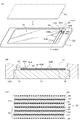
- FIG. 1 is a diagram showing a touch panel device according to an embodiment of the present invention, in which (A) is an external perspective view of the entire touch panel device viewed from the back side, and (B) is the (A) line # A- # A. A sectional view taken along the line and viewed in the direction of the arrow, (C) is a sectional view showing an example of a laminated structure of piezoelectric elements. It is sectional drawing explaining operation
- the piezoelectric vibration generator according to an embodiment of the present invention is applied to, for example, a force feedback touch panel device.
- a touch panel device 10 includes a touch panel (support substrate) 16, and the periphery of the touch panel 16 is a receiving portion provided in a hollow portion 14 of a frame 12. 15 is supported.
- a piezoelectric vibration element 20 is bonded to the back surface of the touch panel 16 along the short direction.
- One main surface of the piezoelectric vibration element 20 is bonded to the back surface of the touch panel 16 via the elastic body 18. By directly joining the entire main surface of the piezoelectric vibration element 20 to the touch panel 16, the impact resistance of the touch panel 16 may be improved.
- the formation position of the piezoelectric vibration element 20 is not limited to that shown in FIG. 1 and can be changed as appropriate.
- the frame 12 is made of, for example, an aluminum alloy.
- the touch panel 16 is configured, for example, by overlaying a transparent electrode such as a transparent conductive film (ITO) (not shown) on polycarbonate resin or quartz glass.
- the elastic body 18 is made of an elastic member such as polyurethane or EPDM (ethylene propylene rubber), but is not limited thereto.
- Tensile modulus measured according to JIS K7161 of elastic body 18 (hereinafter referred to simply as “elastic modulus” refers to the tensile modulus measured according to JIS K7161 unless otherwise stated in context) Is less than 20 MPa, the vibration of the piezoelectric vibration element 20 is difficult to be transmitted to the touch panel 16, and conversely, when the elastic modulus is greater than 100 MPa, the rigidity and tensile force when a compression force is applied to the elastic body 18. The difference from the rigidity when adding is reduced, and the vibration of the piezoelectric vibration element 20 cannot be asymmetrically transmitted to the touch panel 16 side as will be described later.
- the elastic modulus of the elastic body 18 is set in the range of 20 to 100 MPa.
- the elastic body 18 is configured to have a thickness of 50 to 160 ⁇ m. If the thickness of the elastic body 18 is less than 50 ⁇ m, it becomes difficult for the operator to sense the elastic displacement of the elastic body 18, and as a result, a sufficient click feeling described later cannot be obtained. On the other hand, if the thickness is larger than 160 ⁇ m, the vibration of the piezoelectric vibration element 20 is not easily transmitted to the touch panel 16.
- an epoxy-based, acrylic-based, or silicone-based adhesive has a thickness of about 20 to 50 ⁇ m, for example. It is applied as follows.
- the piezoelectric vibration element 20 is a bimorph type piezoelectric vibration element. As shown in FIG. 1C, the piezoelectric vibration element 20 includes a piezoelectric element 22 and a piezoelectric element 24, and each of the piezoelectric element 22 and the piezoelectric element 24 is formed by laminating a piezoelectric layer 28 and an electrode layer 30. The piezoelectric element 22 and the piezoelectric element 24 are stacked with an electrode layer 26 interposed therebetween.
- the piezoelectric layer 28 is made of, for example, PZT-based piezoelectric ceramics, and the electrode layer 30 is made of, for example, silver.
- the number and thickness of the piezoelectric layers 28 and electrode layers 30 constituting the piezoelectric vibration element 20 are arbitrary and are not limited to those explicitly described in this specification.
- the piezoelectric layer 28 is configured so that the thickness of one layer is about 18 to 66 ⁇ m
- the piezoelectric element 22 and the piezoelectric element 24 are configured by stacking about 6 to 20 layers of the piezoelectric layer 28.
- the electrode layer 30 includes an electrode layer 30A and an electrode layer 30B that are separated from each other.
- the electrode layer 30 may be composed of a single member.
- a through hole (not shown) is formed inside the bimorph type piezoelectric vibration element 20, and the piezoelectric layers 28 are connected to each other through the through hole.
- a terminal board 34 is provided on the back surface of the touch panel 16.
- the terminal substrate 34 includes terminal electrodes 36A and 36B connected to the electrode layers 30A and 30B, respectively.
- the terminal substrate 34 is bonded to the touch panel 16 via a wiring protective layer 32 made of an elastic material.
- the terminal electrodes 36A and 36B are connected to the electrode layers 30A and 30B by wirings 38A and 38B.
- the wirings 38A and 38B are formed by, for example, a conductive paste. Since the wirings 38A and 38B are formed on the wiring protective layer 32 made of an elastic body, the wirings 38A and 38B can move following the vibration of the piezoelectric vibration element 20 and thus are not easily disconnected.
- the wiring protective layer 32 is made of, for example, urethane resin, like the elastic body 18. By forming the wiring protective layer 32 from the same material as that of the elastic body 18, the bonding strength between the two can be improved.
- a back panel 40 for displaying various information and the like is provided on the back surface of the touch panel 16.
- the back panel 40 is provided on the touch panel 16 so as to seal the hollow portion 14 of the frame 12.
- a speaker element may be provided in the sealed hollow portion 14 of the touch panel device 10.
- the touch panel device 10 includes a known operation position detection mechanism that detects a position where the pressure is applied when a pressure is applied to the touch panel 16. Further, the touch panel device 10 includes a drive circuit (not shown) that applies a drive voltage for vibrating the piezoelectric vibration element 20 when the user presses the touch panel 16.
- the drive circuit is connected to the electrode layers 30A and 30B of the piezoelectric vibration element 20 via terminal electrodes 36A and 36B of the terminal substrate 34 and wirings 38A and 38B.
- FIG. 2 is a cross-sectional view showing a part of the touch panel device 10, and the touch panel device 10 is turned upside down from FIG.
- FIG. 2A shows a state in which no driving voltage is supplied to the electrode layers 30 ⁇ / b> A and 30 ⁇ / b> B of the touch panel device 10.
- an AC driving voltage is applied to the electrode layers 30A and 30B via the terminal electrodes 36A and 36B and the wirings 38A and 38B from a driving circuit (not shown)
- the piezoelectric vibration element 20 is opposite to the touch panel 16 (FIG.
- FIG. 2B shows a state in which the piezoelectric vibration element 20 is at a position intermediate between the position shown in FIG. 2B and the position shown in FIG.
- an external force in the pulling direction acts on the elastic body 18 to reduce the rigidity of the elastic body 18.
- the piezoelectric vibration element 20 is on the same side as the touch panel 16.
- the elastic body 18 is compressed to increase the rigidity of the elastic body 18. Accordingly, when the piezoelectric vibration element 20 is displaced to the same side as the touch panel 16, the displacement of the piezoelectric vibration element 20 is more easily transmitted to the touch panel 16 than when the piezoelectric vibration element 20 is displaced to the opposite side. Can be displaced more greatly. As a result, it is possible to reliably give a click feeling to the fingertip of the user who operates the touch panel 16. As described above, although the piezoelectric vibration element 20 vibrates symmetrically in the vertical direction, the displacement of the piezoelectric vibration element 20 toward the touch panel 16 is more greatly felt for the user.
- Rigidity indicates the difficulty of deformation of a structural member, and is generally given by the product of the cross-sectional shape (elastic second moment) of the member and the elastic modulus of the material (see, for example, “Plastic Dictionary” Industrial Research Committee) .
- the rigidity of the elastic body is generally low when receiving a tensile force (when deforming in the pulling direction) and is high when receiving a compressive force (when deforming in the compressing direction). Due to the properties of this elastic body, the rigidity of the elastic body 18 is lowered when the piezoelectric vibration element 20 is displaced in the opposite direction of the touch panel 16, and conversely, the elastic body 18 is elastic when the piezoelectric vibration element 20 is displaced in the direction of the touch panel 16.
- the rigidity of the body 18 is increased. As a result, the displacement of the piezoelectric vibration element 20 in the direction toward the touch panel 16 is more easily transmitted than the displacement in the direction of leaving, and the displacement of the piezoelectric vibration element 20 is transmitted to the touch panel 16 asymmetrically.
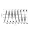
- FIG. 3 illustrates a touch panel using PZT piezoelectric ceramics (thickness 0.2 mm, using silver electrodes) as the piezoelectric vibration element 20, and urethane resin (thickness 0.16 mm) as the elastic body 18 and the wiring protection layer 32.
- PZT piezoelectric ceramics thickness 0.2 mm, using silver electrodes
- urethane resin thickness 0.16 mm
- FIG. 3 illustrates a touch panel using PZT piezoelectric ceramics (thickness 0.2 mm, using silver electrodes) as the piezoelectric vibration element 20, and urethane resin (thickness 0.16 mm) as the elastic body 18 and the wiring protection layer 32.
- urethane resin thickness 0.16 mm
- the present invention is not limited to the above-described embodiments, and various modifications can be made without departing from the gist of the present invention.
- the shape, dimensions, and materials shown in this specification are examples, and can be changed as necessary.
- the present invention can be used for a piezoelectric vibration device such as a force feedback touch panel.
- Touch panel device 12 Frame 12A: Front surface 12B: Back surface 14: Hollow portion 15: Receiving portion 16: Touch panel (support substrate) 18: Elastic body 20: Piezoelectric vibration element 22, 24: Piezoelectric elements 26, 30, 30A, 30B: Electrode layer 28: Piezoelectric layer 32: Wiring protective layer 34: Terminal substrate 36A, 36B: Terminal electrodes 38A, 38B: Wiring 40 : Back panel
Landscapes
- Engineering & Computer Science (AREA)
- General Engineering & Computer Science (AREA)
- Theoretical Computer Science (AREA)
- Human Computer Interaction (AREA)
- Physics & Mathematics (AREA)
- General Physics & Mathematics (AREA)
- Mechanical Engineering (AREA)
- Position Input By Displaying (AREA)
Abstract
Description
12:フレーム
12A:表面
12B:裏面
14:中空部
15:受け部
16:タッチパネル(支持基板)
18:弾性体
20:圧電振動素子
22,24:圧電素子
26,30,30A,30B:電極層
28:圧電層
32:配線保護層
34:端子基板
36A,36B:端子電極
38A,38B:配線
40:背面パネル
Claims (5)
- 支持基板と、該支持基板を振動させる圧電振動素子とを有する圧電振動装置であって、
前記圧電振動素子はバイモルフ型であり、
前記圧電振動素子の一方の主面の全面が、JIS K7161に準じて測定した引張弾性率20~100MPaの弾性体を介して、前記支持基板と接合している圧電振動装置。 - 前記弾性体の厚みが、50~160μmである請求項1記載の圧電振動装置。
- 前記支持基板に、前記圧電振動素子が接合される面と同一の面に設けられており、端子電極を有する端子基板と、
該端子基板の端子電極と、前記圧電振動素子の電極とを接続する配線と、
該配線と前記支持基板の間に設けられており、弾性体によって形成された配線保護層と、
を有する請求項1又は2記載の圧電振動装置。 - 前記支持基板と圧電振動素子間に介在させる前記弾性体と、前記配線保護層とが、同じ材質により形成されている請求項3記載の圧電振動装置。
- 支持基板と、
該支持基板を振動させるバイモルフ型の圧電振動素子と、
前記支持基板を支持するフレームと、
前記支持基板の背面側に設けられた情報を表示する表示部と、
前記支持基板に対する使用者の接触動作に対応して、前記圧電振動素子を駆動する駆動手段と、を備え、
前記圧電振動素子の一方の主面が、JIS K7161に準じて測定した引張弾性率20~100MPaの弾性体を介して、前記支持基板と接合しているタッチパネル装置。
Priority Applications (4)
| Application Number | Priority Date | Filing Date | Title |
|---|---|---|---|
| KR1020137012562A KR101442014B1 (ko) | 2010-12-28 | 2011-12-26 | 압전 진동 장치 및 터치패널 장치 |
| US13/995,616 US9196816B2 (en) | 2010-12-28 | 2011-12-26 | Piezoelectric oscillation device with elastic body and touch panel having same |
| JP2012550916A JP5558589B2 (ja) | 2010-12-28 | 2011-12-26 | タッチパネル装置 |
| CN201180063676.XA CN103282865B (zh) | 2010-12-28 | 2011-12-26 | 压电振动装置和触摸面板装置 |
Applications Claiming Priority (2)
| Application Number | Priority Date | Filing Date | Title |
|---|---|---|---|
| JP2010293779 | 2010-12-28 | ||
| JP2010-293779 | 2010-12-28 |
Publications (1)
| Publication Number | Publication Date |
|---|---|
| WO2012090893A1 true WO2012090893A1 (ja) | 2012-07-05 |
Family
ID=46382997
Family Applications (1)
| Application Number | Title | Priority Date | Filing Date |
|---|---|---|---|
| PCT/JP2011/079989 Ceased WO2012090893A1 (ja) | 2010-12-28 | 2011-12-26 | 圧電振動装置及びタッチパネル装置 |
Country Status (5)
| Country | Link |
|---|---|
| US (1) | US9196816B2 (ja) |
| JP (1) | JP5558589B2 (ja) |
| KR (1) | KR101442014B1 (ja) |
| CN (1) | CN103282865B (ja) |
| WO (1) | WO2012090893A1 (ja) |
Cited By (1)
| Publication number | Priority date | Publication date | Assignee | Title |
|---|---|---|---|---|
| JP2018124908A (ja) * | 2017-02-03 | 2018-08-09 | 株式会社デンソーテン | 制御装置、入力システムおよび制御方法 |
Families Citing this family (7)
| Publication number | Priority date | Publication date | Assignee | Title |
|---|---|---|---|---|
| CN103703795B (zh) * | 2011-10-03 | 2017-06-13 | 京瓷株式会社 | 压电振动装置及使用其的便携式终端 |
| CN105452993A (zh) * | 2014-01-16 | 2016-03-30 | 志丰电子股份有限公司 | 面板触控回馈振动装置 |
| JP6825404B2 (ja) * | 2017-02-13 | 2021-02-03 | Tdk株式会社 | 振動デバイス |
| JP7235224B2 (ja) * | 2018-02-26 | 2023-03-08 | 太陽誘電株式会社 | 振動発生装置 |
| JP7268477B2 (ja) * | 2019-05-20 | 2023-05-08 | Tdk株式会社 | 音響デバイス |
| KR102709306B1 (ko) * | 2019-07-10 | 2024-09-24 | 삼성디스플레이 주식회사 | 표시 장치 |
| WO2021177268A1 (ja) * | 2020-03-06 | 2021-09-10 | 株式会社村田製作所 | 振動装置 |
Citations (5)
| Publication number | Priority date | Publication date | Assignee | Title |
|---|---|---|---|---|
| JP2005045691A (ja) * | 2003-07-24 | 2005-02-17 | Taiyo Yuden Co Ltd | 圧電振動装置 |
| JP2008130055A (ja) * | 2006-11-27 | 2008-06-05 | Sony Corp | タッチパネルディスプレイ装置および駆動方法並びに電子機器 |
| JP2010108490A (ja) * | 2008-10-03 | 2010-05-13 | Daikin Ind Ltd | タッチパネルおよび透明圧電シート |
| JP2010146576A (ja) * | 2009-12-25 | 2010-07-01 | Sony Corp | 入力装置および電子機器 |
| JP2011175518A (ja) * | 2010-02-25 | 2011-09-08 | Kyocera Corp | タッチパネル装置 |
Family Cites Families (6)
| Publication number | Priority date | Publication date | Assignee | Title |
|---|---|---|---|---|
| JP3937982B2 (ja) | 2002-08-29 | 2007-06-27 | ソニー株式会社 | 入出力装置および入出力装置を有する電子機器 |
| JP4424729B2 (ja) | 2004-02-05 | 2010-03-03 | Smk株式会社 | タブレット装置 |
| JP4443962B2 (ja) * | 2004-03-17 | 2010-03-31 | 日東電工株式会社 | ダイシング・ダイボンドフィルム |
| JP2006048302A (ja) * | 2004-08-03 | 2006-02-16 | Sony Corp | 圧電複合装置、その製造方法、その取扱方法、その制御方法、入出力装置及び電子機器 |
| JP4628479B2 (ja) * | 2008-08-04 | 2011-02-09 | 日東電工株式会社 | ダイシング・ダイボンドフィルム |
| JP5561949B2 (ja) * | 2009-04-08 | 2014-07-30 | 日東電工株式会社 | 熱硬化型ダイボンドフィルム |
-
2011
- 2011-12-26 US US13/995,616 patent/US9196816B2/en active Active
- 2011-12-26 CN CN201180063676.XA patent/CN103282865B/zh active Active
- 2011-12-26 WO PCT/JP2011/079989 patent/WO2012090893A1/ja not_active Ceased
- 2011-12-26 JP JP2012550916A patent/JP5558589B2/ja active Active
- 2011-12-26 KR KR1020137012562A patent/KR101442014B1/ko active Active
Patent Citations (5)
| Publication number | Priority date | Publication date | Assignee | Title |
|---|---|---|---|---|
| JP2005045691A (ja) * | 2003-07-24 | 2005-02-17 | Taiyo Yuden Co Ltd | 圧電振動装置 |
| JP2008130055A (ja) * | 2006-11-27 | 2008-06-05 | Sony Corp | タッチパネルディスプレイ装置および駆動方法並びに電子機器 |
| JP2010108490A (ja) * | 2008-10-03 | 2010-05-13 | Daikin Ind Ltd | タッチパネルおよび透明圧電シート |
| JP2010146576A (ja) * | 2009-12-25 | 2010-07-01 | Sony Corp | 入力装置および電子機器 |
| JP2011175518A (ja) * | 2010-02-25 | 2011-09-08 | Kyocera Corp | タッチパネル装置 |
Cited By (1)
| Publication number | Priority date | Publication date | Assignee | Title |
|---|---|---|---|---|
| JP2018124908A (ja) * | 2017-02-03 | 2018-08-09 | 株式会社デンソーテン | 制御装置、入力システムおよび制御方法 |
Also Published As
| Publication number | Publication date |
|---|---|
| JP5558589B2 (ja) | 2014-07-23 |
| US9196816B2 (en) | 2015-11-24 |
| JPWO2012090893A1 (ja) | 2014-06-05 |
| CN103282865B (zh) | 2016-12-07 |
| KR20130080051A (ko) | 2013-07-11 |
| KR101442014B1 (ko) | 2014-09-18 |
| CN103282865A (zh) | 2013-09-04 |
| US20130271418A1 (en) | 2013-10-17 |
Similar Documents
| Publication | Publication Date | Title |
|---|---|---|
| JP5558589B2 (ja) | タッチパネル装置 | |
| EP3056977B1 (en) | Tactile sense presenting device | |
| US10664054B2 (en) | Vibrating device | |
| KR101601748B1 (ko) | 압전 액추에이터, 압전 진동 장치 및 휴대 단말 | |
| US10509470B2 (en) | Vibrating device | |
| KR102391894B1 (ko) | 압전 소자, 이 소자를 포함하는 압전 액츄에이터, 및 이 엑츄에이터를 포함하는 압전 모듈 | |
| WO2016063782A1 (ja) | 振動装置および触覚提示装置 | |
| JP5975185B2 (ja) | 触覚提示装置 | |
| JP5865963B2 (ja) | 圧電アクチュエータ、圧電振動装置および携帯端末 | |
| CN116419134B (zh) | 振动设备以及包括该振动设备的电子设备 | |
| JP6318970B2 (ja) | 振動体および触覚提示装置 | |
| JP2015186232A (ja) | 音響発生器およびこれを備えた音響発生装置、電子機器、携帯端末 | |
| US10572015B2 (en) | Vibrating device and tactile sense presenting device | |
| WO2017057656A1 (ja) | 振動装置および触覚提示装置 |
Legal Events
| Date | Code | Title | Description |
|---|---|---|---|
| 121 | Ep: the epo has been informed by wipo that ep was designated in this application |
Ref document number: 11853784 Country of ref document: EP Kind code of ref document: A1 |
|
| ENP | Entry into the national phase |
Ref document number: 20137012562 Country of ref document: KR Kind code of ref document: A |
|
| ENP | Entry into the national phase |
Ref document number: 2012550916 Country of ref document: JP Kind code of ref document: A |
|
| WWE | Wipo information: entry into national phase |
Ref document number: 13995616 Country of ref document: US |
|
| NENP | Non-entry into the national phase |
Ref country code: DE |
|
| 122 | Ep: pct application non-entry in european phase |
Ref document number: 11853784 Country of ref document: EP Kind code of ref document: A1 |