WO2012090664A1 - 充電装置 - Google Patents
充電装置 Download PDFInfo
- Publication number
- WO2012090664A1 WO2012090664A1 PCT/JP2011/078312 JP2011078312W WO2012090664A1 WO 2012090664 A1 WO2012090664 A1 WO 2012090664A1 JP 2011078312 W JP2011078312 W JP 2011078312W WO 2012090664 A1 WO2012090664 A1 WO 2012090664A1
- Authority
- WO
- WIPO (PCT)
- Prior art keywords
- battery
- charging
- condition
- charged
- information
- Prior art date
Links
Images


Classifications
-
- H—ELECTRICITY
- H01—ELECTRIC ELEMENTS
- H01M—PROCESSES OR MEANS, e.g. BATTERIES, FOR THE DIRECT CONVERSION OF CHEMICAL ENERGY INTO ELECTRICAL ENERGY
- H01M10/00—Secondary cells; Manufacture thereof
- H01M10/42—Methods or arrangements for servicing or maintenance of secondary cells or secondary half-cells
- H01M10/44—Methods for charging or discharging
- H01M10/443—Methods for charging or discharging in response to temperature
-
- H—ELECTRICITY
- H01—ELECTRIC ELEMENTS
- H01M—PROCESSES OR MEANS, e.g. BATTERIES, FOR THE DIRECT CONVERSION OF CHEMICAL ENERGY INTO ELECTRICAL ENERGY
- H01M10/00—Secondary cells; Manufacture thereof
- H01M10/42—Methods or arrangements for servicing or maintenance of secondary cells or secondary half-cells
- H01M10/48—Accumulators combined with arrangements for measuring, testing or indicating the condition of cells, e.g. the level or density of the electrolyte
-
- H—ELECTRICITY
- H02—GENERATION; CONVERSION OR DISTRIBUTION OF ELECTRIC POWER
- H02J—CIRCUIT ARRANGEMENTS OR SYSTEMS FOR SUPPLYING OR DISTRIBUTING ELECTRIC POWER; SYSTEMS FOR STORING ELECTRIC ENERGY
- H02J7/00—Circuit arrangements for charging or depolarising batteries or for supplying loads from batteries
- H02J7/0029—Circuit arrangements for charging or depolarising batteries or for supplying loads from batteries with safety or protection devices or circuits
-
- H—ELECTRICITY
- H02—GENERATION; CONVERSION OR DISTRIBUTION OF ELECTRIC POWER
- H02J—CIRCUIT ARRANGEMENTS OR SYSTEMS FOR SUPPLYING OR DISTRIBUTING ELECTRIC POWER; SYSTEMS FOR STORING ELECTRIC ENERGY
- H02J7/00—Circuit arrangements for charging or depolarising batteries or for supplying loads from batteries
- H02J7/007—Regulation of charging or discharging current or voltage
- H02J7/007188—Regulation of charging or discharging current or voltage the charge cycle being controlled or terminated in response to non-electric parameters
- H02J7/007192—Regulation of charging or discharging current or voltage the charge cycle being controlled or terminated in response to non-electric parameters in response to temperature
- H02J7/007194—Regulation of charging or discharging current or voltage the charge cycle being controlled or terminated in response to non-electric parameters in response to temperature of the battery
-
- H—ELECTRICITY
- H01—ELECTRIC ELEMENTS
- H01M—PROCESSES OR MEANS, e.g. BATTERIES, FOR THE DIRECT CONVERSION OF CHEMICAL ENERGY INTO ELECTRICAL ENERGY
- H01M10/00—Secondary cells; Manufacture thereof
- H01M10/42—Methods or arrangements for servicing or maintenance of secondary cells or secondary half-cells
- H01M10/46—Accumulators structurally combined with charging apparatus
-
- H—ELECTRICITY
- H01—ELECTRIC ELEMENTS
- H01M—PROCESSES OR MEANS, e.g. BATTERIES, FOR THE DIRECT CONVERSION OF CHEMICAL ENERGY INTO ELECTRICAL ENERGY
- H01M10/00—Secondary cells; Manufacture thereof
- H01M10/42—Methods or arrangements for servicing or maintenance of secondary cells or secondary half-cells
- H01M10/48—Accumulators combined with arrangements for measuring, testing or indicating the condition of cells, e.g. the level or density of the electrolyte
- H01M10/486—Accumulators combined with arrangements for measuring, testing or indicating the condition of cells, e.g. the level or density of the electrolyte for measuring temperature
-
- Y—GENERAL TAGGING OF NEW TECHNOLOGICAL DEVELOPMENTS; GENERAL TAGGING OF CROSS-SECTIONAL TECHNOLOGIES SPANNING OVER SEVERAL SECTIONS OF THE IPC; TECHNICAL SUBJECTS COVERED BY FORMER USPC CROSS-REFERENCE ART COLLECTIONS [XRACs] AND DIGESTS
- Y02—TECHNOLOGIES OR APPLICATIONS FOR MITIGATION OR ADAPTATION AGAINST CLIMATE CHANGE
- Y02E—REDUCTION OF GREENHOUSE GAS [GHG] EMISSIONS, RELATED TO ENERGY GENERATION, TRANSMISSION OR DISTRIBUTION
- Y02E60/00—Enabling technologies; Technologies with a potential or indirect contribution to GHG emissions mitigation
- Y02E60/10—Energy storage using batteries
Definitions
- the present invention relates to a battery charger having a function of confirming normal operation of a battery protection circuit during charging.
- a charging device is provided with a controller for acquiring various information such as temperature from a battery and controlling charging based on the acquired information.
- a protection circuit that stops charging current based on information from the battery without going through the controller is provided separately from the controller in case the controller fails and charging control is not performed normally. There is something that is.
- a charging device with high reliability during charging is provided.
- the invention made in order to solve the problem described in “Problem to be Solved by the Invention” is a charging device for charging a battery for an electric tool, and includes a control unit, a charge detection unit, and a charge stop unit. And a diagnostic unit.
- the control unit acquires information indicating the state of the battery from the battery, and controls permission or prohibition of charging the battery depending on whether the acquired information satisfies a predetermined first condition.
- the charge detection unit detects a charging current to the battery.
- the charging stop unit acquires information indicating the state of the battery from the battery, and when the acquired information satisfies a predetermined second condition, the charging unit is independent of charging permission or prohibition control by the control unit. The charging to the battery is stopped.
- the diagnostic unit inputs diagnostic information satisfying the second condition to the charging stop unit in addition to or instead of information indicating the state of the battery based on information input from the control unit.
- control unit stops the charging of the battery via the charging stop unit by outputting diagnostic information satisfying the second condition to the diagnostic unit in a state where the charging of the battery is permitted. Then, it is acquired whether or not the battery is charged from the charge detection unit, and when the battery is not charged, the diagnosis information that satisfies the second condition for the diagnosis unit is stopped, and the battery is charged. If the battery is charged, charging the battery is prohibited.
- the reliability at the time of battery charging can be increased. This will be described below.
- diagnostic information that satisfies a predetermined second condition is input to the charging stop unit.
- the “predetermined second condition” means, for example, a voltage value exceeding the upper limit value of the charging voltage of the battery, a temperature value exceeding the temperature at the time of full charging of the battery, or failure of the battery. This means a condition for prohibiting charging of the battery, such as information indicating.
- the charging device in particular, the charging stop unit is normal, a predetermined second condition is satisfied in addition to or instead of the information indicating the state of the battery while charging the battery is permitted.
- diagnosis information is input to the charging stop unit, the battery is not charged.
- the charging detection unit acquires whether or not the battery is charged. If it is normal and charged, it turns out that the said charging device is abnormal.
- the “information indicating the state of the battery” means, for example, information regarding the amount of charge of the battery such as the temperature and charging voltage of the battery, and the state in which the battery can be charged, such as whether the battery is normal or abnormal It is information indicating whether or not.
- the “predetermined first condition” means an upper limit value of the temperature at which the battery can be charged, and is a value that varies depending on the type of the battery to be charged.
- the “predetermined second condition” described above also has a different value depending on the type of the battery to be charged.
- the temperature of the battery is used as information indicating the state of the battery
- the predetermined first condition is an upper limit value of the temperature at which the battery can be charged
- the predetermined second condition is It is preferable that the temperature be higher than a temperature obtained by adding a specified value to the upper limit value of the temperature at which the battery can be charged.
- the temperature is suitable as information indicating the charging state of the NiMH battery or NiCd battery, and is therefore suitable for protecting the charging device when charging the NiMH battery or NiCd battery.
- the charging voltage of the battery is used as information indicating the state of the battery
- the predetermined first condition is set as the upper limit value of the charging voltage with which the battery can be charged
- the battery can be charged until it is fully charged, and self-diagnosis is performed with a voltage (predetermined second condition) exceeding the upper limit of the fully charged voltage (predetermined first condition).
- the charging device can be reliably protected.
- the charging voltage is suitable as information indicating the state of charge of the Li ion battery, it is suitable for protecting the charging device when charging the Li ion battery.
- digital data indicating either “permitted” or “stopped” charging of the battery is used as information indicating the state of the battery, and the predetermined first condition and the predetermined Both of the second conditions are preferably digital data indicating that the charging of the battery is stopped.
- charge control and self-diagnosis can be performed based on information indicating normality or abnormality of the battery, in addition to using the temperature and charging voltage indicating the charging state of the battery as digital data.
- the self-diagnosis of the charging device is performed at various timings.
- a battery insertion detection unit that detects that the battery has been inserted is provided, and the control unit is charged after the battery insertion detection is detected by the battery insertion detection unit. It is preferable to execute the self-diagnosis process before the operation is started. This corresponds to the fifth aspect of the present invention.
- a battery insertion detection unit that detects that the battery has been inserted is provided, and the control unit detects insertion of the battery via the battery insertion detection unit and starts charging. Then, it is preferable to execute the self-diagnosis process when a predetermined self-diagnosis start condition is met.
- a predetermined self-diagnosis start condition means, for example, a case where a predetermined time has elapsed since the start of charging, or a case where the charge amount of the battery reaches a predetermined value.
- the amount of charge can also be detected by detecting the temperature or charging voltage of the battery, or by accumulating the charging current in the control unit using the charge detection unit.
- the control unit stops diagnosis information that satisfies the second condition for the diagnosis unit when the charge detection unit detects that the battery is not charged.
- the control unit In addition to starting charging the battery, outputting information indicating that the charging stop unit is normal to the outside, and if charging is detected, prohibiting charging the battery
- the information indicating that the charging stop unit is abnormal may be output to the outside.
- Power supply terminal 84 ... Noise filter, 86 ... Rectification smoothing circuit, 90 ... LED, 100 ... communication terminal, 102 ... temperature input terminal, 131 ... decode IC, 132 ... flip-flop, 133 ... resistor, 134 ... tra Register.
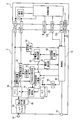
- FIG. 1 is a circuit diagram showing a schematic circuit configuration of a charging device 1 to which the present invention is applied
- FIG. 2 is a charge prohibition detection when the temperature of the battery 5 is used as information indicating the charging state of the battery 5.
- 3 is a circuit diagram of a circuit 30 and a self-diagnosis circuit 40.
- the charging device 1 is a charging device 1 for charging a battery 5 for an electric tool, and as shown in FIG. 1, a control unit 10, a current detection unit 20, a current detection element 22, a charge prohibition detection circuit 30, A self-diagnosis circuit 40, a voltage detection unit 60, a PWM output setting unit 70, a PWM control IC power supply 72, a PWM control IC 74, a main converter 80, a power supply terminal 82, a noise filter 84, a rectifying / smoothing circuit 86, an LED 90, and the like. Yes.
- the control unit 10 includes a CPU, a ROM, a RAM, and an I / O (not shown), acquires information indicating the state of the battery 5 from the battery 5, and determines whether the acquired information satisfies a predetermined first condition. In this case, permission or prohibition of charging the battery 5 is controlled.
- the “information indicating the state of the battery 5” is the temperature of the battery 5
- the “predetermined first condition” means an upper limit value of the temperature at which the battery 5 can be charged, The value varies depending on the type of the battery 5 to be charged.
- the current detection unit 20 is for detecting whether or not the battery 5 is being charged.
- the current detection element 22 arranged in series with the GND line. , The charging current output from the charging device 1 to the battery 5 is detected by the battery 5.
- the current detection element 22 is a shunt resistor that converts a current into a voltage and outputs the voltage.
- the charging prohibition detection circuit 30 acquires information (temperature) indicating the state of the battery 5 from the battery 5, and when the acquired temperature satisfies a predetermined second condition, the control unit 10 controls whether to permit or prohibit charging. Irrespectively stops charging the battery 5.
- the “predetermined second condition” is a temperature higher than a temperature obtained by adding a specified value to the upper limit value of the temperature at which the battery 5 can be charged, and depends on the type of the battery 5 to be charged. Different values.
- the specified value is a value of 0 or more.
- a voltage indicating the temperature of the battery 5 is input from the temperature input terminal 102, and the input voltage is a voltage indicating a fully charged state (predetermined (Second condition)
- a charge prohibition signal is output to the PWM control IC power supply 72.
- the charge prohibition detection circuit 30 includes two comparators 31, 32 and four resistors 33, 34, 35, 36 as shown in FIG.
- the output voltage of the temperature sensor is input from the temperature input terminal 102 to the minus terminal 31 a of the comparator 31.
- a reference voltage is input to the plus terminal 31 b of the comparator 31.
- This reference voltage is a voltage having a value obtained by dividing the power supply voltage Vcc by the resistor 33 and the resistor 34.
- the reference voltage is a temperature obtained by adding a specified value to the temperature when the battery 5 is fully charged, that is, a value of a predetermined second condition. Voltage.
- the output of the comparator 31 is at the Lo (low) level. Conversely, if the battery 5 is further charged from the fully charged state due to a circuit failure or the like, the output voltage of the temperature sensor becomes lower than the reference voltage, and the output of the comparator 31 becomes high impedance. A Hi (high) level signal is input to the terminal 32 a via the resistor 36.
- the same reference voltage as the reference voltage input to the positive terminal 31 b of the comparator 31 is input to the positive terminal 32 b of the comparator 32. Further, the output voltage of the comparator 31 is input to the minus terminal 32a. That is, when the output voltage of the temperature sensor is higher than the reference voltage (when the temperature of the battery 5 is low), a Lo level signal is input. Therefore, the output of the comparator 32 becomes high impedance.
- the self-diagnosis circuit 40 adds diagnostic information satisfying a predetermined second condition (voltage lower than the reference voltage) based on information input from the control unit 10 to information indicating the state of the battery 5 and charging prohibition detection circuit 30. It is a circuit to input to.
- the transistor 41 comprises a transistor 41 and three resistors 42, 43, and 44.
- the transistor 41 is a bipolar NPN transistor, and its base is connected to the control unit 10 via a resistor 42.
- the collector is connected to the negative terminal 31a of the comparator 31 of the charge prohibition detection circuit 30 via the resistor 43, and is input to the negative terminal 31a in parallel with the temperature sensor output of the battery 5.
- the emitter is connected to GND.
- a resistor 44 is connected between the base and the emitter.
- the situation is the same as when the output voltage of the temperature sensor of the battery 5 is lowered, in other words, the situation where the temperature of the battery 5 is a temperature added with a specified value than when the battery 5 is fully charged. That is, an input that satisfies a predetermined second condition is made.
- the control unit 10 also performs self-diagnosis processing with the contents shown in the following (A) to (G).
- the voltage detection unit 60 is a voltmeter that is connected in parallel to the output line of the main converter 80, measures the charging voltage (the output voltage of the main converter 80) when charging the battery 5, and outputs it to the control unit 10.
- the PWM output setting unit 70 sets a duty ratio and the like in the PWM control IC 74 according to a command from the control unit 10.
- the PWM control IC power supply 72 receives a charge or charge prohibition signal from the control unit 10 or the charge prohibition detection circuit 30, and turns on (charges) or turns off (when charge is prohibited) the drive power supply of the PWM control IC 74. .
- the PWM control IC 74 is an IC that controls the PWM (Pulse Width Modulation. Pulse width modulation) of the main converter 80, and receives a command from the PWM output setting unit 70 to change the duty ratio of the PWM.
- PWM Pulse Width Modulation. Pulse width modulation
- the main converter 80 is a converter that converts the power supply voltage input from the power supply terminal 82 and rectified to direct current by the rectifying and smoothing circuit 86 through the noise filter 84 into direct current of the charging voltage of the battery 5.
- the LED 90 is a notification device that displays normality / abnormality of the charging device 1.
- the LED 90 emits green or red light, and when abnormal, the red and green light is emitted alternately.
- FIG. 3 is a flowchart showing the flow of the self-diagnosis process.
- the self-diagnosis process is stored in the ROM as a program, and the CPU reads out from the ROM and starts executing as soon as the charging device 1 is turned on.
- the CPU acquires the insertion and state of the battery 5.
- the CPU determines whether or not the state of the battery 5 acquired in S100 is charging permission. If it is determined that charging is permitted (Yes in S105), the process proceeds to S110. If it is determined that charging is prohibited (No in S105), the process returns to S100. It will be in a standby state until the battery 5 is inserted and charging is permitted.
- the CPU prohibits the output to the PWM control IC power supply 72, permits the output to the PWM output setting unit 70, and permits the output to the self-diagnosis circuit 40 (Lo level).
- the CPU determines whether or not the charging current is equal to or greater than a specified value. That is, a charging current value is acquired from the current detection unit 20, and it is determined whether or not the acquired charging current value is equal to or greater than a specified value.
- the process proceeds to S120. If it is determined that the charging current is equal to or greater than the specified value (Yes in S115), the process proceeds to S125. To do.
- the “specified value” is a current value necessary for determining whether or not charging is being performed, and may be determined in consideration of the type of the battery 5, the noise level, and the like.
- the CPU permits output to the PWM control IC power supply 72, prohibits output to the PWM output setting unit 70, and permits output to the self-diagnosis circuit 40 (Lo level).
- the CPU displays an error. That is, the LED 90 causes the red and green to emit light alternately to display an error, and then the process proceeds to S150.
- the CPU determines whether or not the charging current is equal to or greater than a specified value. If it is determined that the charging current is less than the specified value (No in S130), the process proceeds to S135. If it is determined that the charging current is equal to or greater than the specified value (Yes in S115), the process proceeds to S140. To do.
- the CPU permits output to the PWM control IC power supply 72, permits output to the PWM output setting unit 70, and prohibits output to the self-diagnosis circuit 40 (Hi level).
- the CPU displays an error. That is, the LED 90 causes the red and green to emit light alternately to display an error, and then the process proceeds to S150.
- the CPU determines whether or not the charging current is equal to or greater than a specified value. If it is determined that the charging current is less than the specified value (No in S145), the process proceeds to S150. If it is determined that the charging current is equal to or greater than the specified value (Yes in S145), the process proceeds to S155. To do.
- the CPU displays an error. That is, the LED 90 is caused to emit light alternately in red and green to display an error, and then the process proceeds to S150.
- S150 the output to the PWM control IC power supply 72 is prohibited, the output to the PWM output setting unit 70 is prohibited, and the output to the self-diagnosis circuit 40 is prohibited (Hi level), and then the process ends.
- the charging device 1 is normal and if it is detected that the battery is charged. It turns out that charge is performed, and it turns out that the charging device 1 is abnormal.
- the charging of the battery 5 is started.
- the charging of the battery 5 is prohibited, so that the charging device 1, particularly the charging prohibition detection circuit 30 is broken. Since the battery 5 is not charged, the reliability of the charging device 1 when charging the battery 5 can be increased.
- the temperature of the battery 5 is used as information indicating the state of the battery 5, the predetermined first condition is set as an upper limit value of the temperature at which the battery 5 can be charged, and the predetermined second condition is set as an upper limit of the temperature at which the battery 5 can be charged.
- the temperature is higher than the temperature obtained by adding the specified value to the value.
- the battery 5 can be charged until it reaches a fully charged state, and at a temperature (predetermined second condition) that exceeds a temperature obtained by adding a specified value to the upper limit value (predetermined first condition) indicating the fully charged state. Since the self-diagnosis is performed, the charging device 1 can be reliably protected.
- the temperature is suitable as information indicating the charging state of the NiMH battery or NiCd battery, and is therefore suitable for protecting the charging device 1 when charging the NiMH battery or NiCd battery.
- the LED 90 indicates whether the charging prohibition detection circuit 30 is normal or abnormal, the user can know whether the charging device 1 is normal or abnormal. Therefore, the charging device 1 is convenient and easy to use.
- the charging device 1 of the first embodiment the charging voltage of the battery 5 input from the voltage detection unit 60 is used as the input of the charging prohibition detection circuit 30 instead of the output voltage of the temperature sensor from the temperature input terminal 102.
- the second embodiment will be described with reference to FIGS. 4 and 5.
- FIG. 4 is a circuit diagram showing a schematic circuit configuration of the charging device in the second embodiment
- FIG. 5 uses the charging voltage of the battery 5 as information indicating the charging state of the battery 5 in the second embodiment.
- FIG. 6 is a circuit diagram of a part of the charge prohibition detection circuit 30 and the self-diagnosis circuit 40 in the case of FIG.
- the charging device 2 in the second embodiment is similar to the configuration of the charging device 1 in the first embodiment, the same components are denoted by the same reference numerals and description thereof is omitted.
- the charging device 2 has a circuit configuration in which the charging voltage detected by the voltage detection unit 60 is input to the charging prohibition detection circuit 30.
- the voltage detection unit 60 is a voltmeter for measuring a voltage (charging voltage) applied to the charging terminal of the battery 5 when charging the battery 5, and the measured charging voltage is used as the charge prohibition detection circuit 30 and the control unit. 10 is output.
- the charge prohibition detection circuit 30 receives the charge voltage measured by the voltage detector 60 as information indicating the state of the battery 5.
- the “predetermined second condition” is a voltage higher than a voltage obtained by adding a specified value to the upper limit value of the charging voltage of the battery 5, and differs depending on the type of the battery 5 to be charged. Value.
- the charging voltage of the battery 5 is input, and the input voltage is equal to or higher than a voltage obtained by adding a specified value to the charging voltage indicating the fully charged state (predetermined second condition).
- a charge prohibition signal is output to the PWM control IC.
- the configuration of the charging prohibition detection circuit 30 is the same as that of the charging prohibition detection circuit 30 of the first embodiment, and the voltage input to the negative terminal 31a of the comparator 31 is a temperature as shown in FIG. The output voltage from the sensor is replaced by the charging voltage.
- the output of the comparator 31 becomes high impedance, and when the charging voltage is higher than the reference voltage, the output of the comparator 31 becomes Lo level.
- the transistor 41 of the self-diagnosis circuit 40 is a bipolar PNP transistor, and its base is connected to the control unit 10 via a resistor 42.
- the emitter is connected to the power source Vcc , and the collector is input to the negative terminal 31 a of the comparator 31 of the charge prohibition detection circuit 30 via the resistor 43 in parallel with the charging voltage from the voltage detection unit 60.
- the emitter and the base are connected via a resistor 44.
- the charging voltage of the battery 5 becomes a voltage higher than a voltage obtained by adding a specified value to the fully charged voltage. That is, an input that satisfies a predetermined second condition is made. In such a charging device 2, it becomes the same operation
- the charging voltage is used as information indicating the state of the battery 5
- the predetermined first condition is the upper limit value of the charging voltage that the battery 5 can charge
- the predetermined second condition is charged by the battery 5.
- the voltage is higher than the voltage obtained by adding the specified value to the upper limit of the possible charging voltage.
- the charging voltage rises and reaches the upper limit when the battery 5 is fully charged. Therefore, the battery 5 can be charged until it is fully charged, and self-diagnosis is performed with a voltage (predetermined second condition) that exceeds a voltage obtained by adding a specified value to the upper limit (predetermined first condition). Therefore, the charging device 2 can be reliably protected.
- the charging voltage is suitable as information indicating the charging state of the Li ion battery 5, and is therefore suitable for protecting the charging device 2 when charging the Li ion battery 5.
- the charging device 3 of the first embodiment a third embodiment in which the charge prohibition detection circuit 30 and the self-diagnosis circuit 40 are integrated will be described with reference to FIGS. 6 and 7.
- FIG. 6 is a circuit diagram showing a schematic circuit configuration of the charging device in the third embodiment, and FIG. 7 uses digital data from the battery 5 as information indicating the charging state of the battery 5 in the third embodiment.
- FIG. 6 is a circuit diagram of a portion of a charge prohibition detection circuit 30 and a self-diagnosis circuit 40 when there is a failure.
- the charging device 3 in 3rd Embodiment is similar to the structure of the charging device 1 in 1st Embodiment, the same code
- the charging device 3 includes a charging prohibition detection circuit 30 and a self-diagnosis circuit 40 that are integrated, and inputs information indicating the state of the battery 5 from the battery 5 to the charging prohibition detection circuit 30 and the control unit 10. Circuit configuration.
- the information indicating the state of the battery 5 is, for example, digital data indicating the normal or abnormal state of the battery 5 in addition to the digital value of the battery 5 temperature or charging voltage indicating the charging state of the battery 5.
- the charge prohibition detection circuit 30 includes a decode IC 131, a flip-flop 132, a resistor 133, and a transistor 134.
- Information (digital data) indicating the state of the battery 5 is input from the battery 5 to the decode IC 131 via the communication terminal 100.
- the decode IC 131 decodes the digital data input from the battery 5 and outputs it to the flip-flop 132 as S (set) and R (reset) signals. For example, when the battery 5 is in a chargeable state, charging information is input from the battery 5, a Lo level signal is output to the S terminal of the flip-flop 132, and a Hi level signal is output to the R terminal, and the battery 5 is fully charged. In this state, charging stop information is input from the battery 5, and a Hi level signal is output to the S terminal of the flip-flop 132 and a Lo level signal is output to the R terminal.
- the flip-flop 132 is a so-called RS flip-flop, and has an R terminal and an S terminal as input terminals and a Q terminal as an output terminal.
- a Hi level signal is input to the S terminal and a Lo level signal is input to the R terminal, a Hi level signal is output from the Q terminal.
- a Lo level signal is input to the S terminal and a Hi level signal is input to the R terminal, a Lo level signal is output from the Q terminal.
- the transistor 134 is a bipolar NPN transistor, the base is connected to the Q terminal of the flip-flop 132 via the resistor 133, the collector is connected to the PWM control IC power supply 72, and the emitter is connected to GND. Has been.
- a Hi level signal is input from the decode IC 131 to the S terminal of the flip-flop 132, a Lo level signal is input to the R terminal, and a Hi level signal is output from the Q terminal. Is output.
- a Hi level signal is input to the base of the transistor 134, and the transistor 134 is turned on. That is, the collector and the emitter are in a conductive state, and the PWM control IC power supply 72 stops outputting, that is, the PWM control IC power supply is turned off, and charging of the battery 5 is prohibited.
- a Lo level signal is input from the decoding IC 131 to the S terminal of the flip-flop 132, a Hi level signal is input to the R terminal, and a Lo level signal is input from the Q terminal. Is output.
- a Lo level signal is input to the base of the transistor 134, and the transistor 134 is turned off. That is, the collector and the emitter are cut off, and the PWM control IC power source 72 outputs power, that is, power is supplied to the PWM control IC, and the battery 5 is charged.
- the operation of the charging device 3 is the same as that of the charging device 1 in the first embodiment.
- (Characteristics of the charging device 3) digital data indicating whether charging of the battery 5 is permitted or stopped is used as information indicating the state of the battery 5, and both the predetermined first condition and the predetermined second condition are the battery. 5 is digital data indicating charging stop.
- charging control and self-diagnosis can be performed based on information indicating normality or abnormality of the battery 5 in addition to using the temperature and charging voltage indicating the charging state of the battery 5 as digital data.
- the self-diagnosis of the charging devices 1 to 3 is performed at the start of charging in the above embodiment, the self-diagnosis may be performed during the charging.
- the processes from S110 to S155 are executed at regular time intervals.
- the normality / abnormality of the charging device 1 is notified due to the difference in the light emission color of the LED 90, but an error notification by sound such as a buzzer or sound may be performed instead of the LED 90, You may use LED90 and the error alert
- a PWM signal is received in response to a signal or digital data that satisfies the predetermined second condition from the control unit 10.
- Any device capable of turning on / off the control IC power source 72 may be used, and for example, a relay or an electronic switch may be used.
- the comparator 32 has a function of inverting the output result of the comparator 31 and may be replaced with an FET or the like.
- the control unit 10 determines whether the battery 5 is inserted and whether to permit charging. However, for the purpose of reducing standby power, the charging start switch 50 shown in FIG. Good.
- charging is prohibited by stopping the PWM control IC power supply from the charging prohibition detection circuit 30.
- a switch is provided between the main converter 80 and the battery 5. The charging may be prohibited by turning off this switch.
- the self-diagnosis circuit 40 is connected in parallel to information such as the temperature from the battery, and the operation of the charge prohibition detection circuit 30 is confirmed.
- information from the battery may be temporarily disconnected from the charge prohibition circuit 30 and only the self-diagnosis circuit 40 may be connected to the charge prohibition detection circuit 30 to check the operation of the charge prohibition circuit 30.
- the self-diagnosis circuit 40 is provided separately from the control unit 10 in the above embodiment, a circuit configuration including the self-diagnosis circuit 40 in the control unit 10 may be employed.
Abstract
Description
前記バッテリへの充電を許可した状態で、前記バッテリの状態を示す情報に加えて又は代えて、所定の第2条件を満たす診断情報を前記充電停止部に入力する。
さらに、本発明の第4局面では、前記バッテリの状態を示す情報として前記バッテリの充電を「許可する」又は「停止する」のいずれかを示すディジタルデータを用い、所定の第1条件及び所定の第2条件は、共に、前記バッテリの充電停止を示すディジタルデータとすることが好ましい。
ところで、充電装置の自己診断は、種々のタイミングに行うことが考えられる。前記バッテリの充電開始前に行う場合には、前記バッテリが挿入されたことを検出するバッテリ挿入検出部を備え、前記制御部は、バッテリ挿入検出部で前記バッテリの挿入検出がされてから、充電が開始される前に自己診断処理を実行するようにすることが好ましい。これが本発明の第5局面に相当する。
また、本発明の第6局面では、前記バッテリが挿入されたことを検出するバッテリ挿入検出部を備え、前記制御部は、バッテリ挿入検出部を介して前記バッテリの挿入検出がされ、充電が開始された後、所定の自己診断開始条件となったときに、自己診断処理を実行するようにすることが好ましい。
[第1実施形態]
図1は、本発明が適用された充電装置1の概略の回路構成を示す回路図であり、図2は、バッテリ5の充電状態を示す情報としてバッテリ5の温度を用いた場合の充電禁止検出回路30及び自己診断回路40の部分の回路図である。
電流検出部20は、バッテリ5へ充電が行われているか否かを検出するためのものであり、メインコンバータ80の2本の出力ラインのうち、GNDラインに直列に配置された電流検出素子22の出力電圧を測定することにより、バッテリ5に充電装置1からバッテリ5へ出力される充電電流を検出する。なお、電流検出素子22は、電流を電圧に変換して出力するシャント抵抗などである。
コンパレータ31のマイナス端子31aに温度入力端子102から温度センサの出力電圧が入力される。また、コンパレータ31のプラス端子31bには、基準電圧が入力される。この基準電圧は、電源電圧Vccを抵抗33と抵抗34で分圧した値の電圧であり、バッテリ5の満充電時の温度に規定値を加えた温度、つまり、所定の第2条件の値の電圧となっている。
逆に、回路の故障等により、バッテリ5が満充電状態から更に充電されると、温度センサの出力電圧が基準電圧よりも低くなり、コンパレータ31の出力はハイインピーダンスとなるため、コンパレータ32のマイナス端子32aには、抵抗36を介してHi(高)レベルの信号が入力される。
また、マイナス端子32aには、コンパレータ31の出力電圧が入力される。つまり、温度センサの出力電圧が基準電圧より高い場合(バッテリ5の温度が低い場合)には、Loレベルの信号が入力される。したがって、コンパレータ32の出力は、ハイインピーダンスとなる。
(A)バッテリ5が挿入されてから、充電が開始される前に自己診断処理を実行する。
(B)バッテリ5への充電を許可した状態で、第2条件を満たす診断情報を、自己診断回路40に出力することにより、充電禁止検出回路30を介してバッテリ5への充電を停止させる。
(D)電流検出部20から取得した充電電流が規定値未満の場合に、自己診断回路40に対する第2条件を満たす診断情報を停止して、バッテリ5への充電を開始する。
(F)電流検出部20から取得した充電電流が規定値以上の場合には、バッテリ5への充電を禁止する。
電圧検出部60は、メインコンバータ80の出力ラインに並列に接続され、バッテリ5を充電する際の充電電圧(メインコンバータ80の出力電圧)を測定し制御部10へ出力する電圧計である。
PWM制御用IC電源72は、制御部10又は充電禁止検出回路30からの充電又は充電禁止の信号を受け、PWM制御用IC74の駆動用電源をオン(充電時)又はオフ(充電禁止時)する。
(充電装置1の作動)
次に、図3に基づいて、制御部10で実行される自己診断処理について説明する。図3は、自己診断処理の流れを示すフローチャートである。
処理が開始されると、図3に示すように、S100において、CPUが、バッテリ5の挿入及び状態を取得する。
続くS115では、CPUが、充電電流が規定値以上であるか否かを判定する。つまり、電流検出部20から充電電流値を取得し、取得した充電電流値が規定値以上であるか否かを判定する。
S120では、CPUが、PWM制御用IC電源72への出力を許可、PWM出力設定部70への出力を禁止とし、自己診断回路40への出力を許可(Loレベル)とする。
S130では、CPUが、充電電流が規定値以上であるか否かを判定する。そして、充電電流が規定値未満であると判定した場合(S130においてNo)、処理をS135へ移行し、充電電流が規定値以上であると判定した場合(S115においてYes)、処理をS140へ移行する。
S140では、CPUがエラー表示を行わせる。つまり、LED90を赤色と緑色を交互に発光させてエラー表示を行わせた後、S150へ移行する。
S150では、PWM制御用IC電源72への出力を禁止、PWM出力設定部70への出力を禁止とし、自己診断回路40への出力を禁止(Hiレベル)とした後、処理を終了する。
このような、充電装置1によれば、バッテリ5への充電を許可した状態で、バッテリ5の温度に加えて、満充電時の温度に規定値を加えた温度以上の温度(所定の第2条件)を充電禁止検出回路30に入力している。
[第2実施形態]
次に、第1実施形態の充電装置1において、充電禁止検出回路30の入力を、温度入力端子102からの温度センサの出力電圧の代わりに、電圧検出部60から入力されるバッテリ5の充電電圧とした第2実施形態について、図4及び図5に基づいて説明する。
充電装置2は、図4に示すように、電圧検出部60で検出した充電電圧を充電禁止検出回路30に入力する回路構成となっている。
第2実施形態の場合、「所定の第2条件」とは、バッテリ5の充電電圧の上限値に規定値を加えた電圧よりも高い電圧であり、充電の対象となるバッテリ5の種類によって異なる値となる。
また、エミッタが電源Vccに接続され、コレクタが抵抗43を介して充電禁止検出回路30のコンパレータ31のマイナス端子31aに、電圧検出部60からの充電電圧と並列に入力されている。また、エミッタとベースとの間は、抵抗44を介して接続されている。
このような充電装置2では、第1実施形態における充電装置1と同じ作動となる。
このような充電装置2では、バッテリ5の状態を示す情報として充電電圧を用い、所定の第1条件をバッテリ5が充電可能な充電電圧の上限値とし、所定の第2条件をバッテリ5が充電可能な充電電圧の上限値に規定値を加えた電圧よりも高い電圧としている。
[第3実施形態]
次に、第1実施形態の充電装置3において、充電禁止検出回路30と自己診断回路40とを一体化した第3実施形態について図6及び図7に基づいて説明する。
充電装置3は、図6に示すように、充電禁止検出回路30と自己診断回路40とが一体化され、バッテリ5の状態を示す情報をバッテリ5から充電禁止検出回路30と制御部10に入力する回路構成となっている。
デコードIC131には、バッテリ5から通信端子100を介して、バッテリ5の状態を示す情報(ディジタルデータ)が入力される。
例えば、バッテリ5が充電可能状態になった場合には、バッテリ5から充電情報を入力し、フリップフロップ132のS端子にLoレベル、R端子にHiレベルの信号を出力し、バッテリ5が満充電状態になった場合には、バッテリ5から充電停止情報を入力し、フリップフロップ132のS端子にHiレベル、R端子にLoレベルの信号を出力する。
そして、S端子にHiレベル、R端子にLoレベルの信号が入力されるとQ端子からHiレベルの信号が出力される。また、S端子にLoレベル、R端子にHiレベルの信号が入力されると、Q端子からLoレベルの信号が出力される。
充電装置3の作動は、第1実施形態における充電装置1と同じである。
(充電装置3の特徴)
このような充電装置3では、バッテリ5の状態を示す情報としてバッテリ5の充電を許可又は停止のいずれかを示すディジタルデータを用い、所定の第1条件及び所定の第2条件は、共に、バッテリ5の充電停止を示すディジタルデータとしている。
[その他の実施形態]
以上、本発明の実施形態について説明したが、本発明は、以上に述べた実施形態に限定されるものではなく、種々の態様を採ることができる。
例えば、自己診断処理とは別タスクにおいて、一定時間間隔でS110からS155の処理を実行するのである。
(5)上記実施形態では、バッテリ5の挿入及び充電許可の判断を制御部10で行なっているが、待機電力削減の目的で、図1の充電開始スイッチ50を設けて充電開始のトリガとしてもよい。
Claims (7)
- 電動工具用のバッテリを充電するための充電装置であって、
前記バッテリの状態を示す情報を前記バッテリから取得し、該取得した情報が所定の第1条件を満たすか否かにより、前記バッテリへの充電の許可又は禁止を制御する制御部と、
前記バッテリへの充電がされているか否かを検出する充電検出部と、
前記バッテリの状態を示す情報を前記バッテリから取得し、該取得した情報が所定の第2条件を満たす場合に、前記制御部による充電の許可又は禁止の制御とは無関係に前記バッテリへの充電を停止させる充電停止部と、
前記制御部から入力される情報に基づき、前記第2条件を満たす診断情報を、前記バッテリの状態を示す情報に加えて又は代えて前記充電停止部に入力する診断部と、
を備え、
前記制御部は、
前記バッテリへの充電を許可した状態で、前記第2条件を満たす診断情報を前記診断部に出力することにより、前記充電停止部を介して前記バッテリへの充電を停止させ、
その後、前記充電検出部から前記バッテリが充電されているか否かを取得し、充電されていない場合に、前記診断部に対する前記第2条件を満たす診断情報の出力を停止して、前記バッテリへの充電を開始し、
充電されている場合には、前記バッテリへの充電を禁止する自己診断処理を実行することを特徴とする充電装置。 - 請求項1に記載の充電装置において、
前記バッテリの状態を示す情報は、前記バッテリの温度であり、
前記所定の第1条件は、前記バッテリが充電可能な温度の上限値であり、
前記所定の第2条件は、前記バッテリが充電可能な温度の上限値に規定値を加えた温度よりも高い温度であることを特徴とする充電装置。 - 請求項1に記載の充電装置において、
前記バッテリの状態を示す情報は、前記バッテリの充電電圧であり、
前記所定の第1条件は、前記バッテリが充電可能な充電電圧の上限値であり、
前記所定の第2条件は、前記バッテリが充電可能な充電電圧の上限値に規定値を加えた電圧よりも高い電圧であることを特徴とする充電装置。 - 請求項1に記載の充電装置において、
前記バッテリの状態を示す情報は、前記バッテリの充電を許可又は停止のいずれかを示すディジタルデータであり、
前記所定の第1条件及び前記所定の第2条件は、共に、前記バッテリの充電停止を示すディジタルデータであることを特徴とする充電装置。 - 請求項1~請求項4のいずれか1項に記載の充電装置において、
前記バッテリが挿入されたことを検出するバッテリ挿入検出部を備え、
前記制御部は、
前記バッテリ挿入検出部を介して前記バッテリが挿入されたことが検出されてから、充電が開始される前に前記自己診断処理を実行することを特徴とする充電装置。 - 請求項1~請求項4のいずれか1項に記載の充電装置において、
前記バッテリが挿入されたことを検出するバッテリ挿入検出部を備え、
前記制御部は、
前記バッテリ挿入検出部を介して前記バッテリが挿入されたことが検出され、充電が開始された後、所定の自己診断開始条件となったときに、前記自己診断処理を実行することを特徴とする充電装置。 - 請求項1~請求項6のいずれか1項に記載の充電装置において、
前記制御部は、
前記充電検出部で前記バッテリが充電されていないことが検出された場合に、前記診断部に対する前記第2条件を満たす診断情報を停止して、前記バッテリへの充電を開始するとともに、前記充電停止部が正常である旨の情報を外部に出力し、
充電されていることが検出された場合には、前記バッテリへの充電を禁止するとともに、前記充電停止部が異常である旨の情報を外部に出力することを特徴とする充電装置。
Priority Applications (4)
| Application Number | Priority Date | Filing Date | Title |
|---|---|---|---|
| RU2013135006/07A RU2013135006A (ru) | 2010-12-28 | 2011-12-07 | Зарядное устройство |
| CN201180063048.1A CN103299504B (zh) | 2010-12-28 | 2011-12-07 | 充电装置 |
| EP11853634.1A EP2660945B1 (en) | 2010-12-28 | 2011-12-07 | Recharging device |
| US13/994,436 US20130285600A1 (en) | 2010-12-28 | 2011-12-07 | Charging apparatus |
Applications Claiming Priority (2)
| Application Number | Priority Date | Filing Date | Title |
|---|---|---|---|
| JP2010293428A JP5576264B2 (ja) | 2010-12-28 | 2010-12-28 | 充電装置 |
| JP2010-293428 | 2010-12-28 |
Publications (1)
| Publication Number | Publication Date |
|---|---|
| WO2012090664A1 true WO2012090664A1 (ja) | 2012-07-05 |
Family
ID=46382783
Family Applications (1)
| Application Number | Title | Priority Date | Filing Date |
|---|---|---|---|
| PCT/JP2011/078312 WO2012090664A1 (ja) | 2010-12-28 | 2011-12-07 | 充電装置 |
Country Status (6)
| Country | Link |
|---|---|
| US (1) | US20130285600A1 (ja) |
| EP (1) | EP2660945B1 (ja) |
| JP (1) | JP5576264B2 (ja) |
| CN (1) | CN103299504B (ja) |
| RU (1) | RU2013135006A (ja) |
| WO (1) | WO2012090664A1 (ja) |
Cited By (1)
| Publication number | Priority date | Publication date | Assignee | Title |
|---|---|---|---|---|
| CN103633683A (zh) * | 2012-08-21 | 2014-03-12 | 株式会社牧田 | 充电装置 |
Families Citing this family (11)
| Publication number | Priority date | Publication date | Assignee | Title |
|---|---|---|---|---|
| JP5942500B2 (ja) * | 2012-03-14 | 2016-06-29 | 日立工機株式会社 | 電動工具 |
| CN106385094B (zh) * | 2014-01-28 | 2019-02-12 | Oppo广东移动通信有限公司 | 快速充电控制方法和系统 |
| US20160126765A1 (en) * | 2014-03-25 | 2016-05-05 | Tek Global S.R.L. | Apparatus And Method For Charging Batteries |
| US9569949B1 (en) * | 2014-10-27 | 2017-02-14 | Daniel Jonathan Jones | Smartphone charging alarm feedback device |
| JP6274147B2 (ja) * | 2015-04-22 | 2018-02-07 | トヨタ自動車株式会社 | 車両 |
| KR20180074301A (ko) * | 2016-12-23 | 2018-07-03 | 삼성전자주식회사 | 배터리 이상 상태 확인 방법 및 장치 |
| CN106849240A (zh) * | 2017-02-23 | 2017-06-13 | 大唐终端技术有限公司 | 一种终端设备电池充电状态检测方法及检测装置 |
| JP7159035B2 (ja) | 2018-12-25 | 2022-10-24 | 株式会社マキタ | 充電システム、バッテリパック及び充電器 |
| KR20230004517A (ko) * | 2020-04-22 | 2023-01-06 | 제이티 인터내셔널 소시에떼 아노님 | 에어로졸 생성 디바이스를 위한 전기 시스템 |
| DE102020209397A1 (de) * | 2020-07-24 | 2022-01-27 | Robert Bosch Gesellschaft mit beschränkter Haftung | Verfahren zur Erfassung von elektrischen Fehlerzuständen eines Wechselakkupacks sowie System zur Durchführung des Verfahrens |
| US20220055080A1 (en) * | 2020-08-18 | 2022-02-24 | Shawn Bennett | Rechargeable high power washer and jetter |
Citations (5)
| Publication number | Priority date | Publication date | Assignee | Title |
|---|---|---|---|---|
| JPH1198701A (ja) * | 1997-09-18 | 1999-04-09 | Sony Corp | 異常動作保護機構および試験機構を備えた電池装置およびその試験方法と試験装置 |
| JP2008067522A (ja) * | 2006-09-07 | 2008-03-21 | Hitachi Koki Co Ltd | 電池パック及び充電器 |
| JP2009178014A (ja) * | 2008-01-28 | 2009-08-06 | Hitachi Koki Co Ltd | 充電装置 |
| JP2010058244A (ja) * | 2008-09-05 | 2010-03-18 | Makita Corp | 電動工具用マイコン搭載システム及び電池パック |
| JP2010093925A (ja) | 2008-10-07 | 2010-04-22 | Makita Corp | 充電装置 |
Family Cites Families (11)
| Publication number | Priority date | Publication date | Assignee | Title |
|---|---|---|---|---|
| JP2001069671A (ja) * | 1999-08-30 | 2001-03-16 | Sony Corp | バッテリー装置 |
| JP3983681B2 (ja) * | 2003-01-14 | 2007-09-26 | 株式会社マキタ | 充電装置 |
| EP1780867B1 (en) * | 2005-10-28 | 2016-11-30 | Black & Decker Inc. | Battery pack for cordless power tools |
| JP2008236878A (ja) * | 2007-03-19 | 2008-10-02 | Hitachi Koki Co Ltd | 充電装置 |
| JP4640391B2 (ja) * | 2007-08-10 | 2011-03-02 | トヨタ自動車株式会社 | 電源システムおよびそれを備えた車両 |
| WO2009031201A1 (ja) * | 2007-09-04 | 2009-03-12 | Fujitsu Microelectronics Limited | 充電回路 |
| EP2311167A2 (en) * | 2008-07-03 | 2011-04-20 | Hitachi Koki CO., LTD. | Charging system and battery pack |
| CN101714647B (zh) * | 2008-10-08 | 2012-11-28 | 株式会社牧田 | 电动工具用蓄电池匣以及电动工具 |
| TWI395515B (zh) * | 2008-11-03 | 2013-05-01 | Advanced Analog Technology Inc | 具電壓偵測之開關控制電路與相關閃光燈充電器 |
| JP5428675B2 (ja) * | 2009-09-09 | 2014-02-26 | 株式会社リコー | 二次電池の保護回路、バッテリーパック及び電子機器 |
| US20120146582A1 (en) * | 2010-12-08 | 2012-06-14 | Industrial Technology Research Institute | Systems and methods for charging battery systems of electric vehicles |
-
2010
- 2010-12-28 JP JP2010293428A patent/JP5576264B2/ja active Active
-
2011
- 2011-12-07 EP EP11853634.1A patent/EP2660945B1/en active Active
- 2011-12-07 US US13/994,436 patent/US20130285600A1/en not_active Abandoned
- 2011-12-07 WO PCT/JP2011/078312 patent/WO2012090664A1/ja active Application Filing
- 2011-12-07 CN CN201180063048.1A patent/CN103299504B/zh active Active
- 2011-12-07 RU RU2013135006/07A patent/RU2013135006A/ru not_active Application Discontinuation
Patent Citations (5)
| Publication number | Priority date | Publication date | Assignee | Title |
|---|---|---|---|---|
| JPH1198701A (ja) * | 1997-09-18 | 1999-04-09 | Sony Corp | 異常動作保護機構および試験機構を備えた電池装置およびその試験方法と試験装置 |
| JP2008067522A (ja) * | 2006-09-07 | 2008-03-21 | Hitachi Koki Co Ltd | 電池パック及び充電器 |
| JP2009178014A (ja) * | 2008-01-28 | 2009-08-06 | Hitachi Koki Co Ltd | 充電装置 |
| JP2010058244A (ja) * | 2008-09-05 | 2010-03-18 | Makita Corp | 電動工具用マイコン搭載システム及び電池パック |
| JP2010093925A (ja) | 2008-10-07 | 2010-04-22 | Makita Corp | 充電装置 |
Non-Patent Citations (1)
| Title |
|---|
| See also references of EP2660945A4 |
Cited By (3)
| Publication number | Priority date | Publication date | Assignee | Title |
|---|---|---|---|---|
| CN103633683A (zh) * | 2012-08-21 | 2014-03-12 | 株式会社牧田 | 充电装置 |
| CN103633683B (zh) * | 2012-08-21 | 2015-12-09 | 株式会社牧田 | 充电装置 |
| US9257855B2 (en) | 2012-08-21 | 2016-02-09 | Makita Corporation | Charger |
Also Published As
| Publication number | Publication date |
|---|---|
| CN103299504B (zh) | 2015-09-16 |
| US20130285600A1 (en) | 2013-10-31 |
| EP2660945A4 (en) | 2016-02-17 |
| JP5576264B2 (ja) | 2014-08-20 |
| RU2013135006A (ru) | 2015-02-10 |
| JP2012143062A (ja) | 2012-07-26 |
| EP2660945A1 (en) | 2013-11-06 |
| EP2660945B1 (en) | 2017-02-01 |
| CN103299504A (zh) | 2013-09-11 |
Similar Documents
| Publication | Publication Date | Title |
|---|---|---|
| WO2012090664A1 (ja) | 充電装置 | |
| US9186787B2 (en) | Internal temperature estimation unit for battery for electric power tool, and apparatus for electric power tool | |
| JP4524661B2 (ja) | 発電制御装置 | |
| US8885307B2 (en) | Heat generation amount estimation unit for battery for electric power tool, and apparatus for electric power tool | |
| US9246342B2 (en) | Charging system for portable electronic equipment | |
| CN110034593B (zh) | 充电管理装置 | |
| WO2011037175A1 (ja) | 電力供給制御装置 | |
| JP6048993B2 (ja) | 界磁巻線方式回転電機の診断装置および界磁巻線方式回転電機の診断方法 | |
| JPWO2018198631A1 (ja) | 電子制御装置 | |
| KR102003461B1 (ko) | 전기 자동차 충전기 | |
| WO2017201957A1 (zh) | Bms电源回路的保护装置、方法和电动汽车 | |
| KR20160027764A (ko) | 배터리 센서 및 배터리 모니터링 시스템 | |
| EP2437388B1 (en) | Inverter control device | |
| CN107804172B (zh) | 电机控制器唤醒系统故障处理方法及电机控制器 | |
| JP2018054390A (ja) | 電圧検出装置 | |
| US9103894B2 (en) | Battery-monitoring device | |
| KR101867916B1 (ko) | 차량의 서비스 플러그 탈부착 검출 모듈 | |
| US10514307B2 (en) | Fault detection apparatus | |
| JP6873017B2 (ja) | 異常検出装置、異常検出方法および異常検出システム | |
| JP4872906B2 (ja) | 燃料ポンプ制御装置 | |
| CN113439215A (zh) | 基于正负极的继电器检测电路及检测装置 | |
| CN108780126A (zh) | 用于确定故障状态的方法、电池传感器和车载电力系统 | |
| EP3896766A1 (en) | Battery assembly, electronic device and battery testing system | |
| KR20230084351A (ko) | 상시 전원 공급 라인의 단선 감지 시스템 및 이를 이용한 상시 전원 공급 라인의 단선 감지 방법 | |
| JP5998895B2 (ja) | 制御システム |
Legal Events
| Date | Code | Title | Description |
|---|---|---|---|
| 121 | Ep: the epo has been informed by wipo that ep was designated in this application |
Ref document number: 11853634 Country of ref document: EP Kind code of ref document: A1 |
|
| WWE | Wipo information: entry into national phase |
Ref document number: 13994436 Country of ref document: US |
|
| NENP | Non-entry into the national phase |
Ref country code: DE |
|
| REEP | Request for entry into the european phase |
Ref document number: 2011853634 Country of ref document: EP |
|
| WWE | Wipo information: entry into national phase |
Ref document number: 2011853634 Country of ref document: EP |
|
| ENP | Entry into the national phase |
Ref document number: 2013135006 Country of ref document: RU Kind code of ref document: A |