WO2012090604A1 - 無線ネットワークの安定性表示装置および方法 - Google Patents
無線ネットワークの安定性表示装置および方法 Download PDFInfo
- Publication number
- WO2012090604A1 WO2012090604A1 PCT/JP2011/076177 JP2011076177W WO2012090604A1 WO 2012090604 A1 WO2012090604 A1 WO 2012090604A1 JP 2011076177 W JP2011076177 W JP 2011076177W WO 2012090604 A1 WO2012090604 A1 WO 2012090604A1
- Authority
- WO
- WIPO (PCT)
- Prior art keywords
- stability
- route
- wireless network
- icon
- display
- Prior art date
- Legal status (The legal status is an assumption and is not a legal conclusion. Google has not performed a legal analysis and makes no representation as to the accuracy of the status listed.)
- Ceased
Links
Images


Classifications
-
- H—ELECTRICITY
- H04—ELECTRIC COMMUNICATION TECHNIQUE
- H04W—WIRELESS COMMUNICATION NETWORKS
- H04W40/00—Communication routing or communication path finding
- H04W40/02—Communication route or path selection, e.g. power-based or shortest path routing
- H04W40/12—Communication route or path selection, e.g. power-based or shortest path routing based on transmission quality or channel quality
- H04W40/14—Communication route or path selection, e.g. power-based or shortest path routing based on transmission quality or channel quality based on stability
-
- H—ELECTRICITY
- H04—ELECTRIC COMMUNICATION TECHNIQUE
- H04W—WIRELESS COMMUNICATION NETWORKS
- H04W24/00—Supervisory, monitoring or testing arrangements
Definitions
- the present invention relates to a wireless network stability display device and method for displaying wireless network route information.
- the stability of the wireless path is particularly important. For example, in a wireless network, communication stability may decrease due to radio wave interference or object passage. When communication is not stable, retransmissions occur frequently, communication delays occur, and increase in power consumption becomes a problem. For this reason, there is a technique for establishing a wireless network by determining a transmission rate based on a maximum transmission rate (see Patent Document 1).
- the present invention has been made to solve the above-described problems, and it is an object of the present invention to make it possible to evaluate the more realistic stability of a route in a wireless network.
- the stability display device for a wireless network is a communication for counting the number of transmissions between wireless devices via a wireless network in which wireless communication is performed and the number of non-responses indicating the number of responses to this transmission not made.
- the wireless network stability display device may include display update means for updating the display of the icon on the display unit by the stability display control means.
- the wireless network stability display method includes a count for counting the number of transmissions between wireless devices via a wireless network in which wireless communication is performed and the number of non-responses indicating the number of responses to the transmissions not made.
- a step, a calculation step for calculating the route stability of the route of the wireless network transmitted from the number of transmissions and the number of non-replies, a route display step for displaying the route of the wireless network on the display unit, and the calculated route stability At least a stability display step for displaying an icon indicating, along with the corresponding route, on the display unit.
- the icon indicating the route stability based on the number of transmissions and the number of non-replies is displayed together with the corresponding route, the stability of the route in the wireless network is more realistic. An excellent effect of being able to be evaluated is obtained.
- FIG. 1 is a configuration diagram showing a configuration of a wireless network stability display device according to an embodiment of the present invention.
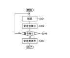
- FIG. 2 is a flowchart for explaining the operation of the wireless network stability display device (wireless network stability display method) in the embodiment of the present invention.
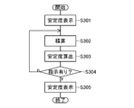
- FIG. 3 is a flowchart for explaining another operation of the stability display device of the wireless network in the embodiment of the present invention.
- FIG. 4 is an explanatory diagram showing a display state on the display unit 103.
- FIG. 1 is a configuration diagram showing a configuration of a wireless network stability display device according to an embodiment of the present invention.
- this device includes a communication control unit 101 that counts the number of transmissions between wireless devices via a wireless network in which wireless communication is performed and the number of non-responses that indicate the number of replies to this transmission.
- this apparatus includes a stability calculation unit 102 that calculates the route stability of a route of a wireless network that has been transmitted based on the number of transmissions and the number of non-replies.
- the apparatus includes a route display control unit 104 that causes the display unit 103 to display a route of the wireless network.
- this apparatus includes a stability display control unit 105 that displays an icon indicating the route stability calculated by the stability calculation unit 102 on the display unit 103 together with a corresponding route.
- the present apparatus includes a display information storage unit 106 that includes the above-described icon information, and a display update unit 107 that updates the display of the icon on the display unit 103 by the stability display control unit 105.
- wireless network stability display device wireless network stability display method
- step S201 the number of non-replies is accumulated.
- the non-reply number is the number of transmissions between wireless devices via a wireless network in which wireless communication is performed, and the number of replies to this transmission.
- This integration of the non-reply number is a counting step and is performed by the communication control unit 101 shown in FIG.
- step S202 the route stability of the route of the wireless network where the transmission was performed is calculated from the accumulated number of transmissions and the number of non-replies.
- This calculation is a calculation step and is performed by the stability calculation unit 102.
- the route stability can be calculated by the following equation (1) (see Non-Patent Document 1).
- Path stability 1- (number of non-replies / number of transmissions) (1)
- step S204 the route of the wireless network is displayed on the display unit 103, and an icon indicating the calculated route stability is added to the corresponding route. At the same time, it is displayed on the display unit 103.
- the display of the route of the wireless network is a route display step and is performed by the route display control unit 104.
- the icon display is a stability display step, and is performed by the stability display control unit 105.
- what is necessary is just to perform the operation
- the wireless network route may be displayed in advance. As shown in the flowchart of FIG. 3, first, in step S ⁇ b> 301, the route of the wireless network is displayed on the display unit 103. Next, in step S302, the non-reply number is accumulated. As described above, the non-reply number is the number of transmissions between wireless devices via a wireless network in which wireless communication is performed, and the number for which no reply is made to this transmission.
- step S303 the route stability of the route of the wireless network where the transmission was performed is calculated from the accumulated number of transmissions and the number of non-replies.
- step S304 an icon indicating the calculated route stability is displayed on the display unit 103 in association with the route.
- the stability display control unit 105 extracts icon information corresponding to the calculated path stability from the icon information stored in the display information storage unit 106, and displays the icon on the display unit 103 based on the icon information. .
- the stability display control unit 105 classifies the route stability into five levels as shown below. First, the state where the path stability is less than 60% is set to “level 0”. Next, the state where the path stability is 60% or more and less than 70% is set to “level 1”. Next, the state where the path stability is 70% or more and less than 80% is set to “level 2”. Next, the state where the path stability is 80% or more and less than 90% is set to “level 3”. Next, a state where the route stability is 90% or more is set as “level 4”. In addition, the stability display control unit 105 selects an icon to be displayed corresponding to the classification.
- a wireless network is constructed from a pressure sensor that is installed in a plant and transmits a pressure value measured by wireless communication, a temperature sensor that is installed in a plant and transmits a temperature value measured by wireless communication, a repeater, and a gateway.
- the gateway is a computer device and constitutes the stability display device of the wireless network in the above-described embodiment.
- the display unit 103 includes an icon 401 corresponding to the pressure sensor, an icon 402 corresponding to the temperature sensor, two icons 411 and 412 corresponding to the relay, and an icon corresponding to the gateway. 413 is displayed.
- the icon 403 corresponds to a temperature sensor.
- the wireless network path between the pressure sensor and one repeater is displayed on the display unit 103 as an arrow icon 421 from the icon 401 to the icon 411.
- the wireless network path between the temperature sensor and the other repeater is displayed on the display unit 103 as an arrow icon 422 from the icon 402 to the icon 412.
- the wireless network path between one repeater and the gateway is displayed on the display unit 103 as an arrow icon 423 from the icon 411 to the icon 413.
- the wireless network path between one repeater and the other repeater is displayed on the display unit 103 as an arrow icon 424 from the icon 411 to the icon 412.
- the wireless network path between the other repeater and the gateway is displayed on the display unit 103 as an arrow icon 425 from the icon 412 to the icon 413.
- an icon 433 indicating the stability of this route is displayed together with an icon 423 of the wireless network route between one repeater and the gateway. Further, an icon 434 indicating the stability of this route is displayed together with an icon 424 of the wireless network route between one repeater and the other repeater. Also, an icon 435 indicating the stability of this route is displayed together with an icon 425 of the wireless network route between the other repeater and the gateway.
- Each icon indicating the above-described stability corresponds to the above-described level of path stability.
- the icon 431 indicates the level 1 state.
- An icon 432, an icon 433, an icon 434, and an icon 435 indicate a level 4 state.
- the icon indicating the stability can be identified by the level of the bar graph displayed on the icon.
- the state of each route is displayed with an icon corresponding to the level of stability depending on the number of transmissions and the number of non-replies, so it is closer to the actual route in the wireless network. Stability can be evaluated. As a result, the wireless network can be monitored with high reliability. In addition, by using icons, the stability of each route can be intuitively evaluated, and can be quickly evaluated.
- the icon indicating the path stability is not limited to a bar graph, and the stability level may be displayed as a pie chart. Further, the icon may be displayed in a shape indicating the stability by the number of bars. Moreover, you may display a stability numerically with this icon.
- the stability of the route via multiple links may be displayed.
- the stability of the gateway path indicated by the pressure sensor indicated by the icon 401, the temperature sensor indicated by the icon 402, the repeater indicated by the icon 412 and the icon 413 in FIG. do it.
- the stability of the icon 401-icon 411 is 0.98
- the stability of the icon 411-icon 412 is 0.91
- the stability of the icon 412-icon 413 is 0.96
- the icon 401-icon 411- The stability of the route of the icon 412 to the icon 413 is 0.86.
- the stability of the route thus obtained may be displayed as described above.
- the link stability needs to be 97% or more (0.97 ⁇ 0.9 1/3 ).
- the stability on the desired route may be displayed.
- the symbol (icon) used for the route display can be variably displayed to indicate the stability of the route, such as changing the color according to the stability and displaying the size differently. May be. Further, the icon may be moved along the route.
Landscapes
- Engineering & Computer Science (AREA)
- Computer Networks & Wireless Communication (AREA)
- Signal Processing (AREA)
- Mobile Radio Communication Systems (AREA)
- Telephone Function (AREA)
Abstract
無線通信が行われている無線ネットワークを介した無線装置間の送信数およびこの送信に対する返信がなされなかった数を示す無返信数を計数する通信制御部(101)と、送信数および無返信数より送信が行われた経路の経路安定度を演算する安定度演算部(102)と、無線ネットワークの経路を表示部(103)に表示させる経路表示制御部(104)と、安定度演算部(102)が演算した経路安定度示すアイコンを対応する経路とともに表示部(103)に表示させる安定度表示制御部(105)とを備える。
Description
本発明は、無線ネットワークの経路情報を表示する無線ネットワークの安定性表示装置および方法に関する。
イーサネット(登録商標)などによる無線ネットワーク環境においては、特に、無線経路の安定性が重要となる。例えば、無線ネットワークでは、電波の干渉や物体の通過により通信の安定性が低下する場合がある。通信が安定しない場合、再送が頻発し、通信の遅延が発生し、また、消費電力の増加が問題となる。このため、最大送信レートにより送信レートを決定して無線ネットワークを確立する技術がある(特許文献1参照)。
L. Doherty et al. , "Channel-Specific Wireless Sensor Network Path Data", Computer Communications and Networks, Proceedings of 16th International Conference on, pp.89-94, 2007.
しかしながら、上述した技術では、最も安定している通信経路が決定されるが、この経路の「安定」が、必要な通信品質が得られている状態であるとは限らない。一方、無線ネットワーク環境において測定される電波強度を、表示により可視化する技術がある(特許文献2参照)。しかしながらこの可視化の技術では、干渉により電波強度が一時的に強くなることまでも考慮した、経路の安定性を評価しているものではない。
本発明は、以上のような問題点を解消するためになされたものであり、無線ネットワークにける経路のより実際に近い安定性が、評価できるようにすることを目的とする。
本発明に係る無線ネットワークの安定性表示装置は、無線通信が行われている無線ネットワークを介した無線装置間の送信数およびこの送信に対する返信がなされなかった数を示す無返信数を計数する通信制御手段と、送信数および無返信数より送信が行われた無線ネットワークの経路の経路安定度を演算する安定度演算手段と、無線ネットワークの経路を表示部に表示させる経路表示制御手段と、安定度演算手段が演算した経路安定度を示すアイコンを対応する経路とともに表示部に表示させる安定度表示制御手段とを少なくとも備える。
上記無線ネットワークの安定性表示装置において、安定度表示制御手段によるアイコンの表示部への表示を更新する表示更新手段を備えるようにしてもよい。
本発明に係る無線ネットワークの安定性表示方法は、無線通信が行われている無線ネットワークを介した無線装置間の送信数およびこの送信に対する返信がなされなかった数を示す無返信数を計数する計数ステップと、送信数および無返信数より送信が行われた無線ネットワークの経路の経路安定度を演算する演算ステップと、無線ネットワークの経路を表示部に表示させる経路表示ステップと、演算した経路安定度を示すアイコンを対応する経路とともに表示部に表示させる安定度表示ステップとを少なくとも備える。
以上説明したように、本発明によれば、送信数および無返信数による経路安定度を示すアイコンを対応する経路とともに表示するようにしたので、無線ネットワークにける経路のより実際に近い安定性が、評価できるようになるという優れた効果が得られる。
以下、本発明の実施の形態について図を参照して説明する。図1は、本発明の実施の形態における無線ネットワークの安定性表示装置の構成を示す構成図である。
この装置は、まず、無線通信が行われている無線ネットワークを介した無線装置間の送信数およびこの送信に対する返信がなされなかった数を示す無返信数を計数する通信制御部101を備える。また、この装置は、送信数および無返信数より送信が行われた無線ネットワークの経路の経路安定度を演算する安定度演算部102を備える。また、この装置は、無線ネットワークの経路を表示部103に表示させる経路表示制御部104を備える。また、この装置は、安定度演算部102が演算した経路安定度示すアイコンを対応する経路とともに表示部103に表示させる安定度表示制御部105を備える。
また、本装置は、上述したアイコンの情報を備える表示情報記憶部106、および、安定度表示制御部105によるアイコンの表示部103への表示を更新する表示更新部107を備える。
次に、本実施の形態における無線ネットワークの安定性表示装置の動作(無線ネットワークの安定性表示方法)について、図2のフローチャートを用いて説明する。
まず、ステップS201で、無返信数を積算する。無返信数は、無線通信が行われている無線ネットワークを介した無線装置間の送信数およびこの送信に対する返信がなされなかった数である。この、無返信数の積算は、計数ステップであり、図1に示した通信制御部101で行う。
次に、ステップS202で、積算された送信数および無返信数より送信が行われた無線ネットワークの経路の経路安定度を演算する。この演算は、演算ステップであり、安定度演算部102で行う。例えば、以下の式(1)により、経路安定度を演算することができる(非特許文献1参照)。
経路安定度=1-(無返信数/送信数)・・・(1)
次に、ステップS203で、経路表示の指示が入力されると、ステップS204で、まず、無線ネットワークの経路を表示部103に表示させ、加えて、演算した経路安定度を示すアイコンを対応する経路とともに表示部103に表示させる。無線ネットワークの経路の表示は、経路表示ステップであり、経路表示制御部104で行う。アイコンの表示は、安定度表示ステップであり、安定度表示制御部105で行う。なお、ステップS201およびステップS202の動作は、設定されている時間毎に周期的に行うようにすればよい。このようにすることで、ネットワーク状態の評価が、より即時的に行える。
また、無線ネットワークの経路は、予め表示しておいてもよい。図3のフローチャートに示すように、まず、ステップS301で、無線ネットワークの経路を表示部103に表示させる。次に、ステップS302で、無返信数を積算する。無返信数は、前述したように、無線通信が行われている無線ネットワークを介した無線装置間の送信数、およびこの送信に対する返信がなされなかった数である。
次に、ステップS303で、積算された送信数および無返信数より送信が行われた無線ネットワークの経路の経路安定度を演算する。次に、ステップS304で、安定度表示の指示が入力されると、演算した経路安定度を示すアイコンを経路に対応させて表示部103に表示させる。
次に、安定度の表示についてより詳細に説明する。安定度表示制御部105は、表示情報記憶部106に記憶されているアイコン情報より、演算した経路安定度に対応するアイコン情報を取り出し、このアイコン情報をもとにアイコンを表示部103に表示させる。
例えば、安定度表示制御部105は、次に示すように、経路安定度を5段階に分類する。まず、経路安定度が60%未満の状態は、「レベル0」とする。次に、経路安定度が60%以上70%未満の状態は、「レベル1」とする。次に、経路安定度が70%以上80%未満の状態は、「レベル2」とする。次に、経路安定度が80%以上90%未満の状態は、「レベル3」とする。次に、経路安定度が90%以上の状態を「レベル4」とする。また、安定度表示制御部105は、上記分類に対応させて表示させるアイコンを選択する。
例えば、プラントに設置されて無線通信により計測した圧力値を送信する圧力センサ、プラントに設置されて無線通信により計測した温度値を送信する温度センサ、中継器、およびゲートウエイとから無線ネットワークが構築されている場合を例にする。ここで、ゲートウエイは、コンピュータ機器であり、上述した本実施の形態における無線ネットワークの安定性表示装置を構成している。
表示部103には、図4に示すように、上記圧力センサに対応するアイコン401、上記温度センサに対応するアイコン402、上記中継器に対応する2つのアイコン411,412、およびゲートウエイに対応するアイコン413が表示される。なお、アイコン403は、温度センサに対応するものである。
また、表示部103には、圧力センサと一方の中継器との間の無線ネットワーク経路が、アイコン401からアイコン411に向かう矢印のアイコン421で表示されている。また、表示部103には、温度センサと他方の中継器との間の無線ネットワーク経路が、アイコン402からアイコン412に向かう矢印のアイコン422で表示されている。また、表示部103には、一方の中継器とゲートウエイとの間の無線ネットワーク経路が、アイコン411からアイコン413に向かう矢印のアイコン423で表示されている。また、表示部103には、一方の中継器と他方の中継器との間の無線ネットワーク経路が、アイコン411からアイコン412に向かう矢印のアイコン424で表示されている。また、表示部103には、他方の中継器とゲートウエイとの間の無線ネットワーク経路が、アイコン412からアイコン413に向かう矢印のアイコン425で表示されている。
上述したように、無線ネットワークの経路が表示部103により可視化されている中で、まず、圧力センサと一方の中継器との間の無線ネットワーク経路のアイコン421とともに、この経路の安定度を示すアイコン431が表示される。また、温度センサと他方の中継器との間の無線ネットワーク経路のアイコン422とともに、この経路の安定度を示すアイコン432が表示される。
また、一方の中継器とゲートウエイとの間の無線ネットワーク経路のアイコン423とともに、この経路の安定度を示すアイコン433が表示される。また、一方の中継器と他方の中継器との間の無線ネットワーク経路のアイコン424とともに、この経路の安定度を示すアイコン434が表示される。また、他方の中継器とゲートウエイとの間の無線ネットワーク経路のアイコン425とともに、この経路の安定度を示すアイコン435が表示される。
上述した安定度を示す各アイコンは、前述した経路安定度のレベルに対応したものとなっている。上記例では、アイコン431が、レベル1の状態を示している。また、アイコン432,アイコン433,アイコン434,アイコン435は、レベル4の状態を示している。この安定度を示すアイコンは、アイコンに表示される棒グラフの状態により、上述したレベルが識別可能となっている。
上述したように、本実施の形態によれば、各経路の状態が、送信数および無返信数よる安定度のレベルに応じたアイコンで表示されるので、無線ネットワークにける経路のより実際に近い安定性が、評価できるようになる。この結果、無線ネットワークの監視が、信頼性の高い状態で行えるようになる。また、アイコンを用いることで、各経路の安定性が直感的に評価できるようになり、また、素早く評価できるようになる。
なお、本発明は以上に説明した実施の形態に限定されるものではなく、本発明の技術的思想内で、当分野において通常の知識を有する者により、多くの変形および組み合わせが実施可能であることは明白である。例えば、経路安定度を示すアイコンは、棒グラフを用いたものに限らず、安定度のレベルを円グラフで表示するようにしてもよい。また、アイコンは、安定度をバーの本数で示す形状で表示してもよい。また、このアイコンとともに、安定度を数値で表示してもよい。
また、複数のリンクを経由した経路の安定度を表示してもよい。例えば、図4の、アイコン401で示す圧力センサ-アイコン402で示す温度センサ-アイコン412で示す中継器-アイコン413で示すゲートウエイの経路の安定度は、各ノード間のリンクの安定度の積とすればよい。
例えば、アイコン401-アイコン411の安定度が0.98,アイコン411-アイコン412の安定度が0.91,アイコン412-アイコン413の安定度が0.96であれば、アイコン401-アイコン411-アイコン412-アイコン413の経路の安定度は、0.86となる。このようにして求めた経路の安定度を、前述同様に表示すればよい。
また、例えば、前述したように経路安定度が90%以上の状態である「レベル4」のアイコンが、上記経路に表示されるためには、上記経路におけるリンクの数は3であるので、各リンクにおける安定度は97%以上(0.97≒0.91/3)となっている必要がある。
また、前ネットワークではなく、所望とする経路上の安定度のみを表示するようにしてもよい。また、安定度に対応して色を変えて表示する,大きさを変えて表示するなど、経路表示に用いている記号(アイコン)を可変表示することで、当該経路の安定度を示すようにしてもよい。また、経路にそってアイコンが移動していくようにしてもよい。
101…通信制御部、102…安定度演算部、103…表示部、104…経路表示制御部、106…表示情報記憶部、107…表示更新部。
Claims (3)
- 無線通信が行われている無線ネットワークを介した無線装置間の送信数およびこの送信に対する返信がなされなかった数を示す無返信数を計数する通信制御手段と、
前記送信数および前記無返信数より送信が行われた前記無線ネットワークの経路の経路安定度を算出する安定度演算手段と、
前記無線ネットワークの経路を表示部に表示させる経路表示制御手段と、
前記安定度演算手段が算出した経路安定度を示すアイコンを対応する経路とともに前記表示部に表示させる安定度表示制御手段と
を備えることを特徴とする無線ネットワークの安定性表示装置。 - 請求項1記載の無線ネットワークの安定性表示装置において、
前記安定度表示制御手段による前記アイコンの前記表示部への表示を更新する表示更新手段をさらに備えることを特徴とする無線ネットワークの安定性表示装置。 - 無線通信が行われている無線ネットワークを介した無線装置間の送信数およびこの送信に対する返信がなされなかった数を示す無返信数を計数する計数ステップと、
前記送信数および前記無返信数より送信が行われた前記無線ネットワークの経路の経路安定度を算出する算出ステップと、
前記無線ネットワークの経路を表示部に表示させる経路表示ステップと、
算出した経路安定度を示すアイコンを対応する経路とともに前記表示部に表示させる安定度表示ステップと
を備えることを特徴とする無線ネットワークの安定性表示方法。
Applications Claiming Priority (2)
| Application Number | Priority Date | Filing Date | Title |
|---|---|---|---|
| JP2010-290898 | 2010-12-27 | ||
| JP2010290898A JP2012138830A (ja) | 2010-12-27 | 2010-12-27 | 無線ネットワークの安定性表示装置および方法 |
Publications (1)
| Publication Number | Publication Date |
|---|---|
| WO2012090604A1 true WO2012090604A1 (ja) | 2012-07-05 |
Family
ID=46382725
Family Applications (1)
| Application Number | Title | Priority Date | Filing Date |
|---|---|---|---|
| PCT/JP2011/076177 Ceased WO2012090604A1 (ja) | 2010-12-27 | 2011-11-14 | 無線ネットワークの安定性表示装置および方法 |
Country Status (3)
| Country | Link |
|---|---|
| JP (1) | JP2012138830A (ja) |
| TW (1) | TW201233214A (ja) |
| WO (1) | WO2012090604A1 (ja) |
Families Citing this family (1)
| Publication number | Priority date | Publication date | Assignee | Title |
|---|---|---|---|---|
| KR101463628B1 (ko) | 2008-12-17 | 2014-11-19 | 제네럴 일렉트릭 컴퍼니 | 가동 터빈 베인용 부싱 및 클럭 스프링 조립체 |
Citations (3)
| Publication number | Priority date | Publication date | Assignee | Title |
|---|---|---|---|---|
| JP2002271399A (ja) * | 2001-03-09 | 2002-09-20 | Nec Corp | 電話システム及び電話接続監視方法 |
| JP2003244146A (ja) * | 2002-02-19 | 2003-08-29 | Hitachi Ltd | ネットワーク監視装置におけるトラフィックトレンドリプレイ表示装置 |
| JP2010146306A (ja) * | 2008-12-19 | 2010-07-01 | Hitachi Information Systems Ltd | 構成監視システム及び構成監視方法 |
-
2010
- 2010-12-27 JP JP2010290898A patent/JP2012138830A/ja active Pending
-
2011
- 2011-10-31 TW TW100139553A patent/TW201233214A/zh unknown
- 2011-11-14 WO PCT/JP2011/076177 patent/WO2012090604A1/ja not_active Ceased
Patent Citations (3)
| Publication number | Priority date | Publication date | Assignee | Title |
|---|---|---|---|---|
| JP2002271399A (ja) * | 2001-03-09 | 2002-09-20 | Nec Corp | 電話システム及び電話接続監視方法 |
| JP2003244146A (ja) * | 2002-02-19 | 2003-08-29 | Hitachi Ltd | ネットワーク監視装置におけるトラフィックトレンドリプレイ表示装置 |
| JP2010146306A (ja) * | 2008-12-19 | 2010-07-01 | Hitachi Information Systems Ltd | 構成監視システム及び構成監視方法 |
Also Published As
| Publication number | Publication date |
|---|---|
| TW201233214A (en) | 2012-08-01 |
| JP2012138830A (ja) | 2012-07-19 |
Similar Documents
| Publication | Publication Date | Title |
|---|---|---|
| US9860819B2 (en) | Wireless device link metric for effective comparison of multi-hop routes in wireless mesh networks | |
| JP5908293B2 (ja) | メッシュネットワーク内で無効なノードを識別するシステム、方法、および装置 | |
| US8667084B2 (en) | Managing fate-sharing in shared-media communication networks | |
| US20110228696A1 (en) | Dynamic directed acyclic graph (dag) topology reporting | |
| US10805194B2 (en) | Proactive path quality reporting in packet transmission | |
| US9013983B2 (en) | Proactive source-based reverse path validation in computer networks | |
| US20130107909A1 (en) | Multi-path radio transmission input/output devices, network, systems and methods with link suitability determination | |
| EP3310009A1 (en) | A framework for traffic engineering in software defined networking | |
| CN107509235A (zh) | 具有按需分优先级路由协议的多径无线电通信网络 | |
| Beytur et al. | Towards AoI-aware smart IoT systems | |
| WO2007082011A3 (en) | Visual mapping of field device message routes in a wireless mesh network | |
| JP5884812B2 (ja) | 通信装置及び無線通信システム | |
| US20200145897A1 (en) | METHOD AND DEVICE FOR ROUTING DATA IN 6TiSCH NETWORKS | |
| Birand et al. | Dynamic graph properties of mobile networks under levy walk mobility | |
| JP5058020B2 (ja) | 通信システム | |
| WO2012090604A1 (ja) | 無線ネットワークの安定性表示装置および方法 | |
| US20210184892A1 (en) | Method of controlling communication system, communication system, and relay device | |
| CN111294835A (zh) | 动态路径损耗减轻 | |
| JP2015099953A (ja) | 通信経路表示装置および方法 | |
| US10931551B2 (en) | Condition monitoring of wireless networks in industrial plants | |
| JP5584017B2 (ja) | シーケンス試験装置及びシーケンス試験方法 | |
| US20230198890A1 (en) | Enhancing route selection of optimized link state routing using a link probing tool | |
| WO2008134764A4 (en) | Topographical display generator for ad hoc network | |
| JP2015173400A (ja) | ネットワーク監視装置およびネットワーク監視方法 | |
| JP7402967B2 (ja) | 空調システム管理装置および空調システム管理方法 |
Legal Events
| Date | Code | Title | Description |
|---|---|---|---|
| 121 | Ep: the epo has been informed by wipo that ep was designated in this application |
Ref document number: 11852331 Country of ref document: EP Kind code of ref document: A1 |
|
| NENP | Non-entry into the national phase |
Ref country code: DE |
|
| 122 | Ep: pct application non-entry in european phase |
Ref document number: 11852331 Country of ref document: EP Kind code of ref document: A1 |