WO2012090396A1 - 帯状生地の染料液塗布装置 - Google Patents
帯状生地の染料液塗布装置 Download PDFInfo
- Publication number
- WO2012090396A1 WO2012090396A1 PCT/JP2011/006791 JP2011006791W WO2012090396A1 WO 2012090396 A1 WO2012090396 A1 WO 2012090396A1 JP 2011006791 W JP2011006791 W JP 2011006791W WO 2012090396 A1 WO2012090396 A1 WO 2012090396A1
- Authority
- WO
- WIPO (PCT)
- Prior art keywords
- belt
- application
- webbing
- dye solution
- cloth
- Prior art date
- Legal status (The legal status is an assumption and is not a legal conclusion. Google has not performed a legal analysis and makes no representation as to the accuracy of the status listed.)
- Ceased
Links
Images


Classifications
-
- B—PERFORMING OPERATIONS; TRANSPORTING
- B05—SPRAYING OR ATOMISING IN GENERAL; APPLYING FLUENT MATERIALS TO SURFACES, IN GENERAL
- B05C—APPARATUS FOR APPLYING FLUENT MATERIALS TO SURFACES, IN GENERAL
- B05C1/00—Apparatus in which liquid or other fluent material is applied to the surface of the work by contact with a member carrying the liquid or other fluent material, e.g. a porous member loaded with a liquid to be applied as a coating
- B05C1/04—Apparatus in which liquid or other fluent material is applied to the surface of the work by contact with a member carrying the liquid or other fluent material, e.g. a porous member loaded with a liquid to be applied as a coating for applying liquid or other fluent material to work of indefinite length
- B05C1/08—Apparatus in which liquid or other fluent material is applied to the surface of the work by contact with a member carrying the liquid or other fluent material, e.g. a porous member loaded with a liquid to be applied as a coating for applying liquid or other fluent material to work of indefinite length using a roller or other rotating member which contacts the work along a generating line
-
- B—PERFORMING OPERATIONS; TRANSPORTING
- B05—SPRAYING OR ATOMISING IN GENERAL; APPLYING FLUENT MATERIALS TO SURFACES, IN GENERAL
- B05C—APPARATUS FOR APPLYING FLUENT MATERIALS TO SURFACES, IN GENERAL
- B05C1/00—Apparatus in which liquid or other fluent material is applied to the surface of the work by contact with a member carrying the liquid or other fluent material, e.g. a porous member loaded with a liquid to be applied as a coating
- B05C1/006—Apparatus in which liquid or other fluent material is applied to the surface of the work by contact with a member carrying the liquid or other fluent material, e.g. a porous member loaded with a liquid to be applied as a coating for applying liquid or other fluent material to the edges of essentially flat articles
-
- B—PERFORMING OPERATIONS; TRANSPORTING
- B05—SPRAYING OR ATOMISING IN GENERAL; APPLYING FLUENT MATERIALS TO SURFACES, IN GENERAL
- B05C—APPARATUS FOR APPLYING FLUENT MATERIALS TO SURFACES, IN GENERAL
- B05C1/00—Apparatus in which liquid or other fluent material is applied to the surface of the work by contact with a member carrying the liquid or other fluent material, e.g. a porous member loaded with a liquid to be applied as a coating
- B05C1/04—Apparatus in which liquid or other fluent material is applied to the surface of the work by contact with a member carrying the liquid or other fluent material, e.g. a porous member loaded with a liquid to be applied as a coating for applying liquid or other fluent material to work of indefinite length
- B05C1/08—Apparatus in which liquid or other fluent material is applied to the surface of the work by contact with a member carrying the liquid or other fluent material, e.g. a porous member loaded with a liquid to be applied as a coating for applying liquid or other fluent material to work of indefinite length using a roller or other rotating member which contacts the work along a generating line
- B05C1/0813—Apparatus in which liquid or other fluent material is applied to the surface of the work by contact with a member carrying the liquid or other fluent material, e.g. a porous member loaded with a liquid to be applied as a coating for applying liquid or other fluent material to work of indefinite length using a roller or other rotating member which contacts the work along a generating line characterised by means for supplying liquid or other fluent material to the roller
-
- B—PERFORMING OPERATIONS; TRANSPORTING
- B05—SPRAYING OR ATOMISING IN GENERAL; APPLYING FLUENT MATERIALS TO SURFACES, IN GENERAL
- B05C—APPARATUS FOR APPLYING FLUENT MATERIALS TO SURFACES, IN GENERAL
- B05C1/00—Apparatus in which liquid or other fluent material is applied to the surface of the work by contact with a member carrying the liquid or other fluent material, e.g. a porous member loaded with a liquid to be applied as a coating
- B05C1/04—Apparatus in which liquid or other fluent material is applied to the surface of the work by contact with a member carrying the liquid or other fluent material, e.g. a porous member loaded with a liquid to be applied as a coating for applying liquid or other fluent material to work of indefinite length
- B05C1/08—Apparatus in which liquid or other fluent material is applied to the surface of the work by contact with a member carrying the liquid or other fluent material, e.g. a porous member loaded with a liquid to be applied as a coating for applying liquid or other fluent material to work of indefinite length using a roller or other rotating member which contacts the work along a generating line
- B05C1/0826—Apparatus in which liquid or other fluent material is applied to the surface of the work by contact with a member carrying the liquid or other fluent material, e.g. a porous member loaded with a liquid to be applied as a coating for applying liquid or other fluent material to work of indefinite length using a roller or other rotating member which contacts the work along a generating line the work being a web or sheets
-
- B—PERFORMING OPERATIONS; TRANSPORTING
- B05—SPRAYING OR ATOMISING IN GENERAL; APPLYING FLUENT MATERIALS TO SURFACES, IN GENERAL
- B05C—APPARATUS FOR APPLYING FLUENT MATERIALS TO SURFACES, IN GENERAL
- B05C1/00—Apparatus in which liquid or other fluent material is applied to the surface of the work by contact with a member carrying the liquid or other fluent material, e.g. a porous member loaded with a liquid to be applied as a coating
- B05C1/04—Apparatus in which liquid or other fluent material is applied to the surface of the work by contact with a member carrying the liquid or other fluent material, e.g. a porous member loaded with a liquid to be applied as a coating for applying liquid or other fluent material to work of indefinite length
- B05C1/16—Apparatus in which liquid or other fluent material is applied to the surface of the work by contact with a member carrying the liquid or other fluent material, e.g. a porous member loaded with a liquid to be applied as a coating for applying liquid or other fluent material to work of indefinite length only at particular parts of the work
- B05C1/165—Apparatus in which liquid or other fluent material is applied to the surface of the work by contact with a member carrying the liquid or other fluent material, e.g. a porous member loaded with a liquid to be applied as a coating for applying liquid or other fluent material to work of indefinite length only at particular parts of the work using a roller or other rotating member which contacts the work along a generating line
-
- B—PERFORMING OPERATIONS; TRANSPORTING
- B05—SPRAYING OR ATOMISING IN GENERAL; APPLYING FLUENT MATERIALS TO SURFACES, IN GENERAL
- B05C—APPARATUS FOR APPLYING FLUENT MATERIALS TO SURFACES, IN GENERAL
- B05C11/00—Component parts, details or accessories not specifically provided for in groups B05C1/00 - B05C9/00
- B05C11/10—Storage, supply or control of liquid or other fluent material; Recovery of excess liquid or other fluent material
- B05C11/1039—Recovery of excess liquid or other fluent material; Controlling means therefor
-
- D—TEXTILES; PAPER
- D06—TREATMENT OF TEXTILES OR THE LIKE; LAUNDERING; FLEXIBLE MATERIALS NOT OTHERWISE PROVIDED FOR
- D06B—TREATING TEXTILE MATERIALS USING LIQUIDS, GASES OR VAPOURS
- D06B1/00—Applying liquids, gases or vapours onto textile materials to effect treatment, e.g. washing, dyeing, bleaching, sizing or impregnating
- D06B1/10—Applying liquids, gases or vapours onto textile materials to effect treatment, e.g. washing, dyeing, bleaching, sizing or impregnating by contact with a member carrying the treating material
- D06B1/14—Applying liquids, gases or vapours onto textile materials to effect treatment, e.g. washing, dyeing, bleaching, sizing or impregnating by contact with a member carrying the treating material with a roller
- D06B1/148—Applying liquids, gases or vapours onto textile materials to effect treatment, e.g. washing, dyeing, bleaching, sizing or impregnating by contact with a member carrying the treating material with a roller the treating material being supplied to the roller by spraying or pouring
-
- D—TEXTILES; PAPER
- D06—TREATMENT OF TEXTILES OR THE LIKE; LAUNDERING; FLEXIBLE MATERIALS NOT OTHERWISE PROVIDED FOR
- D06B—TREATING TEXTILE MATERIALS USING LIQUIDS, GASES OR VAPOURS
- D06B11/00—Treatment of selected parts of textile materials, e.g. partial dyeing
- D06B11/0056—Treatment of selected parts of textile materials, e.g. partial dyeing of fabrics
-
- D—TEXTILES; PAPER
- D06—TREATMENT OF TEXTILES OR THE LIKE; LAUNDERING; FLEXIBLE MATERIALS NOT OTHERWISE PROVIDED FOR
- D06P—DYEING OR PRINTING TEXTILES; DYEING LEATHER, FURS OR SOLID MACROMOLECULAR SUBSTANCES IN ANY FORM
- D06P7/00—Dyeing or printing processes combined with mechanical treatment
Definitions
- the present invention relates to a technical field of a dye solution coating apparatus for a belt-like fabric, which is used in a seat belt device mounted on a vehicle such as an automobile and applies a dye solution to an elongated flexible belt-like fabric such as webbing that restrains an occupant. Belongs.
- a seat belt device that has been installed in a vehicle such as an automobile restrains the occupant with the seat belt in an emergency in which a large deceleration occurs in the vehicle such as a vehicle collision.
- a seat belt is composed of an elongated webbing which is a flexible belt-like fabric.
- both sides of a webbing fabric used for a seat belt may be formed in various colors or various patterns by applying various color dye solutions.
- various dye solution coating apparatuses for belt-shaped fabrics have been proposed.
- FIG. 4 is a diagram showing the inkjet dyeing apparatus described in Patent Document 1.
- 1 is an inkjet dyeing apparatus
- 2 is a carry-in section
- 2a is a carry-in dancer roller
- 2b is a carry-in tension roller
- 3 is a first printing section
- 3a is a first inkjet head
- 3b is a first ink.
- Tank 4 is the second printing unit
- 4a is the second inkjet head
- 4b is the second ink tank
- 5 is the first surface drying unit
- 6 is the first reversing unit
- 7 is the second surface drying.
- , 8 is the second reversing unit
- 9 is the first back surface drying unit
- 10 is the second back surface drying unit
- 11 is the unloading unit
- 11a is the unloading side dancer roller
- 11b is the unloading side tension roller
- 12 to 30 Is a conveyance roller
- 31 is a control unit
- 32 is a webbing that is a belt fabric for a seat belt.
- the controller 31 rotates and drives the carry-in dancer roller 2a when the ink liquid, which is a dye liquid, is applied to both the front and back surfaces of the webbing 32. Then, the webbing 32 that is the material of the seat belt is carried into the inkjet dyeing apparatus 1 from the carry-in unit 2. Then, the webbing 32 passes through the carry-in side dancer roller 2a and the carry-in side tension roller 2b and enters the inkjet dyeing apparatus 1.
- the webbing 32 is transported by the transport rollers 12 to 14 and the surface of the webbing 32 reaches a position facing the first inkjet 3a of the first printing unit 3 (the surface is upward). Then, the control unit 31 operates the first inkjet 3 a, and the first inkjet 3 a ejects the ink liquid in the first ink tank 3 b and applies it to the surface of the webbing 32. Further, the webbing 32 is conveyed by the conveyance roller 15 and reaches a position facing the second inkjet 4 a of the second printing unit 4. Then, the control unit 31 activates the second inkjet 4 a, and the second inkjet 4 a ejects the ink liquid in the second ink tank 4 b and applies it to the surface of the webbing 32.
- the webbing 32 is transported by the transport rollers 16 to 20 and reaches the first surface drying unit 5 and the first reversing unit 6. At this time, when the webbing 32 reaches the conveying rollers 16 to 20, the back surface thereof is directed upward.
- the webbing is rotated about 90 degrees by the first reversing unit 6 while the surface of the webbing 32 to which the ink liquid is applied is dried by the first surface drying unit 5.
- the webbing 32 is conveyed by the conveying roller 21 and reaches the second surface drying unit 7 and the second reversing unit 8. Then, the webbing 32 is further rotated about 90 degrees by the second reversing unit 6 while the surface of the webbing 32 coated with the ink liquid is dried by the second surface drying unit 7.
- the webbing 32 is inverted 180 degrees, and when the webbing 32 reaches the conveying roller 22, the surface thereof is directed upward.
- the webbing 32 is transported by the transport rollers 22 and 23 and reaches the transport roller 13 again.
- the webbing 32 transported from the carry-in unit 2 and the webbing 32 transported by the transport rollers 22 and 23 and coated with ink liquid on the surface thereof are in the axial direction of the transport roller 13. Misaligned and transported in parallel.
- these two webbings 32 are transported in parallel from the transport roller 13 to the transport roller 18.
- the two webbings 32 transported in parallel reach the position facing the first inkjet 3 a of the first printing unit 3.
- the front surface of the webbing 32 conveyed from the carry-in unit 2 is directed upward, and the back surface of the webbing 32 coated with ink liquid is directed upward.
- the operating first ink jet 3 a applies the ink liquid to the surface of one webbing 32 and the back surface of the other webbing 32 in the same manner as described above. Further, the two webbings 32 are conveyed in parallel to a position facing the second inkjet 4 a of the second printing unit 4. Then, the second inkjet 4 a of the second printing unit 4 applies the ink liquid to the front surface of one webbing 32 and the back surface of the other webbing 32 in the same manner.
- the two webbings 32 conveyed in parallel reach the conveyance roller 18 the one webbing 32 coated with the ink only on the surface is conveyed toward the first surface drying unit 5 in the same manner as described above. Thereafter, the coating treatment is performed in the same manner as described above.
- the other webbing 32 having the ink liquid applied to both the front and back surfaces is conveyed toward the conveying roller 24.
- the webbing 32 reaches the transport roller 24, the webbing 32 is transported by the transport rollers 24 and 25 and reaches the first back surface drying unit 9.
- the back surface of the webbing 32 to which the ink liquid is applied is dried by the first back surface drying unit 9.
- the webbing 32 is transported by the transport rollers 26 and 27 and reaches the second back surface drying unit 10.
- the back surface of the webbing 32 to which the ink liquid is applied is dried by the second back surface drying unit 10.
- the webbing 32 is transported by the transport rollers 28 to 30 and enters the unloading unit 11. Then, the webbing 32 is carried out of the inkjet dyeing apparatus 1 through the carry-out side tension roller 11b and the carry-out side dancer roller 11a.
- the ink liquid is continuously applied to both the front and back surfaces of the elongated webbing 32 by the inkjet dyeing apparatus 1.
- the dye solution is applied not only on both the front and back sides of the belt-like fabric, but also on both side edges of the elongated belt-like fabric. Some belt-like fabrics are required.
- the ink liquid can be effectively applied to both the front and back surfaces of the webbing 32, but it is difficult to apply the ink liquid to both side edges of the webbing 32.
- the present invention has been made in view of such circumstances, and an object thereof is to provide an effect of applying a dye solution on at least one of the front and back surfaces of the elongated strip-shaped fabric and at least one side edge of both side edges. It is an object to provide a dye solution coating apparatus for a belt-shaped fabric that can be applied in an automatic manner.
- a belt-like cloth dye solution coating apparatus is provided with a dye on at least one surface of a carrying-in section for carrying in a belt-like cloth and both sides of the belt-like cloth carried in from the carrying-in part.
- the position of the side edge applying part can be adjusted so as to contact and separate from the side edges of the belt-like cloth carried out from the carry-out part.
- a pair of application rollers rotatable so as to apply the dye solution to each side edge of the belt-like fabric.
- the dye solution coating apparatus for a belt-shaped dough according to the present invention is characterized in that the pair of coating rollers each have a sheet-shaped coating member impregnated with the dye solution.
- the dye solution coating apparatus for a belt-like cloth according to the present invention is characterized in that the pair of application rollers rotate together with the movement of the belt-like cloth. Furthermore, in the dye solution coating apparatus for a belt-like cloth according to the present invention, the pair of coating rollers has a truncated cone-shaped portion or a cone-shaped portion at their upper ends, and the truncated cone-shaped portion. Alternatively, the dye solution is dropped or flowed down on the conical portion.
- the belt-like cloth dye solution coating apparatus is characterized by having a tension member that applies tension to the belt-like cloth carried out from the carry-out portion in the longitudinal direction of the belt-like cloth. Furthermore, the belt-like cloth dye solution coating apparatus according to the present invention is characterized in that the belt-like cloth is a webbing for a seat belt.
- the surface coating section and the side edge coating section are disposed. Therefore, it is possible to apply the dye solution to the at least one side edge of the both sides of the belt-like cloth which is unloaded from the carry-out portion of the surface application portion and applied to at least one of the front and back surfaces by the side edge application portion. It becomes possible.
- a pair of application rollers for applying the dye solution to at least one side edge of both side edges of the belt-like cloth is disposed in the side edge application part.
- the pair of application rollers are arranged so that the position can be adjusted, when it is not necessary to apply the dye solution to at least one of the side edges of the belt-like cloth, the side where the dye solution does not need to be applied is provided.
- the application roller corresponding to the edge can be positioned so as not to contact the side edge. Thereby, it becomes possible to respond flexibly to the application of the dye solution to the side edge of the belt-like fabric.
- each of the pair of application rollers has a sheet-like application member impregnated with the dye solution.
- dough can be formed cheaply and easily.
- each application roller is rotated together with the movement of the belt-like fabric. This eliminates the need for a drive source such as a motor or an electromagnetic solenoid for driving each application roller. As a result, the structure of the side edge application portion can be further simplified and the cost can be reduced.
- each application roller is a truncated truncated cone shape portion or a cone shape portion.
- the dye liquid dropped or flowing down on the truncated cone-shaped portion or the cone-shaped portion can be caused to flow down while spreading over the entire circumference of the outer peripheral surface of each coating roller by rotating each coating roller. Thereby, it becomes possible to effectively and simply impregnate the entire coating member with the dye solution.
- the belt-like cloth carried out from the carry-out part of the surface application part is a tension member, and tension is applied in the longitudinal direction of the belt-like cloth.
- the belt-like fabric dye solution applying apparatus by applying the dye solution to at least one side of both the front and back surfaces of the webbing for seat belts and at least one side edge of the both sides of the belt-like fabric by the belt-like fabric dye solution applying apparatus according to the present invention, Various colors of seat belts and various patterns of seat belts can be formed, and it is possible to flexibly respond to various needs of users for seat belts.
- FIG. 1 shows typically an example of embodiment of the dye liquid coating device of the strip
- FIG. 1 shows typically an example of embodiment of the dye liquid coating device of the strip
- FIG. 1 is a diagram schematically illustrating an example of an embodiment of a dye solution coating apparatus for a belt-shaped dough according to the present invention.
- the same components as those in the conventional ink jet dyeing apparatus 1 shown in FIG. 4 are denoted by the same reference numerals, and detailed description thereof is omitted.
- the belt-like fabric dye solution coating apparatus of this example is an ink-jet dyeing device 1 that applies an ink solution to a webbing 32 for a seat belt, which is a flexible belt-like fabric of a seat belt, as described above. It is.
- the inkjet dyeing apparatus 1 of this example includes a surface application part (or surface printing part) 33 that applies ink liquid to both front and back surfaces of the webbing 32, and a side edge application part that applies ink liquid to both side edges of the webbing 32 (or , Side edge printing section) 34.
- the surface coating unit 33 is the same as the ink jet dyeing apparatus shown in FIG. 5 of Patent Document 1, that is, the same as the ink jet dyeing apparatus shown in FIG. 4 described above. Therefore, the configuration and operational effects of the surface coating unit 33 can be easily understood by referring to the description in Patent Document 1 and the description of the inkjet dyeing apparatus shown in FIG. 4 described above. Detailed description is omitted.
- symbol shown in above-mentioned FIG. 4 is attached
- FIG. 2 is an enlarged view of the side edge application portion shown in FIG. 1
- FIG. 3 is a partially enlarged view seen from the III direction in FIG.
- the side edge coating unit 34 in the inkjet dyeing apparatus 1 of this example is disposed in the conveyance path of the webbing 32 that has been carried out from the carry-out unit 11 of the surface coating unit 33.
- the side edge application unit 34 includes a pair of application rollers 35, 36, two ink liquid storage containers 37, 38, two on-off valves 39, 40, and two flexible pipes (tubes) 41, 42, 2.
- One nozzle 43, 44, one columnar or cylindrical guide 45, and a collection container 46 are provided.
- Each coating roller 35, 36 includes a roller body 35a, 36a, each coating member 35b, 36b fixed to each roller body 35a, 36a, supported portions 35c, 36c, and fixing screws 35d, 36d.
- Each roller main body 35a, 36a is rotatably supported by a rotation shaft (not shown) projecting from each supported portion 35c, 36c.
- Each roller main body 35a, 36a is composed of cylindrical portions 35e, 36e and frusto-conical frustoconical portions (or conical portions) 35f, 36f formed at the upper ends thereof.
- Each of the coating members 35b and 36b is formed of a relatively soft ink liquid impregnated member in the form of a thin sheet such as felt or foam material having an ink liquid impregnation property for impregnating the ink liquid.
- These application members 35b and 36b are wound and fixed on the outer peripheral surfaces of the cylindrical portions 35e and 36e of the roller bodies 35a and 36a, respectively.
- the supported portions 35c and 36c have circular through holes 35g and 36g, respectively, and these through holes 35g and 36g are slidably fitted to the guide 45.
- the guide 45 extends in a direction perpendicular to or substantially perpendicular to the conveyance direction of the webbing 32. Accordingly, each of the application rollers 35 and 36 is guided by the guide 45 and can move in a direction perpendicular to or substantially perpendicular to the conveyance direction of the webbing 32, and can approach and separate from each other.
- the application rollers 35 and 36 can be fixed to arbitrary predetermined positions of the guide 45 with the fixing screws 35d and 36d, respectively. In this case, as shown in FIG. 3, the application rollers 35 and 36 are positioned so that the application members 35 b and 36 b abut against the both side edges 32 a and 32 b of the webbing 32 carried out from the carry-out part 11 relatively weakly. Fixed. When the webbing 32 moves with both side edges 32a and 32b of the webbing 32 being in contact with the coating members 35b and 36b, the coating rollers 35 and 36 are rotated together with the movement of the webbing 32. Has been.
- the ink liquid storage containers 37 and 38 store the ink liquid 47 applied to the webbing 32, respectively. In that case, ink liquids 47 of the same color or different colors are stored in the ink liquid storage containers 37 and 38 in accordance with the desired color of the ink liquid.
- Each on-off valve 39, 40 can be manually opened and closed, and each pipe (tube) 41, 42 has an ink liquid storage container 37, 38 when the on-off valve 39, 40 is opened.
- the ink liquid 47 is supplied to the nozzles 43 and 44. In that case, the valve opening amounts of the on-off valves 39 and 40 can be adjusted, and a desired amount of ink liquid 47 can be supplied to the nozzles 43 and 44.
- the nozzles 43 and 44 respectively drop or flow the supplied ink liquid 47 onto the truncated truncated cone shape portions (or cone shape portions) 35f and 36f.
- the collection container 46 collects excess ink liquid that is not impregnated in each of the coating members 35b and 36b out of the ink liquid dropped or flowed down on the truncated cone-shaped portions (or conical shape portions) 35f and 36f. And store.
- the inkjet dyeing apparatus 1 includes a tension roller 48 and transport rollers 49 and 50 disposed on the downstream side of the webbing 32 in the transport direction from the side edge coating unit 34.
- the tension roller 48 applies tension to the webbing 32 carried out from the carry-out unit 11 to tension the webbing 32 in the longitudinal direction.
- Each of the transport rollers 49 and 50 transports the webbing 32 that has passed through the side edge application unit 34 to a transport cart 51 that is prepared at a predetermined position in the vicinity of the inkjet dyeing apparatus 1.
- the transported webbing 32 is stored in the transport cart 51. Further, the transport carriage 51 transports the stored webbing 32 to the next process for the webbing 32.
- the application members 35b and 36b of the application rollers 35 and 36 are relatively weakly in contact with both side edges 32a and 32b of the webbing 32 carried out from the carry-out portion 11. Positioned and fixed as possible. Also, the on-off valves 39 and 40 are opened, and a predetermined amount of the ink liquid 47 in the ink liquid storage containers 37 and 38 is supplied from the nozzles 43 and 44 to the frusto-conical frustoconical portions of the application rollers 35 and 36, respectively. Dripping or flowing down on 35f, 36f.
- the ink liquid 47 dropped or flowing on the frustoconical shape portions 35f, 36f flows down along the inclined surfaces of the frustoconical shape portions 35f, 36f and the outer peripheral surfaces of the roller bodies 35a, 36a, respectively.
- the coating members 35b and 36b are impregnated. Excess ink liquid 47 other than the ink liquid 47 impregnated in each of the application members 35b and 36b falls into the collection container 46, and is stored and collected.
- the webbing 32 is unloaded from the unloading unit 11 after the ink liquid 47 is applied to both the front and back surfaces as in the conventional case.
- the unloaded webbing 32 passes through the side edge application unit 34 and is conveyed to the tension roller 42, and the tension roller 42 applies tension in the longitudinal direction of the webbing 32 and is tensioned.
- the application rollers 35 and 36 rotate as the webbing 32 moves. Then, by the rotation of the application rollers 35 and 36, the ink liquid 47 dropped or flown onto the frustoconical frustoconical portions 35f and 36f also flows in the circumferential direction of the roller bodies 35a and 36a.
- both side edges 32a and 32b of the webbing 32 come into weak contact with the application members 35b and 36b. Then, the ink liquid 47 impregnated in each application member 35b, 36b is applied to both side edges 32a, 32b of the webbing 32. At this time, since the webbing 32 carried out from the carry-out part 11 is tensioned in the longitudinal direction by the tension roller 42, the webbing 32 has a width even if its both side edges 32a and 32b abut against the application members 35b and 36b. It will not bend in the direction. Accordingly, the ink liquid is stably and sufficiently applied to both side edges 32a and 32b of the webbing 32 by the application members 35b and 36b.
- the webbing 32 unloaded from the unloading unit 11 and coated with the ink liquid 47 on both front and back surfaces passes through the side edge coating unit 34 and further coated with the ink liquid 47 on both side edges 32a and 32b. 50 is transported and accommodated by a transport cart 51.
- a transport cart 51 When a predetermined amount of the webbing 32 is stored in the transport carriage 51 after the ink liquid application process is completed, the webbing 32 is transported by the transport carriage 51 to a place where the next process is performed.
- the two application rollers 35 and 36 of the side edge application unit 34 are greatly separated from each other.
- the application members 35b and 36b are positioned so as not to contact both side edges 32a and 32b of the webbing 32.
- the application roller corresponding to one side edge is positioned at a position where the application member weakly contacts one side edge of the webbing 32, and the application roller corresponding to the other side edge of the application roller is one side of the webbing 32. It is positioned at a position where it does not come into contact with the side edge.
- the ink liquid 47 collected in the collection container 46 is returned to the ink liquid storage containers 37 and 38 and reused. Further, when the ink liquid 47 in each ink liquid storage container 37, 38 decreases to a predetermined amount or less, a new ink liquid 47 can be replenished in each ink liquid storage container 37, 38. Alternatively, when the ink liquid 47 in each ink liquid storage container 37, 38 runs out, each ink liquid storage container 37, 38 can be replaced with a new ink liquid storage container filled with the ink liquid 47.
- the surface application part 33 and the side edge application part 34 are disposed. Therefore, the ink liquid is ejected by the pair of application rollers 35 and 36 of the side edge application part 34 on both side edges 32a and 32b of the webbing 32 which is carried out from the carry-out part 11 of the surface application part 33 and applied with the ink liquid 47 on both front and back surfaces. 47 can be applied.
- the structure of the side edge application portion 34 that applies the ink liquid to the both side edges 32a and 32b of the webbing 32 by using a pair of application rollers for applying the ink liquid to the both side edges 32a and 32b of the webbing 32. can be easily formed.
- both side edges 32a and 32b of the webbing 32 are applied to each application member. Even if the webbing 32 is weakly brought into contact with 35b and 36b, it is possible to prevent the webbing 32 from being bent in the width direction (direction perpendicular to the longitudinal direction). Accordingly, the ink liquid 47 can be stably and sufficiently applied to the both side edges 32a and 32b of the webbing 32 by the application members 35b and 36b.
- each of the application rollers 35 and 36 has sheet-like application members 35b and 36b impregnated with an ink liquid, respectively.
- the application members 35b and 36b for applying the ink liquid to both side edges 32a and 32b of the webbing 32 can be formed inexpensively and easily.
- each of the application rollers 35 and 36 is disposed so that the position thereof can be adjusted, the ink liquid is applied when it is not necessary to apply the ink liquid to at least one of the side edges 32a and 32b of the webbing 32.
- the application roller corresponding to the side edge that does not need to be positioned can be positioned so that the application member does not contact the side edge. Accordingly, it is possible to flexibly cope with the application of the ink liquid to the side edge of the webbing 32.
- each application roller 35, 36 is rotated together with the movement of the webbing 32, a driving source such as a motor or an electromagnetic solenoid for rotating the application roller 35, 36 is not required. It becomes. Thereby, it becomes possible to simplify the structure of the side edge application part 34, and to reduce cost.
- the frustoconical truncated cone portion (or conical shape) Part) The ink liquid 47 dropped or flown down on 35f, 36f can be made to flow down while spreading over the entire circumference of the outer peripheral surfaces of the roller bodies 35a, 36a by rotating the application rollers 35, 36. As a result, it is possible to effectively and easily impregnate the entire application member 35b, 36b with the ink liquid.
- the seat belts 4 of various colors and sheets of various patterns are used.
- the belt 4 can be formed, and it is possible to flexibly cope with various user demands for the seat belt 4.
- the present invention is not limited to the above-described example, and various design changes can be made.
- the on-off valves 39 and 40 are manual on-off valves, they can be configured with electromagnetic on-off valves.
- the opening / closing control and the valve opening amount control of the electromagnetic opening / closing valve are performed by the control unit 31.
- a male screw is formed on the guide 45, and a female screw is formed on the inner peripheral surface of the through holes 35g, 36g of the supported portions 35c, 36c of the application rollers 35, 36, so that the male screw of the guide 45 is screwed. It is also possible to adjust the position of the application rollers 35 and 36 by rotating the guide 45 with a drive source such as a solenoid.
- the application roller 35 side screw and the application roller 36 side screw are formed as opposite threads, so that the application rollers 35 and 36 can be brought close to or separated from each other.
- the control unit 31 also performs drive control of the drive source that rotates the guide 45.
- the belt-like cloth dye solution coating apparatus of the present invention is applied to the ink jet dyeing apparatus described in FIG. 5 of Patent Document 1, but the present invention is not limited to this. Can also be applied to the inkjet dyeing apparatus described in other figures of Patent Document 1. Furthermore, the present invention can be applied to any device as long as it is a device that applies a dye solution to at least one of the front and back surfaces of a belt-like fabric other than the ink jet dyeing device described in Patent Document 1. In short, the present invention can be modified in various ways within the scope of the technical matters described in the claims.
- the belt-like fabric dye solution applying apparatus is suitable for a dye solution applying device that is used in a seat belt device installed in a vehicle such as an automobile and applies a dye solution to an elongated belt-like fabric such as webbing that restrains an occupant. Can be used.
Landscapes
- Engineering & Computer Science (AREA)
- Textile Engineering (AREA)
- Chemical & Material Sciences (AREA)
- Materials Engineering (AREA)
- Coloring (AREA)
- Coating Apparatus (AREA)
- Treatment Of Fiber Materials (AREA)
Abstract
【課題】細長い帯状生地の表裏両面の少なくとも一方の面および両側縁の少なくとも一方の側縁のいずれにも染料液を効果的に塗布する。 【解決手段】インクジェット染色装置1は面塗布部33と側縁塗布部34を有する。面塗布部33の搬出部11から搬出されて表裏両面にインク液47が塗布されたウェビング32の両側縁に、側縁塗布部34の塗布ローラ35によってインク液47が塗布される。
Description
本発明は、自動車等の車両に装備されるシートベルト装置に用いられて乗員を拘束するウェビング等の細長い可撓性の帯状生地に染料液を塗布する帯状生地の染料液塗布装置の技術分野に属する。
従来から自動車等の車両に装備されているシートベルト装置は、車両衝突時等の車両に大きな減速度が生じた緊急時にシートベルトで乗員を拘束する。このようなシートベルトは可撓性の帯状生地である細長いウェビングから構成されている。
ところで、従来、シートベルトに用いられるウェビングの生地の両面は種々の色の染料液が塗布されて種々の色に形成されたり、種々の模様が形成されたりしている場合がある。このため、従来から種々の帯状生地の染料液塗布装置が提案されている。
従来のこの種の帯状生地の染料液塗布装置として、環境負荷を低減しながら種々の色や模様の印刷を生地の両面に施すことができ、シートベルト装置のウェビングのような帯状の生地の連続印刷に適したインクジェット染色装置が提案されている(例えば、特許文献1参照)。
図4は、特許文献1に記載のインクジェット染色装置を示す図である。図中、1はインクジェット染色装置、2は搬入部、2aは搬入側ダンサーローラ、2bは搬入側テンションローラ、3は第1の印刷部、3aは第1のインクジェットヘッド、3bは第1のインクタンク、4は第2の印刷部、4aは第2のインクジェットヘッド、4bは第2のインクタンク、5は第1の表面乾燥部、6は第1の反転部、7は第2の表面乾燥部、8は第2の反転部、9は第1の裏面乾燥部、10は第2の裏面乾燥部、11は搬出部、11aは搬出側ダンサーローラ、11bは搬出側テンションローラ、12~30は搬送ローラー、31は制御部、32はシートベルト用の帯生地であるウェビングである。
このインクジェット染色装置1においては、ウェビング32の表裏両面に染料液であるインク液を塗布するにあたり、制御部31は搬入側ダンサーローラ2aを回転駆動する。そして、搬入部2からシートベルトの生地であるウェビング32がインクジェット染色装置1内に搬入される。すると、ウェビング32は搬入側ダンサーローラ2aおよび搬入側テンションローラ2bを通り、インクジェット染色装置1内に進入する。
更に、ウェビング32は搬送ローラ12~14により搬送されてウェビング32の表面が第1の印刷部3の第1のインクジェット3aに対向する位置に到達する(表面が上向きである)。すると、制御部31は第1のインクジェット3aを作動させ、第1のインクジェット3aは第1のインクタンク3b内のインク液を噴出してウェビング32の表面に塗布する。更に、ウェビング32は搬送ローラ15により搬送されて第2の印刷部4の第2のインクジェット4aに対向する位置に到達する。すると、制御部31は第2のインクジェット4aを作動させ、第2のインクジェット4aは第2のインクタンク4b内のインク液を噴出してウェビング32の表面に塗布する。
更に、ウェビング32は搬送ローラ16~20により搬送されて第1の表面乾燥部5および第1の反転部6に到達する。このとき、ウェビング32は搬送ローラ16~20に到達して時点ではその裏面が上向きとなっている。そして、ウェビングは、インク液が塗布されたウェビング32の表面が第1の表面乾燥部5で乾燥されながら、第1の反転部6で約90度転回される。更に、ウェビング32は搬送ローラ21により搬送されて第2の表面乾燥部7および第2の反転部8に到達する。すると、ウェビング32は、インク液が塗布されたウェビング32の表面が第2の表面乾燥部7で乾燥されながら、第2の反転部6で更に約90度転回される。こうして、ウェビング32は180度反転されて、搬送ローラ22に到達した時点ではその表面が上向きとなる。
更に、ウェビング32は搬送ローラ22,23により搬送されて再び搬送ローラ13に到達する。このとき、搬送ローラ13においては、搬入部2から搬送されてくるウェビング32と、搬送ローラ22,23によって搬送されかつ表面にインク液が塗布されたウェビング32とが、搬送ローラ13の軸方向にずれて並行に搬送される。以後、これらの2つのウェビング32は、搬送ローラ13から搬送ローラー18まで並行して搬送される。そして、2つの並行し搬送されるウェビング32は、ともに第1の印刷部3の第1のインクジェット3aに対向する位置に到達する。このとき、搬入部2から搬送されてくるウェビング32は表面が上向きとなるとともに、表面にインク液が塗布されたウェビング32は裏面が上向きとなろ。したがって、作動している第1のインクジェット3aは前述と同様にしてインク液を一方のウェビング32の表面と他方のウェビング32の裏面とに塗布する。更に、2つのウェビング32は並行して第2の印刷部4の第2のインクジェット4aに対向する位置に搬送される。すると、第2の印刷部4の第2のインクジェット4aは、同様にしてインク液を一方のウェビング32の表面と他方のウェビング32の裏面とに塗布する。
更に、2つの並行し搬送されるウェビング32は搬送ローラ18に到達すると、表面だけインク液が塗布された一方のウェビング32は前述と同様にして第1の表面乾燥部5の方へ搬送され、以後前述と同様に塗布処理される。一方、表裏両面にインク液が塗布された他方のウェビング32は搬送ローラ24の方へ搬送される。そして、ウェビング32は搬送ローラ24に到達すると、搬送ローラ24,25により搬送されて第1の裏面乾燥部9に到達する。これにより、ウェビング32は、インク液が塗布されたウェビング32の裏面が第1の裏面乾燥部9で乾燥される。更に、ウェビング32は搬送ローラ26,27で搬送されて第2の裏面乾燥部10に到達する。これにより、ウェビング32は、インク液が塗布されたウェビング32の裏面が第2の裏面乾燥部10で乾燥される。更に、ウェビング32は搬送ローラ28~30により搬送されて搬出部11に進入する。すると、ウェビング32は搬出側テンションローラ11bおよび搬出側ダンサーローラ11aを通ってインクジェット染色装置1の外へ搬出される。
こうして、インクジェット染色装置1により細長いウェビング32の表裏両面にインク液が連続して塗布される。
こうして、インクジェット染色装置1により細長いウェビング32の表裏両面にインク液が連続して塗布される。
ところで、シートベルトの生地であるウェビング32のような帯状生地の中には、帯状生地の表裏両面に染料液が塗布されるだけではなく、細長い帯状生地の両側縁にも染料液を塗布することが求められる帯状生地もある。
しかしながら、前述の特許文献1に記載のインクジェット染色装置1ではウェビング32の表裏両面にインク液を効果的に塗布することはできるが、ウェビング32の両側縁にインク液を塗布することは難しい。
本発明は、このような事情に鑑みてなされたものであって、その目的は、細長い帯状生地の表裏両面の少なくとも一方の面および両側縁の少なくとも一方の側縁のいずれにも染料液を効果的に塗布することができる帯状生地の染料液塗布装置を提供することである。
前述の課題を解決するために、本発明に係る帯状生地の染料液塗布装置は、帯状生地を搬入する搬入部と、前記搬入部から搬入された前記帯状生地の両面の少なくとも一方の面に染料液を塗布する面塗布部と、前記面塗布部で前記帯状生地の両面の少なくとも一方の面に染料液を塗布された前記帯状生地を搬出する搬出部と、前記搬出部から搬出された前記帯状生地の両側縁の少なくとも一方の側縁に染料液を塗布する側縁塗布部とを有することを特徴としている。
また、本発明に係る帯状生地の染料液塗布装置は、前記側縁塗布部が、前記搬出部から搬出された前記帯状生地の各側縁にそれぞれ当接および離間するように位置調整可能であるとともに前記染料液を前記帯状生地の各側縁に塗布するように回転可能な一対の塗布ローラを有することを特徴としている。
更に、本発明に係る帯状生地の染料液塗布装置は、前記一対の塗布ローラが、それぞれ前記染料液が含浸されたシート状の塗布部材を有することを特徴としている。
更に、本発明に係る帯状生地の染料液塗布装置は、前記一対の塗布ローラが、それぞれ前記染料液が含浸されたシート状の塗布部材を有することを特徴としている。
更に、本発明に係る帯状生地の染料液塗布装置は、前記一対の塗布ローラが、前記帯状生地の移動に連動して連れ回りで回転することを特徴としている。
更に、本発明に係る帯状生地の染料液塗布装置は、前記一対の塗布ローラが、それぞれそれらの上端部が截頭円錐台形状部または円錐形状部とされており、前記截頭円錐台形状部または前記円錐形状部に前記染料液が滴下あるいは流下されることを特徴としている。
更に、本発明に係る帯状生地の染料液塗布装置は、前記一対の塗布ローラが、それぞれそれらの上端部が截頭円錐台形状部または円錐形状部とされており、前記截頭円錐台形状部または前記円錐形状部に前記染料液が滴下あるいは流下されることを特徴としている。
更に、本発明に係る帯状生地の染料液塗布装置は、前記搬出部から搬出された前記帯状生地に、前記帯状生地の長手方向にテンションを付与するテンション部材を有することを特徴としている。
更に、本発明に係る帯状生地の染料液塗布装置は、前記帯状生地が、シートベルト用ウェビングであることを特徴としている。
更に、本発明に係る帯状生地の染料液塗布装置は、前記帯状生地が、シートベルト用ウェビングであることを特徴としている。
このように構成された本発明に係る帯状生地の染料液塗布装置によれば、面塗布部と側縁塗布部が配設される。したがって、面塗布部の搬出部から搬出されて表裏両面の少なくとも一方の面に染料液が塗布された帯状生地の両側縁の少なくとも一方の側縁に側縁塗布部によって染料液を塗布することが可能となる。
その場合、側縁塗布部に、帯状生地の両側縁の少なくとも一方の側縁に染料液を塗布する一対の塗布ローラが配設される。これにより、帯状生地の側縁に染料液を塗布する側縁塗布部の構造を簡単に形成することができる。
更に、一対の塗布ローラは位置調整可能に配設されるので、帯状生地の両側縁の少なくとも一方の側縁に染料液を塗布する必要がない場合には、染料液を塗布する必要がない側縁に対応する塗布ローラをこの側縁に当接しないように位置決めすることができる。これにより、帯状生地の側縁への染料液の塗布に対して、柔軟に対応することが可能となる。
更に、一対の塗布ローラが、それぞれ染料液が含浸されたシート状の塗布部材を有している。これにより、帯状生地の側縁に染料液を塗布する塗布部材を安価にかつ簡単に形成することができる。
更に、各塗布ローラは帯状生地の移動に連動して連れ回りで回転するようにしている。これにより、各塗布ローラを駆動するためのモータや電磁ソレノイド等の駆動源が不要となる。これにより、側縁塗布部の構造を更に一層簡略化することが可能になるとともにコストを低減することができる。
更に、各塗布ローラの上端部が截頭円錐台形状部または円錐形状部とされている。これにより、截頭円錐台形状部または円錐形状部に滴下あるいは流下した染料液を、各塗布ローラを回転させることで、各塗布ローラの外周面の全周にわたって広がりながら流下させることができる。これにより、染料液を各塗布部材の全体に効果的にかつ簡単に含浸させることが可能となる。
更に、面塗布部の搬出部から搬出された帯状生地はテンション部材で、帯状生地の長手方向にテンションが付与される。これにより、帯状生地の両側縁が各塗布部材に弱く当接しても帯状生地がその幅方向(長手方向と直交する方向)に撓むことを防止できる。したがって、各塗布部材によって染料液を帯状生地の両側縁に安定して十分に塗布することが可能となる。
更に、本発明に係る帯状生地の染料液塗布装置によりシートベルト用ウェビングの表裏両面の少なくとも一方の面および帯状生地の両側縁の少なくとも一方の側縁のいずれにも染料液を塗布することで、種々の色のシートベルトや種々の模様のシートベルトを形成することができ、シートベルトに対するユーザーの様々な要望に柔軟対応することが可能となる。
以下、図面を用いて本発明を実施するための形態について説明する。
図1は、本発明にかかる帯状生地の染料液塗布装置の実施の形態の一例を模式的に示す図である。なお、本発明の実施の形態において、前述の図4に示す従来のインクジェット染色装置1と同じ構成要素には同じ符号を付すことで、それらの詳細な説明は省略する。
図1は、本発明にかかる帯状生地の染料液塗布装置の実施の形態の一例を模式的に示す図である。なお、本発明の実施の形態において、前述の図4に示す従来のインクジェット染色装置1と同じ構成要素には同じ符号を付すことで、それらの詳細な説明は省略する。
図1に示すように、この例の帯状生地の染料液塗布装置は、前述と同様にシートベルトの可撓性の帯状生地であるシートベルト用のウェビング32にインク液を塗布するインクジェット染色装置1である。この例のインクジェット染色装置1は、ウェビング32の表裏両面にインク液を塗布する面塗布部(あるいは、面印刷部)33と、ウェビング32の両側縁にインク液を塗布する側縁塗布部(あるいは、側縁印刷部)34とを備えている。
面塗布部33は、特許文献1の図5に記載のインクジェット染色装置と同じ、すなわち前述の図4に示すインクジェット染色装置と同じである。したがって、面塗布部33の構成および作用効果は、特許文献1の記載および前述の図4に示すインクジェット染色装置の記載を参照すれば容易に理解できるので、以下の説明においては面塗布部33の詳細な説明は省略する。なお、この例の面塗布部33において、前述の図4に示すインクジェット染色装置1の構成要素と同じ構成要素には、前述の図4に示す符号と同じ符号を付す。
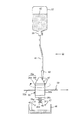
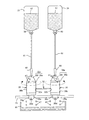
図2は図1に示す側縁塗布部の拡大図、図3は図2におけるIII方向から見た部分拡大図である。
図2および図3に示すようにこの例のインクジェット染色装置1における側縁塗布部34は、面塗布部33の搬出部11から搬出されてきたウェビング32の搬送経路に配設されている。この側縁塗布部34は、一対の塗布ローラ35,36、2つのインク液貯留容器37,38、2つの開閉弁39,40、2本の可撓性の配管(チューブ)41,42、2つのノズル43,44、1本の円柱状または円筒状のガイド45、および回収容器46を備える。
図2および図3に示すようにこの例のインクジェット染色装置1における側縁塗布部34は、面塗布部33の搬出部11から搬出されてきたウェビング32の搬送経路に配設されている。この側縁塗布部34は、一対の塗布ローラ35,36、2つのインク液貯留容器37,38、2つの開閉弁39,40、2本の可撓性の配管(チューブ)41,42、2つのノズル43,44、1本の円柱状または円筒状のガイド45、および回収容器46を備える。
各塗布ローラ35,36はまったく同じ構成を有している。各塗布ローラ35,36は、それぞれ各ローラ本体35a,36aと、各ローラ本体35a,36aに固定された各塗布部材35b,36bと、被支持部35c,36cと、固定ねじ35d,36dとを有する。各ローラ本体35a,36aは、それぞれ各被支持部35c,36cに突設された回転軸(不図示)に回転可能に支持されている。また、各ローラ本体35a,36aは、それぞれ円筒状部35e,36eとそれらの上端部に形成された截頭円錐台形状部(または円錐形状部)35f,36fから構成されている。
また、各塗布部材35b,36bはインク液を含浸するインク液の含浸性を有するフェルトや発泡材等の薄いシート状の比較的柔らかいインク液含浸部材から形成されている。これらの塗布部材35b,36bは、それぞれ各ローラ本体35a,36aの円筒状部35e,36eの外周面に巻かれて固定されている。更に、各被支持部35c,36cはそれぞれ円形の貫通孔35g,36gを有しており、これらの貫通孔35g,36gはガイド45に摺動可能に嵌合されている。その場合、ガイド45はウェビング32の搬送方向と直交する方向またはほぼ直交する方向に延設されている。したがって、各塗布ローラ35,36はガイド45にガイドされてウェビング32の搬送方向と直交する方向またはほぼ直交する方向に移動可能であり、互いに接近および離間可能にされている。
各塗布ローラ35,36は、それぞれガイド45の任意の所定位置に各固定ねじ35d,36dで固定可能とされている。その場合、図3に示すように各塗布ローラ35,36は、それらの塗布部材35b,36bが搬出部11から搬出されたウェビング32の両側縁32a,32bに比較的弱く当接するように位置決めされて固定される。そして、ウェビング32の両側縁32a,32bがそれぞれ各塗布部材35b,36bに当接した状態でウェビング32が移動すると、各塗布ローラ35,36は、このウェビング32の移動に連動して連れ回りするようにされている。
各インク液貯留容器37,38は、それぞれウェビング32に塗布するインク液47を貯留する。その場合、各インク液貯留容器37,38には、それぞれインク液の所望の色に応じて同じ色または異なる色のインク液47が貯留されている。また、各開閉弁39,40は手動で開閉可能とされているとともに、各配管(チューブ)41,42は、それぞれ各開閉弁39,40が開かれたときに各インク液貯留容器37,38内のインク液47を各ノズル43,44に供給する。その場合、各開閉弁39,40は開弁量が調整可能とされており、所望の量のインク液47を各ノズル43,44に供給可能となっている。更に、各ノズル43,44は、それぞれ供給されたインク液47を截頭円錐台形状部(または円錐形状部)35f,36f上に滴下または流下させる。更に、回収容器46は、各截頭円錐台形状部(または円錐形状部)35f,36f上に滴下または流下されたインク液のうち、各塗布部材35b,36bに含浸されない余剰のインク液を回収して貯留する。
更に、図1に示すようにインクジェット染色装置1は、側縁塗布部34よりウェビング32の搬送方向下流側に配設されたテンションローラー48および搬送ローラ49,50を有する。テンションローラー48は搬出部11から搬出されたウェビング32にテンションを付与してウェビング32をその長手方向に緊張させる。また、各搬送ローラ49,50は、側縁塗布部34を通過したウェビング32をインクジェット染色装置1の近傍の所定位置に用意された搬送台車51に搬送する。そして、搬送されたウェビング32は搬送台車51に収納される。更に、搬送台車51は収納されたウェビング32をこのウェビング32に対する次の工程に搬送する。
このように構成されたこの例のインクジェット染色装置1においては、各塗布ローラ35,36の塗布部材35b,36bが搬出部11から搬出されたウェビング32の両側縁32a,32bに比較的弱く当接可能に位置決めされて固定される。また、各開閉弁39,40が開かれて、各インク液貯留容器37,38内の所定量のインク液47がそれぞれ各ノズル43,44から各塗布ローラ35,36の截頭円錐台形状部35f,36f上に滴下または流下される。截頭円錐台形状部35f,36f上に滴下または流下されたインク液47は、それぞれ截頭円錐台形状部35f,36fの傾斜面および各ローラ本体35a,36aの外周面に沿って流下して各塗布部材35b,36bに含浸される。各塗布部材35b,36bに含浸されたインク液47以外の余剰のインク液47は回収容器46内に落下して貯留し、回収される。
この状態で、前述の従来と同様にウェビング32が表裏両面にインク液47が塗布された後、搬出部11から搬出される。このとき、搬出されたウェビング32は側縁塗布部34を通過してテンションローラ42に搬送され、テンションローラ42によってウェビング32の長手方向にテンションが付与されて緊張される。この状態で、ウェビング32が移動することで各塗布ローラ35,36がウェビング32の移動の連れ回りで回転する。そして、各塗布ローラ35,36の回転により、截頭円錐台形状部35f,36f上に滴下または流下されたインク液47は各ローラ本体35a,36aの円周方向にも流動し、各ローラ本体35a,36aの外周面の全周にわたって広がりながら流下する。これにより、インク液が各塗布部材35b,36bの全体に含浸されるようになる。このようにして、側縁塗布部34によるウェビング32の両側縁32a,32bへのインク液47の塗布が実質的に開始される。
すなわち、搬出部11から搬出されたウェビング32は側縁塗布部34に到達すると、ウェビング32の両側縁32a,32bが各塗布部材35b,36bに弱く当接する。すると、各塗布部材35b,36bに含浸されているインク液47がウェビング32の両側縁32a,32bに塗布される。このとき、搬出部11から搬出されたウェビング32がテンションローラ42によって長手方向に緊張されているため、ウェビング32は、その両側縁32a,32bが各塗布部材35b,36bに弱く当接しても幅方向に撓むことはない。したがって、各塗布部材35b,36bによってインク液がウェビング32の両側縁32a,32bに安定して十分に塗布される。
搬出部11から搬出されて表裏両面にインク液47が塗布されたウェビング32は、側縁塗布部34を通過して更に両側縁32a,32bにインク液47が塗布された後、搬送ローラ49,50により搬送台車51に搬送されて収容される。所定量のウェビング32がインク液塗布工程が終了して搬送台車51に収容されると、このウェビング32は搬送台車51により次の工程が行われる場所に搬送される。
なお、ウェビング32の両側縁32a,32bにインク液47を塗布する必要がない場合には、側縁塗布部34の両塗布ローラ35,36は互いに大きく離間されて、各塗布ローラ35,36の塗布部材35b,36bがウェビング32の両側縁32a,32bに当接しないように位置決めされる。また、ウェビング32の両側縁32a,32bのうち一方の側縁にインク液47を塗布するが他方の側縁にインク液47を塗布する必要がない場合には、両塗布ローラ35,36のうち、一方の側縁に対応する塗布ローラはその塗布部材がウェビング32の一方の側縁に弱く当接する位置に位置決めされ、また他方の側縁に対応する塗布ローラはその塗布部材がウェビング32の一方の側縁に当接しない位置に位置決めされる。
更に、回収容器46内に回収されたインク液47は各インク液貯留容器37,38に戻されて再利用される。また、各インク液貯留容器37,38内のインク液47が所定量以下に減少したときは、新たなインク液47が各インク液貯留容器37,38内の補充可能とされている。あるいは、各インク液貯留容器37,38内のインク液47がなくなった時には、各インク液貯留容器37,38をインク液47が充填されている新しいインク液貯留容器と交換可能とされている。
この例のインクジェット染色装置1によれば、面塗布部33と側縁塗布部34が配設される。したがって、面塗布部33の搬出部11から搬出されて表裏両面にインク液47が塗布されたウェビング32の両側縁32a,32bに、側縁塗布部34の一対の塗布ローラ35,36によってインク液47を塗布することが可能となる。その場合、ウェビング32の両側縁32a,32bへのインク液の塗布に、一対の塗布ローラが用いられることにより、ウェビング32の両側縁32a,32bにインク液を塗布する側縁塗布部34の構造を簡単に形成することができる。
また、面塗布部33の搬出部11から搬出されたウェビング32はテンション部材であるテンションローラ48でウェビング32の長手方向にテンションが付与されるので、ウェビング32の両側縁32a,32bが各塗布部材35b,36bに弱く当接してもウェビング32がその幅方向(長手方向と直交する方向)に撓むことを防止できる。したがって、各塗布部材35b,36bによってインク液47をウェビング32の両側縁32a,32bに安定して十分に塗布することが可能となる。
更に、各塗布ローラ35,36が、それぞれインク液が含浸されたシート状の塗布部材35b,36bを有している。これにより、ウェビング32の両側縁32a,32bにインク液を塗布する塗布部材35b,36bを安価にかつ簡単に形成することができる。
更に、各塗布ローラ35,36は位置調整可能に配設されるので、ウェビング32の両側縁32a,32bの少なくとも一方の側縁にインク液を塗布する必要がない場合には、インク液を塗布する必要がない側縁に対応する塗布ローラを、その塗布部材がこの側縁に当接しないように位置決めすることができる。これにより、ウェビング32の側縁へのインク液の塗布に対して、柔軟に対応することが可能となる。
更に、各塗布ローラ35,36はウェビング32の移動に連動して連れ回りで回転するようにしているので、各塗布ローラ35,36を回転駆動するためのモータや電磁ソレノイド等の駆動源が不要となる。これにより、側縁塗布部34の構造を簡略化することが可能になるとともにコストを低減することができる。
更に、各塗布ローラ35,36の各ローラ本体35a,36aの上端部が截頭円錐台形状部(または円錐形状部)35f,36fとされているので、截頭円錐台形状部(または円錐形状部)35f,36fに滴下あるいは流下したインク液47を、各塗布ローラ35,36を回転させることで、各ローラ本体35a,36aの外周面の全周にわたって広がりながら流下させることができる。これにより、インク液を各塗布部材35b,36bの全体に効果的にかつ簡単に含浸させることが可能となる。
更に、この例のインクジェット染色装置1によりウェビング32の表裏両面およびウェビング32の両側縁32a,32bのいずれにもインク液47を塗布することで、種々の色のシートベルト4や種々の模様のシートベルト4を形成することができ、シートベルト4に対するユーザーの様々な要望に柔軟対応することが可能となる。
なお、本発明は前述の例に限定されるものではなく、種々設計変更可能である。例えば、開閉弁39,40を手動の開閉弁にしているが電磁開閉弁で構成することもできる。この場合には、電磁開閉弁の開閉制御および開弁量制御は制御部31で行うようにする。また、ガイド45に雄ねじを形成するとともに、塗布ローラ35,36における被支持部35c,36cの貫通孔35g,36gの内周面にガイド45の雄ねじが螺合する雌ねじを形成し、モータや電磁ソレノイド等の駆動源でガイド45を回転することにより、塗布ローラ35,36の位置調整を行うようにすることもできる。その場合に、塗布ローラ35側のねじと塗布ローラ36側のねじとは互いに逆ねじに形成することにより、両塗布ローラ35,36を互いに接近させたりあるいは離間させたりすることが可能となる。この場合のガイド45を回転させる駆動源の駆動制御も、制御部31で行うようにする。
更に、前述の例では本発明の帯状生地の染料液塗布装置を特許文献1の図5に記載されているインクジェット染色装置に適用するものとしているが、これに限定されることはなく、本発明は特許文献1の他の図に記載されているインクジェット染色装置にも適用することができる。更には、本発明は特許文献1に記載のインクジェット染色装置以外の帯状生地の表裏両面の少なくとも一方の面に染料液を塗布する装置であればどのような装置にも適用することができる。要は、本発明は特許請求の範囲に記載された技術事項の範囲で種々設計変更が可能である。
本発明に係る帯状生地の染料液塗布装置は、自動車等の車両に装備されるシートベルト装置に用いられて乗員を拘束するウェビング等の細長い帯状生地に染料液を塗布する染料液塗布装置に好適に利用することができる。
Claims (7)
- 帯状生地を搬入する搬入部と、
前記搬入部から搬入された前記帯状生地の両面の少なくとも一方の面に染料液を塗布する面塗布部と、
前記面塗布部で前記帯状生地の両面の少なくとも一方の面に染料液を塗布された前記帯状生地を搬出する搬出部と、
前記搬出部から搬出された前記帯状生地の両側縁の少なくとも一方の側縁に染料液を塗布する側縁塗布部と、
を有することを特徴とする帯状生地の染料液塗布装置。 - 前記側縁塗布部は、前記搬出部から搬出された前記帯状生地の各側縁にそれぞれ当接および離間するように位置調整可能であるとともに前記染料液を前記帯状生地の各側縁に塗布するように回転可能な一対の塗布ローラを有することを特徴とする請求項1に記載の帯状生地の染料液塗布装置。
- 前記一対の塗布ローラは、それぞれ前記染料液が含浸されたシート状の塗布部材を有することを特徴とする請求項2に記載の帯状生地の染料液塗布装置。
- 前記一対の塗布ローラは、前記帯状生地の移動に連動して連れ回りで回転することを特徴とする請求項2または3のいずれか1項に記載の帯状生地の染料液塗布装置。
- 前記一対の塗布ローラは、それぞれそれらの上端部が截頭円錐台形状部または円錐形状部とされており、
前記截頭円錐台形状部または前記円錐形状部に前記染料液が滴下あるいは流下されることを特徴とする請求項2ないし4のいずれか1項に記載の帯状生地の染料液塗布装置。 - 前記搬出部から搬出された前記帯状生地に、前記帯状生地の長手方向にテンションを付与するテンション部材を有することを特徴とする請求項1ないし5のいずれか1項に記載の帯状生地の染料液塗布装置。
- 前記帯状生地は、シートベルト用ウェビングであることを特徴とする請求項1ないし6のいずれか1項に記載の帯状生地の染料液塗布装置。
Applications Claiming Priority (2)
| Application Number | Priority Date | Filing Date | Title |
|---|---|---|---|
| JP2010-290012 | 2010-12-27 | ||
| JP2010290012A JP5730007B2 (ja) | 2010-12-27 | 2010-12-27 | 帯状生地の染料液塗布装置 |
Publications (1)
| Publication Number | Publication Date |
|---|---|
| WO2012090396A1 true WO2012090396A1 (ja) | 2012-07-05 |
Family
ID=46382540
Family Applications (1)
| Application Number | Title | Priority Date | Filing Date |
|---|---|---|---|
| PCT/JP2011/006791 Ceased WO2012090396A1 (ja) | 2010-12-27 | 2011-12-05 | 帯状生地の染料液塗布装置 |
Country Status (2)
| Country | Link |
|---|---|
| JP (1) | JP5730007B2 (ja) |
| WO (1) | WO2012090396A1 (ja) |
Cited By (1)
| Publication number | Priority date | Publication date | Assignee | Title |
|---|---|---|---|---|
| CN110273238A (zh) * | 2019-08-01 | 2019-09-24 | 烟台骄阳针织有限公司 | 一种柔性厚面料内外双面染色机 |
Families Citing this family (1)
| Publication number | Priority date | Publication date | Assignee | Title |
|---|---|---|---|---|
| JP7631803B2 (ja) * | 2020-12-28 | 2025-02-19 | セイコーエプソン株式会社 | 印刷装置、印刷システムおよび印刷装置の印刷方法 |
Citations (4)
| Publication number | Priority date | Publication date | Assignee | Title |
|---|---|---|---|---|
| JPS6399384A (ja) * | 1986-10-09 | 1988-04-30 | 東京整理染色株式会社 | 染色装置 |
| WO1998011292A1 (en) * | 1996-09-13 | 1998-03-19 | Kikuchi Web Tech Co., Ltd. | Band-like cloth processing apparatus |
| JPH11140768A (ja) * | 1997-11-11 | 1999-05-25 | Nishi Nenshi Kk | 糸状側面の部分染糸 |
| JP2010053497A (ja) * | 2008-08-29 | 2010-03-11 | Takata Corp | インクジェット染色方法及び装置 |
-
2010
- 2010-12-27 JP JP2010290012A patent/JP5730007B2/ja active Active
-
2011
- 2011-12-05 WO PCT/JP2011/006791 patent/WO2012090396A1/ja not_active Ceased
Patent Citations (4)
| Publication number | Priority date | Publication date | Assignee | Title |
|---|---|---|---|---|
| JPS6399384A (ja) * | 1986-10-09 | 1988-04-30 | 東京整理染色株式会社 | 染色装置 |
| WO1998011292A1 (en) * | 1996-09-13 | 1998-03-19 | Kikuchi Web Tech Co., Ltd. | Band-like cloth processing apparatus |
| JPH11140768A (ja) * | 1997-11-11 | 1999-05-25 | Nishi Nenshi Kk | 糸状側面の部分染糸 |
| JP2010053497A (ja) * | 2008-08-29 | 2010-03-11 | Takata Corp | インクジェット染色方法及び装置 |
Cited By (2)
| Publication number | Priority date | Publication date | Assignee | Title |
|---|---|---|---|---|
| CN110273238A (zh) * | 2019-08-01 | 2019-09-24 | 烟台骄阳针织有限公司 | 一种柔性厚面料内外双面染色机 |
| CN110273238B (zh) * | 2019-08-01 | 2020-06-26 | 浙江耐力拉链有限公司 | 一种柔性厚面料内外双面染色机 |
Also Published As
| Publication number | Publication date |
|---|---|
| JP2012136805A (ja) | 2012-07-19 |
| JP5730007B2 (ja) | 2015-06-03 |
Similar Documents
| Publication | Publication Date | Title |
|---|---|---|
| US7588639B2 (en) | Liquid applying apparatus and ink jet printing apparatus | |
| US8038268B2 (en) | Liquid applying apparatus and ink jet printing apparatus | |
| US8764160B2 (en) | Liquid treatment agent coating device for inkjet printer, method of operating liquid treatment agent coating device, and image forming system | |
| US7270409B2 (en) | Liquid applying apparatus and ink jet printing apparatus | |
| US8087744B2 (en) | Ink jet printing apparatus | |
| EP3263345B1 (en) | Printing apparatus and printing method | |
| JP5817438B2 (ja) | インクジェットプリンタ用処理剤液塗布装置および画像形成システム | |
| JP5730007B2 (ja) | 帯状生地の染料液塗布装置 | |
| KR20070110209A (ko) | 이동 웹에 액체를 도포하기 위한 액체 도포 장치 | |
| WO2014111462A1 (en) | Printing apparatus for printing on a print substrate | |
| US11040542B2 (en) | Inkjet printer with dual cleaning units | |
| JP7807455B2 (ja) | エアバー、乾燥装置、及びインクジェット印刷装置 | |
| JP2023093917A (ja) | 液体吐出ユニット、液体吐出装置および線状媒体処理システム | |
| DE102012023389A1 (de) | Verfahren zum Reinigen eines Zwischenträgers für den indirekten Druck | |
| JP6852282B2 (ja) | 液体吐出装置 | |
| JP7714886B2 (ja) | 前処理装置、前処理装置の前処理方法および印刷装置 | |
| JP2006346534A (ja) | 液体塗布装置及び記録装置 | |
| JP6213008B2 (ja) | インクジェットプリンタ用処理剤液塗布装置 | |
| JP7771593B2 (ja) | 捺染装置 | |
| JP2005254809A (ja) | 液体塗布装置およびインクジェット記録装置 | |
| JP2009226919A (ja) | 記録装置 | |
| WO2024247709A1 (ja) | 印刷装置 | |
| KR200382586Y1 (ko) | 로울러 및 분사날염을 동시에 하는 날염기 | |
| JP4508978B2 (ja) | 液体塗布装置およびインクジェット記録装置 | |
| JP2007000778A (ja) | 液体塗布装置および記録装置 |
Legal Events
| Date | Code | Title | Description |
|---|---|---|---|
| 121 | Ep: the epo has been informed by wipo that ep was designated in this application |
Ref document number: 11853665 Country of ref document: EP Kind code of ref document: A1 |
|
| NENP | Non-entry into the national phase |
Ref country code: DE |
|
| 122 | Ep: pct application non-entry in european phase |
Ref document number: 11853665 Country of ref document: EP Kind code of ref document: A1 |