WO2012086766A1 - 不織布の製造方法、不織布および不織布の製造装置並びに不織布製造用支持体 - Google Patents
不織布の製造方法、不織布および不織布の製造装置並びに不織布製造用支持体 Download PDFInfo
- Publication number
- WO2012086766A1 WO2012086766A1 PCT/JP2011/079840 JP2011079840W WO2012086766A1 WO 2012086766 A1 WO2012086766 A1 WO 2012086766A1 JP 2011079840 W JP2011079840 W JP 2011079840W WO 2012086766 A1 WO2012086766 A1 WO 2012086766A1
- Authority
- WO
- WIPO (PCT)
- Prior art keywords
- web
- hot air
- support
- nonwoven fabric
- fibers
- Prior art date
- Legal status (The legal status is an assumption and is not a legal conclusion. Google has not performed a legal analysis and makes no representation as to the accuracy of the status listed.)
- Ceased
Links
Images


Classifications
-
- D—TEXTILES; PAPER
- D04—BRAIDING; LACE-MAKING; KNITTING; TRIMMINGS; NON-WOVEN FABRICS
- D04H—MAKING TEXTILE FABRICS, e.g. FROM FIBRES OR FILAMENTARY MATERIAL; FABRICS MADE BY SUCH PROCESSES OR APPARATUS, e.g. FELTS, NON-WOVEN FABRICS; COTTON-WOOL; WADDING ; NON-WOVEN FABRICS FROM STAPLE FIBRES, FILAMENTS OR YARNS, BONDED WITH AT LEAST ONE WEB-LIKE MATERIAL DURING THEIR CONSOLIDATION
- D04H1/00—Non-woven fabrics formed wholly or mainly of staple fibres or like relatively short fibres
- D04H1/40—Non-woven fabrics formed wholly or mainly of staple fibres or like relatively short fibres from fleeces or layers composed of fibres without existing or potential cohesive properties
- D04H1/54—Non-woven fabrics formed wholly or mainly of staple fibres or like relatively short fibres from fleeces or layers composed of fibres without existing or potential cohesive properties by welding together the fibres, e.g. by partially melting or dissolving
Definitions
- the present invention relates to a method for producing a nonwoven fabric, a nonwoven fabric obtained from the method, a nonwoven fabric production apparatus, and a nonwoven fabric production support.
- a fiber web containing thermoplastic fibers is passed between a pair of breathable conveyors having at least one unevenness, and the fiber web is conveyed between the conveyors.
- This breathable conveyor with unevenness has a plurality of triangular helical wires, insert another triangular helical wire adjacent between the spirals of the triangular helical wire, and the adjacent triangular helical wires
- a fluid mainly composed of a gas is sprayed on a fiber assembly formed in a substantially sheet shape with the fibers having a degree of freedom, and 1 or 2 of predetermined grooves, openings, or protrusions.
- a predetermined spraying means sprays a fluid mainly composed of gas from the other surface side of the fiber assembly to move and separate the fibers, so that a groove, an opening, a protrusion, etc. Form.
- the nonwoven fabric is formed by heat-sealing the thermoplastic fibers contained in the fiber assembly by heat treatment with a predetermined heating device while maintaining the uneven shape (see, for example, Patent Document 2).
- Patent Document 3 discloses a method of pressing the tip of the fluff protruding from the web surface with a hot roll. In this production method, by adjusting the coefficient of friction of the surface of the nonwoven fabric by changing the temperature, rotation speed, and pressure of the heat roll, a nonwoven fabric with excellent liquid permeability, less irritation to the skin, and increased softness can be obtained.
- Patent Document 4 discloses a technique for performing a so-called smoothing process in which a top sheet is sandwiched between two rollers and pressure is applied to the surface of the air-through nonwoven fabric so that fluffy fibers are laid down on the surface. Furthermore, a method for cutting and smoothing fuzzed fibers is also disclosed. Further, Patent Document 5 discloses a technique for pressing down a protruding fiber tip so as to lie down by applying pressure through an air-through non-woven fabric between heat rollers and thermally melting it.
- fuzzed fibers on the surface of the nonwoven fabric are heated, but internal fibers are not heated. In this state, the fibers are not fused even if the fluff is pushed inside. Therefore, fluffing may occur again when external force is applied. Further, when the hot roll temperature is increased, the fusion strength is increased, but the voids are extremely reduced by heating, and the liquid permeability may be impaired. On the other hand, in the method of cutting fuzz, the fuzz is eliminated by the cut, but a fiber having no fused portion is generated, which may cause a problem of short fiber dropping.
- a support for supporting a shaped fiber web used in a conventional method for producing a nonwoven fabric As a support for supporting a shaped fiber web used in a conventional method for producing a nonwoven fabric, a support having a large number of projections scattered on a continuous smooth surface and a plurality of small through holes in a plane between the projections. It is disclosed.
- a fiber web is placed on the support, and a high-speed water stream is sprayed onto the fiber web to distribute the fibers on the protrusions and simultaneously provide openings.
- a perforated nonwoven fabric is produced by entanglement of fibers on the smooth surface. (For example, refer to Patent Document 6).
- the method for producing a nonwoven fabric disclosed in Patent Document 6 uses water as an energy to move and shape the fibers in the web, so that the portion corresponding to the protrusion of the support is opened. Although a non-woven fabric can be obtained, too much energy is applied, so that a non-woven fabric having a high fiber density, that is, a thin thickness can be obtained.
- air is blown into the fiber web and pushed into the support used in the method described in Patent Document 1
- the fibers of the fiber web contact on the back side through the small through holes of the support, and hot air is applied in that state.
- the fibers are fused and entangled with the small through holes interposed therebetween. For this reason, it becomes difficult to peel off the fiber web from the support, and fluffing or poor appearance can be achieved.
- each small through hole is as small as 1.0 mm to 2.0 mm and scattered in the flat portion, air hardly converges on the small through hole. For this reason, the air blown to the area
- JP-A-2-229255 JP 2008-2034 A Japanese Patent Laid-Open No. 2003-235896 JP 2003-265520 A JP 2003-265528 A JP-A 62-69867
- the fiber web is excellent in formability without disturbing the fibers of the fiber web and preventing fusion and entanglement of the fibers through the holes arranged in the support. It is an object of the present invention to provide a non-woven fabric production support and a method for producing a non-woven fabric using the support.
- the present invention manufactures a nonwoven fabric that conveys a web containing thermoplastic fibers onto a support having an uneven shape, and blows hot air from the top of the web toward the support to shape the uneven shape on the web.
- a method A step of temporarily fusing the web fibers with the first hot air so that the uneven shape is maintained, and a state where the second hot air having a temperature higher than the first is blown to maintain the uneven shape.
- fixing the concavo-convex shape by fusing together the fibers of the web, and solving the above problems by a method of manufacturing a nonwoven fabric by shaping the concavo-convex shape on the web along the web It is.
- the present invention relates to a method for producing a nonwoven fabric in which a fiber web containing thermoplastic fibers is conveyed on a breathable support having an uneven shape, and hot air is blown to shape the uneven shape on the fiber web.
- air through refers to a state in which a fiber web is disposed on the surface of a breathable support, a gas is blown from the fiber web side, and the gas passes through the fiber web and the breathable support. The process which blows through to the back surface side of a breathable support body.
- the present invention solves the above problems by the nonwoven fabric produced by the above-described method for producing a nonwoven fabric of the present invention.
- the present invention includes a support having a projecting portion and a ventilation portion, and transporting a web containing thermoplastic fibers on the surface having the projecting portion, and the web is placed along the support.
- a non-woven fabric manufacturing apparatus comprising a nozzle for blowing hot air, and forming a concavo-convex shape on the web, wherein the nozzle has a first nozzle for blowing the first hot air and a temperature higher than that of the first hot air.
- the two nozzles solve the above problems by a manufacturing apparatus that fixes the uneven shape by fusing the fibers of the web with the uneven shape held by blowing the second hot air.
- the present invention relates to an air-through type support that conveys a fiber web containing thermoplastic fibers on a surface having an uneven shape, and hot air is blown to the fiber web that is conveyed to the surface of the support.
- a nozzle for shaping the web, a cooling section for cooling the shaped fiber web to a temperature lower than the melting point of the thermoplastic fiber, and fuzzed fibers and other fibers are fused to the cooled fiber web.
- the present invention has a plate-like body, a plurality of protrusions arranged on the surface of the plate-like body, and a plurality of holes penetrating from the surface to the back surface facing the surface, the protrusions and the holes Are alternately arranged in a first direction on the surface and in a second direction perpendicular thereto, and the projections are arranged at a predetermined interval, and the projections have a first surface and a second surface facing each other.
- the present invention is surrounded by a plurality of rod-shaped bodies arranged in parallel, a plurality of protrusions disposed between the rod-shaped bodies, and the protrusions adjacent to each other between the adjacent rod-shaped bodies and in the longitudinal direction of the rod-shaped body.
- the projections and the holes are alternately arranged in a first direction and a second direction orthogonal thereto, and the projections are arranged at a predetermined interval, and the projections are opposed to each other.
- a web containing thermoplastic fibers is conveyed onto a support having a plurality of protrusions and a plurality of holes, and hot air is blown to the fiber web along the support.
- a plurality of holes penetrating the back surface wherein the protrusions and the holes are alternately arranged in a first direction on the surface and in a second direction perpendicular thereto, and the protrusions are arranged at a predetermined interval;
- a fiber web containing thermoplastic fibers is transported onto a support having a plurality of protrusions and a plurality of holes, and hot air is blown to the fiber web along the support.
- a method of manufacturing a shaped nonwoven fabric that forms a concavo-convex shape on a web wherein the support is provided with a plurality of rod-like bodies arranged in parallel, a plurality of protrusions arranged between the rod-like bodies, and the adjacent A hole existing in a region surrounded by the protrusions adjacent to each other in the longitudinal direction of the rod-shaped body, and the protrusion and the hole have a first direction and a second direction perpendicular thereto.
- the projections are alternately arranged at predetermined intervals, and the projections solve the above problems by a method for manufacturing a shaped nonwoven fabric using a first surface and a second surface facing each other. .
- the nonwoven fabric manufacturing method of the present invention shapes the fibers of the web into the concavo-convex shape of the support having the concavo-convex surface by spraying the first hot air, and performs the temporary fusion while maintaining the state. It is difficult for the fibers caught in the concave portions between the convex portions of the support to return. After the temporary fusing, the fibers are in this state and are fused and fixed by blowing the next second hot air, so that the web fibers are supported by the fact that the web fibers are softened by heat. It becomes easy to follow the shape of the convex part of the body, and the retainability of the uneven shape is improved. As a result, it is possible to obtain a low density and bulky nonwoven fabric with high formability.
- the temporary fusion means that the fibers of the web are pressed to the concavo-convex portion of the support by blowing hot air as described above and the fibers pressed to the concave portion are hardly returned to each other.
- the temporarily fused state of the fibers at that time is maintained up to a position where the second hot air is blown by the support. Accordingly, the temporary fusion is different from the fusion by blowing the second hot air in that the uneven shape is not fixed by fusing the fibers by fusing the fibers together.
- the fibers in the method for producing a nonwoven fabric of the present invention, by cooling a fiber web formed by hot-air air-through blowing, the fibers can be firmly fused and the network structure of the fibers can be strengthened. In that state, the hot air is sufficiently blown and heated to the fluff fibers by air-through, so that the fluff fibers can be softened and brought into contact with other fibers (fibers of the network structure). Since the fibers are fused to each other, the fuzzed fibers can be fixed in a lying state. As a result, fluffing can be reduced, and even when an external force is applied to the surface of the nonwoven fabric, it becomes difficult to fluff, and a nonwoven fabric with a smooth feel can be obtained. Further, since the shaped shape is fixed when fuzzing fibers are fused, excessive fusion does not occur in other fibers, so that a non-woven fabric having a sufficient thickness and voids and excellent liquid permeability can be provided.
- the nonwoven fabric of this invention is a nonwoven fabric manufactured by said special manufacturing process, it becomes a low density and bulky nonwoven fabric shape
- the nonwoven fabric manufacturing apparatus of the present invention can temporarily fuse the fibers of the web so that the uneven shape is maintained by blowing the first hot air with the first nozzle. For this reason, it is difficult for the fibers of the web that are trapped between the protrusions of the support to return. In this state, the second hot air is blown by the second nozzle so that the fibers of the web can be fused together, so that the concavo-convex shape can be maintained and fixed. Further, since the hot air is blown, the fibers of the web are softened by heat, and it becomes easy to follow the shape of the protruding portion of the support, and the retention of the uneven shape is improved. As a result, a low-density and bulky nonwoven fabric excellent in formability as described above can be obtained.
- the nonwoven fabric production apparatus of the present invention is a suitable apparatus for carrying out the above-described nonwoven fabric production method.
- a cooling part that cools the shaped fiber web by blowing hot air with the air-through method By arranging a cooling part that cools the shaped fiber web by blowing hot air with the air-through method, the intersection of the fused fibers is firmly fixed, and the network structure of the fibers is solid Since it can do, the uneven
- any of the nonwoven fabric production supports of the present invention and the method for producing a shaped nonwoven fabric using the support comprises disturbing the fibers of the fiber web by the blown air in the shaping treatment for forming irregularities on the fiber web. And there is no fusion or entanglement between the fibers through the holes in the support. Therefore, the three-dimensional uneven nonwoven fabric is excellent in formability of the fiber web and can be formed into a nonwoven fabric having a small weight per unit area (density) and an effective thickness (less liquid residue when used in an absorbent body). Enable production.
- first embodiment of the nonwoven fabric production method and production apparatus according to the present invention, refer to the schematic configuration diagram of the nonwoven fabric production apparatus shown in FIG. 1 and the partially enlarged view of the support shown in FIG. However, it will be described below.
- the nonwoven fabric manufacturing apparatus 1 preferably used for carrying out the nonwoven fabric manufacturing method according to the present invention will be described.
- the nonwoven fabric manufacturing apparatus 1 has a support 10 that transports a web 60 (hereinafter also referred to as a fiber web) containing thermoplastic fibers.
- the web 60 is supplied to the surface of the support 10 by a feed conveyor as the feed unit 21, and the shaped web 60 is fed from the support 10 by a guide roller as the guide unit 22 in a predetermined direction.
- the support 10 has, for example, a drum shape, and has a plurality of protruding portions 10T that are concave and convex portions and a plurality of ventilation portions 10H that are concave portions on the surface thereof.
- the protruding portions 10T and the ventilation portions 10H are alternately arranged in the longitudinal and lateral directions of the support 10.
- the support body 10 is rotatable around the rotation shaft 10C.
- a driving device (not shown) is connected to the rotating shaft 10C.
- the protruding portion 10T has a shape that tapers toward the tip, and the tip has a round shape, for example, a plate shape, a spindle shape, or the like. The height varies depending on the use, standard, etc.
- the protrusion pitch is 6 mm to 15 mm in the MD direction, and 4 mm to 8 mm in the CD direction. It is as follows.
- the MD direction is the feeding direction of the web 60
- the CD direction is a direction perpendicular to the MD direction on the surface of the support 10. If the height of the protrusion 10T is too low, sufficient unevenness cannot be formed on the web 60. If the height is too high, the protrusion 10T may penetrate the web 60 when hot air is blown. There is. Therefore, the protruding portion 10T is appropriately set within the above range.
- it is formed at a height of 3 mm or more and 10 mm or less, is arranged in the MD direction at 6 mm or more and 10 mm or less, and is arranged in the CD direction at 4 mm or more and 6 mm or less.
- the ventilation portion 10H is composed of a plurality of openings formed in the support 10, and the opening ratio is set to 20% or more and 45% or less with respect to the surface area of the support 10. If the opening ratio is less than 20%, it becomes difficult to form a sufficient uneven shape on the web 60. If the opening ratio exceeds 45%, the web 60 moves below the support 10 when hot air is blown. It becomes difficult to peel off from the support 10, and there is a possibility that the shaped shape is deteriorated and fluff is likely to be formed. Therefore, the aperture ratio is set.
- the aperture ratio is preferably 10% to 50%, more preferably 15% to 40%, still more preferably 20% to 35%, and particularly preferably 30% to 35%.
- the support 10 is rotated to convey the web 60 so that the web 60 is hooked by the protruding portion 10T on the surface side having the protruding portion 10T.
- the first nozzle 11 that blows the first hot air W ⁇ b> 1 and the second hot air W ⁇ b> 2 that blows the second hot air W ⁇ b> 2 in order along the supply direction of the web 60 on the outside where the protruding portion 10 ⁇ / b> T of the support 10 is formed.
- a nozzle 12 is provided.
- the first nozzle 11 includes a heater 13, and the first hot air W1 heated by the heater 13 is passed through a ventilating conveyor 23 having air permeability to the surface of the support 10 on which the protruding portion 10T is disposed. For example, spray almost vertically.
- the spray hole of the first nozzle 11 preferably has a length in the MD direction of 1 mm or more and 20 mm or less, and the length in the CD direction is a web width or more, or a width for shaping.
- the spray holes have a single or multi-row slit shape, and a single or multi-row round hole, long hole, and square hole arranged in a staggered manner or in parallel.
- the first hot air W1 has a slit shape in a row of 2 mm or more and 20 mm or less.
- the first hot air W1 is blown at a uniform wind speed in the width direction of the surface of the web 60.
- air, nitrogen or water vapor heated to a predetermined temperature by the heater 13 can be used.
- air that does not cost is used.
- the first hot air W ⁇ b> 1 blown from the first nozzle 11 is controlled by the heater 13 to a temperature at which the fibers of the web 60 are temporarily fused so that the uneven shape is maintained.
- the first hot air W1 is 60 ° C. higher than the melting point of the low melting point component of the web 60 fiber.
- the hot air is controlled to a temperature not lower than the low temperature and not higher than 15 ° C. higher than the melting point of the low melting point component.
- the temperature is controlled to be not less than 50 ° C lower than the melting point of the low melting point component and not more than 10 ° C higher than the melting point of the low melting point component.
- a preferable temperature range is from 82 ° C. to 142 ° C., more preferably from 132 ° C. to 142 ° C.
- the temperature of the first hot air W1 is less than 60 ° C. lower than the melting point of the low melting point component of the fiber of the web 60, the fiber returns and the formability deteriorates.
- the temperature exceeds 15 ° C. higher than the melting point of the low melting point component of the fiber of the web 60, the fibers are fused at once, and the formability is inferior due to a decrease in the degree of freedom.
- the wind speed of the first hot air W1 is adjusted as appropriate, but is preferably controlled to a wind speed of 10 m / sec or more and 120 m / sec or less. If the wind speed of the first hot air W1 blown from the first nozzle 11 is too slow, the fibers do not sufficiently follow the support and the fibers are weakly fused so that they cannot be shaped, resulting in a bulky uneven shape. On the other hand, if the wind speed is too high, the fibers of the web 60 are sorted by the protruding portions 10T, and the fibers do not have a concavo-convex shape along the shape of the support or become a perforated nonwoven fabric. Therefore, the wind speed of the first hot air W1 is preferably in the above range. More preferably, it is 20 m / sec or more and 80 m / sec or less, and particularly preferably 40 m / sec or more and 60 m / sec or less.
- the aeration conveyor 23 feeds the web 60 to the feed side along the surface of the support 10 while sandwiching the web 60 with the support 10.
- a belt 24 having air permeability, a plurality of rollers 25 that support the belt 24, and a drive device (not shown) that drives the belt 24 via the rollers 25 are provided.
- the plurality of rollers 25 at least two rollers 25 ⁇ / b> A and 25 ⁇ / b> B are arranged on the surface of the support 10 so that the belt 24 runs along the web 60.
- the ventilation conveyor 23 can prevent the web 60 from being disturbed and scattered by the first hot air W ⁇ b> 1 of the first nozzle 11.
- the second nozzle 12 includes a heater 14 and blows the second hot air W2 heated by the heater 14 to the surface of the support 10 on which the protruding portion 10T is formed, for example, substantially perpendicularly. It is desirable to use a punching metal that is regularly opened in the width direction and the flow direction as the blowing hole of the second nozzle 12.
- the open area ratio is preferably 10% or more and 40% or less, and more preferably 20% or more and 30% or less.
- the second hot air W2 is blown at a uniform wind speed in the width direction of the surface of the web 60.
- air, nitrogen or water vapor heated by the heater 14 can be used.
- air that does not cost is used.
- the second hot air W2 is controlled by the heater 14 to a temperature at which the fibers 60 of the web 60 are fused together and the uneven shape is fixed while the uneven shape of the web 60 formed by the first hot air W1 is maintained. ing.
- the second hot air W2 is higher than the melting point of the low melting point component of the web 60 fiber. It is controlled to be hot air at a temperature below the melting point of the high melting point component of 60 fibers, preferably 40 ° C. or higher than the melting point of the low melting point component.
- the melting point of the low melting point component is controlled to a temperature not higher than 20 ° C. below this melting point, and the particularly preferable temperature is not less than the melting point of the low melting point component and not higher than 15 ° C. below this melting point.
- a more preferable temperature range is from 132 ° C. to 152 ° C., particularly preferably from 132 ° C. to 147 ° C. Note that if the temperature of the second hot air W2 is lower than the melting point of the low melting point component of the fibers of the web 60, the uneven shape retainability is insufficient. On the other hand, if the temperature is higher than 180 ° C., the texture becomes worse.
- the wind speed of the second hot air W2 blown from the second nozzle 12 is appropriately determined in consideration of its purpose, but is preferably controlled to a wind speed of 1 m / sec or more and 10 m / sec or less. If the wind speed of the second hot air W2 blown from the second nozzle 12 is too slow, heat cannot be transferred to the fibers, the fibers are not fused, and the uneven shape is insufficiently fixed. On the other hand, if the wind speed is too high, the fiber will be too hot and the texture will tend to be poor. Therefore, the wind speed of the second hot air W2 is preferably in the above range. More preferably, it is 1 m / sec or more and 8 m / sec or less, and particularly preferably 2 m / sec or more and 4 m / sec or less.
- a suction unit 15 that sucks the first hot air W ⁇ b> 1 blown from the first nozzle 11 through the aeration conveyor 23, the web 60, and the support 10 is arranged.
- An exhaust device 17 for exhausting the sucked first hot air W1 is connected to the suction portion 15.
- a suction unit 16 that sucks the second hot air W ⁇ b> 2 blown from the second nozzle 12 through the web 60 and the support 10 is disposed.
- the suction unit 16 is connected to an exhaust device 18 that exhausts the sucked second hot air W2.
- any suction part can have a structure in which the length in the CD direction can be adjusted as appropriate.
- suction portions 15 and 16 By arranging such suction portions 15 and 16, it is possible to prevent the web from being disturbed by the rebound of the air to be blown, and to stably shape the web into a desired shape. Further, it is possible to prevent the temperature around the drum from becoming too high and prevent the web 60 in contact with the drum from being excessively fused and hardened. Furthermore, it becomes easy to hold the web 60 on the support body 10, and the conveyance becomes easy. In consideration of the stabilization of hot air temperature and the running cost of utilities, it is desirable to circulate and use hot air.
- the first hot air W1 can be blown by the first nozzle 11 to temporarily fuse the fibers of the web 60 to a state in which the uneven shape is maintained. For this reason, the fibers of the web 60 that are trapped between the protruding portions 10T of the support 10 are difficult to return. In this state, since the second hot air W2 is blown by the second nozzle 12, the fibers of the web 60 can be fused and fixed in a state where the uneven shape is maintained.
- the fibers of the web 60 are softened by heat, so that it becomes easy to follow the surface shape of the protruding portion 10T of the support 10 and the unevenness. Good shape retention.
- the web 60 can be more easily brought along the surface of the protruding portion 10T. As a result, a low density and bulky nonwoven fabric with good formability can be obtained.
- the web 60 is deformed and weakly fixed between fibers by the first nozzle 11 so as to follow the uneven shape of the support 10, and is thermally fused by the second nozzle 12 to be a nonwoven fabric.
- corrugated shape of the support body 10 should just be deform
- the web 60 is too along the uneven shape of the support, not only the above-mentioned influence of the deformation of the shaped shape and the formation of fuzz at the time of separation from the support 10 but also the substantial thickness of the nonwoven fabric decreases, and the fiber melts.
- the flexibility is impaired from the nonwoven fabric due to an increase in landing points, excessive fiber fusion due to contact with the support, and the like.
- the tip of the projecting portion 10T of the support 10 having the plurality of projecting portions 10T and the plurality of ventilation portions 10H and the web 60 are in direct contact with each other from the viewpoint of improving the shapeability.
- the web 60 is preferably spaced from the support 10 to form a gap from the viewpoint of flexibility of the nonwoven fabric and formation of a low density structure.
- the gap is formed on the vent portion 10H side of the protruding portion 10T, the second hot air W2 is easily penetrated in the thickness direction of the web 60, so that the hot air blowing surface side and the support 10 side are provided. Differences in the fused state of the fibers are unlikely to occur, and the bulky structure is easily recovered against deformation such as compression and tension, resulting in a non-woven fabric that is less prone to fluff. From the same viewpoint, it is more preferable that a gap is formed between the ventilation portion 10H and the web 60.
- the support 10 when the web 60 is in direct contact with the support 10, the support 10 is repeatedly warmed by each hot air, so that the fiber is excessively fused on the support 60 side surface of the web 60 and the surface becomes hard. As a result, the texture deteriorates, but the influence of the heat of the support 10 can be reduced by separating the web 60 and the support 10 by the gap.
- the apparatus configuration can be reduced in size and the area occupied by the apparatus can be reduced.
- the support body 10 is comprised in the drum shape, the fiber of the web 60 shaped rather than the conventional conveyor type support body becomes easy to peel from the protruding part 10T.
- the nonwoven fabric production apparatus 2 is the one in which the aeration conveyor 23 is continuously arranged from the blowout side of the first nozzle 11 to the blowout side of the second nozzle 12 in the nonwoven fabric production apparatus 1 described above.
- the web 60 is conveyed to the feed side along the surface of the support 10 while sandwiching the web 60 with the support 10.
- a belt 24 having air permeability, a plurality of rollers 25 that support the belt 24, and a drive device (not shown) that drives the belt 24 via the rollers 25 are provided.
- At least two rollers 25 ⁇ / b> A and 25 ⁇ / b> B of the plurality of rollers 25 are arranged such that the belt 24 passes along the web 60 on the surface of the support 10 from the blowing side of the first nozzle 11 to the blowing side of the second nozzle 12. It is arranged in.
- the non-woven fabric manufacturing apparatus 2 includes a support 10, a rotating shaft 10 ⁇ / b> C, a protruding portion 10 ⁇ / b> T (see FIG. 2), a ventilation portion 10 ⁇ / b> H (see FIG. 2), and a first configuration other than the aeration conveyor 23.
- 1 nozzle 11, 2nd nozzle 12, heater 13, heater 14, suction unit 15, suction unit 16, exhaust device 17, exhaust device 18, feeding unit 21, guide unit 22, etc. are the same as in the nonwoven fabric production apparatus 1. It has the composition of.
- the nonwoven fabric manufacturing apparatus 2 of the second embodiment described above has the same operational effects as the nonwoven fabric manufacturing apparatus 1 described above, and the web 60 is disturbed by the first hot air W1 and the second hot air W2 by the aeration conveyor 23. , Can prevent scattering. Therefore, the texture and texture of the produced nonwoven fabric are improved, and fuzzing can be suppressed.
- the nonwoven fabric manufacturing apparatus 3 sends the cooling nozzle 19 that cools the web 60 heated by the second hot air W ⁇ b> 2 from the support 10 in the nonwoven fabric manufacturing apparatus 1. It is for the side to be done.
- the cooling nozzle 19 blows the cooling gas Wc toward the web 60.
- air, nitrogen gas, water vapor, or the like can be used as the cooling gas Wc.
- air is used.
- the web 60 is preferably cooled to 100 ° C. or less, more preferably 90 ° C. or less by the cooling gas Wc. If the temperature of the web 60 after cooling is too high, the peelability of the web 60 from the support 10 is deteriorated and the formability is inferior.
- the nonwoven fabric manufacturing apparatus 3 includes the support 10, the rotating shaft 10 ⁇ / b> C, the protruding portion 10 ⁇ / b> T, the ventilation portion 10 ⁇ / b> H, the first nozzle 11, the second nozzle 12, the heater 13, and the heater 14, which are components other than the cooling nozzle 19.
- the suction unit 15, the suction unit 16, the exhaust device 17, the exhaust device 18, the feeding unit 21, the guide unit 22, and the like have the same configuration as that of the nonwoven fabric manufacturing apparatus 1.
- the nonwoven fabric manufacturing apparatus 3 of the above-described third embodiment has the same effects as the nonwoven fabric manufacturing apparatus 1 described above, and the web 60 heated by the second hot air W2 blown by the cooling nozzle 19 is heated. Since it can cool, the shaped uneven
- the example which installed the cooling nozzle 19 in the nonwoven fabric manufacturing apparatus 1 of 1st Embodiment was demonstrated in the above-mentioned description, the above-mentioned cooling nozzle 19 is similarly installed also in the nonwoven fabric manufacturing apparatus 2 of 2nd Embodiment. It comes out. Also in this case, the above-described effects can be obtained.
- the cooling by the cooling nozzle 19 is preferably performed from the same surface as the first nozzle 11 and the second nozzle 12 for the purpose of cooling the web 60.
- the support 10 is formed in a drum shape, so that the area occupied by the apparatus can be reduced.
- the suction part 15 and the suction part 16 are arranged, the first and second hot air W1 and W2 that have passed through the web 60 and the ventilation holes of the support 10 can be sucked. No. 2 hot air W1 and W2 are not diffused to other regions, and temperature rise of the atmosphere around the apparatus can be prevented. Therefore, it is possible to ensure the safety of work by an operator or the like working around the apparatus.
- the fiber material that can be used for the fibers of the web 60 is not particularly limited. Specific examples include the following fibers. There are polyolefin fibers such as polyethylene (PE) fibers and polypropylene (PP) fibers; fibers using a thermoplastic resin such as polyethylene terephthalate (PET) and polyamide alone. In addition, there are composite fibers having a structure such as a core-sheath type and a side-by-side type. In the present invention, it is preferable to use a composite fiber.
- PE polyethylene
- PP polypropylene
- PET polyethylene terephthalate
- composite fibers having a structure such as a core-sheath type and a side-by-side type. In the present invention, it is preferable to use a composite fiber.
- the composite fiber includes a core-sheath fiber in which a high melting point component is a core part and a low melting point component is a sheath part, and a side-by-side fiber in which a high melting point component and a low melting point component are juxtaposed.
- Preferred examples thereof include fibers having a core-sheath structure in which the sheath component (low-melting-point component) is polyethylene or low-melting-point polypropylene
- typical examples of the fibers having the core / sheath structure include PET (core) / PE
- Examples include fibers having a core-sheath structure such as a sheath), PP (core) / PE (sheath), polylactic acid (core) / PE (sheath), and PP (core) / low melting point PP (sheath).
- the constituent fibers preferably include polyolefin fibers such as polyethylene fibers and polypropylene fibers, polyethylene composite fibers, and polypropylene composite fibers.
- the composite composition of the polyethylene composite fiber is polyethylene terephthalate / polyethylene
- the composite composition of the polypropylene composite fiber is preferably polyethylene terephthalate / low melting point polypropylene, and more specifically, PET (core). / PE (sheath), PET (core) / low melting point PP (sheath).
- PET core
- PE sheath
- PET core
- PP low melting point PP
- the basis weight of the web 60 is not particularly limited, but is preferably 10 g / m 2 or more and 50 g / m 2 or less, and more preferably 20 g / m 2 or more and 40 g / m 2 or less.
- the web 60 fed to the surface of the support 10 is fed so as to be further sandwiched between the aeration conveyor 23 and the support 10.
- the first hot air W ⁇ b> 1 is blown from the first nozzle 11 and blown to the web 60 through the aeration conveyor 23. At this time, the first hot air W ⁇ b> 1 is blown from the direction perpendicular to the surface of the support 10.
- the number of blowouts of the first nozzle 11 may be a plurality of locations along the feeding direction of the web 60.
- the web 60 is shaped into a concavo-convex shape along the shape of the protruding portion 10T of the support 10.
- the fusion of the fibers of the web 60 may be temporary fusion to such an extent that the uneven shape can be maintained.
- the temperature of the hot air varies depending on the type of fiber, the processing speed, the wind speed of the hot air, etc., and thus cannot be uniquely determined.
- the temperature of the first hot air W1 is the low melting point component of the fibers of the web 60.
- the temperature is preferably 60 ° C. lower than the melting point, and is preferably controlled to a temperature not higher than 15 ° C. below the melting point. More preferably, the temperature is controlled to be 80 ° C. or higher and 140 ° C. or lower, and a more preferable temperature is 130 ° C. or higher and 140 ° C. or lower.
- the fiber If the temperature of the first hot air W1 is too lower than the temperature 60 ° C. lower than the melting point of the low melting point component of the fiber of the web 60, the fiber is returned and the formability is deteriorated. On the other hand, if the temperature is higher than the temperature of 15 ° C. higher than the melting point of the low melting point component of the fiber of the web 60, the fibers are fused at once, and the formability is impaired due to a decrease in the degree of freedom.
- the web 60 is conveyed to the spray position of the second hot air W2 of the second nozzle 12 along with the rotation of the support 10. Then, the second hot air W ⁇ b> 2 is blown by the second nozzle 12, and the fibers of the web 60 are fused together in a state where the uneven shape of the web 60 is maintained, thereby fixing the uneven shape. At this time, the second hot air W ⁇ b> 2 is blown from the direction perpendicular to the surface of the support 10.
- the number of blowouts of the second nozzle 12 is preferably set at a plurality of locations along the feeding direction of the web 60.
- the temperature of the second hot air W2 is controlled to be equal to or higher than the melting point of the low melting point component of the fiber of the web 60 and lower than the melting point of the high melting point component of the fiber of the web 60.
- the temperature is preferably 135 ° C. or higher and 155 ° C. or lower, and more preferably 135 ° C. or higher and 145 ° C. or lower.
- the shaped web 60 is sent out from the support 10 in a predetermined direction by a guide roller as the guide portion 22.
- the first hot air W1 is blown to temporarily fuse the fibers of the web 60 so that the uneven shape is maintained.
- the intervening fibers are less likely to return.
- the fibers of the web 60 are fused together while the concavo-convex shape is maintained by blowing the second hot air W2, so that the concavo-convex shape can be fixed.
- the fiber of the web 60 is softened by the heat of the first hot air W1, it becomes easy to follow the shape of the protruding portion 10T of the support 10 and the retention of the uneven shape is improved. As a result, a low density and bulky nonwoven fabric with good formability can be obtained.
- the method for manufacturing the nonwoven fabric of the second embodiment is different from the method for manufacturing the nonwoven fabric of the first embodiment described above in that the feeding method of the aeration conveyor 23 is different from the blowing side of the first nozzle 11.
- the web 60 is continuously conveyed to the feed side while sandwiching the web 60 between the support 10 and the aeration conveyor 23 over the blowing side of the second nozzle 12.
- the first hot air W1 is temporarily unevenly bonded to the fibers of the web 60 by the first hot air W1 blown to the web 60 through the ventilating conveyor 23, so that the uneven shape along the shape of the protruding portion 10T of the support 10 is obtained.
- the step of shaping the web 60 is the same as described above.
- the second hot air W2 is blown onto the web 60 through the aeration conveyor 23, and the fibers of the web 60 are fused to fix the uneven shape.
- the non-woven fabric manufacturing method of the second embodiment described above has the same effects as the non-woven fabric manufacturing method of the first embodiment described above, and the web 60 is disturbed or scattered by the second hot air W2 by the aeration conveyor 23. Can be prevented. Therefore, the texture and texture of the manufactured nonwoven fabric become better, and fuzzing can be suppressed. Thereby, since the fibers adhering to the aeration conveyor 23 are reduced, the durability of the aeration conveyor 23 is improved.
- the nonwoven fabric manufacturing method of the third embodiment is the same as the nonwoven fabric manufacturing method of the first embodiment described above, in which the cooling gas Wc is sprayed onto the web 60 heated by the second hot air W2. And a cooling method. Therefore, the first hot air W1 before that is blown onto the web 60, the fibers of the web 60 are temporarily fused together, and the web 60 is shaped into an uneven shape along the shape of the protruding portion 10T of the support 10. The step of blowing the second hot air W2 to the web 60 and fusing the fibers together to fix the uneven shape is the same as described above.
- the non-woven fabric manufacturing method of the third embodiment described above has the same effects as the non-woven fabric manufacturing method of the first embodiment described above, and the web 60 heated by blowing the second hot air W2 with a cooling gas. Can be cooled, so that the formed uneven shape is easily fixed. Cooling the heated web 60 in the manufacturing method of the third embodiment can also be applied to the manufacturing method of the second embodiment described above, and the same effects as described above can be obtained.
- the first hot air W1 and the second hot air W2 are exhausted to the outside, so that they do not diffuse around the apparatus.
- the temperature rise in the atmosphere around the apparatus can be prevented. Therefore, it is possible to ensure the safety of work by an operator or the like working around the apparatus.
- Example 1 was manufactured under the following conditions by the manufacturing method of the first embodiment described above. That is, for the fiber of the web 60, a composite fiber having a core-sheath structure in which the core part is polyethylene terephthalate (melting point is 255 ° C.) and the sheath part is polyethylene (melting point is 132 ° C.).
- the web 60 is transported by the support 10 and the aeration conveyor 23 disposed only on the blowing side of the first nozzle unit 11, and the first hot air W ⁇ b> 1 and the second hot air W ⁇ b> 2 are blown on the surface of the support 10. It was formed into an uneven shape.
- the first hot air W1 was set to a temperature of 80 ° C. and the wind speed was set to 25 m / sec
- the second hot air W2 was set to a temperature of 145 ° C. and a wind speed of 5.0 m / sec.
- the processing speed for processing the irregular shape was 50 m / min.
- the web 60 has a basis weight of 27 g / m 2 and a thickness of 3.1 mm. Nonwoven fabric specimens were produced under the above conditions.
- Example 2 manufactures a nonwoven fabric specimen under the same conditions as in Example 1 except that the wind speed of the first hot air W1 is set to 50 m / sec and the thickness of the web 60 is 3.2 mm. did.
- Example 3 a non-woven fabric specimen is manufactured under the same conditions as in Example 1 except that the wind speed of the first hot air W1 is set to 65 m / sec and the thickness of the web 60 is 3.4 mm. did.
- the temperature of the first hot air W1 was set to 130 ° C., and a nonwoven fabric specimen was manufactured under the same conditions as in Example 1 except that the thickness of the web 60 was 3.2 mm. .
- Example 5 the temperature of the first hot air W1 is set to 130 ° C., the wind speed is set to 50 m / sec, the temperature of the second hot air W2 is set to 135 ° C., and the thickness of the web 60 is 3.3 mm.
- a non-woven fabric specimen was manufactured under the same conditions as in Example 1 described above.
- Example 6 the temperature of the first hot air W1 is set to 130 ° C., the wind speed is set to 50 m / sec, and the thickness of the web 60 is 3.3 mm.
- the test body was manufactured.
- Example 7 the temperature of the first hot air W1 is set to 130 ° C., the wind speed is set to 50 m / sec, the temperature of the second hot air W2 is set to 155 ° C., and the thickness of the web 60 is 3.3 mm.
- a non-woven fabric specimen was manufactured under the same conditions as in Example 1 described above.
- the temperature of the first hot air W1 is set to 130 ° C., the wind speed is set to 65 m / sec, and the thickness of the web 60 is 3.5 mm.
- the test body was manufactured.
- Example 9 the temperature of the first hot air W1 was set to 140 ° C., and a nonwoven fabric specimen was manufactured under the same conditions as in Example 1 except that the thickness of the web 60 was 3.2 mm. .
- Example 10 the temperature of the first hot air W1 was set to 140 ° C., the wind speed was set to 50 m / sec, and the thickness of the web 60 was 3.2 mm.
- the test body was manufactured.
- Example 11 the temperature of the first hot air W1 was set to 140 ° C., the wind speed was set to 65 m / sec, and the thickness of the web 60 was 3.4 mm.
- the test body was manufactured.
- Example 12 the temperature of the first hot air W1 is set to 140 ° C., the wind speed is set to 50 m / sec, and the thickness of the web 60 is 3.3 mm.
- the nonwoven fabric is subjected to the same conditions as in Example 1 described above. The test body was manufactured.
- Example 13 the temperature of the first hot air W1 was set to 140 ° C. and the wind speed was set to 65 m / sec by the manufacturing method of the second embodiment described above, and the web 60 together with the support 10 was blown out from the first nozzle 11. To the blowout side of the second nozzle 12, and a non-woven fabric specimen under the same conditions as in Example 1 except that the thickness of the web 60 is 3.4 mm. Manufactured.
- Comparative Example 1 a nonwoven fabric specimen was manufactured under the same conditions as in Example 1 except that the temperature of the first hot air W1 was set to 36 ° C. and the thickness of the web 60 was 3.9 mm.
- Comparative Example 2 is a nonwoven fabric under the same conditions as in Example 1 except that the temperature of the first hot air W1 is set to 36 ° C., the wind speed is set to 50 m / sec, and the thickness of the web 60 is 4.0 mm.
- the test body was manufactured.
- Comparative Example 3 the temperature of the first hot air W1 is set to 36 ° C., the wind speed is set to 65 m / sec, and the thickness of the web 60 is 3.7 mm.
- the test body was manufactured.
- the temperature of the first hot air W1 is set to 60 ° C., the wind speed is set to 50 m / sec, and the thickness of the web 60 is 3.6 mm.
- the test body was manufactured.
- the temperature of the first hot air W1 is set to 180 ° C., the wind speed is set to 50 m / sec, and the thickness of the web 60 is 2.1 mm.
- the test body was manufactured.
- the temperature of the first hot air W1 is set to 130 ° C.
- the wind speed is set to 50 m / sec
- the temperature of the second hot air W2 is set to 120 ° C.
- the thickness of the web 60 is 3.2 mm.
- a non-woven fabric specimen was manufactured under the same conditions as in Example 1 described above.
- the temperature of the first hot air W1 is set to 130 ° C.
- the wind speed is set to 50 m / sec
- the second hot air W2 is not applied
- the thickness of the web 60 is 3.2 mm.
- Nonwoven fabric specimens were manufactured under the same conditions as in Example 1.
- the temperature of the first hot air W1 is set to 180 ° C.
- the wind speed is set to 50 m / sec
- the second hot air W2 is not applied
- the thickness of the web 60 is 2.2 mm.
- Nonwoven fabric specimens were manufactured under the same conditions as in Example 1.
- Comparative Example 9 the temperature of the first hot air W1 is set to 130 ° C., the wind speed is set to 50 m / sec, the temperature of the second hot air W2 is set to 120 ° C., and the thickness of the web 60 is not used.
- a non-woven fabric specimen was produced under the same conditions as in Example 1 except that is 3.3 mm.
- the temperature of the first hot air W1 is set to 140 ° C.
- the wind speed is set to 50 m / sec
- the temperature of the second hot air W2 is set to 190 ° C.
- the thickness of the web 60 is 3.3 mm.
- a non-woven fabric specimen was manufactured under the same conditions as in Example 1 described above.
- the temperature of the first hot air W1 is measured directly under the blowout port of the first nozzle 11 by Anemo Master (manufactured by Nippon Kanomax Co., Ltd .: trade name), and the wind speed is directly under the blowout port of the first nozzle 11 through a Pitot tube.
- the static pressure was pulled from the total pressure, the dynamic pressure was measured, and it was calculated from the flow velocity calculation formula using a Pitot tube.
- the temperature and wind speed of the second hot air W2 were measured by the anemo master immediately below the outlet of the second nozzle 12.
- the method for measuring the thickness of the nonwoven fabric was measured using a thickness measuring instrument with a load of 0.005 kPa applied to the nonwoven fabric. A laser displacement meter manufactured by OMRON Corporation was used as the thickness measuring instrument. The thickness was measured at 10 points, and the average value was calculated as the thickness.
- the following methods evaluated the shaped shape, the state of wet back, the texture of the nonwoven fabric, and the texture of the nonwoven fabric. The results are shown in Tables 1 and 2.
- the shaped shape is determined as the shape A when only the lower part of the web is shaped, and the shaped shape is good as shown in FIG. 5 (2).
- Wet back was determined by the liquid return state. If there is no liquid return, it is indicated by ⁇ because the wetback is excellent. If there is almost no liquid return, it is indicated by ⁇ . Judgment was made.
- the texture of the nonwoven fabric was judged by touch and suppleness for five monitors. The result was scored as 4 for a very soft and supple material, 3 for a soft and supple material, 2 for a soft, supple material, and 1 for a soft, supple material. Evaluated the average value of five people as follows. Evaluation result ⁇ : Judgment average 3.5 or more, 4 or less ⁇ : Judgment average 2.5 or more, less than 3.5 ⁇ : Judgment average 1.5 or more, less than 2.5 ⁇ : Judgment average 1 or more, less than 1.5 .
- the texture was determined by homogeneity when the nonwoven fabric was visually observed. Those that look very homogeneous are indicated by ⁇ , those that appear almost homogeneous are indicated by ⁇ , and those that appear to be homogeneous but generally uniform are indicated by ⁇ . What is visible is indicated by a cross.
- the fiber adhesion to the aeration conveyor was confirmed by visual observation of the adhesion of the fibers to the aeration conveyor after 30 minutes of operation under the processing conditions of each example and comparative example.
- the case where there is no adhesion is indicated by ⁇
- the case where some fibers are attached but there is no problem in continuous operation is indicated by ⁇
- the case where there is a possibility of problems in continuous operation due to slightly more fiber attachment is indicated by x.
- the temperature of the first hot air W1 is 60 ° C. lower than the melting point 132 ° C. of the low melting point component of the fiber of the web 60.
- the temperature is 72 ° C. or higher, 147 ° C. or lower which is 15 ° C. higher than the melting point 132 ° C.
- the temperature of the second hot air W2 is the melting point 132 ° C. or higher of the low melting point component of the web 60 fibers.
- the high melting point component was shaped at a melting point of less than 255 ° C., the shaped shape was good, and the shape B was judged.
- the thickness under pressure was 0.6 mm or more, the wet back was good, and the texture and texture were almost good.
- the specimens of Example 3, Examples 6 to 8, and Examples 10 to 13 had a thickness under pressure of 0.7 mm or more and particularly good wetback. Further, the specimen of Example 5 was particularly excellent in texture. Further, in Examples 1 to 13 (except Example 12 in which no aeration conveyor is used), there is almost no fiber adhesion to the aeration conveyor 23, and in particular, from the blowing side of the first nozzle 11 to the blowing side of the second nozzle 12.
- Example 13 in which the aeration conveyor 23 was continuously arranged over the period, it was confirmed that there was no fiber adhesion to the aeration conveyor 23 and there was no problem in continuous operation.
- the specimens of Comparative Examples 1 to 10 in which the temperature of the first hot air W1 did not fall within the above temperature range were insufficiently shaped, and the shaped shape was judged as A.
- the specimens of Comparative Examples 1 to 10 had poor wetback except for the specimens of Comparative Examples 5, 8, and 10.
- the test bodies of Comparative Examples 5 and 8 had good wetback but poor texture.
- the test body of Comparative Example 7 shaped only by the first hot air W1 had poor wetback, and the test body of Comparative Example 8 had poor texture.
- all of Comparative Examples 1 to 10 except for Comparative Example 9 which does not use the aeration conveyor) had almost no fiber adhesion to the aeration conveyor 23 and there was no problem in continuous operation.
- the shaped shape and the thickness under pressure are related to wetback. That is, the specimen determined as shape A had a thickness under pressure of 0.4 mm or less and a poor wetback.
- the specimen determined as shape B had a thickness under pressure of 0.6 mm or more, and had good wetback. Therefore, it was found that the wetback is good when the shape is B and the thickness under pressure is 0.6 mm or more.
- the shaping that blows the hot air of 2 degrees composed of the first hot air W1 and the second hot air W2 in the predetermined temperature range is excellent in the shaping shape, the wet back is good, the texture and the texture are almost the same. It has been found that a good nonwoven fabric can be obtained with almost no fiber adhesion to the breathable conveyor. Therefore, in the nonwoven fabric manufacturing method, the nonwoven fabric, and the nonwoven fabric manufacturing apparatus of the present invention, a low-density and bulky nonwoven fabric with good formability can be obtained.
- the nonwoven fabric manufacturing apparatus 4 includes a support 30 that conveys a fiber web 60 containing thermoplastic fibers.
- the fiber web 60 is supplied to the surface of the support 30, and is subjected to a shaping process and a process for reducing fluff by an air-through method while being placed on the surface of the support 30, and is sent out in a predetermined direction.
- the support 30 is composed of a conveyor, and the conveyor belt 30B is supported and rotated by rotation support rollers 30R (30Ra, 30Rb, 30Rc, 30Rd) arranged at four locations on the upper and lower ends. It is configured.
- the rotation support rollers 30R are not limited to four locations, and may be arranged so that the conveyor belt 30B rotates smoothly.
- the conveyor belt 30B has a concavo-convex shape composed of a plurality of protruding portions 30T on its surface, and further has a plurality of ventilation portions (not shown).
- the protruding portions 30T and the ventilation portions are alternately arranged in the longitudinal and lateral directions of the conveyor belt 30B.
- the protruding portion 30T has a shape that tapers toward the tip, and the tip has a rounded shape, for example, the shape of one end of a spindle.
- the height varies depending on the use, standard, etc. of the nonwoven fabric, and is not particularly limited. Usually, it is preferably formed to 2 mm to 10 mm, and the protrusion pitch is 6 mm to 10 mm in the MD direction, and in the CD direction. 4 mm or more and 6 mm or less.
- the MD is the machine direction and the flow direction of the fiber web 60 during the production of the nonwoven fabric.
- the CD is the width direction of the fiber web 60 and is the direction orthogonal to the machine direction.
- the protruding portion 30T is appropriately set within the above range. More preferably, it is formed at a height of 3 mm or more and 8 mm or less, is arranged in the MD direction at 6 mm or more and 10 mm or less, and is arranged in the CD direction at 4 mm or more and 6 mm or less.
- the ventilation portion (not shown) includes a plurality of openings arranged on the support 30, and the opening ratio is preferably set to 20% or more and 45% or less with respect to the surface area of the support 30. If the aperture ratio is too low, it becomes difficult to form a sufficient uneven shape on the fiber web 60. If the aperture ratio is too high, the fiber web 60 moves below the support 30 when hot air is blown, and the support It becomes difficult to peel from 30, and there is a possibility that the shaped shape is deteriorated and fluff is likely to be formed. Therefore, the aperture ratio is set.
- the aperture ratio is more preferably 25% or more and 40% or less, and particularly preferably 30% or more and 35% or less.
- the support 30 rotates the conveyor belt 30B supported by the rotation support roller 30R, so that the fiber web 60 is held by the protrusion 30T on the surface side having the protrusion 30T.
- Transport A first nozzle 31 that performs the first air-through process by blowing the first hot air W1 in order along the supply direction of the fiber web 60 on the upper side where the protruding portion 30T of the support 30 is disposed,
- the second nozzle 32 for blowing the second hot air W2 to perform the second air through process and the third nozzle 33 for blowing the third hot air W3 to perform the third air through process are arranged.
- a cooling unit 34 for cooling the fiber web 60 is disposed between the three nozzles 33.
- the first and second nozzles 31 and 32 perform front-stage air through, and the third nozzle 33 performs rear-stage air through.
- the first nozzle 31 includes a first heater (not shown), and a support body on which the protruding portion 30T is arranged through the aeration conveyor 23 having air permeability to the first hot air W1 heated by the first heater.
- the surface 30 is sprayed substantially perpendicularly.
- the blowout hole of the first nozzle 31 preferably has a length in the MD direction of 1 mm or more and 20 mm or less, and a length in the CD direction is a web width or more, or a width for performing a shaping process.
- the blow-out holes have a single or multi-row slit shape, and a form in which round holes, long holes, or square holes are arranged in a staggered manner or in parallel in a single row or multiple rows.
- the first hot air W1 is blown at a uniform wind speed in the width direction of the surface of the fiber web 60.
- air, nitrogen or water vapor heated to a predetermined temperature by the first heater can be used.
- air that does not require drying or is low in cost is used.
- the first hot air W1 blown out from the first nozzle 31 is controlled by the first heater to a temperature at which the fibers of the fiber web 60 are fused to maintain a concavo-convex shape.
- the temperature of the first hot air W1 is preferably 80 ° C.
- the temperature is controlled to 155 ° C. or lower, more preferably 130 ° C. to 135 ° C.
- the first hot air W1 is preferably controlled to a wind speed of 20 m / sec or more and 120 m / sec or less. If the wind speed of the first hot air W1 blown out from the first nozzle 31 is too slow, it will not be sufficiently along the support and the fiber will be too fused, and shaping will be worsened. There is. On the other hand, if the wind speed is too high, the fibers of the fiber web 60 are selected by the protruding portions 30T, and sufficient shaping cannot be performed. Therefore, the wind speed of the 1st hot air W1 shall be said range, More preferably, you may be 40 m / sec or more and 80 m / sec or less.
- the blowing time of the first hot air W1 is preferably controlled to 0.01 seconds or more and 0.5 seconds or less, more preferably 0.04 seconds or more and 0.08 seconds or less. If the spraying time is too short, the fiber web cannot be sufficiently shaped into a concavo-convex shape. On the other hand, if the spraying time is too long, the fibers of the fiber web 60 are selected by the protruding portions 30T and become too shaped. .
- the second nozzle 32 blows the second hot air W2 heated by a second heater (not shown) to the surface of the conveyor belt 30B on which the protruding portions 30T are arranged, for example, substantially perpendicularly. It is desirable to use a punching metal that is regularly opened in the width direction and the flow direction for the blowing holes of the second nozzle 32.
- the open area ratio is preferably 10% to 40%, more preferably 20% to 30%.
- the second hot air W2 is blown at a uniform temperature in the width direction of the surface of the fiber web 60.
- air nitrogen or water vapor heated by the second heater can be used.
- air that does not require drying or is low in cost is used.
- the second hot air W2 blown out from the second nozzle 32 fuses the fibers of the fiber web 60 with the second heater (not shown) holding the irregular shape of the shaped fiber web 60. Controlled by temperature.
- the second hot air W1 is equal to or higher than the melting point of the low melting point component. The temperature is controlled below the melting point of the high melting point component.
- the second hot air W1 is preferably at a temperature of 130 ° C. or higher and 155 ° C. or lower.
- the hot air is more preferably controlled at 135 ° C. or higher and 150 ° C. or lower. If the temperature of the second hot air W2 is too low, the fibers cannot be fused together, and it becomes difficult to fix the fiber web 60 in an uneven shape. On the other hand, if the temperature of the second hot air W ⁇ b> 2 is too high, the texture of the nonwoven fabric becomes worse and the bulk becomes difficult.
- the second hot air W2 is preferably controlled to a wind speed of 1 m / sec or more and 10 m / sec or less. If the wind speed of the second hot air W2 is too slow, the amount of heat is insufficient, and the nonwoven fabric strength is insufficient. On the other hand, if the wind speed is too high, the fiber web 60 becomes thin due to the wind pressure, and a large amount of heat is applied to the fiber web 60. Therefore, the fusion between the fibers increases, the thickness becomes thin, the texture becomes hard, and the liquid Poor permeability. Therefore, the wind speed of the 2nd hot air W2 shall be said range, More preferably, you may be 2 m / sec or more and 8 m / sec or less.
- the blowing time of the second hot air W2 is preferably controlled to 0.03 seconds or more and 5 seconds or less, more preferably 0.1 seconds or more and 1 second or less. If the spraying time is too short, the fibers of the fiber web cannot be sufficiently fused together, and it becomes difficult to fix the uneven shape. On the other hand, if the spraying time is too long, the fibers of the fiber web 60 are too fused with each other, making it difficult to obtain liquid permeability.
- the cooling unit 34 is a space arranged between the second nozzle 32 that performs the second air-through process and the third nozzle 33 that performs the third air-through process. By arranging this space, in other words, by not performing the second air-through process and the third air-through process continuously, the melting point of the fibers of the fiber web 60 after the second air-through process. Naturally cool to a lower temperature.
- the cooling unit 34 can use means for forcibly cooling the fiber web 60.
- the third nozzle 33 applies the third hot air W3 heated by a third heater (not shown) to the surface of the conveyor belt 30B on which the protruding portions 30T are arranged (the surface on which the uneven shape is arranged). For example, spray almost vertically.
- the blowout holes of the third nozzle 33 preferably have a width of, for example, 200 mm or more and 10 mm or less, a length equal to or greater than the web width in the width direction of the fiber web 60, and a single or multiple rows of round holes, long holes, or square holes. It has a form that is arranged in parallel. Thus, since the blowing holes of the third nozzle 33 are arranged, the third hot air W3 is blown at a uniform temperature in the width direction of the surface of the fiber web 60.
- the blowing holes can be arranged at a plurality of locations in the rotation direction of the conveyor belt 30B of the support 30.
- the third hot air W3 can be air, nitrogen, or water vapor heated by the third heater. Preferably, air that does not require drying or is low in cost is used.
- the 3rd hot air W3 which blows off from the 3rd nozzle 33 maintains the uneven
- the temperature is controlled so as to fuse.
- the fiber of the fiber web 60 is a composite fiber having a core-sheath structure in which the core portion is PET and the sheath portion is PE as described above
- the third hot air W3 is hot air having a temperature of 130 ° C. or higher and 155 ° C. or lower. Is controlled.
- the temperature is preferably controlled to 130 ° C. or higher and 145 ° C. or lower.
- the fibers cannot be fused and it is difficult to reduce fuzz.
- the temperature of the third hot air W3 is too high, fibers other than the fluffed fibers are fused together, and it is difficult to obtain liquid permeability.
- the third hot air W3 is preferably controlled to a wind speed of 0.5 m / sec or more and 5 m / sec or less. If the wind speed of the third hot air W3 is too slow, the fuzzy fibers cannot be laid down, and the reduction of the fuzz becomes insufficient. On the other hand, if the wind speed is too high, the thickness of the nonwoven fabric becomes small due to the wind pressure, and since the fibers are heated in that state, fusion of fibers other than the fluffy fibers often occurs, resulting in a decrease in thickness, touch and liquid permeability becomes insufficient. Therefore, the wind speed of the 3rd hot air W3 shall be said range, More preferably, you may be 2 m / sec or more and 8 m / sec or less.
- the blowing time of the third hot air W3 is preferably controlled to 0.3 seconds or more and 10 seconds or less, more preferably 2 seconds or more and 6 seconds or less. If the spraying time is too short, the fuzzy fiber and other fibers cannot be sufficiently fused together, and it becomes difficult to reduce the fuzz. On the other hand, if the spraying time is too long, fibers other than the fluffy fibers of the fiber web 60 are fused too much, and the thickness is reduced, making it difficult to obtain a texture and liquid permeability.
- a suction portion 35 that exhausts the first hot air W ⁇ b> 1 blown from the first nozzle 31 and passed through the fiber web 60 and the support 30.
- the suction unit 35 may be connected to an exhaust device (not shown) that discharges the sucked first hot air W1.
- a suction portion 36 is arranged to exhaust the second hot air W2 blown from the second nozzle 32 and passed through the fiber web 60 and the support 30.
- the suction unit 36 may be connected to an exhaust device (not shown) that discharges the sucked second hot air W2.
- a suction part 37 that discharges the third hot air W ⁇ b> 3 blown out from the third nozzle 33 and passed through the fiber web 60 and the support 30 is arranged.
- An exhaust device (not shown) for discharging the sucked third hot air W3 may be connected to the suction portion 37.
- each exhaust apparatus may be connected to each suction part 35, 36, 37 as one exhaust apparatus.
- the cooling unit 34 for cooling the shaped fiber web 60 is arranged, so that the intersection where the fibers are fused is strengthened to form a network structure of the fibers. Can be firmly fixed, so that the uneven shape formed on the fiber web 60 can be fixed. Since the third nozzle 33 for blowing the third hot air W3 to the cooled fluffed fiber is provided, the fluffy fiber is softened by the third hot air W3 blown from the third nozzle 33, and the fluff The fluffed portion of the fluffed fiber in the laid state and the non-fluffed portion of other fibers (fibers of the network structure) can be fused and fixed.
- the first hot air W1 blown from the first nozzle 31 can keep the fibers of the fiber web 60 in an uneven shape. For this reason, the fibers of the fiber web 60 that are trapped between the protrusions 30T of the support 30 are difficult to return. In this state, the fibers of the fiber web 60 are fused together by the second hot air W2 blown from the second nozzle 32, and can be fixed in a state where the uneven shape is maintained. As described above, since the first and second hot air W1 and W2 are blown onto the fiber web 60, the fibers of the fiber web 60 are softened by heat and easily follow the surface shape of the protruding portion 30T of the support 30. The retention of the uneven shape is improved.
- the fiber web 60 is more likely to follow along the surface of the protrusion 30T. As a result, a low density and bulky shaped non-woven fabric with good formability can be obtained.
- a cooling nozzle that blows the cooling gas Wc onto the fiber web 60 between the second nozzle 32 and the third nozzle 33. 34N is distributed.
- the temperature of the cooling gas Wc is lower than the melting point of the thermoplastic fibers of the fiber web 60, preferably lower than the melting point of the low melting point component of the fibers constituting the fiber web 60. More preferably, it is 100 degrees C or less, More preferably, it is 50 degrees C or less.
- air, nitrogen gas, water vapor, or the like can be used as the cooling gas Wc.
- air that does not require drying or is low in cost is used. If the temperature of the cooling gas Wc is too high, a sufficient cooling effect cannot be obtained.
- the nonwoven fabric manufacturing apparatus 5 provided with the cooling nozzle 34N includes a support 30, a protrusion 30T, a vent (not shown), a first nozzle 31 and a second nozzle that are components other than the cooling nozzle 34N. 32, the 3rd nozzle 33, the suction part 35, the suction part 36, the suction part 37, etc. have the same structure as the manufacturing apparatus 4 of the said nonwoven fabric.
- the fiber web 60 immediately after the second air-through process of blowing the second hot air W2 is forcibly cooled by blowing the cooling gas Wc blown from the cooling nozzle 34N. Therefore, the intersection of the fibers fused by the second hot air W2 can be more firmly fixed, and the fiber web 60 can be firmly fixed to the shaped uneven shape.
- fluffing can be suppressed in the same manner as in the nonwoven fabric manufacturing apparatus 4 described above, and a soft shaped nonwoven fabric with a good touch feeling shaped into an uneven shape can be obtained.
- cooling unit 34 a fiber web 60 between the second nozzle 32 and the third nozzle 33 is used as a conveyor belt of the support 30.
- a cooling roller 34R is arranged to be pulled upward from the surface of 30B.
- the cooling unit roller 34R is configured by a roller that is rotatable and has a smooth surface.
- a round bar with a smooth surface or a bar-like body with a smooth curved surface on which the fiber web 60 slides may be configured.
- a flow path through which, for example, a cooling gas or a cooling liquid can flow as a cooling medium may be disposed inside the cooling unit roller 34R.
- a cooling medium By flowing a cooling medium through this flow path, the cooling efficiency of the fiber web 60 by the cooling section roller 34R is further enhanced.
- the flow path can also be arranged inside the round bar or bar.
- the nonwoven fabric manufacturing apparatus 6 provided with the cooling unit roller 34R includes a support body 30, a protruding portion 30T, a ventilation unit (not shown), a first nozzle 31, a first nozzle 31 and a first configuration, which are components other than the cooling unit roller 34R.
- the 2 nozzle 32, the third nozzle 33, the suction part 35, the suction part 36, the suction part 37 and the like have the same configuration as that of the nonwoven fabric manufacturing apparatus 4.
- the fiber web 60 immediately after the second air-through process of blowing the second hot air W2 is once separated from the surface of the conveyor belt 30B by the cooling roller 34R, so that it is efficiently cooled. Therefore, the intersection of the fibers fused by the second hot air W2 can be more firmly fixed, and the fiber web 60 can be firmly fixed to the shaped uneven shape. At the same time, fluffing can be suppressed in the same manner as in the nonwoven fabric manufacturing apparatus 4 described above, and a soft shaped nonwoven fabric with a good touch feeling shaped into an uneven shape can be obtained.
- the nonwoven fabric manufacturing apparatus 7 of the fifth embodiment is a support (second support) 38 different from the support (first support) 30 in the nonwoven fabric manufacturing apparatus 4 described above. And a third air through step of blowing the third hot air W3 is performed by the second support 30.
- the second support 38 is constituted by a conveyor that carries the fiber web 60 on the upper side and conveys it, and a rotation support roller 38R in which a conveyor belt 38B is arranged at four positions on both upper and lower ends. (38Ra, 38Rb, 38Rc, 38Rd) is configured to rotate while being supported, and the portion on which the fiber web 60 is transported is flat.
- the rotation support rollers 38R are not limited to four places, and may be arranged so that the conveyor belt 38B rotates smoothly and a plane portion is formed.
- the conveyor belt 38B is comprised by the mesh belt which has air permeability, for example, it is more preferable that it is comprised by the mesh belt of 12 meshes to 60 meshes.
- the second support 38 is separated from the first support 30 so that the fiber web 60 subjected to the first and second air-through processes on the first support 30 is fed onto the conveyor belt 38B. Are arranged in series. Therefore, the space between the first support 30 and the second support 38 is the cooling unit 34.
- the configuration of the cooling unit 34 may be the same as that of the natural cooling or forced cooling cooling unit 34 described with reference to FIGS.
- a third nozzle 33 similar to that described above is disposed above the second support 38. Further, in the blowing direction of the third nozzle 33, a suction part 37 is arranged to exhaust the third hot air W ⁇ b> 3 blown out from the third nozzle 33 and passed through the fiber web 60 and the second support 38. An exhaust device (not shown) for discharging the sucked third hot air W3 may be connected to the suction portion 37.
- the nonwoven fabric manufacturing apparatus 7 includes a first support 30, a protrusion 30 ⁇ / b> T, a vent (not shown), a first nozzle 31, a second nozzle 32, and a second structure other than the second support 38.
- the three nozzles 33, the suction part 35, the suction part 36, the suction part 37, and the like have the same configuration as that of the non-woven fabric manufacturing apparatus 4 described above.
- the nonwoven fabric manufacturing apparatus 7 of the above-described fifth embodiment has the same effects as the nonwoven fabric manufacturing apparatus 4 described above, and fibers from the first support 30 after the second air-through process of blowing the second hot air W2. Since the web 60 is peeled off, the fiber web 60 can be naturally cooled. Thereby, the fibers fused in the second air-through process can be firmly fixed, and the uneven shape formed on the fiber web 60 can be firmly fixed. Further, since the fiber web 60 is peeled off from the first support 30 and placed on the second support 38, the fiber web 60 is attached to the second support 38 by cooling the second support 38. The fiber web 60 can also be cooled when placed.
- the retainability of the uneven shape of the fiber web 60 is further enhanced, so that the temperature of the third hot air W3 is increased within an allowable range, and the fuzzy fibers are securely fused to other fibers, thereby further improving the fuzziness. Can be reduced.
- the use of a mesh belt as the air-permeable conveyor belt 38B for the second support 38 can eliminate fuzz on both sides of the fiber web 60. This is because, by using a support having air permeability such as a mesh belt, the fluff on the surface side of the fiber web 60 is softened by the third hot air W3 as described above. After lapping the existing part, the fuzzed part of the fluffy fiber and the non-fuzzy part of the other fiber are fused to reduce fuzzing. In addition, since the air-permeable support is used, the third hot air W3 easily blows through the fiber web 60 to the back surface side of the conveyor belt 38B, and the back surface side due to the weight of the web and the wind pressure applied to the web.
- the fuzzed fibers are laid down and fused with other fibers. Also, by using a belt of 12 to 60 mesh as the mesh belt, the mesh area (vertical dimension ⁇ horizontal dimension) is 1.5 mm 2 or less at 12 mesh or more, and the fuzzy fibers are laid down. As a result, the fuzzing can be reduced. When the mesh is larger than 60 mesh, the cost for generating the hot air speed increases due to the increase in local resistance.
- the nonwoven fabric manufacturing apparatus 8 is arranged on the surface side of the fiber web 60 to which another support (second support) 38 is fed in the nonwoven fabric manufacturing apparatus 7 described above.
- the third air-through process described above is performed by the second support 38.
- the configuration of the second support 38 is the same as that of the second support 38 of the second embodiment described above except that the top and bottom are reversed.
- the second support 38 is fed so that the fiber web 60 subjected to the shaping process by blowing the first and second hot air W1, W2 on the first support 30 under the conveyor belt 38B is fed.
- the first support 30 and the second support 38 are spaced apart.
- the cooling unit 34 is between the first support 30 and the second support 38.
- the configuration of the cooling unit 34 may be the same as that of the natural or forced cooling unit 34 described with reference to FIGS.
- a third nozzle 33 similar to that described above is disposed below the second support 38. Further, in the blowing direction of the third nozzle 33, a suction part 37 is arranged to exhaust the third hot air W ⁇ b> 3 blown out from the third nozzle 33 and passed through the fiber web 60 and the second support 38. An exhaust device (not shown) for discharging the sucked third hot air W3 may be connected to the suction portion 37.
- the nonwoven fabric manufacturing apparatus 8 is different from the arrangement of the second support 38, the third nozzle 33, and the suction part 37 in the first support 30, the protruding part 30T, the ventilation part (not shown), the first The 1 nozzle 31, the 2nd nozzle 32, the suction part 35, the suction part 36, etc. have the same structure as the manufacturing apparatus 7 of the said nonwoven fabric.
- the nonwoven fabric manufacturing apparatus 8 of the above-described sixth embodiment can obtain a soft shaped nonwoven fabric with a good feel that is shaped into a concavo-convex shape, similar to the nonwoven fabric manufacturing apparatus 6 described above. In particular, fuzz on the back side of the fiber web 60 can be further reduced.
- the manufacturing apparatus of the nonwoven fabric comprised with the conveyor as preferable embodiment, the preferable manufacturing apparatus of this application is not limited to a conveyor type, A drum type may be sufficient.
- the nonwoven fabric manufacturing method of the fourth embodiment is realized by the above-described nonwoven fabric manufacturing apparatus 4.
- the fiber web 60 is supplied to the upper surface side of the support 30 on which the protruding portions 30T are arranged.
- the fiber material that can be used for the fibers of the fiber web 60 is not particularly limited. Specifically, the same ones as described above can be used.
- the first hot air W 1 is supplied from the first nozzle 31 to the fiber web 60 fed to the surface of the support 30.
- the 1st air through process which sprays is performed.
- the first hot air W1 is blown from the direction perpendicular to the surface of the support 30 on which the fiber web 60 is placed.
- the number of blowouts of the first nozzle 31 may be a plurality of locations along the feeding direction of the fiber web 60.
- the fusion of the fibers of the fiber web 60 may be such that the uneven shape can be maintained.
- the temperature of the first hot air W1 varies depending on the type of fiber, the processing speed, the wind speed of the hot air, etc., but is not uniquely determined.
- the fiber of the fiber web 60 has a polyethylene terephthalate (PET) core.
- PET polyethylene terephthalate
- the sheath is a composite fiber having a core-sheath structure of polyethylene (PE)
- the temperature is preferably 80 ° C. or higher and 155 ° C. or lower, more preferably 130 ° C. or higher and 135 ° C. or lower.
- the first hot air W1 is preferably set to a wind speed of 20 m / sec or more and 120 m / sec or less.
- the wind speed of the 1st hot air W1 is too slow, sufficient shaping cannot be performed and shaping property may be impaired.
- the wind speed of the 1st hot air W1 shall be said range, More preferably, you may be 40 m / sec or more and 80 m / sec or less.
- the blowing time of the first hot air W1 is preferably 0.01 seconds to 0.5 seconds, and more preferably 0.04 seconds to 0.08 seconds. If the spraying time is too short, the fibers of the fiber web 60 are not sufficiently fused to each other, and the uneven shape cannot be sufficiently shaped. On the other hand, if the spraying time is too long, the fusion of the fibers of the fiber web 60 proceeds too much, and the formability is impaired due to a decrease in the degree of freedom. And the 1st hot air W1 which passed the fiber web 60 is discharged
- the fiber web 60 is conveyed to the blowing position of the second hot air W2 of the second nozzle 32 along with the rotation of the conveyor belt 30B of the support 30. Further, as a previous air-through process, a second hot air W2 is blown onto the fiber web 60 by the second nozzle 32, and the fibers are fused while the uneven shape of the fiber web 60 is maintained, thereby fixing the uneven shape. Perform an air-through process. At this time, the second hot air W ⁇ b> 2 is blown from the direction perpendicular to the surface of the fiber web 60.
- the number of blowouts of the second nozzle 32 is preferably set at a plurality of locations along the feeding direction of the fiber web 60.
- the temperature of the second hot air W2 varies depending on the type of fiber, the processing speed, the wind speed of the hot air, etc., and thus is not uniquely determined.
- the melting point is not less than the melting point of the low melting point component of the fiber of the fiber web 60 and less than the melting point of the high melting point component of the fiber of the fiber web 60.
- it is 135 degreeC or more and 155 degrees C or less, and more preferably is 135 degreeC or more and 150 degrees C or less.
- the retainability of the uneven shape decreases, and when the temperature becomes equal to or higher than the melting point of the high melting point component of the fiber of the fiber web 60, Becomes worse and less bulky.
- the second hot air W2 is preferably set slower than the wind speed of the first hot air W1, and is preferably set to 1 m / sec or more and 10 m / sec or less. If the wind speed of the second hot air W2 is too slow, the amount of heat is insufficient, and the nonwoven fabric strength is insufficient. On the other hand, if the wind speed is too high, the thickness of the fiber web 60 is reduced by the wind pressure, and if heated in that state, the fibers are fused more frequently, so the feel becomes harder, the thickness becomes thinner, and the liquid permeability is insufficient. become. Therefore, the wind speed of the 2nd hot air W2 shall be said range, More preferably, you may be 2 m / sec or more and 8 m / sec or less.
- the blowing time of the second hot air W2 is preferably 0.03 seconds or more and 5 seconds or less, more preferably 0.1 seconds or more and 1 second or less. If the spraying time is too short, the fibers of the fiber web 60 cannot be sufficiently fused together, and it becomes difficult to fix the uneven shape. On the other hand, if the spraying time is too long, the fibers of the fiber web 60 are excessively fused with each other, making it difficult to obtain liquid permeability.
- the fiber web 60 shaped by blowing the first and second hot air W1 and W2 in the first and second air-through processes described above is formed in a bulky state as shown in FIG. Fibers are fused together.
- the surface is fuzzy.
- the fiber web 60 shaped in the first and second air-through processes is cooled.
- This cooling can be performed by natural cooling or forced cooling.
- the cooling temperature is lower than the melting point of the thermoplastic fiber of the fiber web 60, preferably lower than the melting point of the low melting point component of the fiber constituting the fiber web 60.
- the temperature is set to 100 ° C. or lower.
- the shaped fiber web 60 is conveyed to the third hot air W3 blowing position of the third nozzle 33 along with the rotation of the conveyor belt 30B of the support 30. Meanwhile, the fiber web 60 is cooled to a temperature lower than the melting point of the thermoplastic fibers of the fiber web 60 by passing through the cooling unit 34.
- This cooling may be natural cooling or forced cooling described with reference to FIGS. Preferably, it is cooled to 100 ° C. or lower by forced cooling.
- the intersection portion where the fibers are fused by the blowing of the second hot air W ⁇ b> 2 is surely solidified (a fused network structure is configured). In particular, by cooling the fiber web 60 to 100 ° C.
- the intersection of the fibers can be more firmly fixed, and the base of the fiber web 60 (the fusion fixing of the fiber web 60 excluding fuzzy fibers).
- the thickness of the fiber part can be maintained.
- the sheath resin is PE
- the melting point is 125 ° C. to 135 ° C.
- the softening point temperature is 100 ° C. to 130 ° C., so that the solidification is further ensured by cooling to 100 ° C. or lower.
- the third hot air W3 is blown by the third nozzle 33 to the fiber web 60 conveyed to the position where the third hot air W3 is blown, and the fluffed fibers of the fiber web 60 are held in a state where the uneven shape of the fiber web 60 is maintained.
- a third air-through process for fusing other fibers together is performed.
- the temperature of the third hot air W3 at this time is not uniquely determined because it varies depending on the type of fiber, the processing speed, the wind speed of the hot air, etc.
- the fibers of the fiber web 60 are made of PET and PE as described above. In the case of a composite fiber having a core-sheath structure, the temperature is preferably 130 ° C. or higher and 155 ° C.
- the temperature of the third hot air W3 is too low, the fuzzy fibers cannot be fused with other fibers, and it becomes difficult to reduce the fuzz. On the other hand, if the temperature of the third hot air W3 is too high, fibers other than the fluffed fibers are fused together, and it is difficult to obtain liquid permeability.
- the third hot air W3 is set to a wind speed slower than the wind speed of the first hot air W1 and a wind speed that causes the fluffed fibers of the fiber web 60 to lie down. Specifically, it is preferably 1.0 m / sec or more and 5 m / sec or less. If the wind speed of the third hot air W3 is too slow, the fuzzy fibers cannot be laid down, and the reduction of the fuzz becomes insufficient. On the other hand, if the wind speed is too high, the thickness of the nonwoven fabric becomes small due to the wind pressure, and since the fibers are heated in that state, fusion of fibers other than the fluffy fibers often occurs, resulting in a decrease in thickness, touch and liquid permeability Becomes insufficient.
- the wind speed of the 3rd hot air W3 shall be said range, More preferably, you may be 1 m / sec or more and 2 m / sec or less. Furthermore, it is more preferable to select a fast wind speed within the range of the above wind speed, because the lapped fluff fibers can enter the base portion of the fiber web 60.
- the blowing time of the third hot air W3 is preferably 0.3 seconds to 10 seconds, and more preferably 2 seconds to 6 seconds. If the spraying time is too short, the fuzzy fiber and other fibers cannot be sufficiently fused together, and it becomes difficult to reduce the fuzz. On the other hand, if the spraying time is too long, fibers other than the fluffy fibers of the fiber web 60 are excessively fused together, making it difficult to obtain liquid permeability.
- the fluffed fibers are softened by the heat of the third hot air W3, and the fluffed portions are laid down by the wind pressure.
- the fuzzed portion and the other non-fluffed portion of the other fibers are fused at a new fusing point.
- melting point of fuzzy fiber and other fibers is solidified, and the shaping nonwoven fabric without fuzzing is manufactured.
- the base of the shaped nonwoven fabric is firmly fixed, the thickness of the fiber web 60 is not reduced in the third air-through process, and a sufficient thickness is obtained.
- FIG. 11 (5) even when an external force was applied to the surface of the shaped non-woven fabric to reproduce the use state, the fluffed fibers did not rise up and fluffed.
- the fluffed fibers are softened and deformed by blowing the third hot air W3.
- the fluffed fibers may be softened and deformed by blowing the second hot air W2.
- the shaped fiber web 60 is formed into the fiber web 60 by firmly fixing the fiber network by cooling the intersection where the fibers are fused together.
- the uneven shape is fixed. Since the third hot air W3 is blown onto the fluffed fibers in the fixed state, the fluffy fibers can be softened and laid down. At this time, since the fibers of the base portion of the fiber web 60 are firmly fixed, even if the third hot air W3 is blown, the thickness of the base portion is not reduced, and only the fluffy portion can be laid down.
- the fluffed fibers in the laid state and the other fibers are fused to each other, so that the fuzzed fibers are fused and fixed to the other fibers in a loop shape, for example.
- the fluffing is reduced, and the fluffed fibers that have been laid down are also reduced from returning to the original fluffing state, so that a soft shaped nonwoven fabric with a smooth feel that is shaped into an uneven shape is obtained. be able to. And since the base part of the fiber web 60 does not become thin, it becomes a low-density and bulky shaped nonwoven fabric. By using such a shaped nonwoven fabric for an absorbent article, it is possible to obtain an absorbent article having a good appearance and a good touch.
- the nonwoven fabric manufacturing method of the fifth embodiment is realized by the above-described nonwoven fabric manufacturing apparatus 7.
- the fiber web 60 is fed to the surface of the first support 30 and the first air through step and the second air through step are sequentially performed in the same manner as in the manufacturing method of the fourth embodiment described above.
- the fiber web 60 is cooled by peeling the fiber web 60 from the first support 30 and supplying it to the second support 38 as another support.
- This cooling may be natural cooling or forced cooling, but is preferably forced cooling using the cooling nozzle 34N and the cooling roller 34R described above.
- the retainability of the uneven shape of the fiber web 60 is further enhanced, so that the temperature of the third hot air W3 is increased within an allowable range, and the fuzzy fibers are surely fused to other fibers, thereby fuzzing. It can be further reduced.
- the fiber web 60 is supplied onto the conveyor belt 38B of the second support 38, the third hot air W3 blown from the third nozzle 33 is blown onto the fiber web 60, and the uneven shape of the fiber web 60 is maintained.
- a third air-through process is performed in which the fluffed fiber and other fibers are fused.
- Conditions such as the temperature, wind speed, and blowing time of the third hot air W3 are the same as those described in the manufacturing method of the fourth embodiment described above.
- the manufacturing method of the nonwoven fabric of the above-described fifth embodiment can reduce the fluff on both sides of the fiber web 60 while exhibiting the same effects as the manufacturing method of the nonwoven fabric of the above-described fourth embodiment. This is because the fluffed fibers can be softened and laid down on the surface side of the fiber web 60 by the above-described action, and then the fuzzed fibers and other fibers can be fused and fixed. On the other hand, on the back side of the fiber web 60, since the third hot air W3 is easy to blow through the fiber web 60 to the back side of the conveyor belt 38B, the fluffed fibers are caused by the weight of the web and the wind pressure applied to the web.
- the fluff fibers on the back side are laid down and fused with other fibers, the fluff fibers and other fibers can be fused and fixed. As a result, the fluffing on both sides of the fiber web 60 can be reduced, and the fluffed fiber that has been laid down is also reduced from returning to the original fluffing state. A shaped nonwoven fabric can be obtained. Further, since the fiber web 60 is fed to the upper surface side of the second support 38 and the third hot air W3 is blown from the surface side of the fiber web 60, the fluffing on the surface side of the fiber web 60 is further reduced. can do.
- the nonwoven fabric manufacturing method of the sixth embodiment is realized by the above-described nonwoven fabric manufacturing apparatus 8.
- the fiber web 60 is fed to the surface of the support (first support) 30 and the first air-through process and the second air-through process are sequentially performed in the same manner as in the manufacturing method of the fifth embodiment described above.
- the fiber web 60 is cooled by peeling the fiber web 60 from the first support 30 and supplying it to the second support 38 as another support. This cooling is performed in the same manner as in the manufacturing method of the fifth embodiment described above.
- the fiber web 60 is supplied to the lower surface side of the conveyor belt 38B of the second support 38, the third hot air W3 blown from the third nozzle 33 is blown from the back surface side of the fiber web 60, and the fiber web 60 A third air-through process is performed in which the fluffed fiber and other fibers are fused together while the uneven shape is maintained. Conditions such as the temperature, wind speed, and blowing time of the third hot air W3 are the same as those described in the manufacturing method of the fourth embodiment described above.
- the manufacturing method of the nonwoven fabric of the above-described sixth embodiment has the same effects as the manufacturing method of the nonwoven fabric of the above-described fourth embodiment, and can reduce fuzz on both sides of the fiber web 60. This is because on the back side of the fiber web 60, the fluffed fibers and the other fibers can be fused and fixed after the fluffy fibers are softened and laid down. On the other hand, on the surface side of the fiber web 60, since the third hot air W3 easily blows through the fiber web 60 to the surface side of the conveyor belt 30B, the fluffed fibers are fluffed on the surface side by the wind pressure applied to the web. Since the fibers are laid down and fused with other fibers, the fuzzed fibers and other fibers can be fused and fixed.
- the fluffing on both sides of the fiber web 60 can be reduced, and the fluffed fiber that has been laid down is also reduced from returning to the original fluffing state, so that a smooth feel that is shaped into a concavo-convex shape.
- a good soft shaped nonwoven fabric can be obtained.
- the 3rd hot air W3 is sprayed from the back surface side of the fiber web 60, especially the fluff on the back surface side of the fiber web 60 can be reduced further.
- Example 21 to 29 described in Table 3 and Comparative Examples 21 to 23 described in Table 4 will be described.
- Examples 21 to 24 were manufactured under the following conditions by the manufacturing method of the fourth embodiment described above. That is, in Example 21, a composite fiber having a core-sheath structure in which the core part is polyethylene terephthalate (melting point: 258 ° C.) and the sheath part is polyethylene (melting point: 130 ° C.) is used for the fiber of the fiber web 60. The mixing ratio was 100%, and the fineness was 2.2 dtex.
- the fiber web 60 was conveyed by the support 30, and the first hot air W1 and the second hot air W2 were blown on the surface of the support 30 to form an uneven shape. Then, after naturally cooling the fiber web 60 on the surface of the support 30, third hot air W ⁇ b> 3 was blown on the surface of the support 30 to reduce fuzz.
- the first hot air W1 had a temperature of 130 ° C., a wind speed of 50 m / sec, and a blowing time of 0.018 seconds.
- the second hot air W2 had a temperature of 145 ° C., a wind speed of 5.0 m / sec, and a blowing time of 0.21 seconds.
- the third hot air W3 had a temperature of 139 ° C., a wind speed of 1.5 m / sec, and a blowing time of 4.0 seconds.
- a test specimen of shaped nonwoven fabric was produced under the above conditions.
- Example 22 a shaped nonwoven fabric specimen was manufactured under the same conditions as in Example 21 except that cooling was performed to 100 ° C. or lower by forced cooling.
- Example 23 is cooled to 100 ° C. or lower by forced cooling, the wind speed of the first hot air W1 is set to 20 m / sec, the blowing time is set to 0.050 seconds, and the wind speed of the third hot air W3 is set to 2.0 m / sec.
- a shaped nonwoven fabric specimen was manufactured under the same conditions as in Example 21 except that the period was set to sec. In Example 24, cooling was performed to 100 ° C.
- Example 25 A shaped nonwoven fabric specimen was manufactured under the same conditions as in Example 21 except that the period was set to sec.
- the test of the shaped nonwoven fabric was performed under the same conditions as in Example 21 except that the second hot air W2 was set at a wind speed of 0.5 m / second and was cooled to 100 ° C. or lower by forced cooling. The body was manufactured.
- Examples 25 to 29 were manufactured under the following conditions by the manufacturing method of the fifth embodiment described above. That is, in Example 25, after cooling to 100 ° C. or less by forced cooling, the shaped nonwoven fabric was formed under the same conditions as in Example 21 except that the third air-through process was performed on the second support 30. A test specimen was manufactured, In Example 26, after cooling to 100 ° C. or less by forced cooling, the third air through step was performed on the second support 30 and the temperature of the third hot air W3 was set to 130 ° C. A shaped nonwoven fabric specimen was produced under the same conditions as in No. 21, In Example 27, after cooling to 100 ° C.
- Example 28 after cooling to 100 ° C. or less by forced cooling, the third air through step was performed on the second support 30 and the wind speed of the third hot air W3 was set to 1.0 m / sec.
- Example 29 After cooling to 100 ° C. or less by forced cooling, the third air through step was performed on the second support 30 and the wind speed of the third hot air W3 was set to 2.0 m / sec.
- a shaped nonwoven fabric specimen was manufactured under the same conditions as in Example 21.
- Comparative Example 21 in the manufacturing method of the above-described fourth embodiment, the cooling after the second air-through process and the third air-through process were not performed, and the blowing time of the second hot air W2 was set to 1.0 second. Except for the above, a shaped nonwoven fabric specimen was produced under the same conditions as in Example 21 above. Comparative Example 22 produces a test specimen of shaped nonwoven fabric under the same conditions as in Example 21 except that the cooling after the second air-through step was not performed in the production method of the fourth embodiment. did.
- Comparative Example 23 in the manufacturing method of the fourth embodiment described above, the temperature of the second hot air W2 was set to 139 ° C., the wind speed was set to 1.5 m / second, the blowing time was set to 5.0 seconds, and forced cooling was performed to 100. It is the same as that of the above-mentioned Example 21 except having performed the process (method of patent document 3) which cooled to below below ° C and passed through two hot rolls heated to 130 ° C instead of the subsequent third air-through process. A shaped nonwoven fabric specimen was manufactured under the conditions.
- the temperature of the first hot air W1 is measured directly under the blowout port of the first nozzle 31 by an anemo master (manufactured by Nippon Kanomax Co., Ltd .: trade name), which is an anemometer, and the wind speed is measured by the pitot tube.
- the static pressure was pulled from the total pressure just below the outlet of the tube, and the dynamic pressure was measured.
- the temperature and wind speed of the second hot air W2 are measured immediately below the outlet of the second nozzle 32 by the anemo master, and the temperature and wind speed of the third hot air W3 are directly under the outlet of the third nozzle 33 by the anemo master.
- the measuring method of the thickness of the shaped nonwoven fabric was measured using a thickness measuring instrument in a state where a load of 0.3 kPa was applied to the shaped nonwoven fabric.
- a thickness measuring instrument for example, a thickness meter (for example, trade name: ABSOLUTE) manufactured by MITUTOYO was used. The thickness was measured, for example, at 10 points, and the average value was calculated as the thickness.
- Appearance shapeability is ⁇ that the uneven shape is uniformly formed on the front side and the back side, ⁇ , that the uneven shape is formed almost uniformly on the front side and the back side, ⁇ ,
- a case where there is a part that is not sufficiently shaped on at least one of the back side is represented by ⁇ , and a case where either one or both of the front side and the back side is not shaped is represented by x.
- the thickness of the shaped non-woven fabric was represented by ⁇ , from 3.6 mm to ⁇ ⁇ , from 3.2 mm to less than 3.6 mm, 2.5 from 2.5 mm to less than 3.2 mm, and ⁇ from less than 2.5 mm.
- the liquid permeability is ⁇ when the liquid dripped onto the shaped nonwoven fabric (for example, water) quickly permeates, ⁇ when the liquid dropped onto the shaped nonwoven fabric passes almost without permeation, and liquid dropped on the shaped nonwoven fabric
- ⁇ when the liquid dropped onto the shaped nonwoven fabric passes almost without permeation
- liquid dropped on the shaped nonwoven fabric The case where it takes a long time to blur and permeate is represented by ⁇ , and the case where the liquid dropped on the shaped nonwoven fabric does not permeate is represented by ⁇ .
- the fluffing state of the top and bottom surfaces of the shaped nonwoven fabric was represented by ⁇ for the case where there was no fuzz, ⁇ for the case where there was little fuzz, ⁇ for the case where the fuzz was partially, and ⁇ where the fuzz was entirely present.
- the strength of fusion of fibers at the convex portion of the shaped nonwoven fabric is measured by the following method.
- a metal disk (diameter 70 mm, 300 g) whose surface is covered with urethane foam (Urethane foam Molton MF30 (trade name), thickness 5 mm) manufactured by Bridgestone Corporation is attached to the rotating shaft.
- the attachment position is a position where the center of the disk rotates at a position shifted by 20 mm from the center of the rotation axis.
- the same urethane foam as described above is laid on the lower surface of the shaped nonwoven fabric.
- the measuring surface of the shaped non-woven fabric is fixed on a table with the horizontal and upper surfaces facing each other. The disk is placed on the shaped nonwoven fabric.
- the load applied to the shaped nonwoven fabric is only the weight of the disk.
- the rotating shaft is rotated to rotate the disk on the shaped nonwoven fabric.
- the rotation is performed as one set of three clockwise rotations and three counterclockwise rotations.
- the circumferential speed at this time is 3 seconds per round.
- the fluffy fibers adhering to the surface of the urethane foam covering the disk are collected, and the number of fibers is measured.
- the greater the number of fluffed fibers the lower the fusion strength.
- Fluff due to friction between the upper surface and the lower surface of the shaped nonwoven fabric is measured by the above measurement method for each of the upper surface and the lower surface.
- the feel of the upper surface and the lower surface of the shaped nonwoven fabric was determined based on the touch feeling. Those with a very soft touch were shown as ⁇ , those with a soft touch as ⁇ , those with a slightly soft touch as ⁇ , and those with a soft touch as ⁇ .
- the basis weight of all the examples shown in Table 3 and the comparative examples shown in Table 4 was 27 g / m 2 .
- the fiber web shaped by the first and second air-through processes was cooled to a temperature lower than the melting point of the thermoplastic fiber, and then hot air was blown onto the cooled fiber web.
- a third air-through process was performed in which the fuzzy fibers and another fiber were fused together, and fuzzing was reduced in all of Examples 21 to 29 (judgment result is ⁇ or more).
- the determination result was equal to or more than ⁇ in any evaluation item.
- the appearance is good (judgment result is ⁇ or more), the thickness is 3.2 mm or more (judgment result is ⁇ or more), and the liquid permeability is excellent (the judgment result is ⁇ more than).
- the second support 38 reduces fuzz.
- the thickness of the third hot air W3 was 3.5 mm or more except for Example 28 where the wind speed was as slow as 1.0 m / sec. An excellent result was obtained with ⁇ .
- all of the evaluation items other than the thickness were evaluated as ⁇ .
- the temperature of the third hot air W3 is 139 ° C. and the wind speed is 1.5 m / second to 2.0 m / second or less.
- the fuzzy fibers are sufficiently soft and laid down. It is considered that it is easy to fuse with other fibers.
- the wind speed of the third hot air W3 is as high as 2.0 m / sec, the fluff fibers are likely to enter the base portion of the fiber web 60, so that it is considered that a sufficient fuzz reduction effect can be obtained. .
- Examples 25 to 27 and 29 in which the fiber web 60 was fed to the second support 38 and the third air-through process was performed except for Example 28 were compared with Examples 21 to 24 in which the fiber A significant effect was observed in reducing the fluffing on the back side of the web 60.
- the effect of reducing fluff on the back surface side was the same as that of the manufacturing method of the fourth embodiment in which the second support 38 was not used.
- the wind speed of the third hot air W3 in the third air-through process Is considered to be 1.0 m / sec, which is slower than the wind speed of the other examples. That is, it can be said that the higher the wind speed of the third hot air W3, the more effective the suppression of fuzz on the back surface.
- the wind speed is slower than the wind speed of the second hot air W2, and needs to be set to, for example, 5.0 m / second or less for the reason described above.
- the wind speed of the third hot air W3 is 1.0 m / sec under the same conditions, all evaluations related to fuzz are ⁇ . Therefore, it was found that the wind speed of the third hot air W3 is required to be 0.5 m / second or more, preferably 1.0 m / second or more.
- Comparative Example 2 in which the third air-through process was performed without cooling was insufficient in the fuzz reduction effect (evaluation ⁇ ).
- Comparative Example 22 as shown in FIG. 12 (1), the first hot air W1 is blown onto the fiber web 60 in the first air-through process, and the fibers that can maintain the shaped shape are fused together. . The surface becomes fuzzy.
- the 2nd hot air W2 is sprayed in a 2nd air through process, and the intersection of fibers is fusion-fixed. Even in this state, the surface is fuzzy.
- the third hot air W3 is blown in the third air-through process following the second air-through process. In this state, as shown in (3) of FIG. 12, the fiber web 60 is thinly crushed, and the reduction of fuzz is insufficient.
- the shaped nonwoven fabric produced in this way was fluffy and not bulky as shown in FIG. 12 (4).
- Comparative Example 3 using a conventional heat roll the effect of reducing fuzz was insufficient (evaluation ⁇ ).
- this comparative example 23 as shown in (1) of FIG. 13, the fiber web 60 before being processed through the hot roll was fuzzed, but as shown in (2) of FIG. 13, it was passed through the hot roll. As a result, the fluffy fibers are laid down. As a result, as shown in (3) of FIG. 13, a shaped nonwoven fabric without fuzz is produced. However, as shown in FIG. 13 (4), when an external force was applied to the surface of the shaped nonwoven fabric, the fluffed fibers rose again and fuzzed.
- a preferred embodiment of a support for producing a nonwoven fabric (hereinafter referred to as a support) according to the present invention will be described below with reference to FIGS. 14 and 15.
- the support body 40 of the present invention includes a plate-like body 41, a plurality of protrusions 42 arranged on a surface 41 ⁇ / b> S constituted by the plane of the plate-like body 41, and a surface 41 ⁇ / b> S.
- a plurality of holes 43 penetrating the back surface 41B facing the front surface 41S are provided.
- the protrusions 42 and the holes 43 are alternately arranged in a first direction (for example, the MD direction) on the surface 41S and a second direction (for example, the CD direction) perpendicular thereto, and the protrusions 42 are arranged at equal intervals with a predetermined interval. ing.
- the protrusions 42 are arranged at equal intervals around the hole 43. That is, the hole 43 is arranged at the center position of the four protrusions 42 around the hole 43.
- the surface 41S between the adjacent protrusions 42, between the adjacent holes 43, and between the protrusions 42 and the holes 43 is preferably a flat surface when configured with a conveyor, and when configured with a drum. It is preferable that a curved surface is formed.
- the MD direction mentioned above is the machine direction and the feeding direction of the fiber web at the time of manufacturing the nonwoven fabric
- the CD direction mentioned above is a direction orthogonal to the MD direction on the surface 41S of the support 40.
- the plurality of protrusions 42 have a first surface 42SA and a second surface 42SB that face each other.
- the first surface 42SA and the second surface 42SB may be flat surfaces or curved surfaces.
- Each of the first surfaces 42SA is oriented in the same direction (CD direction), and each of the second surfaces 42SB is oriented in the same direction opposite to the first surface 42SA in the CD direction.
- the protrusion 42 is long in the direction of the first and second surfaces 42SA and 42SB in plan view, and has a rectangular shape with rounded corners, for example.
- the shape of the cross section of the protrusion 42 is preferably a rectangle or an ellipse with rounded corners except for the top.
- the vertical cross section of the protrusion 42 is preferably a rectangle or a trapezoid whose tip or corner is a curved surface.
- a third surface (side surface) 42SC connected to the periphery of each surface between the first surface 42SA and the second surface 42SB of the protrusion 42.
- the outer peripheral edge of the third surface 42SC is inside the cycloid curve drawn so as to pass through the top portion and the surface 41S at the midpoint between the top portions when viewed from the normal direction (CD direction) of the first surface 42SA or the second surface 42SB. It is preferable to exist in.
- At least one of the first surface 42SA, the second surface 42SB, and the third surface 42SC of the protrusion 42 is roughened. This surface roughness is appropriately selected depending on the fiber type, fiber diameter, and the like of the fiber web.
- a preferable range of d1 is 0 mm ⁇ d1 in that the fiber web is shaped according to the shape of the support, has good peelability from the support after shaping, has a fine uneven pattern, and has a beautiful appearance.
- ⁇ 10 mm a more preferable range is 1 mm ⁇ d1 ⁇ 3 mm, and a most preferable range is 1.5 mm ⁇ d1 ⁇ 2.5 mm.
- the hole 43 preferably has the center of the hole 43 at the center between the adjacent protrusions 42 in both the MD direction and the CD direction. And when the said hole 43 is projected from MD direction, it is preferable to arrange
- the opening ratio (area ratio) occupied by the holes 43 is preferably as large as possible so that the gas to be blown out is good, but the opening ratio is determined in consideration of the strength of the support 40.
- the aperture ratio is preferably 10% to 50%, more preferably 15% to 40%, still more preferably 20% to 35%, and particularly preferably 30% to 35%.
- the support 40 of the present invention has the substantially solid first surface 42SA and the substantially solid second surface 42SB, which the protrusions 42 face each other, the fibers enter the protrusions 42 and become entangled. There is no.
- the term “substantially solid” as used herein refers to a state in which the fibers do not enter even if the structure is densely packed or there is a void to such an extent that the fibers do not enter.
- the protrusions 42 and the holes 43 are alternately arranged at equal intervals in the MD direction and the CD direction orthogonal to the MD direction, the protrusions 42 and the holes 43 are orthogonal to each other around the hole 43 and at four locations around the hole 43.
- the protrusions 42 are arranged at equal intervals.
- the center of the hole 43 is arranged at the center of the protrusion 42 arranged at the four places. For this reason, since the hole 43 can be present in a sufficient size, the air blown to the support 40 hardly converges on the surface of the plate-like body 41 and is converged in the hole 43. Therefore, the fiber web can be efficiently shaped into a concavo-convex shape.
- the support body 40 is not configured by knitting a wire, but is an integrated structure support body 40 in which the protrusions 42 and the holes 43 are arranged on the plate-like body 41, and the protrusions 42 are arranged at intervals. For this reason, the fibers do not get caught in a part of the support 40 such as between the protrusions. Further, since the protrusions 42 and the holes 43 are alternately arranged in the MD direction on the surface 41S and the CD direction perpendicular thereto, there is a sufficient distance between the adjacent holes 43. Will not get tangled.
- the adjacent protrusion rows 44A and 44B are arranged at a distance d1, it is easy to peel the fiber web from the support 40 by setting the protrusion row 44 direction to the MD direction. Therefore, by using the support 40 of the present invention, the peelability of the shaped fiber web is improved, continuous production is possible, and productivity is improved.
- the surface 41S between the adjacent protrusions 42, between the adjacent holes 43, and between the protrusions 42 and the holes 43 forms a flat surface. For this reason, when air is blown onto the fiber web when shaping the fiber web using the support 40, the fiber web is brought into surface contact with the flat surface 41S while being pushed into the hole 43. The finished non-woven fabric is less likely to fluff.
- the projection 42 is configured to be long in the direction of the first and second surfaces 42SB and 42SA in plan view.
- This fiber is oriented along the surface direction of the first and second surfaces 42SB and 42SA, so that the selection of the fibers becomes easy.
- Wpm / Wpc is preferably 1.1 to 10, more preferably 2 to 4.
- the width of the protrusion is narrow in the CD direction in that the selection is easy and a huge wind speed is not required at the time of shaping.
- the base width Wpc to be described later is preferably as small as possible.
- the base width Wpc is preferably 0.5 to 10 mm, more preferably as a dimension of a preferable protrusion. Is 1 to 5 mm, more preferably 1 to 2 mm.
- the support 40 is particularly a drum-type nonwoven fabric manufacturing apparatus. When this is applied, the fiber web is smoothly separated from the side surface of the protrusion 42, so that the peelability of the fiber web from the support 40 is improved.
- the fiber is protruded when the fiber web is shaped by blowing air. It becomes easy to get caught moderately on the roughened surface without sliding down the surface. For this reason, it becomes easy to shape the fiber web into an uneven shape along the surface of the protrusion 42.
- the protrusion 42 may have a through hole (not shown) penetrating between the first surface 42SA and the second surface 42SB.
- a through hole (not shown) penetrating between the first surface 42SA and the second surface 42SB.
- a distance that does not allow the fibers of the fiber web to be entangled through the through hole is necessary. Since it has such a through-hole, the mass of the support body 40 can be made light.
- the support 40 is made of metal, the effect of reducing the weight is great. As a result, the power for transporting the support can be reduced, and the constituent material of the support 40 can be reduced, thereby achieving energy and resource savings.
- the shaped nonwoven fabric manufacturing apparatus 101 has a support 40 that transports a fiber web 60 containing thermoplastic fibers.
- the fiber web 60 is supplied to the surface of the support 40, and is shaped and heat-treated by an air-through method while being placed on the surface of the support 40, and is sent out in a predetermined direction.
- the support body 40 is constituted by a conveyor, and a conveyer belt 110B having air permeability is supported by rotation support rollers 110R (1100Ra, 110Rb, 110Rc, 110Rd) arranged at four places on both upper and lower ends. It is configured to rotate.
- the rotation support rollers 110R are not limited to four places, and may be arranged so that the conveyor belt 110B rotates smoothly.
- the above-described support 40 is arranged on the surface side of the conveyor belt 110B, and a plurality of protrusions 42 and a plurality of holes 43 are alternately arranged on the surface of the support 40 in the MD direction and the CD direction as described above. It is arranged at equal intervals.
- the support 40 conveys the fiber web 60 so that the fiber web 60 is hooked by the protrusion 42 on the surface side having the protrusion 42 by rotating the conveyor belt 110B supported by the rotation support roller 110R.
- a first air-through process for injecting high-speed gas (for example, high-speed air) W ⁇ b> 4 that performs shaping processing in order along the supply direction of the fiber web 60 is performed above the protrusions 42 of the support body 40.
- 1 nozzle 111 and the 2nd nozzle 112 which performs the 2nd air through process which injects hot air W5 and performs heat processing are arranged.
- the first nozzle 111 injects high-speed air W4, for example, substantially perpendicularly to the surface of the support body 40 on which the protrusions 42 are disposed. It is preferable that the high-speed air W ⁇ b> 4 ejected from the first nozzle 111 is uniformly blown in the width direction of the surface of the fiber web 60.
- the second nozzle 42 injects hot air W5 heated by a second heater (not shown) onto the surface of the support 40 having the protrusions 42, for example, substantially perpendicularly.
- the hot air W5 sprayed from the second nozzle 112 is preferably blown at a uniform temperature in the width direction of the surface of the fiber web 60.
- air heated by the second heater nitrogen, or the like can be used.
- air that is inexpensive and has high stability and safety when heated is used.
- a suction unit for discharging high-speed air W4 ejected from the first nozzle 111 and passing through the fiber web 60, the support 40, and the like is disposed.
- An exhaust device (not shown) for discharging the sucked high-speed air W4 may be connected to the suction portion.
- a suction section (not shown) is provided for exhausting the hot air W5 ejected from the second nozzle 112 and passed through the fiber web 60, the support 40, and the like.
- An exhaust device (not shown) for discharging the sucked hot air W5 may be connected to the suction portion. Further, each exhaust device may be connected to each suction unit as one exhaust device.
- the method for manufacturing a shaped nonwoven fabric according to the seventh embodiment is realized by the aforementioned shaped nonwoven fabric manufacturing apparatus 101.
- the fiber web 60 is supplied to the upper surface side on which the protrusions 42 of the support 40 are disposed.
- the fiber material that can be used for the fibers of the fiber web 60 is not particularly limited. Specifically, the same ones as described above can be used.
- a first air-through process is performed in which high-speed air W4 is blown onto the fiber web 60 to follow the breathable support 40.
- the high-speed air W4 is blown from the vertical direction on the surface of the support 40 on which the fiber web 60 is placed.
- the fiber web 60 is shaped into a concavo-convex shape along the shape of the protrusion 42 of the support 40.
- the high-speed air W4 may be at a temperature at which the fibers of the fiber web 60 are fused to such a degree that the fibers are softened or the uneven shape can be maintained.
- the temperature of the high-speed air W4 varies depending on the type of fiber, the processing speed, the speed of the hot air, etc., but is not uniquely determined.
- the sheath is a composite fiber having a core-sheath structure of polyethylene (PE)
- the temperature is 80 ° C. or higher and 155 ° C. or lower, preferably 120 ° C. or higher and 135 ° C. or lower.
- the temperature of the high-speed air W4 is too low, the fiber returns and the formability is lowered.
- the temperature is too high, the fibers are fused at a stretch, and the formability is impaired due to a decrease in the degree of freedom.
- the high-speed air W4 has a wind speed of 20 m / sec or more and 120 m / sec or less, preferably 40 m / sec or more and 80 m / sec or less. If the wind speed of the high-speed air W4 is too slow, sufficient shaping cannot be performed and the shaping property may be impaired. On the other hand, if the wind speed is too high, the fibers of the fiber web 60 are sorted by the projections 42 and become too shaped. Therefore, the wind speed of the high-speed air W4 is set to the above range.
- the blowing time of the high-speed air W4 is 0.01 seconds or more and 0.5 seconds or less, preferably 0.04 seconds or more and 0.08 seconds or less. If the spraying time is too short, the fibers of the fiber web 60 are not sufficiently fused to each other, and the uneven shape cannot be sufficiently shaped. On the other hand, if the spraying time is too long, the fusion of the fibers of the fiber web 60 proceeds too much, and the formability is impaired due to a decrease in the degree of freedom.
- the high-speed air W4 that has passed through the fiber web 60 is discharged from the suction portion to the outside through the hole 43 of the support body 40.
- the fiber web 60 is conveyed to the blowing position of the hot air W5 of the second nozzle 112 along with the rotation of the conveyor belt 40B of the support 40.
- a second air through step is performed in which hot air W5 is sprayed from the second nozzle 112 and sprayed onto the fiber web 60, and the fibers are fused together to fix the uneven shape while maintaining the uneven shape of the fiber web 60.
- the hot air W ⁇ b> 5 is blown from the direction perpendicular to the surface of the fiber web 60.
- the number of blowouts of the second nozzle 112 is preferably set at a plurality of locations along the feeding direction of the fiber web 60.
- the temperature of the hot air W5 varies depending on the type of fiber, the processing speed, the speed of the hot air, etc., so it is not uniquely determined.
- the fiber of the fiber web 60 is a composite fiber having a core-sheath structure of PET and PE as described above.
- the melting point is not less than the melting point of the low melting point component of the fiber of the fiber web 60 and less than the melting point of the high melting point component of the fiber of the fiber web 60.
- the temperature is preferably 135 ° C. or higher and 155 ° C. or lower, and more preferably 135 ° C. or higher and 150 ° C. or lower.
- the hot air W5 is preferably set slower than the wind speed of the high-speed air W4. Specifically, it is 1 m / sec or more and 10 m / sec or less, and more preferably 2 m / sec or more and 8 m / sec or less. If the wind speed of the hot air W5 is too slow, the hot air W5 does not reach the inside of the fiber web 60 and the fibers are not sufficiently fused together. On the other hand, if the wind speed is too high, the fibers of the fiber web 60 are disturbed and the shaped shape is disturbed. Therefore, the wind speed of the hot air W5 is set to the above range.
- the blowing time of the hot air W5 is 0.03 seconds or more and 5 seconds or less, preferably 0.1 seconds or more and 1 second or less. If the spraying time is too short, the fibers of the fiber web 60 cannot be sufficiently fused together, and it becomes difficult to fix the uneven shape. On the other hand, if the spraying time is too long, the fibers of the fiber web 60 are excessively fused with each other, making it difficult to obtain liquid permeability.
- the holes 43 disposed on the support 40 are not disturbed by the air blown and the fibers 40 are disturbed. There is no fusing or entanglement between the fibers. Therefore, when the shaped nonwoven fabric having three-dimensional unevenness is effectively used for an absorbent body having a small weight per unit area (density), the fiber web 60 can be shaped into a shaped nonwoven fabric with little liquid residue. In addition, it enables continuous production. By using such a shaped nonwoven fabric for an absorbent article, it is possible to obtain an absorbent article having a good appearance and a good touch.
- the shaped nonwoven fabric manufacturing apparatus 201 has a support 40 that transports a fiber web 60 containing thermoplastic fibers.
- the fiber web 60 is supplied to the surface of the support 40 by a feed conveyor (not shown), and the shaped fiber web 60 is fed from the support 40 in a predetermined direction by a guide roller (not shown).
- the support 40 has a drum shape, and a plurality of protrusions 42 and a plurality of holes 43 are alternately arranged at equal intervals in the MD direction and the CD direction, respectively, on the surface as described above. Since the support body 40 has a drum shape, the surface of the support body 40 excluding the protrusions 42 and the holes 43 is a cylindrical surface, which is a curved surface having a curvature in the MD direction. On the outside where the protrusions 42 of the support body 40 are formed, there are a first nozzle 211 that injects high-speed air W4 and a second nozzle 212 that injects hot air W5 in order along the supply direction of the fiber web 60. It is provided.
- the first nozzle 211 includes a heater (not shown), and jets high-speed air W4 heated by the heater to the surface of the support 40 on which the protrusions 42 are disposed, for example, substantially perpendicularly at a uniform temperature.
- the high speed air W4 is 60 ° C. higher than the melting point of the low melting point component of the fiber web 60.
- the hot air is controlled to a temperature not lower than the low temperature and not higher than 15 ° C. higher than the melting point of the low melting point component.
- the temperature is controlled to be not less than 50 ° C lower than the melting point of the low melting point component and not more than 10 ° C higher than the melting point of the low melting point component.
- a preferable temperature range is from 82 ° C. to 142 ° C., more preferably from 132 ° C. to 142 ° C.
- the temperature of the high-speed air W4 is lower than the temperature lower by 60 ° C. than the melting point of the low melting point component of the fiber of the fiber web 60, the fiber returns and the formability deteriorates.
- the temperature exceeds 15 ° C. higher than the melting point of the low melting point component of the fiber of the fiber web 60 the fibers are fused at once, and the formability is inferior due to a decrease in the degree of freedom.
- the wind speed of the high-speed air W4 is appropriately adjusted, but is preferably controlled to a wind speed of 10 m / sec or more and 120 m / sec or less. If the wind speed of the high-speed air W4 blown from the first nozzle 211 is too slow, the fibers do not sufficiently follow the support 40 and the fibers are weakly fused so that they cannot be shaped, resulting in a bulky uneven shape. On the other hand, if the wind speed is too high, the fibers of the fiber web 60 are selected by the protrusions 42, and the fibers do not have an uneven shape along the shape of the support 40 or become a perforated nonwoven fabric. Therefore, the wind speed of the high-speed air W4 is preferably in the above range. More preferably, it is 20 m / sec or more and 80 m / sec or less, and particularly preferably 40 m / sec or more and 60 m / sec or less.
- the nonwoven fabric manufacturing apparatus 1 described with reference to FIG. 1 can be used.
- the second nozzle 212 includes a heater (not shown), and injects hot air W5 heated by the heater almost perpendicularly to the surface on which the protrusions 42 of the support 40 are disposed, for example, at a uniform temperature. It is desirable to use a punching metal that is regularly opened in the width direction and the flow direction as the blowing holes of the second nozzle 212.
- the porosity is preferably 10% or more and 40% or less, more preferably 20% or more and 30% or less.
- the hot air W5 is blown at a uniform wind speed in the width direction of the surface of the fiber web 60.
- the hot air W5 air, nitrogen or water vapor heated by the heater (not shown) can be used.
- air that does not cost is used.
- the hot air W5 is controlled by a heater (not shown) to a temperature at which the unevenness of the fiber web 60 formed by the high-speed air W4 is held and the fibers of the fiber web 60 are fused to fix the unevenness.
- a heater not shown
- the hot air W5 is higher than the melting point of the low melting point component of the fiber of the fiber web 60. It is controlled to be hot air at a temperature below the melting point of the high melting point component of 60 fibers, preferably 40 ° C. or higher than the melting point of the low melting point component.
- the melting point of the low melting point component is controlled to a temperature not higher than 20 ° C. below this melting point, and the particularly preferable temperature is not less than the melting point of the low melting point component and not higher than 15 ° C. below this melting point.
- a more preferable temperature range is from 132 ° C. to 152 ° C., particularly preferably from 132 ° C. to 147 ° C. Note that if the temperature of the hot air W5 is lower than the melting point of the low melting point component of the fiber of the fiber web 60, the uneven shape retainability is insufficient. On the other hand, if the temperature is higher than 180 ° C., the texture becomes worse.
- the wind speed of the hot air W5 blown from the second nozzle 212 is appropriately determined in consideration of its purpose, but is preferably controlled to a wind speed of 1 m / sec or more and 10 m / sec or less. If the wind speed of the hot air W5 blown from the second nozzle 212 is too slow, heat cannot be transferred to the fibers, the fibers will not be fused, and the uneven shape will be insufficiently fixed. On the other hand, if the wind speed is too high, the fiber will be too hot and the texture will tend to be poor. Therefore, the wind speed of the hot air W5 is preferably in the above range. More preferably, it is 1 m / sec or more and 8 m / sec or less, and particularly preferably 2 m / sec or more and 4 m / sec or less.
- a suction unit (not shown) that sucks high-speed air W4 ejected from the first nozzle 211 through the fiber web 60 and the support 40 is disposed.
- An exhaust device (not shown) that exhausts the sucked high-speed air W4 is connected to the suction portion.
- a suction unit (not shown) that sucks hot air W5 ejected from the second nozzle 212 through the fiber web 60 and the support 40 is disposed.
- An exhaust device (not shown) that exhausts the sucked hot air W5 is connected to the suction portion.
- each exhaust device may be connected to each suction unit as one exhaust device.
- the fiber web 60 is fed to the surface of the support 40 on which the protrusions 42 are formed by a feeding unit (not shown).
- the fiber material that can be used for the fibers of the fiber web 60 is not particularly limited. Specifically, the fiber etc. which were demonstrated by the above-mentioned 7th Embodiment are mentioned.
- high-speed air W4 is jetted from the first nozzle 211 and sprayed onto the fiber web 60 fed to the surface of the support 40. At this time, the high-speed air W4 is blown from the direction perpendicular to the surface of the support 40.
- the temperature of the high-speed air W4 at that time may be a temperature at which the fibers are softened or a temporary fusion that allows the fibers of the fiber web 60 to be fused with each other so that the uneven shape can be maintained.
- the temperature of the hot air varies depending on the type of fiber, the processing speed, the wind speed of the hot air, etc., and thus cannot be uniquely determined.
- the temperature is preferably controlled around the melting point, preferably 80 ° C. or higher and 150 ° C. or lower, more preferably 120 ° C. or higher and 140 ° C. or lower.
- the temperature of the high-speed air W4 is too low, the fibers are returned and the formability is deteriorated.
- the temperature is too high, the fibers are fused at a stretch and the formability is impaired due to a decrease in the degree of freedom. It will be.
- the wind speed of the high-speed air W4 is appropriately adjusted, but is preferably controlled to a wind speed of 10 m / sec or more and 120 m / sec or less. If the wind speed of the high-speed air W4 blown from the first nozzle 211 is too slow, the fibers do not sufficiently follow the support 40 and the fibers are weakly fused so that they cannot be shaped, resulting in a bulky uneven shape. On the other hand, if the wind speed is too high, the fibers of the web 60 are selected by the projections 42, and the fibers do not have an uneven shape along the shape of the support 40, or become a non-woven fabric with holes. Therefore, the wind speed of the high-speed air W4 is preferably in the above range. More preferably, it is 20 m / sec or more and 80 m / sec or less, and particularly preferably 40 m / sec or more and 60 m / sec or less.
- the non-woven fabric manufacturing apparatus 1 described with reference to FIG. 1 may be used as the manufacturing apparatus.
- the high-speed air W4 that has passed through the fiber web 60 is exhausted to the outside by the exhaust device from the suction portion through the hole 43 of the support 40.
- the fiber web 60 is conveyed to the injection position of the hot air W5 of the second nozzle 212 as the support 40 rotates. And the hot air W5 is sprayed by the 2nd nozzle 212, the fiber of the fiber web 60 is fuse
- the number of blowouts of the second nozzle 212 is preferably set at a plurality of locations along the feeding direction of the fiber web 60.
- the open area ratio is preferably 10% or more and 40% or less, and more preferably 20% or more and 30% or less.
- the hot air W5 is blown at a uniform wind speed in the width direction of the surface of the fiber web 60.
- air, nitrogen or water vapor heated by the heater can be used.
- air that does not cost is used.
- the hot air W5 is controlled by a heater (not shown) to a temperature at which the unevenness of the fiber web 60 formed by the high-speed air W4 is held and the fibers of the fiber web 60 are fused to fix the unevenness.
- a heater not shown
- the temperature of the hot air W5 is equal to or higher than the melting point of the low melting point component of the fiber of the fiber web 60.
- the temperature of the fiber web 60 is controlled to be hot air at a temperature lower than the melting point of the high melting point component of the fiber, preferably 40 ° C. higher than the melting point of the low melting point component.
- the melting point of the low melting point component is controlled to a temperature not higher than 20 ° C. below this melting point, and the particularly preferable temperature is not less than the melting point of the low melting point component and not higher than 15 ° C. below this melting point.
- the particularly preferable temperature is not less than the melting point of the low melting point component and not higher than 15 ° C. below this melting point.
- a more preferable temperature range is controlled to 132 ° C. or more and 152 ° C. or less.
- it is 132 ° C. or higher and 147 ° C. or lower. Note that if the temperature of the hot air W5 is lower than the melting point of the low melting point component of the fiber of the fiber web 60, the uneven shape retainability is insufficient.
- the texture becomes worse.
- the temperature of the hot air W5 is too low, the uneven shape retainability is deteriorated, and when it is too high, the texture is deteriorated and the bulk becomes difficult.
- the wind speed of the hot air W5 blown from the second nozzle 212 is appropriately determined in consideration of its purpose, but is preferably controlled to a wind speed of 1 m / sec or more and 10 m / sec or less. If the wind speed of the hot air W5 blown from the second nozzle 212 is too slow, heat cannot be transferred to the fibers, the fibers will not be fused, and the uneven shape will be insufficiently fixed. On the other hand, if the wind speed is too high, the fiber will be too hot and the texture will tend to be poor. Therefore, the wind speed of the hot air W5 is preferably in the above range. More preferably, it is 1 m / sec or more and 8 m / sec or less, and particularly preferably 2 m / sec or more and 4 m / sec or less.
- the shaped fiber web 60 is sent out in a predetermined direction from the support 40 by a guide roller (not shown) as a guide portion.
- the thickness of the plate-like body 41 is T.
- the MD direction pitch is Ppm
- the CD direction pitch is Ppc
- the protrusion 42 height is H
- the MD direction protrusion 42 base width is Wpm
- the CD direction protrusion 42 base width is Wpc.
- the radius of roundness at the top of the side surface of the projection 42 projected from the CD direction is Rts
- the radius of roundness at the top of the projection 42 projected from the MD direction is Rt.
- the inclination angle of the side surface of the protrusion 42 (angle with respect to the normal to the surface 41S of the plate-like body 41) is ⁇ .
- the pitch in the MD direction is Phm
- the pitch in the CD direction is Phc
- the diameter or length in the MD direction of the holes 43 is ⁇ m
- the diameter or length in the CD direction of the holes 43 is ⁇ c.
- Lm (hole diameter ⁇ c) ⁇ [(hole pitch Phc) / 2]
- Lm is preferably ⁇ 0.1 or more and 8 or less, More preferably, it is 0 or more and 3 or less, and particularly preferably 0 or more and 1 or less.
- the opening ratio R of the holes 43 was expressed as a percentage (%) obtained by dividing the total area of the holes 43 within a predetermined area on the surface 41S by the predetermined area.
- the support body 40 of Example 31 is an integrally formed metal (for example, aluminum).
- the protrusions 42 and the holes 43 are alternately arranged in the MD direction and the CD direction, the protrusions 42 are arranged at equal intervals, and the holes 43 are arranged at equal intervals.
- the distance between the bases of the protrusions is 1.8 mm.
- Example 43 Similar to Example 41.
- the comparative example 31 is an integrally formed product made of aluminum.
- a number of holes are arranged between the protrusions.
- the support is disclosed in Patent Document 6.
- the gap between the protrusions is 1.0 mm.
- the arrangement pattern of the holes is a square.
- Comparative Example 32 is a support disclosed in Patent Document 1.
- a steel wire rod with a diameter of about 1.5 mm is provided in a net with a knuckle part (convex part).
- the height (equivalent to H) from the tip of the convex part to the back side base part of the net is 5.0 mm
- the opening is a parallelogram type
- the base of the parallelogram in the CD direction is 1.5 mm
- the height of the parallelogram in the MD direction is 1.5 mm.
- the evaluation was performed by examining the shapeability of the nonwoven fabric as processability and the performance of the nonwoven fabric as sheet performance.
- the fiber was evaluated using the PET / PE fiber of 2.2 dtex, 51 mm (ES fiber vision, ETC fiber) under the condition that the basis weight of the nonwoven fabric was 25 gsm ⁇ 1 gsm.
- the processability “fiber blow-off”, “fiber entanglement”, “texture of shaped nonwoven fabric”, “peelability of nonwoven fabric from support”, “wind speed necessary for shaping” and the like were evaluated.
- fibers do not blow off means the degree to which the fibers of the fiber web blow off when air is directly blown onto the fiber web placed on the support 40 to form the fiber. evaluated. If the fiber web fibers are not disturbed and shaped without blowing off at all, ⁇ , if the fiber web fibers are slightly disturbed but shaped without blowing, ⁇ , the fiber web fibers will not blow away The case where the fiber was disturbed was represented by ⁇ , and the case where the fiber of the fiber web was blown off was represented by x.
- Fibers are entangled with parts means that the fibers are not entangled with the support 40 and are not fused, and the fibers are not entangled through the holes 43 and are not fused. The case where there was a problem in continuous production and peeling properties of the nonwoven fabric was shown as x.
- the texture of the shaped nonwoven fabric was determined by homogeneity when the nonwoven fabric was visually observed. Those that appeared to be uniform with no unevenness and those that appeared to be almost homogeneous were indicated as ⁇ , those that were uneven but overall looked homogeneous were indicated by ⁇ , and those that were uneven and looked totally heterogeneous were indicated as ⁇ .
- the “peelability of the shaped nonwoven fabric from the support” means that the fiber is not left on the support 40 easily and at a tension equal to or less than 10% elongation without air blowing from the back surface. When the shape can be released without breaking the shape of the non-woven fabric, air blowing from the back surface is necessary, but it is easy to form at a tension equal to or less than 10% without leaving any fibers on the support 40.
- Wind speed required for shaping records the wind speed when the fiber web reaches the bottom surface of the support under various conditions of temperature of 120 ° C. and web transport speed of 10 / m. . It is preferable that the fiber can be shaped at the lowest possible wind speed in terms of preventing the fibers from being blown off and manufacturing costs.
- the wind speed was 40 m / sec or less, ⁇ , when the wind speed was higher than 40, 60 m / sec, ⁇ , when larger than 60, 80 m / sec, ⁇ , when larger than 80 m / sec, x.
- the mesh net of 60% of a hole area ratio was mounted on top, and it added and evaluated suitably so that a fiber might not blow off.
- the sheet performance is "pattern (uneven shape pattern) sharpness", “longitudinal streaks”, “thickness”, “softness”, “beauty of appearance”, “easy to be crushed when loaded” “Fuzzing” was evaluated.
- the sharpness of the pattern was evaluated based on the average score of 10 panelists. Five points are given when the irregular shape of the shaped nonwoven fabric is clearly known, four points when the irregular shape of the shaped nonwoven fabric is known, and three points when the irregular shape of the shaped nonwoven fabric is slightly known or partially blurred. And the case where the uneven shape of the shaped nonwoven fabric was unclear was taken as two points. At this time, the average score is 4.5 or more, ⁇ , 3.5 or more and less than 4.5, ⁇ , 2.5 or more and less than 3.5 as ⁇ , and less than 2.5 as x.
- the “longitudinal streaks” were evaluated based on the average score of 10 panelists.
- the case where longitudinal stripes are slightly recognized in the nonwoven fabric is three points, and vertical stripes are recognized in the shaped nonwoven fabric (the region where the thickness of the nonwoven fabric is thin is present in the MD direction).
- the case was 2 points.
- the average score is 4.5 or more, ⁇ , 3.5 or more and less than 4.5, ⁇ , 2.5 or more and less than 3.5 as ⁇ , and less than 2.5 as x.
- a KES compression tester (KES FB-3, manufactured by Kato Tech Co., Ltd.) was used to evaluate the compression characteristics of the nonwoven fabric in a normal mode up to 5.0 ⁇ 10 3 Pa.
- the thickness (T) of 0.05 ⁇ 10 3 Pa) was read from the chart.
- ⁇ indicates a sufficient thickness (3.5 mm or more)
- ⁇ indicates a necessary thickness (3.0 mm or more)
- ⁇ indicates a thickness (2.0 mm or more)
- thickness Is shown as x (less than 2.0 mm).
- Softness was judged by touch and suppleness. An average score of 10 panelists was evaluated with 5 points for soft touch and suppleness, 3 points for soft touch, 3 points for softness, and 1 point for softness and lack of suppleness. In this case, the average score was expressed as ⁇ when 4 points or more, ⁇ when 2 points or more and less than 4 points, and ⁇ when less than 2 points.
- the visual beauty” was evaluated by the average score of 10 panelists. 5 items with regular irregularities on the shaped non-woven fabric and good appearance, 4 items with regular appearance with irregular shapes regularly arranged on the shaped non-woven fabric 3 points where the irregular shape is partially irregularly arranged on the shaped nonwoven fabric and the appearance is slightly inferior, the irregular shape is partially blurred on the shaped nonwoven fabric, or a disordered arrangement It was expressed as two points that were inferior in appearance.
- the average score is 4.5 or more, ⁇ , 3.5 or more and less than 4.5, ⁇ , 2.5 or more and less than 3.5, and ⁇ or less than 2.5.
- “Easiness of crushing under load” was evaluated by a ratio of the above-mentioned “thickness” and “thickness under load” described later. “Thickness under load” / “thickness” is 0.5 or more, ⁇ , 0.4 or more and less than 0.5, ⁇ , 0.3 or more and less than 0.4, ⁇ , less than 0.3 It was set as x when it was.
- the “thickness under load” was evaluated using a KES compression tester (KES FB-3 manufactured by Kato Tech Co., Ltd.) in a normal mode up to 5.0 ⁇ 10 3 Pa, and 3.5 ⁇ 10 3 The thickness at Pa pressurization was read from the chart. As measurement values, three points were measured and the average value was adopted.
- “Fuzzing” was evaluated based on the average score of 10 panelists. The case where there was no fluffing was represented as 5 points, the case where there was almost no fluffing, 4 points, the case where there was partial fluffing, 3 points, and the case where fluffing was on the entire surface was represented as 2 points. At this time, the average score is 4.5 or more, ⁇ , 3.5 or more and less than 4.5, ⁇ , 2.5 or more and less than 3.5 as ⁇ , and less than 2.5 as x.
- the unit of all the numerical values described in the table excluding the hole area ratio is mm.
- the diameter in the CD direction is ⁇ c.
- the statues overlapped.
- Each support body 40 of Examples 31 to 45 can obtain the same effects as those of the above-described embodiment. Moreover, since it is an integrally molded product, there is no gap between parts. For this reason, the fibers are sandwiched in the gaps between the components, and the support 40 is soiled and the nonwoven fabric fibers are pulled out by continuous operation, which does not cause unclear patterns or stains.
- the distance between the protrusion 42 and another adjacent protrusion 42 is 1.8 mm, so that no fibers are caught between the protrusions 42.
- This distance is 0.5 mm or more, more preferably 1 mm or more, and further preferably 2 mm or more and 5 mm or less. Since the distance between the protrusions 42 pushes the fiber into a narrow place, it determines the ease of molding and the three-dimensional shape of the nonwoven fabric. For example, if the distance between the protrusions 42 is too short, the fibers are sandwiched between the protrusions 42 and are difficult to come off from the support 40.
- the distance between the protrusions 42 is preferably in the above range. Also, if the height of the protrusion is too low, the shaped nonwoven fabric has poor unevenness, but if it is too high, the protrusion interferes when the shaped nonwoven fabric is peeled off from the support. Prone.
- the height of the protrusions is preferably in the range of 2 mm to 6 mm, although it depends on the protrusion pitch.
- the thickness of the nonwoven fabric was thin, the softness was slightly insufficient (evaluation ⁇ ), but fuzz was also noticeable (evaluation ⁇ ). Further, even if the web is held with a net or the like so that the fibers do not move, the air resistance increases due to the small holes through which the air escapes, and enormous wind speed is required for shaping. Moreover, since the overlap length Lm of the projection image of the hole 43 of the support body 40 is negative, the vertical stripe which is a low-density area
- Comparative Example 32 after forming by blowing air to the fiber web, the fibers are sandwiched at the intersection of the wire rod and the wire rod as the support, or the fibers inside the knuckle portion and the fibers outside are mutually connected. In order to fuse to the substrate, the peelability of the shaped nonwoven fabric from the support is poor (evaluation x). As a result, the pattern was disordered, the appearance was poor (evaluation x), and fluff was produced (evaluation x). When industrial production was considered, continuous production was difficult.
- the support 40 having the described dimensional shape is used to perform the process of forming irregularities on the fiber web 60. This prevents the fibers of the fiber web 60 from being disturbed, and prevents the fibers from being entangled or fused to the support 40 and the fibers 43 from being fused or entangled through the holes 43 provided in the support 40.
- a shaped non-woven fabric that has a sufficient thickness, is soft and beautiful, has sufficient strength, does not crush the shaped projections when loaded, and has almost no fuzz.
- support for producing nonwoven fabric (hereinafter referred to as support) according to the present invention will be described below with reference to FIGS. 19 and 20.
- the support body 50 of the present invention has a plurality of rod-like bodies 51 arranged in parallel.
- a plurality of protrusions 52 are arranged between the rod-shaped bodies 51, and lower portions on both sides of the protrusion 52 are connected to the rod-shaped body 51.
- a rod-like body 51A which is one of the plurality of rod-like bodies 51, another rod-like body 51B adjacent to this rod-like body 51A, a protrusion 52A connected to the rod-like bodies 51A, 51B, and a rod-like shape adjacent to this protrusion 52A.
- a hole 53 exists in a region surrounded by another protrusion 52B connected to the bodies 51A and 51B.
- the shape of the hole 53 in plan view may be circular, oval, or polygonal. Preferably, it is circular or oval.
- the protrusions 52 and the holes 53 are alternately arranged in a first direction (MD direction) orthogonal to the longitudinal direction of the rod-like body 51 and a second direction (CD direction) parallel to the longitudinal direction, and the protrusions 52 are predetermined. They are arranged at regular intervals as intervals. Accordingly, the protrusions 52 are arranged at equal intervals around the hole 53. That is, the hole 53 is disposed at the center position of the four protrusions 52 around the hole 53.
- the MD direction mentioned above is the machine direction and the feeding direction of the fiber web during the production of the nonwoven fabric
- the CD direction mentioned above is a direction orthogonal to the MD direction.
- the plurality of protrusions 52 have a first surface 52SA and a second surface 52SB that face each other.
- the first surface 52SA and the second surface 52SB may be flat surfaces or curved surfaces.
- each of the first surfaces 52SA of the respective protrusions faces in the same direction
- each of the second surfaces 52SB faces in the same direction opposite to the first surface 52SA.
- the protrusion 52 is long in the direction of the first and second surfaces 52SA and 52SB in plan view, and has a rectangular shape with rounded corners, for example.
- the shape of the cross section of the protrusion 52 is preferably a rectangle having rounded corners except for the top.
- first surface 52SA and the second surface 52SB of the protrusion 52 there is a third surface (side surface) 52SC connected to the periphery of each surface, and the outer periphery of the third surface 52SC is the first surface. It is preferable that it exists inside a cycloid curve seeing from the normal line direction (MD direction) of 52SA or 2nd surface 52SB.
- the protrusion 52 includes a protrusion row 54 (54A) of the protrusion 52 arranged in the surface direction of the first and second surfaces 52SA and 52SB, that is, the MD direction, and another protrusion adjacent in parallel to the protrusion row 54A. It is preferable to have a distance d2 between the row 54 (54B).
- the fiber web 60 is shaped according to the shape of the support 50, and after the shaping, the peelability from the support 50 is good, the uneven pattern is fine, and the appearance is beautiful.
- a more preferable range is 1 mm ⁇ d1 ⁇ 3 mm
- a most preferable range is 1.5 mm ⁇ d1 ⁇ 2.5 mm.
- the hole 53 preferably has the center of the hole 53 at the center between adjacent protrusions 52 in both the MD direction and the CD direction. And when the said hole 53 projects from MD direction, it is preferable to arrange
- the value of [diameter ⁇ c of hole 43 or CD direction width] ⁇ [pitch Pcd / 2] is preferably as large as possible, but [pitch Pcd / 2] +0.2 ⁇ [The diameter ⁇ c of the hole 43 or the width in the CD direction] is preferably used.
- the hole area ratio (area ratio) occupied by the holes 53 is preferably as large as possible so that the gas to be blown out is good, but the hole area ratio is determined in consideration of the strength of the support 50.
- the aperture ratio is preferably 10% to 50%, more preferably 15% to 40%, still more preferably 20% to 35%, and particularly preferably 30% to 35%.
- the rod-shaped body 51 of the support 50 is a flat surface.
- the rod-shaped body 51 may be a round bar, or the rod-shaped body 51 may be a square bar as shown in FIG. Although not shown, it is preferable that the side corners of any rod-like body 51 are rounded.
- the support 50 of the present invention has the substantially solid first surface 52SA and the substantially solid second surface 52SB facing each other, the fibers enter the protrusion 52 and become entangled. There is no.
- the term “substantially solid” as used herein refers to a state in which the fibers do not enter even if the structure is densely packed or there is a void to such an extent that the fibers do not enter.
- the protrusions 52 and the holes 53 are alternately arranged at equal intervals in the MD direction and the CD direction perpendicular to the MD direction, the protrusions 52 and the holes 53 are orthogonal to the hole 53 and at four locations around the hole 53.
- the protrusions 52 are arranged at equal intervals.
- the center of the hole 53 is disposed at the center of the protrusion 52 disposed at the four positions. For this reason, since the hole 53 can be present in a sufficient size, the air blown to the support 50 hardly converges on the surface of the support 50 and is converged in the hole 53. Therefore, the fiber web can be efficiently shaped into a concavo-convex shape.
- the support body 50 is not configured by knitting a wire, but is an integrated structure support body 50 in which protrusions 52 and holes 53 are alternately arranged between rod-like bodies 51, and the protrusions 52 are arranged at intervals.
- the fibers do not get caught in a part of the support 50 such as between the protrusions 52.
- the connecting portion between the rod-like body 51 and the protrusion 52 on the hole 53 side is preferably provided with a corner. That is, the corners 53 ⁇ / b> R of the hole 53 in plan view are rounded so that the fibers are less likely to be pinched.
- the protrusions 52 and the holes 53 are alternately arranged in the MD direction and the CD direction perpendicular to the MD direction, there is a sufficient distance between the adjacent holes 53, so that the fibers may be entangled through the adjacent holes 53. Absent.
- the fiber web can be easily peeled from the support 50 by setting the protrusion row 54 direction to the MD direction. Therefore, by using the support 50 of the present invention for the production of a shaped nonwoven fabric, the fiber web after shaping is improved and continuous production becomes possible, so that productivity is improved.
- the upper surface 51S of the rod-like body 51 between the adjacent protrusions 52, between the adjacent holes 53, and between the protrusions 52 and the holes 53 forms a flat surface. For this reason, when air is blown onto the fiber web when the fiber web is shaped using the support 50, the fiber web is brought into surface contact with the flat surface while being pushed into the hole 53. Non-woven fabric is less likely to fluff.
- the protrusion 52 is configured to be long in the direction of the first and second surfaces 52SB and 52SA in plan view. These fibers are oriented along the surface direction of the first and second surfaces 52SB and 52SA, so that the fibers can be easily selected.
- Wpm / Wpc is preferably 1.1 to 10, more preferably 2 to 4.
- the width of the protrusion is narrow in the CD direction in that the selection is easy and a huge wind speed is not required at the time of shaping.
- the base width Wpc is preferably as small as possible.
- the base width Wpc is preferably 0.5 to 10 mm, more preferably 1 as a preferable projection size. It is ⁇ 5 mm, more preferably 1 to 2 mm.
- the fiber web is smoothly separated from the side surface of the protrusion 52. Peelability is improved.
- the fiber is protruded when the fiber web is shaped by blowing air. It becomes easy to get caught moderately on the roughened surface without sliding down the surface. For this reason, it becomes easy to shape the fiber web into an uneven shape along the surface of the protrusion 52.
- the protrusion 52 may have a through hole (not shown) penetrating between the first surface 52SA and the second surface 52SB.
- a through hole (not shown) penetrating between the first surface 52SA and the second surface 52SB.
- a distance that does not allow the fibers of the fiber web to be entangled through the through hole is necessary. Since it has such a through-hole, the mass of the support body 50 can be lightened.
- the support 50 is made of metal, the effect of reducing the weight is great. As a result, the power for transporting the support can be reduced, the constituent materials of the support 50 can be reduced, and energy and resource savings can be achieved.
- the shaped nonwoven fabric manufacturing apparatus 101 has a support 50 that transports a fiber web 60 containing thermoplastic fibers.
- the fiber web 60 is supplied to the surface of the support 50, and is shaped and heat-treated by an air-through method while being placed on the surface of the support 50, and is sent out in a predetermined direction.
- the support 50 is constituted by a conveyor, and a conveyer belt 110B having air permeability is supported by rotation support rollers 110R (110Ra, 110Rb, 110Rc, 110Rd) arranged at four positions on both upper and lower ends. It is configured to rotate.
- the rotation support rollers 110R are not limited to four places, and may be arranged so that the conveyor belt 110B rotates smoothly.
- the support 50 described above is arranged on the surface side of the conveyor belt 110B, and a plurality of protrusions 52 and a plurality of holes 53 are alternately arranged on the surface of the support 50 in the MD direction and the CD direction as described above. And it is arranged at equal intervals.
- the support body 50 conveys the fiber web 60 so that the fiber web 60 is latched by the protrusion 52 on the surface side having the protrusion 52 when the conveyor belt 110B is supported by the rotation support roller 110R and rotates.
- a first air-through process for injecting high-speed gas (for example, high-speed air) W ⁇ b> 4 for shaping is sequentially performed along the supply direction of the fiber web 60 above the protrusions 52 of the support 50.
- 1 nozzle 111 and the 2nd nozzle 112 which performs the 2nd air through process which injects hot air W5 and performs heat processing are arranged.
- the first nozzle 111 injects high-speed air W4, for example, substantially perpendicularly to the surface of the support body 50 on which the protrusions 52 are arranged. It is preferable that the high-speed air W ⁇ b> 4 ejected from the first nozzle 111 is uniformly blown in the width direction of the surface of the fiber web 60.
- the second nozzle 112 injects hot air W5 heated by a second heater (not shown) onto the surface of the support 50 having the protrusions 52, for example, substantially perpendicularly.
- the hot air W5 sprayed from the second nozzle 112 is preferably blown at a uniform temperature in the width direction of the surface of the fiber web 60.
- air heated by the second heater nitrogen, or the like can be used.
- air that is inexpensive and has high stability and safety when heated is used.
- a suction portion (not shown) that exhausts the high-speed air W4 ejected from the first nozzle 111 and passed through the fiber web 60, the support 50, and the like.
- An exhaust device (not shown) for discharging the sucked high-speed air W4 may be connected to the suction portion.
- a suction section (not shown) is provided for exhausting the hot air W5 ejected from the second nozzle 112 and passed through the fiber web 60, the support 50, and the like.
- An exhaust device (not shown) for discharging the sucked hot air W5 may be connected to the suction portion. Further, each exhaust device may be connected to each suction unit as one exhaust device.
- the fiber web 60 is supplied to the upper surface side where the protrusions 52 of the support 50 are disposed.
- the fiber material that can be used for the fibers of the fiber web 60 is not particularly limited. Specifically, the same ones as described above can be used.
- a first air-through process is performed in which high-speed air W4 is blown onto the fiber web 60 to follow the air-permeable support 50.
- the high-speed air W4 is blown from the direction perpendicular to the surface of the support 50 on which the fiber web 60 is placed.
- the fiber web 60 is shaped into a concavo-convex shape along the shape of the protrusion 52 of the support 50 by the high-speed air W4.
- the high-speed air W4 may have a temperature at which the fibers are softened or a temperature at which the fibers of the fiber web 60 are fused to such an extent that the uneven shape can be maintained.
- the temperature of the high-speed air W4 varies depending on the type of fiber, the processing speed, the speed of the hot air, etc., but is not uniquely determined.
- the sheath is a composite fiber having a core-sheath structure of polyethylene (PE)
- the temperature is 80 ° C. or higher and 155 ° C. or lower, preferably 120 ° C. or higher and 135 ° C. or lower.
- the temperature of the high-speed air W4 is too low, the fiber returns and the formability is lowered.
- the temperature is too high, the fibers are fused at a stretch, and the formability is impaired due to a decrease in the degree of freedom.
- the high-speed air W4 has a wind speed of 20 m / sec or more and 120 m / sec or less, preferably 40 m / sec or more and 80 m / sec or less. If the wind speed of the high-speed air W4 is too slow, sufficient shaping cannot be performed and the shaping property may be impaired. On the other hand, if the wind speed is too high, the fibers of the fiber web 60 are sorted by the protrusions 52 and become too shaped. Therefore, the wind speed of the high-speed air W4 is set to the above range.
- the blowing time of the high-speed air W4 is 0.01 seconds or more and 0.5 seconds or less, preferably 0.04 seconds or more and 0.08 seconds or less. If the spraying time is too short, the fibers of the fiber web 60 are not sufficiently fused to each other, and the uneven shape cannot be sufficiently shaped. On the other hand, if the spraying time is too long, the fusion of the fibers of the fiber web 60 proceeds too much, and the formability is impaired due to a decrease in the degree of freedom. Then, the high-speed air W4 that has passed through the fiber web 60 is discharged from the suction portion to the outside through the hole 53 of the support 50.
- the fiber web 60 is conveyed to the blowing position of the hot air W5 of the second nozzle 112 along with the rotation of the conveyor belt 110B of the support 50.
- a second air through step is performed in which hot air W5 is sprayed from the second nozzle 112 and sprayed onto the fiber web 60, and the fibers are fused together to fix the uneven shape while maintaining the uneven shape of the fiber web 60.
- the hot air W ⁇ b> 5 is blown from the direction perpendicular to the surface of the fiber web 60.
- the number of blowouts of the second nozzle 112 is preferably set at a plurality of locations along the feeding direction of the fiber web 60.
- the temperature of the hot air W5 varies depending on the type of fiber, the processing speed, the speed of the hot air, etc., so it is not uniquely determined.
- the fiber of the fiber web 60 is a composite fiber having a core-sheath structure of PET and PE as described above.
- the melting point is not less than the melting point of the low melting point component of the fiber of the fiber web 60 and less than the melting point of the high melting point component of the fiber of the fiber web 60.
- the temperature is preferably 135 ° C. or higher and 155 ° C. or lower, and more preferably 135 ° C. or higher and 150 ° C. or lower.
- the hot air W5 is preferably set slower than the wind speed of the high-speed air W4. Specifically, it is 1 m / sec or more and 10 m / sec or less, and more preferably 2 m / sec or more and 8 m / sec or less. If the wind speed of the hot air W5 is too slow, the hot air W5 does not reach the inside of the fiber web 60 and the fibers are not sufficiently fused together. On the other hand, if the wind speed is too high, the fibers of the fiber web 60 are disturbed and the shaped shape is disturbed. Therefore, the wind speed of the hot air W5 is set to the above range.
- the blowing time of the hot air W5 is 0.03 seconds or more and 5 seconds or less, preferably 0.1 seconds or more and 1 second or less. If the spraying time is too short, the fibers of the fiber web 60 cannot be sufficiently fused together, and it becomes difficult to fix the uneven shape. On the other hand, if the spraying time is too long, the fibers of the fiber web 60 are excessively fused with each other, making it difficult to obtain liquid permeability.
- the shaped nonwoven fabric having three-dimensional unevenness can be formed into a shaped nonwoven fabric having a small weight per unit area (density) and effectively having a small thickness (less liquid residue when used in an absorbent body). Excellent shape and enables continuous production.
- a shaped nonwoven fabric for an absorbent article it is possible to obtain an absorbent article having a good appearance and a good touch.
- the shaped nonwoven fabric manufacturing apparatus 201 has a support 50 that transports a fiber web 60 containing thermoplastic fibers.
- the fiber web 60 is supplied to the surface of the support 50 by a feed conveyor (not shown), and the shaped fiber web 60 is fed from the support 50 in a predetermined direction by a guide roller (not shown).
- the support 50 has a drum shape, and a plurality of protrusions 52 and a plurality of holes 53 are alternately arranged at equal intervals in the MD direction and the CD direction on the surface thereof, as described above. Since the support body 50 has a drum shape, the surface of the support body 50 excluding the protrusions 52 and the holes 13 is a cylindrical surface, which is a curved surface having a curvature in the MD direction. On the outside where the protrusions 52 of the support 50 are formed, there are a first nozzle 211 that injects high-speed air W4 and a second nozzle 212 that injects hot air W5 in order along the direction in which the fiber web 60 is supplied. It is provided.
- the first nozzle 211 includes a heater (not shown), and jets the high-speed air W4 heated by the heater to the surface of the support body 50 on which the protrusions 52 are disposed, for example, substantially perpendicularly at a uniform temperature.
- the high speed air W4 is 60 ° C. higher than the melting point of the low melting point component of the fiber web 60.
- the hot air is controlled to a temperature not lower than the low temperature and not higher than 15 ° C. higher than the melting point of the low melting point component.
- the temperature is controlled to be not less than 50 ° C lower than the melting point of the low melting point component and not more than 10 ° C higher than the melting point of the low melting point component.
- a preferable temperature range is from 82 ° C. to 142 ° C., more preferably from 132 ° C. to 142 ° C.
- the temperature of the high-speed air W4 is lower than the temperature lower by 60 ° C. than the melting point of the low melting point component of the fiber of the fiber web 60, the fiber returns and the formability deteriorates.
- the temperature exceeds 15 ° C. higher than the melting point of the low melting point component of the fiber of the fiber web 60 the fibers are fused at once, and the formability is inferior due to a decrease in the degree of freedom.
- the wind speed of the high-speed air W4 is appropriately adjusted, but is preferably controlled to a wind speed of 10 m / sec or more and 120 m / sec or less. If the wind speed of the high-speed air W4 blown from the first nozzle 211 is too slow, the fibers do not sufficiently follow the support 50 and the fibers are weakly fused so that they cannot be shaped, resulting in a bulky uneven shape. On the other hand, if the wind speed is too high, the fibers of the fiber web 60 are selected by the protrusions 52, and the fibers do not have an uneven shape along the shape of the support 50 or become a perforated nonwoven fabric. Therefore, the wind speed of the high-speed air W4 is preferably in the above range. More preferably, it is 20 m / sec or more and 80 m / sec or less, and particularly preferably 40 m / sec or more and 60 m / sec or less.
- the nonwoven fabric manufacturing apparatus 1 described with reference to FIG. 1 can be used.
- the second nozzle 212 includes a heater (not shown), and injects hot air W5 heated by the heater almost perpendicularly to the surface on which the protrusions 52 of the support 50 are disposed, for example, at a uniform temperature. It is desirable to use a punching metal that is regularly opened in the width direction and the flow direction as the blowing holes of the second nozzle 212.
- the porosity is preferably 10% or more and 40% or less, more preferably 20% or more and 30% or less.
- the hot air W5 is blown at a uniform wind speed in the width direction of the surface of the fiber web 60.
- air W5 air, nitrogen or water vapor heated by the heater (not shown) can be used.
- air that does not cost is used.
- the hot air W5 is controlled by a heater (not shown) to a temperature at which the unevenness of the fiber web 60 formed by the high-speed air W4 is held and the fibers of the fiber web 60 are fused to fix the unevenness.
- a heater not shown
- the hot air W5 is higher than the melting point of the low melting point component of the fiber of the fiber web 60. It is controlled to be hot air at a temperature below the melting point of the high melting point component of 60 fibers, preferably 40 ° C. or higher than the melting point of the low melting point component.
- the melting point of the low melting point component is controlled to a temperature not higher than 20 ° C. below this melting point, and the particularly preferable temperature is not less than the melting point of the low melting point component and not higher than 15 ° C. below this melting point.
- a more preferable temperature range is from 132 ° C. to 152 ° C., particularly preferably from 132 ° C. to 147 ° C. Note that if the temperature of the hot air W5 is lower than the melting point of the low melting point component of the fiber of the fiber web 60, the uneven shape retainability is insufficient. On the other hand, if the temperature is higher than 180 ° C., the texture becomes worse.
- the wind speed of the hot air W5 blown from the second nozzle 212 is appropriately determined in consideration of its purpose, but is preferably controlled to a wind speed of 1 m / sec or more and 10 m / sec or less. If the wind speed of the hot air W5 blown from the second nozzle 212 is too slow, heat cannot be transferred to the fibers, the fibers will not be fused, and the uneven shape will be insufficiently fixed. On the other hand, if the wind speed is too high, the fiber will be too hot and the texture will tend to be poor. Therefore, the wind speed of the hot air W5 is preferably in the above range. More preferably, it is 1 m / sec or more and 8 m / sec or less, and particularly preferably 2 m / sec or more and 4 m / sec or less.
- a suction unit (not shown) that sucks high-speed air W4 ejected from the first nozzle 211 through the fiber web 60 and the support 50 is arranged.
- An exhaust device (not shown) that exhausts the sucked high-speed air W1 is connected to the suction portion.
- a suction unit (not shown) that sucks hot air W5 ejected from the second nozzle 212 through the fiber web 60 and the support 50 is disposed.
- An exhaust device (not shown) that exhausts the sucked hot air W5 is connected to the suction portion.
- each exhaust device may be connected to each suction unit as one exhaust device.
- the method for manufacturing a shaped nonwoven fabric according to the tenth embodiment is realized by the aforementioned shaped nonwoven fabric manufacturing apparatus 201.
- the fiber web 60 is fed to the surface of the support 50 on which the protrusions 52 are formed by a feeding unit (not shown).
- the fiber material that can be used for the fibers of the fiber web 60 is not particularly limited. Specifically, the fiber etc. which were demonstrated by the above-mentioned 9th Embodiment are mentioned.
- high-speed air W4 is jetted from the first nozzle 211 and sprayed onto the fiber web 60 fed to the surface of the support 50.
- the high-speed air W ⁇ b> 4 is blown from the direction perpendicular to the surface of the support 50.
- the temperature of the high-speed air W4 at that time may be a temperature at which the fibers are softened or a temperature at which the fibers of the fiber web 60 can be temporarily fused so that the uneven shape can be maintained.
- the temperature of the hot air varies depending on the type of fiber, the processing speed, the wind speed of the hot air, etc., and thus cannot be uniquely determined.
- the temperature is preferably controlled around the melting point, preferably 80 ° C. or higher and 150 ° C. or lower, more preferably 120 ° C. or higher and 140 ° C. or lower.
- the temperature of the high-speed air W4 is too low, the fibers are returned and the formability is deteriorated.
- the temperature is too high, the fibers are fused at a stretch and the formability is impaired due to a decrease in the degree of freedom. It will be.
- the wind speed of the high-speed air W4 is appropriately adjusted, but is preferably controlled to a wind speed of 10 m / sec or more and 120 m / sec or less. If the wind speed of the high-speed air W4 blown from the first nozzle 211 is too slow, the fibers do not sufficiently follow the support 50 and the fibers are weakly fused so that they cannot be shaped, resulting in a bulky uneven shape. On the other hand, if the wind speed is too high, the fibers of the fiber web 60 are selected by the protrusions 52, and the fibers do not have an uneven shape along the shape of the support 50 or become a perforated nonwoven fabric. Therefore, the wind speed of the high-speed air W4 is preferably in the above range. More preferably, it is 20 m / sec or more and 80 m / sec or less, and particularly preferably 40 m / sec or more and 60 m / sec or less.
- the nonwoven fabric manufacturing apparatus 1 described with reference to FIG. 1 can be used.
- the high-speed air W4 that has passed through the fiber web 60 is exhausted to the outside from the suction portion through the hole 53 of the support 50 by the exhaust device.
- the fiber web 60 is conveyed to the injection position of the hot air W5 of the second nozzle 212 along with the rotation of the support 50. And the hot air W5 is sprayed by the 2nd nozzle 212, the fiber of the fiber web 60 is fuse
- the number of blowouts of the second nozzle 212 is preferably set at a plurality of locations along the feeding direction of the fiber web 60.
- the open area ratio is preferably 10% or more and 40% or less, and more preferably 20% or more and 30% or less.
- the hot air W5 is blown at a uniform wind speed in the width direction of the surface of the web 60.
- air, nitrogen or water vapor heated by the heater can be used.
- air that does not cost is used.
- the hot air W5 is controlled by a heater (not shown) to a temperature at which the unevenness of the fiber web 60 formed by the high-speed air W4 is held and the fibers of the fiber web 60 are fused to fix the unevenness.
- a heater not shown
- the temperature of the hot air W5 is equal to or higher than the melting point of the low melting point component of the fiber of the fiber web 60.
- the temperature of the fiber web 60 is controlled to be hot air at a temperature lower than the melting point of the high melting point component of the fiber, preferably 40 ° C. higher than the melting point of the low melting point component.
- the melting point of the low melting point component is controlled to a temperature not higher than 20 ° C. below this melting point, and the particularly preferable temperature is not less than the melting point of the low melting point component and not higher than 15 ° C. below this melting point.
- the particularly preferable temperature is not less than the melting point of the low melting point component and not higher than 15 ° C. below this melting point.
- a more preferable temperature range is controlled to 132 ° C. or more and 152 ° C. or less.
- it is 132 ° C. or higher and 147 ° C. or lower. Note that if the temperature of the hot air W5 is lower than the melting point of the low melting point component of the fiber of the fiber web 60, the uneven shape retainability is insufficient.
- the texture becomes worse.
- the temperature of the hot air W5 is too low, the uneven shape retainability is deteriorated, and when it is too high, the texture is deteriorated and the bulk becomes difficult.
- the wind speed of the hot air W5 blown from the second nozzle 212 is appropriately determined in consideration of its purpose, but is preferably controlled to a wind speed of 1 m / sec or more and 10 m / sec or less. If the wind speed of the hot air W5 blown from the second nozzle 212 is too slow, heat cannot be transferred to the fibers, the fibers will not be fused, and the uneven shape will be insufficiently fixed. On the other hand, if the wind speed is too high, the fiber will be too hot and the texture will tend to be poor. Therefore, the wind speed of the hot air W5 is preferably in the above range. More preferably, it is 1 m / sec or more and 8 m / sec or less, and particularly preferably 2 m / sec or more and 4 m / sec or less.
- the shaped fiber web 60 is sent out in a predetermined direction from the support 50 by a guide roller (not shown) as a guide portion.
- the present invention further discloses the following embodiments and manufacturing methods.
- ⁇ 1> A method for producing a nonwoven fabric in which a web containing thermoplastic fibers is conveyed on a support having an uneven shape, and hot air is blown from the top of the web toward the support to shape the uneven shape on the web.
- the fiber of the web is a composite fiber having a low melting point component and a high melting point component having a higher melting point than the low melting point component, The method for producing a nonwoven fabric according to ⁇ 1>, wherein the first hot air is hot air having a temperature not lower than 60 ° C.
- the second hot air is hot air having a melting point equal to or higher than a low melting point component of the web fiber and lower than a melting point of the high melting point component.
- the second hot air has a temperature not lower than the melting point of the low melting point component of the web fiber and lower than the melting point of the high melting point component of the web fiber, preferably 40 ° C. or higher than the melting point of the low melting point component. It is controlled by hot air.
- the melting point is not less than the melting point of the low melting point component and not more than 20 ° C. above the melting point, and particularly preferably, the melting point is not less than the melting point of the low melting point component and not more than 15 ° C. below the melting point.
- ⁇ 6> The method for producing a nonwoven fabric according to any one of ⁇ 2> to ⁇ 5>, wherein the composite fiber uses polyethylene as the low melting point component and uses polyethylene terephthalate or polylactic acid as the high melting point component.
- the conjugate fiber uses a fiber having a core-sheath structure in which a core part is polyethylene terephthalate and a sheath part is polyethylene.
- the first hot air preferably has a temperature range of 82 ° C. or higher and 142 ° C. or lower, more preferably 132 ° C.
- the manufacturing method of the nonwoven fabric any one of ⁇ 7>. ⁇ 9>
- the second hot air has a more preferable temperature range of 132 ° C. to 152 ° C., particularly preferably 132 ° C. to 147 ° C.
- the manufacturing method of the nonwoven fabric any one of ⁇ 8>.
- ⁇ 11> The method for producing a nonwoven fabric according to any one of ⁇ 1> to ⁇ 10>, wherein the support has a rotatable drum shape.
- the web is a ventilated conveyor having air permeability arranged to face the support and the support surface when the first hot air is blown or when the first and second hot air is blown.
- ⁇ 1> to ⁇ 11> wherein the first hot air or the first and second hot air is blown onto the web through the ventilation conveyor.
- Manufacturing method of non-woven fabric ⁇ 13> The web according to any one of ⁇ 1> to ⁇ 12>, wherein a cooling gas is blown to the web after the second hot air is blown to cool the web, and the web is peeled off from the support.
- the preceding air-through process is: A first air-through process in which a first hot air is blown onto the web while the web is transported along the surface of the support, and the web follows the uneven shape of the support; and A second air-through step of fusing the fibers of the web by blowing a second hot air in a state where the web is shaped into an uneven shape, In the subsequent air-through step, a third hot air having a wind speed slower than that of the first hot air and a wind speed at which the fluff fibers of the web are laid is blown onto the cooled web.
- ⁇ 13> to ⁇ 15> The manufacturing method of the nonwoven fabric of any one.
- ⁇ 17> The method for producing a nonwoven fabric according to any one of ⁇ 1> to ⁇ 16>, wherein the second hot air is slower than a wind speed of the first hot air.
- ⁇ 18> The method for producing a nonwoven fabric according to any one of ⁇ 13> to ⁇ 18>, wherein after the second air-through step, the web is peeled from the support and then the latter air-through step is performed.
- any one of ⁇ 15> to ⁇ 18> is performed, in which the web is peeled off from the support and then the subsequent air-through step is performed on a different support.
- the manufacturing method of the nonwoven fabric as described in description.
- ⁇ 20> The method for producing a nonwoven fabric according to any one of ⁇ 15> to ⁇ 19>, wherein the third hot air is blown onto a surface opposite to the surface of the web on which the second hot air is blown.
- the fiber of the web is a composite fiber having a core-sheath structure in which a low melting point component is a sheath and a high melting point component is a core.
- the temperature of said 3rd hot air is a manufacturing method of the nonwoven fabric any one of ⁇ 16> to ⁇ 20> set to the temperature more than melting
- a web containing thermoplastic fibers is transported onto a support having a plurality of protrusions and a plurality of holes, and hot air is blown to form a concavo-convex shape on the web along the support.
- a method for producing a nonwoven fabric comprising: For the support, A plate-like body, a plurality of protrusions arranged on the surface of the plate-like body, and a plurality of holes penetrating from the surface to the back surface facing the surface, The protrusions and the holes are alternately arranged in a first direction on the surface and a second direction orthogonal to the first direction, and the protrusions are spaced apart from each other, and the protrusions are opposed to the first surface and the second surface.
- the manufacturing method of the nonwoven fabric using what has a surface.
- a web containing thermoplastic fibers is transported onto a support having a plurality of protrusions and a plurality of holes and blown with hot air, and the web is shaped along the support to form an uneven shape.
- a method for producing a nonwoven fabric comprising: For the support, In a region surrounded by a plurality of rod-shaped bodies arranged in parallel, a plurality of projections arranged between the rod-shaped bodies, and the projections adjacent between the adjacent rod-shaped bodies and in the longitudinal direction of the rod-shaped body Have existing holes, The protrusions and the holes are alternately arranged in a first direction and a second direction perpendicular thereto, and the protrusions are spaced apart from each other, and the protrusions have first and second surfaces facing each other.
- the manufacturing method of the nonwoven fabric using a thing ⁇ 24> The method for producing a nonwoven fabric according to ⁇ 1> to ⁇ 23>, wherein the support has a plurality of protrusions that are concave and convex portions and a plurality of ventilation portions that are recesses on a surface thereof. ⁇ 25> The method for producing a nonwoven fabric according to any one of ⁇ 24>, wherein the protruding portions and the ventilation portions are alternately arranged in the longitudinal and lateral directions of the support. ⁇ 26> The method for producing a nonwoven fabric according to any one of ⁇ 24> or ⁇ 25>, wherein the protruding portion has a shape that tapers toward the tip, and the tip is rounded. .
- ⁇ 27> The method for producing a nonwoven fabric according to any one of ⁇ 1> to ⁇ 26>, wherein the protruding portion has a plate shape or a spindle shape.
- ⁇ 28> The method for manufacturing a nonwoven fabric according to any one of ⁇ 24> to ⁇ 27>, wherein the ventilation portion includes a plurality of openings formed in the support.
- ⁇ 29> The method for producing a nonwoven fabric according to ⁇ 28>, wherein an opening ratio of the opening is set to 20% to 45% with respect to a surface area of the support.
- the opening ratio is preferably 25% or more and 40% or less, and more preferably 30% or more and 35% or less.
- ⁇ 31> The nonwoven fabric according to any one of ⁇ 1> to ⁇ 30>, which includes a step of blowing a first hot air and a step of blowing a second hot air in order along a supply direction of the web.
- ⁇ 32> Any one of ⁇ 1> to ⁇ 33>, wherein a first nozzle that blows the first hot air and a second nozzle that blows the second hot air are provided in order along the web supply direction.
- ⁇ 33> The method for producing a nonwoven fabric according to any one of ⁇ 1> to ⁇ 32>, wherein the first hot air is blown perpendicularly to the surface of the support.
- the wind speed of the first hot air is preferably 10 m / sec or more and 120 m / sec or less, more preferably 20 m / sec or more and 80 m / sec or less, and particularly preferably 40 m / sec or more and 60 m / sec or less.
- the manufacturing method of the nonwoven fabric any one of ⁇ 33>.
- ⁇ 35> The method for producing a nonwoven fabric according to any one of ⁇ 1> to ⁇ 34>, wherein the second hot air is blown perpendicularly to the surface of the support.
- ⁇ 36> The method for producing a nonwoven fabric according to any one of ⁇ 1> to ⁇ 35>, wherein the blowing holes of the second nozzle use punching metal that is regularly opened in the width direction and the flow direction.
- the wind speed of the second hot air is 1 m / sec or more and 10 m / sec or less, more preferably 1 m / sec or more and 8 m / sec or less, and particularly preferably 2 m / sec or more and 4 m / sec or less.
- ⁇ 38> The nonwoven fabric according to any one of ⁇ 1> to ⁇ 37>, wherein the basis weight of the web is preferably 10 g / m 2 or more and 50 g / m 2 or less, and 20 g / m 2 or more and 40 g / m 2 or less.
- a support having a protruding portion and a ventilation portion, and carrying a web containing thermoplastic fibers on the surface having the protruding portion, and a nozzle for blowing hot air along the web to the support
- the nozzle includes a first nozzle that blows first hot air, and a second nozzle that blows second hot air having a temperature higher than that of the first hot air,
- the first nozzle temporarily fuses the fibers of the web to each other so that the uneven shape is maintained by blowing the first hot air
- the said 2nd nozzle is a manufacturing apparatus of the nonwoven fabric which fuses the fibers of the said web and fixes the said uneven
- ⁇ 41> a cooling unit that cools the shaped web to a temperature lower than the melting point of the thermoplastic fiber;
- ⁇ 42> a plate-like body; A plurality of protrusions disposed on the surface of the plate-like body; A plurality of holes penetrating from the front surface to the back surface facing the surface; The protrusions and the holes are alternately arranged in a first direction on the surface and in a second direction perpendicular thereto, and the protrusions are arranged at a predetermined interval.
- a support for producing a nonwoven fabric having two surfaces.
- ⁇ 43> a plurality of rods arranged in parallel; A plurality of protrusions disposed between the rod-shaped bodies; A hole existing in a region surrounded by the protrusions adjacent to each other between the adjacent rod-shaped bodies and in the longitudinal direction of the rod-shaped bodies; The protrusions and the holes are alternately arranged in a first direction and a second direction perpendicular thereto, and the protrusions are arranged at a predetermined interval, and the protrusions have a first surface and a second surface facing each other.
- the support body for nonwoven fabric manufacture which has.
- ⁇ 44> The support for producing a nonwoven fabric according to ⁇ 43>, wherein the upper surface of the rod-shaped body is a flat surface.
- ⁇ 45> The support for manufacturing a nonwoven fabric according to any one of ⁇ 42> to ⁇ 44>, wherein the protrusion is configured to be long in a plan view and the first and second surface directions.
- ⁇ 46> ⁇ 42> to ⁇ 45> having a space between a protrusion row of the protrusions arranged in the surface direction of the first and second surfaces and another protrusion row adjacent in parallel to the protrusion row.
- ⁇ 47> The support for nonwoven fabric production according to any one of ⁇ 42> to ⁇ 46>, wherein the surfaces between the protrusions, between the holes, and between the protrusions and the holes are flat.
- the protrusion has a third surface connected to each surface between the first surface and the second surface,
- the dimension of each part of the support body 50 is demonstrated below.
- T be the thickness of the rod-shaped body 51.
- the MD direction pitch is Ppm
- the CD direction pitch is Ppc
- the protrusion 52 height is H
- the MD direction protrusion 52 base width is Wpm
- the CD direction protrusion 52 base width is Wpc.
- the round radius of the top of the side surface of the projection 52 projected from the CD direction is Rts
- the round radius of the top of the projection 52 projected from the MD direction is Rt.
- the shape of the side surface of the projection 52 projected from the MD direction is a curve.
- the MD direction pitch is Phm
- the CD direction pitch is Phc
- the hole 53 MD direction length (or diameter) is ⁇ m
- the hole 53 CD direction length (or diameter) is ⁇ c.
- Lm is preferably ⁇ 0.1 or more and 8 or less, More preferably, it is 0 or more and 3 or less, and particularly preferably 0 or more and 1 or less.
- the opening ratio R of the holes 53 was expressed as a percentage (%) obtained by dividing the total area of the holes 53 within a predetermined area in plan view by the predetermined area.
- Examples 51-60 The support body 50 of Example 51 is integrally molded.
- the protrusions 52 and the holes 53 are alternately arranged in the MD direction and the CD direction, the protrusions 52 are arranged at equal intervals, and the holes 53 are arranged at equal intervals.
- the shape of the protrusion 52 as viewed from the CD direction is a generally triangular shape having a rounded end
- the shape of the protrusion 52 as viewed from the MD direction is a generally rectangular shape having a rounded corner.
- the outer shape excluding the top of the projection 52 projected from the CD direction is also a shape having a curvature.
- the cross-sectional shape of the rod-shaped body 51 is a circular shape having a diameter of 3 mm.
- the distance between the bases of the protrusions is 1.8 mm.
- Comparative Example 51 is a support disclosed in Patent Document 6, and is the same as Comparative Example 31 described above.
- Comparative Example 52 is a support disclosed in Patent Document 1, and is the same as Comparative Example 32 described above.
- the evaluation was performed by examining the shapeability of the nonwoven fabric as processability and the performance of the nonwoven fabric as sheet performance.
- the fibers used were 2.2 dtex PET / PE fibers and those having a fiber length of 51 mm (ES fiber vision, ETC fibers).
- the nonwoven fabric was evaluated under the condition that the basis weight of the nonwoven fabric was 25 gsm ⁇ 1 gsm.
- processability “fiber blow-off”, “fiber entanglement”, “texture of shaped nonwoven fabric”, “peelability of nonwoven fabric from support”, “wind speed necessary for shaping” and the like were evaluated.
- the sheet performance is "pattern (uneven shape pattern) sharpness", “longitudinal streaks”, “thickness”, “softness”, “beauty of appearance”, “easy to be crushed when loaded” “Fuzzing” was evaluated.
- Each evaluation item was evaluated by the same method as the above-described evaluation method, and the same criteria as the above-described evaluation criteria were used for the evaluation.
- the respective supports 50 of Examples 51 to 56 obtained good results (evaluation of ⁇ or ⁇ ) in any evaluation item.
- a non-woven fabric can be made.
- the respective supports 50 in Examples 51 to 60 can obtain the same effects as those of the above-described embodiment.
- it since it is an integrally molded product, there is no gap between parts, so fibers are caught in the gap between parts, the support 50 is soiled by continuous operation, the fibers of the shaped nonwoven fabric are pulled out, and the pattern is unclear. It will not cause dirt.
- Comparative Example 52 after forming by blowing air on the fiber web, the fibers are sandwiched at the intersection of the wire rod and the wire rod as the support, or the fibers inside the knuckle portion and the fibers outside are mutually attached. As a result, the shaped nonwoven fabric peeled off from the support was poor (evaluation x). As a result, the pattern was disordered, the appearance was poor (evaluation x), and fluff was generated (evaluation x). When industrial production was considered, continuous production was difficult.
- the fibers 50 of the fiber web 60 are disturbed by performing the process of forming irregularities on the fiber web 60 using the respective support bodies 50 having the dimensions and shapes described in the above-described Examples 51 to 60. Without losing the fiber through the holes 53 provided in the support 50 and preventing the fibers from being entangled and entangled, ensuring a uniform and sufficient thickness, being soft and beautiful, having sufficient strength, It is possible to produce a shaped nonwoven fabric in which the shape convex portions are hardly crushed and have almost no fuzz.
- Nonwoven fabric manufacturing apparatus 10 30 Support (first support) 11, 31 1st nozzle 12, 32 2nd nozzle 13, 14 Heater 15, 16, 35, 36, 37 Suction part 17, 18 Exhaust device 19 Cooling nozzle 21 Feeding part 22 Guide part 23 Aeration conveyor 33 Third nozzle 34 Cooling unit 34N Cooling nozzle 34R Cooling unit roller 38
- Another support (second support) 40 50 Support body 41 Plate-like body 41S Front surface 41B Back surface 42, 52, 53A, 52B Protrusion 42SA, 52SA First surface 42SB, 52SB Second surface 42SC, 52SC Third surface (side surface) 43, 53 hole 44, 44A, 44B, 54, 54A, 54B Projection row 51 Rod-like body 51S Upper surface 60 Web (fiber web) d1, d2 spacing (protrusion row spacing)
Landscapes
- Engineering & Computer Science (AREA)
- Textile Engineering (AREA)
- Nonwoven Fabrics (AREA)
Abstract
凹凸形状(突起状部と通気部)を有する支持体上に熱可塑性繊維を含有するウエブを搬送し、ウエブの上から支持体へ向かって熱風を吹き付けてウエブ5に凹凸形状を賦形する不織布の製造方法であって、前記熱風の吹き付けは、第1の熱風の吹き付けと、第1の熱風吹き付け前記ウエブの繊維同士を前記凹凸形状が保持される状態に仮融着させる工程と、前記の第1よりも高温度の第2の熱風を吹き付け、前記凹凸形状を保持した状態で前記ウエブの繊維同士を融着させて前記凹凸形状を固定する工程とを備え、ウエブを支持体に沿わせてウエブに凹凸形状を賦形する不織布の製造である。
Description
本発明は不織布の製造方法、それから得られる不織布および不織布の製造装置並びに不織布製造用支持体に関する。
従来の不織布の製造方法として、少なくとも一方に凹凸を有する1対の通気性コンベア間に熱可塑性繊維を含有する繊維ウエブを通し、そのコンベア間に繊維ウエブを挟んだ状態で搬送する方法がある。この凹凸を有する通気性コンベアは、複数の三角らせん状の線材を有し、三角らせん状の線材のらせん間に隣接する別の三角らせん状の線材を挿入し、その隣接しあう三角らせん状の線材同士を直線状の線材を通してつづって編んだ網状のコンベアであり、三角らせん状の線材が凸部を構成しているものである。この方法では、通気性コンベアで搬送中に、繊維ウエブの表面に空気を噴射して通気性コンベアの凹凸に繊維ウエブを追随させ、繊維ウエブに凹凸形状を賦形する。その後、凹凸を賦形した繊維ウエブを加熱し、熱可塑性繊維同士を融着して凹凸を有する不織布を形成する(例えば、特許文献1参照。)である。
また、別法として、繊維が自由度を有する状態で略シート状に形成された繊維集合体に、主に気体からなる流体を噴きあてて、所定の溝部、開口部または突起部の1または2以上が形成された不織布を製造する技術がある。この方法では、所定の噴きあて手段により、繊維集合体の他の面側から主に気体からなる流体を噴きあてることで、繊維を移動、より分けすることで、溝部、開口部、突起部等を形成する。その後、凹凸形状を保持したまま所定の加熱装置により加熱処理することで繊維集合体に含まれる熱可塑性繊維を熱融着させて不織布を形成する(例えば、特許文献2参照。)
特許文献1、2に開示された不織布の製造方法では、空気または流体のみで不織布に凹凸を形成しているが、その時点では繊維が融着されていない。このため、繊維の弾性力により凹凸を形成する前の状態に戻る場合があり、賦形性が十分でない場合がある。
また特許文献2に開示された不織布の製造方法では、繊維ウエブを空気で押し込んだ場合、網目部分は、編まれているため、網目の目地(線材の交差部)は微視的に交差部の中心に向かって、徐々に狭い構造になっているため、繊維が挟まりやすい。また、製造中は、ネット全体が変形しながら動く、つまり、線材同士が相対的にずれて動いており、そのときに、線材同士の隙間が増減しやすく、隙間が大きいときに繊維が間に入り、隙間が小さいときに、銜えた状態になり、その結果、繊維が挟まって抜けなくなり、その状態で熱風を吹き付けると線材に繊維が融着される。また、線材に繊維が回り込んで絡まり、その状態で熱風風を吹き付けると、線材に繊維が絡まった状態で融着される。いずれの場合も繊維ウエブが次々に融着を起こすため、毛羽立ったり、見た目が悪かったりして、製品を乱すこと、および繊維のネットへの堆積により、連続生産に適さない場合があった。
また、不織布の製造方法において、従来技術によって繊維ウエブを立体形状に賦形し不織布化すると、曲率が大きい部位は外側方向に突出した繊維の先端(毛羽立ち)が多くなる。また賦形支持体の通気穴に繊維が入り込み、毛羽立ちが多くなる場合がある。
この毛羽立ちを低減する技術として、特許文献3に、熱ロールでウエブ表面から突出した毛羽立ちの先端を押さえ込む方法が開示されている。この製造方法では、熱ロールの温度、回転速度、圧力を変えて不織布表面の摩擦係数を調整することで、液透過性に優れ、肌への刺激が少ない、柔らかさを増した不織布が得られるとしている。また特許文献4に、2本のローラー間にトップシートを挟みこんでエアースルー不織布表面に圧力をかけて毛羽立つ繊維を表面に寝かせるように押さえつける、いわゆるスムース加工を行う技術が開示されている。さらに、毛羽立ち繊維をカットして滑らかにする方法も開示されている。さらに特許文献5に、熱ローラー間にエアースルー不織布を通して圧力をかけ、熱溶融させることにより、突出する繊維先端を寝かせるように押さえ込む技術が開示されている。
この毛羽立ちを低減する技術として、特許文献3に、熱ロールでウエブ表面から突出した毛羽立ちの先端を押さえ込む方法が開示されている。この製造方法では、熱ロールの温度、回転速度、圧力を変えて不織布表面の摩擦係数を調整することで、液透過性に優れ、肌への刺激が少ない、柔らかさを増した不織布が得られるとしている。また特許文献4に、2本のローラー間にトップシートを挟みこんでエアースルー不織布表面に圧力をかけて毛羽立つ繊維を表面に寝かせるように押さえつける、いわゆるスムース加工を行う技術が開示されている。さらに、毛羽立ち繊維をカットして滑らかにする方法も開示されている。さらに特許文献5に、熱ローラー間にエアースルー不織布を通して圧力をかけ、熱溶融させることにより、突出する繊維先端を寝かせるように押さえ込む技術が開示されている。
従来の熱ロールを用いる不織布の製造方法では、不織布表面の毛羽立ち繊維は加熱されるが、内部の繊維は加熱されない。その状態で毛羽立ちを内部では押し込んでも繊維同士は融着しない。そのため外力が加わると毛羽立ちが再び発生することがあった。また、熱ロール温度を高くすると融着強度は強くなるが、加熱により空隙が極端に少なくなり、液透過性が損なわれることがあった。一方、毛羽立ちをカットする方法では、カットによって毛羽立ちはなくなるが、融着部を持たない繊維が発生し、短繊維落下の問題が生じることがあった。
従来の不織布の製造方法で用いる賦形される繊維ウエブを支持する支持体としては、連続する平滑表面上に多数の突起を点在させ、突起間の平面に多数の小透孔を有するものが開示されている。この支持体を用いた不織布の製造方法では、支持体上に繊維ウエブを置いて、この繊維ウエブに高速水流を噴射することにより突起上の繊維を分配させて開孔を付与すると同時に、支持体の平滑表面上で繊維を交絡させて開孔不織布を製造する。(例えば、特許文献6参照。)。
特許文献6に開示された不織布の製造方法は、ウエブ中の繊維を動かして賦形させるためのエネルギーを与えるものとして、水を用いているため、支持体の突起にあたる部分が開孔した開孔不織布は得られるが、あまりにも与えるエネルギーが大きいため、繊維密度が高く、つまり厚みが薄い不織布ができる。特許文献1に記載された方法に用いる支持体に、繊維ウエブに空気を吹き付けて押し込んだ場合は、繊維ウエブの繊維が支持体の小透孔を通して裏側で接触し、その状態で熱風を当てると繊維同士が融着して小透孔間を挟んで絡まる。このため、支持体から繊維ウエブを剥がしにくくなり、毛羽立ったり、見た目が悪いものができる。また、連続生産性に劣る。また、一つ一つの小透孔が1.0mm~2.0mmと小さく、かつ平坦部に散在しているため、空気が小透孔に収束しにくい。このため、孔が配されていない領域に吹き付けられた空気が跳ね返り、その跳ね返った空気が繊維ウエブを乱すことがあり、場合によっては繊維ウエブの繊維が吹き飛んでしまうことがある。これらは、風速が比較的大きいときに特に顕著となる。
本発明は、賦形時の凹凸形状保持の問題(凹凸形状の繊維の戻り)を解決してその保持性ないしは賦形性に優れた不織布およびその製造方法を提供することを課題とする。
また、繊維ウエブに凹凸を付ける賦形処理において、繊維ウエブの繊維を乱すことなく、かつ支持体に配した孔を通しての繊維同士の融着や交絡を防ぎつつ、繊維ウエブの賦形性に優れた不織布製造用支持体およびその支持体を用いた不織布の製造方法を提供することを課題とする。
また、繊維ウエブに凹凸を付ける賦形処理において、繊維ウエブの繊維を乱すことなく、かつ支持体に配した孔を通しての繊維同士の融着や交絡を防ぎつつ、繊維ウエブの賦形性に優れた不織布製造用支持体およびその支持体を用いた不織布の製造方法を提供することを課題とする。
(1)本発明は、凹凸形状を有する支持体上に熱可塑性繊維を含有するウエブを搬送し、ウエブの上から支持体へ向かって熱風を吹き付けてウエブに凹凸形状を賦形する不織布の製造方法であって、
第1の熱風により前記ウエブの繊維同士を前記凹凸形状が保持される状態に仮融着させる工程と、前記の第1よりも高温度の第2の熱風を吹き付け、前記凹凸形状を保持した状態で前記ウエブの繊維同士を融着させて前記凹凸形状を固定する工程とを備え、ウエブを支持体に沿わせてウエブに凹凸形状を賦形する不織布の製造方法により上記の課題を解決するものである。
第1の熱風により前記ウエブの繊維同士を前記凹凸形状が保持される状態に仮融着させる工程と、前記の第1よりも高温度の第2の熱風を吹き付け、前記凹凸形状を保持した状態で前記ウエブの繊維同士を融着させて前記凹凸形状を固定する工程とを備え、ウエブを支持体に沿わせてウエブに凹凸形状を賦形する不織布の製造方法により上記の課題を解決するものである。
(2)本発明は、凹凸形状を有する通気性の支持体上に熱可塑性繊維を含有する繊維ウエブを搬送して、熱風を吹き付けて該繊維ウエブに該凹凸形状に賦形する不織布の製造方法であって、前記繊維ウエブに前記第1の熱風と前記第2の熱風を吹き付けて前記繊維ウエブを前記凹凸形状に追随させて賦形し、融着させる前段のエアースルー工程と、前記支持体に追随した前記繊維ウエブを前記熱可塑性繊維の融点より低い温度に冷却する工程と、前記冷却した立体形状に賦形した繊維ウエブに別の熱風を吹き付け、前記繊維ウエブの毛羽立ち繊維と別の繊維同士を融着し、前記繊維ウエブの毛羽立ちを減少させる後段のエアースルー工程とを備える不織布の製造方法により上記の課題を解決するものである。
本発明において、「エアースルー」とは、通気性の支持体の表面に繊維ウエブを配置した状態で、繊維ウエブ側から気体を吹き付け、その気体を繊維ウエブおよび通気性の支持体を通過させて、通気性の支持体の裏面側に吹き抜けさせる処理をいう。
本発明において、「エアースルー」とは、通気性の支持体の表面に繊維ウエブを配置した状態で、繊維ウエブ側から気体を吹き付け、その気体を繊維ウエブおよび通気性の支持体を通過させて、通気性の支持体の裏面側に吹き抜けさせる処理をいう。
(3)本発明は、上記の本発明の不織布の製造方法により製造された不織布により上記の課題を解決するものである。
(4)本発明は、突起状部と通気部とを有し、該突起状部を有する面で熱可塑性繊維を含有するウエブを搬送する支持体と、前記支持体に前記ウエブを沿わせて熱風を吹き付けるノズルとを備え、前記ウエブに凹凸形状を賦形する不織布の製造装置であって、前記ノズルは、第1の熱風を吹き付ける第1ノズルと、前記第1の熱風よりも高温度の第2の熱風を吹き付ける第2ノズルとを有し、前記第1ノズルは、前記第1の熱風の吹き付けにより前記ウエブの繊維同士を前記凹凸形状が保持される状態に仮融着させ、前記第2ノズルは、前記第2の熱風の吹き付けにより前記凹凸形状を保持した状態で前記ウエブの繊維同士を融着させて前記凹凸形状を固定する製造装置により上記の課題を解決するものである。
(5)本発明は、凹凸形状を有する表面で熱可塑性繊維を含有する繊維ウエブを搬送するエアースルー方式の支持体と、前記支持体表面に搬送された前記繊維ウエブに熱風を吹き付け、前記繊維ウエブを賦形するノズルとを備え、前記賦形された繊維ウエブを前記熱可塑性繊維の融点より低い温度に冷却する冷却部と、前記冷却された繊維ウエブに毛羽立ち繊維と別の繊維同士を融着させる熱風を吹き付ける別のノズルとを備える不織布の製造装置により上記の課題を解決するものである。
(6)本発明は、板状体と、前記板状体の表面に配した複数の突起と、前記表面から該表面に対向する裏面に貫通する複数の孔を有し、前記突起と前記孔は、前記表面上の第1の方向とそれに直交する第2の方向とに交互にかつ前記突起同士が所定間隔を置いて配置され、前記突起は対向する第1面と第2面とを有する不織布製造用支持体により上記の課題を解決するものである。
本発明は、並列に配置された複数の棒状体と、前記棒状体間に配された複数の突起と、前記隣接する棒状体間でかつ前記棒状体の長手方向に隣接する前記突起とで囲まれた領域に存する孔を有し、前記突起と前記孔は、第1の方向とそれに直交する第2の方向とに交互にかつ前記突起同士が所定間隔を置いて配置され、前記突起は対向する第1面と第2面とを有する不織布製造用支持体により上記の課題を解決するものである。
(7)本発明は、複数の突起と複数の孔とを有する支持体上に熱可塑性繊維を含有するウエブを搬送して熱風を吹き付け、該繊維ウエブを該支持体に沿わせて該繊維ウエブに凹凸形状を賦形する賦形不織布の製造方法であって、前記支持体には、板状体と、前記板状体の表面に配した複数の突起と、前記表面から該表面に対向する裏面に貫通する複数の孔を有し、前記突起と前記孔は、前記表面上の第1の方向とそれに直交する第2の方向とに交互にかつ前記突起同士が所定間隔を置いて配置され、前記突起は対向する第1面と第2面とを有するものを用いる賦形不織布の製造方法により上記の課題を解決するものである。
(8)本発明は、複数の突起と複数の孔とを有する支持体上に熱可塑性繊維を含有する繊維ウエブを搬送して熱風を吹き付け、該繊維ウエブを該支持体に沿わせて該繊維ウエブに凹凸形状を賦形する賦形不織布の製造方法であって、前記支持体には、並列に配置された複数の棒状体と、前記棒状体間に配された複数の突起と、前記隣接する棒状体間でかつ前記棒状体の長手方向で隣接する前記突起とで囲まれた領域に存する孔を有し、前記突起と前記孔は、第1の方向とそれに直交する第2の方向とに交互にかつ前記突起同士が所定間隔を置いて配置され、前記突起は対向する第1面と第2面とを有するものを用いる賦形不織布の製造方法により上記の課題を解決するものである。
(1)本発明の不織布の製造方法は、第1の熱風の吹き付けにより凹凸表面を有する支持体の凹凸形状にウエブの繊維を賦形し、その状態を保持して仮融着を行うので、支持体の凸部間の凹部にもぐりこんだ繊維が戻りにくくなる。仮融着後、繊維同士がこの状態で、次の第2の熱風の吹き付けにより融着、固定されることから、熱によりウエブの繊維が柔軟化されていることも併せてウエブの繊維は支持体の凸部の形状に沿いやすくなり、凹凸形状の保持性がよくなる。その結果、賦形性が高い低密度で嵩高な不織布を得ることが可能になる。
本発明において仮融着とは、上記のようにウエブの繊維が熱風の吹きつけにより支持体の凹凸部に押し付けられるととともに凹部に押し当てた繊維が戻りにくくなる程度に最低限の繊維同士の融着を起こすことを言う。その際の繊維同士の仮融着状態は、支持体によって送給されて第2の熱風が吹き付けられる位置まで維持される。したがって仮融着は、繊維同士を融着させて凹凸形状を保持させるが、その融着によって凹凸形状が固定されるに至らない点で、第2の熱風の吹き付けによる融着とは異なる。
本発明において仮融着とは、上記のようにウエブの繊維が熱風の吹きつけにより支持体の凹凸部に押し付けられるととともに凹部に押し当てた繊維が戻りにくくなる程度に最低限の繊維同士の融着を起こすことを言う。その際の繊維同士の仮融着状態は、支持体によって送給されて第2の熱風が吹き付けられる位置まで維持される。したがって仮融着は、繊維同士を融着させて凹凸形状を保持させるが、その融着によって凹凸形状が固定されるに至らない点で、第2の熱風の吹き付けによる融着とは異なる。
(2)本発明の不織布の製造方法は、熱風のエアースルー吹き付けにより賦形された繊維ウエブを冷却することによって、繊維同士をしっかりと融着し繊維同士のネットワーク構造を強固にできる。その状態でエアースルーにより毛羽立ち繊維に十分に熱風を吹き付け、加熱することから、毛羽立ち繊維を軟化させて他の繊維(ネットワーク構造の繊維)と接触させることができ、この状態の毛羽立ち繊維と他の繊維同士が融着するため、毛羽立ち繊維を寝せた状態で固定できる。これによって、毛羽立ちの低減ができるので、不織布表面に外力が加わっても毛羽立ちにくくなり、滑らかな感触の肌触り感が良い不織布が得られる。また毛羽立ち繊維を融着する際に、賦形形状が固定されるため、他の繊維に過度の融着が起こらないので、厚みや空隙が確保され、液透過性に優れた不織布を提供できる。
(3)本発明の不織布は、上記の特別の製造工程により製造された不織布であることから、凹凸形状に賦形された低密度で嵩高な不織布になる。
(4)本発明の不織布の製造装置は、第1ノズルで第1の熱風を吹き付けてウエブの繊維どうしを凹凸形状が保持される状態に仮融着させることができる。このため、支持体の突起状部間にもぐりこんだウエブの繊維が戻りにくくなる。この状態で第2ノズルによって第2の熱風を吹き付けてウエブの繊維同士を融着できるので、凹凸形状を維持した状態で固定できる。さらに、熱風を吹き付けることから、熱によりウエブの繊維が柔軟化されていることも併せて支持体の突起状部の形状に沿いやすくなり、凹凸形状の保持性がよくなる。その結果、上記のような賦形性に優れた低密度で嵩高な不織布が得られる。
(5)本発明の不織布の製造装置は、上記の不織布の製造方法を実施するのに好適な装置である。エアースルー方式で熱風を吹き付けることによって賦形された繊維ウエブを冷却する冷却部を配したことによって、繊維同士が融着された交点を強固に固定して繊維同士のネットワーク構造をしっかりしたものにできるので、繊維ウエブに賦形された凹凸形状を固定できる。その状態で冷却された毛羽立ち繊維に熱風を吹き付けるノズルを備えたことから、このノズルから吹き出された熱風により毛羽立ち繊維を軟化させて寝せることができ、寝せた状態の毛羽立ち繊維と他の繊維(ネットワーク構造の繊維)同士が融着して固定できる。これによって、毛羽立ちを低減でき、不織布表面に外力が加わっても毛羽立ちにくくなり、滑らかな感触の肌触りの良い不織布が得られる。また毛羽立ち繊維を融着する際に、冷却によって賦形形状が固定されているため、一部の繊維に過度の融着が起こらないので、厚みや空隙が確保され、液透過性に優れた不織布を提供できる。
(6)本発明のいずれの不織布製造用支持体およびその支持体を用いた賦形不織布の製造方法は、繊維ウエブに凹凸を付ける賦形処理において、吹き付けた空気によって繊維ウエブの繊維を乱すことがなく、かつ支持体に配した孔を通しての繊維同士の融着や交絡を起こすことない。したがって、立体的な凹凸不織布を少ない目付(密度)で効果的に厚みのある(吸収体に用いた場合には液残りの少ない)不織布に成形できるという繊維ウエブの賦形性に優れ、しかも連続生産を可能にする。
本発明の上記及び他の特徴及び利点は、適宜添付の図面を参照して、下記の記載からより明らかになるであろう。
本発明に係る不織布の製造方法および製造装置の好ましい一実施形態(第1実施形態)について、図1に示した不織布の製造装置の概略構成図および図2の支持体の部分拡大図を参照しながら、以下に説明する。
まず、図1および図2を参照して、本発明に係る不織布の製造方法の実施に好ましく用いられる不織布の製造装置1について説明する。
図1および図2に示すように、不織布の製造装置1は、熱可塑性繊維を含有するウエブ(以下繊維ウエブともいう)60を搬送する支持体10を有する。上記ウエブ60は送給部21としての送給コンベアによって支持体10の表面に供給され、賦形されたウエブ60は支持体10より案内部22としての案内ローラよって所定の方向に送り出される。
上記支持体10は、例えばドラム形状を成し、その表面に凹凸形状の凸部である複数の突起状部10Tと凹部である複数の通気部10Hとを有する。例えば、突起状部10Tと通気部10Hとは交互に支持体10の面内縦横に配置されている。また支持体10は、回転軸10Cを中心に回転可能になっている。さらに、回転軸10Cには、図示しない駆動装置が接続されている。
突起状部10Tは、先端に向かうにしたがって先細りになる形状を有し、その先端部は丸みが形成されている、例えば板状、紡錘形状等を成す。その高さは不織布の用途、規格等により変わり、特に制限するものではないが、通常、3mm以上30mm以下に形成され、突起ピッチはMD方向に6mm以上15mm以下であり、CD方向に4mm以上8mm以下になっている。MD方向とは、ウエブ60の送給方向であり、CD方向とは支持体10の表面におけるMD方向に対して直行する方向をいう。この突起状部10Tは、その高さが低すぎてはウエブ60に十分な凹凸を賦形することができず、高すぎると熱風を吹き付けたときに突起状部10Tがウエブ60を突き抜ける可能性がある。よって、突起状部10Tは、上記範囲の高さで適宜設定される。そして好ましくは、3mm以上10mm以下の高さに形成され、MD方向に6mm以上10mm以下に配され、CD方向に4mm以上6mm以下に配されている。
突起状部10Tは、先端に向かうにしたがって先細りになる形状を有し、その先端部は丸みが形成されている、例えば板状、紡錘形状等を成す。その高さは不織布の用途、規格等により変わり、特に制限するものではないが、通常、3mm以上30mm以下に形成され、突起ピッチはMD方向に6mm以上15mm以下であり、CD方向に4mm以上8mm以下になっている。MD方向とは、ウエブ60の送給方向であり、CD方向とは支持体10の表面におけるMD方向に対して直行する方向をいう。この突起状部10Tは、その高さが低すぎてはウエブ60に十分な凹凸を賦形することができず、高すぎると熱風を吹き付けたときに突起状部10Tがウエブ60を突き抜ける可能性がある。よって、突起状部10Tは、上記範囲の高さで適宜設定される。そして好ましくは、3mm以上10mm以下の高さに形成され、MD方向に6mm以上10mm以下に配され、CD方向に4mm以上6mm以下に配されている。
また通気部10Hは、支持体10に形成された複数の開口部からなり、その開口率が支持体10の表面積に対して20%以上45%以下に設定されている。開口率が20%未満では、ウエブ60に十分な凹凸形状を賦形することが難しくなり、開口率が45%を超えると、熱風を吹き付けた際にウエブ60が支持体10の下に移行して支持体10から剥離しにくくなり、賦形形状の悪化や毛羽が形成されやすくなる可能性がある。よって、上記開口率に設定される。また、上記開口率は好ましくは10%以上50%以下、より好ましくは15%以上40%以下であり、さらに好ましくは20%以上35%以下、特に好ましくは30%以上35%以下である。
支持体10は、回転することにより、突起状部10Tを有する面側で、突起状部10Tでウエブ60を掛け止めるようにしてウエブ60を搬送する。支持体10の突起状部10Tが形成されている外方には、ウエブ60の供給方向にそって順に、第1の熱風W1を吹き付ける第1ノズル11と、第2の熱風W2を吹き付ける第2ノズル12とが備られている。
第1ノズル11は、ヒータ13を備え、ヒータ13で加熱された第1の熱風W1を、通気性を有する通気コンベア23を通して突起状部10Tが配されている支持体10の表面に対して、例えばほぼ垂直に吹き付ける。第1ノズル11の吹き付け孔は、好ましくは、MD方向における長さが1mm以上20mm以下で、CD方向における長さはウエブ幅以上、または賦形加工を行う幅である。吹き付け孔は、一列または多列のスリット形状、一列または多列に丸孔、長孔、角孔が千鳥や並列に配置した形状を有している。好ましくは、2mm以上20mm以下の一列のスリット形状を有している。このように、第1ノズル11の吹き付け孔が形成されていることから、第1の熱風W1がウエブ60の表面の幅方向に均一な風速で吹き付けられる。この第1の熱風W1には、上記ヒータ13によって所定温度に加熱された空気、窒素または水蒸気を用いることができる。好ましくは、コストがかからない空気を用いる。
第1ノズル11から吹き付けられる第1の熱風W1は、ウエブ60の繊維同士を凹凸形状が保持される状態に仮融着させる温度にヒータ13によって制御されている。例えば、ウエブ60の繊維は低融点成分とこの低融点成分より融点の高い高融点成分を有する複合繊維である場合、第1の熱風W1は、ウエブ60の繊維の低融点成分の融点より60℃低い温度以上、この低融点成分の融点より15℃高い温度以下の熱風に制御されている。好ましくは低融点成分の融点より50℃低い温度以上この低融点成分の融点より10℃高い温度以下に制御されている。例えば低融点成分として融点132℃のポリエチレンを用いた場合には、好ましい温度範囲は、82℃以上142℃以下、より好ましくは132℃以上142℃以下となる。
なお、第1の熱風W1の温度がウエブ60の繊維の低融点成分の融点より60℃低い温度未満の場合、繊維の戻りが生じ賦形性が悪くなる。他方、ウエブ60の繊維の低融点成分の融点より15℃高い温度を超えると、繊維同士が一気に融着し、自由度の低下により賦形性が劣る。
なお、第1の熱風W1の温度がウエブ60の繊維の低融点成分の融点より60℃低い温度未満の場合、繊維の戻りが生じ賦形性が悪くなる。他方、ウエブ60の繊維の低融点成分の融点より15℃高い温度を超えると、繊維同士が一気に融着し、自由度の低下により賦形性が劣る。
また第1の熱風W1の風速は適宜に調節されるが、好ましくは、10m/sec以上120m/sec以下の風速に制御されている。第1ノズル11から吹き付ける第1の熱風W1の風速が遅すぎると繊維が十分に支持体に沿わないことおよび繊維の融着が弱く賦形ができず、嵩高な凹凸形状とならない。一方、風速が速すぎると、ウエブ60の繊維が突起状部10Tにより選り分けられ、繊維が支持体の形状に沿った凹凸形状にならない、または開孔した不織布となる。よって、第1の熱風W1の風速は上記の範囲とするのが好ましい。またより好ましくは、20m/sec以上80m/sec以下とし、特に好ましくは40m/sec以上60m/sec以下とする。
上記通気コンベア23は、支持体10との間でウエブ60を挟みつつ、支持体10の表面に沿ってウエブ60を送り側に送給する。具体的には、通気性を有するベルト24とこのベルト24を支持する複数のローラ25と、ベルト24を例えばローラ25を介して駆動する駆動装置(図示せず)とを備える。この複数のローラ25のうちの少なくとも二つのローラ25A、25Bは、支持体10の表面上にウエブ60を介してベルト24が沿うように配されている。この通気コンベア23によって第1ノズル11の第1の熱風W1によるウエブ60の乱れ、飛散が防止できる。
第2ノズル12は、ヒータ14を備え、ヒータ14で加熱された第2の熱風W2を、支持体10の突起状部10Tが形成されている表面に対して、例えばほぼ垂直に吹き付ける。第2ノズル12の吹き付け孔は、幅方向、流れ方向に規則的に開孔しているパンチングメタルを使用することが望ましい。開孔率は、好ましくは10%以上40%以下とし、より好ましくは20%以上30%以下である。このように、第2ノズル12の吹き付け孔が形成されていることから、第2の熱風W2がウエブ60の表面の幅方向に均一な風速で吹き付けられる。この第2の熱風W2には、上記ヒータ14によって加熱された空気、窒素または水蒸気を用いることができる。好ましくは、コストがかからない空気を用いる。
第2の熱風W2は、ヒータ14によって、第1の熱風W1で形成されたウエブ60の凹凸形状を保持した状態でウエブ60の繊維同士を融着させてその凹凸形状を固定する温度に制御されている。例えば、ウエブ60の繊維は低融点成分とこの低融点成分より融点の高い高融点成分を有する複合繊維である場合、第2の熱風W2は、ウエブ60の繊維の低融点成分の融点以上、ウエブ60の繊維の高融点成分の融点未満、好ましくは低融点成分の融点より40℃高い温度以下の温度の熱風に制御されている。より好ましくは低融点成分の融点以上この融点より20℃高い温度以下、特に好ましい温度として低融点成分の融点以上この融点より15℃高い温度以下に制御されている。例えば低融点成分として融点132℃のポリエチレンを用いた場合には、より好ましい温度範囲は132℃以上152℃以下、特に好ましくは132℃以上147℃以下となる。
なお、第2の熱風W2の温度がウエブ60の繊維の低融点成分の融点未満であると、凹凸形状の保持性が不十分になる。他方、180℃を超える温度であると、風合いが悪くなる。
なお、第2の熱風W2の温度がウエブ60の繊維の低融点成分の融点未満であると、凹凸形状の保持性が不十分になる。他方、180℃を超える温度であると、風合いが悪くなる。
また第2ノズル12から吹き付けられる第2の熱風W2の風速もその目的を考慮して適宜に定められるが、好ましくは、1m/sec以上10m/sec以下の風速に制御される。第2ノズル12から吹き付ける第2の熱風W2の風速が遅すぎると繊維への熱伝達ができず、繊維が融着せず凹凸形状の固定が不十分になる。一方、風速が速すぎると、繊維へ熱が当たりすぎるため、風合いが悪くなる傾向となる。よって、第2の熱風W2の風速は上記の範囲とするのが好ましい。またより好ましくは、1m/sec以上8m/sec以下とし、特に好ましくは2m/sec以上4m/sec以下とする。
さらに、第1ノズル11の吹き出し方向には、第1ノズル11から通気コンベア23、ウエブ60、支持体10を通して吹き付けられた第1の熱風W1を吸引する吸引部15が配されている。この吸引部15には、吸引された第1の熱風W1を排気する排気装置17が接続されている。またさらに、第2ノズル12の吹き出し方向には、第2ノズル12からウエブ60、支持体10を通して吹き付けられた第2の熱風W2を吸引する吸引部16が配されている。この吸引部16には、吸引された第2の熱風W2を排気する排気装置18が接続されている。また、何れの吸引部もCD方向の長さが適宜調整可能な構造とすることができる。このような吸引部15、16を配することにより、吹き付けるエアーの跳ね返り等によりウエブが乱れること防止し、所望の形状に安定して賦形することができる。また、ドラム周りが高温になりすぎることを防止し、これと接するウエブ60が過度に融着して硬くなることを防止できる。さらに、ウエブ60を支持体10に保持させやすくなり、搬送が容易になる。なお、熱風温度の安定化、ユーティリティーのランニングコストを考えると熱風は循環して使用することが望ましい。
上述の第1実施形態の不織布の製造装置1では、第1ノズル11で第1の熱風W1を吹き付けてウエブ60の繊維同士を凹凸形状が保持される状態に仮融着させることができる。このため、支持体10の突起状部10T間にもぐりこんだウエブ60の繊維が戻りにくくなる。この状態で、第2ノズル12によって第2の熱風W2を吹き付けることから、ウエブ60の繊維同士が融着され、凹凸形状を維持した状態で固定することができる。さらに、ウエブ60に第1、第2の熱風W1、W2を吹き付けることから、熱によりウエブ60の繊維が柔軟化されるので、支持体10の突起状部10Tの表面形状に沿いやすくなり、凹凸形状の保持性がよくなる。その際、第1、第2の熱風W1、W2は、支持体10に形成された通気孔10Hを通過することから、ウエブ60を突起状部10Tの表面により沿わせ易くなる。その結果、賦形性のよい低密度で嵩高な不織布が得られる。
ウエブ60は、第1ノズル11により支持体10の凹凸形状に沿うよう変形かつ弱く繊維間固着され、第2ノズル12によって熱融着して不織布とされる。ここで、支持体10の凹凸形状に沿うよう変形とは、以下に示すように支持体10の一部分において沿うように変形されていればよく、完全に支持体10Tの形状に接触していなくてもよい。ウエブ60が支持体の凹凸形状に沿いすぎた場合、前述した支持体10からの離間時に賦形形状の崩れや毛羽形成等の影響だけでなく、不織布の実質的な厚みが低下し繊維の融着点が増加する、支持体との接触による過度な繊維融着が起こる等により、不織布から柔軟性が損なわれてしまう。そのため、複数の突起状部10Tと複数の通気部10Hを有する支持体10の突起状部10Tの先端とウエブ60は直接接触することが賦形性を良好とする点から好ましいが、突起状部10Tの通気部10H側ではウエブ60は支持体10と離間して隙間を形成していることが不織布の柔軟性や低密度構造形成の点から好ましい。また、突起状部10Tの通気部10H側に該隙間を形成していることにより、第2の熱風W2がウエブ60の厚み方向の貫通し易くなることで、熱風吹き付け面側と支持体10側の繊維の融着状態に差が生じにくくなり、嵩高な構造が圧縮や引張等の変形に対しても回復され易く、毛羽となりにくい不織布となる。同様の観点から、さらに、通気部10Hにおいてもウエブ60との間に隙間を形成していることがより好ましい。
さらに、ウエブ60が支持体10と直接接触した場合には、支持体10が各熱風によって繰り返し暖められているため、ウエブ60の支持体側の面で繊維の融着が過度に進み表面が硬くなり、その結果風合いが悪化するが、該隙間によってウエブ60と支持体10とを離間させることで支持体10の熱による影響を低減できる。
また、支持体10がドラム状に形成されているので、装置構成を小型化でき、装置の占有面積を縮小化できる。また、支持体10がドラム形状に構成されているため、従来のコンベア式の支持体よりも賦形したウエブ60の繊維が突起状部10Tより剥離しやすくなる。
次に、本発明に係る不織布の製造方法の実施に用いるのに好適な別の製造装置(第2実施形態)について、図3に示した製造装置の概略構成図を参照しながら、以下に説明する。
図3に示すように、不織布の製造装置2は、前述の不織布の製造装置1において、通気コンベア23を第1ノズル11の吹き出し側から第2ノズル12の吹き出し側にかけて連続して配したものであり、支持体10との間でウエブ60を挟みつつ、支持体10の表面に沿ってウエブ60を送り側に搬送する。具体的には、通気性を有するベルト24とこのベルト24を支持する複数のローラ25と、ベルト24を例えばローラ25を介して駆動する駆動装置(図示せず)とを備える。この複数のローラ25のうちの少なくとも二つのローラ25A、25Bは、第1ノズル11の吹き出し側から第2ノズル12の吹き出し側にかけて支持体10の表面上にウエブ60を介してベルト24が沿うように配されている。
図3に示すように、不織布の製造装置2は、前述の不織布の製造装置1において、通気コンベア23を第1ノズル11の吹き出し側から第2ノズル12の吹き出し側にかけて連続して配したものであり、支持体10との間でウエブ60を挟みつつ、支持体10の表面に沿ってウエブ60を送り側に搬送する。具体的には、通気性を有するベルト24とこのベルト24を支持する複数のローラ25と、ベルト24を例えばローラ25を介して駆動する駆動装置(図示せず)とを備える。この複数のローラ25のうちの少なくとも二つのローラ25A、25Bは、第1ノズル11の吹き出し側から第2ノズル12の吹き出し側にかけて支持体10の表面上にウエブ60を介してベルト24が沿うように配されている。
したがって、不織布の製造装置2は、上記通気コンベア23以外の構成である支持体10、回転軸10C、突起状部10T(前記図2参照。)、通気部10H(前記図2参照。)、第1ノズル11、第2ノズル12、ヒータ13、ヒータ14、吸引部15、吸引部16、排気装置17、排気装置18、送給部21、案内部22等は、前記不織布の製造装置1と同様の構成を有する。
上述の第2実施形態の不織布の製造装置2は、前述の不織布の製造装置1と同様な作用効果を奏するとともに、通気コンベア23によって第1の熱風W1および第2の熱風W2によるウエブ60の乱れ、飛散を防止できる。よって、製造される不織布の風合い、地合が良好になり、毛羽立ちが抑制できる。
次に、本発明に係る不織布の製造方法の実施に用いるのに好適な別の製造装置(第3実施形態)について、図4に示した製造装置の概略構成図を参照しながら、以下に説明する。
図4に示すように、不織布の製造装置3は、前述の不織布の製造装置1において、第2の熱風W2によって加熱されたウエブ60を冷却する冷却ノズル19を、支持体10からウエブ60が送出される側に備えたものである。この冷却ノズル19は、冷却気体Wcをウエブ60に向けて吹き付ける。冷却気体Wcには、例えば、空気、窒素ガス、水蒸気等を用いることができる。好ましくは空気を用いる。また、冷却気体Wcによりウエブ60は、好ましくは100℃以下に、より好ましくは90℃以下に冷却されることが望ましい。冷却後のウエブ60の温度が高すぎると支持体10からのウエブ60の剥離性が悪くなり賦形性が劣ることになる。
図4に示すように、不織布の製造装置3は、前述の不織布の製造装置1において、第2の熱風W2によって加熱されたウエブ60を冷却する冷却ノズル19を、支持体10からウエブ60が送出される側に備えたものである。この冷却ノズル19は、冷却気体Wcをウエブ60に向けて吹き付ける。冷却気体Wcには、例えば、空気、窒素ガス、水蒸気等を用いることができる。好ましくは空気を用いる。また、冷却気体Wcによりウエブ60は、好ましくは100℃以下に、より好ましくは90℃以下に冷却されることが望ましい。冷却後のウエブ60の温度が高すぎると支持体10からのウエブ60の剥離性が悪くなり賦形性が劣ることになる。
したがって、不織布の製造装置3は、上記冷却ノズル19以外の構成である支持体10、回転軸10C、突起状部10T、通気部10H、第1ノズル11、第2ノズル12、ヒータ13、ヒータ14、吸引部15、吸引部16、排気装置17、排気装置18、送給部21、案内部22等は、前記不織布の製造装置1と同様の構成を有する。
上述の第3実施形態の不織布の製造装置3は、前述の不織布の製造装置1と同様な作用効果を奏するとともに、冷却ノズル19によって第2の熱風W2が吹き付けられて加熱されているウエブ60を冷却することができるので、賦形された凹凸形状が固定されやすくなる。
上述の説明では、第1実施形態の不織布の製造装置1に冷却ノズル19を設置した例を説明したが、同様に第2実施形態の不織布の製造装置2にも上述の冷却ノズル19を設置することがでる。この場合も、上述したような作用効果を得ることができる。
上述の説明では、第1実施形態の不織布の製造装置1に冷却ノズル19を設置した例を説明したが、同様に第2実施形態の不織布の製造装置2にも上述の冷却ノズル19を設置することがでる。この場合も、上述したような作用効果を得ることができる。
冷却ノズル19による冷却は、ウエブ60を冷却する目的からは、第1ノズル11および第2ノズル12と同じ面から吹き付けることが好ましい。しかし冷却したウエブ60(不織布)を支持体10から剥離し易くする点から、支持体側の面から吹き付けることも好ましい。また、賦形性をより高めながら剥離する点から、支持体面側でウエブ60(不織布)に40°以下の角度で吹き付けることが好ましく、30°以下の角度で吹き付けることがより好ましい。
上記不織布の製造装置1~3では、上記作用効果の他に、支持体10がドラム形状に形成されていることから、装置の占有面積を縮小化することができる。また、吸引部15、吸引部16を配したことから、ウエブ60および支持体10の通気孔を通過してきた第1、第2の熱風W1、W2を吸引することができるので、第1、第2の熱風W1、W2が他の領域に拡散することがなくなり、装置周囲の雰囲気の温度上昇を防止することができる。よって、装置周辺で作業するオペレータ等の作業の安全が確保できる。
次に、本発明に係る不織布の製造方法の第1実施形態について、前述の図1および図2を参照しながら、以下に説明する。
前述の図1および図2に示すように、第1実施形態の不織布の製造方法は、前述の不織布の製造装置1によって実現される。
前述の図1および図2に示すように、第1実施形態の不織布の製造方法は、前述の不織布の製造装置1によって実現される。
まず、送給部21によってウエブ60を支持体10の突起状部10Tが形成された表面に送給する。
ウエブ60の繊維に用いることができる繊維材料は特に限定されない。具体的には、下記の繊維などが挙げられる。ポリエチレン(PE)繊維、ポリプロピレン(PP)繊維等のポリオレフィン繊維;ポリエチレンテレフタレート(PET)、ポリアミド等の熱可塑性樹脂を単独で用いてなる繊維がある。また、芯鞘型、サイドバイサイド型等の構造の複合繊維がある。本発明では複合繊維を用いるのが好ましい。ここでいう複合繊維とは、高融点成分が芯部分で低融点成分が鞘部分とする芯鞘繊維、また高融点成分と低融点成分とが並列するサイドバイサイド繊維が挙げられる。その好ましい例として、鞘成分(低融点成分)がポリエチレンまたは低融点ポリプロピレンである芯鞘構造の繊維が好ましく挙げられ、該芯/鞘構造の繊維の代表例としては、PET(芯)/PE(鞘)、PP(芯)/PE(鞘)、ポリ乳酸(芯)/PE(鞘)、PP(芯)/低融点PP(鞘)等の芯鞘構造の繊維があげられる。さらに具体的には、上記構成繊維は、ポリエチレン繊維、ポリプロピレン繊維等のポリオレフィン系繊維、ポリエチレン複合繊維、ポリプロピレン複合繊維を含むのが好ましい。ここで、該ポリエチレン複合繊維の複合組成は、ポリエチレンテレフタレート/ポリエチレンであり、該ポリプロピレン複合繊維の複合組成が、ポリエチレンテレフタレート/低融点ポリプロピレンであるのが好ましく、より具体的には、PET(芯)/PE(鞘)、PET(芯)/低融点PP(鞘)が挙げられる。また、これらの繊維は、単独で用いて不織布を構成してもよいが、2種以上を組み合わせた混繊として用いることもできる。
またウエブ60の坪量は、特に限定されないが、10g/m2以上50g/m2以下が好ましく、20g/m2以上40g/m2以下であることがより好ましい。
ウエブ60の繊維に用いることができる繊維材料は特に限定されない。具体的には、下記の繊維などが挙げられる。ポリエチレン(PE)繊維、ポリプロピレン(PP)繊維等のポリオレフィン繊維;ポリエチレンテレフタレート(PET)、ポリアミド等の熱可塑性樹脂を単独で用いてなる繊維がある。また、芯鞘型、サイドバイサイド型等の構造の複合繊維がある。本発明では複合繊維を用いるのが好ましい。ここでいう複合繊維とは、高融点成分が芯部分で低融点成分が鞘部分とする芯鞘繊維、また高融点成分と低融点成分とが並列するサイドバイサイド繊維が挙げられる。その好ましい例として、鞘成分(低融点成分)がポリエチレンまたは低融点ポリプロピレンである芯鞘構造の繊維が好ましく挙げられ、該芯/鞘構造の繊維の代表例としては、PET(芯)/PE(鞘)、PP(芯)/PE(鞘)、ポリ乳酸(芯)/PE(鞘)、PP(芯)/低融点PP(鞘)等の芯鞘構造の繊維があげられる。さらに具体的には、上記構成繊維は、ポリエチレン繊維、ポリプロピレン繊維等のポリオレフィン系繊維、ポリエチレン複合繊維、ポリプロピレン複合繊維を含むのが好ましい。ここで、該ポリエチレン複合繊維の複合組成は、ポリエチレンテレフタレート/ポリエチレンであり、該ポリプロピレン複合繊維の複合組成が、ポリエチレンテレフタレート/低融点ポリプロピレンであるのが好ましく、より具体的には、PET(芯)/PE(鞘)、PET(芯)/低融点PP(鞘)が挙げられる。また、これらの繊維は、単独で用いて不織布を構成してもよいが、2種以上を組み合わせた混繊として用いることもできる。
またウエブ60の坪量は、特に限定されないが、10g/m2以上50g/m2以下が好ましく、20g/m2以上40g/m2以下であることがより好ましい。
そして、支持体10表面に送給されたウエブ60をさらに通気コンベア23と支持体10とに挟むようにして送給する。このとき、支持体10の回転時の周速度と通気コンベア23の送給速度とが一致するように、双方を制御することが好ましい。
次に第1ノズル11より第1の熱風W1を吹き付け、通気コンベア23を通してウエブ60に吹き付ける。このとき、第1の熱風W1は、支持体10の表面に対して垂直方向から吹き付ける。また第1ノズル11の吹き出し数はウエブ60の送給方向にそって複数個所としてもよい。この第1の熱風W1によって、支持体10の突起状部10Tの形状に沿った凹凸形状にウエブ60が賦形される。ウエブ60の繊維同士の融着は、その凹凸形状が維持できる程度の仮融着でよい。このとき、熱風の温度は、繊維の種類、加工速度、熱風の風速などによって変わるので一義的に定めることはできないが、通常、第1の熱風W1の温度を、ウエブ60の繊維の低融点成分の融点より60℃低い温度以上とするのが好ましく、この融点より15℃高い温度以下の温度に制御するのが好ましい。より好ましくは80℃以上140℃以下、より好ましい温度として130℃以上140℃以下に制御する。
なお、第1の熱風W1の温度がウエブ60の繊維の低融点成分の融点より60℃低い温度より低すぎる場合、繊維の戻りが生じ賦形性が悪くなる。他方、ウエブ60の繊維の低融点成分の融点より15℃高い温度より高すぎると、繊維同士が一気に融着し、自由度の低下により賦形性が損なわれることとなる。
そしてウエブ60を通過した第1の熱風W1は、支持体10の通気部10Hを通して吸引部15より排気装置17によって外部に排気される。
次に、ウエブ60を支持体10の回転とともに第2ノズル12の第2の熱風W2の吹き付け位置まで搬送する。そして、第2ノズル12によって第2の熱風W2を吹き付け、ウエブ60の凹凸形状を保持した状態でウエブ60の繊維同士を融着させて凹凸形状を固定する。このとき、第2の熱風W2は、支持体10の表面に対して垂直方向から吹き付ける。また第2ノズル12の吹き出し数はウエブ60の送給方向にそって複数個所とすることが好ましい。このときの第2の熱風W2の温度を、ウエブ60の繊維の低融点成分の融点以上、ウエブ60の繊維の高融点成分の融点未満に制御する。好ましくは135℃以上155℃以下、より好ましい温度として135℃以上145℃以下に制御する。
なお、第2の熱風W2の温度がウエブ60の繊維の低融点成分の融点未満であると、凹凸形状の保持性が悪くなり、ウエブ60の繊維の高融点成分の融点以上であると、風合いが悪くなる。
なお、第2の熱風W2の温度がウエブ60の繊維の低融点成分の融点未満であると、凹凸形状の保持性が悪くなり、ウエブ60の繊維の高融点成分の融点以上であると、風合いが悪くなる。
その後、賦形されたウエブ60は支持体10より案内部22としての案内ローラよって所定の方向に送り出される。
上述の第1実施形態の不織布の製造方法では、第1の熱風W1の吹き付けによりウエブ60の繊維同士を凹凸形状が保持される状態に仮融着させることから、支持体10の突起状部10T間にもぐりこんだ繊維が戻りにくくなる。この状態で、第2の熱風W2の吹き付けにより凹凸形状を保持した状態でウエブ60の繊維同士を融着させるので、その凹凸形状に固定することができる。また、第1の熱風W1による熱によりウエブ60の繊維が柔軟化されるので支持体10の突起状部10Tの形状に沿いやすくなり、凹凸形状の保持性がよくなる。その結果、賦形性のよい低密度で嵩高な不織布が得られる。
次に、本発明に係る不織布の製造方法の第2実施形態について、前述の図3に示した製造装置の概略構成図を参照しながら、以下に説明する。
前述の図3に示すように、第2実施形態の不織布の製造方法は、前述の第1実施形態の不織布の製造方法において、通気コンベア23の送り方法が異なり、第1ノズル11の吹き出し側から第2ノズル12の吹き出し側にかけて連続して、支持体10と通気コンベア23との間でウエブ60を挟みつつ送り側に搬送する。したがって、第1の熱風W1は通気コンベア23を通してウエブ60に吹き付けられた第1の熱風W1によりウエブ60の繊維同士が仮融着し、支持体10の突起状部10Tの形状に沿った凹凸形状にウエブ60を賦形する工程は、前述と同様である。そして、第2の熱風W2は、通気コンベア23を通してウエブ60に吹き付けられ、ウエブ60の繊維同士を融着させて凹凸形状を固定する。
上述の第2実施形態の不織布の製造方法は、前述の第1実施形態の不織布の製造方法と同様な作用効果を奏するとともに、通気コンベア23によって第2の熱風W2によるウエブ60の乱れ、飛散が防止できる。よって、製造される不織布の風合い、地合がより良好になり、毛羽立ちが抑制できる。これによって、通気コンベア23に付着する繊維が低減されるので、通気コンベア23の耐久性が向上する。
次に、本発明に係る不織布の製造方法の第3実施形態について、前述の図4に示した製造装置の概略構成図を参照しながら、以下に説明する。
前述の図4に示すように、第3実施形態の不織布の製造方法は、前述の第1実施形態の不織布の製造方法において、第2の熱風W2によって加熱されたウエブ60に冷却気体Wcを吹き付けて冷却する工程を有する製造方法である。したがって、それ以前の第1の熱風W1をウエブ60に吹き付けて、ウエブ60の繊維同士を仮融着し、支持体10の突起状部10Tの形状に沿った凹凸形状にウエブ60を賦形する工程、第2の熱風W2をウエブ60に吹き付け、繊維同士を融着させて凹凸形状を固定する工程は、前述と同様である。
上述の第3実施形態の不織布の製造方法は、前述の第1実施形態の不織布の製造方法と同様な作用効果を奏するとともに、冷却気体によって第2の熱風W2が吹き付けられて加熱されたウエブ60を冷却できるので、賦形された凹凸形状が固定されやすくなる。この第3実施形態の製造方法における上記加熱されたウエブ60を冷却することは、前述の第2実施形態の製造方法に適用することもでき、上記同様の効果を得ることができる。
上記第1~第3実施形態の不織布の製造方法では、上記作用効果の他に、第1の熱風W1および第2の熱風W2が外部に排気されることから装置周囲に拡散することがないので、装置周囲の雰囲気の温度上昇を防止することができる。よって、装置周辺で作業するオペレータ等の作業の安全が確保できる。
以下に、不織布の製造方法の実施例および比較例を説明する。以下、表1に記載した実施例1~13および表2に記載した比較例1~10について述べる。
実施例1は、前述の第1実施形態の製造方法により以下の条件で製造した。すなわち、ウエブ60の繊維には、芯部がポリエチレンテレフタレート(融点が255℃)で、鞘部がポリエチレン(融点が132℃)の芯鞘構造の複合繊維を用いた。そのウエブ60を支持体10と第1ノズル部11の吹き出し側のみに配された通気コンベア23とにより搬送し、支持体10の表面で第1の熱風W1、第2の熱風W2を吹き付けることによって凹凸形状に賦形させた。第1の熱風W1は、温度を80℃、風速を25m/secに設定し、第2の熱風W2は、温度を145℃、風速を5.0m/secに設定した。凹凸形状に加工する加工速度は50m/minとした。また、ウエブ60の坪量は27g/m2、厚みは3.1mmである。上記条件にて不織布の試験体を製造した。
実施例1は、前述の第1実施形態の製造方法により以下の条件で製造した。すなわち、ウエブ60の繊維には、芯部がポリエチレンテレフタレート(融点が255℃)で、鞘部がポリエチレン(融点が132℃)の芯鞘構造の複合繊維を用いた。そのウエブ60を支持体10と第1ノズル部11の吹き出し側のみに配された通気コンベア23とにより搬送し、支持体10の表面で第1の熱風W1、第2の熱風W2を吹き付けることによって凹凸形状に賦形させた。第1の熱風W1は、温度を80℃、風速を25m/secに設定し、第2の熱風W2は、温度を145℃、風速を5.0m/secに設定した。凹凸形状に加工する加工速度は50m/minとした。また、ウエブ60の坪量は27g/m2、厚みは3.1mmである。上記条件にて不織布の試験体を製造した。
実施例2は、第1の熱風W1の風速を50m/secに設定し、ウエブ60の厚みが3.2mmであること以外、前述の実施例1と同様の条件にて不織布の試験体を製造した。
実施例3は、第1の熱風W1の風速を65m/secに設定し、ウエブ60の厚みが3.4mmであること以外、前述の実施例1と同様の条件にて不織布の試験体を製造した。
実施例4は、第1の熱風W1の温度を130℃に設定し、ウエブ60の厚みが3.2mmであること以外、前述の実施例1と同様の条件にて不織布の試験体を製造した。
実施例5は、第1の熱風W1の温度を130℃、風速を50m/secに設定し、第2の熱風W2の温度を135℃に設定し、ウエブ60の厚みが3.3mmであること以外、前述の実施例1と同様の条件にて不織布の試験体を製造した。
実施例6は、第1の熱風W1の温度を130℃、風速を50m/secに設定し、ウエブ60の厚みが3.3mmであること以外、前述の実施例1と同様の条件にて不織布の試験体を製造した。
実施例7は、第1の熱風W1の温度を130℃、風速を50m/secに設定し、第2の熱風W2の温度を155℃に設定し、ウエブ60の厚みが3.3mmであること以外、前述の実施例1と同様の条件にて不織布の試験体を製造した。
実施例8は、第1の熱風W1の温度を130℃、風速を65m/secに設定し、ウエブ60の厚みが3.5mmであること以外、前述の実施例1と同様の条件にて不織布の試験体を製造した。
実施例9は、第1の熱風W1の温度を140℃に設定し、ウエブ60の厚みが3.2mmであること以外、前述の実施例1と同様の条件にて不織布の試験体を製造した。
実施例10は、第1の熱風W1の温度を140℃、風速を50m/secに設定し、ウエブ60の厚みが3.2mmであること以外、前述の実施例1と同様の条件にて不織布の試験体を製造した。
実施例11は、第1の熱風W1の温度を140℃、風速を65m/secに設定し、ウエブ60の厚みが3.4mmであること以外、前述の実施例1と同様の条件にて不織布の試験体を製造した。
実施例12は、第1の熱風W1の温度を140℃、風速を50m/secに設定し、ウエブ60の厚みが3.3mmであること以外、前述の実施例1と同様の条件にて不織布の試験体を製造した。
実施例13は、前述の第2実施形態の製造方法により、第1の熱風W1の温度を140℃、風速を65m/secに設定し、ウエブ60を支持体10とともに第1ノズル11の吹き出し側から第2ノズル12の吹き出し側にかけて連続して配した通気コンベア23とにより搬送し、ウエブ60の厚みが3.4mmであること以外、前述の実施例1と同様の条件にて不織布の試験体を製造した。
実施例3は、第1の熱風W1の風速を65m/secに設定し、ウエブ60の厚みが3.4mmであること以外、前述の実施例1と同様の条件にて不織布の試験体を製造した。
実施例4は、第1の熱風W1の温度を130℃に設定し、ウエブ60の厚みが3.2mmであること以外、前述の実施例1と同様の条件にて不織布の試験体を製造した。
実施例5は、第1の熱風W1の温度を130℃、風速を50m/secに設定し、第2の熱風W2の温度を135℃に設定し、ウエブ60の厚みが3.3mmであること以外、前述の実施例1と同様の条件にて不織布の試験体を製造した。
実施例6は、第1の熱風W1の温度を130℃、風速を50m/secに設定し、ウエブ60の厚みが3.3mmであること以外、前述の実施例1と同様の条件にて不織布の試験体を製造した。
実施例7は、第1の熱風W1の温度を130℃、風速を50m/secに設定し、第2の熱風W2の温度を155℃に設定し、ウエブ60の厚みが3.3mmであること以外、前述の実施例1と同様の条件にて不織布の試験体を製造した。
実施例8は、第1の熱風W1の温度を130℃、風速を65m/secに設定し、ウエブ60の厚みが3.5mmであること以外、前述の実施例1と同様の条件にて不織布の試験体を製造した。
実施例9は、第1の熱風W1の温度を140℃に設定し、ウエブ60の厚みが3.2mmであること以外、前述の実施例1と同様の条件にて不織布の試験体を製造した。
実施例10は、第1の熱風W1の温度を140℃、風速を50m/secに設定し、ウエブ60の厚みが3.2mmであること以外、前述の実施例1と同様の条件にて不織布の試験体を製造した。
実施例11は、第1の熱風W1の温度を140℃、風速を65m/secに設定し、ウエブ60の厚みが3.4mmであること以外、前述の実施例1と同様の条件にて不織布の試験体を製造した。
実施例12は、第1の熱風W1の温度を140℃、風速を50m/secに設定し、ウエブ60の厚みが3.3mmであること以外、前述の実施例1と同様の条件にて不織布の試験体を製造した。
実施例13は、前述の第2実施形態の製造方法により、第1の熱風W1の温度を140℃、風速を65m/secに設定し、ウエブ60を支持体10とともに第1ノズル11の吹き出し側から第2ノズル12の吹き出し側にかけて連続して配した通気コンベア23とにより搬送し、ウエブ60の厚みが3.4mmであること以外、前述の実施例1と同様の条件にて不織布の試験体を製造した。
比較例1は、第1の熱風W1の温度を36℃に設定し、ウエブ60の厚みが3.9mmであること以外、前述の実施例1と同様の条件にて不織布の試験体を製造した。
比較例2は、第1の熱風W1の温度を36℃、風速を50m/secに設定し、ウエブ60の厚みが4.0mmであること以外、前述の実施例1と同様の条件にて不織布の試験体を製造した。
比較例3は、第1の熱風W1の温度を36℃、風速を65m/secに設定し、ウエブ60の厚みが3.7mmであること以外、前述の実施例1と同様の条件にて不織布の試験体を製造した。
比較例4は、第1の熱風W1の温度を60℃、風速を50m/secに設定し、ウエブ60の厚みが3.6mmであること以外、前述の実施例1と同様の条件にて不織布の試験体を製造した。
比較例5は、第1の熱風W1の温度を180℃、風速を50m/secに設定し、ウエブ60の厚みが2.1mmであること以外、前述の実施例1と同様の条件にて不織布の試験体を製造した。
比較例6は、第1の熱風W1の温度を130℃、風速を50m/secに設定し、第2の熱風W2の温度を120℃に設定し、ウエブ60の厚みが3.2mmであること以外、前述の実施例1と同様の条件にて不織布の試験体を製造した。
比較例7は、第1の熱風W1の温度を130℃、風速を50m/secに設定し、第2の熱風W2を当てず、ウエブ60の厚みが3.2mmであること以外、前述の実施例1と同様の条件にて不織布の試験体を製造した。
比較例8は、第1の熱風W1の温度を180℃、風速を50m/secに設定し、第2の熱風W2を当てず、ウエブ60の厚みが2.2mmであること以外、前述の実施例1と同様の条件にて不織布の試験体を製造した。
比較例9は、通気コンベア23を用いず、第1の熱風W1の温度を130℃、風速を50m/secに設定し、第2の熱風W2の温度を120℃に設定し、ウエブ60の厚みが3.3mmであること以外、前述の実施例1と同様の条件にて不織布の試験体を製造した。
比較例10は、第1の熱風W1の温度を140℃、風速を50m/secに設定し、第2の熱風W2の温度を190℃に設定し、ウエブ60の厚みが3.3mmであること以外、前述の実施例1と同様の条件にて不織布の試験体を製造した。
比較例2は、第1の熱風W1の温度を36℃、風速を50m/secに設定し、ウエブ60の厚みが4.0mmであること以外、前述の実施例1と同様の条件にて不織布の試験体を製造した。
比較例3は、第1の熱風W1の温度を36℃、風速を65m/secに設定し、ウエブ60の厚みが3.7mmであること以外、前述の実施例1と同様の条件にて不織布の試験体を製造した。
比較例4は、第1の熱風W1の温度を60℃、風速を50m/secに設定し、ウエブ60の厚みが3.6mmであること以外、前述の実施例1と同様の条件にて不織布の試験体を製造した。
比較例5は、第1の熱風W1の温度を180℃、風速を50m/secに設定し、ウエブ60の厚みが2.1mmであること以外、前述の実施例1と同様の条件にて不織布の試験体を製造した。
比較例6は、第1の熱風W1の温度を130℃、風速を50m/secに設定し、第2の熱風W2の温度を120℃に設定し、ウエブ60の厚みが3.2mmであること以外、前述の実施例1と同様の条件にて不織布の試験体を製造した。
比較例7は、第1の熱風W1の温度を130℃、風速を50m/secに設定し、第2の熱風W2を当てず、ウエブ60の厚みが3.2mmであること以外、前述の実施例1と同様の条件にて不織布の試験体を製造した。
比較例8は、第1の熱風W1の温度を180℃、風速を50m/secに設定し、第2の熱風W2を当てず、ウエブ60の厚みが2.2mmであること以外、前述の実施例1と同様の条件にて不織布の試験体を製造した。
比較例9は、通気コンベア23を用いず、第1の熱風W1の温度を130℃、風速を50m/secに設定し、第2の熱風W2の温度を120℃に設定し、ウエブ60の厚みが3.3mmであること以外、前述の実施例1と同様の条件にて不織布の試験体を製造した。
比較例10は、第1の熱風W1の温度を140℃、風速を50m/secに設定し、第2の熱風W2の温度を190℃に設定し、ウエブ60の厚みが3.3mmであること以外、前述の実施例1と同様の条件にて不織布の試験体を製造した。
次に測定方法について説明する。
第1の熱風W1の温度は、アネモマスター(日本カノマックス株式会社製:商品名)により第1ノズル11の吹き出し口の直下で測定し、風速は、ピトー管により第1ノズル11の吹き出し口直下で総圧から静圧を引き動圧を測定し、ピトー管による流速計算式より求めた。第2の熱風W2の温度と風速は、上記アネモマスターにより第2ノズル12の吹き出し口直下で測定した。
不織布の厚みの測定方法は、不織布に0.005kPaの荷重を加えた状態で、厚み測定器を用いて測定した。厚み測定器には、オムロン社製のレーザー変位計を用いた。厚み測定は、10点測定し、それらの平均値を算出して厚みとした。
第1の熱風W1の温度は、アネモマスター(日本カノマックス株式会社製:商品名)により第1ノズル11の吹き出し口の直下で測定し、風速は、ピトー管により第1ノズル11の吹き出し口直下で総圧から静圧を引き動圧を測定し、ピトー管による流速計算式より求めた。第2の熱風W2の温度と風速は、上記アネモマスターにより第2ノズル12の吹き出し口直下で測定した。
不織布の厚みの測定方法は、不織布に0.005kPaの荷重を加えた状態で、厚み測定器を用いて測定した。厚み測定器には、オムロン社製のレーザー変位計を用いた。厚み測定は、10点測定し、それらの平均値を算出して厚みとした。
賦形された不織布について、賦形形状、ウエットバックの状態、不織布の風合い、不織布の地合いについて、以下の方法で評価した。その結果を表1および表2に示す。
賦形形状は、図5(1)に示すように、ウエブの下部のみ賦形されたものを形状Aと判定し、図5(2)に示すように、賦形状態が良好なものを形状Bと判定した。
ウエットバックは液戻り状態により判定した。液戻りが全く無いものをウエットバックが優れているとして◎印で表し、液戻りがほとんど無いものをウエットバックが良いとして○印で表し、液戻りがあるものをウエットバックが悪いとして×印で表して判定した。
賦形形状は、図5(1)に示すように、ウエブの下部のみ賦形されたものを形状Aと判定し、図5(2)に示すように、賦形状態が良好なものを形状Bと判定した。
ウエットバックは液戻り状態により判定した。液戻りが全く無いものをウエットバックが優れているとして◎印で表し、液戻りがほとんど無いものをウエットバックが良いとして○印で表し、液戻りがあるものをウエットバックが悪いとして×印で表して判定した。
不織布の風合いは、5人のモニターを対象として、肌触りとしなやかさで判定した。肌触りが非常に柔らかく、しなやかのものを4、肌触りが柔らかく、しなやかのものを3、肌触りがふつうで、しなやかのものを2、肌触りが堅く、しなやかさに欠けるものを1として点数付けし、結果は、5人の平均値を下記のように評価した。
評価結果
◎:判定平均3.5以上、4以下
○:判定平均2.5以上、3.5未満
△:判定平均1.5以上、2.5未満
×:判定平均1以上、1.5未満。
地合いは、不織布を目視した場合の均質性で判定した。非常に均質に見えるものを◎印で表し、ほぼ均質に見えるものを○印で表し、むらがあるが全体的には均質に見えるものを△印で表し、むらがあり、全体的に不均質に見えるものを×印で表した。
評価結果
◎:判定平均3.5以上、4以下
○:判定平均2.5以上、3.5未満
△:判定平均1.5以上、2.5未満
×:判定平均1以上、1.5未満。
地合いは、不織布を目視した場合の均質性で判定した。非常に均質に見えるものを◎印で表し、ほぼ均質に見えるものを○印で表し、むらがあるが全体的には均質に見えるものを△印で表し、むらがあり、全体的に不均質に見えるものを×印で表した。
通気コンベアへの繊維付着は、各実施例、比較例の加工条件にて30分運転後、通気コンベアへの繊維の付着を目視で確認した。全く付着していない場合を◎印で表し、若干繊維が付着しているが連続運転に問題ない場合を○印で表し、繊維付着がやや多く連続運転に問題が生じる恐れがある場合を△印で表し、繊維付着が多く連続運転に問題がある場合を×印で表した。

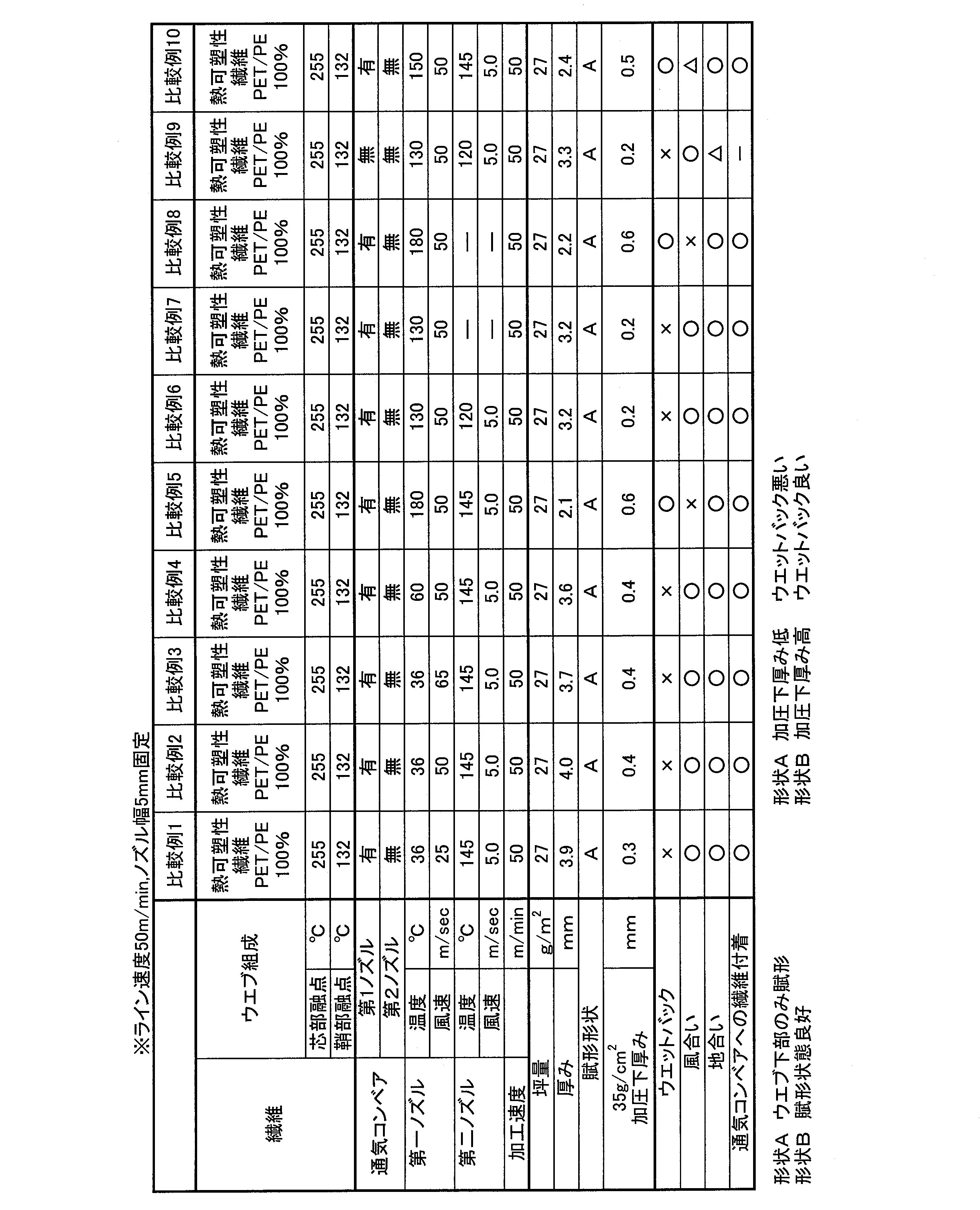
表1および表2に示した結果から明らかなように、各実施例1~13の試験体は、第1の熱風W1の温度がウエブ60の繊維の低融点成分の融点132℃より60℃低い温度である72℃以上、該融点132℃より15℃高い温度である147℃以下であり、第2の熱風W2の温度がウエブ60の繊維の低融点成分の融点132℃以上、ウエブ60の繊維の高融点成分の融点255℃未満で賦形されたものであり、賦形形状が良好であり形状Bの判定となった。また加圧下の厚みが0.6mm以上あり、ウエットバックが良く、さらに、風合いおよび地合いもほぼ良かった。特に、実施例3、実施例6~8および実施例10~13の試験体は、加圧下の厚みが0.7mm以上あり、特にウエットバックが良かった。また実施例5の試験体は特に風合いに優れていた。また実施例1~13(通気コンベアを使用してない実施例12を除く)では、通気コンベア23への繊維付着がほとんどなく、特に、第1ノズル11の吹き出し側から第2ノズル12の吹き出し側にかけて通気コンベア23を連続して配した実施例13では、通気コンベア23への繊維付着が全くなく、連続運転に問題がないことが確認された。
一方、第1の熱風W1の温度が上記温度範囲に入らなかった比較例1~10の試験体は、賦形が不十分であって、賦形形状の判定が形状Aとなった。また、比較例1~10の試験体は比較例5、8、10の試験体を除いてウエットバックが悪かった。また比較例5、8の試験体は、ウエットバックは良いが、風合いが悪かった。さらに第1の熱風W1のみで賦形した比較例7の試験体はウエットバックが悪く、比較例8の試験体は風合いが悪かった。また、比較例1~10(通気コンベアを使用していない比較例9を除く)は、いずれも通気コンベア23への繊維の付着がほとんどなく、連続運転に問題がないことが確認された。
一方、第1の熱風W1の温度が上記温度範囲に入らなかった比較例1~10の試験体は、賦形が不十分であって、賦形形状の判定が形状Aとなった。また、比較例1~10の試験体は比較例5、8、10の試験体を除いてウエットバックが悪かった。また比較例5、8の試験体は、ウエットバックは良いが、風合いが悪かった。さらに第1の熱風W1のみで賦形した比較例7の試験体はウエットバックが悪く、比較例8の試験体は風合いが悪かった。また、比較例1~10(通気コンベアを使用していない比較例9を除く)は、いずれも通気コンベア23への繊維の付着がほとんどなく、連続運転に問題がないことが確認された。
また、賦形形状と加圧下の厚みとはウエットバックに関係していることがわかった。すなわち、形状Aと判定された試験体は、加圧下の厚みが0.4mm以下であるとともに、ウエットバックが悪かった。形状Bと判定された試験体は、加圧下の厚みが0.6mm以上あり、ウエットバックが良かった。したがって、形状Bであり、かつ加圧下の厚みが0.6mm以上であれば、ウエットバックが良いことがわかった。
以上説明したように、所定の温度範囲の第1の熱風W1および第2の熱風W2からなる2度の熱風を吹き付ける賦形によって、賦形形状に優れ、ウエットバックが良く、風合い、地合いがほぼ良い不織布が、通気性コンベアへの繊維付着がほとんどない状態で得られることがわかった。よって、本願発明の不織布の製造方法、不織布および不織布の製造装置では、賦形性のよい低密度で嵩高な不織布が得られる。
次に、図6を参照して、本発明に係る不織布の製造方法の実施に好ましく用いられる不織布の製造装置4について詳細に説明する。
図6に示すように、不織布の製造装置4は、熱可塑性繊維を含有する繊維ウエブ60を搬送する支持体30を有する。上記繊維ウエブ60は支持体30の表面に供給され、支持体30の表面に載った状態でエアースルー方式により賦形処理と毛羽立ちを低減する処理が行われ、所定の方向に送り出される。
上記支持体30は、コンベアで構成され、コンベアベルト30Bが上側両端と下側両端の4か所に配された回転支持ローラ30R(30Ra、30Rb、30Rc、30Rd)に支持されて回転するように構成されている。この回転支持ローラ30Rは、4か所に限定されず、コンベアベルト30Bが円滑に回転するように配されていればよい。コンベアベルト30Bは、その表面に複数の突起状部30Tで構成される凹凸形状を有し、さらに複数の通気部(図示せず)を有する。例えば、突起状部30Tと通気部とは交互にコンベアベルト30Bの面内縦横に配されている。
突起状部30Tは、先端に向かうにしたがって先細りになる形状を有し、その先端部は丸みが形成されている、例えば紡錘体の一端の形状を成す。その高さは不織布の用途、規格等により変わり、特に制限するものではないが、通常、好ましくは、2mm以上10mm以下に形成され、突起ピッチはMD方向に6mm以上10mm以下であり、CD方向に4mm以上6mm以下である。上記MDは機械方向であり不織布の製造時における繊維ウエブ60の流れ方向である。上記CDは繊維ウエブ60の幅方向であり機械方向と直交する方向である。この突起状部30Tは、その高さが低すぎると繊維ウエブ60に十分な凹凸を賦形することができず、高すぎると熱風を吹き付けたときに突起状部30Tが繊維ウエブ60を突き抜ける可能性がある。よって、突起状部30Tは、上記範囲の高さで適宜設定される。そしてより好ましくは、3mm以上8mm以下の高さに形成され、MD方向に6mm以上10mm以下に配され、CD方向に4mm以上6mm以下に配されている。
また通気部(図示せず)は、支持体30に配された複数の開口部からなり、その開口率が支持体30の表面積に対して好ましくは20%以上45%以下に設定されている。開口率が低すぎると繊維ウエブ60に十分な凹凸形状を賦形することが難しくなり、開口率が高すぎると熱風を吹き付けた際に繊維ウエブ60が支持体30の下に移行して支持体30から剥離しにくくなり、賦形形状の悪化や毛羽が形成されやすくなる可能性がある。よって、上記開口率に設定される。また、上記開口率は、より好ましくは25%以上40%以下であり、特に好ましくは30%以上35%以下である。
支持体30は、コンベアベルト30Bが回転支持ローラ30Rに支持されて回転することにより、突起状部30Tを有する面側で、突起状部30Tで繊維ウエブ60を掛け止めるようにして繊維ウエブ60を搬送する。支持体30の突起状部30Tが配されている上方には、繊維ウエブ60の供給方向にそって順に、第1の熱風W1を吹き付けて第1エアースルー工程を行う第1ノズル31と、第2の熱風W2を吹き付けて第2エアースルー工程を行う第2ノズル32と、第3の熱風W3を吹き付けて第3エアースルー工程を行う第3ノズル33とが配され、第2ノズル32と第3ノズル33との間には繊維ウエブ60を冷却する冷却部34が配されている。上記第1、第2ノズル31、32で前段のエアースルーが行われ、上記第3ノズル33で後段のエアースルーが行われる。
第1ノズル31は、第1ヒータ(図示せず)を備え、第1ヒータで加熱された第1の熱風W1を、通気性を有する通気コンベア23を通して突起状部30Tが配されている支持体30の表面に対して、例えばほぼ垂直に吹き付ける。第1ノズル31の吹き出し孔は、好ましくは、MD方向における長さが1mm以上20mm以下であり、CD方向における長さはウエブ幅以上であり、または賦形加工を行う幅である。吹き出し孔は、一列または多列のスリット形状、一列または多列に丸孔、長孔もしくは角孔が千鳥や並列に配置された形態を有している。より好ましくは2mm以上20mm以下の一列のスリット形状を有している。このように、第1ノズル31の吹き出し孔が配されていることから、第1の熱風W1が繊維ウエブ60の表面の幅方向に均一な風速で吹き付けられる。この第1の熱風W1には、上記第1ヒータによって所定温度に加熱された空気、窒素または水蒸気を用いることができる。好ましくは、乾燥が不要な、もしくはコストが低い空気を用いる。
第1ノズル31から吹き出される第1の熱風W1は、繊維ウエブ60の繊維同士を凹凸形状が保持される状態に融着させる温度に第1ヒータによって制御されている。例えば、繊維ウエブ60の繊維が、芯部がポリエチレンテレフタレート(PET)であり鞘部がポリエチレン(PE)の芯鞘構造の複合繊維である場合、第1の熱風W1の温度は、好ましくは80℃以上155℃以下に制御され、より好ましくは130℃以上135℃以下に制御される。
なお、第1の熱風W1の温度が繊維ウエブ60の繊維の低融点成分の融点より低すぎる場合、繊維の戻りが生じ賦形性が低下する。他方、繊維ウエブ60の繊維の低融点成分の融点より高すぎる場合、繊維同士が一気に融着し、自由度の低下により賦形性が損なわれるようになる。
なお、第1の熱風W1の温度が繊維ウエブ60の繊維の低融点成分の融点より低すぎる場合、繊維の戻りが生じ賦形性が低下する。他方、繊維ウエブ60の繊維の低融点成分の融点より高すぎる場合、繊維同士が一気に融着し、自由度の低下により賦形性が損なわれるようになる。
また第1の熱風W1は、好ましくは20m/sec以上120m/sec以下の風速に制御されている。第1ノズル31から吹き出される第1の熱風W1の風速が遅すぎると十分に支持体に沿わないことおよび繊維の融着が進みすぎることで賦形ができず、賦形性が悪化することがある。一方、風速が速すぎると、繊維ウエブ60の繊維が突起状部30Tにより選り分けられ、十分な賦形ができなくなる。よって、第1の熱風W1の風速は上記の範囲とし、より好ましくは40m/sec以上80m/sec以下とする。
さらに第1の熱風W1の吹き付け時間は、好ましくは0.01秒以上0.5秒以下に制御され、より好ましくは0.04秒以上0.08秒以下に制御される。吹き付け時間が短すぎると繊維ウエブを凹凸形状に十分に賦形ができず、一方、吹き付け時間が長すぎると繊維ウエブ60の繊維が突起状部30Tにより選り分けられ、賦形され過ぎた状態になる。
第2ノズル32は、第2ヒータ(図示せず)で加熱された第2の熱風W2を、突起状部30Tが配されているコンベアベルト30Bの表面に対して、例えばほぼ垂直に吹き付ける。第2ノズル32の吹き出し孔には、幅方向、流れ方向に規則的に開孔しているパンチングメタルを使用することが望ましい。この開孔率は、好ましくは10%以上40%以下とし、より好ましくは20%以上30%以下とする。このように、第2ノズル32の吹き出し孔が形成されていることから、第2の熱風W2が繊維ウエブ60の表面の幅方向に均一な温度で吹き付けられる。この第2の熱風W2には、上記第2ヒータによって加熱された空気、窒素または水蒸気を用いることができる。好ましくは、乾燥が不要な、もしくはコストが低い空気を用いる。
第2ノズル32から吹き出される第2の熱風W2は、第2ヒータ(図示せず)によって、賦形された繊維ウエブ60の凹凸形状を保持した状態で繊維ウエブ60の繊維同士を融着させる温度に制御されている。例えば、繊維ウエブ60の繊維が低融点成分とこの低融点成分より融点の高い高融点成分を有する複合繊維の場合、第2の熱風W1は、その低融点成分の融点以上、繊維ウエブ60の繊維の高融点成分の融点未満の温度に制御されている。例えば、繊維ウエブ60の繊維が上述のような芯部がPETであり鞘部がPEの芯鞘構造の複合繊維である場合、第2の熱風W1は、好ましくは130℃以上155℃以下の温度の熱風に制御され、より好ましくは135℃以上150℃以下に制御されている。
なお、第2の熱風W2の温度が低すぎると繊維同士の融着ができずに繊維ウエブ60を凹凸形状に固定することが困難になる。一方、第2の熱風W2の温度が高すぎると、不織布の風合いが悪くなり、嵩がでにくくなる。
なお、第2の熱風W2の温度が低すぎると繊維同士の融着ができずに繊維ウエブ60を凹凸形状に固定することが困難になる。一方、第2の熱風W2の温度が高すぎると、不織布の風合いが悪くなり、嵩がでにくくなる。
また第2の熱風W2は、好ましくは1m/sec以上10m/sec以下の風速に制御されている。第2の熱風W2の風速が遅すぎると熱量が不足するため、不織布強度が不十分になる。一方、風速が速すぎると、繊維ウエブ60が風圧で厚みが小さい状態になり、そこに熱量が多くかかるため、繊維同士の融着が多くなるため、厚みが薄くなり、風合いが固くなり、液浸透性が不十分になる。よって、第2の熱風W2の風速は上記の範囲とし、より好ましくは、2m/sec以上8m/sec以下とする。
さらに第2の熱風W2の吹き付け時間は、好ましくは0.03秒以上5秒以下に制御され、より好ましくは0.1秒以上1秒以下に制御される。吹き付け時間が短すぎると繊維ウエブの繊維同士の融着が十分にできず凹凸形状を固定することが難しくなる。一方、吹き付け時間が長すぎると繊維ウエブ60の繊維同士が融着され過ぎて、液浸透性が得られにくくなる。
上記冷却部34は、第2エアースルー工程を行う第2ノズル32と第3エアースルー工程を行う第3ノズル33との間に配された空間である。この空間を配することにより、言い換えれば、第2エアースルー工程と第3エアースルー工程とを連続して行わないようにすることにより、第2エアースルー工程後に繊維ウエブ60の繊維の融点よりも低い温度に自然冷却する。または、後述するが、冷却部34は、繊維ウエブ60を強制冷却させる手段を用いることもできる。
第3ノズル33は、第3ヒータ(図示せず)で加熱された第3の熱風W3を、突起状部30Tが配されているコンベアベルト30Bの表面(凹凸形状が配された面)に対して、例えばほぼ垂直に吹き付ける。第3ノズル33の吹き出し孔は、好ましくは幅が例えば200mm以上10mm以下で、繊維ウエブ60の幅方向にウェブ幅以上の長さに、一列または多列に丸孔、長孔もしくは角孔が千鳥や並列に並んだ形態を有している。このように、第3ノズル33の吹き出し孔が配されていることから、第3の熱風W3が繊維ウエブ60の表面の幅方向に均一な温度で吹き付けられる。この吹き出し孔は、支持体30のコンベアベルト30Bの回転方向に複数個所に配置することができる。また、この第3の熱風W3には、上記第3ヒータによって加熱された空気、窒素または水蒸気を用いることができる。好ましくは、乾燥が不要な、もしくはコストが低い空気を用いる。
第3ノズル33から吹き出される第3の熱風W3は、第3ヒータ(図示せず)によって、冷却された繊維ウエブ60の凹凸形状を保持した状態で繊維ウエブ60の毛羽立ち繊維と他の繊維同士を融着させる温度に制御されている。例えば、繊維ウエブ60の繊維が上述のような芯部がPETであり鞘部がPEの芯鞘構造の複合繊維である場合、第3の熱風W3は、130℃以上155℃以下の温度の熱風に制御されている。好ましくは130℃以上145℃以下に制御されている。
なお、第3の熱風W3の温度が低すぎると繊維同士の融着ができずに毛羽立ちを低減することが困難になる。一方、第3の熱風W3の温度が高すぎると、毛羽立ち繊維以外の繊維同士も融着されて、液浸透性が得られ難くなる。
なお、第3の熱風W3の温度が低すぎると繊維同士の融着ができずに毛羽立ちを低減することが困難になる。一方、第3の熱風W3の温度が高すぎると、毛羽立ち繊維以外の繊維同士も融着されて、液浸透性が得られ難くなる。
また第3の熱風W3は、好ましくは0.5m/sec以上5m/sec以下の風速に制御される。第3の熱風W3の風速が遅すぎると毛羽立ち繊維を寝せることができず、毛羽立ちの低減が不十分になる。一方、風速が速すぎると、風圧で不織布の厚みが小さい状態になり、その状態で加熱されるため毛羽立ち繊維以外の繊維同士の融着が多く起こるため、厚みが小さくなり、感触と液浸透性が不十分になる。よって、第3の熱風W3の風速は上記の範囲とし、より好ましくは、2m/sec以上8m/sec以下とする。
さらに第3の熱風W3の吹き付け時間は、好ましくは0.3秒以上10秒以下に制御され、より好ましくは2秒以上6秒以下に制御される。吹き付け時間が短すぎると毛羽立ち繊維と他の繊維同士の融着が十分にできず毛羽立ちを低減することが難しくなる。一方、吹き付け時間が長すぎると繊維ウエブ60の毛羽立ち繊維以外の繊維同士が融着され過ぎて、厚みが小さくなり、風合いと液透過性が得られ難くなる。
上記第1ノズル31の吹き出し方向には、第1ノズル31から吹き出され、繊維ウエブ60、支持体30を通ってきた第1の熱風W1を排気する吸引部35が配されている。この吸引部35には、吸引された第1の熱風W1を排出する排気装置(図示せず)が接続されていてもよい。またさらに、第2ノズル32の吹き出し方向には、第2ノズル32から吹き出され、繊維ウエブ60、支持体30を通ってきた第2の熱風W2を排気する吸引部36が配されている。この吸引部36には、吸引された第2の熱風W2を排出する排気装置(図示せず)が接続されていてもよい。さらにまた、第3ノズル33の吹き出し方向には、第3ノズル33から吹き出され、繊維ウエブ60、支持体30を通ってきた第3の熱風W3を排気する吸引部37が配されている。この吸引部37には、吸引された第3の熱風W3を排出する排気装置(図示せず)が接続されていてもよい。また、それぞれの排気装置は一つの排気装置として、それぞれの吸引部35、36、37に接続されたものでもよい。
上述の第4実施形態の不織布の製造装置4では、賦形された繊維ウエブ60を冷却する冷却部34を配したことによって、繊維同士が融着された交点を強固にして繊維同士によるネットワーク構造を強固に固定できるので、繊維ウエブ60に賦形された凹凸形状を固定できる。その冷却された状態の毛羽立ち繊維に第3の熱風W3を吹き付ける第3ノズル33を備えたことから、第3ノズル33から吹き出された第3の熱風W3により毛羽立ち繊維を軟化させ、その毛羽立ちしている部分を寝せることができ、寝せた状態の毛羽立ち繊維の毛羽立ちしていた部分と他の繊維(ネットワーク構造の繊維)の毛羽立ちしていない部分同士が融着して固定できる。これによって、毛羽立ちを低減できるので、賦形不織布(繊維ウエブ60)表面に外力が加わっても毛羽立ちにくくなり、滑らかな感触の肌触りが良い柔らかな不織布が得られる。また毛羽立ち繊維を融着する際に、賦形形状がしっかりと固定されているため、他の繊維に過度の融着が起こらないので、厚みや空隙が確保され、液透過性に優れた賦形不織布を提供できる。
また、第1ノズル31から吹き出された第1の熱風W1により繊維ウエブ60の繊維同士を凹凸形状が保持される状態にできる。このため、支持体30の突起状部30T間にもぐりこんだ繊維ウエブ60の繊維が戻りにくくなる。この状態で、第2ノズル32から吹き出された第2の熱風W2により、繊維ウエブ60の繊維同士が融着され、凹凸形状を維持した状態で固定することができる。このように、繊維ウエブ60に第1、第2の熱風W1、W2を吹き付けることから、熱により繊維ウエブ60の繊維が柔軟化されて、支持体30の突起状部30Tの表面形状に沿いやすくなり、凹凸形状の保持性がよくなる。その際、第1、第2の熱風W1、W2は、支持体30に配された通気孔を通過することから、繊維ウエブ60を突起状部30Tの表面により沿わせ易くなる。その結果、賦形性のよい低密度で嵩高な賦形不織布が得られる。
次に、上述の冷却部34の別の態様について図7を参照して以下に説明する。
図7に示すように、上記第4実施形態の不織布の製造装置4において、上記冷却部34として、第2ノズル32と第3ノズル33との間の繊維ウエブ60に冷却気体Wcを吹き付ける冷却ノズル34Nを配する。冷却気体Wcの温度は、繊維ウエブ60の熱可塑性繊維の融点よりも低い温度、好ましくは繊維ウエブ60を構成する繊維の低融点成分の融点よりも低い温度とする。より好ましくは100℃以下に、さらに好ましくは50℃以下にする。冷却気体Wcには、例えば、空気、窒素ガス、水蒸気等を用いることができる。好ましくは乾燥が不要な、もしくはコストが低い空気を用いる。なお冷却気体Wcは、温度が高すぎると十分な冷却効果が得られない。
図7に示すように、上記第4実施形態の不織布の製造装置4において、上記冷却部34として、第2ノズル32と第3ノズル33との間の繊維ウエブ60に冷却気体Wcを吹き付ける冷却ノズル34Nを配する。冷却気体Wcの温度は、繊維ウエブ60の熱可塑性繊維の融点よりも低い温度、好ましくは繊維ウエブ60を構成する繊維の低融点成分の融点よりも低い温度とする。より好ましくは100℃以下に、さらに好ましくは50℃以下にする。冷却気体Wcには、例えば、空気、窒素ガス、水蒸気等を用いることができる。好ましくは乾燥が不要な、もしくはコストが低い空気を用いる。なお冷却気体Wcは、温度が高すぎると十分な冷却効果が得られない。
また、上記冷却ノズル34Nを配した不織布の製造装置5は、上記冷却ノズル34N以外の構成である支持体30、突起状部30T、通気部(図示せず)、第1ノズル31、第2ノズル32、第3ノズル33、吸引部35、吸引部36、吸引部37等は、前記不織布の製造装置4と同様の構成を有する。
上記不織布の製造装置5では、第2の熱風W2を吹き付ける第2エアースルー工程直後の繊維ウエブ60は、冷却ノズル34Nから吹き出された冷却気体Wcが吹き付けられて強制的に冷却される。よって、第2の熱風W2により融着された繊維同士の交点をより強固に固定でき、繊維ウエブ60を賦形された凹凸形状にしっかり固定できる。それとともに、前述の不織布の製造装置4と同様に毛羽立ちを抑えることができ、凹凸形状に賦形された肌触り感が良い柔らかな賦形不織布が得られる。
次に、上述の冷却部34のさらに別の態様について図8を参照して以下に説明する。
図8に示すように、前述の第4実施形態の不織布の製造装置4において、上記冷却部34として、第2ノズル32と第3ノズル33との間の繊維ウエブ60を支持体30のコンベアベルト30Bの表面から上方に引き離す冷却部ローラ34Rを配する。この冷却部ローラ34Rは、回転自在で、表面が滑らかなローラで構成されている。または、上記冷却部ローラ34Rの代わりに、表面が滑らかな丸棒、もしくは繊維ウエブ60が摺動する面が滑らかな曲面である棒状体で構成されてもよい。さらに、上記冷却部ローラ34Rの内部に冷却媒体として例えば冷却気体もしくは冷却液体を流せる流路を配してもよい。この流路に冷却媒体を流すことにより、冷却部ローラ34Rによる繊維ウエブ60の冷却効率がさらに高められる。もちろん、上記流路は、上記丸棒や棒状体の内部に配することもできる。
図8に示すように、前述の第4実施形態の不織布の製造装置4において、上記冷却部34として、第2ノズル32と第3ノズル33との間の繊維ウエブ60を支持体30のコンベアベルト30Bの表面から上方に引き離す冷却部ローラ34Rを配する。この冷却部ローラ34Rは、回転自在で、表面が滑らかなローラで構成されている。または、上記冷却部ローラ34Rの代わりに、表面が滑らかな丸棒、もしくは繊維ウエブ60が摺動する面が滑らかな曲面である棒状体で構成されてもよい。さらに、上記冷却部ローラ34Rの内部に冷却媒体として例えば冷却気体もしくは冷却液体を流せる流路を配してもよい。この流路に冷却媒体を流すことにより、冷却部ローラ34Rによる繊維ウエブ60の冷却効率がさらに高められる。もちろん、上記流路は、上記丸棒や棒状体の内部に配することもできる。
また、上記冷却部ローラ34Rを配した不織布の製造装置6は、上記冷却部ローラ34R以外の構成である支持体30、突起状部30T、通気部(図示せず)、第1ノズル31、第2ノズル32、第3ノズル33、吸引部35、吸引部36、吸引部37等は、前記不織布の製造装置4と同様の構成を有する。
上記不織布の製造装置6では、第2の熱風W2を吹き付ける第2エアースルー工程直後の繊維ウエブ60は、冷却部ローラ34Rによって、コンベアベルト30Bの表面から一旦引き離されるので効率良く冷却される。よって、第2の熱風W2により融着された繊維同士の交点をより強固に固定でき、繊維ウエブ60を賦形された凹凸形状にしっかり固定できる。それとともに、前述の不織布の製造装置4と同様に毛羽立ちを抑えることができ、凹凸形状に賦形された肌触り感が良い柔らかな賦形不織布が得られる。
次に、本発明に係る不織布の製造方法の実施に用いるのに好適な第5実施形態の不織布の製造装置について、図9を参照しながら、以下に説明する。
図9に示すように、第5実施形態の不織布の製造装置7は、前述の不織布の製造装置4において、支持体(第1支持体)30とは別の支持体(第2支持体)38を設け、第3の熱風W3を吹き付ける第3エアースルー工程を第2支持体30で行うようにしたものである。
図9に示すように、第5実施形態の不織布の製造装置7は、前述の不織布の製造装置4において、支持体(第1支持体)30とは別の支持体(第2支持体)38を設け、第3の熱風W3を吹き付ける第3エアースルー工程を第2支持体30で行うようにしたものである。
具体的には、上記第2支持体38は、上側に繊維ウエブ60を載せて搬送するコンベアで構成され、コンベアベルト38Bが上側両端と下側両端の4か所に配された回転支持ローラ38R(38Ra、38Rb、38Rc、38Rd)に支持されて回転するように、かつ繊維ウエブ60が載せられて搬送される部分は平面になるように構成されている。回転支持ローラ38Rは、4か所に限定されず、コンベアベルト38Bが円滑に回転するように、かつ平面部分が形成されるように配されていればよい。またコンベアベルト38Bは、通気性を有するメッシュベルトで構成されることが好ましく、例えば、12メッシュから60メッシュのメッシュベルトで構成されることがより好ましい。
第2支持体38は、コンベアベルト38B上に、第1支持体30上で第1、第2エアースルー工程を行った繊維ウエブ60が送給されるように、第1支持体30と離間して直列に配されている。したがって、第1支持体30と第2支持体38との間が冷却部34になる。この冷却部34の構成は前述の図6から図8を参照して説明した自然冷却または強制冷却の冷却部34と同様の構成を採用することができる。
第2支持体38は、コンベアベルト38B上に、第1支持体30上で第1、第2エアースルー工程を行った繊維ウエブ60が送給されるように、第1支持体30と離間して直列に配されている。したがって、第1支持体30と第2支持体38との間が冷却部34になる。この冷却部34の構成は前述の図6から図8を参照して説明した自然冷却または強制冷却の冷却部34と同様の構成を採用することができる。
上記第2支持体38の上方には、前述したのと同様な第3ノズル33が配されている。また、第3ノズル33の吹き出し方向には、第3ノズル33から吹き出され、繊維ウエブ60、第2支持体38を通ってきた第3の熱風W3を排気する吸引部37が配されている。この吸引部37には、吸引された第3の熱風W3を排出する排気装置(図示せず)が接続されていてもよい。
また、不織布の製造装置7は、上記第2支持体38以外の構成である第1支持体30、突起状部30T、通気部(図示せず)、第1ノズル31、第2ノズル32、第3ノズル33、吸引部35、吸引部36、吸引部37等は、前述の不織布の製造装置4と同様の構成を有する。
上述の第5実施形態の不織布の製造装置7は、前述の不織布の製造装置4と同様な作用効果を奏するとともに、第2の熱風W2を吹き付ける第2エアースルー工程後に第1支持体30から繊維ウエブ60を剥離することから、繊維ウエブ60を自然冷却できる。これによって、第2エアースルー工程で融着させた繊維同士が強固に固定でき、繊維ウエブ60に賦形された凹凸形状がしっかりと固定できる。
また、繊維ウエブ60を第1支持体30から剥離してから第2支持体38に載置することから、第2支持体38を冷却しておくことで第2支持体38に繊維ウエブ60が載ったときにも繊維ウエブ60を冷却できる。これにより、繊維ウエブ60の凹凸形状の保持性がさらに高められるので、第3の熱風W3の温度を許容範囲内で高めて、毛羽立ち繊維を他の繊維に確実に融着させて、毛羽立ちをより低減することができる。
また、繊維ウエブ60を第1支持体30から剥離してから第2支持体38に載置することから、第2支持体38を冷却しておくことで第2支持体38に繊維ウエブ60が載ったときにも繊維ウエブ60を冷却できる。これにより、繊維ウエブ60の凹凸形状の保持性がさらに高められるので、第3の熱風W3の温度を許容範囲内で高めて、毛羽立ち繊維を他の繊維に確実に融着させて、毛羽立ちをより低減することができる。
さらに、第2支持体38に通気性を有するコンベアベルト38Bとして、メッシュベルトを用いることで、繊維ウエブ60の両面の毛羽立ちを無くすことができる。これは、メッシュベルトのような通気性を有する支持体を用いることで、繊維ウエブ60の表面側の毛羽立ちは、上述したように、第3の熱風W3により毛羽立ち繊維を軟化させ、その毛羽立ちしている部分を寝せてから、毛羽立ち繊維の毛羽立ちしていた部分と他の繊維の毛羽立ちしていない部分同士を融着させることで、毛羽立ちが低減できる。また、通気性を有する支持体を用いていることから、第3の熱風W3が繊維ウエブ60を通ってコンベアベルト38Bの裏面側に吹き抜けやすくなり、ウエブの自重とウエブにかかる風圧で裏面側の毛羽立ち繊維が寝かされた状態になり、他の繊維と融着される。
また、メッシュベルトとして12メッシュから60メッシュのベルトを用いることにより、12メッシュ以上では目開きの面積(目開きの縦寸法×横寸法)が1.5mm2以下になり、毛羽立ち繊維が寝かされて融着されるため毛羽立ちが低減するという効果が得られる。メッシュが60メッシュより大きくなると局部抵抗が増加により熱風の風速を出すためのコストが増加する。
また、メッシュベルトとして12メッシュから60メッシュのベルトを用いることにより、12メッシュ以上では目開きの面積(目開きの縦寸法×横寸法)が1.5mm2以下になり、毛羽立ち繊維が寝かされて融着されるため毛羽立ちが低減するという効果が得られる。メッシュが60メッシュより大きくなると局部抵抗が増加により熱風の風速を出すためのコストが増加する。
次に、本発明に係る不織布の製造方法の実施に用いるのに好適な第6実施形態の不織布の製造装置について、図10を参照しながら、以下に説明する。
図10に示すように、不織布の製造装置8は、前述の不織布の製造装置7において、別の支持体(第2支持体)38を送給されてくる繊維ウエブ60の表面側に配し、前述の第3エアースルー工程を第2支持体38で行うようにしたものである。
具体的には、第2支持体38は、前述した第2実施形態の第2支持体38の上下を逆転させた以外、構成は同様のものである。
第2支持体38は、コンベアベルト38Bの下に第1支持体30上で第1、第2の熱風W1、W2を吹き付けて賦形処理を行った繊維ウエブ60が送給されるように、かつ第1支持体30と第2支持体38とが離間して配置されている。第1支持体30と第2支持体38との間が冷却部34になる。この冷却部34の構成は前述の図6ないし図8を参照して説明した自然冷却または強制冷却の冷却部34と同様の構成を採用することができる。
図10に示すように、不織布の製造装置8は、前述の不織布の製造装置7において、別の支持体(第2支持体)38を送給されてくる繊維ウエブ60の表面側に配し、前述の第3エアースルー工程を第2支持体38で行うようにしたものである。
具体的には、第2支持体38は、前述した第2実施形態の第2支持体38の上下を逆転させた以外、構成は同様のものである。
第2支持体38は、コンベアベルト38Bの下に第1支持体30上で第1、第2の熱風W1、W2を吹き付けて賦形処理を行った繊維ウエブ60が送給されるように、かつ第1支持体30と第2支持体38とが離間して配置されている。第1支持体30と第2支持体38との間が冷却部34になる。この冷却部34の構成は前述の図6ないし図8を参照して説明した自然冷却または強制冷却の冷却部34と同様の構成を採用することができる。
上記第2支持体38の下方には、前述したのと同様な第3ノズル33が配されている。また、第3ノズル33の吹き出し方向には、第3ノズル33から吹き出され、繊維ウエブ60、第2支持体38を通ってきた第3の熱風W3を排気する吸引部37が配されている。この吸引部37には、吸引された第3の熱風W3を排出する排気装置(図示せず)が接続されていてもよい。
また、不織布の製造装置8は、上記第2支持体38、第3ノズル33、吸引部37の配置が異なる以外、第1支持体30、突起状部30T、通気部(図示せず)、第1ノズル31、第2ノズル32、吸引部35、吸引部36等は、前記不織布の製造装置7と同様の構成を有する。
上述の第6実施形態の不織布の製造装置8は、前述の不織布の製造装置6と同様に、凹凸形状に賦形された肌触り感が良い柔らかな賦形不織布を得ることができる。特に繊維ウエブ60の裏面側の毛羽立ちがより低減できる。
なお、好ましい実施形態としてコンベアで構成された不織布の製造装置を例に説明したが、本願の好ましい製造装置は、コンベア式に限定されず、ドラム式であってもよい。
なお、好ましい実施形態としてコンベアで構成された不織布の製造装置を例に説明したが、本願の好ましい製造装置は、コンベア式に限定されず、ドラム式であってもよい。
次に、本発明に係る不織布の製造方法の第4実施形態について、前述の図6および図11を参照しながら、以下に説明する。
前述の図6に示すように、第4実施形態の不織布の製造方法は、前述の不織布の製造装置4によって実現される。
前述の図6に示すように、第4実施形態の不織布の製造方法は、前述の不織布の製造装置4によって実現される。
まず、繊維ウエブ60を支持体30の突起状部30Tが配された上面側に供給する。
繊維ウエブ60の繊維に用いることができる繊維材料は特に限定されない。具体的には、前記したのと同様のものを用いることができる。
繊維ウエブ60の繊維に用いることができる繊維材料は特に限定されない。具体的には、前記したのと同様のものを用いることができる。
そして、上記繊維ウエブ60に熱風を吹き付けて通気性の支持体30に追随させる前段のエアースルー工程として、支持体30表面に送給された繊維ウエブ60に第1ノズル31より第1の熱風W1を吹き付ける第1エアースルー工程を行う。このとき、第1の熱風W1は、繊維ウエブ60が載っている支持体30の表面に対して垂直方向から吹き付ける。また第1ノズル31の吹き出し数は繊維ウエブ60の送給方向にそって複数個所としてもよい。この第1の熱風W1によって、支持体30の突起状部30Tの形状に沿った凹凸形状に繊維ウエブ60が賦形される。繊維ウエブ60の繊維同士の融着は、その凹凸形状が維持できる程度でよい。このとき、第1の熱風W1の温度は、繊維の種類、加工速度、熱風の風速などによって変わるので一義的に定まるものではないが、繊維ウエブ60の繊維が、芯部がポリエチレンテレフタレート(PET)であり鞘部がポリエチレン(PE)の芯鞘構造の複合繊維である場合、好ましくは80℃以上155℃以下とし、より好ましくは130℃以上135℃以下とする。
なお、第1の熱風W1の温度が低すぎる場合、繊維の戻りが生じ賦形性が低下する。一方、温度が高すぎる場合、繊維同士が一気に融着し、自由度の低下により賦形性が損なわれることとなる。
なお、第1の熱風W1の温度が低すぎる場合、繊維の戻りが生じ賦形性が低下する。一方、温度が高すぎる場合、繊維同士が一気に融着し、自由度の低下により賦形性が損なわれることとなる。
また第1の熱風W1は、好ましくは20m/sec以上120m/sec以下の風速とする。第1の熱風W1の風速が遅すぎると十分な賦形ができず、賦形性が損なわれることがある。一方、風速が速すぎると、繊維ウエブ60の繊維が突起状部30Tにより選り分けられ、賦形され過ぎた状態になる。よって、第1の熱風W1の風速は上記の範囲とし、より好ましくは、40m/sec以上80m/sec以下とする。
さらに第1の熱風W1の吹き付け時間は、好ましくは0.01秒以上0.5秒以下とし、より好ましくは、0.04秒以上0.08秒以下とする。吹き付け時間が短すぎると繊維ウエブ60の繊維同士の融着が不十分になり凹凸形状に十分に賦形ができなくなる。一方、吹き付け時間が長すぎると繊維ウエブ60の繊維同士の融着が進み過ぎ、自由度の低下により賦形性が損なわれることとなる。
そして繊維ウエブ60を通過した第1の熱風W1は、支持体30の通気部を通って吸引部35から外部に排出される。
そして繊維ウエブ60を通過した第1の熱風W1は、支持体30の通気部を通って吸引部35から外部に排出される。
次に、繊維ウエブ60を支持体30のコンベアベルト30Bの回転とともに第2ノズル32の第2の熱風W2の吹き付け位置まで搬送する。さらに前段のエアースルー工程として、第2ノズル32によって第2の熱風W2を繊維ウエブ60に吹き付け、繊維ウエブ60の凹凸形状を維持した状態で繊維同士を融着させて凹凸形状を固定する第2エアースルー工程を行う。このとき、第2の熱風W2は、繊維ウエブ60の表面に対して垂直方向から吹き付ける。また第2ノズル32の吹き出し数は繊維ウエブ60の送給方向にそって複数個所とすることが好ましい。
第2の熱風W2の温度は、繊維の種類、加工速度、熱風の風速などによって変わるので一義的に定まるものではないが、繊維ウエブ60の繊維が上述のようなPETとPEとの芯鞘構造の複合繊維である場合、繊維ウエブ60の繊維の低融点成分の融点以上、繊維ウエブ60の繊維の高融点成分の融点未満とする。好ましくは135℃以上155℃以下とし、より好ましい温度として135℃以上150℃以下とする。
なお、第2の熱風W2の温度が繊維ウエブ60の繊維の低融点成分の融点より低くなると、凹凸形状の保持性が低下し、繊維ウエブ60の繊維の高融点成分の融点以上になると、風合いが悪くなり、また嵩がでにくくなる。
第2の熱風W2の温度は、繊維の種類、加工速度、熱風の風速などによって変わるので一義的に定まるものではないが、繊維ウエブ60の繊維が上述のようなPETとPEとの芯鞘構造の複合繊維である場合、繊維ウエブ60の繊維の低融点成分の融点以上、繊維ウエブ60の繊維の高融点成分の融点未満とする。好ましくは135℃以上155℃以下とし、より好ましい温度として135℃以上150℃以下とする。
なお、第2の熱風W2の温度が繊維ウエブ60の繊維の低融点成分の融点より低くなると、凹凸形状の保持性が低下し、繊維ウエブ60の繊維の高融点成分の融点以上になると、風合いが悪くなり、また嵩がでにくくなる。
また第2の熱風W2は、好ましくは第1の熱風W1の風速よりも遅く設定し、好ましくは1m/sec以上10m/sec以下とする。第2の熱風W2の風速が遅すぎると熱量が不足するため、不織布強度が不十分になる。一方、風速が速すぎると繊維ウエブ60が風圧で厚みが小さくなり、その状態で加熱されると繊維同士の融着が多くなるため、感触は硬くなり、厚みが薄くなり液浸透性が不十分になる。よって、第2の熱風W2の風速は上記の範囲とし、より好ましくは、2m/sec以上8m/sec以下とする。
さらに第2の熱風W2の吹き付け時間は、好ましくは0.03秒以上5秒以下とし、より好ましくは、0.1秒以上1秒以下とする。吹き付け時間が短すぎると繊維ウエブ60の繊維同士の融着が十分にできず凹凸形状を固定することが難しくなる。一方、吹き付け時間が長すぎると繊維ウエブ60の繊維同士が融着され過ぎて、液浸透性が得られ難くなる。
上述の第1、第2エアースルー工程で第1、第2の熱風W1,W2を吹き付けて賦形した繊維ウエブ60は、図11(1)に示すように、嵩高のある状態に繊維ウエブ60の繊維同士が融着されている。しかし、表面は毛羽立ちを生じている。
次に、上記第1、第2エアースルー工程で賦形された繊維ウエブ60を冷却する。この冷却は、自然冷却または強制冷却で行うことができる。その冷却温度は、繊維ウエブ60の熱可塑性繊維の融点よりも低い温度、好ましくは繊維ウエブ60を構成する繊維の低融点成分の融点よりも低い温度とする。好ましくは100℃以下にする。
この冷却によって、繊維ウエブ60の繊維同士の融着点が強固に固化される(図11(2)参照。)。
この冷却によって、繊維ウエブ60の繊維同士の融着点が強固に固化される(図11(2)参照。)。
そして賦形された繊維ウエブ60を支持体30のコンベアベルト30Bの回転とともに第3ノズル33の第3の熱風W3の吹き付け位置に搬送する。その間に、繊維ウエブ60は、冷却部34を通ることによって、繊維ウエブ60の熱可塑性繊維の融点より低い温度に冷却される。この冷却は、自然冷却であっても、前述の図7、図8によって説明した強制冷却であってもよい。好ましくは強制冷却により100℃以下に冷却する。繊維ウエブ60を冷却することによって、第2の熱風W2の吹き付けによる繊維同士が融着した交点部分の固化が確実になされる(融着ネットワーク構造が構成される)ようになる。特に繊維ウエブ60を100℃以下に冷却することにより、繊維同士の融着の交点部分をより強固に固定することができ、繊維ウエブ60の基部(繊維ウエブ60の毛羽立ち繊維を除く融着固定化された繊維部分)の厚みを維持できるようになる。鞘樹脂がPEの場合、融点は125℃~135℃であるが軟化点温度は100℃~130℃であるため、100℃以下に冷却することで固化がいっそう確実になる。
第3の熱風W3の吹き付け位置まで搬送された繊維ウエブ60に対して、第3ノズル33によって第3の熱風W3を吹き付け、繊維ウエブ60の凹凸形状を保持した状態で繊維ウエブ60の毛羽立ち繊維と他の繊維同士を融着させる第3エアースルー工程を行う。このときの第3の熱風W3の温度は、繊維の種類、加工速度、熱風の風速などによって変わるので一義的に定まるものではないが、繊維ウエブ60の繊維が、上述のようなPETとPEとの芯鞘構造の複合繊維である場合、好ましくは130℃以上155℃以下とし、より好ましくは130℃以上145℃以下とする。
なお、第3の熱風W3の温度が低すぎると毛羽立ち繊維と他の繊維同士の融着ができずに毛羽立ちを低減することが困難になる。一方、第3の熱風W3の温度が高すぎると、毛羽立ち繊維以外の繊維同士も融着されて、液浸透性が得られ難くなる。
なお、第3の熱風W3の温度が低すぎると毛羽立ち繊維と他の繊維同士の融着ができずに毛羽立ちを低減することが困難になる。一方、第3の熱風W3の温度が高すぎると、毛羽立ち繊維以外の繊維同士も融着されて、液浸透性が得られ難くなる。
また第3の熱風W3は、前記の第1の熱風W1の風速よりも遅い風速で、かつ繊維ウエブ60の毛羽立ち繊維を寝させる風速とする。具体的には、好ましくは1.0m/sec以上5m/sec以下とする。第3の熱風W3の風速が遅すぎると毛羽立ち繊維を寝せることができず、毛羽立ちの低減が不十分になる。一方、風速が速すぎると、風圧で不織布の厚みが小さい状態になり、その状態で加熱されるため毛羽立ち繊維以外の繊維同士の融着が多く起こるため、厚みが小さくなり、感触と液浸透性が不十分になる。よって、第3の熱風W3の風速は上記の範囲とし、より好ましくは、1m/sec以上2m/sec以下とする。さらに、上記風速の範囲内で速い風速を選択することにより、寝せた毛羽立ち繊維を繊維ウエブ60の基部内に入り込ませることができるのでより好ましい。
さらに第3の熱風W3の吹き付け時間は、好ましくは0.3秒以上10秒以下とし、より好ましくは、2秒以上6秒以下とする。吹き付け時間が短すぎると毛羽立ち繊維と他の繊維同士の融着が十分にできず毛羽立ちを低減することが難しくなる。一方、吹き付け時間が長すぎると繊維ウエブ60の毛羽立ち繊維以外の繊維同士が融着され過ぎて、液透過性が得られ難くなる。
この第3エアースルー工程では、図11の(3)に示すように、第3の熱風W3の熱により毛羽立ち繊維が軟化され、その毛羽立ちしている部分が風圧によって寝せられて、毛羽立ち繊維の毛羽立ちしていた部分と他の繊維(基部の繊維)の毛羽立ちしていない部分同士が新たな融着点で融着する。そして第3エアースルー工程後、図11の(4)に示すように、毛羽立ち繊維と他の繊維同士の融着点が固化され、毛羽立ちがない賦形不織布が製造される。このとき、賦形不織布の基部がしっかり固定されているので、第3エアースルー工程で繊維ウエブ60の厚みが薄くなることはなく、十分な厚みが得られる。さらに図11の(5)に示すように、賦形不織布の表面に外力をかけて使用状態を再現しても、毛羽立ち繊維が起き上がって毛羽立つことはなかった。
なお、この製造方法では、第3の熱風W3の吹き付けによって毛羽立ち繊維を軟化させて変形させているが、第2の熱風W2の吹き付けによって毛羽立ち繊維を軟化させて寝せるように変形させてもよい。
上述の第4実施形態の不織布の製造方法では、賦形された繊維ウエブ60は繊維同士が融着された交点が冷却されることによって繊維のネットワークがしっかり固定され、繊維ウエブ60に賦形された凹凸形状が固定された状態になる。その固定された状態で毛羽立ち繊維に第3の熱風W3を吹き付けることから、毛羽立ち繊維を軟化させ寝せることができる。このとき、繊維ウエブ60の基部の繊維同士がしっかり固定されているので、第3の熱風W3を吹き付けても基部の厚みは薄くならず、毛羽立ち部分だけ寝せることができる。その寝せた状態の毛羽立ち繊維と他の繊維同士が融着するため、毛羽立ち繊維は寝た状態で、例えばループ状に他の繊維と融着して固定される。これにより、毛羽立ちが低減され、また寝せた毛羽立ち繊維が元の毛羽立ち状態に戻ることも低減されるので、凹凸形状に賦形された滑らかな感触の肌触り感が良い柔らかな賦形不織布を得ることができる。しかも繊維ウエブ60の基部が薄くならないので低密度で嵩高い賦形不織布になる。
このような賦形不織布を吸収性物品に用いることで、見た目の印象が良く、肌触りが良い吸収性物品を得ることができる。
このような賦形不織布を吸収性物品に用いることで、見た目の印象が良く、肌触りが良い吸収性物品を得ることができる。
次に、本発明に係る不織布の製造方法の第5実施形態について、前述の図9を参照しながら、以下に説明する。
前述の図9に示すように、第5実施形態の不織布の製造方法は、前述の不織布の製造装置7によって実現される。
第1支持体30表面に繊維ウエブ60を送給し、前述の第4実施形態の製造方法と同様にして、第1エアースルー工程と第2エアースルー工程とを順に行う。
第2エアースルー工程後、第1支持体30から繊維ウエブ60を剥離して別の支持体としての第2支持体38に供給することで、繊維ウエブ60を冷却する。この冷却は、自然冷却であっても、強制冷却であってもよいが、好ましくは前述の冷却ノズル34Nや冷却部ローラ34Rを用いた強制冷却とする。この冷却により、繊維ウエブ60の凹凸形状の保持性がさらに高められるので、第3の熱風W3の温度を許容範囲内で高めて、毛羽立ち繊維を他の繊維に確実に融着させて、毛羽立ちをより低減することができる。
前述の図9に示すように、第5実施形態の不織布の製造方法は、前述の不織布の製造装置7によって実現される。
第1支持体30表面に繊維ウエブ60を送給し、前述の第4実施形態の製造方法と同様にして、第1エアースルー工程と第2エアースルー工程とを順に行う。
第2エアースルー工程後、第1支持体30から繊維ウエブ60を剥離して別の支持体としての第2支持体38に供給することで、繊維ウエブ60を冷却する。この冷却は、自然冷却であっても、強制冷却であってもよいが、好ましくは前述の冷却ノズル34Nや冷却部ローラ34Rを用いた強制冷却とする。この冷却により、繊維ウエブ60の凹凸形状の保持性がさらに高められるので、第3の熱風W3の温度を許容範囲内で高めて、毛羽立ち繊維を他の繊維に確実に融着させて、毛羽立ちをより低減することができる。
冷却後、第2支持体38のコンベアベルト38B上に繊維ウエブ60を供給し、その繊維ウエブ60に第3ノズル33から吹き出された第3の熱風W3を吹き付け、繊維ウエブ60の凹凸形状を維持した状態で毛羽立ち繊維と他の繊維同士を融着させる第3エアースルー工程を行う。第3の熱風W3の温度、風速、吹き付け時間等の条件は、前述の第4実施形態の製造方法で説明したのと同様である。
上述の第5実施形態の不織布の製造方法は、前述の第4実施形態の不織布の製造方法と同様な作用効果を奏するとともに、繊維ウエブ60の両面の毛羽立ちを低減することができる。これは、繊維ウエブ60の表面側では前述した作用により、毛羽立ち繊維を軟化させ寝せてから、毛羽立ち繊維とその他の繊維同士を融着させ固定することができる。一方、繊維ウエブ60の裏面側では、第3の熱風W3が繊維ウエブ60を通ってコンベアベルト38Bの裏面側に吹き抜けやすくなっていることから、毛羽立ち繊維は、ウエブの自重とウエブにかかる風圧で裏面側の毛羽立ち繊維が寝かされた状態になり、他の繊維と融着されるとなるので、毛羽立ち繊維とその他の繊維同士を融着させ固定することができる。
これにより、繊維ウエブ60の両面の毛羽立ちを低減することができ、また寝せた毛羽立ち繊維が元の毛羽立ち状態に戻ることも低減されるので、凹凸形状に賦形された肌触り感が良い柔らかな賦形不織布を得ることができる。
また、第2支持体38の上面側に繊維ウエブ60が送給され、繊維ウエブ60の表面側から第3の熱風W3が吹き付けられることから、特に繊維ウエブ60の表面側の毛羽立ちをより一層低減することができる。
これにより、繊維ウエブ60の両面の毛羽立ちを低減することができ、また寝せた毛羽立ち繊維が元の毛羽立ち状態に戻ることも低減されるので、凹凸形状に賦形された肌触り感が良い柔らかな賦形不織布を得ることができる。
また、第2支持体38の上面側に繊維ウエブ60が送給され、繊維ウエブ60の表面側から第3の熱風W3が吹き付けられることから、特に繊維ウエブ60の表面側の毛羽立ちをより一層低減することができる。
次に、本発明に係る不織布の製造方法の第6実施形態について、前述の図10を参照しながら、以下に説明する。
前述の図10に示すように、第6実施形態の不織布の製造方法は、前述の不織布の製造装置8によって実現される。
支持体(第1支持体)30表面に繊維ウエブ60を送給し、前述の第5実施形態の製造方法と同様にして、第1エアースルー工程と第2エアースルー工程とを順に行う。
第2エアースルー工程後、第1支持体30から繊維ウエブ60を剥離して別の支持体としての第2支持体38に供給することで、繊維ウエブ60を冷却する。この冷却は、前述の第5実施形態の製造方法と同様にする。
前述の図10に示すように、第6実施形態の不織布の製造方法は、前述の不織布の製造装置8によって実現される。
支持体(第1支持体)30表面に繊維ウエブ60を送給し、前述の第5実施形態の製造方法と同様にして、第1エアースルー工程と第2エアースルー工程とを順に行う。
第2エアースルー工程後、第1支持体30から繊維ウエブ60を剥離して別の支持体としての第2支持体38に供給することで、繊維ウエブ60を冷却する。この冷却は、前述の第5実施形態の製造方法と同様にする。
冷却後、第2支持体38のコンベアベルト38Bの下面側に繊維ウエブ60を供給し、繊維ウエブ60の裏面側から第3ノズル33から吹き出された第3の熱風W3を吹き付け、繊維ウエブ60の凹凸形状を保持した状態で毛羽立ち繊維と他の繊維同士を融着させる第3エアースルー工程を行う。第3の熱風W3の温度、風速、吹き付け時間等の条件は、前述の第4実施形態の製造方法で説明したのと同様である。
上述の第6実施形態の不織布の製造方法は、前述の第4実施形態の不織布の製造方法と同様な作用効果を奏するとともに、繊維ウエブ60の両面の毛羽立ちを低減することができる。これは、繊維ウエブ60の裏面側では、毛羽立ち繊維を軟化させ寝せてから、毛羽立ち繊維とその他の繊維同士を融着させ固定することができる。一方、繊維ウエブ60の表面側では、第3の熱風W3が繊維ウエブ60を通ってコンベアベルト30Bの表面側に吹き抜けやすくなっていることから、毛羽立ち繊維は、ウエブにかかる風圧で表面側の毛羽立ち繊維が寝かされた状態になり、他の繊維と融着されるので、毛羽立ち繊維とその他の繊維同士を融着させ固定することができる。
これにより、繊維ウエブ60の両面の毛羽立ちを低減することができ、また寝せた毛羽立ち繊維が元の毛羽立ち状態に戻ることも低減されるので、凹凸形状に賦形された滑らかな感触の肌触り感が良い柔らかな賦形不織布を得ることができる。
また、繊維ウエブ60の裏面側から第3の熱風W3を吹き付けることから、特に繊維ウエブ60の裏面側の毛羽立ちをより一層低減することができる。
これにより、繊維ウエブ60の両面の毛羽立ちを低減することができ、また寝せた毛羽立ち繊維が元の毛羽立ち状態に戻ることも低減されるので、凹凸形状に賦形された滑らかな感触の肌触り感が良い柔らかな賦形不織布を得ることができる。
また、繊維ウエブ60の裏面側から第3の熱風W3を吹き付けることから、特に繊維ウエブ60の裏面側の毛羽立ちをより一層低減することができる。
以下に、不織布の製造方法の実施例および比較例を説明する。以下、表3に記載された実施例21~29および表4に記載された比較例21~23について述べる。
実施例21から実施例24は、前述の第4実施形態の製造方法により以下の条件で製造した。
すなわち、実施例21は、繊維ウエブ60の繊維に、芯部がポリエチレンテレフタレート(融点が258℃)で、鞘部がポリエチレン(融点が130℃)の芯鞘構造の複合繊維を用いた。混率は100%、繊度は2.2dtexとした。その繊維ウエブ60を支持体30により搬送し、支持体30の表面で第1の熱風W1、第2の熱風W2を吹き付けることで凹凸形状に賦形させた。その後、支持体30の表面で繊維ウエブ60を自然冷却した後、支持体30の表面で第3の熱風W3を吹き付けて毛羽立ちを低減させた。第1の熱風W1は、温度を130℃、風速を50m/sec、吹き付け時間を0.018秒とした。また第2の熱風W2は、温度を145℃、風速を5.0m/sec、吹き付け時間を0.21秒とした。さらに第3の熱風W3は、温度を139℃、風速を1.5m/sec、吹き付け時間を4.0秒とした。上記条件にて賦形不織布の試験体を製造した。
実施例21から実施例24は、前述の第4実施形態の製造方法により以下の条件で製造した。
すなわち、実施例21は、繊維ウエブ60の繊維に、芯部がポリエチレンテレフタレート(融点が258℃)で、鞘部がポリエチレン(融点が130℃)の芯鞘構造の複合繊維を用いた。混率は100%、繊度は2.2dtexとした。その繊維ウエブ60を支持体30により搬送し、支持体30の表面で第1の熱風W1、第2の熱風W2を吹き付けることで凹凸形状に賦形させた。その後、支持体30の表面で繊維ウエブ60を自然冷却した後、支持体30の表面で第3の熱風W3を吹き付けて毛羽立ちを低減させた。第1の熱風W1は、温度を130℃、風速を50m/sec、吹き付け時間を0.018秒とした。また第2の熱風W2は、温度を145℃、風速を5.0m/sec、吹き付け時間を0.21秒とした。さらに第3の熱風W3は、温度を139℃、風速を1.5m/sec、吹き付け時間を4.0秒とした。上記条件にて賦形不織布の試験体を製造した。
実施例22は、強制冷却により100℃以下に冷却した以外、前述の実施例21と同様の条件にて賦形不織布の試験体を製造した。
実施例23は、強制冷却により100℃以下に冷却し、第1の熱風W1の風速を20m/sec、吹き付け時間を0.050秒に設定し、第3の熱風W3の風速を2.0m/secに設定した以外、前述の実施例21と同様の条件にて賦形不織布の試験体を製造した。
実施例24は、強制冷却により100℃以下に冷却し、第1の熱風W1の風速を20m/sec、吹き付け時間を0.050秒に設定し、第2の熱風W2の風速を7.2m/secに設定した以外、前述の実施例21と同様の条件にて賦形不織布の試験体を製造した。
実施例25は、第2の熱風W2の風速を0.5m/秒に設定し、強制冷却により100℃以下に冷却したこと以外、前述の実施例21と同様の条件にて賦形不織布の試験体を製造した。
実施例23は、強制冷却により100℃以下に冷却し、第1の熱風W1の風速を20m/sec、吹き付け時間を0.050秒に設定し、第3の熱風W3の風速を2.0m/secに設定した以外、前述の実施例21と同様の条件にて賦形不織布の試験体を製造した。
実施例24は、強制冷却により100℃以下に冷却し、第1の熱風W1の風速を20m/sec、吹き付け時間を0.050秒に設定し、第2の熱風W2の風速を7.2m/secに設定した以外、前述の実施例21と同様の条件にて賦形不織布の試験体を製造した。
実施例25は、第2の熱風W2の風速を0.5m/秒に設定し、強制冷却により100℃以下に冷却したこと以外、前述の実施例21と同様の条件にて賦形不織布の試験体を製造した。
実施例25から実施例29は、前述の第5実施形態の製造方法により以下の条件で製造した。
すなわち、実施例25は、強制冷却により100℃以下に冷却した後、第3エアースルー工程を第2支持体30上で行った以外、前述の実施例21と同様の条件にて賦形不織布の試験体を製造した、
実施例26は、強制冷却により100℃以下に冷却した後、第3エアースルー工程を第2支持体30上で行い、第3の熱風W3の温度を130℃に設定した以外、前述の実施例21と同様の条件にて賦形不織布の試験体を製造した、
実施例27は、強制冷却により100℃以下に冷却した後、第3エアースルー工程を第2支持体30上で行い、第3の熱風W3の温度を142℃に設定した以外、前述の実施例21と同様の条件にて賦形不織布の試験体を製造した。
実施例28は、強制冷却により100℃以下に冷却した後、第3エアースルー工程を第2支持体30上で行い、第3の熱風W3の風速を1.0m/secに設定した以外、前述の実施例21と同様の条件にて賦形不織布の試験体を製造した。
実施例29は、強制冷却により100℃以下に冷却した後、第3エアースルー工程を第2支持体30上で行い、第3の熱風W3の風速を2.0m/secに設定した以外、前述の実施例21と同様の条件にて賦形不織布の試験体を製造した。
すなわち、実施例25は、強制冷却により100℃以下に冷却した後、第3エアースルー工程を第2支持体30上で行った以外、前述の実施例21と同様の条件にて賦形不織布の試験体を製造した、
実施例26は、強制冷却により100℃以下に冷却した後、第3エアースルー工程を第2支持体30上で行い、第3の熱風W3の温度を130℃に設定した以外、前述の実施例21と同様の条件にて賦形不織布の試験体を製造した、
実施例27は、強制冷却により100℃以下に冷却した後、第3エアースルー工程を第2支持体30上で行い、第3の熱風W3の温度を142℃に設定した以外、前述の実施例21と同様の条件にて賦形不織布の試験体を製造した。
実施例28は、強制冷却により100℃以下に冷却した後、第3エアースルー工程を第2支持体30上で行い、第3の熱風W3の風速を1.0m/secに設定した以外、前述の実施例21と同様の条件にて賦形不織布の試験体を製造した。
実施例29は、強制冷却により100℃以下に冷却した後、第3エアースルー工程を第2支持体30上で行い、第3の熱風W3の風速を2.0m/secに設定した以外、前述の実施例21と同様の条件にて賦形不織布の試験体を製造した。
比較例21は、前述の第4実施形態の製造方法において、第2エアースルー工程後の冷却と第3エアースルー工程を行わず、第2の熱風W2の吹き付け時間を1.0秒に設定した以外、前述の実施例21と同様の条件にて賦形不織布の試験体を製造した。
比較例22は、前述の第4実施形態の製造方法において、第2エアースルー工程後の冷却を行わなかったこと以外、前述の実施例21と同様の条件にて賦形不織布の試験体を製造した。
比較例23は、前述の第4実施形態の製造方法において、第2の熱風W2の温度を139℃、風速を1.5m/秒、吹き付け時間を5.0秒に設定し、強制冷却により100℃以下に冷却し、その後の第3エアースルー工程の代わりに130℃に加熱された二つの熱ロールに通す処理(特許文献3の方法)を行ったこと以外、前述の実施例21と同様の条件にて賦形不織布の試験体を製造した。
比較例22は、前述の第4実施形態の製造方法において、第2エアースルー工程後の冷却を行わなかったこと以外、前述の実施例21と同様の条件にて賦形不織布の試験体を製造した。
比較例23は、前述の第4実施形態の製造方法において、第2の熱風W2の温度を139℃、風速を1.5m/秒、吹き付け時間を5.0秒に設定し、強制冷却により100℃以下に冷却し、その後の第3エアースルー工程の代わりに130℃に加熱された二つの熱ロールに通す処理(特許文献3の方法)を行ったこと以外、前述の実施例21と同様の条件にて賦形不織布の試験体を製造した。
次に測定方法について説明する。
第1の熱風W1の温度は、風速風温計であるアネモマスター(日本カノマックス株式会社製:商品名)により第1ノズル31の吹き出し口直下で測定し、風速は、ピトー管により第1ノズル31の吹き出し口直下で総圧から静圧を引き動圧を測定しピトー管による流速計算式より求めた。第2の熱風W2の温度および風速は、上記アネモマスターにより第2ノズル32の吹き出し口直下で測定し、第3の熱風W3の温度および風速は、上記アネモマスターにより第3ノズル33の吹き出し口直下で測定した。
賦形不織布の厚みの測定方法は、賦形不織布に0.3kPaの荷重を加えた状態で、厚み測定器を用いて測定した。厚み測定器には、例えば、MITUTOYO社製の厚み計(例えば、商品名:ABSOLUTE)を用いた。厚み測定は、例えば10点測定し、それらの平均値を算出して厚みとした。
第1の熱風W1の温度は、風速風温計であるアネモマスター(日本カノマックス株式会社製:商品名)により第1ノズル31の吹き出し口直下で測定し、風速は、ピトー管により第1ノズル31の吹き出し口直下で総圧から静圧を引き動圧を測定しピトー管による流速計算式より求めた。第2の熱風W2の温度および風速は、上記アネモマスターにより第2ノズル32の吹き出し口直下で測定し、第3の熱風W3の温度および風速は、上記アネモマスターにより第3ノズル33の吹き出し口直下で測定した。
賦形不織布の厚みの測定方法は、賦形不織布に0.3kPaの荷重を加えた状態で、厚み測定器を用いて測定した。厚み測定器には、例えば、MITUTOYO社製の厚み計(例えば、商品名:ABSOLUTE)を用いた。厚み測定は、例えば10点測定し、それらの平均値を算出して厚みとした。
賦形された不織布について、坪量、見た目の賦形性、厚み、液透過性、賦形不織布の上面および下面の毛羽立ち状態、賦形不織布の上面および下面の摩擦による毛羽立ち、賦形不織布の上面および下面の感触について、以下の方法で評価した。その結果を表3および表4に示す。
見た目の賦形性は、表面側および裏面側とも凹凸形状が均一に形成されているものを◎、表面側および裏面側とも凹凸形状がほぼ一様に形成されているものを○、表面側もしくは裏面側の少なくとも一方に十分に賦形されていない部分があるものを△、表面側および裏面側のいずれか一方または両方が賦形されていないものを×として表した。
賦形不織布の厚みは、3.6mm以上を◎、3.2mm以上3.6mm未満を○、2.5mm以上3.2mm未満を△、2.5mm未満を×と表した。
液透過性は、賦形不織布に滴下した液体(例えば水)が速やかに透過するものを◎、賦形不織布に滴下した液体がほとんどにじまず透過するものを○、賦形不織布に滴下した液体がにじみ透過するのに時間がかかるものを△、賦形不織布に滴下した液体が透過しないものを×として表した。
賦形不織布の上面および下面の毛羽立ち状態は、毛羽立ちが無いものを◎、毛羽立ちがほとんど無いものを○、毛羽立ちが部分的にあるものを△、毛羽立ちが全面にあるものを×として表した。
賦形不織布の凸部における繊維どうしの融着の強度は、次の方法で測定される。
ウレタンフォーム(ブリジストン(株)製ウレタンフォーム モルトンMF30(商品名)、厚さ5mm)で表面を覆った金属製の円盤(直径70mm、300g)を、回転軸に取り付ける。取り付け位置は、円盤中心が回転軸中心から半径20mmずれた位置で回転する位置とする。賦形不織布の下面に、前記と同じウレタンフォームを敷く。次いで賦形不織布の測定面を水平かつ上面にして台上に固定する。賦形不織布の上に前記円盤を載せる。このとき、賦形不織布に加わる荷重は円盤の自重のみとする。この状態で回転軸を回転させて、円盤を賦形不織布上で周動させる。周動は時計回りに3回転、反時計回りに3回転を1セットとして行う。このときの周動速度は1周動あたり3秒とする。この周動を15セットの行った後、円盤を覆っているウレタンフォームの表面に付着した毛羽抜けした繊維を集め、繊維の本数を測定する。毛羽抜けした繊維の本数が多いほど、融着の強度が低いことを示す。
賦形不織布の上面および下面の摩擦による毛羽立ちは、上面および下面のそれぞれについて上記測定方法で測定し、その結果、毛羽抜けした本数が2本未満の場合を◎、2本以上5本未満の場合を○、5本以上10本未満の場合を△、10本以上の場合を×として表した。
ウレタンフォーム(ブリジストン(株)製ウレタンフォーム モルトンMF30(商品名)、厚さ5mm)で表面を覆った金属製の円盤(直径70mm、300g)を、回転軸に取り付ける。取り付け位置は、円盤中心が回転軸中心から半径20mmずれた位置で回転する位置とする。賦形不織布の下面に、前記と同じウレタンフォームを敷く。次いで賦形不織布の測定面を水平かつ上面にして台上に固定する。賦形不織布の上に前記円盤を載せる。このとき、賦形不織布に加わる荷重は円盤の自重のみとする。この状態で回転軸を回転させて、円盤を賦形不織布上で周動させる。周動は時計回りに3回転、反時計回りに3回転を1セットとして行う。このときの周動速度は1周動あたり3秒とする。この周動を15セットの行った後、円盤を覆っているウレタンフォームの表面に付着した毛羽抜けした繊維を集め、繊維の本数を測定する。毛羽抜けした繊維の本数が多いほど、融着の強度が低いことを示す。
賦形不織布の上面および下面の摩擦による毛羽立ちは、上面および下面のそれぞれについて上記測定方法で測定し、その結果、毛羽抜けした本数が2本未満の場合を◎、2本以上5本未満の場合を○、5本以上10本未満の場合を△、10本以上の場合を×として表した。
賦形不織布の上面および下面の感触は、肌触り感で判定した。肌触り感が非常に柔らかいものを◎、肌触り感が柔らかいものを○、肌触り感がやや堅いものを△、肌触り感が堅いものを×として表した。


表3および表4に示した結果から明らかなように、表3に記載されたすべての実施例および表4に記載された比較例の試験体で坪量は27g/m2であった。
実施例21から29の試験体は、第1、第2エアースルー工程によって賦形された繊維ウエブを熱可塑性繊維の融点より低い温度に冷却してから、その冷却した繊維ウエブに熱風を吹き付け、毛羽立ち繊維と別の繊維同士を融着する第3エアースルー工程を行ったものであり、毛羽立ちは実施例21から29のいずれも低減された(判定結果は○以上)。また実施例21から24および実施例26から29は、いずれの評価項目においても判定結果が○以上となった。具体的には、見た目の賦形性が良く(判定結果は○以上)、厚みも3.2mm以上得られ(判定結果は○以上)、液透過性はいずれも優れていた(判定結果は◎以上)。
実施例21から29のうち、第1支持体30で賦形処理を行う第1、第2エアースルー工程を行い、繊維ウエブ60を強制冷却した後、第2支持体38で毛羽立ちを低減させる第3エアースルー工程を行った実施例25から29では、第3の熱風W3の風速が1.0m/秒と遅い実施例28を除いて、厚みが3.5mm以上となり、その他の評価項目でもほとんど◎の判定となり優れた結果が得られた。特に実施例25、29は、厚み以外の評価項目のすべてが◎の判定を得た。これは、第3の熱風W3の温度が139℃で、風速が1.5m/秒ないし2.0m/秒以下の場合であり、この条件のときに毛羽立ち繊維を十分に柔らかくして寝せて、他の繊維と融着させ易くなるためと考えられる。特に、第3の熱風W3の風速が2.0m/秒と速い場合には、毛羽立ち繊維が繊維ウエブ60の基部内に入り込みやすくなることから、十分な毛羽立ちの低減効果が得られるものと考えられる。
実施例21から29の試験体は、第1、第2エアースルー工程によって賦形された繊維ウエブを熱可塑性繊維の融点より低い温度に冷却してから、その冷却した繊維ウエブに熱風を吹き付け、毛羽立ち繊維と別の繊維同士を融着する第3エアースルー工程を行ったものであり、毛羽立ちは実施例21から29のいずれも低減された(判定結果は○以上)。また実施例21から24および実施例26から29は、いずれの評価項目においても判定結果が○以上となった。具体的には、見た目の賦形性が良く(判定結果は○以上)、厚みも3.2mm以上得られ(判定結果は○以上)、液透過性はいずれも優れていた(判定結果は◎以上)。
実施例21から29のうち、第1支持体30で賦形処理を行う第1、第2エアースルー工程を行い、繊維ウエブ60を強制冷却した後、第2支持体38で毛羽立ちを低減させる第3エアースルー工程を行った実施例25から29では、第3の熱風W3の風速が1.0m/秒と遅い実施例28を除いて、厚みが3.5mm以上となり、その他の評価項目でもほとんど◎の判定となり優れた結果が得られた。特に実施例25、29は、厚み以外の評価項目のすべてが◎の判定を得た。これは、第3の熱風W3の温度が139℃で、風速が1.5m/秒ないし2.0m/秒以下の場合であり、この条件のときに毛羽立ち繊維を十分に柔らかくして寝せて、他の繊維と融着させ易くなるためと考えられる。特に、第3の熱風W3の風速が2.0m/秒と速い場合には、毛羽立ち繊維が繊維ウエブ60の基部内に入り込みやすくなることから、十分な毛羽立ちの低減効果が得られるものと考えられる。
また、実施例28を除いて第2支持体38に繊維ウエブ60を送給して第3エアースルー工程を行った実施例25から27、29は、実施例21から24と比較して、繊維ウエブ60の裏面側の毛羽立ちの低減に顕著な効果が認められた。実施例28で裏面側の毛羽立ちの低減効果が第2支持体38を用いない第4実施形態の製造方法と同様な結果になったのは、第3エアースルー工程の第3の熱風W3の風速が1.0m/秒と他の実施例の風速よりも遅いことが原因と考えられる。すなわち、第3の熱風W3の風速は速いほうが、裏面の毛羽立ちを抑えるのに効果があるといえる。しかし、その風速は、第2の熱風W2の風速よりも遅く、上述した理由により例えば5.0m/秒以下とすることが必要である。一方、同一条件で第3の熱風W3の風速を1.0m/秒とする実施例28の場合、毛羽立ちに関する評価はすべて○である。よって、第3の熱風W3の風速は0.5m/秒以上、好ましくは1.0m/秒以上必要であることがわかった。
さらに、第2エアースルー工程後の冷却も第3エアースルー工程も行わない比較例1は、毛羽立ちを全く低減することができなかった(評価×)。
さらに、冷却を行わないで第3エアースルー工程を行った比較例2は、毛羽立ちの低減効果が不十分であった(評価△)。この比較例22では、図12の(1)に示すように、第1エアースルー工程で繊維ウエブ60に第1の熱風W1を吹き付け、賦形形状が保持できる程度の繊維同士が融着される。その表面は毛羽立った状態となる。そして図12の(2)に示すように、第2エアースルー工程で第2の熱風W2を吹き付け、繊維同士の交点を融着固定する。この状態でも表面は毛羽立った状態となっている。次いで冷却を行わず、第2エアースルー工程に連続して第3エアースルー工程で第3の熱風W3を吹き付ける。この状態では、図12の(3)に示すように、繊維ウエブ60は薄くつぶれた状態になり、毛羽立ちの低減も不十分となっている。このようにして製造された賦形不織布は、図12の(4)に示すように、嵩高のない毛羽立ったものであった。
従来の熱ロールを用いた比較例3も毛羽立ちの低減効果が不十分であった(評価△)。この比較例23は、図13の(1)に示すように、熱ロールに通す加工前の繊維ウエブ60は毛羽立ちを生じていたが、図13の(2)に示すように、熱ロールに通すことによって毛羽立っていた繊維が寝せられる。その結果、図13の(3)に示すように、毛羽立ちのない賦形不織布が製造される。しかし、図13の(4)に示すように、賦形不織布の表面に外力をかけると、毛羽立ち繊維が再び起き上がり、毛羽立ちを生じた。
以上説明したように、賦形された繊維ウエブを熱可塑性繊維の融点より低い温度に冷却してから、冷却した繊維ウエブに熱風を吹き付けて、繊維ウエブの毛羽立ち繊維と別の繊維同士を融着することによって、毛羽立ちを低減できることがわかった。よって、本願発明の不織布の製造方法および不織布の製造装置では、賦形性に優れ、毛羽立ちのない感触が柔らかな、低密度で嵩高な不織布が得られる。
本発明に係る不織布製造用支持体(以下支持体という)の好ましい一実施形態について、図14および図15を参照しながら、以下に説明する。
図14および図15に示すように、本発明の支持体40は、板状体41と、その板状体41の平面で構成される表面41Sに配した複数の突起42と、表面41Sからこの表面41Sに対向する裏面41Bに貫通する複数の孔43を有するものである。突起42と孔43は、表面41S上の第1の方向(例えばMD方向)とそれに直交する第2の方向(例えばCD方向)とに交互にかつ突起42同士が所定間隔として等間隔に配置されている。したがって、突起42は孔43の周囲に等間隔に配置される。すなわち、孔43はその周囲の4つの突起42の中心位置に配置されている。
また隣接する突起42間、隣接する孔43間および突起42と孔43との間の表面41Sはコンベアで構成する場合には、平面を成していることが好ましく、ドラムで構成する場合には、曲面を成していることが好ましい。
また隣接する突起42間、隣接する孔43間および突起42と孔43との間の表面41Sはコンベアで構成する場合には、平面を成していることが好ましく、ドラムで構成する場合には、曲面を成していることが好ましい。
上述のMD方向とは、機械方向であり不織布製造時における繊維ウエブの送給方向であり、上述のCD方向とは支持体40の表面41SにおけるMD方向に対して直交する方向である。
上記複数の突起42は、それぞれに対向する第1面42SAと第2面42SBとを有する。第1面42SAと第2面42SBは、平面であってもよいが、曲面であってもよい。この第1面42SAのそれぞれは同一方向(CD方向)に向き、第2面42SBのそれぞれは第1面42SAとはCD方向の反対方向の同一方向に向いている。また、突起42は、平面視、第1、第2面42SA、42SB方向に長く、例えば角部を丸くした長方形となっている。このように、突起42の横断面の形状は、頂部を除き、角に丸みを有する長方形または楕円が好ましい。また、突起42の縦断面は、先または角が曲面になった長方形または台形が好ましい。さらに、突起42の第1面42SAと第2面42SBとの間にはそれぞれの面の周縁に接続する第3面(側面)42SCを有することが好ましい。その第3面42SCの外周縁は第1面42SAまたは第2面42SBの法線方向(CD方向)からみて頂部と、頂部同士の中間地点の表面41Sとを通るように描いたサイクロイド曲線の内側に存することが好ましい。
またさらに、突起42の第1面42SA、第2面42SBおよび第3面42SCのうち少なくとも1面は粗面化されていることが好ましい。この面粗さは、繊維ウエブの繊維の種類、繊維径等によって、適宜選択される。
またさらに、突起42の第1面42SA、第2面42SBおよび第3面42SCのうち少なくとも1面は粗面化されていることが好ましい。この面粗さは、繊維ウエブの繊維の種類、繊維径等によって、適宜選択される。
さらに、第1、第2面42SA、42SBの面方向、すなわちMD方向に配列された突起42の突起列44(44A)と、この突起列44Aに平行に隣接する別の突起列44(44B)との間に間隔d1を有していることが好ましい。d1の好ましい範囲としては、繊維ウエブが、支持体の形どおりに賦形され、かつ、賦形後に支持体からのはがれ性が良好かつ、凹凸柄が細かく、見た目が美しい点で、0mm≦d1≦10mm、さらに好ましい範囲は1mm≦d1≦3mm、最も好ましい範囲は1.5mm≦d1≦2.5mmである。
また、上記孔43は、MD方向およびCD方向ともにそれぞれの方向で隣接する突起42間の中心に孔43の中心があることが好ましい。かつ上記孔43は、MD方向から投影した場合、MD方向に配された孔43の投影像が重なるように配置されることが好ましい。すなわち、孔43がひし形パターン配置の時、CD方向における同列上にある孔43のピッチをPcdとしたとき、[ピッチPcd/2]<[孔43の直径φc]となることが好ましい。[孔43の直径φc]-[ピッチPcd/2]の値は、大きいほど好ましいが、加工上の制約、他の寸法の制約上、[ピッチPcd/2]+0.2<[孔43の直径φc]が好適に用いられる。
また、孔43が占める開口率(面積率)は、吹き付ける気体の抜けが良いように大きいほど好ましいが、支持体40の強度を考慮して開孔率は決定される。上記開口率は好ましくは10%以上50%以下であり、より好ましくは15%以上40%以下、さらに好ましくは20%以上35%以下、特に好ましくは30%以上35%以下である。
また、孔43が占める開口率(面積率)は、吹き付ける気体の抜けが良いように大きいほど好ましいが、支持体40の強度を考慮して開孔率は決定される。上記開口率は好ましくは10%以上50%以下であり、より好ましくは15%以上40%以下、さらに好ましくは20%以上35%以下、特に好ましくは30%以上35%以下である。
本発明の支持体40は、突起42が対向する実質的に中実の第1面42SAと実質的に中実の第2面42SBとを有することから、突起42内に繊維が入り込んで絡まることがない。なお、ここでの実質的に中実とは、前記繊維が入り込まない程度に、構造が密に充填されている、もしくは、空隙があったとしても、繊維が入り込まない状態をいう。また突起42と孔43は、MD方向とそれに直交するCD方向とに交互にかつ等間隔に配置されていることから、孔43を中心として直交する方向にかつ孔43の周囲の4か所に突起42が等間隔に配される。言い換えれば、その4か所に配された突起42の中心に孔43の中心が配される。このため、孔43を十分な大きさに存在させることができるので、支持体40に吹き付けられた空気は板状体41の表面で跳ね返ることがほとんどなく孔43内に収束される。よって、繊維ウエブを効率的に凹凸形状に賦形することができる。
また、支持体40が線材を編んで構成されたものではなく、板状体41に突起42と孔43を配した一体構造の支持体40であり、突起42同士が間隔を置いて配置されることから、突起間等の支持体40の一部分に繊維が挟まることがない。また突起42と孔43は、表面41S上のMD方向とそれに直交するCD方向とに交互に配置されていることから、隣接する孔43間の距離が十分にあるため、隣接する孔43を通して繊維が絡まることがない。
さらに隣接する突起列44A、44Bが間隔d1を置いて配されていることから、突起列44方向をMD方向とすることにより、支持体40から繊維ウエブを剥がしやすくなる。
よって、本発明の支持体40を用いることにより、賦形後の繊維ウエブの剥がれ性がよくなり、連続生産が可能になり、生産性が向上する。
よって、本発明の支持体40を用いることにより、賦形後の繊維ウエブの剥がれ性がよくなり、連続生産が可能になり、生産性が向上する。
また、隣接する突起42間、隣接する孔43間および突起42と孔43との間の表面41Sが平面を成している。このため、上記支持体40を用いて繊維ウエブを賦形する際に繊維ウエブに空気を吹き付けると、繊維ウエブは孔43内に押し込まれた状態でその平面の表面41Sに面接触することから、仕上がった不織布が毛羽立ちにくくなる。
また、上記支持体40を用いて繊維ウエブを凹凸形状に賦形する際に、上記突起42が、平面視、第1、第2面42SB、42SA方向に長く構成されていることから、繊維ウエブの繊維を第1、第2面42SB、42SAの面方向に沿って配向させることで、繊維の選り分けが容易になる。また、賦形時に膨大な風速を必要としない利点がある。
Wpm/Wpcは好ましくは1.1~10、より好ましくは2~4である。
また、上記選り分けが容易なことおよび賦形時に膨大な風速を必要としない点においては、CD方向に突起の幅は狭い方が有利である。
この点を考慮すると、後述する基部幅Wpcは、小さいほど好ましいが、賦形される凹凸が小さくなりすぎるため、好ましい突起の寸法として、基部幅Wpcは、好ましくは0.5~10mm、より好ましくは1~5mm、さらに好ましくは1~2mmである。
Wpm/Wpcは好ましくは1.1~10、より好ましくは2~4である。
また、上記選り分けが容易なことおよび賦形時に膨大な風速を必要としない点においては、CD方向に突起の幅は狭い方が有利である。
この点を考慮すると、後述する基部幅Wpcは、小さいほど好ましいが、賦形される凹凸が小さくなりすぎるため、好ましい突起の寸法として、基部幅Wpcは、好ましくは0.5~10mm、より好ましくは1~5mm、さらに好ましくは1~2mmである。
また、第1面42SAまたは第2面42SBの法線方向(CD方向)から見た第3面42SCの外周縁がサイクロイド曲線の内側に存する構成では、特に支持体40をドラム型の不織布製造装置に適用した場合、突起42の側面から繊維ウエブがスムースに離間されるので、支持体40からの繊維ウエブの剥がれ性がよくなる。
また、突起42の第1面42A、第2面42SB、第3面42SCの少なくとも1面が粗面化されている構成では、繊維ウエブに空気を吹き付けて賦形する際に、繊維が突起42表面を滑り落ちることなく、粗面化された面に適度に引っかかりやすくなる。このため、突起42表面にそって繊維ウエブを凹凸形状に賦形しやすくなる。
さらに、上記支持体40においては、突起42に第1面42SAと第2面42SBとの間を貫通する貫通孔(図示せず)を有していてもよい。ただし、突起42の第3面42SCと貫通孔との距離を十分に確保する必要がある。すなわち、貫通孔を通して繊維ウエブの繊維が絡み合わない距離が必要である。
このような貫通孔を有することから、支持体40の質量を軽くすることができる。特に支持体40が金属製の場合に軽量化の効果が大きい。これによって、支持体搬送の動力を小さくすることができ、また支持体40の構成材料を少なくすることができ、省エネルギー、省資源化が達成できる。
このような貫通孔を有することから、支持体40の質量を軽くすることができる。特に支持体40が金属製の場合に軽量化の効果が大きい。これによって、支持体搬送の動力を小さくすることができ、また支持体40の構成材料を少なくすることができ、省エネルギー、省資源化が達成できる。
次に、図16を参照して、本発明の支持体40を用いた賦形不織布の製造方法の実施に好ましく用いられる賦形不織布の製造装置の一例について説明する。
図16に示すように、賦形不織布の製造装置101は、熱可塑性繊維を含有する繊維ウエブ60を搬送する支持体40を有する。上記繊維ウエブ60は支持体40の表面に供給され、支持体40の表面に載った状態でエアースルー方式により賦形処理と熱処理が行われ、所定の方向に送り出される。
上記支持体40は、コンベアで構成され、通気性を有するコンベアベルト110Bが上側両端と下側両端の4か所に配された回転支持ローラ110R(1100Ra、110Rb、110Rc、110Rd)に支持されて回転するように構成されている。この回転支持ローラ110Rは、4か所に限定されず、コンベアベルト110Bが円滑に回転するように配されていればよい。コンベアベルト110Bの表面側には前述した支持体40が配置され、その支持体40の表面には、前述したようにMD方向およびCD方向のそれぞれに複数の突起42と複数の孔43が交互に等間隔に配されている。
支持体40は、コンベアベルト110Bが回転支持ローラ110Rに支持されて回転することにより、突起42を有する面側で、突起42で繊維ウエブ60を掛け止めるようにして繊維ウエブ60を搬送する。支持体40の突起42が配されている上方には、繊維ウエブ60の供給方向にそって順に、賦形処理をする高速気体(例えば高速空気)W4を噴射する第1エアースルー工程を行う第1ノズル111と、熱風W5を噴射して熱処理を行う第2エアースルー工程を行う第2ノズル112とが配されている。
第1ノズル111は、高速空気W4を、突起42が配されている支持体40の表面に対して、例えばほぼ垂直に噴射する。この第1ノズル111から噴射された高速空気W4が繊維ウエブ60の表面の幅方向に均一に吹き付けられることが好ましい。
第2ノズル42は、図示しない第2ヒータで加熱された熱風W5を、突起42を有する支持体40の表面に対して、例えばほぼ垂直に噴射する。第2ノズル112から噴射される熱風W5が繊維ウエブ60の表面の幅方向に均一な温度で吹き付けられることが好ましい。この熱風W5は、上記第2ヒータによって加熱された空気、窒素等を用いることができ、好ましくは、コストがかからず加熱した際の安定性、安全性が高い空気を用いる。
上記第1ノズル111の吹き出し方向には、第1ノズル111から噴射され、繊維ウエブ60、支持体40等を通ってきた高速空気W4を排気する図示しない吸引部が配されている。この吸引部には、吸引された高速空気W4を排出する排気装置(図示せず)が接続されていてもよい。またさらに、第2ノズル112の吹き出し方向には、第2ノズル112から噴出され、繊維ウエブ60、支持体40等を通ってきた熱風W5を排気する図示しない吸引部が配されている。この吸引部には、吸引された熱風W5を排出する排気装置(図示せず)が接続されていてもよい。また、それぞれの排気装置は一つの排気装置として、それぞれの吸引部に接続されたものでもよい。
次に、本発明に係る賦形不織布の製造方法の好ましい一実施形態(第7実施形態)について、前述の図16を参照しながら、以下に説明する。
前述の図16に示すように、第7実施形態の賦形不織布の製造方法は、前述の賦形不織布の製造装置101によって実現される。
前述の図16に示すように、第7実施形態の賦形不織布の製造方法は、前述の賦形不織布の製造装置101によって実現される。
まず、繊維ウエブ60を支持体40の突起42が配された上面側に供給する。
繊維ウエブ60の繊維に用いることができる繊維材料は特に限定されない。具体的には、前記したのと同様のものを用いることができる。
繊維ウエブ60の繊維に用いることができる繊維材料は特に限定されない。具体的には、前記したのと同様のものを用いることができる。
そして、上記繊維ウエブ60に高速空気W4を吹き付けて、通気性の支持体40に追随させる第1エアースルー工程を行う。このとき、高速空気W4は、繊維ウエブ60が載っている支持体40の表面に対して垂直方向から吹き付ける。この高速空気W4によって、支持体40の突起42の形状に沿った凹凸形状に繊維ウエブ60が賦形される。この時、高速空気W4は、繊維を軟化させる程度の温度あるいはその凹凸形状が維持できる程度に繊維ウエブ60の繊維同士の融着が起こる温度でよい。このとき、高速空気W4の温度は、繊維の種類、加工速度、熱風の風速などによって変わるので一義的に定まるものではないが、繊維ウエブ60の繊維が、芯部がポリエチレンテレフタレート(PET)であり鞘部がポリエチレン(PE)の芯鞘構造の複合繊維である場合、80℃以上155℃以下とし、好ましくは120℃以上135℃以下とする。
なお、高速空気W4の温度が低すぎる場合、繊維の戻りが生じ賦形性が低下する。一方、温度が高すぎる場合、繊維同士が一気に融着し、自由度の低下により賦形性が損なわれることとなる。
なお、高速空気W4の温度が低すぎる場合、繊維の戻りが生じ賦形性が低下する。一方、温度が高すぎる場合、繊維同士が一気に融着し、自由度の低下により賦形性が損なわれることとなる。
また高速空気W4は、20m/sec以上120m/sec以下、好ましくは、40m/sec以上80m/sec以下の風速とする。高速空気W4の風速が遅すぎると十分な賦形ができず、賦形性が損なわれることがある。一方、風速が速すぎると、繊維ウエブ60の繊維が突起42により選り分けられ、賦形され過ぎた状態になる。よって、高速空気W4の風速は上記の範囲とする。
さらに高速空気W4の吹き付け時間は、0.01秒以上0.5秒以下、好ましくは、0.04秒以上0.08秒以下とする。吹き付け時間が短すぎると繊維ウエブ60の繊維同士の融着が不十分になり凹凸形状に十分に賦形ができなくなる。一方、吹き付け時間が長すぎると繊維ウエブ60の繊維同士の融着が進み過ぎ、自由度の低下により賦形性が損なわれることとなる。
そして繊維ウエブ60を通過した高速空気W4は、支持体40の孔43を通って吸引部から外部に排出される。
そして繊維ウエブ60を通過した高速空気W4は、支持体40の孔43を通って吸引部から外部に排出される。
次に、繊維ウエブ60を支持体40のコンベアベルト40Bの回転とともに第2ノズル112の熱風W5の吹き付け位置まで搬送する。第2ノズル112によって熱風W5を噴射し繊維ウエブ60に吹き付け、繊維ウエブ60の凹凸形状を維持した状態で繊維同士を融着させて凹凸形状を固定する第2エアースルー工程を行う。このとき、熱風W5は、繊維ウエブ60の表面に対して垂直方向から吹き付ける。また第2ノズル112の吹き出し数は繊維ウエブ60の送給方向にそって複数個所とすることが好ましい。
熱風W5の温度は、繊維の種類、加工速度、熱風の風速などによって変わるので一義的に定まるものではないが、繊維ウエブ60の繊維が上述のようなPETとPEとの芯鞘構造の複合繊維である場合、繊維ウエブ60の繊維の低融点成分の融点以上、繊維ウエブ60の繊維の高融点成分の融点未満とする。好ましくは135℃以上155℃以下、より好ましい温度として135℃以上150℃以下とする。
なお、熱風W5の温度が繊維ウエブ60の繊維の低融点成分の融点より低くなると、凹凸形状の保持性が低下し、繊維ウエブ60の繊維の高融点成分の融点以上になると、風合いが悪くなり、また嵩がでにくくなる。
熱風W5の温度は、繊維の種類、加工速度、熱風の風速などによって変わるので一義的に定まるものではないが、繊維ウエブ60の繊維が上述のようなPETとPEとの芯鞘構造の複合繊維である場合、繊維ウエブ60の繊維の低融点成分の融点以上、繊維ウエブ60の繊維の高融点成分の融点未満とする。好ましくは135℃以上155℃以下、より好ましい温度として135℃以上150℃以下とする。
なお、熱風W5の温度が繊維ウエブ60の繊維の低融点成分の融点より低くなると、凹凸形状の保持性が低下し、繊維ウエブ60の繊維の高融点成分の融点以上になると、風合いが悪くなり、また嵩がでにくくなる。
また熱風W5は、好ましくは高速空気W4の風速よりも遅く設定する。具体的には、1m/sec以上10m/sec以下、より好ましくは、2m/sec以上8m/sec以下とする。熱風W5の風速が遅すぎると繊維ウエブ60の内部まで熱風W5がいきわたらず接続に繊維同士の融着が不十分になる。一方、風速が速すぎると繊維ウエブ60の繊維が乱れ、賦形形状が乱れることになる。よって、熱風W5の風速は上記の範囲とする。
さらに熱風W5の吹き付け時間は、0.03秒以上5秒以下、好ましくは、0.1秒以上1秒以下とする。吹き付け時間が短すぎると繊維ウエブ60の繊維同士の融着が十分にできず凹凸形状を固定することが難しくなる。一方、吹き付け時間が長すぎると繊維ウエブ60の繊維同士が融着され過ぎて、液浸透性が得られ難くなる。
上述の第7実施形態の賦形不織布の製造方法では、繊維ウエブ60に凹凸を付ける賦形処理において、吹き付けた空気によって繊維ウエブ60の繊維を乱すことなく、かつ支持体40に配した孔43を通しての繊維同士の融着や交絡を起こすことがない。したがって、立体的な凹凸を有する賦形不織布を少ない目付(密度)で効果的に厚みのある吸収体に用いた場合には液残りの少ない賦形不織布に成形できるという繊維ウエブ60の賦形性に優れ、しかも連続生産を可能にする。
このような賦形不織布を吸収性物品に用いることで、見た目の印象が良く、肌触りが良い吸収性物品を得ることができる。
このような賦形不織布を吸収性物品に用いることで、見た目の印象が良く、肌触りが良い吸収性物品を得ることができる。
次に、本発明に係る賦形不織布の製造方法に用いる製造装置の好ましい別の一例について、図17を参照しながら、以下に説明する。
図17に示すように、賦形不織布の製造装置201は、熱可塑性繊維を含有する繊維ウエブ60を搬送する支持体40を有する。上記繊維ウエブ60は図示しない送給コンベアによって支持体40の表面に供給され、賦形された繊維ウエブ60は支持体40より図示しない案内ローラよって所定の方向に送り出される。
上記支持体40は、ドラム形状を成し、その表面には、前述したようにMD方向およびCD方向のそれぞれに複数の突起42と複数の孔43が交互に等間隔に配されている。支持体40がドラム形状を成しているため、突起42および孔43を除く支持体40の表面は円筒表面であり、MD方向に曲率を有する曲面になっている。
支持体40の突起42が形成されている外方には、繊維ウエブ60の供給方向にそって順に、高速空気W4を噴射する第1ノズル211と、熱風W5を噴射する第2ノズル212とが備られている。
支持体40の突起42が形成されている外方には、繊維ウエブ60の供給方向にそって順に、高速空気W4を噴射する第1ノズル211と、熱風W5を噴射する第2ノズル212とが備られている。
第1ノズル211は、図示しないヒータを備え、このヒータで加熱された高速空気W4を突起42が配されている支持体40の表面に対して、例えば均一な温度でほぼ垂直に噴射する。
例えば、繊維ウエブ60の繊維は低融点成分とこの低融点成分より融点の高い高融点成分を有する複合繊維である場合、高速空気W4は、繊維ウエブ60の繊維の低融点成分の融点より60℃低い温度以上、この低融点成分の融点より15℃高い温度以下の熱風に制御されている。好ましくは低融点成分の融点より50℃低い温度以上この低融点成分の融点より10℃高い温度以下に制御されている。例えば低融点成分として融点132℃のポリエチレンを用いた場合には、好ましい温度範囲は、82℃以上142℃以下、より好ましくは132℃以上142℃以下となる。
なお、高速空気W4の温度が繊維ウエブ60の繊維の低融点成分の融点より60℃低い温度未満の場合、繊維の戻りが生じ賦形性が悪くなる。他方、繊維ウエブ60の繊維の低融点成分の融点より15℃高い温度を超えると、繊維同士が一気に融着し、自由度の低下により賦形性が劣る。
例えば、繊維ウエブ60の繊維は低融点成分とこの低融点成分より融点の高い高融点成分を有する複合繊維である場合、高速空気W4は、繊維ウエブ60の繊維の低融点成分の融点より60℃低い温度以上、この低融点成分の融点より15℃高い温度以下の熱風に制御されている。好ましくは低融点成分の融点より50℃低い温度以上この低融点成分の融点より10℃高い温度以下に制御されている。例えば低融点成分として融点132℃のポリエチレンを用いた場合には、好ましい温度範囲は、82℃以上142℃以下、より好ましくは132℃以上142℃以下となる。
なお、高速空気W4の温度が繊維ウエブ60の繊維の低融点成分の融点より60℃低い温度未満の場合、繊維の戻りが生じ賦形性が悪くなる。他方、繊維ウエブ60の繊維の低融点成分の融点より15℃高い温度を超えると、繊維同士が一気に融着し、自由度の低下により賦形性が劣る。
また高速空気W4の風速は適宜に調節されるが、好ましくは、10m/sec以上120m/sec以下の風速に制御されている。第1ノズル211から吹き付ける高速空気W4の風速が遅すぎると繊維が十分に支持体40に沿わないことおよび繊維の融着が弱く賦形ができず、嵩高な凹凸形状とならない。一方、風速が速すぎると、繊維ウエブ60の繊維が突起42により選り分けられ、繊維が支持体40の形状に沿った凹凸形状にならない、または開孔した不織布となる。よって、高速空気W4の風速は上記の範囲とするのが好ましい。またより好ましくは、20m/sec以上80m/sec以下とし、特に好ましくは40m/sec以上60m/sec以下とする。
また、製造装置として、前述の図1を参照して説明した不織布の製造装置1等を用いることもできる。
第2ノズル212は、図示しないヒータを備え、このヒータで加熱された熱風W5を支持体40の突起42が配されている表面に対して、例えば均一な温度で、ほぼ垂直に噴射する。
第2ノズル212の吹き付け孔は、幅方向、流れ方向に規則的に開孔しているパンチングメタルを使用することが望ましい。開孔率は、好ましくは10%以上40%以下とし、より好ましくは20%以上30%以下である。このように、第2ノズル212の吹き付け孔が形成されていることから、熱風W5が繊維ウエブ60の表面の幅方向に均一な風速で吹き付けられる。この熱風W5には、上記ヒータ(図示せず)によって加熱された空気、窒素または水蒸気を用いることができる。好ましくは、コストがかからない空気を用いる。
第2ノズル212の吹き付け孔は、幅方向、流れ方向に規則的に開孔しているパンチングメタルを使用することが望ましい。開孔率は、好ましくは10%以上40%以下とし、より好ましくは20%以上30%以下である。このように、第2ノズル212の吹き付け孔が形成されていることから、熱風W5が繊維ウエブ60の表面の幅方向に均一な風速で吹き付けられる。この熱風W5には、上記ヒータ(図示せず)によって加熱された空気、窒素または水蒸気を用いることができる。好ましくは、コストがかからない空気を用いる。
熱風W5は、ヒータ(図示せず)によって、高速空気W4で形成された繊維ウエブ60の凹凸形状を保持した状態で繊維ウエブ60の繊維同士を融着させてその凹凸形状を固定する温度に制御されている。例えば、繊維ウエブ60の繊維は低融点成分とこの低融点成分より融点の高い高融点成分を有する複合繊維である場合、熱風W5は、繊維ウエブ60の繊維の低融点成分の融点以上、繊維ウエブ60の繊維の高融点成分の融点未満、好ましくは低融点成分の融点より40℃高い温度以下の温度の熱風に制御されている。より好ましくは低融点成分の融点以上この融点より20℃高い温度以下、特に好ましい温度として低融点成分の融点以上この融点より15℃高い温度以下に制御されている。例えば低融点成分として融点132℃のポリエチレンを用いた場合には、より好ましい温度範囲は132℃以上152℃以下、特に好ましくは132℃以上147℃以下となる。
なお、熱風W5の温度が繊維ウエブ60の繊維の低融点成分の融点未満であると、凹凸形状の保持性が不十分になる。他方、180℃を超える温度であると、風合いが悪くなる。
なお、熱風W5の温度が繊維ウエブ60の繊維の低融点成分の融点未満であると、凹凸形状の保持性が不十分になる。他方、180℃を超える温度であると、風合いが悪くなる。
また第2ノズル212から吹き付けられる熱風W5の風速もその目的を考慮して適宜に定められるが、好ましくは、1m/sec以上10m/sec以下の風速に制御される。第2ノズル212から吹き付ける熱風W5の風速が遅すぎると繊維への熱伝達ができず、繊維が融着せず凹凸形状の固定が不十分になる。一方、風速が速すぎると、繊維へ熱が当たりすぎるため、風合いが悪くなる傾向となる。よって、熱風W5の風速は上記の範囲とするのが好ましい。またより好ましくは、1m/sec以上8m/sec以下とし、特に好ましくは2m/sec以上4m/sec以下とする。
さらに、第1ノズル211の吹き出し方向には、第1ノズル211から繊維ウエブ60、支持体40を通して噴射された高速空気W4を吸引する図示しない吸引部が配されている。この吸引部には、吸引された高速空気W4を排気する図示しない排気装置が接続されている。またさらに、第2ノズル212の吹き出し方向には、第2ノズル212から繊維ウエブ60、支持体40を通して噴射された熱風W5を吸引する図示しない吸引部が配されている。この吸引部には、吸引された熱風W5を排気する図示しない排気装置が接続されている。また、それぞれの排気装置は一つの排気装置として、それぞれの吸引部に接続されたものでもよい。
次に、本発明に係る賦形不織布の製造方法の好ましい別の実施形態(第8実施形態)について、前記図17を参照しながら、以下に説明する。
前記図17に示すように、第8実施形態の賦形不織布の製造方法は、前述の賦形不織布の製造装置201によって実現される。
前記図17に示すように、第8実施形態の賦形不織布の製造方法は、前述の賦形不織布の製造装置201によって実現される。
まず、図示しない送給部によって繊維ウエブ60を支持体40の突起42が形成された表面に送給する。繊維ウエブ60の繊維に用いることができる繊維材料は特に限定されない。具体的には、上述の第7実施形態で説明した繊維などが挙げられる。
そして、第1ノズル211より高速空気W4が噴射され、支持体40表面に送給された繊維ウエブ60に吹き付ける。このとき、高速空気W4は、支持体40の表面に対して垂直方向から吹き付ける。この高速空気W4によって、支持体40の突起42の形状に沿った凹凸形状に繊維ウエブ60が賦形される。そのときの高速空気W4の温度は、繊維を軟化させる温度または、繊維ウエブ60の繊維同士の融着が、その凹凸形状が維持できる程度の仮融着でよい。このとき、熱風の温度は、繊維の種類、加工速度、熱風の風速などによって変わるので一義的に定めることはできないが、通常、高速空気W4の温度を、繊維ウエブ60の繊維の低融点成分の融点前後の温度に制御するのが好ましく、好ましくは80℃以上150℃以下、より好ましくは120℃以上140℃以下に制御する。
なお、高速空気W4の温度が低すぎる場合には、繊維の戻りが生じ賦形性が悪くなり、高すぎる場合には、繊維同士が一気に融着し自由度の低下により賦形性が損なわれることとなる。
なお、高速空気W4の温度が低すぎる場合には、繊維の戻りが生じ賦形性が悪くなり、高すぎる場合には、繊維同士が一気に融着し自由度の低下により賦形性が損なわれることとなる。
また高速空気W4の風速は適宜に調節されるが、好ましくは、10m/sec以上120m/sec以下の風速に制御されている。第1ノズル211から吹き付ける高速空気W4の風速が遅すぎると繊維が十分に支持体40に沿わないことおよび繊維の融着が弱く賦形ができず、嵩高な凹凸形状とならない。一方、風速が速すぎると、ウエブ60の繊維が突起42により選り分けられ、繊維が支持体40の形状に沿った凹凸形状にならない、または開孔した不織布となる。よって、高速空気W4の風速は上記の範囲とするのが好ましい。またより好ましくは、20m/sec以上80m/sec以下とし、特に好ましくは40m/sec以上60m/sec以下とする。
また、製造装置として、前述の図1を参照して説明した不織布の製造装置1等を用いることもできる。
そして繊維ウエブ60を通過した高速空気W4は、支持体40の孔43を通して吸引部より排気装置によって外部に排気される。
そして繊維ウエブ60を通過した高速空気W4は、支持体40の孔43を通して吸引部より排気装置によって外部に排気される。
次に、繊維ウエブ60を支持体40の回転とともに第2ノズル212の熱風W5の噴射位置まで搬送する。そして、第2ノズル212によって熱風W5を噴射し、繊維ウエブ60の凹凸形状を保持した状態で繊維ウエブ60の繊維同士を融着させて凹凸形状を固定する。このとき、熱風W5は、支持体40の表面に対して垂直方向から吹き付ける。また第2ノズル212の吹き出し数は繊維ウエブ60の送給方向にそって複数箇所とすることが好ましい。
第2ノズル212の吹き付け孔は、幅方向、流れ方向に規則的に開孔しているパンチングメタルを使用することが望ましい。開孔率は、好ましくは10%以上40%以下とし、より好ましくは20%以上30%以下である。このように、第2ノズル212の吹き付け孔が形成されていることから、熱風W5が繊維ウエブ60の表面の幅方向に均一な風速で吹き付けられる。この熱風W5には、上記ヒータ(図示せず)によって加熱された空気、窒素または水蒸気を用いることができる。好ましくは、コストがかからない空気を用いる。
熱風W5は、ヒータ(図示せず)によって、高速空気W4で形成された繊維ウエブ60の凹凸形状を保持した状態で繊維ウエブ60の繊維同士を融着させてその凹凸形状を固定する温度に制御されている。例えば、繊維ウエブ60の繊維は低融点成分とこの低融点成分より融点の高い高融点成分を有する複合繊維である場合、熱風W5の温度を、繊維ウエブ60の繊維の低融点成分の融点以上、繊維ウエブ60の繊維の高融点成分の融点未満、好ましくは低融点成分の融点より40℃高い温度以下の温度の熱風に制御されている。より好ましくは低融点成分の融点以上この融点より20℃高い温度以下、特に好ましい温度として低融点成分の融点以上この融点より15℃高い温度以下に制御されている。例えば低融点成分として融点132℃のポリエチレンを用いた場合には、より好ましい温度範囲は132℃以上152℃以下に制御する。特に好ましくは132℃以上147℃以下となる。
なお、熱風W5の温度が繊維ウエブ60の繊維の低融点成分の融点未満であると、凹凸形状の保持性が不十分になる。他方、180℃を超える温度であると、風合いが悪くなる。
なお、熱風W5の温度が低すぎると凹凸形状の保持性が悪くなり、高すぎると風合いが悪くなり、また嵩がでにくくなる。
なお、熱風W5の温度が繊維ウエブ60の繊維の低融点成分の融点未満であると、凹凸形状の保持性が不十分になる。他方、180℃を超える温度であると、風合いが悪くなる。
なお、熱風W5の温度が低すぎると凹凸形状の保持性が悪くなり、高すぎると風合いが悪くなり、また嵩がでにくくなる。
また第2ノズル212から吹き付けられる熱風W5の風速もその目的を考慮して適宜に定められるが、好ましくは、1m/sec以上10m/sec以下の風速に制御される。第2ノズル212から吹き付ける熱風W5の風速が遅すぎると繊維への熱伝達ができず、繊維が融着せず凹凸形状の固定が不十分になる。一方、風速が速すぎると、繊維へ熱が当たりすぎるため、風合いが悪くなる傾向となる。よって、熱風W5の風速は上記の範囲とするのが好ましい。またより好ましくは、1m/sec以上8m/sec以下とし、特に好ましくは2m/sec以上4m/sec以下とする。
その後、賦形された繊維ウエブ60は支持体40より案内部としての案内ローラ(図示せず)よって所定の方向に送り出される。
上述の第8実施形態の賦形不織布の製造方法では、前述の第7実施形態の賦形不織布の製造方法と同様なる作用効果が得られる。
以下に、上述の第7実施形態の賦形不織布の製造方法により賦形不織布を製造した実施例および比較例により本発明をさらに詳細に説明する。本発明はこれらの実施例に限定されるものではない。
まず、支持体40の各部位の寸法について以下に説明する。
図18に示すように、板状体41の厚みをTとする。突起42については、MD方向のピッチをPpm、CD方向のピッチをPpc、突起42の高さをH、MD方向の突起42の基部幅をWpm、CD方向の突起42の基部幅をWpcとする。またCD方向から投影した突起42側面の頂部の丸み半径をRts、MD方向から投影した突起42の頂部の丸み半径をRtとする。さらに、突起42の側面の傾斜角度(板状体41の表面41Sに対する法線との角度)をαとする。
図18に示すように、板状体41の厚みをTとする。突起42については、MD方向のピッチをPpm、CD方向のピッチをPpc、突起42の高さをH、MD方向の突起42の基部幅をWpm、CD方向の突起42の基部幅をWpcとする。またCD方向から投影した突起42側面の頂部の丸み半径をRts、MD方向から投影した突起42の頂部の丸み半径をRtとする。さらに、突起42の側面の傾斜角度(板状体41の表面41Sに対する法線との角度)をαとする。
また孔43については、MD方向のピッチをPhm、CD方向のピッチをPhc、孔43のMD方向の径または長さをφm、孔43のCD方向の径または長さをφcとする。
また、MD方向から投影したMD方向に配列された孔43の投影像の重なり長さLmは、Lm=(孔径φc)-[(孔のピッチPhc)/2]なる式を用い、Lm>0の場合に孔43の投影像の重なりがあると判定され、Lm≦0の場合に孔43の投影像の重なりがないと判定される。この観点では、Lmの値は大きいほど好ましいが、大きくなりすぎると、見た目に凹凸パターンが間延びして、見た目が損なわれる可能性があるため、Lmは好ましくは、-0.1以上8以下、さらに好ましくは0以上3以下、特に好ましくは0以上1以下である。
また、MD方向から投影したMD方向に配列された孔43の投影像の重なり長さLmは、Lm=(孔径φc)-[(孔のピッチPhc)/2]なる式を用い、Lm>0の場合に孔43の投影像の重なりがあると判定され、Lm≦0の場合に孔43の投影像の重なりがないと判定される。この観点では、Lmの値は大きいほど好ましいが、大きくなりすぎると、見た目に凹凸パターンが間延びして、見た目が損なわれる可能性があるため、Lmは好ましくは、-0.1以上8以下、さらに好ましくは0以上3以下、特に好ましくは0以上1以下である。
孔43の開孔率Rは、表面41Sにおける所定面積内の孔43の総面積を、その所定面積で除した値をパーセント(%)にて表した。
[実施例31-45]
実施例31の支持体40は、一体成型された金属製(例えばアルミニウム製)のものである。板状体41の厚みはT=3mmである。突起42および孔43は、MD方向およびCD方向にそれぞれ交互に配置されていて、かつ突起42同士が等間隔に配置され、さらに孔43同士が等間隔に配置されている。
突起42のMD方向のピッチはPpm=8.0mm、CD方向のピッチはPpc=5.0mm、突起42の高さはH=3.0mm、MD方向の突起42の基部幅はWpm=2.5mm、CD方向の突起42の基部幅はWpc=1.0mmである。また、CD方向から見た突起42の形状は先端に丸みを有する三角形状(表1中、CDから見た形=先端R△と表示)であり、MD方向からみた突起42の形状は角部に丸みを有する四角形状(表5中、MDから見た形=先端R□と表示)である。さらにCD方向から投影した突起42の側面の頂部の丸み半径はRts=0.6mm、MD方向から投影した突起42の上部の丸み半径はRt=0.5mmである。また、側面42SCの傾斜角度はα=15度である。
孔43は、MD方向のピッチがPhm=8.0mm、CD方向のピッチがPhc=5.0mm、MD方向の径がφm=2.8mm、CD方向の径がφc=2.8mmである。
孔43の位置は、孔43の周囲に配置される四つの突起42の中心位置に孔43の中心が配置され、孔43同士の配置パターンはひし形(表5中、孔同士の配置パターン=ひし形と表示)である。
またMD方向から投影したMD方向に配列された孔43の投影像の重なり長さはLm=0.3mmであり、MD方向から投影したMD方向に配列された孔43の投影像は重なっている。さらに開孔率はR=30%である。
なお、突起の基部間距離は1.8mmである。
実施例31の支持体40は、一体成型された金属製(例えばアルミニウム製)のものである。板状体41の厚みはT=3mmである。突起42および孔43は、MD方向およびCD方向にそれぞれ交互に配置されていて、かつ突起42同士が等間隔に配置され、さらに孔43同士が等間隔に配置されている。
突起42のMD方向のピッチはPpm=8.0mm、CD方向のピッチはPpc=5.0mm、突起42の高さはH=3.0mm、MD方向の突起42の基部幅はWpm=2.5mm、CD方向の突起42の基部幅はWpc=1.0mmである。また、CD方向から見た突起42の形状は先端に丸みを有する三角形状(表1中、CDから見た形=先端R△と表示)であり、MD方向からみた突起42の形状は角部に丸みを有する四角形状(表5中、MDから見た形=先端R□と表示)である。さらにCD方向から投影した突起42の側面の頂部の丸み半径はRts=0.6mm、MD方向から投影した突起42の上部の丸み半径はRt=0.5mmである。また、側面42SCの傾斜角度はα=15度である。
孔43は、MD方向のピッチがPhm=8.0mm、CD方向のピッチがPhc=5.0mm、MD方向の径がφm=2.8mm、CD方向の径がφc=2.8mmである。
孔43の位置は、孔43の周囲に配置される四つの突起42の中心位置に孔43の中心が配置され、孔43同士の配置パターンはひし形(表5中、孔同士の配置パターン=ひし形と表示)である。
またMD方向から投影したMD方向に配列された孔43の投影像の重なり長さはLm=0.3mmであり、MD方向から投影したMD方向に配列された孔43の投影像は重なっている。さらに開孔率はR=30%である。
なお、突起の基部間距離は1.8mmである。
実施例32は、Ppc=4.0mm、Phc=4.0mm、Lm=0.8mm、R=38%である以外、実施例31と同様である。
実施例33は、Ppc=4.0mm、Phc=4.0mm、φm=2.5mm、φc=2.5mm、Lm=0.5mmである以外、実施例31と同様である。
実施例33は、Ppc=4.0mm、Phc=4.0mm、φm=2.5mm、φc=2.5mm、Lm=0.5mmである以外、実施例31と同様である。
実施例34は、Ppc=5.0mm、Wpc=1.5mm、α=24度である以外、実施例33と同様である。なお、突起42の側面の立ち上がりに1mmの垂直面がある。
実施例35は、Ppc=5.0mm、Wpc=1.5mmである以外、実施例33と同様である。
実施例36は、Ppc=5.0mm、Wpm=2.1mm、Wpc=1.5mm、α=10度である以外、実施例33と同様である。
実施例37は、Wpm=3.5mm、Wpc=1.5mm、α=24度である以外、実施例33と同様である。
実施例38は、H=2.5mm、Wpm=3.0mm、Wpc=1.5mm、α=24度である以外、実施例33と同様である。
実施例39は、Ppc=5.0mm、Wpc=1.5mmである以外、実施例33と同様である。
実施例35は、Ppc=5.0mm、Wpc=1.5mmである以外、実施例33と同様である。
実施例36は、Ppc=5.0mm、Wpm=2.1mm、Wpc=1.5mm、α=10度である以外、実施例33と同様である。
実施例37は、Wpm=3.5mm、Wpc=1.5mm、α=24度である以外、実施例33と同様である。
実施例38は、H=2.5mm、Wpm=3.0mm、Wpc=1.5mm、α=24度である以外、実施例33と同様である。
実施例39は、Ppc=5.0mm、Wpc=1.5mmである以外、実施例33と同様である。
実施例40は、Ppc=5.0mm、H=3.5mm、Wpm=2.8mm、Phc=5.0mm、Lm=0mm、R=20.0%である以外、実施例33と同様である。
実施例41は、Wpm=3.5mm、φm=2.0mm、φc=2.0mm、Lm=0mm、R=12.0%、α=24度である以外、実施例33と同様である。
実施例42は、Ppc=5.0mm、Wpc=1.0mm、R=20.0%、α=24度である以外、実施例41と同様である。
実施例43は、Ppc=5.0mm、Phc=5.0mm、Wpc=1.0mm、φm=2.5mm、φc=2.5mm、R=30.0%、α=24度である以外、実施例41と同様である。
実施例41は、Wpm=3.5mm、φm=2.0mm、φc=2.0mm、Lm=0mm、R=12.0%、α=24度である以外、実施例33と同様である。
実施例42は、Ppc=5.0mm、Wpc=1.0mm、R=20.0%、α=24度である以外、実施例41と同様である。
実施例43は、Ppc=5.0mm、Phc=5.0mm、Wpc=1.0mm、φm=2.5mm、φc=2.5mm、R=30.0%、α=24度である以外、実施例41と同様である。
実施例44は、H=4.0mm、Wpm=4.3mm、Wpc=1.5mm、φm=2.5mm、φc=2.5mm、Lm=0.5mm、R=30.0%、α=24度である以外、実施例41と同様である。
実施例45は、H=3.5mm、Wpm=3.9mm、Wpc=1.5mm、φm=2.5mm、φc=2.5mm、Lm=0.5mm、R=30.0%、α=24度である以外、実施例41と同様である。
実施例45は、H=3.5mm、Wpm=3.9mm、Wpc=1.5mm、φm=2.5mm、φc=2.5mm、Lm=0.5mm、R=30.0%、α=24度である以外、実施例41と同様である。
[比較例31-32]
比較例31は、アルミニウム製の一体成型されたものである。板状体の厚みT=1.5mmである。突起間に多数の孔が配置されている。すわわち、特許文献6に開示された支持体である。
各寸法は以下の通りである。Ppm=3.0mm、Ppc=3.0mm、H=0.8mm、Wpm=2.0mm、Wpc=2.0mmである。突起間の隙間は1.0mmである。
孔は、MD方向のピッチがPhm=1.2mm、CD方向のピッチがPhc=1.2mm、MD方向の径がφm=0.4mm、CD方向の径がφc=0.4mmである。
孔同士の配置パターンは正方形である。
またCD方向から投影したMD方向に配列された孔の投影像の重なり長さがLm=-0.19mmであり、CD方向から投影したMD方向に配列された孔の投影像が重なっていない。また、開口率は、R=9.0%である。
比較例31は、アルミニウム製の一体成型されたものである。板状体の厚みT=1.5mmである。突起間に多数の孔が配置されている。すわわち、特許文献6に開示された支持体である。
各寸法は以下の通りである。Ppm=3.0mm、Ppc=3.0mm、H=0.8mm、Wpm=2.0mm、Wpc=2.0mmである。突起間の隙間は1.0mmである。
孔は、MD方向のピッチがPhm=1.2mm、CD方向のピッチがPhc=1.2mm、MD方向の径がφm=0.4mm、CD方向の径がφc=0.4mmである。
孔同士の配置パターンは正方形である。
またCD方向から投影したMD方向に配列された孔の投影像の重なり長さがLm=-0.19mmであり、CD方向から投影したMD方向に配列された孔の投影像が重なっていない。また、開口率は、R=9.0%である。
比較例32は、特許文献1に開示された支持体である。鋼鉄製の直径約1.5mmの線材を、ナックル部(凸部)を持つネットにしつらえたもので、凸部の先端からネットの裏側基部までの高さ(Hに相当)が5.0mm、MD方向のピッチはPpm=5.0mm、CD方向のピッチはPpc=3.5mm、MD方向の突起の基部幅はWpm=7.0mm、CD方向の突起の基部幅はWpc=2.0mmである。また、開口部は、平行四辺形型で、CD方向である該平行四辺形の底辺1.5mm、MD方向である該平行四辺形の高さ1.5mmである
次に、評価方法について説明する。評価は、加工性として不織布の賦形性と、シート性能として不織布の性能を調べた。繊維は、2.2dtexのPET/PE繊維、51mmを用いた(ESファイバービジョン社製、ETC繊維)不織布の目付けは25gsm±1gsmになるような条件で評価した。
加工性は、「繊維の吹き飛び」、「繊維の絡み」、「賦形された不織布の地合い」、「支持体からの不織布の剥がれ性」、「賦形に必要な風速」等を評価した。
加工性は、「繊維の吹き飛び」、「繊維の絡み」、「賦形された不織布の地合い」、「支持体からの不織布の剥がれ性」、「賦形に必要な風速」等を評価した。
表5中、「繊維が吹き飛ばない」は、支持体40上に賦形するために置いた繊維ウエブに直接空気を吹き付けて、賦形させようとした場合、その繊維ウエブの繊維が吹き飛ぶ度合で評価した。繊維ウエブの繊維が乱れず全く吹き飛ばずに賦形される場2合を◎、繊維ウエブの繊維がやや乱れるものの吹き飛ばずに賦形される場合を○、繊維ウエブの繊維が吹き飛ぶには至らないが乱れた場合を△、繊維ウエブの繊維が吹き飛んだ場合を×として表した。
「繊維が部品に絡み」は、支持体40に繊維が絡まず、融着もせず、また孔43を通して繊維同士が絡み合わず、融着しない場合を○、支持体40に繊維が絡むまたは融着し、不織布の連続製造や剥がれ性に問題がある場合を×として表した。
「賦形不織布の地合い」は、不織布を目視した場合の均質性で判定した。むらがなく均質に見えるものおよびほぼ均質に見えるものを○、むらがあるが全体的には均質に見えるものを△、むらがあり、全体的に不均質に見えるものを×として表した。
「支持体からの賦形不織布の剥がれ性」は、裏面から空気の吹き付けをしなくても、10%伸びに相当するテンション以下で、容易に、かつ支持体40に繊維を全く残さず、賦形不織布の形状を崩さず離形できた場合を◎、裏面からの空気の吹き付けは必要だが、10%伸びに相当するテンション以下で、容易にかつ支持体40に繊維を全く残さず、賦形不織布の形状を崩さず離形できた場合を○、裏面からの空気の吹き付けが必要で、10%以上伸びるテンションを与えないと支持体からはがれないものの、支持体40に繊維を全く残さず、賦形不織布の形状を崩さず離形できた場合を△、支持体40に繊維が絡んだり、ひっかかったりして、離形する際に賦形不織布の形状がくずれた場合を×として表した。
「賦形に必要な風速」は、温度120℃、ウエブの搬送速度10/mの条件下において、風速を各種変更して、支持体の底面部に繊維ウエブが達したときの風速を記録する。できるだけ弱い風速で賦形できることが、繊維が吹き飛んでしまうことを防止したり、製造コストの点で好ましい。前記風速が40m/sec以下のときを◎、風速40より大きく、60m/secの時を○、60より大きく、80m/secの時を△、80m/secより大きい時を×とした。なお、繊維の吹き飛びが著しい支持体については、開孔率60%のメッシュネットを上に載せ、繊維が吹き飛ばないように適宜過重を加えて評価した。
シート性能は、賦形不織布の「パターン(凹凸形状パターン)の鮮明性」、「縦筋」、「厚み」、「柔らかさ」、「見た目の美しさ」、「荷重時の潰れやすさ」、「毛羽立ち」等を評価した。
「パターンの鮮明性」は、10人のパネラーの目視による平均点で評価した。賦形不織布の凹凸形状がはっきりとわかる場合を5点とし、賦形不織布の凹凸形状がわかる場合を4点とし、賦形不織布の凹凸形状がややわかる、または一部が不鮮明の場合を3点とし、賦形不織布の凹凸形状が不鮮明な場合を2点とした。このときの平均点が、4.5点以上を◎、3.5点以上4.5未満を○、2.5以上3.5未満を△、2.5未満を×として表した。
「縦筋」は、10人のパネラーの目視による平均点で評価した。賦形不織布に縦筋が全くわからない(賦形不織布の膜厚が均一)場合を5点とし、賦形不織布に縦筋がわからない(不織布の膜厚がほぼ均一)場合を4点とし、賦形不織布に縦筋がやや認められる(MD方向に不織布の膜厚が薄い領域がある)場合を3点とし、賦形不織布に縦筋が認められる(MD方向に不織布の膜厚が薄い領域がある)場合を2点とした。このときの平均点が、4.5点以上を◎、3.5点以上4.5未満を○、2.5以上3.5未満を△、2.5未満を×として表した。
「厚み」は、KES圧縮試験機(カトーテック(株)製KES FB-3)を用い、不織布について、通常モードで5.0×10³Paまでの圧縮特性評価を行い、微小加圧時(0.05×10³Pa)の厚み(T)をチャートから読み取った。測定値としては、3点を測定しその平均値を採用した。このような厚み測定の結果、十分な厚みを有する場合(3.5mm以上)を◎、必要な厚みを有する場合(3.0mm以上)を○、厚みが(2.0mm以上)を△、厚みが不足している場合(2.0mm未満)を×として表した。
「柔らかさ」は肌触りとしなやかさで判定した。肌触りが柔らかく、しなやかのものを5点、肌触りがふつうで、しなやかのものを3点、肌触りが堅く、しなやかさに欠けるものを1点として、10人のパネラーの平均点で評価した。このときの平均点が、4点以上を◎、2点以上4点未満を○、2点未満を×として表した。
「見た目の美しさ」は、10人のパネラーの目視による平均点で評価した。賦形不織布に凹凸形状が規則的に配列されていて見た目の美しさが優れているものを5点、賦形不織布に凹凸形状が規則的に配列されていて見た目の美しさふつうのものを4点、賦形不織布に凹凸形状が一部不規則に配列されていて見た目の美しさがやや劣るものを3点、賦形不織布に凹凸形状が部分的に不鮮明になっているものまたは乱れて配列されていて見た目の美しさが劣るものを2点として表した。このときの平均点が、4.5点以上を◎、3.5点以上4.5未満を○、2.5以上3.5未満、を△、2.5未満を×として表した。
「荷重時の潰れやすさ」は、前述の「厚み」と後述の「加重時厚み」との比で評価した。「加重時厚み」/「厚み」が、0.5以上であると◎、0.4以上0.5未満であると○、0.3以上0.4未満であると△、0.3未満であると×とした。
「加重時厚み」は、KES圧縮試験機(カトーテック(株)製KES FB-3)を用い、通常モードで5.0×10³Paまでの圧縮特性評価を行い、3.5×10³Pa加圧時の厚みをチャートから読み取った。測定値としては、3点を測定しその平均値を採用した。
「加重時厚み」は、KES圧縮試験機(カトーテック(株)製KES FB-3)を用い、通常モードで5.0×10³Paまでの圧縮特性評価を行い、3.5×10³Pa加圧時の厚みをチャートから読み取った。測定値としては、3点を測定しその平均値を採用した。
「毛羽立ち」は、10人のパネラーの目視による平均点で評価した。毛羽立ちが無いものを5点、毛羽立ちがほとんど無いものを4点、毛羽立ちが部分的にあるものを3点、毛羽立ちが全面にあるものを2点として表した。このときの平均点が、4.5点以上を◎、3.5点以上4.5未満を○、2.5以上3.5未満を△、2.5未満を×として表した。


表5および表6に示した結果から明らかなように、各実施例31から実施例45のそれぞれの支持体40は、いずれの評価項目においても良好な結果(◎、○または△の評価)を得た。
これらの実施例31から実施例45のそれぞれの支持体40は、一体成型されたアルミニウム製のものであり、板状体41の厚みはT=3mmであった。なお、開孔率を除く表内に記載された全ての数値の単位はmmである。
また、突起42のMD方向のピッチはPpm=8.0mm、CD方向のピッチはPpc=4.0mmから5.0mm、突起42の高さはH=3.0mm、MD方向の突起42の基部幅はWpm=2.0mmから3.5mm、CD方向の突起42の基部幅はWpc=1.0mmから1.5mmであった。
孔43のMD方向のピッチはPhm=8.0mm、CD方向のピッチはPhc=4.0mmから5.0mm、MD方向の径はφm=2.5mmから2.8mm、CD方向の径がφc=2.5mmから2.8mmであった。
さらに、MD方向から投影したMD方向に配列された孔43の投影像の重なり長さはLm=0.3mmから0.8mmであり、MD方向から投影したMD方向に配列された孔43の投影像が重なっていた。
開孔率はR=30%から38%であった。
なお、第3面(側面)42Cの傾斜角度はα=15度から24度であった。
したがって、上記範囲に作られた支持体40を用いて繊維ウエブを賦形処理して賦形不織布を製造することにより、上記各評価項目において優れた結果(◎、○または△の評価)を有する賦形系不織布を作ることができる。
これらの実施例31から実施例45のそれぞれの支持体40は、一体成型されたアルミニウム製のものであり、板状体41の厚みはT=3mmであった。なお、開孔率を除く表内に記載された全ての数値の単位はmmである。
また、突起42のMD方向のピッチはPpm=8.0mm、CD方向のピッチはPpc=4.0mmから5.0mm、突起42の高さはH=3.0mm、MD方向の突起42の基部幅はWpm=2.0mmから3.5mm、CD方向の突起42の基部幅はWpc=1.0mmから1.5mmであった。
孔43のMD方向のピッチはPhm=8.0mm、CD方向のピッチはPhc=4.0mmから5.0mm、MD方向の径はφm=2.5mmから2.8mm、CD方向の径がφc=2.5mmから2.8mmであった。
さらに、MD方向から投影したMD方向に配列された孔43の投影像の重なり長さはLm=0.3mmから0.8mmであり、MD方向から投影したMD方向に配列された孔43の投影像が重なっていた。
開孔率はR=30%から38%であった。
なお、第3面(側面)42Cの傾斜角度はα=15度から24度であった。
したがって、上記範囲に作られた支持体40を用いて繊維ウエブを賦形処理して賦形不織布を製造することにより、上記各評価項目において優れた結果(◎、○または△の評価)を有する賦形系不織布を作ることができる。
上記実施例31から実施例45のそれぞれの支持体40は、前述した実施形態と同様の作用効果を得ることができる。また一体成形品であるため、部品間に隙間を生じていない。このため、部品間の隙間に繊維が挟まり、連続運転で、支持体40が汚れ、不織布の繊維を引き抜いて、パターン不明瞭や汚れの原因となることがない。
また実施例31では、突起42とこれと隣接する別の突起42との距離(突起42の基部同士の隙間)が1.8mmとなっているため、突起42間に繊維が挟まることがない。この距離は、0.5mm以上、より好ましくは1mm以上、さらに好ましくは2mm以上で5mm以下とする。この突起42間の距離は、繊維を狭いところに押し込むことになるので成型しやすさと不織布の立体形状を決めることになる。例えば、突起42間の距離が短すぎると繊維が突起42間に挟まり、支持体40から抜けにくくなる。一方、突起42間の距離が長すぎると、賦形不織布に付与された凹凸形状が間延びした状態になり、見た目の美しさが劣るようになる。したがって、突起42間の距離は上記範囲とすることが好ましい。
また、突起高さは、低すぎると、賦形された不織布が凹凸の乏しいものとなるが、高すぎると、賦形された不織布を支持体から引き剥がすときに、突起が干渉して邪魔になりやすい。突起高さは、突起のピッチにもよるが、2mmから6mmが好ましい範囲である。
また、突起高さは、低すぎると、賦形された不織布が凹凸の乏しいものとなるが、高すぎると、賦形された不織布を支持体から引き剥がすときに、突起が干渉して邪魔になりやすい。突起高さは、突起のピッチにもよるが、2mmから6mmが好ましい範囲である。
一方、比較例31の結果から明らかなように、特許文献6に開示された支持体を用いた不織布の製造では、繊維ウエブに空気を吹き付けて賦形する際に、繊維が吹き飛び(評価×)、また繊維が支持体に絡みつき(評価×)、支持体から賦形不織布の剥がれ性が悪い(評価×)。また地合が不良(評価×)であった。さらにパターンの鮮明性がなく(評価×)、縦筋(MD方向に筋)が生じ(評価×)、厚みが不十分となった(評価×)。なお、不織布の厚みが薄いため、柔らかさはやや不十分(評価△)になったが、毛羽立ちも目立っていた(評価×)。また、ウエブをネットなどで抑えて、繊維が動かないようにしても、空気が抜ける孔が小さいために空気抵抗が大きくなり、賦形するために膨大な風速を必要とした。また、支持体40の孔43の投影像の重なり長さLmが負となっているため、賦形不織布に密度の低い領域である縦筋が認められた(評価×)。
比較例32では、繊維ウエブに空気を吹き付けて賦形した後、支持体である線材と線材の交点に繊維が挟まったり、頂部(ナックル部)の内側に入った繊維と外側にある繊維がお互いに融着するために、支持体からの賦形不織布の剥がれ性が悪い(評価×)。その結果、パターンが乱れ、見た目も悪く(評価×)、毛羽が生じた(評価×)。工業的な生産を考慮した場合、連続生産困難であった。
比較例32では、繊維ウエブに空気を吹き付けて賦形した後、支持体である線材と線材の交点に繊維が挟まったり、頂部(ナックル部)の内側に入った繊維と外側にある繊維がお互いに融着するために、支持体からの賦形不織布の剥がれ性が悪い(評価×)。その結果、パターンが乱れ、見た目も悪く(評価×)、毛羽が生じた(評価×)。工業的な生産を考慮した場合、連続生産困難であった。
したがって、上述の実施例31から実施例45、特に実施例31から実施例39において、記載された寸法形状を有するそれぞれの支持体40を用いて、繊維ウエブ60に凹凸を賦形する処理を行うことによって、繊維ウエブ60の繊維を乱すことなく、かつ支持体40に対しての繊維の絡まりや融着および支持体40に配した孔43を通しての繊維同士の融着や交絡を防ぎつつ、均一で十分な厚さが確保でき、柔らかく見た目が美しく、十分な強度を有し、荷重時に賦形凸部が潰れにくく、毛羽立ちがほとんどない賦形不織布を製造することができる。
次に、本発明に係る不織布製造用支持体(以下支持体という)の好ましい一実施形態について、図19および図20を参照しながら、以下に説明する。
図19および図20に示すように、本発明の支持体50は、複数の棒状体51が並列に配置されている。
この棒状体51間には複数の突起52が配されていて、突起52の両側下部が棒状体51に接続している。また複数の棒状体51の一つである棒状体51Aと、この棒状体51Aに隣接する別の棒状体51Bと、棒状体51A、51Bとに接続する突起52Aと、この突起52Aに隣接し棒状体51A、51Bとに接続する別の突起52Bとで囲まれた領域に孔53を存する。孔53の平面視した形状は、円形であっても長円形であっても多角形であってもよい。好ましくは、円形または長円形である。
上記突起52と孔53は、棒状体51の長手方向と直交する第1の方向(MD方向)と長手方向に平行な第2の方向(CD方向)とに交互に、かつ突起52同士が所定間隔として等間隔に配置されている。したがって、突起52は孔53の周囲に等間隔に配置される。すなわち、孔53はその周囲の4つの突起52の中心位置に配置されている。
この棒状体51間には複数の突起52が配されていて、突起52の両側下部が棒状体51に接続している。また複数の棒状体51の一つである棒状体51Aと、この棒状体51Aに隣接する別の棒状体51Bと、棒状体51A、51Bとに接続する突起52Aと、この突起52Aに隣接し棒状体51A、51Bとに接続する別の突起52Bとで囲まれた領域に孔53を存する。孔53の平面視した形状は、円形であっても長円形であっても多角形であってもよい。好ましくは、円形または長円形である。
上記突起52と孔53は、棒状体51の長手方向と直交する第1の方向(MD方向)と長手方向に平行な第2の方向(CD方向)とに交互に、かつ突起52同士が所定間隔として等間隔に配置されている。したがって、突起52は孔53の周囲に等間隔に配置される。すなわち、孔53はその周囲の4つの突起52の中心位置に配置されている。
上述のMD方向とは、機械方向であり不織布製造時における繊維ウエブの送給方向であり、上述のCD方向とはMD方向に対して直交する方向である。
上記複数の突起52は、それぞれに対向する第1面52SAと第2面52SBとを有する。第1面52SAと第2面52SBは、平面であってもよいが、曲面であってもよい。
上面から見たとき、それぞれの突起の第1面52SAのそれぞれは同一方向に向き、第2面52SBのそれぞれは第1面52SAとは反対方向の同一方向に向いている。また、突起52は、平面視、第1、第2面52SA、52SB方向に長く、例えば角部を丸くした長方形となっている。このように、突起52の横断面の形状は、頂部を除き、角に丸みを有する長方形が好ましい。さらに、突起52の第1面52SAと第2面52SBとの間にはそれぞれの面の周縁に接続する第3面(側面)52SCを有し、その第3面52SCの外周縁は第1面52SAまたは第2面52SBの法線方向(MD方向)からみてサイクロイド曲線の内側に存することが好ましい。
上面から見たとき、それぞれの突起の第1面52SAのそれぞれは同一方向に向き、第2面52SBのそれぞれは第1面52SAとは反対方向の同一方向に向いている。また、突起52は、平面視、第1、第2面52SA、52SB方向に長く、例えば角部を丸くした長方形となっている。このように、突起52の横断面の形状は、頂部を除き、角に丸みを有する長方形が好ましい。さらに、突起52の第1面52SAと第2面52SBとの間にはそれぞれの面の周縁に接続する第3面(側面)52SCを有し、その第3面52SCの外周縁は第1面52SAまたは第2面52SBの法線方向(MD方向)からみてサイクロイド曲線の内側に存することが好ましい。
さらに、突起52の第1面52SA、第2面52SBおよび第3面52SCのうち少なくとも1面は粗面化されていることが好ましい。この面粗さは、繊維ウエブの繊維の種類、繊維径等によって、適宜選択される。
さらにまた、突起52は、第1、第2面52SA、52SBの面方向、すなわちMD方向に配列された突起52の突起列54(54A)と、該突起列54Aに平行に隣接する別の突起列54(54B)との間に間隔d2を有することが好ましい。d1の好ましい範囲としては、繊維ウエブ60が、支持体50の形どおりに賦形され、かつ、賦形後に支持体50からのはがれ性が良好かつ、凹凸柄が細かく、見た目が美しい点で、0mm≦d1≦10mm、さらに好ましい範囲は1mm≦d1≦3mm、最も好ましい範囲は1.5mm≦d1≦2.5mmである。
さらにまた、突起52は、第1、第2面52SA、52SBの面方向、すなわちMD方向に配列された突起52の突起列54(54A)と、該突起列54Aに平行に隣接する別の突起列54(54B)との間に間隔d2を有することが好ましい。d1の好ましい範囲としては、繊維ウエブ60が、支持体50の形どおりに賦形され、かつ、賦形後に支持体50からのはがれ性が良好かつ、凹凸柄が細かく、見た目が美しい点で、0mm≦d1≦10mm、さらに好ましい範囲は1mm≦d1≦3mm、最も好ましい範囲は1.5mm≦d1≦2.5mmである。
また、上記孔53は、MD方向およびCD方向ともにそれぞれの方向で隣接する突起52間の中心に孔53の中心があることが好ましい。かつ上記孔53は、MD方向から投影した場合、MD方向に配された孔53の投影像が重なるように配置されることが好ましい。すなわち、孔43がひし形パターン配置の時、CD方向における同列上にある孔53のピッチをPcdとしたとき、[ピッチPcd/2]<[孔53の直径φもしくはCD方向の幅]となることが好ましい。[孔43の直径φcもしくはCD方向の幅]-[ピッチPcd/2]の値は、大きいほど好ましいが、加工上の制約、他の寸法の制約上、[ピッチPcd/2]+0.2<[孔43の直径φcもしくはCD方向の幅]が好適に用いられる。
また、孔53が占める開孔率(面積率)は、吹き付ける気体の抜けが良いように大きいほど好ましいが、支持体50の強度を考慮して開孔率は決定される。上記開口率は好ましくは10%以上50%以下であり、より好ましくは15%以上40%以下、さらに好ましくは20%以上35%以下、特に好ましくは30%以上35%以下である。
また、孔53が占める開孔率(面積率)は、吹き付ける気体の抜けが良いように大きいほど好ましいが、支持体50の強度を考慮して開孔率は決定される。上記開口率は好ましくは10%以上50%以下であり、より好ましくは15%以上40%以下、さらに好ましくは20%以上35%以下、特に好ましくは30%以上35%以下である。
また、図21(1)、(2)に示すように、上記支持体50の棒状体51は少なくとも上面51Sが平面となっていることが好ましく、上面が平面であれば、(1)図のように棒状体51は丸棒であっても、(2)図のように棒状体51は角棒であってもよい。また図示はしていないが、いずれの棒状体51の側面角部は、丸みをつけることが好ましい。
本発明の支持体50は、突起52が対向する実質的に中実の第1面52SAと実質的に中実の第2面52SBとを有することから、突起52内に繊維が入り込んで絡まることがない。なお、ここでの実質的に中実とは、前記繊維が入り込まない程度に、構造が密に充填されている、もしくは、空隙があったとしても、繊維が入り込まない状態をいう。また突起52と孔53は、MD方向とそれに直交するCD方向とに交互にかつ等間隔に配置されていることから、孔53を中心として直交する方向にかつ孔53の周囲の4か所に突起52が等間隔に配される。言い換えれば、その4か所に配された突起52の中心に孔53の中心が配される。このため、孔53を十分な大きさに存在させることができるので、支持体50に吹き付けられた空気は支持体50の表面で跳ね返ることがほとんどなく孔53内に収束される。よって、繊維ウエブを効率的に凹凸形状に賦形することができる。
また、支持体50が線材を編んで構成されたものではなく、棒状体51間に突起52と孔53を交互に配した一体構造の支持体50であり、突起52同士が間隔を置いて配置されていることから、突起52間等の支持体50の一部分に繊維が挟まることがない。
特に、図22に示すように、孔53側の棒状体51と突起52との接続部はすみ付きを有することが好ましい。すなわち、平面視した孔53の角部53Rが丸みを有することにより、繊維がより挟まりにくくなる。
また突起52と孔53は、MD方向とそれに直交するCD方向とに交互に配置されていることから、隣接する孔53間の距離が十分にあるため、隣接する孔53を通して繊維が絡まることがない。
特に、図22に示すように、孔53側の棒状体51と突起52との接続部はすみ付きを有することが好ましい。すなわち、平面視した孔53の角部53Rが丸みを有することにより、繊維がより挟まりにくくなる。
また突起52と孔53は、MD方向とそれに直交するCD方向とに交互に配置されていることから、隣接する孔53間の距離が十分にあるため、隣接する孔53を通して繊維が絡まることがない。
さらに隣接する突起列54A、54Bが間隔d2を置いて配されていることから、突起列54方向をMD方向とすることにより、支持体50から繊維ウエブを剥がしやすくなる。
よって、本発明の支持体50を賦形不織布の製造に用いることにより、賦形後の繊維ウエブの剥がれ性がよくなり、連続生産が可能になるので、生産性が向上する。
よって、本発明の支持体50を賦形不織布の製造に用いることにより、賦形後の繊維ウエブの剥がれ性がよくなり、連続生産が可能になるので、生産性が向上する。
また、隣接する突起52間、隣接する孔53間および突起52と孔53との間の棒状体51の上面51Sが平面を成している。このため、上記支持体50を用いて繊維ウエブを賦形する際に繊維ウエブに空気を吹き付けると、繊維ウエブは孔53内に押し込まれた状態でその平面に面接触することから、仕上がった賦形不織布が毛羽立ちにくくなる。
また、上記支持体50を用いて繊維ウエブを凹凸形状に賦形する際に、上記突起52が、平面視、第1、第2面52SB、52SA方向に長く構成されていることから、繊維ウエブの繊維を第1、第2面52SB、52SAの面方向に沿って配向させることで、繊維の選り分けが容易になる。また、賦形時に膨大な風速を必要としない利点がある。
Wpm/Wpcは好ましくは1.1~10、より好ましくは2~4である。
また、上記選り分けが容易なことおよび賦形時に膨大な風速を必要としない点においては、CD方向に突起の幅は狭い方が有利である。
この点を考慮すると、基部幅Wpcは、小さいほど好ましいが、賦形される凹凸が小さくなりすぎるため、好ましい突起の寸法として、基部幅Wpcは、好ましくは0.5~10mm、より好ましくは1~5mm、さらに好ましくは1~2mmである。
Wpm/Wpcは好ましくは1.1~10、より好ましくは2~4である。
また、上記選り分けが容易なことおよび賦形時に膨大な風速を必要としない点においては、CD方向に突起の幅は狭い方が有利である。
この点を考慮すると、基部幅Wpcは、小さいほど好ましいが、賦形される凹凸が小さくなりすぎるため、好ましい突起の寸法として、基部幅Wpcは、好ましくは0.5~10mm、より好ましくは1~5mm、さらに好ましくは1~2mmである。
また、第1面52SAまたは第2面52SBの法線方向(CD方向)から見た第3面52SCの外周縁がその頂部と、頂部同士の中間地点の棒状体とを通るように描いたサイクロイド曲線の内側に存する構成では、特に支持体50をドラム型の賦形不織布の製造装置に適用した場合、突起52の側面から繊維ウエブがスムースに離間されるので、支持体50からの繊維ウエブの剥がれ性がよくなる。
また、突起52の第1面52SA、第2面52SB、第3面52SCの少なくとも1面が粗面化されている構成では、繊維ウエブに空気を吹き付けて賦形する際に、繊維が突起52表面を滑り落ちることなく、粗面化された面に適度に引っかかりやすくなる。このため、突起52表面にそって繊維ウエブを凹凸形状に賦形しやすくなる。
さらに、上記支持体50においては、突起52に第1面52SAと第2面52SBとの間を貫通する貫通孔(図示せず)を有していてもよい。ただし、突起52の第3面52SCと貫通孔との距離を十分に確保する必要がある。すなわち、貫通孔を通して繊維ウエブの繊維が絡み合わない距離が必要である。
このような貫通孔を有することから、支持体50の質量を軽くすることができる。特に支持体50が金属製の場合に軽量化の効果が大きい。これによって、支持体搬送の動力を小さくすることができ、また支持体50の構成材料を少なくすることができ、省エネルギー、省資源化が達成できる。
このような貫通孔を有することから、支持体50の質量を軽くすることができる。特に支持体50が金属製の場合に軽量化の効果が大きい。これによって、支持体搬送の動力を小さくすることができ、また支持体50の構成材料を少なくすることができ、省エネルギー、省資源化が達成できる。
次に、図23を参照して、本発明の支持体50を用いた賦形不織布の製造方法の実施に好ましく用いられる賦形不織布の製造装置の一例について説明する。
図23に示すように、賦形不織布の製造装置101は、熱可塑性繊維を含有する繊維ウエブ60を搬送する支持体50を有する。上記繊維ウエブ60は支持体50の表面に供給され、支持体50の表面に載った状態でエアースルー方式により賦形処理と熱処理が行われ、所定の方向に送り出される。
上記支持体50は、コンベアで構成され、通気性を有するコンベアベルト110Bが上側両端と下側両端の4か所に配された回転支持ローラ110R(110Ra、110Rb、110Rc、110Rd)に支持されて回転するように構成されている。この回転支持ローラ110Rは、4か所に限定されず、コンベアベルト110Bが円滑に回転するように配されていればよい。コンベアベルト110Bの表面側には前述した支持体50が配置され、その支持体50の表面には、前述したようにMD方向およびCD方向のそれぞれに複数の突起52と複数の孔53が交互にかつ等間隔に配されている。
支持体50は、コンベアベルト110Bが回転支持ローラ110Rに支持されて回転することにより、突起52を有する面側で、突起52で繊維ウエブ60を掛け止めるようにして繊維ウエブ60を搬送する。支持体50の突起52が配されている上方には、繊維ウエブ60の供給方向にそって順に、賦形処理をする高速気体(例えば高速空気)W4を噴射する第1エアースルー工程を行う第1ノズル111と、熱風W5を噴射して熱処理を行う第2エアースルー工程を行う第2ノズル112とが配されている。
第1ノズル111は、高速空気W4を、突起52が配されている支持体50の表面に対して、例えばほぼ垂直に噴射する。この第1ノズル111から噴射された高速空気W4が繊維ウエブ60の表面の幅方向に均一に吹き付けられることが好ましい。
第2ノズル112は、図示しない第2ヒータで加熱された熱風W5を、突起52を有する支持体50の表面に対して、例えばほぼ垂直に噴射する。第2ノズル112から噴射される熱風W5が繊維ウエブ60の表面の幅方向に均一な温度で吹き付けられることが好ましい。この熱風W5には、上記第2ヒータによって加熱された空気、窒素等を用いることができ、好ましくは、コストがかからず加熱した際の安定性、安全性が高い空気を用いる。
上記第1ノズル111の吹き出し方向には、第1ノズル111から噴射され、繊維ウエブ60、支持体50等を通ってきた高速空気W4を排気する図示しない吸引部が配されている。この吸引部には、吸引された高速空気W4を排出する排気装置(図示せず)が接続されていてもよい。またさらに、第2ノズル112の吹き出し方向には、第2ノズル112から噴出され、繊維ウエブ60、支持体50等を通ってきた熱風W5を排気する図示しない吸引部が配されている。この吸引部には、吸引された熱風W5を排出する排気装置(図示せず)が接続されていてもよい。また、それぞれの排気装置は一つの排気装置として、それぞれの吸引部に接続されたものでもよい。
次に、本発明に係る賦形不織布の製造方法の好ましい一実施形態(第9実施形態)について、前述の図23を参照しながら、以下に説明する。
前述の図23に示すように、第9実施形態の賦形不織布の製造方法は、前述の賦形不織布の製造装置101によって実現される。
前述の図23に示すように、第9実施形態の賦形不織布の製造方法は、前述の賦形不織布の製造装置101によって実現される。
まず、繊維ウエブ60を支持体50の突起52が配された上面側に供給する。
繊維ウエブ60の繊維に用いることができる繊維材料は特に限定されない。具体的には、前記したのと同様のものを用いることができる。
繊維ウエブ60の繊維に用いることができる繊維材料は特に限定されない。具体的には、前記したのと同様のものを用いることができる。
そして、上記繊維ウエブ60に高速空気W4を吹き付けて通気性の支持体50に追随させる第1エアースルー工程を行う。このとき、高速空気W4は、繊維ウエブ60が載っている支持体50の表面に対して垂直方向から吹き付ける。この高速空気W4によって、支持体50の突起52の形状に沿った凹凸形状に繊維ウエブ60が賦形される。この時、高速空気W4は、繊維を軟化させる程度の温度あるいは、その凹凸形状が維持できる程度に繊維ウエブ60の繊維同士の融着が起こる温度でよい。このとき、高速空気W4の温度は、繊維の種類、加工速度、熱風の風速などによって変わるので一義的に定まるものではないが、繊維ウエブ60の繊維が、芯部がポリエチレンテレフタレート(PET)であり鞘部がポリエチレン(PE)の芯鞘構造の複合繊維である場合、80℃以上155℃以下とし、好ましくは120℃以上135℃以下とする。
なお、高速空気W4の温度が低すぎる場合、繊維の戻りが生じ賦形性が低下する。一方、温度が高すぎる場合、繊維同士が一気に融着し、自由度の低下により賦形性が損なわれることとなる。
なお、高速空気W4の温度が低すぎる場合、繊維の戻りが生じ賦形性が低下する。一方、温度が高すぎる場合、繊維同士が一気に融着し、自由度の低下により賦形性が損なわれることとなる。
また高速空気W4は、20m/sec以上120m/sec以下、好ましくは、40m/sec以上80m/sec以下の風速とする。高速空気W4の風速が遅すぎると十分な賦形ができず、賦形性が損なわれることがある。一方、風速が速すぎると、繊維ウエブ60の繊維が突起52により選り分けられ、賦形され過ぎた状態になる。よって、高速空気W4の風速は上記の範囲とする。
さらに高速空気W4の吹き付け時間は、0.01秒以上0.5秒以下、好ましくは、0.04秒以上0.08秒以下とする。吹き付け時間が短すぎると繊維ウエブ60の繊維同士の融着が不十分になり凹凸形状に十分に賦形ができなくなる。一方、吹き付け時間が長すぎると繊維ウエブ60の繊維同士の融着が進み過ぎ、自由度の低下により賦形性が損なわれることとなる。
そして繊維ウエブ60を通過した高速空気W4は、支持体50の孔53を通って吸引部から外部に排出される。
そして繊維ウエブ60を通過した高速空気W4は、支持体50の孔53を通って吸引部から外部に排出される。
次に、繊維ウエブ60を支持体50のコンベアベルト110Bの回転とともに第2ノズル112の熱風W5の吹き付け位置まで搬送する。第2ノズル112によって熱風W5を噴射し繊維ウエブ60に吹き付け、繊維ウエブ60の凹凸形状を維持した状態で繊維同士を融着させて凹凸形状を固定する第2エアースルー工程を行う。このとき、熱風W5は、繊維ウエブ60の表面に対して垂直方向から吹き付ける。また第2ノズル112の吹き出し数は繊維ウエブ60の送給方向にそって複数個所とすることが好ましい。
熱風W5の温度は、繊維の種類、加工速度、熱風の風速などによって変わるので一義的に定まるものではないが、繊維ウエブ60の繊維が上述のようなPETとPEとの芯鞘構造の複合繊維である場合、繊維ウエブ60の繊維の低融点成分の融点以上、繊維ウエブ60の繊維の高融点成分の融点未満とする。好ましくは135℃以上155℃以下、より好ましい温度として135℃以上150℃以下とする。
なお、熱風W5の温度が繊維ウエブ60の繊維の低融点成分の融点より低くなると、凹凸形状の保持性が低下し、繊維ウエブ60の繊維の高融点成分の融点以上になると、風合いが悪くなり、また嵩がでにくくなる。
熱風W5の温度は、繊維の種類、加工速度、熱風の風速などによって変わるので一義的に定まるものではないが、繊維ウエブ60の繊維が上述のようなPETとPEとの芯鞘構造の複合繊維である場合、繊維ウエブ60の繊維の低融点成分の融点以上、繊維ウエブ60の繊維の高融点成分の融点未満とする。好ましくは135℃以上155℃以下、より好ましい温度として135℃以上150℃以下とする。
なお、熱風W5の温度が繊維ウエブ60の繊維の低融点成分の融点より低くなると、凹凸形状の保持性が低下し、繊維ウエブ60の繊維の高融点成分の融点以上になると、風合いが悪くなり、また嵩がでにくくなる。
また熱風W5は、好ましくは高速空気W4の風速よりも遅く設定する。具体的には、1m/sec以上10m/sec以下、より好ましくは、2m/sec以上8m/sec以下とする。熱風W5の風速が遅すぎると繊維ウエブ60の内部まで熱風W5がいきわたらず接続に繊維同士の融着が不十分になる。一方、風速が速すぎると繊維ウエブ60の繊維が乱れ、賦形形状が乱れることになる。よって、熱風W5の風速は上記の範囲とする。
さらに熱風W5の吹き付け時間は、0.03秒以上5秒以下、好ましくは、0.1秒以上1秒以下とする。吹き付け時間が短すぎると繊維ウエブ60の繊維同士の融着が十分にできず凹凸形状を固定することが難しくなる。一方、吹き付け時間が長すぎると繊維ウエブ60の繊維同士が融着され過ぎて、液浸透性が得られ難くなる。
上述の第9実施形態の賦形不織布の製造方法では、繊維ウエブ60に凹凸を付ける賦形処理において、吹き付けた空気によって繊維ウエブ60の繊維を乱すことなく、かつ支持体50に配した孔53を通しての繊維同士の融着や交絡を起こすことがない。したがって、立体的な凹凸を有する賦形不織布を少ない目付(密度)で効果的に厚みのある(吸収体に用いた場合には液残りの少ない)賦形不織布に成形できるという繊維ウエブ60の賦形性に優れ、しかも連続生産を可能にする。
このような賦形不織布を吸収性物品に用いることで、見た目の印象が良く、肌触りが良い吸収性物品を得ることができる。
このような賦形不織布を吸収性物品に用いることで、見た目の印象が良く、肌触りが良い吸収性物品を得ることができる。
次に、本発明に係る賦形不織布の製造方法に用いる別の製造装置の好ましい別の例について、図24を参照しながら、以下に説明する。
図24に示すように、賦形不織布の製造装置201は、熱可塑性繊維を含有する繊維ウエブ60を搬送する支持体50を有する。上記繊維ウエブ60は図示しない送給コンベアによって支持体50の表面に供給され、賦形された繊維ウエブ60は支持体50より図示しない案内ローラよって所定の方向に送り出される。
上記支持体50は、ドラム形状を成し、その表面には、前述したようにMD方向およびCD方向のそれぞれに複数の突起52と複数の孔53が交互に等間隔に配されている。支持体50がドラム形状を成しているため、突起52および孔13を除く支持体50の表面は円筒表面であり、MD方向に曲率を有する曲面になっている。
支持体50の突起52が形成されている外方には、繊維ウエブ60の供給方向にそって順に、高速空気W4を噴射する第1ノズル211と、熱風W5を噴射する第2ノズル212とが備られている。
支持体50の突起52が形成されている外方には、繊維ウエブ60の供給方向にそって順に、高速空気W4を噴射する第1ノズル211と、熱風W5を噴射する第2ノズル212とが備られている。
第1ノズル211は、図示しないヒータを備え、このヒータで加熱された高速空気W4を突起52が配されている支持体50の表面に対して、例えば均一な温度でほぼ垂直に噴射する。
例えば、繊維ウエブ60の繊維は低融点成分とこの低融点成分より融点の高い高融点成分を有する複合繊維である場合、高速空気W4は、繊維ウエブ60の繊維の低融点成分の融点より60℃低い温度以上、この低融点成分の融点より15℃高い温度以下の熱風に制御されている。好ましくは低融点成分の融点より50℃低い温度以上この低融点成分の融点より10℃高い温度以下に制御されている。例えば低融点成分として融点132℃のポリエチレンを用いた場合には、好ましい温度範囲は、82℃以上142℃以下、より好ましくは132℃以上142℃以下となる。
なお、高速空気W4の温度が繊維ウエブ60の繊維の低融点成分の融点より60℃低い温度未満の場合、繊維の戻りが生じ賦形性が悪くなる。他方、繊維ウエブ60の繊維の低融点成分の融点より15℃高い温度を超えると、繊維同士が一気に融着し、自由度の低下により賦形性が劣る。
例えば、繊維ウエブ60の繊維は低融点成分とこの低融点成分より融点の高い高融点成分を有する複合繊維である場合、高速空気W4は、繊維ウエブ60の繊維の低融点成分の融点より60℃低い温度以上、この低融点成分の融点より15℃高い温度以下の熱風に制御されている。好ましくは低融点成分の融点より50℃低い温度以上この低融点成分の融点より10℃高い温度以下に制御されている。例えば低融点成分として融点132℃のポリエチレンを用いた場合には、好ましい温度範囲は、82℃以上142℃以下、より好ましくは132℃以上142℃以下となる。
なお、高速空気W4の温度が繊維ウエブ60の繊維の低融点成分の融点より60℃低い温度未満の場合、繊維の戻りが生じ賦形性が悪くなる。他方、繊維ウエブ60の繊維の低融点成分の融点より15℃高い温度を超えると、繊維同士が一気に融着し、自由度の低下により賦形性が劣る。
また高速空気W4の風速は適宜に調節されるが、好ましくは、10m/sec以上120m/sec以下の風速に制御されている。第1ノズル211から吹き付ける高速空気W4の風速が遅すぎると繊維が十分に支持体50に沿わないことおよび繊維の融着が弱く賦形ができず、嵩高な凹凸形状とならない。一方、風速が速すぎると、繊維ウエブ60の繊維が突起52により選り分けられ、繊維が支持体50の形状に沿った凹凸形状にならない、または開孔した不織布となる。よって、高速空気W4の風速は上記の範囲とするのが好ましい。またより好ましくは、20m/sec以上80m/sec以下とし、特に好ましくは40m/sec以上60m/sec以下とする。
また、製造装置として、前述の図1を参照して説明した不織布の製造装置1等を用いることもできる。
第2ノズル212は、図示しないヒータを備え、このヒータで加熱された熱風W5を支持体50の突起52が配されている表面に対して、例えば均一な温度で、ほぼ垂直に噴射する。
第2ノズル212の吹き付け孔は、幅方向、流れ方向に規則的に開孔しているパンチングメタルを使用することが望ましい。開孔率は、好ましくは10%以上40%以下とし、より好ましくは20%以上30%以下である。このように、第2ノズル212の吹き付け孔が形成されていることから、熱風W5が繊維ウエブ60の表面の幅方向に均一な風速で吹き付けられる。この熱風W5には、上記ヒータ(図示せず)によって加熱された空気、窒素または水蒸気を用いることができる。好ましくは、コストがかからない空気を用いる。
第2ノズル212の吹き付け孔は、幅方向、流れ方向に規則的に開孔しているパンチングメタルを使用することが望ましい。開孔率は、好ましくは10%以上40%以下とし、より好ましくは20%以上30%以下である。このように、第2ノズル212の吹き付け孔が形成されていることから、熱風W5が繊維ウエブ60の表面の幅方向に均一な風速で吹き付けられる。この熱風W5には、上記ヒータ(図示せず)によって加熱された空気、窒素または水蒸気を用いることができる。好ましくは、コストがかからない空気を用いる。
熱風W5は、ヒータ(図示せず)によって、高速空気W4で形成された繊維ウエブ60の凹凸形状を保持した状態で繊維ウエブ60の繊維同士を融着させてその凹凸形状を固定する温度に制御されている。例えば、繊維ウエブ60の繊維は低融点成分とこの低融点成分より融点の高い高融点成分を有する複合繊維である場合、熱風W5は、繊維ウエブ60の繊維の低融点成分の融点以上、繊維ウエブ60の繊維の高融点成分の融点未満、好ましくは低融点成分の融点より40℃高い温度以下の温度の熱風に制御されている。より好ましくは低融点成分の融点以上この融点より20℃高い温度以下、特に好ましい温度として低融点成分の融点以上この融点より15℃高い温度以下に制御されている。例えば低融点成分として融点132℃のポリエチレンを用いた場合には、より好ましい温度範囲は132℃以上152℃以下、特に好ましくは132℃以上147℃以下となる。
なお、熱風W5の温度が繊維ウエブ60の繊維の低融点成分の融点未満であると、凹凸形状の保持性が不十分になる。他方、180℃を超える温度であると、風合いが悪くなる。
なお、熱風W5の温度が繊維ウエブ60の繊維の低融点成分の融点未満であると、凹凸形状の保持性が不十分になる。他方、180℃を超える温度であると、風合いが悪くなる。
また第2ノズル212から吹き付けられる熱風W5の風速もその目的を考慮して適宜に定められるが、好ましくは、1m/sec以上10m/sec以下の風速に制御される。第2ノズル212から吹き付ける熱風W5の風速が遅すぎると繊維への熱伝達ができず、繊維が融着せず凹凸形状の固定が不十分になる。一方、風速が速すぎると、繊維へ熱が当たりすぎるため、風合いが悪くなる傾向となる。よって、熱風W5の風速は上記の範囲とするのが好ましい。またより好ましくは、1m/sec以上8m/sec以下とし、特に好ましくは2m/sec以上4m/sec以下とする。
さらに、第1ノズル211の吹き出し方向には、第1ノズル211から繊維ウエブ60、支持体50を通して噴射された高速空気W4を吸引する図示しない吸引部が配されている。この吸引部には、吸引された高速空気W1を排気する図示しない排気装置が接続されている。またさらに、第2ノズル212の吹き出し方向には、第2ノズル212から繊維ウエブ60、支持体50を通して噴射された熱風W5を吸引する図示しない吸引部が配されている。この吸引部には、吸引された熱風W5を排気する図示しない排気装置が接続されている。また、それぞれの排気装置は一つの排気装置として、それぞれの吸引部に接続されたものでもよい。
次に、本発明に係る賦形不織布の製造方法の好ましい別の実施形態(第10実施形態)について、前記図24を参照しながら、以下に説明する。
前記図24に示すように、第10実施形態の賦形不織布の製造方法は、前述の賦形不織布の製造装置201によって実現される。
前記図24に示すように、第10実施形態の賦形不織布の製造方法は、前述の賦形不織布の製造装置201によって実現される。
まず、図示しない送給部によって繊維ウエブ60を支持体50の突起52が形成された表面に送給する。繊維ウエブ60の繊維に用いることができる繊維材料は特に限定されない。具体的には、上述の第9実施形態で説明した繊維などが挙げられる。
そして、第1ノズル211より高速空気W4が噴射され、支持体50表面に送給された繊維ウエブ60に吹き付ける。このとき、高速空気W4は、支持体50の表面に対して垂直方向から吹き付ける。この高速空気W4によって、支持体50の突起42の形状に沿った凹凸形状に繊維ウエブ60が賦形される。そのときの高速空気W4の温度は、繊維を軟化させる温度または、繊維ウエブ60の繊維同士が、その凹凸形状が維持できる程度の仮融着できる温度でよい。このとき、熱風の温度は、繊維の種類、加工速度、熱風の風速などによって変わるので一義的に定めることはできないが、通常、高速空気W4の温度を、繊維ウエブ60の繊維の低融点成分の融点前後の温度に制御するのが好ましく、好ましくは80℃以上150℃以下、より好ましくは120℃以上140℃以下に制御する。
なお、高速空気W4の温度が低すぎる場合には、繊維の戻りが生じ賦形性が悪くなり、高すぎる場合には、繊維同士が一気に融着し自由度の低下により賦形性が損なわれることとなる。
なお、高速空気W4の温度が低すぎる場合には、繊維の戻りが生じ賦形性が悪くなり、高すぎる場合には、繊維同士が一気に融着し自由度の低下により賦形性が損なわれることとなる。
また高速空気W4の風速は適宜に調節されるが、好ましくは、10m/sec以上120m/sec以下の風速に制御されている。第1ノズル211から吹き付ける高速空気W4の風速が遅すぎると繊維が十分に支持体50に沿わないことおよび繊維の融着が弱く賦形ができず、嵩高な凹凸形状とならない。一方、風速が速すぎると、繊維ウエブ60の繊維が突起52により選り分けられ、繊維が支持体50の形状に沿った凹凸形状にならない、または開孔した不織布となる。よって、高速空気W4の風速は上記の範囲とするのが好ましい。またより好ましくは、20m/sec以上80m/sec以下とし、特に好ましくは40m/sec以上60m/sec以下とする。
また、製造装置として、前述の図1を参照して説明した不織布の製造装置1等を用いることもできる。
そして繊維ウエブ60を通過した高速空気W4は、支持体50の孔53を通して吸引部より排気装置によって外部に排気される。
次に、繊維ウエブ60を支持体50の回転とともに第2ノズル212の熱風W5の噴射位置まで搬送する。そして、第2ノズル212によって熱風W5を噴射し、繊維ウエブ60の凹凸形状を保持した状態で繊維ウエブ60の繊維同士を融着させて凹凸形状を固定する。このとき、熱風W5は、支持体50の表面に対して垂直方向から吹き付ける。また第2ノズル212の吹き出し数は繊維ウエブ60の送給方向にそって複数箇所とすることが好ましい。
第2ノズル212の吹き付け孔は、幅方向、流れ方向に規則的に開孔しているパンチングメタルを使用することが望ましい。開孔率は、好ましくは10%以上40%以下とし、より好ましくは20%以上30%以下である。このように、第2ノズル212の吹き付け孔が形成されていることから、熱風W5がウエブ60の表面の幅方向に均一な風速で吹き付けられる。この熱風W5には、上記ヒータ(図示せず)によって加熱された空気、窒素または水蒸気を用いることができる。好ましくは、コストがかからない空気を用いる。
熱風W5は、ヒータ(図示せず)によって、高速空気W4で形成された繊維ウエブ60の凹凸形状を保持した状態で繊維ウエブ60の繊維同士を融着させてその凹凸形状を固定する温度に制御されている。例えば、繊維ウエブ60の繊維は低融点成分とこの低融点成分より融点の高い高融点成分を有する複合繊維である場合、熱風W5の温度を、繊維ウエブ60の繊維の低融点成分の融点以上、繊維ウエブ60の繊維の高融点成分の融点未満、好ましくは低融点成分の融点より40℃高い温度以下の温度の熱風に制御されている。より好ましくは低融点成分の融点以上この融点より20℃高い温度以下、特に好ましい温度として低融点成分の融点以上この融点より15℃高い温度以下に制御されている。例えば低融点成分として融点132℃のポリエチレンを用いた場合には、より好ましい温度範囲は132℃以上152℃以下に制御する。特に好ましくは132℃以上147℃以下となる。
なお、熱風W5の温度が繊維ウエブ60の繊維の低融点成分の融点未満であると、凹凸形状の保持性が不十分になる。他方、180℃を超える温度であると、風合いが悪くなる。
なお、熱風W5の温度が低すぎると凹凸形状の保持性が悪くなり、高すぎると風合いが悪くなり、また嵩がでにくくなる。
なお、熱風W5の温度が繊維ウエブ60の繊維の低融点成分の融点未満であると、凹凸形状の保持性が不十分になる。他方、180℃を超える温度であると、風合いが悪くなる。
なお、熱風W5の温度が低すぎると凹凸形状の保持性が悪くなり、高すぎると風合いが悪くなり、また嵩がでにくくなる。
また第2ノズル212から吹き付けられる熱風W5の風速もその目的を考慮して適宜に定められるが、好ましくは、1m/sec以上10m/sec以下の風速に制御される。第2ノズル212から吹き付ける熱風W5の風速が遅すぎると繊維への熱伝達ができず、繊維が融着せず凹凸形状の固定が不十分になる。一方、風速が速すぎると、繊維へ熱が当たりすぎるため、風合いが悪くなる傾向となる。よって、熱風W5の風速は上記の範囲とするのが好ましい。またより好ましくは、1m/sec以上8m/sec以下とし、特に好ましくは2m/sec以上4m/sec以下とする。
その後、賦形された繊維ウエブ60は支持体50より案内部としての案内ローラ(図示せず)よって所定の方向に送り出される。
上述の賦形不織布の製造方法の第10実施形態では、前述の賦形不織布の製造方法の第9実施形態と同様なる作用効果が得られる。
上述した実施形態に関し、本発明はさらに以下の実施形態、製造方法を開示する。
<1>凹凸形状を有する支持体上に熱可塑性繊維を含有するウエブを搬送し、ウエブの上から支持体へ向かって熱風を吹き付けてウエブに凹凸形状を賦形する不織布の製造方法であって、
第1の熱風の吹き付けにより前記ウエブの繊維同士を前記凹凸形状が保持される状態に仮融着させる工程と、
前記第1の熱風よりも高温度の第2の熱風を吹き付け、前記凹凸形状を保持した状態で前記ウエブの繊維同士を融着させて前記凹凸形状を固定する工程とを備え、
ウエブを支持体に沿わせてウエブに凹凸形状を賦形する不織布の製造方法。
<2>前記ウエブの繊維は低融点成分と該低融点成分より融点の高い高融点成分を有する複合繊維であり、
前記第1の熱風は、前記ウエブの繊維の低融点成分の融点より60℃低い温度以上、該低融点成分の融点より15℃高い温度以下の熱風である<1>記載の不織布の製造方法。
<3>前記第2の熱風は、前記ウエブの繊維の低融点成分の融点以上、高融点成分の融点未満の熱風である<2>記載の不織布の製造方法。
<4>前記第2の熱風は、前記ウエブの繊維の低融点成分の融点以上、前記ウエブの繊維の高融点成分の融点未満、好ましくは低融点成分の融点より40℃高い温度以下の温度の熱風に制御されている。より好ましくは低融点成分の融点以上この融点より20℃高い温度以下、特に好ましい温度として低融点成分の融点以上この融点より15℃高い温度以下である<1>から<3>のいずれか1に記載の不織布の製造方法。
<5>前記複合繊維は、高融点成分が芯部分で低融点成分が鞘部分とする芯鞘繊維を用いた<2>から<4>のいずれか1に記載の不織布の製造方法。
<6>前記複合繊維は、前記低融点成分にポリエチレンを用い、前記高融点成分にポリエチレンテレフタレートまたはポリ乳酸を用いた<2>から<5>のいずれか1に記載の不織布の製造方法。
<7>前記複合繊維は、芯部分がポリエチレンテレフタレートで鞘部分がポリエチレンである芯鞘構造の繊維を用いた<2>から<6>のいずれか1に記載の不織布の製造方法。
<8>前記第1の熱風は、前記低融点成分としてポリエチレンを用いた場合には、好ましい温度範囲は、82℃以上142℃以下、より好ましくは132℃以上142℃以下である<2>から<7>のいずれか1に記載の不織布の製造方法。
<9>前記第2の熱風は、前記低融点成分としてポリエチレンを用いた場合には、より好ましい温度範囲は132℃以上152℃以下、特に好ましくは132℃以上147℃以下となる<2>から<8>のいずれか1に記載の不織布の製造方法。
<10>前記第1の熱風および前記第2の熱風は前記ウエブおよび前記支持体を通過して吸引される<1>から<9>のいずれか1に記載の不織布の製造方法。
<11>前記支持体は回転可能なドラム形状を成す<1>から<10>のいずれか1に記載の不織布の製造方法。
<12>前記ウエブは、前記第1の熱風の吹き付け時、又は第1及び第2の熱風の吹き付け時に、前記支持体と、前記支持体表面に対向して配された通気性を有する通気コンベアとにより挟まれて前記支持体表面を搬送され、前記第1の熱風、又は第1及び第2の熱風は前記通気コンベアを通して前記ウエブに吹き付けられる<1>から<11>のいずれか1に記載の不織布の製造方法。
<13>前記第2の熱風が吹き付けられた後の前記ウエブに冷却気体を吹き付けて該ウエブを冷却し、前記ウエブを前記支持体から引き剥がす<1>から<12>のいずれか1に記載の不織布の製造方法。
<14>前記冷却気体により前記ウエブは、好ましくは100℃以下に、より好ましくは90℃以下に冷却される<13>に記載の不織布の製造方法。
<15>凹凸形状を有する通気性の支持体上に熱可塑性繊維を含有するウエブを搬送して、熱風を吹き付けて該ウエブに該凹凸形状に賦形する不織布の製造方法であって、
前記ウエブに前記第1の熱風と前記第2の熱風を吹き付けて前記ウエブを前記凹凸形状に追随させて賦形し、融着させる前段のエアースルー工程と、
前記支持体に追随した前記ウエブに前記冷却気体を吹き付けて前記熱可塑性繊維の融点より低い温度に冷却する工程と、
前記冷却した立体形状に賦形したウエブに別の熱風を吹き付け、前記ウエブの毛羽立ち繊維と別の繊維同士を融着し、前記ウエブの毛羽立ちを減少させる後段のエアースルー工程とを備える<13>又は<14>に記載の記載の不織布の製造方法。
<16>前記前段のエアースルー工程は、
前記ウエブを前記支持体表面に沿わせた状態で搬送する間に、前記ウエブに第1の熱風を吹き付けて、前記支持体の凹凸形状に前記ウエブを追随させる第1エアースルー工程と、
該ウエブを凹凸形状に賦形した状態で第2の熱風を吹き付けて前記ウエブの繊維同士の融着を行う第2エアースルー工程とを有し、
前記後段のエアースルー工程は、前記冷却したウエブに前記第1の熱風の風速よりも遅い風速で、かつ前記ウエブの毛羽立ち繊維を寝せる風速の第3の熱風を吹き付ける<13>から<15>のいずれか1に記載の不織布の製造方法。
<17>前記第2の熱風は前記第1の熱風の風速よりも遅い<1>から<16>のいずれか1に記載のの不織布の製造方法。
<18>前記第2エアースルー工程後、前記支持体から前記ウエブを剥離してから前記後段のエアースルー工程を行う<13>から<18>のいずれか1に記載の不織布の製造方法。
<19>前記第2エアースルー工程後、前記ウエブを前記支持体から剥離してから異なる支持体に載置した状態で前記後段のエアースルー工程を行う<15>から<18>のいずれか1に記載の記載の不織布の製造方法。
<20>前記第2の熱風の吹き付けた前記ウエブの面とは反対側の面に前記第3の熱風を吹き付ける<15>から<19>のいずれか1に記載の不織布の製造方法。
<21>前記ウエブの繊維は低融点成分が鞘部で高融点成分が芯部の芯鞘構造の複合繊維であり、
前記第3の熱風の温度は前記複合繊維のうちで融点が最も低い成分の融点以上の温度に設定される<16>から<20>のいずれか1に記載の不織布の製造方法。
<1>凹凸形状を有する支持体上に熱可塑性繊維を含有するウエブを搬送し、ウエブの上から支持体へ向かって熱風を吹き付けてウエブに凹凸形状を賦形する不織布の製造方法であって、
第1の熱風の吹き付けにより前記ウエブの繊維同士を前記凹凸形状が保持される状態に仮融着させる工程と、
前記第1の熱風よりも高温度の第2の熱風を吹き付け、前記凹凸形状を保持した状態で前記ウエブの繊維同士を融着させて前記凹凸形状を固定する工程とを備え、
ウエブを支持体に沿わせてウエブに凹凸形状を賦形する不織布の製造方法。
<2>前記ウエブの繊維は低融点成分と該低融点成分より融点の高い高融点成分を有する複合繊維であり、
前記第1の熱風は、前記ウエブの繊維の低融点成分の融点より60℃低い温度以上、該低融点成分の融点より15℃高い温度以下の熱風である<1>記載の不織布の製造方法。
<3>前記第2の熱風は、前記ウエブの繊維の低融点成分の融点以上、高融点成分の融点未満の熱風である<2>記載の不織布の製造方法。
<4>前記第2の熱風は、前記ウエブの繊維の低融点成分の融点以上、前記ウエブの繊維の高融点成分の融点未満、好ましくは低融点成分の融点より40℃高い温度以下の温度の熱風に制御されている。より好ましくは低融点成分の融点以上この融点より20℃高い温度以下、特に好ましい温度として低融点成分の融点以上この融点より15℃高い温度以下である<1>から<3>のいずれか1に記載の不織布の製造方法。
<5>前記複合繊維は、高融点成分が芯部分で低融点成分が鞘部分とする芯鞘繊維を用いた<2>から<4>のいずれか1に記載の不織布の製造方法。
<6>前記複合繊維は、前記低融点成分にポリエチレンを用い、前記高融点成分にポリエチレンテレフタレートまたはポリ乳酸を用いた<2>から<5>のいずれか1に記載の不織布の製造方法。
<7>前記複合繊維は、芯部分がポリエチレンテレフタレートで鞘部分がポリエチレンである芯鞘構造の繊維を用いた<2>から<6>のいずれか1に記載の不織布の製造方法。
<8>前記第1の熱風は、前記低融点成分としてポリエチレンを用いた場合には、好ましい温度範囲は、82℃以上142℃以下、より好ましくは132℃以上142℃以下である<2>から<7>のいずれか1に記載の不織布の製造方法。
<9>前記第2の熱風は、前記低融点成分としてポリエチレンを用いた場合には、より好ましい温度範囲は132℃以上152℃以下、特に好ましくは132℃以上147℃以下となる<2>から<8>のいずれか1に記載の不織布の製造方法。
<10>前記第1の熱風および前記第2の熱風は前記ウエブおよび前記支持体を通過して吸引される<1>から<9>のいずれか1に記載の不織布の製造方法。
<11>前記支持体は回転可能なドラム形状を成す<1>から<10>のいずれか1に記載の不織布の製造方法。
<12>前記ウエブは、前記第1の熱風の吹き付け時、又は第1及び第2の熱風の吹き付け時に、前記支持体と、前記支持体表面に対向して配された通気性を有する通気コンベアとにより挟まれて前記支持体表面を搬送され、前記第1の熱風、又は第1及び第2の熱風は前記通気コンベアを通して前記ウエブに吹き付けられる<1>から<11>のいずれか1に記載の不織布の製造方法。
<13>前記第2の熱風が吹き付けられた後の前記ウエブに冷却気体を吹き付けて該ウエブを冷却し、前記ウエブを前記支持体から引き剥がす<1>から<12>のいずれか1に記載の不織布の製造方法。
<14>前記冷却気体により前記ウエブは、好ましくは100℃以下に、より好ましくは90℃以下に冷却される<13>に記載の不織布の製造方法。
<15>凹凸形状を有する通気性の支持体上に熱可塑性繊維を含有するウエブを搬送して、熱風を吹き付けて該ウエブに該凹凸形状に賦形する不織布の製造方法であって、
前記ウエブに前記第1の熱風と前記第2の熱風を吹き付けて前記ウエブを前記凹凸形状に追随させて賦形し、融着させる前段のエアースルー工程と、
前記支持体に追随した前記ウエブに前記冷却気体を吹き付けて前記熱可塑性繊維の融点より低い温度に冷却する工程と、
前記冷却した立体形状に賦形したウエブに別の熱風を吹き付け、前記ウエブの毛羽立ち繊維と別の繊維同士を融着し、前記ウエブの毛羽立ちを減少させる後段のエアースルー工程とを備える<13>又は<14>に記載の記載の不織布の製造方法。
<16>前記前段のエアースルー工程は、
前記ウエブを前記支持体表面に沿わせた状態で搬送する間に、前記ウエブに第1の熱風を吹き付けて、前記支持体の凹凸形状に前記ウエブを追随させる第1エアースルー工程と、
該ウエブを凹凸形状に賦形した状態で第2の熱風を吹き付けて前記ウエブの繊維同士の融着を行う第2エアースルー工程とを有し、
前記後段のエアースルー工程は、前記冷却したウエブに前記第1の熱風の風速よりも遅い風速で、かつ前記ウエブの毛羽立ち繊維を寝せる風速の第3の熱風を吹き付ける<13>から<15>のいずれか1に記載の不織布の製造方法。
<17>前記第2の熱風は前記第1の熱風の風速よりも遅い<1>から<16>のいずれか1に記載のの不織布の製造方法。
<18>前記第2エアースルー工程後、前記支持体から前記ウエブを剥離してから前記後段のエアースルー工程を行う<13>から<18>のいずれか1に記載の不織布の製造方法。
<19>前記第2エアースルー工程後、前記ウエブを前記支持体から剥離してから異なる支持体に載置した状態で前記後段のエアースルー工程を行う<15>から<18>のいずれか1に記載の記載の不織布の製造方法。
<20>前記第2の熱風の吹き付けた前記ウエブの面とは反対側の面に前記第3の熱風を吹き付ける<15>から<19>のいずれか1に記載の不織布の製造方法。
<21>前記ウエブの繊維は低融点成分が鞘部で高融点成分が芯部の芯鞘構造の複合繊維であり、
前記第3の熱風の温度は前記複合繊維のうちで融点が最も低い成分の融点以上の温度に設定される<16>から<20>のいずれか1に記載の不織布の製造方法。
<22>複数の突起と複数の孔とを有する支持体上に熱可塑性繊維を含有するウエブを搬送して熱風を吹き付け、該ウエブを該支持体に沿わせて該ウエブに凹凸形状を賦形する不織布の製造方法であって、
前記支持体には、
板状体と、前記板状体の表面に配した複数の突起と、前記表面から該表面に対向する裏面に貫通する複数の孔を有し、
前記突起と前記孔は、前記表面上の第1の方向とそれに直交する第2の方向とに交互にかつ前記突起同士が間隔を置いて配置され、前記突起は対向する第1面と第2面とを有するものを用いる不織布の製造方法。
前記支持体には、
板状体と、前記板状体の表面に配した複数の突起と、前記表面から該表面に対向する裏面に貫通する複数の孔を有し、
前記突起と前記孔は、前記表面上の第1の方向とそれに直交する第2の方向とに交互にかつ前記突起同士が間隔を置いて配置され、前記突起は対向する第1面と第2面とを有するものを用いる不織布の製造方法。
<23>複数の突起と複数の孔とを有する支持体上に熱可塑性繊維を含有するウエブを搬送して熱風を吹き付け、該ウエブを該支持体に沿わせて該ウエブに凹凸形状を賦形する不織布の製造方法であって、
前記支持体には、
並列に配置された複数の棒状体と、前記棒状体間に配された複数の突起と、前記隣接する棒状体間でかつ前記棒状体の長手方向で隣接する前記突起とで囲まれた領域に存する孔を有し、
前記突起と前記孔は、第1の方向とそれに直交する第2の方向とに交互にかつ前記突起同士が間隔を置いて配置され、前記突起は対向する第1面と第2面とを有するものを用いる不織布の製造方法。
<24>前記支持体は、その表面に凹凸形状の凸部である複数の突起状部と凹部である複数の通気部とを有する<1>から<23>に記載の不織布の製造方法。
<25>前記突起状部と通気部とは交互に前記支持体の面内縦横に配置されている<24>のいずれか1に記載の不織布の製造方法。
<26>前記突起状部は、先端に向かうにしたがって先細りになる形状を有し、その先端部は丸みが形成されている<24>または<25>のいずれか1に記載の不織布の製造方法。
<27>前記突起状部は、板状または紡錘形状を成す<1>から<26>のいずれか1に記載の不織布の製造方法。
<28>前記通気部は、前記支持体に形成された複数の開口部からなる<24>から<27>のいずれか1に記載の不織布の製造方法。
<29>前記開口部の開口率が前記支持体の表面積に対して20%以上45%以下に設定されている<28>に記載の不織布の製造方法。
<30>前記開口率は、好ましくは25%以上40%以下であり、より好ましくは30%以上35%以下であるから<29>のいずれか1に記載の不織布の製造方法。
<31>前記ウエブの供給方向にそって順に、第1の熱風を吹き付ける工程と、第2の熱風を吹き付ける工程とが備られている<1>から<30>のいずれか1に記載の不織布の製造方法。
<32>前記ウエブの供給方向にそって順に、前記第1の熱風を吹き付ける第1ノズルと、前記第2の熱風を吹き付ける第2ノズルとが備られている<1>から<33>のいずれか1に記載の不織布の製造方法。
<33>前記第1の熱風を、支持体の表面に対して垂直に吹き付ける<1>から<32>のいずれか1に記載の不織布の製造方法。
<34>前記第1の熱風の風速は、好ましくは、10m/sec以上120m/sec以下とし、より好ましくは、20m/sec以上80m/sec以下とし、特に好ましくは40m/sec以上60m/sec以下とする<1>から<33>のいずれか1に記載の不織布の製造方法。
<35>前記第2の熱風を、支持体の表面に対して垂直に吹き付ける<1>から<34>のいずれか1に記載の不織布の製造方法。
<36>前記第2ノズルの吹き付け孔は、幅方向、流れ方向に規則的に開孔しているパンチングメタルを使用する<1>から<35>のいずれか1に記載の不織布の製造方法。
<37>前記第2の熱風の風速は、1m/sec以上10m/sec以下とし、より好ましくは、1m/sec以上8m/sec以下とし、特に好ましくは2m/sec以上4m/sec以下とする<1>から<36>のいずれか1に記載の不織布の製造方法。
<38>前記ウエブの坪量は、10g/m2以上50g/m2以下が好ましく、20g/m2以上40g/m2以下である<1>から<37>のいずれか1に記載の不織布の製造方法。
前記支持体には、
並列に配置された複数の棒状体と、前記棒状体間に配された複数の突起と、前記隣接する棒状体間でかつ前記棒状体の長手方向で隣接する前記突起とで囲まれた領域に存する孔を有し、
前記突起と前記孔は、第1の方向とそれに直交する第2の方向とに交互にかつ前記突起同士が間隔を置いて配置され、前記突起は対向する第1面と第2面とを有するものを用いる不織布の製造方法。
<24>前記支持体は、その表面に凹凸形状の凸部である複数の突起状部と凹部である複数の通気部とを有する<1>から<23>に記載の不織布の製造方法。
<25>前記突起状部と通気部とは交互に前記支持体の面内縦横に配置されている<24>のいずれか1に記載の不織布の製造方法。
<26>前記突起状部は、先端に向かうにしたがって先細りになる形状を有し、その先端部は丸みが形成されている<24>または<25>のいずれか1に記載の不織布の製造方法。
<27>前記突起状部は、板状または紡錘形状を成す<1>から<26>のいずれか1に記載の不織布の製造方法。
<28>前記通気部は、前記支持体に形成された複数の開口部からなる<24>から<27>のいずれか1に記載の不織布の製造方法。
<29>前記開口部の開口率が前記支持体の表面積に対して20%以上45%以下に設定されている<28>に記載の不織布の製造方法。
<30>前記開口率は、好ましくは25%以上40%以下であり、より好ましくは30%以上35%以下であるから<29>のいずれか1に記載の不織布の製造方法。
<31>前記ウエブの供給方向にそって順に、第1の熱風を吹き付ける工程と、第2の熱風を吹き付ける工程とが備られている<1>から<30>のいずれか1に記載の不織布の製造方法。
<32>前記ウエブの供給方向にそって順に、前記第1の熱風を吹き付ける第1ノズルと、前記第2の熱風を吹き付ける第2ノズルとが備られている<1>から<33>のいずれか1に記載の不織布の製造方法。
<33>前記第1の熱風を、支持体の表面に対して垂直に吹き付ける<1>から<32>のいずれか1に記載の不織布の製造方法。
<34>前記第1の熱風の風速は、好ましくは、10m/sec以上120m/sec以下とし、より好ましくは、20m/sec以上80m/sec以下とし、特に好ましくは40m/sec以上60m/sec以下とする<1>から<33>のいずれか1に記載の不織布の製造方法。
<35>前記第2の熱風を、支持体の表面に対して垂直に吹き付ける<1>から<34>のいずれか1に記載の不織布の製造方法。
<36>前記第2ノズルの吹き付け孔は、幅方向、流れ方向に規則的に開孔しているパンチングメタルを使用する<1>から<35>のいずれか1に記載の不織布の製造方法。
<37>前記第2の熱風の風速は、1m/sec以上10m/sec以下とし、より好ましくは、1m/sec以上8m/sec以下とし、特に好ましくは2m/sec以上4m/sec以下とする<1>から<36>のいずれか1に記載の不織布の製造方法。
<38>前記ウエブの坪量は、10g/m2以上50g/m2以下が好ましく、20g/m2以上40g/m2以下である<1>から<37>のいずれか1に記載の不織布の製造方法。
<39><1>から<38>のいずれか1に記載の記載の不織布の製造方法により製造された不織布。
<40>突起状部と通気部とを有し、該突起状部を有する表面で熱可塑性繊維を含有するウエブを搬送する支持体と、前記支持体に前記ウエブを沿わせて熱風を吹き付けるノズルとを備え、前記ウエブに凹凸形状を賦形する不織布の製造装置であって、
前記ノズルは、第1の熱風を吹き付ける第1ノズルと、前記第1の熱風よりも高温度の第2の熱風を吹き付ける第2ノズルとを有し、
前記第1ノズルは、前記第1の熱風の吹き付けにより前記ウエブの繊維同士を前記凹凸形状が保持される状態に仮融着させ、
前記第2ノズルは、前記第2の熱風の吹き付けにより前記凹凸形状を保持した状態で前記ウエブの繊維同士を融着させて前記凹凸形状を固定する不織布の製造装置。
<41>前記賦形されたウエブを前記熱可塑性繊維の融点より低い温度に冷却する冷却部と、
前記冷却されたウエブに毛羽立ち繊維と別の繊維同士を融着させる熱風を吹き付ける別のノズルを備えた<41>記載の不織布の製造装置。
<42>板状体と、
前記板状体の表面に配した複数の突起と、
前記表面から該表面に対向する裏面に貫通する複数の孔を有し、
前記突起と前記孔は、前記表面上の第1の方向とそれに直交する第2の方向とに交互にかつ前記突起同士が所定間隔を置いて配置され、前記突起は対向する第1面と第2面とを有する不織布製造用支持体。
<43>並列に配置された複数の棒状体と、
前記棒状体間に配された複数の突起と、
前記隣接する棒状体間でかつ前記棒状体の長手方向に隣接する前記突起とで囲まれた領域に存する孔を有し、
前記突起と前記孔は、第1の方向とそれに直交する第2の方向とに交互にかつ前記突起同士が所定間隔を置いて配置され、前記突起は対向する第1面と第2面とを有する不織布製造用支持体。
<44>前記棒状体の前記上面が平面である<43>記載の不織布製造用支持体。
<45>前記突起は、平面視、前記第1、第2面方向に長く構成されている<42>から<44>のいずれか1に記載の不織布製造用支持体。
<46>前記第1、第2面の面方向に配列された前記突起の突起列と、該突起列に平行に隣接する別の突起列との間に間隔を有する<42>から<45>のいずれか1に記載の不織布製造用支持体。
<47>前記突起間、前記孔間および前記突起と前記孔との間の前記表面が平面である<42>から<46>のいずれか1に記載の不織布製造用支持体。
<48>前記突起は、前記第1面と前記第2面との間にそれぞれの面に接続する第3面を有し、
前記第1または第2面の法線方向から見た前記第3面の外周縁はサイクロイド曲線の内側に存する<42>から<47>のいずれか1に記載の不織布製造用支持体。
<49>前記突起を構成する少なくとも1面が粗面化されている<42>から<48>のいずれか1に記載の不織布製造用支持体。
前記ノズルは、第1の熱風を吹き付ける第1ノズルと、前記第1の熱風よりも高温度の第2の熱風を吹き付ける第2ノズルとを有し、
前記第1ノズルは、前記第1の熱風の吹き付けにより前記ウエブの繊維同士を前記凹凸形状が保持される状態に仮融着させ、
前記第2ノズルは、前記第2の熱風の吹き付けにより前記凹凸形状を保持した状態で前記ウエブの繊維同士を融着させて前記凹凸形状を固定する不織布の製造装置。
<41>前記賦形されたウエブを前記熱可塑性繊維の融点より低い温度に冷却する冷却部と、
前記冷却されたウエブに毛羽立ち繊維と別の繊維同士を融着させる熱風を吹き付ける別のノズルを備えた<41>記載の不織布の製造装置。
<42>板状体と、
前記板状体の表面に配した複数の突起と、
前記表面から該表面に対向する裏面に貫通する複数の孔を有し、
前記突起と前記孔は、前記表面上の第1の方向とそれに直交する第2の方向とに交互にかつ前記突起同士が所定間隔を置いて配置され、前記突起は対向する第1面と第2面とを有する不織布製造用支持体。
<43>並列に配置された複数の棒状体と、
前記棒状体間に配された複数の突起と、
前記隣接する棒状体間でかつ前記棒状体の長手方向に隣接する前記突起とで囲まれた領域に存する孔を有し、
前記突起と前記孔は、第1の方向とそれに直交する第2の方向とに交互にかつ前記突起同士が所定間隔を置いて配置され、前記突起は対向する第1面と第2面とを有する不織布製造用支持体。
<44>前記棒状体の前記上面が平面である<43>記載の不織布製造用支持体。
<45>前記突起は、平面視、前記第1、第2面方向に長く構成されている<42>から<44>のいずれか1に記載の不織布製造用支持体。
<46>前記第1、第2面の面方向に配列された前記突起の突起列と、該突起列に平行に隣接する別の突起列との間に間隔を有する<42>から<45>のいずれか1に記載の不織布製造用支持体。
<47>前記突起間、前記孔間および前記突起と前記孔との間の前記表面が平面である<42>から<46>のいずれか1に記載の不織布製造用支持体。
<48>前記突起は、前記第1面と前記第2面との間にそれぞれの面に接続する第3面を有し、
前記第1または第2面の法線方向から見た前記第3面の外周縁はサイクロイド曲線の内側に存する<42>から<47>のいずれか1に記載の不織布製造用支持体。
<49>前記突起を構成する少なくとも1面が粗面化されている<42>から<48>のいずれか1に記載の不織布製造用支持体。
以下に、上述の第9実施形態の賦形不織布の製造方法により賦形不織布を製造した実施例および比較例により本発明をさらに詳細に説明する。本発明はこれらの実施例に限定されるものではない。
まず、支持体50の各部位の寸法について以下に説明する。
図25に示すように、棒状体51の厚みをTとする。突起52については、MD方向のピッチをPpm、CD方向のピッチをPpc、突起52の高さをH、MD方向の突起52の基部幅をWpm、CD方向の突起52の基部幅をWpcとする。またCD方向から投影した突起52側面の頂部の丸み半径をRts、MD方向から投影した突起52上部の丸み半径をRtとする。さらに、MD方向から投影した突起52の側面の形状は曲線とする。
図25に示すように、棒状体51の厚みをTとする。突起52については、MD方向のピッチをPpm、CD方向のピッチをPpc、突起52の高さをH、MD方向の突起52の基部幅をWpm、CD方向の突起52の基部幅をWpcとする。またCD方向から投影した突起52側面の頂部の丸み半径をRts、MD方向から投影した突起52上部の丸み半径をRtとする。さらに、MD方向から投影した突起52の側面の形状は曲線とする。
また孔53については、MD方向のピッチをPhm、CD方向のピッチをPhc、孔53のMD方向の長さ(または径)をφm、孔53のCD方向の長さ(または径)をφcとする。
また、MD方向から投影したMD方向に配列された孔53の投影像の重なり長さLmは、Lm=(孔の長さφc)-[(孔のピッチPhc)/2]なる式を用い、Lm≧0の場合に孔53の投影像の重なりがあると判定され、Lm<0の場合に孔53の投影像の重なりがないと判定される。この観点では、Lmの値は大きいほど好ましいが、大きくなりすぎると、見た目に凹凸パターンが間延びして、見た目が損なわれる可能性があるため、Lmは好ましくは、-0.1以上8以下、さらに好ましくは0以上3以下、特に好ましくは0以上1以下である。
また、MD方向から投影したMD方向に配列された孔53の投影像の重なり長さLmは、Lm=(孔の長さφc)-[(孔のピッチPhc)/2]なる式を用い、Lm≧0の場合に孔53の投影像の重なりがあると判定され、Lm<0の場合に孔53の投影像の重なりがないと判定される。この観点では、Lmの値は大きいほど好ましいが、大きくなりすぎると、見た目に凹凸パターンが間延びして、見た目が損なわれる可能性があるため、Lmは好ましくは、-0.1以上8以下、さらに好ましくは0以上3以下、特に好ましくは0以上1以下である。
孔53の開孔率Rは、平面視した所定面積内の孔53の総面積を、その所定面積で除した値をパーセント(%)にて表した。
[実施例51-60]
実施例51の支持体50は、一体成型されたものである。棒状体51の厚みはT=3mmである。突起52および孔53は、MD方向およびCD方向にそれぞれ交互に配置されていて、かつ突起52同士が等間隔に配置され、さらに孔53同士が等間隔に配置されている。
突起52のMD方向のピッチはPpm=10.0mm、CD方向のピッチはPpc=5.0mm、突起52の高さはH=7.5mm、MD方向の突起52の基部幅はWpm=5.0mm、CD方向の突起52の基部幅はWpc=1.5mmである。また、CD方向から見た突起52の形状は先端に丸みを有するおおむね三角形状であり、MD方向からみた突起52の形状は角部に丸みを有するおおむね四角形状である。さらにCD方向から投影した突起52の側面の頂部の丸み半径はRts=0.6mm、MD方向から投影した突起52上部の丸み半径はRt=0.5mmである。また、CD方向から投影した突起52の頂部を除く外形状も曲率を有する形状となっている。
棒状体51の断面形状は、直径3mmの円形状である。したがって、棒状体51の厚みはTb=3.0mmであり、幅はWb=3.0mmである。
孔53は、MD方向のピッチがPhm=10.0mm、CD方向のピッチがPhc=5.0mm、MD方向の長さがφm=2.0mm、CD方向の長さがφc=3.5mmである。
またMD方向から投影したMD方向に配列された孔53の投影像の重なり長さはLm=1mmであり、MD方向から投影したMD方向に配列された孔53の投影像は重なっている。さらに開孔率はR=28%である。
なお、突起の基部間距離は1.8mmである。
実施例51の支持体50は、一体成型されたものである。棒状体51の厚みはT=3mmである。突起52および孔53は、MD方向およびCD方向にそれぞれ交互に配置されていて、かつ突起52同士が等間隔に配置され、さらに孔53同士が等間隔に配置されている。
突起52のMD方向のピッチはPpm=10.0mm、CD方向のピッチはPpc=5.0mm、突起52の高さはH=7.5mm、MD方向の突起52の基部幅はWpm=5.0mm、CD方向の突起52の基部幅はWpc=1.5mmである。また、CD方向から見た突起52の形状は先端に丸みを有するおおむね三角形状であり、MD方向からみた突起52の形状は角部に丸みを有するおおむね四角形状である。さらにCD方向から投影した突起52の側面の頂部の丸み半径はRts=0.6mm、MD方向から投影した突起52上部の丸み半径はRt=0.5mmである。また、CD方向から投影した突起52の頂部を除く外形状も曲率を有する形状となっている。
棒状体51の断面形状は、直径3mmの円形状である。したがって、棒状体51の厚みはTb=3.0mmであり、幅はWb=3.0mmである。
孔53は、MD方向のピッチがPhm=10.0mm、CD方向のピッチがPhc=5.0mm、MD方向の長さがφm=2.0mm、CD方向の長さがφc=3.5mmである。
またMD方向から投影したMD方向に配列された孔53の投影像の重なり長さはLm=1mmであり、MD方向から投影したMD方向に配列された孔53の投影像は重なっている。さらに開孔率はR=28%である。
なお、突起の基部間距離は1.8mmである。
実施例52は、H=2.0mmである以外、実施例51と同様である。
実施例53は、Ppc=7.5mm、Phc=7.5mm、φc=6.0mm、Lm=2.25mm、R=32%である以外、実施例51と同様である。
実施例54は、Ppc=7.5mm、Wpc=3.0mm、Phc=7.5mm、φc=4.5mm、Lm=0.75mm、R=26.7%である以外、実施例51と同様である。
実施例55は、H=2.0mm、Wpm=3.1mm、Phm=20.0mm、Phc=10.0mm、φm=7.0mm、φc=8.5mm、Lm=3.5mm、R=34%であり、Rts=0.5mmである以外、実施例51と同様である。
実施例53は、Ppc=7.5mm、Phc=7.5mm、φc=6.0mm、Lm=2.25mm、R=32%である以外、実施例51と同様である。
実施例54は、Ppc=7.5mm、Wpc=3.0mm、Phc=7.5mm、φc=4.5mm、Lm=0.75mm、R=26.7%である以外、実施例51と同様である。
実施例55は、H=2.0mm、Wpm=3.1mm、Phm=20.0mm、Phc=10.0mm、φm=7.0mm、φc=8.5mm、Lm=3.5mm、R=34%であり、Rts=0.5mmである以外、実施例51と同様である。
実施例56は、Ppc=3.0mm、H=4.0mm、Phc=3.0mm、φm=3.5mm、φc=1.5mm、Lm=0mm、R=測定なしである以外、実施例51と同様である。
実施例57は、Wpc=3.0mm、φc=2.0mm、Lm=-0.5mm、R=測定なしである以外、実施例51と同様である。
実施例58は、Ppc=10.0mm、Wpc=3.0mm、Phc=10.0mm、φc=7.0mm、Lm=2mm、R=28%である以外、実施例51と同様である。
実施例59は、Ppc=10.0mm、Phc=10.0mm、φc=8.5mm、Lm=3.5mm、R=34%である以外、実施例51と同様である。
実施例58は、Ppc=10.0mm、Wpc=3.0mm、Phc=10.0mm、φc=7.0mm、Lm=2mm、R=28%である以外、実施例51と同様である。
実施例59は、Ppc=10.0mm、Phc=10.0mm、φc=8.5mm、Lm=3.5mm、R=34%である以外、実施例51と同様である。
実施例60は、Ppc=6.5mm、Wpc=3.0mm、Phc=6.5mm、Lm=0.25mm、R=21.5%であり、MD方向から投影した突起52の外形は先端に丸み半径Rt=0.6mmの丸みを有する三角形である以外、実施例51と同様である。
[比較例51-52]
比較例51は、特許文献6に開示された支持体であり、前述の比較例31と同一である。
比較例51は、特許文献6に開示された支持体であり、前述の比較例31と同一である。
比較例52は、特許文献1に開示された支持体であり、前述の比較例32と同一である。
次に、評価方法について説明する。評価は、加工性として不織布の賦形性と、シート性能として不織布の性能を調べた。繊維は、2.2dtexのPET/PE繊維、繊維長51mmのものを用いた(ESファイバービジョン社製、ETC繊維)不織布の目付けは25gsm±1gsmになるような条件で評価した。
加工性は、「繊維の吹き飛び」、「繊維の絡み」、「賦形不織布の地合い」、「支持体からの不織布の剥がれ性」、「賦形に必要な風速」等を評価した。
加工性は、「繊維の吹き飛び」、「繊維の絡み」、「賦形不織布の地合い」、「支持体からの不織布の剥がれ性」、「賦形に必要な風速」等を評価した。
表8中、「繊維が吹き飛ばない」は、支持体50に対して、前述した評価方法と同様の方法で評価を行った。その評価基準は前述した評価基準と同様である。また、
「繊維の絡み」、「賦形不織布の地合い」、「支持体からの賦形不織布の剥がれ性」、「賦形に必要な風速」、等も、前述した評価方法、評価基準と同様の評価方法、評価基準にて評価を行った。
「繊維の絡み」、「賦形不織布の地合い」、「支持体からの賦形不織布の剥がれ性」、「賦形に必要な風速」、等も、前述した評価方法、評価基準と同様の評価方法、評価基準にて評価を行った。
シート性能は、賦形不織布の「パターン(凹凸形状パターン)の鮮明性」、「縦筋」、「厚み」、「柔らかさ」、「見た目の美しさ」、「荷重時の潰れやすさ」、「毛羽立ち」等を評価した。いずれの評価項目も、それぞれ前述した評価方法と同様の方法で評価を行い、その評価には前述した評価基準と同様の基準を用いた。


表7および表8に示した結果から明らかなように、各実施例51から実施例56のそれぞれの支持体50は、いずれの評価項目においても良好な結果(◎または○の評価)を得た。
これらの実施例51~実施例60のそれぞれの支持体50は、一体成型されたものであり、棒状体51の厚みはTb=3mm、幅はWb=3.0mmであった。
また、突起52のMD方向のピッチはPpm=10.0mm、CD方向のピッチはPpc=3.0mmから7.5mm、突起52の高さはH=2.0mmから7.5mm、MD方向の突起52の基部幅はWpm=3.1mmから5.0mm、CD方向の突起52の基部幅はWpc=1.5mmから3.0mmであった。
孔53のMD方向のピッチはPhm=10.0mmから20.0mm、CD方向のピッチはPhc=3.0mmから10.0mm、MD方向の径はφm=2.0mmから7.0mm、CD方向の径がφc=1.5mmから8.5mmであった。
さらに、MD方向から投影したMD方向に配列された孔53の投影像の重なり長さはLm=0mmから3.5mmであり、MD方向から投影したMD方向に配列された孔53の投影像は接するかまたは重なっていた。
開孔率はR=26.7%から34%であった。
したがって、上記範囲に作られた支持体50を用いて繊維ウエブを賦形処理して賦形不織布を製造することにより、上記各評価項目において優れた結果(◎または○の評価)を有する賦形系不織布を作ることができる。
これらの実施例51~実施例60のそれぞれの支持体50は、一体成型されたものであり、棒状体51の厚みはTb=3mm、幅はWb=3.0mmであった。
また、突起52のMD方向のピッチはPpm=10.0mm、CD方向のピッチはPpc=3.0mmから7.5mm、突起52の高さはH=2.0mmから7.5mm、MD方向の突起52の基部幅はWpm=3.1mmから5.0mm、CD方向の突起52の基部幅はWpc=1.5mmから3.0mmであった。
孔53のMD方向のピッチはPhm=10.0mmから20.0mm、CD方向のピッチはPhc=3.0mmから10.0mm、MD方向の径はφm=2.0mmから7.0mm、CD方向の径がφc=1.5mmから8.5mmであった。
さらに、MD方向から投影したMD方向に配列された孔53の投影像の重なり長さはLm=0mmから3.5mmであり、MD方向から投影したMD方向に配列された孔53の投影像は接するかまたは重なっていた。
開孔率はR=26.7%から34%であった。
したがって、上記範囲に作られた支持体50を用いて繊維ウエブを賦形処理して賦形不織布を製造することにより、上記各評価項目において優れた結果(◎または○の評価)を有する賦形系不織布を作ることができる。
上記実施例51から実施例60のそれぞれの支持体50は、前述した実施形態と同様の作用効果を得ることができる。また一体成形品であるため、部品間に隙間を生じていないため、部品間の隙間に繊維が挟まり、連続運転で、支持体50が汚れ、賦形不織布の繊維を引き抜いて、パターン不明瞭や汚れの原因となることがない。
一方、比較例51の結果から明らかなように、特許文献6に開示された支持体を用いた不織布の製造では、繊維ウエブに空気を吹き付けて賦形する際に、繊維が吹き飛び(評価×)、また繊維が支持体に絡みつき(評価×)、支持体から賦形不織布の剥がれ性が悪い(評価×)。また地合が不良(評価×)であった。さらにパターンの鮮明性がなく(評価×)、縦筋(MD方向に筋)が生じ(評価×)、厚みが不十分となった(評価×)。なお、不織布の厚みが薄いため、柔らかさはやや不十分(評価△)になったが、毛羽立ちも目立っていた(評価×)。また、ウエブをネットなどで抑えて、繊維が動かないようにしても、空気が抜ける孔が小さいために空気抵抗が大きくなり、賦形するために膨大な風速を必要とした。また、支持体50の孔53の投影像の重なり長さLmが負となっているため、賦形不織布に密度の低い領域である縦筋が認められた(評価×)
比較例52では、繊維ウエブに空気を吹き付けて賦形した後、支持体である線材と線材の交点に繊維が挟まったり、頂部(ナックル部)の内側に入った繊維と外側にある繊維がお互いに融着するために、支持体からの賦形不織布の剥がれ性が悪い(評価×)その結果、パターンが乱れ、見た目も悪く(評価×)、毛羽が生じた(評価×)。工業的な生産を考慮した場合、連続生産困難であった。
比較例52では、繊維ウエブに空気を吹き付けて賦形した後、支持体である線材と線材の交点に繊維が挟まったり、頂部(ナックル部)の内側に入った繊維と外側にある繊維がお互いに融着するために、支持体からの賦形不織布の剥がれ性が悪い(評価×)その結果、パターンが乱れ、見た目も悪く(評価×)、毛羽が生じた(評価×)。工業的な生産を考慮した場合、連続生産困難であった。
したがって、上述の実施例51から実施例60に記載された寸法形状を有するそれぞれの支持体50を用いて、繊維ウエブ60に凹凸を賦形する処理を行うことによって、繊維ウエブ60の繊維を乱すことなく、かつ支持体50に配した孔53を通しての繊維同士の融着や交絡を防ぎつつ、均一で十分な厚さが確保でき、柔らかく見た目が美しく、十分な強度を有し、荷重時に賦形凸部が潰れにくく、毛羽立ちがほとんどない賦形不織布を製造することができる。
本発明をその実施態様とともに説明したが、我々は特に指定しない限り我々の発明を説明のどの細部においても限定しようとするものではなく、添付の請求の範囲に示した発明の精神と範囲に反することなく幅広く解釈されるべきであると考える。
本願は、2010年12月24日に日本国で特許出願された特願2010-287968、2010年12月24日に日本国で特許出願された特願2010‐287969、2010年12月28日に日本国で特許出願された特願2010‐291844、2010年12月28日に日本国で特許出願された特願2010‐291845、2011年12月6日に日本国で特許出願された特願2011-267096に基づく優先権を主張するものであり、これらはここに参照してその内容を本明細書の記載の一部として取り込む。
1,2,3,4,5,6,7,8 不織布の製造装置
10,30 支持体(第1支持体)
11,31 第1ノズル
12,32 第2ノズル
13,14 ヒータ
15,16,35,36,37 吸引部
17,18 排気装置
19 冷却ノズル
21 送給部
22 案内部
23 通気コンベア
33 第3ノズル
34 冷却部
34N 冷却ノズル
34R 冷却部ローラ
38 別の支持体(第2支持体)
40,50 支持体
41 板状体
41S 表面
41B 裏面
42,52,53A,52B 突起
42SA,52SA 第1面
42SB,52SB 第2面
42SC,52SC 第3面(側面)
43,53 孔
44,44A,44B,54,54A,54B 突起列
51 棒状体
51S 上面
60 ウエブ(繊維ウエブ)
d1,d2 間隔(突起列の間隔)
10,30 支持体(第1支持体)
11,31 第1ノズル
12,32 第2ノズル
13,14 ヒータ
15,16,35,36,37 吸引部
17,18 排気装置
19 冷却ノズル
21 送給部
22 案内部
23 通気コンベア
33 第3ノズル
34 冷却部
34N 冷却ノズル
34R 冷却部ローラ
38 別の支持体(第2支持体)
40,50 支持体
41 板状体
41S 表面
41B 裏面
42,52,53A,52B 突起
42SA,52SA 第1面
42SB,52SB 第2面
42SC,52SC 第3面(側面)
43,53 孔
44,44A,44B,54,54A,54B 突起列
51 棒状体
51S 上面
60 ウエブ(繊維ウエブ)
d1,d2 間隔(突起列の間隔)
Claims (28)
- 凹凸形状を有する支持体上に熱可塑性繊維を含有するウエブを搬送し、ウエブの上から支持体へ向かって熱風を吹き付けてウエブに凹凸形状を賦形する不織布の製造方法であって、
第1の熱風の吹き付けにより前記ウエブの繊維同士を前記凹凸形状が保持される状態に仮融着させる工程と、
前記の第1よりも高温度の第2の熱風を吹き付け、前記凹凸形状を保持した状態で前記ウエブの繊維同士を融着させて前記凹凸形状を固定する工程とを備え、
ウエブを支持体に沿わせてウエブに凹凸形状を賦形する不織布の製造方法。 - 前記ウエブの繊維は低融点成分と該低融点成分より融点の高い高融点成分を有する複合繊維であり、
前記第1の熱風は、前記ウエブの繊維の低融点成分の融点より60℃低い温度以上、該低融点成分の融点より15℃高い温度以下の熱風である請求項1記載の不織布の製造方法。 - 前記第2の熱風は、前記ウエブの繊維の低融点成分の融点以上、該低融点成分の融点より40℃高い温度以下の熱風である請求項2記載の不織布の製造方法。
- 前記複合繊維は、前記低融点成分にポリエチレンを用い、前記高融点成分にポリエチレンテレフタレートまたはポリ乳酸を用いた請求項2または請求項3記載の不織布の製造方法。
- 前記第1の熱風および前記第2の熱風は前記ウエブおよび前記支持体を通過して吸引される請求項1ないし請求項4のいずれか1項に記載の不織布の製造方法。
- 前記支持体は回転可能なドラム形状を成す
請求項1ないし請求項5のいずれか1項に記載の不織布の製造方法。 - 前記ウエブは、前記第1の熱風の吹き付け時、又は第1及び第2の熱風の吹き付け時に、前記支持体と、前記支持体表面に対向して配された通気性を有する通気コンベアとにより挟まれて前記支持体表面を搬送され、
前記第1の熱風、又は第1及び第2の熱風は前記通気コンベアを通して前記ウエブに吹き付けられる請求項1ないし請求項6のいずれか1項に記載の不織布の製造方法。 - 前記第2の熱風が吹き付けられた後の前記ウエブに冷却気体を吹き付けて該ウエブを冷却し、前記ウエブを前記支持体から引き剥がす
請求項1ないし請求項7のいずれか1項に記載の不織布の製造方法。 - 凹凸形状を有する通気性の支持体上に熱可塑性繊維を含有するウエブを搬送して、熱風を吹き付けて該ウエブに該凹凸形状に賦形する不織布の製造方法であって、
前記ウエブに前記第1の熱風と前記第2の熱風を吹き付けて前記ウエブを前記凹凸形状に追随させて賦形し、融着させる前段のエアースルー工程と、
前記支持体に追随した前記ウエブに前記冷却気体を吹き付けて前記熱可塑性繊維の融点より低い温度に冷却する工程と、
前記冷却した立体形状に賦形したウエブに別の熱風を吹き付け、前記ウエブの毛羽立ち繊維と別の繊維同士を融着し、前記ウエブの毛羽立ちを減少させる後段のエアースルー工程と
を備える請求項8記載の不織布の製造方法。 - 前記前段のエアースルー工程は、
前記ウエブを前記支持体表面に沿わせた状態で搬送する間に、前記ウエブに第1の熱風を吹き付けて、前記支持体の凹凸形状に前記ウエブを追随させる第1エアースルー工程と、
該ウエブを凹凸形状に賦形した状態で第2の熱風を吹き付けて前記ウエブの繊維同士の融着を行う第2エアースルー工程とを有し、
前記後段のエアースルー工程は、前記冷却したウエブに前記第1の熱風の風速よりも遅い風速で、かつ前記ウエブの毛羽立ち繊維を寝せる風速の第3の熱風を吹き付ける
請求項9記載の不織布の製造方法。 - 前記第2の熱風は前記第1の熱風の風速よりも遅い
請求項1記載の不織布の製造方法。 - 前記第2エアースルー工程後、前記支持体から前記ウエブを剥離してから前記後段のエアースルー工程を行う
請求項10または請求項11に記載の不織布の製造方法。 - 前記第2エアースルー工程後、前記ウエブを前記支持体から剥離してから異なる支持体に載置した状態で前記後段のエアースルー工程を行う
請求項10、請求項11または請求項12に記載の不織布の製造方法。 - 前記第2の熱風の吹き付けた前記ウエブの面とは反対側の面に前記第3の熱風を吹き付ける
請求項10から請求項13のいずれか1項に記載の不織布の製造方法。 - 前記ウエブの繊維は低融点成分が鞘部で高融点成分が芯部の芯鞘構造の複合繊維であり、
前記第3の熱風の温度は前記複合繊維のうちで融点が最も低い成分の融点以上の温度に設定される
請求項10から請求項14のいずれか1項に記載の不織布の製造方法。 - 複数の突起と複数の孔とを有する支持体上に熱可塑性繊維を含有するウエブを搬送して熱風を吹き付け、該ウエブを該支持体に沿わせて該ウエブに凹凸形状を賦形する不織布の製造方法であって、
前記支持体には、
板状体と、前記板状体の表面に配した複数の突起と、前記表面から該表面に対向する裏面に貫通する複数の孔を有し、
前記突起と前記孔は、前記表面上の第1の方向とそれに直交する第2の方向とに交互にかつ前記突起同士が間隔を置いて配置され、
前記突起は対向する第1面と第2面とを有するものを用いる不織布の製造方法。 - 複数の突起と複数の孔とを有する支持体上に熱可塑性繊維を含有するウエブを搬送して熱風を吹き付け、該ウエブを該支持体に沿わせて該ウエブに凹凸形状を賦形する不織布の製造方法であって、
前記支持体には、
並列に配置された複数の棒状体と、前記棒状体間に配された複数の突起と、前記隣接する棒状体間でかつ前記棒状体の長手方向で隣接する前記突起とで囲まれた領域に存する孔を有し、
前記突起と前記孔は、第1の方向とそれに直交する第2の方向とに交互にかつ前記突起同士が間隔を置いて配置され、
前記突起は対向する第1面と第2面とを有するものを用いる不織布の製造方法。 - 請求項11から請求項17のいずれか1項に記載の不織布の製造方法により製造された不織布。
- 突起状部と通気部とを有し、該突起状部を有する表面で熱可塑性繊維を含有するウエブを搬送する支持体と、前記支持体に前記ウエブを沿わせて熱風を吹き付けるノズルとを備え、前記ウエブに凹凸形状を賦形する不織布の製造装置であって、
前記ノズルは、第1の熱風を吹き付ける第1ノズルと、前記第1の熱風よりも高温度の第2の熱風を吹き付ける第2ノズルとを有し、
前記第1ノズルは、前記第1の熱風の吹き付けにより前記ウエブの繊維同士を前記凹凸形状が保持される状態に仮融着させ、
前記第2ノズルは、前記第2の熱風の吹き付けにより前記凹凸形状を保持した状態で前記ウエブの繊維同士を融着させて前記凹凸形状を固定する不織布の製造装置。 - 前記賦形された繊維ウエブを前記熱可塑性繊維の融点より低い温度に冷却する冷却部と、
前記冷却された繊維ウエブに毛羽立ち繊維と別の繊維同士を融着させる熱風を吹き付ける別のノズルを備えた
請求項19に記載の不織布の製造装置。 - 板状体と、
前記板状体の表面に配した複数の突起と、
前記表面から該表面に対向する裏面に貫通する複数の孔を有し、
前記突起と前記孔は、前記表面上の第1の方向とそれに直交する第2の方向とに交互にかつ前記突起同士が所定間隔を置いて配置され、
前記突起は対向する第1面と第2面とを有する不織布製造用支持体。 - 並列に配置された複数の棒状体と、
前記棒状体間に配された複数の突起と、
前記隣接する棒状体間でかつ前記棒状体の長手方向に隣接する前記突起とで囲まれた領域に存する孔を有し、
前記突起と前記孔は、第1の方向とそれに直交する第2の方向とに交互にかつ前記突起同士が所定間隔を置いて配置され、
前記突起は対向する第1面と第2面とを有する不織布製造用支持体。 - 前記棒状体の前記上面が平面である
請求項22記載の不織布製造用支持体。 - 前記突起は、平面視、前記第1、第2面方向に長く構成されている
請求項21から請求項23のいずれか1項に記載の不織布製造用支持体。 - 前記第1、第2面の面方向に配列された前記突起の突起列と、該突起列に平行に隣接する別の突起列との間に間隔を有する
請求項21から請求項23のいずれか1項に記載の不織布製造用支持体。 - 前記突起間、前記孔間および前記突起と前記孔との間の前記表面が平面である
請求項21から請求項25のうちのいずれか1項に記載の不織布製造用支持体。 - 前記突起は、前記第1面と前記第2面との間にそれぞれの面に接続する第3面を有し、
前記第1または第2面の法線方向から見た前記第3面の外周縁はサイクロイド曲線の内側に存する
請求項21から請求項26のうちのいずれか1項に記載の不織布製造用支持体。 - 前記突起を構成する少なくとも1面が粗面化されている
請求項21から請求項27のいずれか1項に記載の不織布製造用支持体。
Priority Applications (1)
| Application Number | Priority Date | Filing Date | Title |
|---|---|---|---|
| CN201180061168.8A CN103261503B (zh) | 2010-12-24 | 2011-12-22 | 无纺布及其制造方法和装置、以及无纺布制造用支承体 |
Applications Claiming Priority (10)
| Application Number | Priority Date | Filing Date | Title |
|---|---|---|---|
| JP2010287969A JP5756627B2 (ja) | 2010-12-24 | 2010-12-24 | 賦形不織布の製造方法および賦形不織布の製造装置 |
| JP2010287968 | 2010-12-24 | ||
| JP2010-287969 | 2010-12-24 | ||
| JP2010-287968 | 2010-12-24 | ||
| JP2010291845 | 2010-12-28 | ||
| JP2010291844 | 2010-12-28 | ||
| JP2010-291845 | 2010-12-28 | ||
| JP2010-291844 | 2010-12-28 | ||
| JP2011-267096 | 2011-12-06 | ||
| JP2011267096A JP5827555B2 (ja) | 2010-12-24 | 2011-12-06 | 不織布の製造方法、不織布および不織布の製造装置 |
Publications (1)
| Publication Number | Publication Date |
|---|---|
| WO2012086766A1 true WO2012086766A1 (ja) | 2012-06-28 |
Family
ID=46314033
Family Applications (1)
| Application Number | Title | Priority Date | Filing Date |
|---|---|---|---|
| PCT/JP2011/079840 Ceased WO2012086766A1 (ja) | 2010-12-24 | 2011-12-22 | 不織布の製造方法、不織布および不織布の製造装置並びに不織布製造用支持体 |
Country Status (1)
| Country | Link |
|---|---|
| WO (1) | WO2012086766A1 (ja) |
Cited By (5)
| Publication number | Priority date | Publication date | Assignee | Title |
|---|---|---|---|---|
| US20200100956A1 (en) * | 2018-09-27 | 2020-04-02 | The Procter & Gamble Company | Nonwoven webs with visually discernible patterns |
| CN111705424A (zh) * | 2020-06-30 | 2020-09-25 | 福建雷尔新材料有限公司 | 一种高吸液亲肤干爽型热风无纺布及其张力生产设备 |
| US20200345563A1 (en) * | 2019-05-03 | 2020-11-05 | The Procter & Gamble Company | Nonwoven webs with one or more repeat units |
| US20220000680A1 (en) * | 2018-11-30 | 2022-01-06 | Kimberly-Clark Worldwide, Inc. | Three-dimensional nonwoven materials and methods of manufacturing thereof |
| US20230061263A1 (en) * | 2019-03-18 | 2023-03-02 | The Procter & Gamble Company | Shaped Nonwovens that Exhibit High Visual Resolution |
Citations (5)
| Publication number | Priority date | Publication date | Assignee | Title |
|---|---|---|---|---|
| JPH0424262A (ja) * | 1990-05-17 | 1992-01-28 | Kao Corp | 不織布及びその製造方法並びに吸収性物品 |
| JP2008025082A (ja) * | 2006-06-23 | 2008-02-07 | Uni Charm Corp | 不織布 |
| JP2008284717A (ja) * | 2007-05-15 | 2008-11-27 | Kao Corp | 伸縮性積層シート及びその製造方法 |
| JP2009030218A (ja) * | 2007-06-22 | 2009-02-12 | Uni Charm Corp | 不織布およびその製造方法 |
| JP2010024573A (ja) * | 2008-07-17 | 2010-02-04 | Kao Corp | 不織布 |
-
2011
- 2011-12-22 WO PCT/JP2011/079840 patent/WO2012086766A1/ja not_active Ceased
Patent Citations (5)
| Publication number | Priority date | Publication date | Assignee | Title |
|---|---|---|---|---|
| JPH0424262A (ja) * | 1990-05-17 | 1992-01-28 | Kao Corp | 不織布及びその製造方法並びに吸収性物品 |
| JP2008025082A (ja) * | 2006-06-23 | 2008-02-07 | Uni Charm Corp | 不織布 |
| JP2008284717A (ja) * | 2007-05-15 | 2008-11-27 | Kao Corp | 伸縮性積層シート及びその製造方法 |
| JP2009030218A (ja) * | 2007-06-22 | 2009-02-12 | Uni Charm Corp | 不織布およびその製造方法 |
| JP2010024573A (ja) * | 2008-07-17 | 2010-02-04 | Kao Corp | 不織布 |
Cited By (14)
| Publication number | Priority date | Publication date | Assignee | Title |
|---|---|---|---|---|
| US20200100956A1 (en) * | 2018-09-27 | 2020-04-02 | The Procter & Gamble Company | Nonwoven webs with visually discernible patterns |
| US11998427B2 (en) * | 2018-09-27 | 2024-06-04 | The Procter & Gamble Company | Nonwoven webs with visually discernible patterns |
| US20220000680A1 (en) * | 2018-11-30 | 2022-01-06 | Kimberly-Clark Worldwide, Inc. | Three-dimensional nonwoven materials and methods of manufacturing thereof |
| US12138143B2 (en) * | 2018-11-30 | 2024-11-12 | Kimberly-Clark Worldwide, Inc. | Three-dimensional nonwoven materials and methods of manufacturing thereof |
| US12232939B2 (en) | 2018-11-30 | 2025-02-25 | Kimberly-Clark Worldwide, Inc. | Three-dimensional nonwoven materials and methods of manufacturing thereof |
| US12268583B2 (en) | 2018-11-30 | 2025-04-08 | Kimberly-Clark Worldwide, Inc. | Three-dimensional nonwoven materials and methods of manufacturing thereof |
| US12268584B2 (en) | 2018-11-30 | 2025-04-08 | Kimberly-Clark Worldwide, Inc. | Three-dimensional nonwoven materials and methods of manufacturing thereof |
| US12350134B2 (en) | 2018-11-30 | 2025-07-08 | Kimberly-Clark Worldwide, Inc. | Three-dimensional nonwoven materials and methods of manufacturing thereof |
| US20230061263A1 (en) * | 2019-03-18 | 2023-03-02 | The Procter & Gamble Company | Shaped Nonwovens that Exhibit High Visual Resolution |
| US12270134B2 (en) * | 2019-03-18 | 2025-04-08 | The Procter & Gamble Company | Shaped nonwovens that exhibit high visual resolution |
| US20200345563A1 (en) * | 2019-05-03 | 2020-11-05 | The Procter & Gamble Company | Nonwoven webs with one or more repeat units |
| US11999150B2 (en) * | 2019-05-03 | 2024-06-04 | The Procter & Gamble Company | Nonwoven webs with one or more repeat units |
| US12043019B2 (en) | 2019-05-03 | 2024-07-23 | The Procter & Gamble Company | Nonwoven webs with one or more repeat units |
| CN111705424A (zh) * | 2020-06-30 | 2020-09-25 | 福建雷尔新材料有限公司 | 一种高吸液亲肤干爽型热风无纺布及其张力生产设备 |
Similar Documents
| Publication | Publication Date | Title |
|---|---|---|
| CN103261503B (zh) | 无纺布及其制造方法和装置、以及无纺布制造用支承体 | |
| KR101423791B1 (ko) | 부직포 | |
| CN103987887B (zh) | 层叠无纺布及其制造方法 | |
| CN101448993B (zh) | 无纺布、无纺布制造方法以及无纺布制造装置 | |
| KR101477303B1 (ko) | 부직포 | |
| US20120321839A1 (en) | Nonwoven-fabric sheet and process for producing same | |
| KR102270876B1 (ko) | 흡수성 적층체 및 그 제조 방법 | |
| EP2039816A1 (en) | Nonwoven fabric | |
| TW200809033A (en) | Nonwoven fabric | |
| US20130017370A1 (en) | Non-woven fabric sheet | |
| JP5893391B2 (ja) | 不織布製造用支持体および賦形不織布の製造方法 | |
| CN101542032A (zh) | 无纺布 | |
| WO2007148502A1 (ja) | 不織布 | |
| KR20090023339A (ko) | 부직포 | |
| WO2013179747A1 (ja) | 清掃用シート及びその製造方法 | |
| CN117597480A (zh) | 开孔的水力图案化的非织造物及其制造方法 | |
| JP2011127242A (ja) | 不織布の製造方法及び製造装置 | |
| JP5985185B2 (ja) | 不織布製造用支持体および賦形不織布の製造方法 | |
| JP5756627B2 (ja) | 賦形不織布の製造方法および賦形不織布の製造装置 | |
| JP2015113529A (ja) | 不織布の製造方法 | |
| JP7272195B2 (ja) | 不織布の製造装置 | |
| JP5827555B2 (ja) | 不織布の製造方法、不織布および不織布の製造装置 | |
| JP5869325B2 (ja) | 賦形不織布製造用支持体および賦形不織布の製造方法 | |
| JP2023011464A (ja) | 不織布の製造方法 |
Legal Events
| Date | Code | Title | Description |
|---|---|---|---|
| 121 | Ep: the epo has been informed by wipo that ep was designated in this application |
Ref document number: 11851684 Country of ref document: EP Kind code of ref document: A1 |
|
| NENP | Non-entry into the national phase |
Ref country code: DE |
|
| 122 | Ep: pct application non-entry in european phase |
Ref document number: 11851684 Country of ref document: EP Kind code of ref document: A1 |