WO2012086764A1 - レーザー光照射装置およびレーザー光照射方法 - Google Patents
レーザー光照射装置およびレーザー光照射方法 Download PDFInfo
- Publication number
- WO2012086764A1 WO2012086764A1 PCT/JP2011/079832 JP2011079832W WO2012086764A1 WO 2012086764 A1 WO2012086764 A1 WO 2012086764A1 JP 2011079832 W JP2011079832 W JP 2011079832W WO 2012086764 A1 WO2012086764 A1 WO 2012086764A1
- Authority
- WO
- WIPO (PCT)
- Prior art keywords
- laser beam
- laser
- film
- oscillator
- output value
- Prior art date
- Legal status (The legal status is an assumption and is not a legal conclusion. Google has not performed a legal analysis and makes no representation as to the accuracy of the status listed.)
- Ceased
Links
Images


Classifications
-
- B—PERFORMING OPERATIONS; TRANSPORTING
- B23—MACHINE TOOLS; METAL-WORKING NOT OTHERWISE PROVIDED FOR
- B23K—SOLDERING OR UNSOLDERING; WELDING; CLADDING OR PLATING BY SOLDERING OR WELDING; CUTTING BY APPLYING HEAT LOCALLY, e.g. FLAME CUTTING; WORKING BY LASER BEAM
- B23K26/00—Working by laser beam, e.g. welding, cutting or boring
- B23K26/02—Positioning or observing the workpiece, e.g. with respect to the point of impact; Aligning, aiming or focusing the laser beam
- B23K26/06—Shaping the laser beam, e.g. by masks or multi-focusing
- B23K26/064—Shaping the laser beam, e.g. by masks or multi-focusing by means of optical elements, e.g. lenses, mirrors or prisms
-
- B—PERFORMING OPERATIONS; TRANSPORTING
- B29—WORKING OF PLASTICS; WORKING OF SUBSTANCES IN A PLASTIC STATE IN GENERAL
- B29D—PRODUCING PARTICULAR ARTICLES FROM PLASTICS OR FROM SUBSTANCES IN A PLASTIC STATE
- B29D11/00—Producing optical elements, e.g. lenses or prisms
- B29D11/0074—Production of other optical elements not provided for in B29D11/00009- B29D11/0073
- B29D11/00788—Producing optical films
-
- B—PERFORMING OPERATIONS; TRANSPORTING
- B23—MACHINE TOOLS; METAL-WORKING NOT OTHERWISE PROVIDED FOR
- B23K—SOLDERING OR UNSOLDERING; WELDING; CLADDING OR PLATING BY SOLDERING OR WELDING; CUTTING BY APPLYING HEAT LOCALLY, e.g. FLAME CUTTING; WORKING BY LASER BEAM
- B23K26/00—Working by laser beam, e.g. welding, cutting or boring
- B23K26/36—Removing material
- B23K26/38—Removing material by boring or cutting
-
- B—PERFORMING OPERATIONS; TRANSPORTING
- B23—MACHINE TOOLS; METAL-WORKING NOT OTHERWISE PROVIDED FOR
- B23K—SOLDERING OR UNSOLDERING; WELDING; CLADDING OR PLATING BY SOLDERING OR WELDING; CUTTING BY APPLYING HEAT LOCALLY, e.g. FLAME CUTTING; WORKING BY LASER BEAM
- B23K26/00—Working by laser beam, e.g. welding, cutting or boring
- B23K26/36—Removing material
- B23K26/40—Removing material taking account of the properties of the material involved
-
- B—PERFORMING OPERATIONS; TRANSPORTING
- B23—MACHINE TOOLS; METAL-WORKING NOT OTHERWISE PROVIDED FOR
- B23K—SOLDERING OR UNSOLDERING; WELDING; CLADDING OR PLATING BY SOLDERING OR WELDING; CUTTING BY APPLYING HEAT LOCALLY, e.g. FLAME CUTTING; WORKING BY LASER BEAM
- B23K2103/00—Materials to be soldered, welded or cut
- B23K2103/30—Organic materials
- B23K2103/42—Plastics other than composite materials
-
- B—PERFORMING OPERATIONS; TRANSPORTING
- B23—MACHINE TOOLS; METAL-WORKING NOT OTHERWISE PROVIDED FOR
- B23K—SOLDERING OR UNSOLDERING; WELDING; CLADDING OR PLATING BY SOLDERING OR WELDING; CUTTING BY APPLYING HEAT LOCALLY, e.g. FLAME CUTTING; WORKING BY LASER BEAM
- B23K2103/00—Materials to be soldered, welded or cut
- B23K2103/50—Inorganic materials other than metals or composite materials
Definitions
- the present invention relates to a laser light irradiation apparatus and a laser light irradiation method capable of appropriately cutting a film by suppressing output fluctuation, stabilizing the output of laser light to be irradiated.
- Polarizing films are widely used in various products such as liquid crystal panels.
- a cutting tool is used for cutting a polarizing film, foreign matter such as film scraps is likely to be generated from the object to be cut, and this foreign matter adheres to the polarizing film, so that the yield of the product as the object to be cut is increased. It will decline.
- a laser beam oscillator has a characteristic that the output of the laser beam is not constant, and the output value fluctuates with a constant amplitude with a set value sandwiched in a very short period (for example, 1 millisecond). Yes. Therefore, even if the output value of the laser beam is set to a value necessary for cutting the polarizing film due to output fluctuation of the laser light oscillator, the polarizing film cannot actually be cut appropriately. There is a problem that there is a case. The problem will be specifically described below.
- the cutting process of the polarizing film is continuously performed by irradiating a laser beam while conveying a long object of the polarizing film at a constant speed.
- the output value of the laser beam is set to a value necessary (and lower) for the cutting processing of the polarizing film
- the polarization value is changed when the output value becomes lower than a certain value (smaller) than the set value by output fluctuation.
- the film will not be cut. Therefore, when winding the polarizing film after cutting, there is an inconvenience that the end (cutting portion) of the polarizing film is torn off or torn from the end toward the inside of the polarizing film. Will occur.
- the laser beam output value is set to a value that is necessary for the polarizing film cutting process. If the output value becomes higher than a certain value (larger) than the set value due to output fluctuation, the output value becomes too high, and the end (cut portion) of the polarizing film is irradiated by laser light. It dissolves with excessive heat, or it expands and warps due to thermal expansion. Therefore, another inconvenience that quality deterioration occurs in the polarizing film after the cutting process occurs.
- the present invention has been made in view of the above problems, and its main object is to provide a laser beam irradiation apparatus and a laser beam irradiation method in which output fluctuation is suppressed and the output of the laser beam to be irradiated is stabilized. It is in.
- a laser beam irradiation apparatus is a laser beam irradiation apparatus that irradiates a laser beam on the film in order to cut the film, and a laser beam oscillator that oscillates a laser beam;
- the laser beam oscillated from the laser beam oscillator is branched into two, and a beam splitter that irradiates the film with one of the branched laser beams and the other of the branched laser beams
- a correction device for correcting the value so as to approach the set value.
- the intensity of the other laser beam among the laser beams branched by the beam splitter is measured by the measuring device, the output value of the laser beam oscillator is calculated from the intensity by the correcting device, and the set value It is possible to correct the output value of the laser beam oscillator so as to approach the set value by determining the magnitude of the output value with respect to. Therefore, even if the output value of the laser light oscillated from the laser light irradiation device is set to a value necessary (and lower) for cutting the film, the output fluctuation is suppressed, so that the output value is The film can be appropriately cut without being lower (smaller) than a predetermined value. Therefore, it is possible to provide a laser light irradiation apparatus that can suppress the output fluctuation (fluctuation with respect to the set value), stabilize the output of the laser light to be irradiated, and appropriately cut the film.
- the measuring device is configured to measure the intensity of transmitted light of the branched laser light. More preferably, the measuring device is a power sensor. Furthermore, the laser beam oscillator is more preferably a CO 2 laser beam oscillator.
- a laser beam irradiation method is a laser beam irradiation method for irradiating a laser beam to the film to cut the film, and the laser beam oscillated from a laser beam oscillator
- the laser beam is irradiated with one of the branched laser beams and the intensity of the other laser beam is measured, and the output value of the laser oscillator is calculated from the measured intensity. Calculating, determining the magnitude of the output value relative to the set value, and performing a full time correction so that the output value of the laser beam oscillator approaches the set value.
- the intensity of the other of the branched laser lights is measured, the output value of the laser oscillator is calculated from the intensity, and the magnitude of the output value with respect to the set value is determined.
- full-time correction is performed so that the output value of the laser beam oscillator approaches the set value. Therefore, even if the output value of the laser light oscillated from the laser light irradiation device is set to a value necessary (and lower) for cutting the film, the output fluctuation is suppressed, so that the output value is The film can be appropriately cut without being lower (smaller) than a predetermined value.
- the laser beam irradiation apparatus and the laser beam irradiation method according to the present invention even if the output value of the laser beam is set to a value necessary (and lower) for cutting the film, output fluctuation is suppressed. Therefore, the output value does not become lower than a certain value (smaller) than the set value, and the film can be cut appropriately. Therefore, it is possible to provide a laser light irradiation apparatus and a laser light irradiation method capable of suppressing output fluctuation (fluctuation with respect to a set value), stabilizing the output of the laser light to be irradiated, and appropriately cutting the film. There is an effect.
- the film cut by the laser beam irradiation apparatus and the laser beam irradiation method according to the present invention may be in a state where the end (cut portion) is torn off or torn from the end toward the inside of the polarizing film.
- the output value of the laser beam is not set higher than necessary, it does not melt or expand due to thermal expansion and warp. Therefore, there is no risk of quality deterioration in the film after cutting.
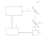
- FIG. 1 It is a block diagram which shows an example of the laser beam irradiation apparatus which concerns on this invention, and shows a schematic structure.
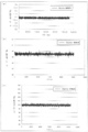
- (A), (b), and (c) show an example in which the output value of the laser beam is stabilized by the laser beam irradiation device, and the output fluctuation of the laser beam irradiated by the laser beam irradiation device is shown. It is a graph to show.
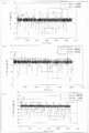
- (A), (b), (c) is a graph which shows the output fluctuation
- the output fluctuation of the laser beam irradiated by the laser beam irradiation apparatus according to the present invention is compared with the output fluctuation of the laser beam irradiated by the conventional laser beam irradiation apparatus. It is a graph.
- FIGS. 1 to 5 An embodiment of the present invention will be described with reference to FIGS. 1 to 5 as follows.
- cutting the film means not only dividing the film into at least two parts but also making a cut through the film and forming a groove (cut) having a predetermined depth in the film. "To cut at least part of” is also included. More specifically, “cutting” includes, for example, cutting (cutting off) an end portion of the film, half-cutting, marking processing, and the like.
- a laser beam irradiation apparatus 10 is an apparatus that irradiates a laser beam to the polarizing film in order to cut the polarizing film (film).
- a mirror 2 a beam splitter 3, a power sensor (measurement device) 4, a processing board (correction device) 5, and a condensing lens (not shown), and an optical member such as a beam expander (not shown) as necessary. It has more.
- the laser beam oscillator 1 is a member that oscillates a laser beam L.
- a CO 2 laser beam oscillator carbon dioxide laser beam oscillator
- a UV laser beam oscillator a UV laser beam oscillator
- a semiconductor laser beam oscillator a YAG laser beam oscillator
- An oscillator such as an excimer laser beam oscillator or the like can be used, but the specific configuration is not particularly limited.
- a CO 2 laser light oscillator is more preferable because it can oscillate laser light at a high output suitable for, for example, cutting processing of a polarizing film.
- a laser beam oscillator has a characteristic that the output of a laser beam is not constant, the output value fluctuates with a constant amplitude with a set value sandwiched in a very short period (for example, 1 millisecond), and the output is When it is low, the output value of the laser beam is likely to be unstable (the higher the output, the smaller the fluctuation range of the output value). For this reason, in order to further stabilize the output value of the laser beam oscillator 1, it is desirable to set the output of the laser beam oscillator 1 to a relatively high output.
- the output value of the laser beam oscillator 1 may be set in advance to an appropriate setting value according to conditions such as the material and thickness of the polarizing film. That is, the specific output value of the laser light oscillator 1 is an appropriate set value according to the material and thickness of the polarizing film, the conveyance speed of the polarizing film, and the ratio of transmitted light and reflected light by the beam splitter 3. It is desirable to set to.
- the frequency of the laser beam L to be irradiated may be appropriately set according to conditions such as the output of the laser beam oscillator 1, the material and thickness of the polarizing film, and the conveyance speed of the polarizing film, but is generally 5 kHz or more and 100 kHz or less. Can do.
- the laser light oscillator 1 outputs laser light in accordance with a preset setting value
- the processing board 5 that is a correction device corrects the output value so that the output value approaches the set value. ing.
- the laser light irradiation device 10 is more preferably provided with a beam expander on the optical path from the beam splitter 3 toward the polarizing film.
- the beam expander is a member that spreads the laser beam L1 into a parallel light beam, and a known beam expander can be used. Specifically, it is more preferable to widen the diameter of the laser beam L1 by, for example, about 2 to 10 times with a beam expander. By enlarging the diameter of the laser beam, the spot diameter of the laser beam irradiated on the polarizing film can be further reduced (reduced).
- the bend mirror 2 is a member that reflects the laser light L oscillated from the laser light oscillator 1 toward the beam splitter 3.
- the bend mirror 2 is preferably a plane reflecting mirror, for example, but may be any configuration that can reflect the laser light L toward the beam splitter 3. Moreover, the number is not specifically limited.
- the beam splitter 3 is a member that branches the laser light L oscillated from the laser light oscillator 1 and reflected by the bend mirror 2 into two parts at a certain ratio (ratio). That is, the beam splitter 3 is a member that branches the laser light L into the reflected light L1 and the transmitted light L2 at a constant ratio.
- the beam splitter 3 irradiates the polarized film with the reflected light L1 (one of the laser beams) out of the branched laser beam through an optical member such as a condenser lens, and is used for cutting the polarizing film.
- the transmitted light L2 (the other laser beam) is applied to the power sensor 4 to adjust the output of the laser beam oscillator 1.
- a known beam splitter can be used as the beam splitter 3.
- the condensing lens may be a known lens such as a spherical lens or an aspherical lens, and is not particularly limited.
- the cutting width (cutting distance) of the polarizing film is determined by the condensing diameter of the laser light that is the reflected light L1
- the condensing diameter of the laser light on the polarizing film is 5 ⁇ m or more and 500 ⁇ m or less. Preferably, it is 10 ⁇ m or more and 400 ⁇ m or less.
- the reflected light L1 is used for cutting the polarizing film
- the transmitted light L2 is used for adjusting the output of the laser beam oscillator 1
- the transmitted light L2 can be used for cutting the polarizing film
- the reflected light L1 can be used for adjusting the output of the laser light oscillator 1.
- a power sensor 4 as a measuring device is an element that converts the transmitted light L2 into a thermoelectromotive force and measures the intensity of the laser light that is the transmitted light L2. That is, the power sensor 4 measures the electric power generated when the laser beam is irradiated, and thereby measures the intensity of the laser beam.
- the measurement interval by the power sensor 4 is more preferably short, for example, 10 milliseconds, but is not particularly limited. Note that a known power sensor can be used as the power sensor 4.
- the measuring apparatus should just be the structure which can measure the intensity
- the power sensor 4 transmits the measured laser beam intensity (measured value) data to the processing board 5 via an A / D converter (not shown).
- the A / D converter converts analog data of measurement values into digital data, and transmits the digital data of measurement values to the processing board 5.
- the processing board 5 which is a correction device incorporates an arithmetic processing device such as a CPU (central processing unit).
- the processing board 5 is based on the measured value digital data received from the power sensor 4 via the A / D converter and the ratio (ratio) of the transmitted light L2 at the branching of the beam splitter 3.
- the output value of the laser beam oscillator 1 is calculated, and the output value of the laser beam oscillator 1 is judged to be large (over or short) with respect to a preset set value, and the output value of the laser beam oscillator 1 is corrected to full time so as to approach the set value. It has become.
- the processing board 5 feeds back the calculation result to the laser beam oscillator 1 in full time, specifically, for example, every 10 milliseconds, and the actual output value of the laser beam oscillator 1 approaches the set value. Adjustment (correction) is made as follows. More specifically, when the intensity of the laser beam that is the transmitted light L2 is small and the output value of the laser beam oscillator 1 is smaller than the set value, the laser is set so that the actual output value of the laser beam L is increased.
- the processing board 5 only needs to have a configuration capable of performing the above calculation and determination, and therefore the specific configuration is not limited to a specific configuration.
- the intensity of the transmitted light L2 is measured at a measurement interval of, for example, 10 milliseconds, and the output value of the laser beam L is adjusted by the power sensor 4 and the processing board 5 configured as described above. Since the so-called FTS (full time stabilizer) system is used to adjust (correct) the actual output value of the laser light oscillator 1 so as to approach the set value, the polarizing film can be cut appropriately. .
- FTS full time stabilizer
- the laser beam irradiation apparatus 10 is used as one apparatus constituting, for example, a slitter machine (not shown) that continuously cuts a polarizing film.
- the slitter machine in addition to the laser irradiation device 10, an unwinding unit for unwinding a long polarizing film (described later), a plurality of transport rolls for transporting the polarizing film, and a winding for winding the cut polarizing film A member such as a section is provided.
- the slitter machine will be described.
- the configuration other than the laser irradiation apparatus 10 in the slitter machine can employ a known configuration, the description thereof will be simplified.
- the unwinding part is a member that holds the long polarizing film and unwinds the polarizing film toward the transport roll by being rotated by a rotating device, and specifically includes a known unwinding part.
- tensile_strength added to a polarizing film and the conveyance speed of a polarizing film are adjusted with a rotating apparatus.
- one unwinding portion may be installed, but by installing two unwinding portions, before the polarizing film of one unwinding portion is completely unwound, the polarizing film is connected to the polarizing film of the other unwinding portion. Since it can connect, the time which replace
- a conveyance roll which conveys a polarizing film As a conveyance roll which conveys a polarizing film, a well-known conveyance roll is mentioned. Usually, the width of the transport roll is about 1.5 m to 2.5 m. Although the conveyance speed of a polarizing film should just be 1 m / sec or more and 100 m / sec or less, for example, it is not specifically limited. Moreover, the slitter machine may be provided with a touch roll that presses the polarizing film against the transport roll.
- Two winding units are installed, and are members that wind up a polarizing film that has been cut by being rotated by a rotating device. Specific examples include a known winding unit. The tension applied to the cut polarizing film and the conveying speed of the polarizing film are adjusted by a rotating device.
- the laser irradiation device 10 is disposed in the middle of a polarizing film transport path formed by a plurality of transport rolls, and continuously cuts the polarizing film transported by the transport rolls. In addition, you may perform the cutting process of a polarizing film, moving the laser irradiation apparatus 10 instead of moving a polarizing film.
- the polarizing film can be continuously cut by using the slitting machine having the above configuration.
- disconnects is not specifically limited, A well-known polarizing film can be mentioned.
- the polarizing film include a long polarizing film (for example, a polarizing film having a length of 10 m or more in the cutting direction), but a short film (for example, a polarizing film having a length of 2 m or more and less than 10 m in the cutting direction).
- the polarizing film of plate shape (For example, the length of the polarizing film in a cutting direction is 10 cm or more and less than 2 m) may be sufficient.
- the polarizing film has a film such as a TAC (triacetyl cellulose) film or a COP (cycloolefin polymer) film as a protective film member on both surfaces of the polarizer film, and a laser.
- a film such as a TAC (triacetyl cellulose) film or a COP (cycloolefin polymer) film as a protective film member on both surfaces of the polarizer film, and a laser.
- stacked through the adhesive on the TAC film of the reverse surface (back surface) with respect to the irradiation apparatus 10 can be mentioned.
- a polarizer film located in the center of a polarizing film the film by which the protective film members, such as TAC, were bonded to the film by which the polyvinyl alcohol film was dye
- hydrophilic polymer films such as partially formalized polyvinyl alcohol films, ethylene / vinyl acetate copolymer partially saponified films, and cellulose films, polyvinyl alcohol dehydrated products and polychlorinated
- a polyene oriented film such as a dehydrochlorinated product of vinyl can also be used.
- the protective film a film such as a polyester film or a polyethylene terephthalate film can also be used.
- the thickness and width of the protective film are not particularly limited, but from the viewpoint of being used as a protective film for a polarizing film, for example, the thickness is 5 ⁇ m or more and 60 ⁇ m or less, and the width is 200 mm or more and 1500 mm or less. It is preferable that
- the thickness of the polarizing film including the protective film is not particularly limited, but may be 100 ⁇ m or more and 500 ⁇ m or less. In addition, the thickness of the polarizer film is generally 10 ⁇ m or more and 50 ⁇ m or less. Furthermore, the polarizing film may further contain other layers in addition to the above three layers (polarizer film, TAC film and COP film, protective film) as long as there is no practical problem.
- the laser light irradiation method is a method of irradiating the polarizing film with a laser beam in order to cut the polarizing film (film), and two laser lights L oscillated from the laser light oscillator 1 are used.
- the reflected light L1 (one laser light) of the branched laser light is irradiated to the polarizing film through an optical member such as a condenser lens and used for cutting the polarizing film.
- the intensity of the laser light that is the transmitted light L2 (the other laser light) is measured, and the measured intensity (for example, digital data of the measured value) and the ratio (ratio) of the transmitted light L2 at the branching by the beam splitter 3
- the output value of the laser light oscillator 1 is calculated, and the magnitude (excess or deficiency) of the output value with respect to a preset set value is determined. So as to approach the output value to the set value is a method for full-time correction.
- the laser beam L a CO 2 laser beam is more preferable because a high output suitable for, for example, a cutting process of a polarizing film can be obtained.
- the frequency of the laser light L to be irradiated may be appropriately set depending on conditions such as the output of the laser light oscillator 1, the material and thickness of the polarizing film, and the conveying speed of the polarizing film, but is generally 5 kHz or more and 100 kHz or less. can do.
- the beam splitter 3 may be used as described above.
- the branching method is not limited to the method using the beam splitter, and any method can be used as long as the laser light L can be branched into two.
- the ratio between the reflected light L1 and the transmitted light L2 may be set to an appropriate setting value according to conditions such as the output of the laser light oscillator 1, the material and thickness of the polarizing film, the conveyance speed of the polarizing film, It is not particularly limited.
- the reflected light L1 is used for cutting the film and the transmitted light L2 is used for adjusting the output of the laser light oscillator 1.
- L2 may be used for cutting the film, and the reflected light L1 may be used for adjusting the output of the laser light oscillator 1.
- the power sensor 4 may be used as described above.
- the measuring method is not limited to the method using the power sensor, and any method that can measure the intensity of the laser beam may be used.
- the measurement interval is preferably shorter, for example, 10 milliseconds, but is not particularly limited.
- the processing board 5 may be used as described above.
- the correction method is not limited to the method using the processing board.
- the intensity of the measured laser beam for example, digital data of the measured value
- the ratio (ratio) of the transmitted light L2 and the preset settings
- the calculation result using the value is fed back to the laser beam oscillator 1 every 10 milliseconds, for example, and the actual output value of the laser beam oscillator 1 can be adjusted (corrected) so as to approach the set value. Any method can be used.
- the laser is set so that the actual output value of the laser beam L is increased.
- the output of the optical oscillator 1 is adjusted, while the intensity of the laser light that is the transmitted light L2 is large and the output value of the laser optical oscillator 1 is larger than the set value, the actual output value of the laser light L Any method can be used as long as the output of the laser beam oscillator 1 can be adjusted so as to be small.
- a so-called FTS (full time stabilizer) system that measures the intensity of the transmitted light L2 at a measurement interval of 10 milliseconds and adjusts the output value of the laser beam L is adopted. Since the actual output value of the laser beam oscillator 1 can be adjusted (corrected) so as to approach the set value, the polarizing film can be appropriately cut.
- the laser light irradiation method according to the present embodiment can be suitably used for, for example, a slitter machine that continuously performs a cutting process on a polarizing film.
- the laser beam irradiation apparatus and the laser beam irradiation method according to the present invention are an apparatus and a method that can appropriately cut a film, it can also be understood that they are a laser beam cutting apparatus and a laser beam cutting method. .
- the performance of the laser beam irradiation apparatus 10 according to this embodiment was examined. Moreover, in order to contrast with the performance of the laser beam irradiation apparatus 10 which concerns on this embodiment, the performance of the conventional laser beam irradiation apparatus was examined. Specifically, the output fluctuation of the laser beam L oscillated from the laser beam oscillator 1 of the laser beam irradiation apparatus 10 according to the present embodiment and the conventional laser beam irradiation apparatus was measured.
- Fig. 3 shows the configuration of the laser beam irradiation device whose performance was examined.
- the conventional laser beam irradiation apparatus 20 includes a laser beam oscillator 1, a bend mirror 2, a bend mirror 8, and a condenser lens (not shown). That is, the conventional laser beam irradiation apparatus 20 does not include a beam splitter, a power sensor, an A / D converter, and a processing board, and all of the laser beam L oscillated from the laser beam oscillator 1 is sent to the bend mirror 2 and the bend. The light is reflected by the mirror 8 and used for cutting the film.
- the laser beam irradiation apparatus 20 has a configuration (for example, an optical member such as a beam expander) other than the configuration for correcting the output value of the laser beam oscillator 1 to be close to a set value.
- the laser beam oscillator 1 used the same oscillator by the laser beam irradiation apparatus 10 and the laser beam irradiation apparatus 20.
- the output fluctuation of the laser beam L oscillated from the laser beam oscillator 1 was measured using the laser beam irradiation device 10 according to the present embodiment and the conventional laser beam irradiation device 20.
- the output value of the laser beam L oscillated from the laser beam oscillator 1 was set to 14.0 W, and the film was cut at a speed of 6 m / min.
- the output value of the actually output laser beam L is generally within the range of 13.4 to 14.1 W (average). 13.8W, runout width 0.7W).
- the output value of the actually output laser beam L varies within a range of 12.3 to 15.0 W in general. (Average 13.8W, runout 2.7W). Therefore, as is apparent from the result shown in FIG.
- the laser beam L oscillated from the laser beam oscillator 1 of the laser beam irradiation apparatus 10.
- the output fluctuation of the laser beam irradiation apparatus 10 according to the present embodiment was small, and it was found that the performance of the laser beam irradiation apparatus 10 according to the present embodiment was remarkably superior to that of the conventional laser beam irradiation apparatus 20.
- the output value of the laser beam L oscillated from the laser beam oscillator 1 was set to 49.5 W, and the film was cut at a speed of 30 m / min.
- the output value of the actually output laser beam L is generally within the range of 48.9 to 50.4 W (average). 49.5W, runout width 1.6W).
- the output value of the actually output laser beam L generally varies within the range of 46.4 to 51.1W. (Average 49.2W, runout 4.7W). Therefore, as is apparent from the result shown in FIG.
- the output value of the laser beam L oscillated from the laser beam oscillator 1 was set to 100.0 W, and the film was cut at a speed of 60 m / min.
- the output value of the actually output laser beam L is generally within the range of 99.3 to 100.6 W (average) 99.9W, runout width 1.3W).
- the output value of the actually output laser beam L generally varies within the range of 95.2 to 102.8W. (Average 99.1W, runout 7.6W). Therefore, as is apparent from the result shown in FIG.
- the performance of the laser light irradiation apparatus 10 according to the present embodiment is higher than that of the conventional laser light irradiation apparatus 20 from the laser light oscillator 1. Since the output fluctuation of the oscillated laser beam L is small, it is clear that it is remarkably excellent.
- the laser beam irradiation apparatus and the laser beam irradiation method according to the present invention even if the output value of the laser beam is set to a value necessary (and lower) for cutting the film, output fluctuation is suppressed. Therefore, the output value does not become lower than a certain value (smaller) than the set value, and the film can be cut appropriately. Therefore, it is possible to provide a laser light irradiation apparatus and a laser light irradiation method capable of suppressing output fluctuation (fluctuation with respect to a set value), stabilizing the output of the laser light to be irradiated, and appropriately cutting the film. There is an effect.
- the laser light irradiation apparatus and laser light irradiation method according to the present invention can be used for, for example, cutting processing of a polarizing film, so in the manufacturing process of various products such as a liquid crystal panel using the polarizing film, That is, it can be widely used in various industries using a polarizing film.
- Laser oscillator 2 Bend mirror 3 Beam splitter 4 Power sensor (measuring device) 5 processing board (correction device) 10 Laser light irradiation device L Laser light L1 Reflected light (laser light) L2 Transmitted light (laser light)
Landscapes
- Engineering & Computer Science (AREA)
- Physics & Mathematics (AREA)
- Optics & Photonics (AREA)
- Mechanical Engineering (AREA)
- Plasma & Fusion (AREA)
- Health & Medical Sciences (AREA)
- Manufacturing & Machinery (AREA)
- Ophthalmology & Optometry (AREA)
- Laser Beam Processing (AREA)
- Polarising Elements (AREA)
Abstract
出力変動が抑制され、照射するレーザー光の出力が安定化されたレーザー光照射装置およびレーザー光照射方法を提供する。フィルムを切断するために当該フィルムにレーザー光を照射するレーザー光照射装置(10)は、レーザー光Lを発振するレーザー光発振機(1)と、レーザー光発振機(1)から発振されたレーザー光Lを二つに分岐し、反射光L1であるレーザー光をフィルムに照射するビームスプリッター(3)と、透過光L2であるレーザー光の強度を測定するパワーセンサー(4)と、測定された強度からレーザー光発振機(1)の出力値を算出し、設定値に対する上記出力値の大小を判断して、レーザー光発振機(1)の出力値を設定値に近づけるように補正する処理ボード(5)と、を備えている。
Description
本発明は、出力変動が抑制され、照射するレーザー光の出力が安定化されてフィルムを適切に切断することができるレーザー光照射装置およびレーザー光照射方法に関するものである。
偏光フィルムは液晶パネル等の各種製品に広く用いられている。従来、偏光フィルムの切断加工には刃物が用いられているものの、被切断物からフィルム屑等の異物が生じ易く、この異物が偏光フィルムに付着することにより、被切断物である製品の歩留まりが低下してしまう。
そこで、近年、偏光フィルムの切断加工には、刃物に代わってレーザー光が使用されている。レーザー光で切断加工を行うことにより、刃物による切断加工と比較して、被切断物からフィルム屑等の異物が生じ難くなるので、被切断物である製品の歩留まりの低下を抑制することができる。このため、レーザー光による切断方法は有用であり、例えば特許文献1~5に記載されているように、種々の方法が提案されている。
ところで、一般に、レーザー光発振機は、レーザー光の出力が一定ではなく、ごく短い周期(例えば1ミリ秒)で、出力値が設定値を挟んだ一定の振幅で変動するという特性を有している。それゆえ、レーザー光発振機の出力変動により、偏光フィルムを切断加工するのに必要な値にレーザー光の出力値を設定していても、実際には偏光フィルムを適切に切断加工することができない場合があるという問題点を有している。当該問題点について、以下に具体的に説明する。
通常、偏光フィルムの切断加工は、偏光フィルムの長尺物を一定の速度で搬送しながらレーザー光を照射することによって連続的に行われる。ここで、レーザー光の出力値を偏光フィルムの切断加工に必要な(かつ、より低い)値に設定すると、出力変動によって当該出力値が設定値よりも一定以上低く(小さく)なったときには、偏光フィルムが切断されなくなってしまう。それゆえ、切断加工後の偏光フィルムを巻回するときに当該偏光フィルムの端部(切断部)が引き千切られた状態になったり、端部から偏光フィルム内側に向かって破れたりするという不都合が発生することとなる。一方、上記不都合を解消するために、即ち、出力値が設定値よりも一定以上低くなったときにおいても切断加工ができるように、レーザー光の出力値を偏光フィルムの切断加工に必要な値よりも高い値に設定すると、出力変動によって当該出力値が設定値よりも一定以上高く(大きく)なったときには、出力値が高くなり過ぎ、偏光フィルムの端部(切断部)がレーザー光の照射による過剰な熱で溶解したり、熱膨張して盛り上がったり反り返ったりしてしまう。それゆえ、切断加工後の偏光フィルムにおいて品質の劣化が生じるという別の不都合が発生することとなる。
しかしながら、上記特許文献1~5に記載されている切断方法においては、レーザー光発振機の上記特性、即ち、ごく短い周期で、レーザー光の出力が変動するという特性について、特段の考慮や対策は行われていない。つまり、上記特許文献1~5に記載されている切断方法においては、偏光フィルムを適切に切断加工することができない場合があるという問題点を有している。それゆえ、偏光フィルムを常時、適切に切断加工することができるレーザー光照射装置およびレーザー光照射方法が求められている。
本発明は、上記課題に鑑みてなされたものであり、その主たる目的は、出力変動が抑制され、照射するレーザー光の出力が安定化されたレーザー光照射装置およびレーザー光照射方法を提供することにある。
本発明に係るレーザー光照射装置は、上記課題を解決するために、フィルムを切断するために当該フィルムにレーザー光を照射するレーザー光照射装置であって、レーザー光を発振するレーザー光発振機と、レーザー光発振機から発振されたレーザー光を二つに分岐し、分岐させたレーザー光のうちの、一方のレーザー光をフィルムに照射するビームスプリッターと、分岐されたレーザー光のうちの、他方のレーザー光の強度を測定する測定装置と、測定された強度から上記レーザー光発振機の出力値を算出し、設定値に対する上記出力値の大小を判断して、上記レーザー光発振機の出力値を設定値に近づけるように補正する補正装置と、を備えている。
上記構成によれば、ビームスプリッターによって分岐されたレーザー光のうちの、他方のレーザー光の強度を測定装置で測定し、補正装置で上記強度からレーザー光発振機の出力値を算出し、設定値に対する上記出力値の大小を判断して、上記レーザー光発振機の出力値を設定値に近づけるように補正することができる。従って、上記レーザー光照射装置から発振されるレーザー光の出力値を、フィルムを切断するのに必要な(かつ、より低い)値に設定しても、出力変動が抑制されるので当該出力値が設定値よりも一定以上低く(小さく)なることはなく、フィルムを適切に切断することができる。それゆえ、出力変動(設定値に対する変動)が抑制され、照射するレーザー光の出力が安定化されてフィルムを適切に切断することができるレーザー光照射装置を提供することができる。
上記測定装置は、分岐されたレーザー光のうちの、透過光の強度を測定するようになっていることがより好ましい。また、上記測定装置がパワーセンサーであることがより好ましい。さらに、上記レーザー光発振機がCO2 レーザー光発振機であることがより好ましい。
本発明に係るレーザー光照射方法は、上記課題を解決するために、フィルムを切断するために当該フィルムにレーザー光を照射するレーザー光照射方法であって、レーザー光発振機から発振されたレーザー光を二つに分岐させ、分岐させたレーザー光のうちの、一方のレーザー光をフィルムに照射すると共に、他方のレーザー光の強度を測定し、測定した強度から上記レーザー光発振機の出力値を算出し、設定値に対する上記出力値の大小を判断して、上記レーザー光発振機の出力値を設定値に近づけるようにフルタイム補正することを含む。
上記構成によれば、分岐されたレーザー光のうちの、他方のレーザー光の強度を測定し、上記強度からレーザー光発振機の出力値を算出し、設定値に対する上記出力値の大小を判断して、上記レーザー光発振機の出力値を設定値に近づけるようにフルタイム補正する。従って、上記レーザー光照射装置から発振されるレーザー光の出力値を、フィルムを切断するのに必要な(かつ、より低い)値に設定しても、出力変動が抑制されるので当該出力値が設定値よりも一定以上低く(小さく)なることはなく、フィルムを適切に切断することができる。それゆえ、出力変動(設定値に対する変動)が抑制され、照射するレーザー光の出力が安定化されてフィルムを適切に切断することができるレーザー光照射方法を提供することができる。
本発明に係るレーザー光照射装置およびレーザー光照射方法によれば、レーザー光の出力値を、フィルムを切断するのに必要な(かつ、より低い)値に設定しても、出力変動が抑制されるので当該出力値が設定値よりも一定以上低く(小さく)なることはなく、フィルムを適切に切断することができる。それゆえ、出力変動(設定値に対する変動)が抑制され、照射するレーザー光の出力が安定化されてフィルムを適切に切断することができるレーザー光照射装置およびレーザー光照射方法を提供することができるという効果を奏する。
本発明に係るレーザー光照射装置およびレーザー光照射方法によって切断されたフィルムは、その端部(切断部)が引き千切られた状態になったり、端部から偏光フィルム内側に向かって破れたりすることはなく、しかも、レーザー光の出力値が必要以上に高く設定されていないため、溶解したり、熱膨張して盛り上がったり反り返ったりすることもない。それゆえ、切断加工後のフィルムにおいては、品質の劣化が生じるおそれはない。
本発明の実施の一形態について、図1~図5に基づいて説明すれば、以下の通りである。
尚、以下の説明においては、切断されるフィルムが偏光フィルムである場合を例に挙げることとする。また、本発明においてフィルムを「切断する」とは、フィルムを少なくとも二つに分割することの他に、フィルムに貫通する切れ目を入れることやフィルムに所定の深さの溝(切れ込み)を形成すること等の「少なくとも一部を切断する」ことも包含されていることとする。より具体的には、「切断する」には、例えば、フィルムの端部の切断(切り落とし)、ハーフカット、マーキング加工等も含まれることとする。
〔レーザー光照射装置〕
本発明に係るレーザー光照射装置の一例を図1に示す。図1に示すように、本実施形態に係るレーザー光照射装置10は、偏光フィルム(フィルム)を切断するために当該偏光フィルムにレーザー光を照射する装置であって、レーザー光発振機1、ベンドミラー2、ビームスプリッター3、パワーセンサー(測定装置)4、処理ボード(補正装置)5、および集光レンズ(図示しない)を備えると共に、必要に応じてビームエキスパンダー(図示しない)等の光学部材をさらに備えている。
本発明に係るレーザー光照射装置の一例を図1に示す。図1に示すように、本実施形態に係るレーザー光照射装置10は、偏光フィルム(フィルム)を切断するために当該偏光フィルムにレーザー光を照射する装置であって、レーザー光発振機1、ベンドミラー2、ビームスプリッター3、パワーセンサー(測定装置)4、処理ボード(補正装置)5、および集光レンズ(図示しない)を備えると共に、必要に応じてビームエキスパンダー(図示しない)等の光学部材をさらに備えている。
レーザー光発振機1は、レーザー光Lを発振する部材であり、例えば、CO2 レーザー光発振機(二酸化炭素レーザー光発振機)、UVレーザー光発振機、半導体レーザー光発振機、YAGレーザー光発振機、エキシマレーザー光発振機等の発振機を用いることができるが、具体的な構成は特に限定されるものではない。上記例示の発振機の中でもCO2 レーザー光発振機は、例えば偏光フィルムの切断加工に好適な高出力でレーザー光を発振することができるので、より好ましい。
一般に、レーザー光発振機は、レーザー光の出力が一定ではなく、ごく短い周期(例えば1ミリ秒)で、出力値が設定値を挟んだ一定の振幅で変動するという特性を有すると共に、出力が低い場合にはレーザー光の出力値が不安定となり易い(出力が高いほど出力値の変動幅が小さくなり易い)という特性も有している。このため、レーザー光発振機1の出力値をより一層安定化させるには、レーザー光発振機1の出力を比較的高出力にすることが望ましい。但し、出力値が高すぎると、偏光フィルムがレーザー光の照射による過剰な熱で溶解したり、熱膨張して盛り上がったり反り返ったりしてしまい、切断加工後の偏光フィルムにおいて品質の劣化が生じるおそれがある。それゆえ、レーザー光発振機1の出力値は、偏光フィルムの材質や厚さ等の条件に応じた適切な設定値に予め設定すればよい。即ち、レーザー光発振機1の具体的な出力値は、偏光フィルムの材質や厚さ、偏光フィルムの搬送速度、並びに、ビームスプリッター3による透過光および反射光の比率に応じて、適切な設定値に設定することが望ましい。
照射するレーザー光Lの周波数は、レーザー光発振機1の出力、偏光フィルムの材質や厚さ、偏光フィルムの搬送速度等の条件により適宜設定すればよいが、概して5kHz以上、100kHz以下とすることができる。
そして、レーザー光発振機1は、予め設定された設定値に従ってレーザー光を出力すると共に、補正装置である処理ボード5によって、その出力値が設定値に近づくようにフルタイム補正されるようになっている。
レーザー光照射装置10は、ビームスプリッター3から偏光フィルムに向かう光路上に、ビームエキスパンダーを備えていることがより好ましい形態である。ビームエキスパンダーは、レーザー光L1を平行光束に広げる部材であり、公知のビームエキスパンダーを使用することができる。具体的には、ビームエキスパンダーにより、レーザー光L1の直径を例えば2倍~10倍程度に広げることがより好ましい。レーザー光の直径を拡大することによって、偏光フィルムに照射するレーザー光のスポット径をより絞る(小さくする)ことができる。
ベンドミラー(bent mirror) 2は、レーザー光発振機1から発振されたレーザー光Lをビームスプリッター3に向けて反射する部材である。上記ベンドミラー2は、例えば平面反射鏡が好適であるが、レーザー光Lをビームスプリッター3に向けて反射することができる構成であればよい。また、その個数は特に限定されるものではない。
ビームスプリッター(beam splitter) 3は、レーザー光発振機1から発振されベンドミラー2にて反射されたレーザー光Lを、一定の比率(割合)で二つに分岐する部材である。即ち、ビームスプリッター3は、レーザー光Lを、一定の比率で反射光L1と透過光L2とに分岐する部材である。そして、ビームスプリッター3は、分岐させたレーザー光のうちの、反射光L1(一方のレーザー光)を、集光レンズ等の光学部材を介して偏光フィルムに照射して偏光フィルムの切断加工に使用すると共に、透過光L2(他方のレーザー光)を、パワーセンサー4に照射してレーザー光発振機1の出力調節に使用するようになっている。当該ビームスプリッター3は、公知のビームスプリッターを使用することができる。
上記集光レンズは、例えば球面レンズや非球面レンズ等の公知のレンズを使用すればよく、特に限定されるものではない。尚、反射光L1であるレーザー光の集光径によって偏光フィルムの切断幅(切りしろ)が決定されることになるため、偏光フィルム上における当該レーザー光の集光径は、5μm以上、500μm以下であることが好ましく、10μm以上、400μm以下であることがより好ましい。
尚、本実施形態に係るレーザー光照射装置10においては、反射光L1を偏光フィルムの切断加工に使用し、透過光L2をレーザー光発振機1の出力調節に使用する構成となっているが、例えばベンドミラー(図示しない)を用いることにより、透過光L2を偏光フィルムの切断加工に使用し、反射光L1をレーザー光発振機1の出力調節に使用する構成とすることもできる。
測定装置としてのパワーセンサー(power sensor)4は、透過光L2を熱起電力に変換し、透過光L2であるレーザー光の強度を測定する素子である。つまり、パワーセンサー4は、レーザー光が照射されることによって発生する電力を測定し、これにより当該レーザー光の強度を測定するようになっている。パワーセンサー4による測定間隔は短い方がより好ましく、例えば10ミリ秒とすればよいが、特に限定されるものではない。尚、パワーセンサー4は、公知のパワーセンサーを使用することができる。また、測定装置は、レーザー光の強度を測定することができる構成であればよい。
そして、パワーセンサー4は、測定したレーザー光の強度(測定値)のデータを、A/Dコンバータ(図示しない)を介して処理ボード5に送信する。上記A/Dコンバータは、測定値のアナログデータをデジタルデータに変換し、測定値のデジタルデータを処理ボード5に送信する。
補正装置である処理ボード5は、CPU(central processing unit) 等の演算処理装置を内蔵している。当該処理ボード5は、パワーセンサー4からA/Dコンバータを介して受信した測定値のデジタルデータと、ビームスプリッター3での分岐における透過光L2の比率(割合)とから、上記レーザー光発振機1の出力値を算出し、予め設定された設定値に対する上記出力値の大小(過不足)を判断して、上記レーザー光発振機1の出力値を設定値に近づけるようにフルタイム補正するようになっている。つまり、処理ボード5は、演算結果をレーザー光発振機1にフルタイムで、具体的には例えば10ミリ秒毎にフィードバックして、レーザー光発振機1の実際の出力値を、設定値に近づくように調節(補正)するようになっている。より具体的には、透過光L2であるレーザー光の強度が小さく、レーザー光発振機1の出力値が設定値よりも小さい場合には、レーザー光Lの実際の出力値が大きくなるようにレーザー光発振機1の出力を調節し、一方、透過光L2であるレーザー光の強度が大きく、レーザー光発振機1の出力値が設定値よりも大きい場合には、レーザー光Lの実際の出力値が小さくなるようにレーザー光発振機1の出力を調節する。尚、処理ボード5は、上記算出および判断を行うことができる構成であればよく、従ってその具体的な構成は、特定の構成に限定されるものではない。
本実施形態に係るレーザー光照射装置10においては、上記構成のパワーセンサー4および処理ボード5により、例えば10ミリ秒の測定間隔で透過光L2の強度を測定し、レーザー光Lの出力値を調節するいわゆるFTS(full time stabilizer)システムを採用してレーザー光発振機1の実際の出力値を設定値に近づくように調節(補正)することができるので、偏光フィルムを適切に切断することができる。
本実施形態に係るレーザー光照射装置10は、例えば、偏光フィルムの切断加工を連続的に行うスリッター機(図示しない)を構成する一装置として使用される。スリッター機は、レーザー照射装置10の他に、長尺の偏光フィルム(後述する)を巻き出す巻出部、当該偏光フィルムを搬送する複数の搬送ロール、切断加工された偏光フィルムを巻き取る巻取部等の部材を備えている。以下、スリッター機について説明する。但し、スリッター機におけるレーザー照射装置10以外の構成は、公知の構成を採用することができるので、その説明を簡略化することとする。
巻出部は、長尺の偏光フィルムを保持すると共に、回転装置により回転されることによって偏光フィルムを搬送ロールに向かって巻き出す部材であり、具体的には公知の巻出部が挙げられる。尚、偏光フィルムに加わる張力および偏光フィルムの搬送速度は、回転装置によって調節される。また、巻出部は一つ設置すればよいが、二つ設置することにより、一方の巻出部の偏光フィルムが全て巻き出される前に、当該偏光フィルムを他方の巻出部の偏光フィルムと連結することができるので、偏光フィルムの原反を交換する時間を削減することができる。
偏光フィルムを搬送する搬送ロールとしては、公知の搬送ロールが挙げられる。通常、搬送ロールの幅は、1.5m~2.5m程度である。偏光フィルムの搬送速度は、例えば、1m/秒以上、100m/秒以下とすればよいが、特に限定されるものではない。また、スリッター機には、偏光フィルムを搬送ロールに押し当てるタッチロールが備えられていてもよい。
巻取部は、二つ設置されており、回転装置により回転されることによって切断加工された偏光フィルムを巻き取る部材であり、具体的には公知の巻取部が挙げられる。尚、切断加工された偏光フィルムに加わる張力および偏光フィルムの搬送速度は、回転装置によって調節される。
レーザー照射装置10は、複数の搬送ロールによって形成される偏光フィルムの搬送経路の途中に配設されており、搬送ロールによって搬送される偏光フィルムを連続的に切断加工する。尚、偏光フィルムの切断加工は、偏光フィルムを移動させる代りにレーザー照射装置10を移動させながら行ってもよい。
従って、上記構成のスリッター機を用いることにより、偏光フィルムを連続的に切断加工することができる。
〔フィルム〕
レーザー照射装置10が切断するフィルム(切断対象)は、特に限定されるものではないが、公知の偏光フィルムを挙げることができる。当該偏光フィルムとしては、通常、長尺(例えば切断方向における偏光フィルムの長さが10m以上)の偏光フィルムが挙げられるが、短尺(例えば切断方向における偏光フィルムの長さが2m以上、10m未満)または板状(例えば切断方向における偏光フィルムの長さが10cm以上、2m未満)の偏光フィルムであってもよい。
レーザー照射装置10が切断するフィルム(切断対象)は、特に限定されるものではないが、公知の偏光フィルムを挙げることができる。当該偏光フィルムとしては、通常、長尺(例えば切断方向における偏光フィルムの長さが10m以上)の偏光フィルムが挙げられるが、短尺(例えば切断方向における偏光フィルムの長さが2m以上、10m未満)または板状(例えば切断方向における偏光フィルムの長さが10cm以上、2m未満)の偏光フィルムであってもよい。
偏光フィルムの構成としては、具体的には、例えば、偏光子フィルムの両面に保護フィルム部材としてTAC(トリアセチルセルロース)フィルム、COP(シクロオレフィンポリマー)フィルム等のフィルムが貼合されており、レーザー照射装置10に対する面の逆面(裏面)のTACフィルムに、粘着剤を介して保護フィルムが積層された構成を挙げることができる。偏光フィルムの中心に位置する偏光子フィルムとしては、ポリビニルアルコールフィルムにヨウ素等の染色剤によって染色がなされて延伸されたフィルムに、TAC等の保護フィルム部材が貼合されたフィルムを挙げることができる。また、上記ポリビニルアルコールフィルムに代えて、部分ホルマール化ポリビニルアルコール系フィルム、エチレン・酢酸ビニル共重合体系部分ケン化フィルム、セルロース系フィルム等の親水性高分子フィルム、ポリビニルアルコールの脱水処理物やポリ塩化ビニルの脱塩酸処理物等のポリエン配向フィルムを使用することもできる。
上記保護フィルムとしては、ポリエステルフィルム、ポリエチレンテレフタラートフィルム等のフィルムを用いることもできる。上記保護フィルムの厚さおよび幅は、特に限定されるものではないが、偏光フィルムの保護フィルムとして用いられる観点から、例えば、5μm以上、60μm以下の厚さであり、200mm以上、1500mm以下の幅であることが好ましい。
保護フィルムを含めた偏光フィルムの厚さは、特に限定されるものではないが、100μm以上、500μm以下とすることができる。尚、偏光子フィルムの厚さは、概して10μm以上、50μm以下である。さらに、偏光フィルムは、実用上、問題が無い範囲において、上記三層(偏光子フィルム、TACフィルムおよびCOPフィルム、保護フィルム)以外にさらに他の層を含んでいてもよい。
〔レーザー光照射方法〕
本実施形態に係るレーザー光照射方法は、偏光フィルム(フィルム)を切断するために当該偏光フィルムにレーザー光を照射する方法であって、レーザー光発振機1から発振されたレーザー光Lを二つに分岐させ、分岐させたレーザー光のうちの、例えば、反射光L1(一方のレーザー光)を、集光レンズ等の光学部材を介して偏光フィルムに照射して当該偏光フィルムの切断加工に使用すると共に、透過光L2(他方のレーザー光)であるレーザー光の強度を測定し、測定した強度(例えば測定値のデジタルデータ)と、ビームスプリッター3での分岐における透過光L2の比率(割合)とから、上記レーザー光発振機1の出力値を算出し、予め設定された設定値に対する上記出力値の大小(過不足)を判断して、上記レーザー光発振機1の出力値を設定値に近づけるようにフルタイム補正する方法である。
本実施形態に係るレーザー光照射方法は、偏光フィルム(フィルム)を切断するために当該偏光フィルムにレーザー光を照射する方法であって、レーザー光発振機1から発振されたレーザー光Lを二つに分岐させ、分岐させたレーザー光のうちの、例えば、反射光L1(一方のレーザー光)を、集光レンズ等の光学部材を介して偏光フィルムに照射して当該偏光フィルムの切断加工に使用すると共に、透過光L2(他方のレーザー光)であるレーザー光の強度を測定し、測定した強度(例えば測定値のデジタルデータ)と、ビームスプリッター3での分岐における透過光L2の比率(割合)とから、上記レーザー光発振機1の出力値を算出し、予め設定された設定値に対する上記出力値の大小(過不足)を判断して、上記レーザー光発振機1の出力値を設定値に近づけるようにフルタイム補正する方法である。
上記レーザー光Lとしては、CO2 レーザー光が、例えば偏光フィルムの切断加工に好適な高出力を得ることができるので、より好ましい。また、照射するレーザー光Lの周波数は、レーザー光発振機1の出力、偏光フィルムの材質や厚さ、偏光フィルムの搬送速度等の条件により適宜設定すればよいが、概して5kHz以上、100kHz以下とすることができる。
レーザー光Lを二つに分岐させるには、上述した通りビームスプリッター3を用いればよい。但し、分岐方法はビームスプリッターを用いた方法に限定されるものではなく、レーザー光Lを二つに分岐させることができる方法であればよい。但し、反射光L1と透過光L2との比率は、レーザー光発振機1の出力、偏光フィルムの材質や厚さ、偏光フィルムの搬送速度等の条件に応じた適切な設定値とすればよく、特に限定されるものではない。
尚、本実施形態に係るレーザー光照射方法においては、反射光L1をフィルムの切断加工に使用し、透過光L2をレーザー光発振機1の出力調節に使用する構成となっているが、透過光L2をフィルムの切断加工に使用し、反射光L1をレーザー光発振機1の出力調節に使用する構成とすることもできる。
透過光L2であるレーザー光の強度を測定するには、上述した通りパワーセンサー4を用いればよい。但し、測定方法はパワーセンサーを用いた方法に限定されるものではなく、レーザー光の強度を測定することができる方法であればよい。また、測定間隔は短い方がより好ましく、例えば10ミリ秒とすればよいが、特に限定されるものではない。
レーザー光発振機1の出力値を設定値に近づけるようにフルタイム補正するには、上述した通り処理ボード5を用いればよい。但し、補正方法は処理ボードを用いた方法に限定されるものではなく、測定したレーザー光の強度(例えば測定値のデジタルデータ)と、透過光L2の比率(割合)と、予め設定された設定値とを用いた演算結果をレーザー光発振機1に例えば10ミリ秒毎にフィードバックして、レーザー光発振機1の実際の出力値を、設定値に近づくように調節(補正)することができる方法であればよい。より具体的には、透過光L2であるレーザー光の強度が小さく、レーザー光発振機1の出力値が設定値よりも小さい場合には、レーザー光Lの実際の出力値が大きくなるようにレーザー光発振機1の出力を調節し、一方、透過光L2であるレーザー光の強度が大きく、レーザー光発振機1の出力値が設定値よりも大きい場合には、レーザー光Lの実際の出力値が小さくなるようにレーザー光発振機1の出力を調節することができる方法であればよい。
本実施形態に係るレーザー光照射方法においては、例えば10ミリ秒の測定間隔で透過光L2の強度を測定し、レーザー光Lの出力値を調節するいわゆるFTS(full time stabilizer)システムを採用してレーザー光発振機1の実際の出力値を設定値に近づくように調節(補正)することができるので、偏光フィルムを適切に切断することができる。
本実施形態に係るレーザー光照射方法は、例えば、偏光フィルムの切断加工を連続的に行うスリッター機に好適に採用することができる。
尚、本発明に係るレーザー光照射装置およびレーザー光照射方法は、フィルムを適切に切断することができる装置および方法であるので、レーザー光切断装置およびレーザー光切断方法であると理解することもできる。
本実施形態に係るレーザー光照射装置10の性能を検討した。また、本実施形態に係るレーザー光照射装置10の性能と対比するために、従来のレーザー光照射装置の性能を検討した。具体的には、本実施形態に係るレーザー光照射装置10および従来のレーザー光照射装置の、レーザー光発振機1から発振されるレーザー光Lの出力変動を測定した。
性能を検討したレーザー光照射装置の構成を図3に示す。図3に示すように、従来のレーザー光照射装置20は、レーザー光発振機1、ベンドミラー2、ベンドミラー8、および集光レンズ(図示しない)を備えている。つまり、従来のレーザー光照射装置20は、ビームスプリッター、パワーセンサー、A/Dコンバータおよび処理ボードを備えておらず、レーザー光発振機1から発振されるレーザー光Lの全てをベンドミラー2およびベンドミラー8で反射して、フィルムの切断加工に使用する構成となっている。尚、レーザー光照射装置20は、上記レーザー光発振機1の出力値を設定値に近づけるように補正するための構成以外の構成(例えばビームエキスパンダー等の光学部材)については、レーザー光照射装置10と同様に備えている。また、レーザー光発振機1は、レーザー光照射装置10とレーザー光照射装置20とで同一の発振機を用いた。
そして、本実施形態に係るレーザー光照射装置10と、従来のレーザー光照射装置20とを用いて、レーザー光発振機1から発振されるレーザー光Lの出力変動を測定した。
即ち、レーザー光発振機1から発振されるレーザー光Lの出力値を14.0Wに設定し、フィルムを6m/分の速度で切断加工した。本実施形態に係るレーザー光照射装置10では、図2(a)に示すように、実際に出力されたレーザー光Lの出力値は概して13.4~14.1Wの範囲内に納まった(平均13.8W,振れ幅0.7W)。これに対して、従来のレーザー光照射装置20では、図4(a)に示すように、実際に出力されたレーザー光Lの出力値は概して12.3~15.0Wの範囲内にばらついた(平均13.8W,振れ幅2.7W)。従って、図5(a)に示す結果から明らかなように、レーザー光Lの出力値を14.0Wに設定した場合において、レーザー光照射装置10のレーザー光発振機1から発振されるレーザー光Lの出力変動は小さく、本実施形態に係るレーザー光照射装置10の性能は、従来のレーザー光照射装置20の性能と比較して、格段に優れていることが判った。
また、レーザー光発振機1から発振されるレーザー光Lの出力値を49.5Wに設定し、フィルムを30m/分の速度で切断加工した。本実施形態に係るレーザー光照射装置10では、図2(b)に示すように、実際に出力されたレーザー光Lの出力値は概して48.9~50.4Wの範囲内に納まった(平均49.5W,振れ幅1.6W)。これに対して、従来のレーザー光照射装置20では、図4(b)に示すように、実際に出力されたレーザー光Lの出力値は概して46.4~51.1Wの範囲内にばらついた(平均49.2W,振れ幅4.7W)。従って、図5(b)に示す結果から明らかなように、レーザー光Lの出力値を49.5Wに設定した場合において、レーザー光照射装置10のレーザー光発振機1から発振されるレーザー光Lの出力変動は小さく、本実施形態に係るレーザー光照射装置10の性能は、従来のレーザー光照射装置20の性能と比較して、格段に優れていることが判った。
また、レーザー光発振機1から発振されるレーザー光Lの出力値を100.0Wに設定し、フィルムを60m/分の速度で切断加工した。本実施形態に係るレーザー光照射装置10では、図2(c)に示すように、実際に出力されたレーザー光Lの出力値は概して99.3~100.6Wの範囲内に納まった(平均99.9W,振れ幅1.3W)。これに対して、従来のレーザー光照射装置20では、図4(c)に示すように、実際に出力されたレーザー光Lの出力値は概して95.2~102.8Wの範囲内にばらついた(平均99.1W,振れ幅7.6W)。従って、図5(c)に示す結果から明らかなように、レーザー光Lの出力値を100.0Wに設定した場合において、レーザー光照射装置10のレーザー光発振機1から発振されるレーザー光Lの出力変動は小さく、本実施形態に係るレーザー光照射装置10の性能は、従来のレーザー光照射装置20の性能と比較して、格段に優れていることが判った。
即ち、図5(a)~(c)に示す結果から、本実施形態に係るレーザー光照射装置10の性能は、従来のレーザー光照射装置20の性能と比較して、レーザー光発振機1から発振されるレーザー光Lの出力変動が小さいので、格段に優れていることが明らかである。
尚、本発明は、上述した実施形態に限定されるものではなく、記述した範囲内で種々の変形を加えた態様で実施することができ、従って、請求項に示した範囲で種々の変更が可能である。
本発明に係るレーザー光照射装置およびレーザー光照射方法によれば、レーザー光の出力値を、フィルムを切断するのに必要な(かつ、より低い)値に設定しても、出力変動が抑制されるので当該出力値が設定値よりも一定以上低く(小さく)なることはなく、フィルムを適切に切断することができる。それゆえ、出力変動(設定値に対する変動)が抑制され、照射するレーザー光の出力が安定化されてフィルムを適切に切断することができるレーザー光照射装置およびレーザー光照射方法を提供することができるという効果を奏する。
それゆえ、本発明に係るレーザー光照射装置およびレーザー光照射方法は、例えば、偏光フィルムの切断加工に利用することができるので、偏光フィルムを用いた例えば液晶パネル等の各種製品の製造過程において、つまり、偏光フィルムを用いる各種産業において広範に利用され得る。
1 レーザー光発振機
2 ベンドミラー
3 ビームスプリッター
4 パワーセンサー(測定装置)
5 処理ボード(補正装置)
10 レーザー光照射装置
L レーザー光
L1 反射光(レーザー光)
L2 透過光(レーザー光)
2 ベンドミラー
3 ビームスプリッター
4 パワーセンサー(測定装置)
5 処理ボード(補正装置)
10 レーザー光照射装置
L レーザー光
L1 反射光(レーザー光)
L2 透過光(レーザー光)
Claims (5)
- フィルムを切断するために当該フィルムにレーザー光を照射するレーザー光照射装置であって、
レーザー光を発振するレーザー光発振機と、
レーザー光発振機から発振されたレーザー光を二つに分岐し、分岐させたレーザー光のうちの、一方のレーザー光をフィルムに照射するビームスプリッターと、
分岐されたレーザー光のうちの、他方のレーザー光の強度を測定する測定装置と、
測定された強度から上記レーザー光発振機の出力値を算出し、設定値に対する上記出力値の大小を判断して、上記レーザー光発振機の出力値を設定値に近づけるように補正する補正装置と、
を備えているレーザー光照射装置。 - 上記測定装置は、分岐されたレーザー光のうちの、透過光の強度を測定するようになっている請求項1に記載のレーザー光照射装置。
- 上記測定装置がパワーセンサーである請求項1または2に記載のレーザー光照射装置。
- 上記レーザー光発振機がCO2 レーザー光発振機である請求項1,2または3に記載のレーザー光照射装置。
- フィルムを切断するために当該フィルムにレーザー光を照射するレーザー光照射方法であって、
レーザー光発振機から発振されたレーザー光を二つに分岐させ、分岐させたレーザー光のうちの、一方のレーザー光をフィルムに照射すると共に、他方のレーザー光の強度を測定し、
測定した強度から上記レーザー光発振機の出力値を算出し、設定値に対する上記出力値の大小を判断して、上記レーザー光発振機の出力値を設定値に近づけるようにフルタイム補正することを含むレーザー光照射方法。
Priority Applications (2)
| Application Number | Priority Date | Filing Date | Title |
|---|---|---|---|
| CN2011800616215A CN103260816A (zh) | 2010-12-24 | 2011-12-22 | 激光照射装置及激光照射方法 |
| KR1020137018981A KR20140019313A (ko) | 2010-12-24 | 2011-12-22 | 레이저광 조사 장치 및 레이저광 조사 방법 |
Applications Claiming Priority (2)
| Application Number | Priority Date | Filing Date | Title |
|---|---|---|---|
| JP2010-288671 | 2010-12-24 | ||
| JP2010288671A JP2012135782A (ja) | 2010-12-24 | 2010-12-24 | レーザー光照射装置およびレーザー光照射方法 |
Publications (1)
| Publication Number | Publication Date |
|---|---|
| WO2012086764A1 true WO2012086764A1 (ja) | 2012-06-28 |
Family
ID=46314031
Family Applications (1)
| Application Number | Title | Priority Date | Filing Date |
|---|---|---|---|
| PCT/JP2011/079832 Ceased WO2012086764A1 (ja) | 2010-12-24 | 2011-12-22 | レーザー光照射装置およびレーザー光照射方法 |
Country Status (5)
| Country | Link |
|---|---|
| JP (1) | JP2012135782A (ja) |
| KR (1) | KR20140019313A (ja) |
| CN (1) | CN103260816A (ja) |
| TW (1) | TW201233482A (ja) |
| WO (1) | WO2012086764A1 (ja) |
Families Citing this family (3)
| Publication number | Priority date | Publication date | Assignee | Title |
|---|---|---|---|---|
| JP2013128966A (ja) * | 2011-12-22 | 2013-07-04 | Sumitomo Chemical Co Ltd | レーザー光照射装置、フィルム切断装置、レーザー光照射方法及びフィルム切断方法 |
| JP6342949B2 (ja) | 2016-05-17 | 2018-06-13 | ファナック株式会社 | 反射光を抑制しながらレーザ加工を行うレーザ加工装置及びレーザ加工方法 |
| JP7475220B2 (ja) * | 2020-07-03 | 2024-04-26 | 住友重機械工業株式会社 | レーザパワー計測装置 |
Citations (2)
| Publication number | Priority date | Publication date | Assignee | Title |
|---|---|---|---|---|
| JPS6478694A (en) * | 1987-09-19 | 1989-03-24 | Hitachi Maxell | Method and device for cutting raw film consisting of plastic film as base material |
| JPH09122946A (ja) * | 1995-10-31 | 1997-05-13 | Hitachi Cable Ltd | 炭酸ガスレーザ光を用いた基板の加工方法およびその加工装置 |
Family Cites Families (2)
| Publication number | Priority date | Publication date | Assignee | Title |
|---|---|---|---|---|
| JP2000357835A (ja) * | 1999-06-15 | 2000-12-26 | Amada Eng Center Co Ltd | レーザ発振器 |
| JP4274251B2 (ja) * | 2007-01-24 | 2009-06-03 | ソニー株式会社 | レーザ描画方法及びレーザ描画装置 |
-
2010
- 2010-12-24 JP JP2010288671A patent/JP2012135782A/ja not_active Withdrawn
-
2011
- 2011-12-20 TW TW100147292A patent/TW201233482A/zh unknown
- 2011-12-22 KR KR1020137018981A patent/KR20140019313A/ko not_active Withdrawn
- 2011-12-22 CN CN2011800616215A patent/CN103260816A/zh active Pending
- 2011-12-22 WO PCT/JP2011/079832 patent/WO2012086764A1/ja not_active Ceased
Patent Citations (2)
| Publication number | Priority date | Publication date | Assignee | Title |
|---|---|---|---|---|
| JPS6478694A (en) * | 1987-09-19 | 1989-03-24 | Hitachi Maxell | Method and device for cutting raw film consisting of plastic film as base material |
| JPH09122946A (ja) * | 1995-10-31 | 1997-05-13 | Hitachi Cable Ltd | 炭酸ガスレーザ光を用いた基板の加工方法およびその加工装置 |
Also Published As
| Publication number | Publication date |
|---|---|
| CN103260816A (zh) | 2013-08-21 |
| JP2012135782A (ja) | 2012-07-19 |
| TW201233482A (en) | 2012-08-16 |
| KR20140019313A (ko) | 2014-02-14 |
Similar Documents
| Publication | Publication Date | Title |
|---|---|---|
| KR101706416B1 (ko) | 편광판 절단 방법 및 상기 방법에 의해 절단된 편광판 | |
| JP6381539B2 (ja) | 異なる幅のガラスリボンを製造するための方法及び装置 | |
| JP5821155B2 (ja) | 光学表示デバイスの生産方法及び光学表示デバイスの生産システム | |
| JP5293498B2 (ja) | ウエブ搬送装置及びその方法と電池の製造方法 | |
| CN109073805B (zh) | 用于在光学膜处进行标记的系统和方法 | |
| TW201628751A (zh) | 彈性玻璃基板之回饋控制的雷射切割 | |
| US10710351B2 (en) | System and method for continuously manufacturing optical display device | |
| KR101465908B1 (ko) | 액정 패널의 제조 방법 및 제조 시스템 | |
| WO2012086764A1 (ja) | レーザー光照射装置およびレーザー光照射方法 | |
| JP5800486B2 (ja) | レーザー切断装置、これを備えるスリッター機、およびレーザー切断方法 | |
| JP2014121736A (ja) | レーザー光照射装置およびレーザー光照射方法 | |
| WO2013094758A1 (ja) | レーザー光照射システム、レーザー光照射方法及び記録媒体 | |
| US7955466B2 (en) | Method of and apparatus for manufacturing polarization plate | |
| JP6020884B2 (ja) | レーザー加工方法 | |
| JP4614175B2 (ja) | フィルム貼り合わせ装置 | |
| WO2024157622A1 (ja) | 粘着剤層を有する積層フィルムの製造方法 | |
| JP2003114108A (ja) | 厚み出し加工部の厚み測定方法及びウェブの厚み出し加工方法 |
Legal Events
| Date | Code | Title | Description |
|---|---|---|---|
| 121 | Ep: the epo has been informed by wipo that ep was designated in this application |
Ref document number: 11851832 Country of ref document: EP Kind code of ref document: A1 |
|
| NENP | Non-entry into the national phase |
Ref country code: DE |
|
| ENP | Entry into the national phase |
Ref document number: 20137018981 Country of ref document: KR Kind code of ref document: A |
|
| 122 | Ep: pct application non-entry in european phase |
Ref document number: 11851832 Country of ref document: EP Kind code of ref document: A1 |