WO2012086431A1 - ラジオ受信機、ラジオ受信方法およびプログラム - Google Patents
ラジオ受信機、ラジオ受信方法およびプログラム Download PDFInfo
- Publication number
- WO2012086431A1 WO2012086431A1 PCT/JP2011/078507 JP2011078507W WO2012086431A1 WO 2012086431 A1 WO2012086431 A1 WO 2012086431A1 JP 2011078507 W JP2011078507 W JP 2011078507W WO 2012086431 A1 WO2012086431 A1 WO 2012086431A1
- Authority
- WO
- WIPO (PCT)
- Prior art keywords
- signal
- unit
- mixer function
- signals
- converted
- Prior art date
- Legal status (The legal status is an assumption and is not a legal conclusion. Google has not performed a legal analysis and makes no representation as to the accuracy of the status listed.)
- Ceased
Links
Images



Classifications
-
- H—ELECTRICITY
- H04—ELECTRIC COMMUNICATION TECHNIQUE
- H04B—TRANSMISSION
- H04B7/00—Radio transmission systems, i.e. using radiation field
- H04B7/02—Diversity systems; Multi-antenna system, i.e. transmission or reception using multiple antennas
- H04B7/12—Frequency diversity
-
- H—ELECTRICITY
- H04—ELECTRIC COMMUNICATION TECHNIQUE
- H04H—BROADCAST COMMUNICATION
- H04H60/00—Arrangements for broadcast applications with a direct linking to broadcast information or broadcast space-time; Broadcast-related systems
- H04H60/09—Arrangements for device control with a direct linkage to broadcast information or to broadcast space-time; Arrangements for control of broadcast-related services
- H04H60/11—Arrangements for counter-measures when a portion of broadcast information is unavailable
- H04H60/12—Arrangements for counter-measures when a portion of broadcast information is unavailable wherein another information is substituted for the portion of broadcast information
Definitions
- the present invention relates to a radio receiver, a radio reception method, and a program.
- Diversity technology In wireless communication, diversity technology is used to improve communication quality.
- Diversity technology includes, for example, antenna diversity in which a plurality of antennas are arranged at different positions on the reception side, and reception is performed by selecting an antenna having the best reception state.
- Patent Document 1 A technique for controlling the direction of an antenna so that a suitable reception state can be obtained in one receiving unit is disclosed (for example, Patent Document 1).
- a technology (Wide Band RF technology) has been developed that can receive an RF signal with a bandwidth of 20 MHz or more via one antenna and A / D convert the received RF signal with a bandwidth of 20 MHz or more at a time.
- RF signals of a plurality of carrier frequencies (carrier frequencies) included in a bandwidth of 20 MHz, which are broadcast by one or a plurality of radio broadcasting stations, are transmitted by one antenna and one tuner. Can be demodulated at once.
- the present invention provides a radio receiver, a radio, and a radio that can perform frequency diversity using a technology that can acquire RF signals of carrier frequencies of one or a plurality of radio broadcast stations at one time with one antenna and one tuner. It is an object to provide a receiving method and a program.
- a radio receiver includes one receiving unit that receives an RF signal in a predetermined frequency band, and converts the RF signal in the predetermined frequency band received by the receiving unit into a digital RF signal.
- the radio receiver further includes a detection function unit that detects a plurality of IF signals converted by the mixer function unit, and the same determination unit determines whether or not the program content is the same by the detected IF signal. You may judge.
- a radio reception method of the present invention receives an RF signal of a predetermined frequency band, converts the received RF signal of the predetermined frequency band into a digital RF signal, and a plurality of mixer function units
- the digital RF signal is converted into an IF signal corresponding to an RF signal having a different carrier frequency, and is converted into an IF signal corresponding to an RF signal having a carrier frequency corresponding to a user operation input among a plurality of mixer function units.
- the program content of the IF signal converted by the specified mixer function unit is determined to determine whether the program content of the IF signal converted by another mixer function unit is the same.
- the IF signal converted by the mixer function unit and the IF signal determined to be the same are combined to generate a combined program signal, and the combined program signal is output to an audio output unit.
- a program according to the present invention provides a computer mounted on a radio receiver that receives an RF signal of a predetermined frequency band, and converts the RF signal of the predetermined frequency band received by the receiving unit into a digital RF signal.
- the present invention it is possible to perform frequency diversity using a technique that can acquire RF signals of carrier frequencies of one or a plurality of radio broadcast stations at one time with one antenna and one tuner.
- FIG. 1 is an explanatory diagram showing a schematic connection relationship of the radio reception system 100.
- the radio reception system 100 includes a plurality of radio broadcast stations 102, a plurality of broadcast towers 104, and a radio receiver 110.
- the radio broadcasting station 102 provides terrestrial radio broadcasting, for example, an analog RF signal, a digital RF signal, and a hybrid RF signal that simultaneously provides an analog method and a digital method. Further, the radio broadcast station 102 can superimpose a data signal on an audio signal in the RF signal. For example, in the example described later, the radio broadcast station 102 superimposes RDS (Radio Data System) information in Europe as a data signal on a digital RF signal.
- RDS Radio Data System
- a plurality of broadcast towers 104 are arranged at different positions and transmit a plurality of RF signals broadcast by a plurality of radio broadcast stations 102.
- the radio receiver 110 receives a plurality of RF signals broadcast by a plurality of radio broadcast stations 102 via the broadcast tower 104, respectively.
- the radio receiver 110 converts the received RF signal into an IF (Intermediate Frequency) signal, and the audio data included in the program data obtained by demodulating the IF signal is output to an audio output unit including a speaker or the like. Output.
- IF Intermediate Frequency
- the radio receiver 110 when the radio receiver 110 is mounted on the moving body 106 such as a vehicle, the radio receiver 110 may not be able to ensure the necessary received radio wave intensity depending on the position of the radio receiver 110. Therefore, in terrestrial radio broadcasting in Europe, the radio broadcasting station 102 broadcasts the same program using carrier waves of a plurality of frequencies.
- a technology (Wide Band RF technology) has been developed that can receive an RF signal with a bandwidth of 20 MHz or more via one antenna and convert the received RF signal with a bandwidth of 20 MHz or more into a digital RF signal at a time. ing.
- a plurality of RF signals broadcast by one or a plurality of radio broadcasting stations 102 can be acquired at a time using one antenna and one tuner.
- An object of the present invention is to provide a radio receiver 110 capable of frequency diversity in the radio receiver 110.
- a specific configuration of the radio receiver 110 will be described, and then a radio reception method using the radio receiver 110 will be described in detail.
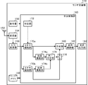
- FIG. 2 is a functional block diagram illustrating a schematic configuration of the radio receiver 110.
- FIG. 3 illustrates a reception unit 154, an A / D conversion unit 156, a mixer function unit 170, a specifying unit 172, and a detection function unit 174. It is the functional block diagram which showed the specific structure of these.
- the signal flow is indicated by solid arrows, and the control flow is indicated by broken arrows.
- the radio receiver 110 includes an operation unit 150, one antenna 152, one reception unit 154, one A / D conversion unit 156, a memory 158, and a central control unit 160. And an audio output unit 162.
- the operation unit 150 includes operation keys, a cross key, a joystick, a jog dial, a touch panel, and the like, and accepts user operation inputs.
- the antenna 152 receives an RF signal in a wide frequency band including RF signals of a plurality of carrier frequencies for terrestrial radio broadcasting, and converts the RF signal into a signal that can be processed by the receiving unit 154.
- the receiving unit 154 includes a first amplifier 154a that amplifies the RF signal, a band-pass filter (BPF) 154b that narrows the bandwidth of the RF signal, and a second amplifier 154c. And receiving an RF signal in a predetermined frequency band (for example, 87.5 MHz to 108.0 MHz) including RF signals of a plurality of carrier frequencies broadcast by a plurality of radio broadcasting stations 102.
- the RF signal received by the reception unit 154 is output to the A / D conversion unit 156 described later.
- the A / D conversion unit 156 converts an RF signal in a predetermined frequency band received by the reception unit 154 into a digital RF signal (A / D conversion) at a time.
- the A / D conversion unit 156 assumes a sampling frequency of 40 MHz or higher, and can convert an RF signal having a bandwidth of 20 MHz or higher into a digital RF signal at a time. Therefore, the A / D conversion unit 156 can convert an RF signal of 87.5 MHz to 108.0 MHz, which is a frequency band of a carrier wave of terrestrial radio broadcasting used in Europe, into a digital RF signal at a time, for example. It becomes possible.
- the memory 158 includes a RAM (Random Access Memory), a flash memory, an HDD (Hard Disk Drive), and the like, and holds various information necessary for processing of each functional unit of the central control unit 160.
- RAM Random Access Memory
- flash memory a flash memory
- HDD Hard Disk Drive
- the mixer function unit 170 (shown by 170a and 170b) includes a mixer 184a, an oscillator (local oscillator: Local Oscillator) 184b, and a low pass filter (LPF: Low Pass Filter) 184c.
- the digital RF signal converted by the A / D converter 156 is converted to an intermediate frequency (IF).
- IF intermediate frequency
- the mixer function The unit 170a converts the IF signal corresponding to the RF signal of the carrier frequency according to the operation input to the operation unit 150 by the user. More specifically, when the user sets the carrier frequency of the radio broadcast station 102 through the operation unit 150, the operation unit 150 transmits the set frequency to the mixer function unit 170a. Then, the mixer function unit 170a converts the digital RF signal into an IF signal corresponding to the RF signal having the transmitted frequency as a carrier wave.
- the mixer function unit 170b sequentially extracts digital RF signals, for example, every 50 kHz in the 87.5 MHz to 108.0 MHz band, and converts a digital RF signal having a signal strength equal to or greater than a predetermined threshold into an IF signal.
- the mixer 184a can convert digital RF signals having different carrier frequencies into IF signals having the same frequency (for example, 1 MHz).
- the central control unit 160 of the present embodiment is configured to include, for example, two mixer function units 170
- the mixer function unit 170b changes the oscillation frequency of the signal output from the oscillator 184b to the mixer 184a. All digital RF signals having a carrier frequency included in the bandwidth of 87.5 MHz to 108.0 MHz are converted into IF signals.
- the present invention is not limited to this, and the central control unit 160 includes as many mixer function units 170 as the number of carrier waves of the radio broadcast station 102 (for example, 400), and the frequency of the oscillator 184b of each mixer function unit 170 is fixed. Good.
- one mixer function unit 170 converts the IF signal corresponding to the RF signal of one carrier frequency according to the operation input to the operation unit 150 by the user.
- the other mixer function unit 170 converts the digital RF signal included in the bandwidth obtained by dividing the bandwidth of 87.5 MHz to 108.0 MHz by the number of other mixer function units 170 into an IF signal.
- the oscillator 184b of each mixer function unit 170 may change the oscillation frequency.
- the specifying unit 172 is an arbitrary mixer function unit that converts an IF signal corresponding to an RF signal having a receivable carrier frequency in accordance with an operation input by the user through the operation unit 150 among the plurality of mixer function units 170. 170 (here, the mixer function unit 170a) is specified.
- a detection function unit 174 (indicated by 174a and 174b in the figure) is provided for each mixer function unit 170 and detects a plurality of IF signals.
- the identity determination unit 176 determines whether the program content of the IF signal converted by the mixer function unit 170a specified by the specification unit 172 is the same as the program content of the IF signal converted by the other mixer function unit 170b. To determine. In the present embodiment, the same determination unit 176 determines whether the IF signal program content converted by the mixer function unit 170a and the mixer function unit 170b depend on whether or not the waveforms of the detected IF signals in a predetermined time range are substantially the same. It is determined whether or not the program content of one IF signal sequentially extracted from the plurality of IF signals converted by is identical.
- the same determination unit 176 detects one IF signal sequentially extracted from the IF signal converted by the mixer function unit 170a and the plurality of IF signals converted by the mixer function unit 170b, detected in a predetermined time range.
- the mean square error of the waveform is smaller than a predetermined value, it is determined that the error is the same, or from the IF signal converted by the mixer function unit 170a detected in the predetermined time range and the plurality of IF signals converted by the mixer function unit 170b
- the correlation value of the waveform of one IF signal extracted sequentially becomes equal to or greater than a predetermined value, it is determined that they are the same.
- FIG. 4 is an explanatory diagram for explaining the processing of the same determination unit 176.
- the identity determination unit 176 squares the waveform of the IF signal converted by the mixer function unit 170a shown in FIG. 4A and the waveform of the IF signal converted by the mixer function unit 170b shown in FIG. 4B. An average error is calculated, and when the mean square error is smaller than a predetermined value, these IF signals are determined to have the same program content.
- the same determination unit 176 squares the waveform of the IF signal converted by the mixer function unit 170a shown in FIG. 4A and the waveform of the IF signal converted by the mixer function unit 170b shown in FIG. 4C. An average error is calculated, and the mean square error is larger than a predetermined value, so that these IF signals are determined not to have the same program content.
- identity determining unit 176 determines whether the PI (Program Identification) code of the RDS information superimposed on the RF signal is the same. It can also be determined whether or not the program contents are the same.
- the PI code is an identifier indicating an individual program and a country where the program is broadcast. Therefore, if the PI code is the same, it can be determined that the program content is also the same.
- the same determination unit 176 compares the result of fast Fourier transform (FFT) with the IF signal as it is, determines whether the difference is within a predetermined range, and whether the program contents are the same. It may be determined.
- FFT fast Fourier transform
- the switch 178 is closed.
- the combining unit 180 generates a combined program signal by combining a plurality of IF signals determined to be the same.
- the audio control unit 182 detects (demodulates) the generated synthesized program signal and outputs it to the audio output unit 162.
- the audio output unit 162 is configured with a speaker or the like, and converts the detected synthesized program signal into audio in accordance with a control command from the audio control unit 182.
- an RF signal in a predetermined frequency band is once transmitted by one antenna 152 and one tuner (receiving unit 154 and A / D conversion unit 156). Because it can be converted into digital RF signals, it is easy to use the same IF signal as the selected IF signal among the generated IF signals without preparing multiple antennas or multiple tuners. And it becomes possible to extract rapidly.
- the combining unit 180 since the combining unit 180 generates a combined program signal by combining the IF signals determined to be the same by the same determining unit 176, the SNR (Signal of the same IF signal is compared with each IF signal before combining). to Noise Ratio) can be increased.
- a computer-readable flexible disk magneto-optical disk, ROM, EPROM, EEPROM, CD (Compact Disc), DVD (Digital Versatile Disc) on which a computer is made to function as the radio receiver 110 and recorded.
- a storage medium such as BD (Blu-ray Disc) is also provided.
- the program refers to data processing means described in an arbitrary language or description method.
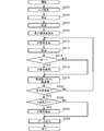
- FIG. 5 is a flowchart illustrating the processing flow of the radio reception method.
- the band of the RF signal converted by the A / D conversion unit 156 is 87.5 MHz to 108.0 MHz will be described as an example.
- the radio reception method operates as an interrupt process according to a 40 MHz interrupt signal.
- the A / D conversion unit 156 of the radio receiver 110 converts an RF signal in a predetermined frequency band received by the reception unit 154 into a digital RF signal at a time (S202).
- the mixer function unit 170a converts the digital RF signal converted in the A / D conversion step S202 into an IF signal corresponding to the receivable carrier frequency RF signal according to the operation input through the operation unit 150 by the user.
- the identifying unit 172 identifies the mixer function unit 170a that is converting the IF signal corresponding to the RF signal of the carrier frequency according to the user's operation input from among the plurality of mixer function units 170 (S204).
- the detection function unit 174a detects the IF signal converted by the mixer function unit 170a specified in the specifying step S204 (S206).
- the same determination unit 176 detects the IF signal detected in the detection step S206 (the IF signal converted by the mixer function unit 170a specified by the specifying unit 172) and the IF signal detected in the detection step S212 (the mixer function unit 170b It is determined whether or not the converted IF signal is the same (S214).
- central controller 160 stores the IF signal memory. Without performing the recording to 158, the processing after the frequency changing step S218 is performed. In this way, it is possible to confirm the presence or absence of an IF signal having the same program content as the IF signal converted by the mixer function unit 170a for every 50 kHz which is the carrier bandwidth of the radio broadcast station 102.
- the central control unit 160 stores the IF signal in the memory 158. It is determined whether or not it is held (S222), and if held (YES in S222), the synthesizing unit 180 synthesizes all IF signals held in the memory 158 in the holding step S216 and combines them.
- the signal is generated (S224), and the audio control unit 182 detects the synthesized program signal and outputs it to the audio output unit 162 (S226).
- the voice control unit 182 In the memory determination step S222, if the IF signal is not held in the memory 158 (NO in S222), the voice control unit 182 outputs the IF signal detected in the detection step S206 to the voice output unit 162 (S226).
- the RF signal of the carrier frequency of one or a plurality of radio broadcast stations 102 is converted into one antenna 152 and one tuner (reception unit 154 and A / D conversion unit). 156), it is possible to easily perform frequency diversity using the technology that can be acquired at once.
- each step of the radio reception method of the present specification does not necessarily have to be processed in time series in the order described in the flowchart, and may include processing in parallel or by a subroutine.
- the present invention can be used for a radio receiver, a radio reception method, and a program.
Landscapes
- Engineering & Computer Science (AREA)
- Signal Processing (AREA)
- Computer Networks & Wireless Communication (AREA)
- Radio Transmission System (AREA)
- Circuits Of Receivers In General (AREA)
Abstract
【課題】容易に周波数ダイバシティを行うことが可能となる。 【解決手段】ラジオ受信機110は、A/D変換部156が、1の受信部154が受信した所定の周波数帯域のRF信号を一度にデジタルRF信号に変換し、複数のミキサ機能部170が、デジタルRF信号を、搬送周波数の異なるRF信号に対応するIF信号にそれぞれ変換し、同一判定部176が、特定部172によって、ユーザの操作入力に応じた搬送周波数のRF信号に対応するIF信号に変換していると特定されたミキサ機能部170aが変換した1のIF信号の番組内容と、他のミキサ機能部170bが変換したIF信号の番組内容が同一であるか否か判定し、合成部180が、同一と判定された1または複数のIF信号とを合成して合成番組信号を生成し、合成番組信号を音声出力部へ出力させる。
Description
本発明は、ラジオ受信機、ラジオ受信方法およびプログラムに関する。
無線通信において、通信品質の向上を図るためにダイバシティ技術が利用されている。ダイバシティ技術には、例えば、受信側で複数のアンテナの位置を異ならせて配置し、受信状態が最も良いアンテナを選択して受信を行うアンテナダイバシティや、送信側で、異なる複数の搬送波で同一のデータ信号を送信し、受信側において、受信状態が最も良い搬送波を選択したり、複数の搬送波のデータ信号を合成する周波数ダイバシティがある。
アンテナダイバシティを利用した技術として、例えば、1つのアンテナを通じて、2つの受信部(チューナ)でそれぞれ受信したRF信号を復調し、得られた2つの映像データを合成して表示する受信装置において、2つの受信部において好適な受信状態を得られるようにアンテナの向きを制御する技術が開示されている(例えば、特許文献1)。
また、周波数ダイバシティを利用した技術として、例えば、複数のアンテナごとに設けられたチューナでそれぞれ受信した、搬送波の周波数が異なる受信信号を合成するデジタルデータ受信機が開示されている(例えば、特許文献2)。
ところで、近年、1つのアンテナを介して、20MHz以上の帯域幅のRF信号を受信し、受信した20MHz以上の帯域幅のRF信号を一度にA/D変換できる技術(Wide Band RF 技術)が開発されている。この技術を利用したラジオ受信機では、1つのアンテナおよび1つのチューナで、1または複数のラジオ放送局が放送する、20MHzの帯域幅に含まれる複数の搬送周波数(搬送波の周波数)のRF信号を一度に復調することができる。
そこで本発明は、1または複数のラジオ放送局の搬送周波数のRF信号を1つのアンテナおよび1つのチューナで一度に取得できる技術を利用して周波数ダイバシティを行うことが可能な、ラジオ受信機、ラジオ受信方法およびプログラムを提供することを目的としている。
上記課題を解決するために、本発明のラジオ受信機は、所定の周波数帯域のRF信号を受信する1の受信部と、受信部が受信した所定の周波数帯域のRF信号をデジタルRF信号に変換する1のA/D変換部と、デジタルRF信号を、搬送周波数の異なるRF信号に対応するIF信号にそれぞれ変換する複数のミキサ機能部と、複数のミキサ機能部のうち、ユーザの操作入力に応じた搬送周波数のRF信号に対応するIF信号に変換しているミキサ機能部を特定する特定部と、特定されたミキサ機能部で変換されたIF信号の番組内容と、他のミキサ機能部で変換されたIF信号の番組内容とが同一であるか否か判定する同一判定部と、特定されたミキサ機能部で変換されたIF信号と、同一判定部によって同一と判定されたIF信号とを合成して合成番組信号を生成する合成部と、合成番組信号を音声出力部へ出力させる音声制御部とを備えることを特徴とする。
上記ラジオ受信機は、ミキサ機能部で変換された複数のIF信号を検波する検波機能部と、をさらに備え、同一判定部は、検波されたIF信号によって番組内容が同一であるか否かを判定してもよい。
上記課題を解決するために、本発明のラジオ受信方法は、所定の周波数帯域のRF信号を受信し、受信した所定の周波数帯域のRF信号をデジタルRF信号に変換し、複数のミキサ機能部において、デジタルRF信号を、搬送周波数の異なるRF信号に対応するIF信号にそれぞれ変換し、複数のミキサ機能部のうち、ユーザの操作入力に応じた搬送周波数のRF信号に対応するIF信号に変換しているミキサ機能部を特定し、特定したミキサ機能部で変換したIF信号の番組内容と、他のミキサ機能部で変換したIF信号の番組内容とが同一であるか否か判定し、特定したミキサ機能部で変換したIF信号と、同一と判定したIF信号とを合成して合成番組信号を生成し、合成番組信号を音声出力部へ出力させることを特徴とする。
上記課題を解決するために、本発明のプログラムは、所定の周波数帯域のRF信号を受信するラジオ受信機に搭載されたコンピュータを、受信部が受信した所定の周波数帯域のRF信号をデジタルRF信号に変換する1のA/D変換部と、デジタルRF信号を、搬送周波数の異なるRF信号に対応するIF信号にそれぞれ変換する複数のミキサ機能部と、複数のミキサ機能部のうち、ユーザの操作入力に応じた搬送周波数のRF信号に対応するIF信号に変換しているミキサ機能部を特定する特定部と、特定されたミキサ機能部で変換されたIF信号の番組内容と、他のミキサ機能部で変換されたIF信号の番組内容とが同一であるか否か判定する同一判定部と、特定されたミキサ機能部で変換されたIF信号と、同一判定部によって同一と判定されたIF信号とを合成して合成番組信号を生成する合成部と、合成番組信号を音声出力部へ出力させる音声制御部として機能させることを特徴とする。
上述したラジオ受信機の技術的思想に基づく構成要素やその説明は、当該ラジオ受信方法およびプログラムにも適用可能である。
本発明によれば、1または複数のラジオ放送局の搬送周波数のRF信号を1つのアンテナおよび1つのチューナで一度に取得できる技術を利用して周波数ダイバシティを行うことが可能となる。
以下に添付図面を参照しながら、本発明の好適な実施形態について詳細に説明する。かかる実施形態に示す寸法、材料、その他具体的な数値などは、発明の理解を容易とするための例示にすぎず、特に断る場合を除き、本発明を限定するものではない。なお、本明細書及び図面において、実質的に同一の機能、構成を有する要素については、同一の符号を付することにより重複説明を省略し、また本発明に直接関係のない要素は図示を省略する。
(ラジオ受信システム100)
図1は、ラジオ受信システム100の概略的な接続関係を示した説明図である。ラジオ受信システム100は、複数のラジオ放送局102と、複数の放送塔104と、ラジオ受信機110とを含んで構成される。
図1は、ラジオ受信システム100の概略的な接続関係を示した説明図である。ラジオ受信システム100は、複数のラジオ放送局102と、複数の放送塔104と、ラジオ受信機110とを含んで構成される。
ラジオ放送局102は、地上波ラジオ放送、例えば、アナログ方式のRF信号や、デジタル方式のRF信号、アナログ方式とデジタル方式とを同時に提供するハイブリッド方式のRF信号を提供する。また、ラジオ放送局102は、RF信号において、オーディオ信号にデータ信号を重畳することができる。例えば、後述する例において、ラジオ放送局102は、デジタル方式のRF信号にデータ信号として、欧州におけるRDS(Radio Data System)情報を重畳している。
放送塔104は、位置を異にして複数配置され、複数のラジオ放送局102が放送する複数のRF信号を発信する。
ラジオ受信機110は、複数のラジオ放送局102がそれぞれ放送する複数のRF信号を、放送塔104を介して受信する。そして、ラジオ受信機110は、受信したRF信号をIF(Intermediate Frequency:中間周波数)信号に変換し、そのIF信号を復調した番組データに含まれるオーディオデータをスピーカ等で構成された音声出力部に出力させる。
ここで、ラジオ受信機110が車両等の移動体106に搭載される場合、ラジオ受信機110の位置によって、ラジオ受信機110は、必要な受信電波強度を確保できない場合がある。そこで、欧州における地上波ラジオ放送において、ラジオ放送局102は、複数の周波数の搬送波で同一の番組を放送している。
一方、1つのアンテナを介して、20MHz以上の帯域幅のRF信号を受信し、受信した20MHz以上の帯域幅のRF信号を一度にデジタルRF信号に変換できる技術(Wide Band RF技術)が開発されている。この技術を利用したラジオ受信機110では、1または複数のラジオ放送局102が放送する複数のRF信号を1つのアンテナおよび1つのチューナで一度に取得できる。
そこで、本実施形態では、上述した、1または複数のラジオ放送局102が放送する複数の搬送周波数(搬送波の周波数)のRF信号を1つのアンテナおよび1つのチューナで一度に取得できる技術を利用したラジオ受信機110において、周波数ダイバシティが可能なラジオ受信機110を提供することを目的とする。以下、ラジオ受信機110の具体的な構成について説明し、続いてラジオ受信機110を利用したラジオ受信方法について詳述する。
(ラジオ受信機110)
図2は、ラジオ受信機110の概略的な構成を示した機能ブロック図であり、図3は、受信部154、A/D変換部156、ミキサ機能部170、特定部172、検波機能部174の具体的な構成を示した機能ブロック図である。図2および図3中、信号の流れを実線の矢印で示し、制御の流れを破線の矢印で示す。
図2は、ラジオ受信機110の概略的な構成を示した機能ブロック図であり、図3は、受信部154、A/D変換部156、ミキサ機能部170、特定部172、検波機能部174の具体的な構成を示した機能ブロック図である。図2および図3中、信号の流れを実線の矢印で示し、制御の流れを破線の矢印で示す。
図2に示すように、ラジオ受信機110は、操作部150と、1のアンテナ152と、1の受信部154と、1のA/D変換部156と、メモリ158と、中央制御部160と、音声出力部162とを含んで構成される。
操作部150は、操作キー、十字キー、ジョイスティック、ジョグダイヤル、タッチパネル等で構成され、ユーザの操作入力を受け付ける。アンテナ152は、地上波ラジオ放送の複数の搬送周波数のRF信号を含む広周波数帯域のRF信号を受信し、受信部154で処理可能な信号に変換する。
図3に示すように、受信部154は、RF信号を増幅する第1増幅器154aと、RF信号の帯域幅を絞るバンドパスフィルタ(Band Pass Filter:BPF)154bと、第2増幅器154cとを含んで構成され、複数のラジオ放送局102が放送する複数の搬送周波数のRF信号を含む所定の周波数帯域(例えば、87.5MHz~108.0MHz)のRF信号を受信する。受信部154が受信したRF信号は、後述するA/D変換部156に出力される。
A/D変換部156は、受信部154が受信した所定の周波数帯域のRF信号を一度にデジタルRF信号に変換(A/D変換)する。
本実施形態において、A/D変換部156は、サンプリング周波数が40MHz以上のものを想定しており、20MHz以上の帯域幅のRF信号を一度にデジタルRF信号に変換できる。したがって、A/D変換部156は、例えば、欧州で利用されている地上波ラジオ放送の搬送波の周波数帯域である87.5MHz~108.0MHzのRF信号を一度にデジタルRF信号に変換することが可能となる。
メモリ158は、RAM(Random Access Memory)、フラッシュメモリ、HDD(Hard Disk Drive)等で構成され、中央制御部160の各機能部の処理に必要な各種情報を保持する。
中央制御部160は、中央処理装置(DSPやCPU)、プログラム等が格納されたROM、ワークエリアとしてのRAM等を含む半導体集積回路により、ラジオ受信機110全体を管理および制御する。また、本実施形態において、中央制御部160は、複数のミキサ機能部170、特定部172、検波機能部174、同一判定部176、スイッチ178、合成部180、音声制御部182としても機能する。
ミキサ機能部170(図中、170a、170bで示す)は、図3に示すように、ミキサ184aと、発振器(局部発振器:Local Oscillator)184bと、低域通過フィルタ(LPF:Low Pass Filter)184cとを含んで構成され、A/D変換部156が変換したデジタルRF信号を中間周波数(Intermediate Frequency:IF)に変換する。ここでは、中央制御部160がミキサ機能部170を2つ備える構成を例に挙げて説明する。
図3を用いて具体的に説明すると、例えば、A/D変換部156が変換したデジタルRF信号の帯域が87.5MHz~108.0MHzであり、ミキサ機能部170が2つある場合、ミキサ機能部170aは、ユーザによる操作部150への操作入力に応じた搬送周波数のRF信号に対応するIF信号に変換する。具体的に説明すると、操作部150を通じて、ユーザがラジオ放送局102の搬送周波数を設定すると、操作部150は、設定された周波数をミキサ機能部170aに伝達する。そうすると、ミキサ機能部170aは、デジタルRF信号を、伝達された周波数を搬送波とするRF信号に対応するIF信号に変換する。ミキサ機能部170bは、87.5MHz~108.0MHz帯域において、例えば、50kHzごとにデジタルRF信号を順次抽出し、所定の閾値以上の信号強度のデジタルRF信号をIF信号に変換する。
ここで、発振器184bがミキサ184aに出力する信号の発振周波数を変更することによって、ミキサ184aは、搬送周波数の異なるデジタルRF信号を同一の周波数(例えば、1MHz)のIF信号にすることができる。
なお、本実施形態の中央制御部160は、ミキサ機能部170を例えば2つ備える構成であるため、ミキサ機能部170bは、発振器184bがミキサ184aに出力する信号の発振周波数を変更することにより、87.5MHz~108.0MHzの帯域幅に含まれる搬送周波数のデジタルRF信号をすべてIF信号に変換することになる。しかし、これに限定されず、中央制御部160が、ラジオ放送局102の搬送波の数(例えば、400)だけミキサ機能部170を備え、各ミキサ機能部170の発振器184bの周波数を固定してもよい。また、中央制御部160がミキサ機能部170を3以上備える場合、1のミキサ機能部170が、ユーザによる操作部150への操作入力に応じた1の搬送周波数のRF信号に対応するIF信号に変換し、他のミキサ機能部170は、87.5MHz~108.0MHzの帯域幅を他のミキサ機能部170の数で分割した帯域幅に含まれるデジタルRF信号をそれぞれIF信号に変換できるように、各ミキサ機能部170の発振器184bが発振周波数を変更してもよい。
特定部172は、複数のミキサ機能部170のうち、ユーザによる操作部150を通じた操作入力に応じた、受信可能な搬送周波数のRF信号に対応するIF信号に変換している任意のミキサ機能部170(ここでは、ミキサ機能部170a)を特定する。
検波機能部174(図中、174a、174bで示す)は、ミキサ機能部170ごとに設けられ、複数のIF信号を検波する。
同一判定部176は、特定部172が特定したミキサ機能部170aで変換されたIF信号の番組内容と、他のミキサ機能部170bで変換された、IF信号の番組内容とが同一であるか否か判定する。本実施形態において同一判定部176は、所定の時間範囲における検波されたIF信号の波形が略同一であるか否かで、ミキサ機能部170aが変換したIF信号の番組内容と、ミキサ機能部170bが変換した複数のIF信号から順次抽出された1のIF信号の番組内容が同一であるか否か判定する。具体的に同一判定部176は、所定の時間範囲における検波された、ミキサ機能部170aが変換したIF信号と、ミキサ機能部170bが変換した複数のIF信号から順次抽出された1のIF信号の波形の二乗平均誤差が所定の値より小さくなると同一と判断したり、所定の時間範囲における検波された、ミキサ機能部170aが変換したIF信号と、ミキサ機能部170bが変換した複数のIF信号から順次抽出された1のIF信号の波形の相関値が所定の値以上となると同一と判断したりする。
図4は、同一判定部176の処理を説明するための説明図である。例えば、同一判定部176は、図4(a)に示す、ミキサ機能部170aが変換したIF信号の波形と、図4(b)に示す、ミキサ機能部170bが変換したIF信号の波形の二乗平均誤差を算出し、その二乗平均誤差が所定の値より小さいことにより、これらのIF信号は、番組内容が同一であると判定する。また、同一判定部176は、図4(a)に示す、ミキサ機能部170aが変換したIF信号の波形と、図4(c)に示す、ミキサ機能部170bが変換したIF信号の波形の二乗平均誤差を算出し、その二乗平均誤差が所定の値より大きいことにより、これらのIF信号は、番組内容が同一でないと判定する。
なお、受信部154が欧州の地上波ラジオ放送波のRF信号を受信する場合、同一判定部176は、RF信号に重畳されたRDS情報のPI(Program Identification)コードが同一であるか否かで、番組内容が同一であるか否かを判定することもできる。PIコードは、個々の番組とその番組が放送されている国を示す識別子である。したがって、PIコードが等しいと番組内容も等しいと判定できる。
また、同一判定部176は、IF信号を、そのまま、高速フーリエ変換(Fast Fourier Transform:FFT)した結果を比較し、その差分が所定の範囲内であるかを判定し、番組内容が同一か否かを判定してもよい。
そして、同一判定部176は、番組内容が同一であると判定すると、スイッチ178を閉にする。
合成部180は、同一と判定された複数のIF信号を合成して合成番組信号を生成する。音声制御部182は、生成された合成番組信号を検波(復調)して音声出力部162へ出力させる。
音声出力部162は、スピーカ等で構成され、音声制御部182の制御指令に応じて、検波された合成番組信号を音声に変換する。
以上説明したように、本実施形態にかかるラジオ受信機110によれば、1つのアンテナ152および1つのチューナ(受信部154およびA/D変換部156)で、所定の周波数帯域のRF信号を一度にデジタルRF信号に変換できるため、複数のアンテナを用意したり、複数のチューナを用意することなく、生成された複数のIF信号のうち、選局されているIF信号と同一のIF信号を容易かつ迅速に抽出することが可能となる。
また、合成部180が、同一判定部176が同一であると判定したIF信号を合成して合成番組信号を生成するため、合成前の各IF信号に比べて、同一のIF信号のSNR(Signal to Noise Ratio)を上げることが可能となる。
また、コンピュータを、ラジオ受信機110として機能させるプログラムや当該プログラムを記録した、コンピュータで読み取り可能なフレキシブルディスク、光磁気ディスク、ROM、EPROM、EEPROM、CD(Compact Disc)、DVD(Digital Versatile Disc)、BD(Blu-ray Disc)等の記憶媒体も提供される。ここで、プログラムは、任意の言語や記述方法にて記述されたデータ処理手段をいう。
(ラジオ受信方法)
図5は、ラジオ受信方法の処理の流れを説明したフローチャートである。ここでは、A/D変換部156が変換するRF信号の帯域が87.5MHz~108.0MHzである場合を例に挙げて説明する。本実施形態において、ラジオ受信方法は、40MHzの割り込み信号に応じた、割り込み処理として動作する。図5に示すように、ラジオ受信機110のA/D変換部156は、受信部154が受信した所定の周波数帯域のRF信号を一度にデジタルRF信号に変換する(S202)。
図5は、ラジオ受信方法の処理の流れを説明したフローチャートである。ここでは、A/D変換部156が変換するRF信号の帯域が87.5MHz~108.0MHzである場合を例に挙げて説明する。本実施形態において、ラジオ受信方法は、40MHzの割り込み信号に応じた、割り込み処理として動作する。図5に示すように、ラジオ受信機110のA/D変換部156は、受信部154が受信した所定の周波数帯域のRF信号を一度にデジタルRF信号に変換する(S202)。
そして、ミキサ機能部170aは、A/D変換ステップS202で変換されたデジタルRF信号を、ユーザによる操作部150を通じた操作入力に応じた、受信可能な搬送周波数のRF信号に対応するIF信号に変換し、特定部172は、複数のミキサ機能部170のうち、ユーザの操作入力に応じた搬送周波数のRF信号に対応するIF信号に変換しているミキサ機能部170aを特定する(S204)。検波機能部174aは、特定ステップS204で特定されたミキサ機能部170aが変換したIF信号を検波する(S206)。
一方、ミキサ機能部170bは、IF信号への変換を試みるデジタルRF信号の搬送周波数として、RF信号の帯域の最小周波数である87.5MHzを設定し(S208)、87.5MHzのデジタルRF信号を抽出してIF信号に変換する(S210)。検波機能部174bは、IF変換ステップS210で変換されたIF信号を検波する(S212)。
そして同一判定部176は、検波ステップS206で検波されたIF信号(特定部172が特定したミキサ機能部170aが変換したIF信号)と、検波ステップS212で検波されたIF信号(ミキサ機能部170bが変換したIF信号)とが同一であるか否かを判定する(S214)。
検波ステップS212で検波されたIF信号の番組内容が、検波ステップS206で検波されたIF信号の番組内容と同一であると判定されると(S214におけるYES)、中央制御部160は、IF変換ステップS210で変換されたIF信号をメモリ158に保持させる(S216)。そして、ミキサ機能部170bは、IF信号への変換を試みるデジタルRF信号の搬送周波数に例えば50kHzを加算し(S218)、IF信号の変換元のデジタルRF信号の搬送周波数が、RF信号の帯域の最大周波数である108.0MHzであるか否かを判定し(S220)、最大周波数でなければ(S220におけるNO)、IF変換ステップS210以降の処理を遂行する。
検波ステップS212で検波されたIF信号の番組内容が、検波ステップS206で検波されたIF信号の番組内容と同一でないと判定されると(S214におけるNO)、中央制御部160は、IF信号のメモリ158への記録を行わず、周波数変更ステップS218以降の処理を遂行する。こうして、ラジオ放送局102の搬送波の帯域幅である50kHz毎に、ミキサ機能部170aが変換したIF信号と同一の番組内容のIF信号の有無を確認することができる。
IF信号の変換元のデジタルRF信号の搬送周波数が、RF信号の帯域の最大周波数であれば(S220におけるYES)、すなわち受信部154が受信したRF信号の帯域幅に含まれるすべての搬送周波数のRF信号に対応するIF信号の番組内容と、検波ステップS206で検波されたIF信号の番組内容とが同一であるか否かの判定を終了すると、中央制御部160は、メモリ158にIF信号が保持されているか否かを判定し(S222)、保持されていれば(S222におけるYES)、合成部180は、保持ステップS216において、メモリ158に保持させたすべてのIF信号を合成して合成番組信号を生成し(S224)、音声制御部182は、合成番組信号を検波して音声出力部162に出力させる(S226)。メモリ判定ステップS222において、メモリ158にIF信号が保持されていなければ(S222におけるNO)、音声制御部182は、検波ステップS206で検波されたIF信号を音声出力部162へ出力させる(S226)。
以上説明したように、本実施形態にかかるラジオ受信方法においても、1または複数のラジオ放送局102の搬送周波数のRF信号を1つのアンテナ152および1つのチューナ(受信部154およびA/D変換部156)で一度に取得できる技術を利用して、容易に周波数ダイバシティを行うことが可能となる。
以上、添付図面を参照しながら本発明の好適な実施形態について説明したが、本発明はかかる実施形態に限定されないことは言うまでもない。当業者であれば、特許請求の範囲に記載された範疇において、各種の変更例または修正例に想到し得ることは明らかであり、それらについても当然に本発明の技術的範囲に属するものと了解される。
なお、本明細書のラジオ受信方法の各工程は、必ずしもフローチャートとして記載された順序に沿って時系列に処理する必要はなく、並列的あるいはサブルーチンによる処理を含んでもよい。
本発明は、ラジオ受信機、ラジオ受信方法およびプログラムに利用することができる。
110 …ラジオ受信機
150 …操作部
152 …アンテナ
154 …受信部
156 …A/D変換部
158 …メモリ
160 …中央制御部
162 …音声出力部
170 …ミキサ機能部
172 …特定部
174 …検波機能部
176 …同一判定部
178 …スイッチ
180 …合成部
182 …音声制御部
150 …操作部
152 …アンテナ
154 …受信部
156 …A/D変換部
158 …メモリ
160 …中央制御部
162 …音声出力部
170 …ミキサ機能部
172 …特定部
174 …検波機能部
176 …同一判定部
178 …スイッチ
180 …合成部
182 …音声制御部
Claims (4)
- 所定の周波数帯域のRF信号を受信する1の受信部と、
前記受信部が受信した前記所定の周波数帯域のRF信号をデジタルRF信号に変換する1のA/D変換部と、
前記デジタルRF信号を、搬送周波数の異なるRF信号に対応するIF信号にそれぞれ変換する複数のミキサ機能部と、
前記複数のミキサ機能部のうち、ユーザの操作入力に応じた搬送周波数のRF信号に対応するIF信号に変換しているミキサ機能部を特定する特定部と、
特定された前記ミキサ機能部で変換されたIF信号の番組内容と、他のミキサ機能部で変換されたIF信号の番組内容とが同一であるか否か判定する同一判定部と、
前記特定されたミキサ機能部で変換されたIF信号と、前記同一判定部によって同一と判定されたIF信号とを合成して合成番組信号を生成する合成部と、
前記合成番組信号を音声出力部へ出力させる音声制御部と、
を備えることを特徴とするラジオ受信機。 - 前記ミキサ機能部で変換された前記複数のIF信号を検波する検波機能部と、
をさらに備え、
前記同一判定部は、検波されたIF信号によって番組内容が同一であるか否かを判定することを特徴とする請求項1に記載のラジオ受信機。 - 所定の周波数帯域のRF信号を受信し、
受信した前記所定の周波数帯域のRF信号をデジタルRF信号に変換し、
複数のミキサ機能部において、前記デジタルRF信号を、搬送周波数の異なるRF信号に対応するIF信号にそれぞれ変換し、
前記複数のミキサ機能部のうち、ユーザの操作入力に応じた搬送周波数のRF信号に対応するIF信号に変換しているミキサ機能部を特定し、
特定した前記ミキサ機能部で変換したIF信号の番組内容と、他のミキサ機能部で変換したIF信号の番組内容とが同一であるか否か判定し、
前記特定したミキサ機能部で変換したIF信号と、同一と判定した前記IF信号とを合成して合成番組信号を生成し、
前記合成番組信号を音声出力部へ出力させることを特徴とするラジオ受信方法。 - 所定の周波数帯域のRF信号を受信するラジオ受信機に搭載されたコンピュータを、
前記受信部が受信した前記所定の周波数帯域のRF信号をデジタルRF信号に変換する1のA/D変換部と、
前記デジタルRF信号を、搬送周波数の異なるRF信号に対応するIF信号にそれぞれ変換する複数のミキサ機能部と、
前記複数のミキサ機能部のうち、ユーザの操作入力に応じた搬送周波数のRF信号に対応するIF信号に変換しているミキサ機能部を特定する特定部と、
特定された前記ミキサ機能部で変換されたIF信号の番組内容と、他のミキサ機能部で変換されたIF信号の番組内容とが同一であるか否か判定する同一判定部と、
前記特定されたミキサ機能部で変換されたIF信号と、前記同一判定部によって同一と判定されたIF信号とを合成して合成番組信号を生成する合成部と、
前記合成番組信号を音声出力部へ出力させる音声制御部と
して機能させるためのプログラム。
Applications Claiming Priority (2)
| Application Number | Priority Date | Filing Date | Title |
|---|---|---|---|
| JP2010-284692 | 2010-12-21 | ||
| JP2010284692A JP2012134738A (ja) | 2010-12-21 | 2010-12-21 | ラジオ受信機、ラジオ受信方法およびプログラム |
Publications (1)
| Publication Number | Publication Date |
|---|---|
| WO2012086431A1 true WO2012086431A1 (ja) | 2012-06-28 |
Family
ID=46313711
Family Applications (1)
| Application Number | Title | Priority Date | Filing Date |
|---|---|---|---|
| PCT/JP2011/078507 Ceased WO2012086431A1 (ja) | 2010-12-21 | 2011-12-09 | ラジオ受信機、ラジオ受信方法およびプログラム |
Country Status (2)
| Country | Link |
|---|---|
| JP (1) | JP2012134738A (ja) |
| WO (1) | WO2012086431A1 (ja) |
Families Citing this family (1)
| Publication number | Priority date | Publication date | Assignee | Title |
|---|---|---|---|---|
| CN105245268B (zh) * | 2015-10-27 | 2018-04-13 | 安徽四创电子股份有限公司 | 基于双通道频率分集技术的信号处理器及其信号处理方法 |
Citations (5)
| Publication number | Priority date | Publication date | Assignee | Title |
|---|---|---|---|---|
| JPH07143020A (ja) * | 1993-11-15 | 1995-06-02 | Taisei Corp | 強制視聴装置 |
| JPH1127163A (ja) * | 1997-06-30 | 1999-01-29 | Clarion Co Ltd | 多重放送受信装置 |
| JP2000041020A (ja) * | 1998-07-23 | 2000-02-08 | Jisedai Digital Television Hoso System Kenkyusho:Kk | Ofdm方式の受信装置 |
| JP2001103024A (ja) * | 1999-09-29 | 2001-04-13 | Fujitsu Ltd | デジタル無線装置、デジタル無線通信システム、デジタル無線送信装置、デジタル無線通信方法 |
| JP2002033689A (ja) * | 2000-07-13 | 2002-01-31 | Gcomm Corp | 微弱電波通信装置 |
-
2010
- 2010-12-21 JP JP2010284692A patent/JP2012134738A/ja active Pending
-
2011
- 2011-12-09 WO PCT/JP2011/078507 patent/WO2012086431A1/ja not_active Ceased
Patent Citations (5)
| Publication number | Priority date | Publication date | Assignee | Title |
|---|---|---|---|---|
| JPH07143020A (ja) * | 1993-11-15 | 1995-06-02 | Taisei Corp | 強制視聴装置 |
| JPH1127163A (ja) * | 1997-06-30 | 1999-01-29 | Clarion Co Ltd | 多重放送受信装置 |
| JP2000041020A (ja) * | 1998-07-23 | 2000-02-08 | Jisedai Digital Television Hoso System Kenkyusho:Kk | Ofdm方式の受信装置 |
| JP2001103024A (ja) * | 1999-09-29 | 2001-04-13 | Fujitsu Ltd | デジタル無線装置、デジタル無線通信システム、デジタル無線送信装置、デジタル無線通信方法 |
| JP2002033689A (ja) * | 2000-07-13 | 2002-01-31 | Gcomm Corp | 微弱電波通信装置 |
Also Published As
| Publication number | Publication date |
|---|---|
| JP2012134738A (ja) | 2012-07-12 |
Similar Documents
| Publication | Publication Date | Title |
|---|---|---|
| US7343143B2 (en) | Radio receiver with operation state setting unit | |
| US8064857B2 (en) | Method and apparatus for co-channel interference detection in a radio | |
| JP2005159535A (ja) | 音声放送受信装置および受信方法 | |
| JP4614906B2 (ja) | 受信装置 | |
| WO2012086431A1 (ja) | ラジオ受信機、ラジオ受信方法およびプログラム | |
| JP2005333572A (ja) | 受信機 | |
| JP4159964B2 (ja) | オーディオ放送受信装置及び自動選局方法 | |
| JP2008017292A (ja) | ラジオ放送受信装置およびラジオ放送の自動選局装置 | |
| JP4401837B2 (ja) | 放送受信機及び受信切り替え方法 | |
| JP2011211585A (ja) | ラジオ受信機 | |
| JP2021136632A (ja) | 受信装置、及び受信方法 | |
| CN102648585A (zh) | 用于接收无线电发射的方法和系统 | |
| JP2012129671A (ja) | ラジオ受信機、ラジオ受信方法およびプログラム | |
| JP4800279B2 (ja) | 受信装置および受信方法 | |
| US6968164B2 (en) | Method of controlling filter bandwidth in a radio receiver for a duplicative broadcast signal | |
| JP2009141468A (ja) | 放送受信機、およびチャネルシーク方法 | |
| KR20150044347A (ko) | 디지털 오디오 방송 장치 및 그 방법 | |
| JP2005130058A (ja) | 受信装置及び受信装置のプリセット方法 | |
| JP6257894B2 (ja) | 放送受信装置及び放送受信方法 | |
| JP2009049605A (ja) | 受信装置、受信プログラム、受信方法および受信回路 | |
| JP2000041021A (ja) | 受信機 | |
| JP2013131955A (ja) | 受信装置および受信装置による未使用周波数検出方法 | |
| JP6144909B2 (ja) | 放送受信装置及び放送受信方法 | |
| JP2006109186A (ja) | アンテナダイバーシティ方式の受信機 | |
| JP2014204274A (ja) | 放送受信装置及び放送受信方法 |
Legal Events
| Date | Code | Title | Description |
|---|---|---|---|
| 121 | Ep: the epo has been informed by wipo that ep was designated in this application |
Ref document number: 11851458 Country of ref document: EP Kind code of ref document: A1 |
|
| NENP | Non-entry into the national phase |
Ref country code: DE |
|
| 122 | Ep: pct application non-entry in european phase |
Ref document number: 11851458 Country of ref document: EP Kind code of ref document: A1 |