WO2012081548A1 - 流体供給装置、レジスト現像装置およびモールド製造方法 - Google Patents
流体供給装置、レジスト現像装置およびモールド製造方法 Download PDFInfo
- Publication number
- WO2012081548A1 WO2012081548A1 PCT/JP2011/078692 JP2011078692W WO2012081548A1 WO 2012081548 A1 WO2012081548 A1 WO 2012081548A1 JP 2011078692 W JP2011078692 W JP 2011078692W WO 2012081548 A1 WO2012081548 A1 WO 2012081548A1
- Authority
- WO
- WIPO (PCT)
- Prior art keywords
- temperature
- medium
- substrate
- resist
- processed
- Prior art date
- Legal status (The legal status is an assumption and is not a legal conclusion. Google has not performed a legal analysis and makes no representation as to the accuracy of the status listed.)
- Ceased
Links
Images




Classifications
-
- H—ELECTRICITY
- H10—SEMICONDUCTOR DEVICES; ELECTRIC SOLID-STATE DEVICES NOT OTHERWISE PROVIDED FOR
- H10P—GENERIC PROCESSES OR APPARATUS FOR THE MANUFACTURE OR TREATMENT OF DEVICES COVERED BY CLASS H10
- H10P72/00—Handling or holding of wafers, substrates or devices during manufacture or treatment thereof
- H10P72/04—Apparatus for manufacture or treatment
- H10P72/0402—Apparatus for fluid treatment
- H10P72/0406—Apparatus for fluid treatment for cleaning followed by drying, rinsing, stripping, blasting or the like
- H10P72/0411—Apparatus for fluid treatment for cleaning followed by drying, rinsing, stripping, blasting or the like for wet cleaning or washing
- H10P72/0414—Apparatus for fluid treatment for cleaning followed by drying, rinsing, stripping, blasting or the like for wet cleaning or washing using mainly spraying means, e.g. nozzles
-
- B—PERFORMING OPERATIONS; TRANSPORTING
- B82—NANOTECHNOLOGY
- B82Y—SPECIFIC USES OR APPLICATIONS OF NANOSTRUCTURES; MEASUREMENT OR ANALYSIS OF NANOSTRUCTURES; MANUFACTURE OR TREATMENT OF NANOSTRUCTURES
- B82Y10/00—Nanotechnology for information processing, storage or transmission, e.g. quantum computing or single electron logic
-
- B—PERFORMING OPERATIONS; TRANSPORTING
- B82—NANOTECHNOLOGY
- B82Y—SPECIFIC USES OR APPLICATIONS OF NANOSTRUCTURES; MEASUREMENT OR ANALYSIS OF NANOSTRUCTURES; MANUFACTURE OR TREATMENT OF NANOSTRUCTURES
- B82Y40/00—Manufacture or treatment of nanostructures
-
- G—PHYSICS
- G03—PHOTOGRAPHY; CINEMATOGRAPHY; ANALOGOUS TECHNIQUES USING WAVES OTHER THAN OPTICAL WAVES; ELECTROGRAPHY; HOLOGRAPHY
- G03F—PHOTOMECHANICAL PRODUCTION OF TEXTURED OR PATTERNED SURFACES, e.g. FOR PRINTING, FOR PROCESSING OF SEMICONDUCTOR DEVICES; MATERIALS THEREFOR; ORIGINALS THEREFOR; APPARATUS SPECIALLY ADAPTED THEREFOR
- G03F7/00—Photomechanical, e.g. photolithographic, production of textured or patterned surfaces, e.g. printing surfaces; Materials therefor, e.g. comprising photoresists; Apparatus specially adapted therefor
- G03F7/26—Processing photosensitive materials; Apparatus therefor
- G03F7/30—Imagewise removal using liquid means
- G03F7/3021—Imagewise removal using liquid means from a wafer supported on a rotating chuck
-
- H—ELECTRICITY
- H10—SEMICONDUCTOR DEVICES; ELECTRIC SOLID-STATE DEVICES NOT OTHERWISE PROVIDED FOR
- H10P—GENERIC PROCESSES OR APPARATUS FOR THE MANUFACTURE OR TREATMENT OF DEVICES COVERED BY CLASS H10
- H10P72/00—Handling or holding of wafers, substrates or devices during manufacture or treatment thereof
- H10P72/04—Apparatus for manufacture or treatment
- H10P72/0402—Apparatus for fluid treatment
- H10P72/0418—Apparatus for fluid treatment for etching
- H10P72/0422—Apparatus for fluid treatment for etching for wet etching
- H10P72/0424—Apparatus for fluid treatment for etching for wet etching using mainly spraying means, e.g. nozzles
-
- G—PHYSICS
- G03—PHOTOGRAPHY; CINEMATOGRAPHY; ANALOGOUS TECHNIQUES USING WAVES OTHER THAN OPTICAL WAVES; ELECTROGRAPHY; HOLOGRAPHY
- G03F—PHOTOMECHANICAL PRODUCTION OF TEXTURED OR PATTERNED SURFACES, e.g. FOR PRINTING, FOR PROCESSING OF SEMICONDUCTOR DEVICES; MATERIALS THEREFOR; ORIGINALS THEREFOR; APPARATUS SPECIALLY ADAPTED THEREFOR
- G03F7/00—Photomechanical, e.g. photolithographic, production of textured or patterned surfaces, e.g. printing surfaces; Materials therefor, e.g. comprising photoresists; Apparatus specially adapted therefor
- G03F7/0002—Lithographic processes using patterning methods other than those involving the exposure to radiation, e.g. by stamping
Definitions
- the present invention relates to a fluid supply device, a resist developing device, and a mold manufacturing method.
- a resist developing device is known as an example of a liquid supply device used in the field of lithography (see, for example, Patent Document 1).
- the resist developing apparatus supplies and sprays a developer or a rinse solution to the resist layer that has undergone exposure or drawing (hereinafter also referred to as “exposure”), thereby dissolving and removing unnecessary portions of the resist layer and developing (hereinafter referred to as “ It is also an apparatus for forming a resist pattern.
- the solubility (speed) of the developer in the resist layer is lowered, and in particular, dissolution of the resist pattern portion (non-dissolved portion) is suppressed. .
- the difference in solubility (speed) in the developing solution between the dissolved portion and the non-dissolved portion becomes larger, the shape / quality of the resist pattern is improved, and the resolution is improved.
- the rinsing liquid is dissolved in the resist layer when rinsing is performed using a rinsing liquid that is adjusted and controlled to a temperature lower than normal temperature.
- normal temperature described in this specification refers to, for example, around 22.5 ° C., which is a general set temperature of a dust-free room (clean room) for semiconductor manufacturing.
- the accuracy of temperature control of the dust-free chamber is generally about the set value +/ ⁇ 0.1 ° C. to +/ ⁇ 1 ° C.
- the temperature of the developer used in the low temperature development method is, for example, less than 21.5 ° C.
- the temperature is within the temperature range where the developer does not freeze (temperature higher than the freezing point), and the temperature at which the solution temperature can be adjusted and controlled practically. Can be used.
- ⁇ 10 ° C., ⁇ 60 ° C. and the like described in Non-Patent Document 1 are selected, and the developer and the rinsing liquid are set to the temperatures.
- the temperature of the developer or further rinse solution (hereinafter also referred to as “developer”) is set to a temperature lower than the dew point temperature (hereinafter also referred to as “atmosphere dew point temperature”) determined from the temperature and humidity of the surrounding atmosphere.
- the substrate to be treated and its main surface are treated.
- the temperature of a certain resist pattern is also lower than the atmospheric dew point temperature.
- the resist layer is developed using a developer having a temperature lower than the atmospheric dew point
- the resist formed on the surface of the substrate after the development treatment that is, the resist formed by using some measure, is used. It is necessary to prevent condensation on the surface of the pattern.
- the main object of the present invention is to provide a fluid supply device, a resist developing device, and a mold manufacturing method capable of avoiding the occurrence of a failure caused by the failure, for example, the occurrence of a failure such as a fall of the resist pattern. .
- a first aspect of the present invention includes a holding unit that holds an object to be processed or a substrate including the object to be processed (hereinafter also referred to as “object to be processed”), A fluid supply unit for supplying and dispersing fluid to the object to be processed held by the holding unit; A dew condensation prevention medium supply unit that performs supply and dispersion of a dew condensation prevention medium for bringing the fluid into a state of being at a temperature higher than the atmosphere dew point temperature with respect to the object to be processed which is at a temperature lower than the atmosphere dew point temperature; It is provided with the fluid supply apparatus characterized by the above-mentioned.
- the dew condensation prevention medium is a fluid that does not dissolve and damage the workpiece.
- Stopping the supply and spraying of the dew condensation prevention medium, and then, during the drying process of the object to be processed, or after finishing the drying process, the object to be processed again toward the atmospheric dew point temperature or lower temperature A heat loss compensation medium supply unit that supplies and disperses a heat loss compensation medium that compensates for heat loss of the object to be treated in order to maintain the object at a temperature higher than the atmospheric dew point temperature. It is characterized by that.
- a fourth aspect of the present invention is a resist development apparatus that performs a process including a development process by supplying and dispersing a developer to an object to be processed, A holding unit for holding the substrate; A developer supply unit for supplying and dispersing the developer to the substrate; A dew condensation prevention medium supply unit for supplying a dew condensation prevention medium for bringing the substrate into a state higher than the atmospheric dew point temperature with respect to the substrate that has been processed by the developer and is at a temperature lower than the atmospheric dew point temperature; , It is a resist developing apparatus characterized by comprising.
- the dew condensation prevention medium is a poor solvent for the resist layer to be processed and has a temperature higher than the atmospheric dew point temperature.
- the poor solvent is a fluorinated solvent.
- the dew condensation prevention medium is a dry gas.
- the dry gas as the dew condensation preventing medium is a dry inert gas or dry air (dry air).
- the supply of the anti-condensation medium is stopped, and subsequently, during the drying process of the object to be processed, or after the drying process is finished, heat is generated by evaporation caused by the supply stop of the dew condensation prevention medium and the drying process. Heat to make up for the heat loss of the object to be processed in order to keep the object to be deprived and again going to the atmospheric dew point temperature or a temperature lower than the atmospheric dew point temperature.
- the resist developing apparatus further includes a heat loss compensation medium supply unit that supplies and spreads the loss compensation medium to the object to be processed.
- the heat loss compensation medium is a dry gas.
- the dry gas that is the heat loss compensation medium is a dry inert gas or dry air (dry air).
- the substrate is a mold manufacturing substrate for use in a nanoimprint method.
- a thirteenth aspect of the present invention is a mold manufacturing method for manufacturing a mold for use in a nanoimprint method in which a desired predetermined uneven pattern is formed on the main surface of a substrate, An exposure step of irradiating an energy beam to a resist layer provided on the main surface of the substrate to perform exposure processing or drawing processing of the desired predetermined pattern; After the exposure step, a developing step of supplying and dispersing the developer to the resist layer and developing the desired predetermined pattern on the resist layer; After the development step, with respect to the substrate on which the resist pattern at a temperature lower than the atmospheric dew point temperature is developed and formed on the main surface, in order to bring the substrate into a state higher than the atmospheric dew point temperature, Condensation prevention process for supplying and spraying, A drying step of drying a substrate having a resist pattern formed on the main surface after stopping the supply and dispersion of the dew condensation prevention medium and finishing the dew condensation prevention step; It is a mold manufacturing method characterized by comprising.
- the object to be processed that is going to go to the atmospheric dew point temperature or a temperature lower than the dew point temperature again is maintained in a state of being higher than the atmospheric dew point temperature. It is further characterized by further comprising a heat loss compensation step of supplying and dispersing a heat loss compensation medium that compensates for heat loss to the workpiece.
- the object to be treated in the condensation prevention step, is higher than the atmosphere dew point temperature by supplying and dispersing the condensation prevention medium made of a heat medium adjusted and controlled to a temperature higher than the atmosphere dew point temperature. It is possible to return to a state at a temperature. Therefore, a liquid having a temperature lower than the environmental dew point temperature is supplied to the object to be processed and processed, or a liquid at room temperature is supplied to the object to be processed, for example, by spraying. Even if the temperature of the object to be processed is lower than the atmospheric dew point temperature due to the treatment or the like, it is possible to prevent condensation on the surface of the object to be processed in the subsequent drying step. . Accordingly, it is possible to avoid the occurrence of defects due to condensation, such as defects such as pattern collapse and traces of condensation.
- the “fluid supply apparatus” described in the present embodiment is an apparatus that supplies a fluid to an object to be processed and performs a desired predetermined process.
- An example thereof is a resist developing apparatus used in the field of lithography technology.
- the “fluid supply device” is not limited to the resist developing device, and can be widely applied to all fluid supply devices that supply and scatter fluid to a target object in other technical fields.
- the present invention can be applied to a coating apparatus that injects and supplies a liquid paint for the purpose of decorating and protecting the substrate.
- the object to be processed is not particularly limited in terms of structure, and objects having various structures can be “objects to be processed”.
- the fluid supply device is a resist developing device
- “substrate having an exposed resist layer” corresponds to “object to be processed”.
- the “object to be processed” as a processing object by the resist developing apparatus is a substrate in which a resist layer is provided, or a hard mask film is provided on the substrate, and the resist layer is further provided thereon. Including those provided.
- the “object to be processed” may include not only those processed with a developing solution but also those that can be processed with an etching solution, for example.
- the “fluid” supplied to the object to be processed includes liquid and gas, and further includes a spray-like substance.
- the fluid supply device is a resist developing device
- the “developing solution” or “rinsing solution” of the resist, the dew condensation prevention medium of the present invention, and the heat loss compensation medium described later correspond to “fluid”.
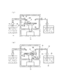
- FIG. 1 is a schematic diagram showing an example of the overall configuration of a resist developing apparatus to which the present invention is applied.
- the resist developing device 1 is roughly configured to include a development processing unit 10, a developer supply unit 20, a rinse solution supply unit (not shown), and a dew condensation prevention medium supply unit 30.
- a development processing unit 10 a developer supply unit 20
- a rinse solution supply unit not shown
- a dew condensation prevention medium supply unit 30 a dew condensation prevention medium supply unit
- the development processing unit 10 is a part that performs development processing on the substrate 2 that is an object to be processed.
- the substrate 2 to be developed is a substrate having an exposed resist layer.
- a mold manufacturing substrate (hereinafter also simply referred to as a “mold substrate”) for use in a nanoimprint method can be given.
- the mold substrate is a substrate made of a base material of a master mold that is a mold for transferring a pattern by the nanoimprint method or a master mold of a replication mold used for transferring a pattern by the nanoimprint method.
- the development processing unit 10 includes at least a processing chamber 11 having a space for development processing, a holding unit 12 that holds the substrate 2 in the processing chamber 11, and the holding unit.
- the processing chamber 11 may be a mechanism in which the ceiling portion is entirely or partially opened, or a mechanism that can be hermetically opened. May be.
- the holding unit 12 holds the base body 2 to be processed, and is configured using a table 12a that supports the base body 2 in a fixed state and a spindle shaft 12b connected to the table 12a.
- the table 12a is configured to horizontally support the base 2 from the lower surface side.
- the support structure by the table 12a may be, for example, a butting method using a pin or the like.
- the spindle shaft 12 b is a shaft that rotates the table 12 a with the driving force of the driving unit 13.
- the spindle shaft 12b is disposed so as to penetrate the bottom wall of the processing chamber 11 partitioned by a box-shaped wall.
- a seal member 14 is provided in a portion where the spindle shaft 12 b penetrates the bottom wall of the processing chamber 11. The seal member 14 prevents leakage of fluid (developer 21 and the like) from the penetrating portion of the spindle shaft 12b to the outside of the processing chamber 11 while allowing rotation of the spindle shaft 12b.
- the driving unit 13 is disposed in a lower chamber 15 that is partitioned from the processing chamber 11 by a wall.
- the drive unit 13 is configured using, for example, a motor serving as a rotation drive source and a drive force transmission mechanism (gear train or the like) that transmits the drive force of the motor to the spindle shaft 12b. .
- An operation panel (not shown) connected to a program controller (not shown) for controlling the operation of the resist developing apparatus may be installed on the exterior surface of the processing chamber 11. And with this program controller and the operation panel connected thereto, not only the rotation control of the holding unit 12 but also the control of the supply stop of the developer and the rinse solution, the temperature control of the fluid such as the developer and the rinse solution, The temperature inside the processing chamber 11 may be controlled.
- the developer supply unit 20 is a part that supplies a developer 21 for developing the substrate 2 to the substrate 2 held by the holding unit 12 in the processing chamber 11, and is a part of the fluid supply unit of the present invention. It functions as one.
- the developer supply unit 20 includes at least a storage unit 22 that stores the developer 21 and a supply pipe 23 that supplies (transports) the developer 21.
- the reservoir 22 is formed in a container shape that can store an appropriate amount of the developer 21.
- the developer 21 stored in the storage unit 22 is maintained in a constant temperature state by a liquid temperature adjustment control unit (not shown).
- a liquid temperature adjustment control unit for example, a cooling pipe, a heater for heating, and a stirrer are provided in the container of the storage unit 22 so that the refrigerant flows in contact with the developer 21.
- a mode is conceivable in which the temperature of the developer 21 is controlled and maintained at a predetermined temperature (hereinafter, “set temperature”).
- the temperature of the developer 21 in the reservoir 22 should be within an allowable range (eg, within ⁇ 0.1 ° C.) centered on a set temperature (eg, ⁇ 10 ° C.). To be controlled.
- the developer 21 is a liquid that does not freeze even at such a set temperature (for example, a temperature of 0 ° C. or lower).
- the supply pipe 23 supplies and spreads the developer 21 stored in the storage unit 22 toward the base 2 in the processing chamber 11.
- the supply pipe 23 is configured using, for example, an elongated hollow pipe having a circular cross section.
- One end of the supply pipe 23 is a take-in part 23a, and the other end is a discharge part 23b.
- the take-in part 23a of the supply pipe 23 is opened to take the developer 21 into the pipe.
- the discharge portion 23 b of the supply pipe 23 is opened to discharge and spray the developer 21 toward the base 2.
- the discharge part 23b may be a simple opening, or may have a structure like a shower head provided with a plurality of small openings.
- the discharge part 23b may be a structure which produces
- the take-in part 23 a of the supply pipe 23 is disposed in the storage part 22 of the developer supply part 20. Further, the discharge section 23 b of the supply pipe 23 is disposed in the processing chamber 11 of the development processing section 10.
- the supply pipe 23 is piped so that the flow path of the developer 21 is formed between the intake part 23a as the most upstream part and the discharge part 23b as the most downstream part.
- the supply pipe 23 is piped so as to lead out from the inside of the storage unit 22 to the outside. Further, the lead-out portion of the supply pipe 23 outside the storage unit 22 penetrates the outer wall portion of the development processing unit 10 to advance into the processing chamber 11 and is piped to a position facing the holding unit 12 in the processing chamber 11. Has been.
- the position facing the holding unit 12 is a position where the developer 21 discharged from the discharge unit 23b of the supply pipe 23 can be supplied and dispersed on the main surface (surface to be processed) of the substrate 2 held by the holding unit 12.
- the discharge portion 23 b located at the most downstream side of the supply pipe 23 is disposed immediately above the base 2 held by the holding portion 12.
- an on-off valve 24 and a pump 25 are provided in the middle of the supply pipe 23. Both the on-off valve 24 and the pump 25 constitute a function for controlling the flow of the developer 21 in the supply pipe 23.
- the on-off valve 24 allows the flow of the developing solution 21 and closes the supply pipe 23 by opening the pipe line of the supply pipe 23. By setting the state, the flow of the developer 21 is blocked.
- the on-off valve 24 supply of the developing solution 21 through the supply pipe 23 is started. Further, when the flow of the developer 21 is blocked by the on-off valve 24, the supply of the developer 21 through the supply pipe 23 is stopped. That is, the on-off valve 24 functions to start or stop the supply of the developer 21.
- the pump 25 When supplying the developer 21 through the supply pipe 23, the pump 25 applies pressure to the developer 21 for suction and transfer of the developer 21. That is, the pump 25 serves as a drive source for sucking the developer 21 stored in the storage unit 22 into the supply pipe 23 and transferring the sucked developer 21 through the supply pipe 23.
- the driving of the pump 25 is started or continued and when the on-off valve 24 is in an open state, a flow of the developing solution 21 is formed inside the supply pipe 23.
- the pump 25 is disposed outside the storage unit 22.
- the open / close state of the open / close valve 24 and the drive (on / off) state of the pump 25 can be controlled by, for example, a program controller (not shown) installed on the exterior surface of the processing chamber 11.
- the supply pipe 23 led out of the storage unit 22 is covered with a heat insulation jacket 26.
- the heat insulation jacket 26 is provided in a part of the supply pipe 23 as an example of a temperature adjustment unit.
- the heat insulation jacket 26 is interposed between the supply pipe 23 and the surrounding outside air (atmosphere) to form a temperature adjustment function, and more preferably, a heat medium is passed around the supply pipe 23 to circulate it.
- the developer 21 staying in the supply pipe 23 or the developer 21 moving in the supply pipe 23 is maintained at the same temperature (set temperature) as the inside of the storage unit 22 (heat retention function). Is.
- the heat insulation jacket 26 has, for example, a multiple tube structure (including a double tube structure) centered on the supply tube 23.
- the heat insulation jacket 26 has a triple tube structure including the supply tube 23 as shown in FIG.
- the supply pipe 23 is a pipe located on the innermost side, a second pipe 27 having a diameter larger than that of the supply pipe 23 is arranged on the outer side thereof, and a second pipe on the outer side (that is, the outermost side).
- a third tube 28 having a diameter larger than 27 is arranged.
- a coolant is circulated between the outer peripheral surface of the supply pipe 23 and the inner peripheral surface of the second pipe 27 in order to form a heat medium flow path 27a therein. It is supposed to be.
- air is filled or preferably a vacuum sealing mechanism is used.
- the heat insulation jacket 26 faces the holding portion 12 in the processing chamber 11 and the piping portion from the storage portion 22 to the processing chamber 11 of the development processing portion 10 in the length direction of the supply pipe 23. It is provided in a state of covering the supply pipe 23 in such a manner that it continues to the pipe portion reaching the discharge section 23b. Further, the heat insulation jacket 26 is a pipe portion extending from the storage section 22 to the processing chamber 11 of the development processing section 10 so as to cover the supply pipe 23 except for an attachment portion of the on-off valve 24 and an attachment portion of the pump 25. Is provided. Further, inside the processing chamber 11, a heat insulation jacket 26 is provided with the attachment portion of the on-off valve 24 as a terminal position.
- the rinsing liquid supply unit supplies a rinsing liquid that performs a process of stopping the developing action and cleaning the substrate 2 in the processing chamber 11 that has been processed with the developer 21 (hereinafter also simply referred to as “rinsing process”). And functions as another one of the fluid supply units of the present invention.
- the rinse liquid supply unit may have any configuration similar to that of the developer supply unit 20. That is, the rinse liquid supply unit is configured in the same manner as the developer supply unit 20 except that the type of liquid supplied to the substrate 2 is different from that of the developer supply unit 20.
- the dew condensation prevention medium supply unit 30 is a dew condensation prevention medium 31 that is a heat medium for adjusting the temperature of the substrate 2 with respect to the substrate 2 in the processing chamber 11 after the treatment with the developer 21 or the treatment with the rinse liquid. Is a mechanism for supplying and dispersing. That is, the dew condensation prevention medium supply unit 30 is compared with the developer supply unit 20 or the rinse liquid supply unit having the same configuration as the liquid type (or gas type) and liquid (or gas) to be supplied and sprayed to the substrate 2. Other than that, only the temperature is different, and the rest is configured similarly to the developer supply unit 20.
- the storage unit 32 may not include a temperature control unit such as the storage unit 22 of the developer supply unit 20 for the dew condensation prevention medium.
- the temperature of the dew condensation prevention medium is the normal temperature.
- the storage unit 32 may include a liquid temperature control unit such as the storage unit 22 of the developer supply unit 20. And if the temperature of a dew condensation prevention medium is made into the temperature higher from the said normal temperature, the temperature of the base
- the supply pipe 33 supplies and scatters the dew condensation prevention medium 31 stored in the storage unit 32 toward at least the main surface of the substrate 2 in the processing chamber 11.
- the supply pipe 33 may have only one discharge part 33b, or may have an individual discharge part 33b at each tip portion piped so as to branch on the downstream side (terminal side). It may be a thing.
- the supply pipe 33 has two discharge portions 33 b, and each discharge portion 33 b is against the main surface (resist layer formation surface) of the substrate 2 in the processing chamber 11 and the back surface thereof.
- positioned so that 31 may be distributed is shown.
- the temperature of the base body 2 can be brought closer to the temperature of the dew condensation prevention medium 31 more quickly.
- the discharge portions 33 b may be arranged at positions that overlap in a plane, or may be arranged at positions that are different from each other in a plane. Even if the supply pipe 33 has the two discharge portions 33b, only the main surface of the base 2 or the main surface is provided with the corresponding on-off valves (not shown). It is also conceivable that the dew condensation prevention medium 31 is selectively discharged to either the back surface or the back surface.
- the supply pipe 33 may not be covered with a heat insulation jacket. However, for example, when the temperature in the processing chamber 11 of the development processing unit 10 is low, the supply pipe 33 may be covered with a heat insulation jacket so as to avoid the influence on the dew condensation prevention medium 31. Absent.
- dew condensation prevention medium 31 supplied to the base body 2 by the dew condensation prevention medium supply unit 30 will be described in detail with a specific example.
- the anti-condensation medium 31 is applied to the substrate 2 that has been developed with the developer 21 at the set temperature (for example, ⁇ 10 ° C.) or the rinse liquid and is in a state lower than the atmospheric dew point temperature in the processing chamber 11. It is a heat medium for adjusting the temperature of the substrate 2 in order to prevent the dew condensation from occurring on the substrate 2 in the drying process immediately after that. More specifically, the dew condensation preventing medium 31 increases the temperature of the substrate 2 until it exceeds the atmospheric dew point temperature in order to prevent the dew condensation on the substrate 2.
- the “dew point temperature” is a temperature at which condensation starts when air containing water vapor is cooled, and is determined by the temperature and humidity of the atmosphere.
- the condensation prevention medium 31 is preferably a liquid heat medium as long as it can raise the temperature of the substrate 2 until it exceeds the atmospheric dew point temperature, but may be a gaseous heat medium. This is because a liquid medium has better thermal conductivity than a gaseous heat medium, and when discharged and dispersed on the substrate 2, the temperature of the substrate 2 can be increased more quickly and uniformly.
- the liquid form is also advantageous in that it can be handled easily.
- An example of such a dew condensation prevention medium 31 is one in which a poor solvent of a resist type to be processed is maintained at the normal temperature.
- the temperature of the ambient atmosphere around the substrate 2, that is, the temperature in the processing chamber 11 in which the substrate 2 is held, is processed during the resist development process by supplying and spraying a developer and a rinsing solution (that is, partial evaporation).
- the temperature inside the processing chamber 11 may decrease.
- normal temperature allows the substrate 2 at a temperature lower than the atmospheric dew point temperature to be raised to a temperature exceeding the atmospheric dew point temperature. This is because the condensation of No. 2 can be prevented and, therefore, the temperature adjustment function for the poor solvent is not required.
- the “poor solvent” is specifically a solvent having a low solubility in the constituent material of the resist layer in the substrate 2. Therefore, the “poor solvent” here is a fluid and heat medium that does not substantially dissolve the resist layer. If such a poor solvent is used, it is possible to suppress the fluid and the heat medium from dissolving the substrate 2 and to minimize the influence on the shape / quality or resolution of the developed resist pattern. Such a poor solvent is determined by the resist type to be processed. Specific examples include, for example, IPA (isopropyl alcohol), alcohol compounds such as methanol and ethanol, fluorine solvents such as fluorocarbon, Or any of water is mentioned.
- IPA isopropyl alcohol
- alcohol compounds such as methanol and ethanol
- fluorine solvents such as fluorocarbon, Or any of water is mentioned.
- the poor solvent as the dew condensation preventing medium 31 is preferably a fluorine-based solvent such as fluorocarbon. It is known that the surface free energy is small if it is a fluorine-based solvent such as fluorocarbon, and even if the aspect ratio of the resist pattern is large, there is a problem such as pattern collapse due to the surface free energy of the condensation prevention medium 31 This is because it is very effective in preventing the occurrence of the above.
- the heat medium as the dew condensation preventing medium 31 may be a gas that does not dissolve or react with the resist layer provided on the main surface of the substrate 2.
- Good. Specific examples include dry gas, particularly dry inert gas such as dry nitrogen gas, or dry air.
- the dry gas refers to a gas substantially free of moisture.
- fluorine-type gas such as a fluorocarbon gaseous at normal temperature, may be sufficient.
- a base 2 having a resist layer provided on a main surface on which a desired predetermined pattern is to be formed is prepared.
- Any resist material may be used as long as it has reactivity when exposed by irradiation with an energy beam.
- an electron beam drawing resist it is conceivable to use an electron beam drawing resist.
- a conductive material for preventing charge-up may be applied on the resist layer.
- the resist layer is a positive type resist
- the portion drawn by the electron beam becomes a punched portion after resist development, and corresponds to a groove position (concave portion) of a desired predetermined pattern in the mold to be manufactured.
- the electron beam drawn portion becomes a remaining portion after developing the resist and corresponds to a position (convex portion) other than the groove of the desired predetermined pattern in the mold to be manufactured.
- a case where a positive resist is used that is, a case where a portion drawn on the resist layer becomes a cut-out portion and corresponds to a groove position of a desired predetermined pattern will be described as an example.
- an exposure step of drawing a desired predetermined pattern on the resist layer on the substrate 2 is performed on the prepared substrate 2 using an electron beam drawing machine. That is, the main surface of the substrate 2 provided with the resist layer is irradiated with an electron beam as an energy beam, and the resist layer is exposed to a desired predetermined pattern.
- the desired predetermined pattern drawn in the exposure process may be on the micron order, but may be on the nano order from the viewpoint of the performance of electronic devices in recent years, and this is preferable in view of the performance of the final product.
- the substrate 2 on which the resist pattern has been formed through the development process, the dew condensation prevention process, and the drying process by the resist developing apparatus 1 is appropriately subjected to an etching process to the hard mask layer, the substrate 2 and the like thereafter. Thereby, a mold is manufactured.
- the mold for nanoimprint was manufactured here was demonstrated, as long as it performs using a lithography technique, it is not limited to manufacture of the mold for nanoimprint.
- FIG. 3 is a schematic view showing an operation example in the resist developing apparatus to which the present invention is applied.
- the operation of the resist developing apparatus 1 may be performed based on a control command from a program controller provided in the resist developing apparatus 1.
- the developer supply unit 20 of the resist developing apparatus 1 stores the developer 21 in the storage unit 22 and the developer 21 is stored at a desired set temperature (for example, ⁇ 10 ° C).
- a desired set temperature for example, ⁇ 10 ° C.
- the development processing unit 10 of the resist developing apparatus 1 places the base 2 on the table 12a of the holding unit 12 and then supports it by fixing it.
- the drive unit 13 is driven to rotate the spindle shaft 12b.
- the base body 2 is rotated integrally with the spindle shaft 12b.
- the developer supply unit 20 drives the pump 25 and opens the on-off valve 24 to open the storage unit 22.
- the developer 21 is taken into the supply pipe 23 and sent out to the development processing unit 10 side through the supply pipe 23.
- the developer 21 is discharged and dispersed from the discharge portion 23b located on the most downstream side of the supply pipe 23 (see A in the figure).
- the substrate 2 is horizontally supported by the table 12a of the holding unit 12 and the table 12a is rotated by driving of the driving unit 13, the developer 21 discharged from the discharge unit 23b of the supply pipe 23 is transferred to the substrate. 2 is supplied to the entire main surface (surface to be processed). As a result, unnecessary and soluble portions of the exposed resist layer formed on the surface (upper surface) of the substrate 2 are dissolved and removed with the developer 21.
- the developing solution supply unit 20 stops the supply of the developing solution 21 by switching the on-off valve 24 from the open state to the closed state, and then the pump 25 as necessary. Stop driving.
- a rinsing liquid supply unit (not shown) supplies and sprays the rinsing liquid to the substrate 2 in the processing chamber 11 to perform a rinsing process. And after finishing the process by a rinse liquid, a rinse liquid supply part stops supply of a rinse liquid. Thus, the development process ends.
- the developing solution 21 supplied to the substrate 2 preferably both the developing solution 21 and the rinsing solution are supplied at a desired set temperature (for example, ⁇ 10 ° C.). That is, for the developer 21 and the rinse solution that are supply solutions to the exposed resist layer, at least the developer solution 21 is supplied to the resist layer at a low temperature as described above.
- a desired set temperature for example, ⁇ 10 ° C.
- the substrate 2 immediately after the development processing and the rinsing processing are finished is cooled by the developer 21 or the rinsing solution, and the temperature of the substrate 2 becomes lower than the dew point temperature of the surrounding atmosphere.
- condensation occurs on the surface of the substrate 2 at the moment when the developer 21 or the rinse solution evaporates and the surface of the substrate 2 (ie, the resist pattern) is exposed.
- the occurrence of condensation on the surface of the substrate 2 may cause a problem called pattern collapse when the condensation (water) evaporates as the drying process proceeds, and may result in degradation of the resolution of the resist pattern. Therefore, the occurrence should be prevented.
- the resist developing apparatus 1 is a medium that adjusts the temperature of the substrate 2 with respect to the substrate 2 in the processing chamber 11 after the development processing is completed and before the drying process performed thereafter.
- the dew condensation prevention process which supplies the prevention medium 31 is performed. That is, the dew condensation prevention medium supply unit 30 of the resist developing apparatus 1 distributes the developing solution 21 to the substrate 2 that is in a temperature lower than the atmospheric dew point temperature by supplying the developing solution 21 and the like.
- the dew condensation prevention medium 31 is supplied immediately before or simultaneously with the stop. And so that the developed resist pattern is not exposed to the outside air (moisture-containing air), the developer and the immersion with the anti-condensation medium are continuously maintained. And the temperature of the said base
- the dew condensation prevention medium supply unit 30 stores the dew condensation prevention medium 31 in the storage unit 32.
- the dew condensation preventing medium 31 to be stored may remain at room temperature. Therefore, a liquid temperature adjustment control means like the storage part 22 of the developer supply part 20 is not required.
- the dew condensation prevention medium supply unit 30 supplies the dew condensation prevention medium 31 in the storage unit 32 by driving the pump 35 and opening the on-off valve 34. While taking into the pipe 33, the dew condensation prevention medium 31 is sent out to the development processing unit 10 side through the supply pipe 33. Then, the dew condensation preventing medium 31 is discharged and dispersed from the discharge portion 33b located on the most downstream side of the supply pipe 33 (see B in the figure).
- the dew condensation prevention medium 31 discharged from the discharge unit 33 b of the supply pipe 33 is obtained. It is supplied and dispersed over the entire main surface (surface to be treated) of the substrate 2. As a result, heat exchange is performed between the base 2 in a state below the atmospheric dew point temperature and the dew condensation prevention medium 31 at room temperature, and the temperature of the base 2 rises until it exceeds the atmospheric dew point temperature.
- the dew condensation prevention medium 31 can be sprayed and dispersed on the base body 2 with a simple configuration on both the main surface and the back surface thereof. This is because the temperature of the substrate 2 can be more quickly made higher than the atmospheric dew point temperature or the temperature of the dew condensation preventing medium 31 (that is, normal temperature) as compared with the case of performing on one side. That is, there is a possibility that the consumption of the dew condensation prevention medium can be further reduced. Furthermore, it is also conceivable that the anti-condensation medium 31 is sprayed and dispersed on both surfaces of the base 2 from three or more ejection parts.
- the dew condensation medium 31 may be discharged and dispersed on the base 2 at least on the main surface of the base 2 (the side where the resist pattern is formed). That is, the spraying of the dew condensation prevention medium 31 may be performed only on the main surface (surface to be processed) of the base 2 or on both the main surface and the back surface. If the dew condensation prevention medium 31 is discharged and dispersed at least on the main surface of the substrate 2, the resist pattern formed by the development process is immersed in the dew condensation prevention medium 31 without being exposed to the outside air, and no dew condensation occurs. Further, this is because the temperature of the substrate 2 can be adjusted (temperature increase until it exceeds the atmospheric dew point temperature) by heat exchange with the dew condensation prevention medium 31.
- the opening / closing valve 34 is opened from the open state to the closed state when a predetermined time has elapsed from the start of the discharge and spraying of the dew condensation prevention medium 31 to the substrate 2 until the temperature of the substrate 2 exceeds the atmospheric dew point temperature.
- the dew condensation prevention medium supply unit 30 stops the supply of the dew condensation prevention medium 31. Thereafter, the drive of the pump 35 is stopped as necessary.
- a function for detecting the temperature of the substrate 2 such as an infrared temperature sensor, is provided in the processing chamber 11, the temperature of the substrate 2 exceeds the atmospheric dew point temperature while referring to the temperature detection result.
- the supply of the anti-condensation medium 31 may be stopped when a time taking into account the safety factor is added. That is, when the dew condensation prevention medium supply unit 30 stops supplying the dew condensation prevention medium 31, the substrate 2 in the processing chamber 11 is heated to a temperature that exceeds the atmospheric dew point temperature through heat exchange with the dew condensation prevention medium 31. Has risen sufficiently.
- the development processing unit 10 of the resist developing apparatus 1 continuously drives the drive unit 13 while the base 2 is supported on the table 12a of the holding unit 12, and rotates the spindle shaft 12b in the development process. Rotate faster than number.
- the table 12a supporting the substrate 2 is rotated integrally with the spindle shaft 12b, and the substrate 2 is spin-dried.
- the rotational speed of the spindle shaft 12b the rotational speed of the spindle shaft 12b in the development process and the dew condensation prevention process is 50 to 500 rpm, whereas the rotational speed of the spindle shaft 12b in the drying process is 1000 rpm. Or up to about 3000 rpm.
- the rotation speed of the spindle shaft 12b in the development process, the dew condensation prevention process, and the drying process is not limited to this.
- the temperature of the base body 2 has already exceeded the atmospheric dew point temperature and has risen to room temperature through the above-described dew condensation prevention process. That is, the temperature is higher than the atmospheric dew point temperature. Therefore, even if the drying process starts and evaporation of the dew condensation prevention medium starts by the start of spin drying, dew condensation does not occur on the main surface of the substrate 2, that is, the resist pattern.
- the gaseous dew condensation prevention medium may be used in place of the liquid dew condensation prevention medium.
- a dew condensation prevention medium made of the gas at room temperature is sprayed onto the substrate 2 to start the dew condensation prevention process.
- the developer and / or the rinsing liquid remaining on the surface of the gas 2 is evaporated by spraying the dew condensation prevention medium made of the gas, and the resist pattern is exposed to the gas.
- the dew condensation preventing medium made of the gas does not substantially contain water, dew condensation does not occur on the substrate 2.
- the rinse liquid when the treatment with the rinse liquid is performed following the treatment with the developer 21, the rinse liquid may be used as the dew condensation preventing medium 31. That is, a rinse liquid set to a temperature higher than the atmospheric dew point temperature may be discharged and sprayed onto the substrate 2 after the processing with the developer set to the atmospheric dew point temperature or lower.
- a rinse liquid set to a temperature higher than the atmospheric dew point temperature may be discharged and sprayed onto the substrate 2 after the processing with the developer set to the atmospheric dew point temperature or lower.
- the atmosphere is subsequently continued.
- a rinse liquid adjusted and set to a temperature (including normal temperature) higher than the dew point temperature may be used as the dew condensation preventing medium 31.
- the drying treatment with respect to the substrate 2 is started until the drying treatment is started.
- the substrate 2 is brought to a temperature higher than the atmospheric dew point temperature by supplying and spraying the dew condensation prevention medium 31 to the substrate 2.
- condensation occurs on the surface of the resist pattern during the drying process, and when the condensation evaporates, there is no occurrence of attraction caused by the capillary action of condensation (water) between the developed resist patterns.
- condensation water
- no trace of condensation remains on the substrate 2, and the trace of condensation remains as a foreign substance on the resist pattern or the surface of the substrate, adversely affecting the pattern quality after the subsequent etching process. The possibility of affecting can be eliminated.
- the room temperature is higher than the atmospheric dew point temperature.
- the substrate 2 can be reliably placed at a temperature higher than the atmospheric dew point temperature.
- it since it is a poor solvent, it can also suppress that the dew condensation prevention medium 31 melt
- the fluorine-based solvent such as fluorocarbon
- the fluorine-based solvent is known to have a small surface free energy, and thus the resist pattern has a large aspect ratio. Even so, it is very effective in preventing the occurrence of problems such as pattern collapse due to evaporation of the condensation prevention medium in the drying process.
- the dew condensation preventing medium 31 is a material having high volatility and a large evaporation heat, such as a fluorinated solvent.
- FIG. 4 is a schematic diagram showing an example of the overall configuration of a resist developing apparatus to which the second embodiment of the present invention is applied.
- the resist developing apparatus 1 ′ is roughly divided into a developing processing unit 10 ′, a developing solution supply unit 20 ′, a rinsing liquid supply unit (not shown), a dew condensation prevention medium supply unit 30 ′, and a heat loss compensation medium. And a supply unit 40 ′.
- the components 10 ′, 20 ′, and 30 ′ have the same configurations as the components 10, 20, and 30 of the first embodiment.
- the heat loss compensation medium supply unit 40 ′ will be described in detail below.
- the heat loss compensation medium supply unit 40 ′ compensates for the heat loss of the base 2 ′ in the base 2 ′ in the processing chamber 11 ′ after finishing the process using the dew condensation prevention medium 31 ′ and starting the drying process. This is a mechanism for supplying and dispersing a heat loss compensation medium 41 ′ made of a heat medium for the purpose.
- the heat loss compensation medium supply unit 40 ′ includes at least a supply source 42 ′ of the heat loss compensation medium 41 ′ and a supply pipe 43 ′ that supplies (transports) and disperses the heat loss compensation medium 41 ′.
- the supply source 42 ′ stores the heat loss compensation medium 41 ′ in the same manner as in the case of the developer supply unit 20 ′, the liquid supply unit 30 ′, etc., in order to provide the heat loss compensation medium 41 ′ that is in a gaseous state.
- Obtaining containers eg gas cylinders
- the heat loss compensation medium 41 ′ may be one obtained by vaporizing a liquid raw material to produce the heat loss compensation medium 41 ′, or one produced by dehydration separation from a raw material gas (for example, air).
- the supply source 42 ′ does not require a temperature control means for cooling like the storage unit 22 ′ of the developer supply unit 20 ′. However, any temperature control means for heating the heat loss compensation medium 41 ′ may be provided. Details of the heat loss compensation medium 41 ′ supplied by the supply source 42 ′ will be described later.
- the supply pipe 43 ′ supplies and scatters the heat loss compensation medium 41 ′ provided from the supply source 42 ′ toward the base body 2 ′ in the processing chamber 11 ′.
- the supply pipe 43 ′ is configured using, for example, an elongated hollow pipe having a circular cross section, like the supply pipe 23 ′ of the developer supply section 20 ′ or the supply pipe 33 ′ of the dew condensation prevention medium supply section 30 ′. ing. Then, one end of the supply pipe 33 ′ is an intake portion 43a ′, and the other end is an ejection portion 43b ′.
- the intake portion 43a ′ is the most upstream portion, and the ejection portion 43b ′ is the most downstream portion.
- piping is provided so as to form a flow path of the heat loss compensation medium 41 ′ between them.
- the intake section 43a ′ of the supply pipe 43 ′ communicates with the supply source 42 ′ of the heat loss compensation medium supply section 40 ′, and the ejection section 43b ′ of the supply pipe 43 ′ is the processing chamber of the development processing section 10 ′. 11 '.
- At least an on-off valve 44 ′ is provided in the middle of the supply pipe 43 ′.
- the on-off valve 44 ' is a mechanism for controlling the flow of the heat loss compensation medium 41' in the supply pipe 43 '.
- a pressure control mechanism or a flow rate control mechanism may be provided in the middle of the supply pipe 43 '.
- the pressure control mechanism or the flow rate control mechanism is a mechanism for controlling the supply spraying pressure or flow rate of the heat loss compensation medium 41 ′ to the base 2 ′.
- the supply pipe 43 ′ may not be covered with a heat insulation jacket. However, for example, when the temperature in the processing chamber 11 ′ of the development processing unit 10 ′ becomes low, the supply pipe 43 ′ is covered with a heat insulating jacket so as to avoid the influence on the heat loss compensation medium 41 ′. It doesn't matter if you do. This is the same as the case of the supply pipe 33 ′ of the dew condensation prevention medium supply unit 30 ′.
- the heat loss compensation medium supply unit 40 ′ may have only one ejection part 43b ′ of the supply pipe 43 ′ or may have a plurality.
- the heat loss compensation medium supply unit 40 ′ has one ejection part 43b ′, and the ejection part 43b ′ is the main surface of the substrate 2 ′ in the processing chamber 11 ′ (resist layer formation surface).
- the heat loss compensation medium 41' can be supplied with a simple configuration.
- each ejection part 43b ' may be distribute
- each of the ejection portions 43 b ′ has respective tip portions of the supply pipes 43 ′ piped so as to branch on the downstream side (terminal side). It is conceivable to provide them individually.
- the supply pipe 43 ′ may not be branched, and the supply source 42 ′ and the supply pipe 43 ′ may be provided separately corresponding to each ejection part 43 b ′. In that case, different types of heat loss compensation media 41 ′ can be supplied to the main surface side and the back surface side of the base 2 ′.
- a heat loss compensation medium 41 ′ that is selective to the main surface side and the back surface side of the base 2 ′ is provided. You will be able to erupt.
- the heat loss compensation medium 41 ′ is used during the drying process for drying the substrate 2 ′ having the resist pattern formed on the main surface or after the drying process after the supply and dispersion of the dew condensation preventing medium 31 ′ is stopped. Since heat is removed from the base body 2 'by the evaporation of the dew condensation preventing medium 31', the heat medium is used to compensate for heat loss caused by the evaporation. More specifically, the heat loss compensation medium 41 ′ is deprived of heat by evaporation of the dew condensation prevention medium 31 ′ during or after the drying process after the supply and dispersion of the dew condensation prevention medium 31 ′ is stopped.
- the heat loss compensation medium 41 ′ is preferably a gaseous heat medium that can compensate for the heat loss of the substrate 2 ′ and increase the temperature of the substrate 2 ′. This is because heat loss due to evaporation does not become a problem with a gaseous heat medium as in a liquid medium. Moreover, if it is a gaseous heat medium, the resist pattern once dried will not be immersed in a liquid again. Therefore, it is possible to avoid the possibility that the above-described defect called pattern collapse occurs. Furthermore, even after drying, it is possible to avoid the possibility that dew traces remain on the resist pattern or the surface of the substrate as foreign matter and affect the pattern quality after the subsequent etching process.
- An example of such a heat loss compensation medium 41 ′ is dry nitrogen gas at room temperature. If it is normal temperature, the substrate 2 ′ that is deprived of heat and is going to the ambient dew point temperature or a temperature lower than that can be reliably maintained at a higher temperature than the ambient dew point temperature. For this reason, the temperature adjustment function for the heat loss compensation medium 41 ′ is not required.
- dry nitrogen gas is effective in preventing condensation because it is in a dry state that does not contain moisture, and further, it suppresses dissolution or reaction of the substrate 2 'due to the inert gas. it can.
- the substrate 2 ′ that has undergone the exposure process is subjected to the development process for developing the resist layer using the resist developing apparatus 1 ′ having the above-described configuration, and the dew condensation prevention process that is performed after the development process. And the drying process performed after the said condensation prevention process and the heat loss compensation process which starts simultaneously with the start of a drying process or a little behind are performed in order, respectively.
- These development step, dew condensation prevention step, and drying step are the same as in the first embodiment. Details of the heat loss compensation process will be described.
- the resist developing apparatus 1 ′ applies the heat loss compensation medium to the substrate 2 ′.
- the heat loss compensation process of supplying and spreading 41 ′ is started. That is, the heat loss compensation medium supply unit 40 ′ of the resist developing apparatus 1 ′ again moves to the atmospheric dew point temperature in the processing chamber 11 ′ or a temperature lower than that due to evaporation accompanying the stop of supply and dispersion of the dew condensation prevention medium 31 ′.
- the supply and dispersion of the heat loss compensation medium 41 ′ is performed on the base body 2 ′. Then, the temperature of the substrate 2 ′ is raised so as to compensate for the heat loss of the substrate 2 ′ and maintain the substrate 2 ′ at a temperature higher than the atmospheric dew point temperature.
- the heat loss compensation medium supply unit 40 ′ stores the heat loss compensation medium 41 ′ in the form of gas in the storage unit 42 ′.
- the heat loss compensation medium 41 ′ is generated by vaporizing a liquid raw material stored in a container (for example, a gas cylinder) which is the storage portion 42 ′, or generated by dehydration separation from a raw material gas (for example, air). There may be.
- the stored heat loss compensation medium 41 may be at room temperature. Accordingly, the supply source 42 ′ does not require a temperature adjustment control unit for cooling like the storage unit 22 ′ of the developer supply unit 20 ′. However, any temperature control means for heating the heat loss compensation medium 41 ′ may be provided.
- One end of the supply pipe 43 ′ is a take-in portion 43a ′, and the other end is an ejection portion 43b ′.
- the intake portion 43a ′ is the most upstream portion, and the ejection portion 43b ′ is the most downstream portion. Between them, piping is formed so as to form a flow path of the heat loss compensation medium 41 ′.
- the intake section 43a ′ of the supply pipe 43 ′ communicates with the supply source 42 ′ of the heat loss compensation medium supply section 40 ′, and the ejection section 43b ′ of the supply pipe 43 ′ is the processing chamber of the development processing section 10 ′. 11 '.
- the pressure regulating valve or flow rate regulator is a mechanism for controlling the pressure or flow rate of supply and dispersion of the heat loss compensation medium 41 ′ with respect to the base 2 ′
- the on-off valve 44 ′ is the heat loss compensation medium 41 in the supply pipe 43 ′. It is a mechanism for controlling the flow of '.
- FIG. 5A is a schematic diagram showing a change in the temperature of the substrate over time when the mold manufacturing substrate is processed by the configuration of a conventional general liquid supply device (resist developing device).
- a conventional general liquid supply device resist developing device.
- the temperature of the substrate at room temperature drops to the same temperature as the set temperature, and the processing with the developer ends. That is, the temperature is maintained until the supply of the developing solution is finished.
- the process by the rinse liquid is similarly performed.
- the temperature of the substrate rises slightly when switching from the developer to the rinse liquid. Maintained.
- FIG. 5B shows a case where a mold manufacturing substrate is processed by the configuration described in the first embodiment of the present invention, and a substance having relatively low volatility and relatively small evaporation heat is used. It is a schematic diagram which shows the time-dependent change of the temperature of the said board
- the temperature of the substrate at room temperature drops to the same temperature as the set temperature, and the processing with the developer ends. That is, the temperature is maintained until the supply of the developing solution is finished.
- the process by a rinse liquid is performed.
- the temperature of the substrate rises slightly when switching from the developer to the rinse liquid. Maintained.
- the supply and dispersion of the dew prevention medium at room temperature is started.
- the substrate is not exposed to the outside air, that is, condensation does not occur. Then, at the same time as the supply and distribution of the dew condensation prevention medium at normal temperature is started, the temperature of the substrate starts to rise toward normal temperature. Thereafter, the supply / spreading of the dew condensation prevention medium is continued, and the supply / spreading of the dew condensation prevention medium is stopped when the temperature of the substrate reaches room temperature and is stabilized. Then, the heat of the substrate is taken away by the evaporation of the dew condensation prevention medium described herein, and the temperature of the substrate may again reach the atmospheric dew point temperature.
- FIG. 5 (b ′) shows a case where the mold manufacturing substrate is processed by the configuration described in the first embodiment of the present invention, and is a substance having a relatively high volatility and a relatively large evaporation heat. It is a schematic diagram which shows the time-dependent change of the temperature of the said board
- the temperature of the substrate at room temperature drops to the same temperature as the set temperature, and the processing with the developer ends. That is, the temperature is maintained until the supply of the developing solution is finished.
- the process by a rinse liquid is performed.
- the temperature of the substrate rises slightly when switching from the developer to the rinse liquid. Maintained.
- the supply and dispersion of the dew prevention medium at room temperature is started.
- the substrate is not exposed to the outside air, that is, condensation does not occur. Then, at the same time as the supply and distribution of the dew condensation prevention medium at normal temperature is started, the temperature of the substrate starts to rise toward normal temperature. Thereafter, the supply / spreading of the dew condensation prevention medium is continued, and the supply / spreading of the dew condensation prevention medium is stopped when the temperature of the substrate reaches room temperature and is stabilized. Then, the heat of the substrate is taken away by the evaporation of the dew condensation prevention medium described herein, and the temperature of the substrate may again reach the atmospheric dew point temperature.
- FIG.5 (c) is a schematic diagram which shows the time-dependent change of the temperature of the said board
- the temperature of the substrate at room temperature drops to the same temperature as the set temperature, and the processing with the developer ends.
- the temperature is maintained until the supply of the developing solution is finished.
- the process by a rinse liquid is performed.
- the temperature of the substrate rises slightly when switching from the developer to the rinsing liquid. Maintained.
- the stop of the rinse liquid that is, the supply and dispersion of the dew condensation prevention medium is started.
- the substrate is not exposed to the outside air, that is, condensation does not occur.
- the temperature of the substrate starts to rise toward normal temperature.
- the supply / spreading of the dew condensation prevention medium is continued, and the supply / spreading of the dew condensation prevention medium is stopped when the substrate temperature reaches room temperature and is stabilized. Then, the heat of the substrate is deprived by the evaporation of the dew condensation prevention medium described, and the substrate temperature may again reach the atmospheric dew point temperature. In this case, depending on the type of the dew condensation prevention medium, if left as it is, the temperature of the substrate reaches the atmospheric dew point temperature or falls below the atmospheric dew point temperature. Therefore, before the temperature of the substrate reaches the atmospheric dew point, supply and distribution of the heat loss guarantee medium at normal temperature is started. At the same time, the temperature of the substrate begins to rise again toward room temperature, and then reaches room temperature and stabilizes.
- the object to be processed can be maintained at a temperature higher than the atmospheric dew point temperature by supplying and dispersing the heat loss compensation medium in the heat loss compensation process. Therefore, in the drying process, after evaporating the dew condensation preventing medium, the temperature of the object to be treated is deprived by the evaporation of the dew condensation preventing medium, and again to the object to be treated to reach the atmospheric dew point temperature or lower temperature.
- the heat loss compensation medium it is possible to maintain the substrate to be processed at a temperature higher than the atmospheric dew point temperature and to prevent dew condensation from occurring on the surface of the workpiece. Accordingly, it is possible to avoid the occurrence of defects due to condensation, such as defects such as pattern collapse and traces of condensation.
- the anti-condensation medium 31 does not necessarily have to be at room temperature. If the temperature of the substrate 2 can be increased until it exceeds the atmospheric dew point temperature, it is higher than the atmospheric dew point temperature but lower than room temperature. Alternatively, it may be heated by a temperature control means and be in a temperature higher than normal temperature. If the anti-condensation medium 31 having a temperature higher than room temperature is used, the temperature of the substrate 2 can be increased more quickly than when the anti-condensation medium 31 is at room temperature.
- the heat loss compensation medium 41 ′ is not necessarily a gas at normal temperature, and may be higher than the atmospheric dew point temperature as long as the temperature of the substrate 2 ′ can be raised and maintained so as not to fall below the atmospheric dew point temperature. However, the temperature may be lower than normal temperature, or may be heated by temperature control means to be higher than normal temperature. If the heat loss compensation medium 41 ′ having a temperature higher than room temperature is used, the temperature of the substrate 2 ′ can be increased rapidly as compared with the case where the heat loss compensation medium 41 ′ is at room temperature.
Landscapes
- Engineering & Computer Science (AREA)
- Chemical & Material Sciences (AREA)
- Nanotechnology (AREA)
- Physics & Mathematics (AREA)
- General Physics & Mathematics (AREA)
- Crystallography & Structural Chemistry (AREA)
- Condensed Matter Physics & Semiconductors (AREA)
- Manufacturing & Machinery (AREA)
- Mathematical Physics (AREA)
- Theoretical Computer Science (AREA)
- Photosensitive Polymer And Photoresist Processing (AREA)
- Exposure Of Semiconductors, Excluding Electron Or Ion Beam Exposure (AREA)
Abstract
被処理物を保持する保持部12と、前記保持部12が保持する前記被処理物に対して流体の供給散布を行う流体供給部20と、前記流体が供給散布されて雰囲気露点温度より低い温度にある前記被処理物に対して、前記雰囲気露点温度より高い温度にある状態にする結露防止媒体31の供給散布を行う結露防止媒体供給部30と、を備えて流体供給装置1を構成する。
Description
本発明は、流体供給装置、レジスト現像装置およびモールド製造方法に関する。
被処理物に液体を供給散布して処理する液体供給装置は、これまでに数多く知られている。たとえば、リソグラフィの分野で用いられる液体供給装置の一例として、レジスト現像装置が知られている(たとえば、特許文献1を参照)。レジスト現像装置は、露光または描画(以下、「露光」ともいう)を経たレジスト層に現像液またはさらにリンス液を供給散布することで、レジスト層の不要部分を溶解除去して現像(以下、「現像処理」ともいう)を行い、レジストパターンを形成する装置である。
ところで近年、半導体デバイスの高集積化やパターンドメディアの開発及び高記録密度化などに伴って、レジストパターンの一層の高解像化が強く望まれている。そして、上記のレジストパターンの形状・品質の劣化を抑え、レジストパターンの解像度の向上を図る技術として、常温よりも低い温度の現像液を用いてレジスト現像する方法(以下、「低温現像法」ともいう)が知られている(たとえば、非特許文献1を参照)。
レジストパターン形成では、レジスト層を露光した後に形成される溶解部と非溶解部の現像液に対する溶解性(速度)の差が大きいほど、コントラストが高いレジストパターンが得られ、解像性は向上する。一方で、レジスト現像によって、本来全く溶解されてはならないレジストパターン部(非溶解部)も、僅かに溶解される。その結果、現像処理後に得られるレジストパターンの断面形状においては、レジストパターンの高さが減少し、かつ、肩部の鉛直形状が丸まり、また、側壁の平滑性が損なわれ、その形状・品質は劣化し、さらには、解像度の低下を招いてしまう。
そこで、常温よりも低い温度の現像液を用いてレジスト現像を行うと、レジスト層に対する現像液の溶解性(速度)が低下して、特にレジストパターン部(非溶解部)の溶解が抑制される。その結果、前記溶解部と非溶解部の現像液に対する溶解性(速度)の差はより大きくなり、レジストパターンの形状・品質は向上して、また、解像度の向上が図られる。
また、現像処理後に必要に応じて実施されるリンス液によるリンス処理についても同様に、常温よりも低い温度に調整制御されたリンス液を用いてリンス処理を行うと、レジスト層に対するリンス液の溶解性(速度)が低下して、特にレジストパターン部(現像液による非溶解部)の溶解あるいは膨潤が抑制される。その結果、リンス処理によるレジストパターンの変形等が抑えられ、現像後のレジストパターンの形状・品質が維持されて、解像度の維持が図られる。
ちなみに、本明細書で記述する「常温」とは、たとえば半導体製造用の無塵室(クリーンルーム)の一般的な設定温度である22.5℃前後をいう。前記無塵室の温度制御の精度は、一般に、設定値+/-0.1℃から+/-1℃程度である。したがって、低温現像法で用いる現像液の温度は、たとえば、21.5℃未満となる。また、より良好なレジストパターン形状・品質と高い解像度を得るためには、現像液が凍らない温度範囲(凝固点より高い温度)であって、かつ、液温度の調整制御が実用的に可能な温度を用いることができる。一例を挙げると、非特許文献1に記載の、-10℃、-60℃、等が選定され、現像液、及びリンス液、は当該温度に設定される。
そこで、常温よりも低い温度の現像液を用いてレジスト現像を行うと、レジスト層に対する現像液の溶解性(速度)が低下して、特にレジストパターン部(非溶解部)の溶解が抑制される。その結果、前記溶解部と非溶解部の現像液に対する溶解性(速度)の差はより大きくなり、レジストパターンの形状・品質は向上して、また、解像度の向上が図られる。
また、現像処理後に必要に応じて実施されるリンス液によるリンス処理についても同様に、常温よりも低い温度に調整制御されたリンス液を用いてリンス処理を行うと、レジスト層に対するリンス液の溶解性(速度)が低下して、特にレジストパターン部(現像液による非溶解部)の溶解あるいは膨潤が抑制される。その結果、リンス処理によるレジストパターンの変形等が抑えられ、現像後のレジストパターンの形状・品質が維持されて、解像度の維持が図られる。
ちなみに、本明細書で記述する「常温」とは、たとえば半導体製造用の無塵室(クリーンルーム)の一般的な設定温度である22.5℃前後をいう。前記無塵室の温度制御の精度は、一般に、設定値+/-0.1℃から+/-1℃程度である。したがって、低温現像法で用いる現像液の温度は、たとえば、21.5℃未満となる。また、より良好なレジストパターン形状・品質と高い解像度を得るためには、現像液が凍らない温度範囲(凝固点より高い温度)であって、かつ、液温度の調整制御が実用的に可能な温度を用いることができる。一例を挙げると、非特許文献1に記載の、-10℃、-60℃、等が選定され、現像液、及びリンス液、は当該温度に設定される。
XiaoMin Yang et.al.J.Vac.Sci.Technol.B 25(6),Nov/Dec 2007 p.2202
しかしながら、現像液またはさらにリンス液(以下、「現像液」ともいう)の温度が周辺雰囲気の温度と湿度から決定される露点温度(以下、「雰囲気露点温度」ともいう)より低い温度に設定される場合には、現像液による処理の後、またはさらにリンス液による処理の後、即ち、これらの現像処理に続く乾燥処理の直前及び乾燥処理の際中においては、被処理基板及びその主表面にあるレジストパターンの温度も前記雰囲気露点温度を下回っている。その結果、前記現像液の供給散布を停止した後の乾燥処理において、前記現像液が蒸発し、被処理基板の表面(即ち、レジストパターン)が露出された瞬間に結露が生じてしまう。レジストパターンに結露が生じると、その結露の乾燥の際に結露(水)の毛管現象に起因する引力が現像処理によって形成されたレジストパターン間に働き、その結果、パターン倒れと呼ばれる不具合が生じてしまう可能性がある。さらには、乾燥後においても、結露の痕跡が異物としてレジストパターンあるいは基板の表面に残存してしまい、続くエッチング処理の後のパターン品質に悪影響を及ぼす可能性がある。
したがって、前記雰囲気露点温度より低い温度の現像液を用いてレジスト層を現像処理する場合には、何らかの方策を用いて、現像処理後の基板の表面に、即ち、現像処理して形成されたレジストパターンの表面に、結露が生じるのを未然に防止する必要がある。
本発明は、前記雰囲気露点温度より低い温度に設定維持された現像液を供給散布して被処理物、即ち露光を経たレジスト層付き基板、を現像処理した結果、当該被処理物の温度が前記雰囲気露点温度を下回っている場合であっても、現像液の供給散布を停止した後の乾燥処理の最中、あるいはまた、乾燥工程を終えた後に、前記非処理物に結露が生じるのを防止して、それに起因する不具合の発生、たとえば前記レジストパターンの倒れ等の不具合発生、を未然に回避することのできる流体供給装置、レジスト現像装置およびモールド製造方法、を提供することを主たる目的とする。
本発明は、上記目的を達成するために案出されたものである。
本発明の第1の態様は、被処理物あるいは被処理物を含む基体(以下、「被処理物」ともいう)を保持する保持部と、
前記保持部が保持する前記被処理物に対して流体の供給散布を行う流体供給部と、
前記流体が供給散布されて雰囲気露点温度より低い温度にある前記被処理物に対して、前記雰囲気露点温度より高い温度にある状態にする結露防止媒体の供給散布を行う結露防止媒体供給部と、
を備えることを特徴とする流体供給装置である。
本発明の第2の態様は、第1の態様に記載の発明において、前記結露防止媒体は、被処理物を溶解損傷しない流体であることを特徴とする。
本発明の第3の態様は、第1または第2の態様に記載の発明において、
前記結露防止媒体の供給散布を停止し、続いて、前記被処理物の乾燥処理を行う最中、あるいは乾燥処理を終えた後に、再び雰囲気露点温度あるいはそれ低い温度に向かおうとする前記被処理物を、雰囲気露点温度より高い温度にある状態を維持すべく、被処理物の熱損失を補填する熱損失補填媒体を前記被処理物に対して供給散布する熱損失補填媒体供給部を更に備えることを特徴とする。
本発明の第4の態様は、被処理物に現像液を供給散布して現像処理を含む処理を行うレジスト現像装置であって、
前記基板を保持する保持部と、
前記基板に対して前記現像液の供給散布を行う現像液供給部と、
前記現像液による処理がなされて雰囲気露点温度より低い温度にある前記基板に対して、当該基板を前記雰囲気露点温度より高い温度にある状態にする結露防止媒体の供給を行う結露防止媒体供給部と、
備えることを特徴とするレジスト現像装置である。
本発明の第5の態様は、第4の態様に記載の発明において、前記結露防止媒体は被処理対象であるレジスト層の貧溶媒であり、かつ、雰囲気露点温度より高い温度であることを特徴とする。
本発明の第6の態様は、第5の態様に記載の発明において、前記貧溶媒はフッ素系溶媒であることを特徴とする。
本発明の第7の態様は、第4の態様に記載の発明において、前記結露防止媒体は乾燥ガスであることを特徴とする。
本発明の第8の態様は、第7の態様に記載の発明において、前記結露防止媒体である乾燥ガスは、乾燥不活性ガスまたは乾燥空気(ドライエアー)であることを特徴とする。
本発明の第9の態様は、第4~6の態様のいずれかに記載の発明において、
前記結露防止媒体の供給散布を停止し、続いて、前記被処理物の乾燥処理を行う最中、あるいは乾燥処理を終えた後に、前記結露防止媒体の供給停止と乾燥処理によって起こる蒸発によって熱が奪われて、再び雰囲気露点温度あるいはそれ低い温度に向かおうとする前記被処理物を、雰囲気露点温度より高い温度にある状態を維持すべく、前記被処理物の熱損失を補填するための熱損失補填媒体を前記被処理物に対して供給散布する熱損失補填媒体供給部を更に備えることを特徴とするレジスト現像装置である。
本発明の第10の態様は、第9の態様に記載の発明において、前記熱損失補填媒体は乾燥ガスであることを特徴とする。
本発明の第11の態様は、第10の態様に記載の発明において、前記熱損失補填媒体である乾燥ガスは、乾燥不活性ガスまたは乾燥空気(ドライエアー)であることを特徴とする。
本発明の第12の態様は、第4または第9の態様に記載の発明において、前記基板は、ナノインプリント法用途のモールド作製用基板であることを特徴とする。
本発明の第13の態様は、基板の主表面に所望所定の凹凸パターンが形成されてなるナノインプリント法用途のモールドを製造するモールド製造方法であって、
前記基板の主表面に設けられたレジスト層にエネルギービームを照射して前記所望所定のパターンの露光処理あるいは描画処理を行う露光工程と、
前記露光工程後に、前記レジスト層に前記現像液を供給散布して前記所望所定のパターンをレジスト層に現像して形成する現像工程と、
前記現像工程後に、雰囲気露点温度より低い温度にある前記レジストパターンが主表面に現像形成された基板に対して、当該基板を前記雰囲気露点温度より高い温度にある状態にするために結露防止媒体の供給散布を行う結露防止工程と、
前記結露防止媒体の供給散布を停止して前記結露防止工程を終えた後に、前記主表面にレジストパターンが形成された基板を乾燥させる乾燥工程と、
を備えることを特徴とするモールド製造方法である。
本発明の第14の態様は、第13の態様に記載の発明において、
前記乾燥工程の最中、あるいは乾燥工程の後に、再び雰囲気露点温度あるいはそれ低い温度に向かおうとする前記被処理物を、雰囲気露点温度より高い温度にある状態を維持すべく、被処理物の熱損失を補填する熱損失補填媒体を被処理物に対して供給散布する熱損失補填工程を更に備えることを特徴とする。
本発明の第1の態様は、被処理物あるいは被処理物を含む基体(以下、「被処理物」ともいう)を保持する保持部と、
前記保持部が保持する前記被処理物に対して流体の供給散布を行う流体供給部と、
前記流体が供給散布されて雰囲気露点温度より低い温度にある前記被処理物に対して、前記雰囲気露点温度より高い温度にある状態にする結露防止媒体の供給散布を行う結露防止媒体供給部と、
を備えることを特徴とする流体供給装置である。
本発明の第2の態様は、第1の態様に記載の発明において、前記結露防止媒体は、被処理物を溶解損傷しない流体であることを特徴とする。
本発明の第3の態様は、第1または第2の態様に記載の発明において、
前記結露防止媒体の供給散布を停止し、続いて、前記被処理物の乾燥処理を行う最中、あるいは乾燥処理を終えた後に、再び雰囲気露点温度あるいはそれ低い温度に向かおうとする前記被処理物を、雰囲気露点温度より高い温度にある状態を維持すべく、被処理物の熱損失を補填する熱損失補填媒体を前記被処理物に対して供給散布する熱損失補填媒体供給部を更に備えることを特徴とする。
本発明の第4の態様は、被処理物に現像液を供給散布して現像処理を含む処理を行うレジスト現像装置であって、
前記基板を保持する保持部と、
前記基板に対して前記現像液の供給散布を行う現像液供給部と、
前記現像液による処理がなされて雰囲気露点温度より低い温度にある前記基板に対して、当該基板を前記雰囲気露点温度より高い温度にある状態にする結露防止媒体の供給を行う結露防止媒体供給部と、
備えることを特徴とするレジスト現像装置である。
本発明の第5の態様は、第4の態様に記載の発明において、前記結露防止媒体は被処理対象であるレジスト層の貧溶媒であり、かつ、雰囲気露点温度より高い温度であることを特徴とする。
本発明の第6の態様は、第5の態様に記載の発明において、前記貧溶媒はフッ素系溶媒であることを特徴とする。
本発明の第7の態様は、第4の態様に記載の発明において、前記結露防止媒体は乾燥ガスであることを特徴とする。
本発明の第8の態様は、第7の態様に記載の発明において、前記結露防止媒体である乾燥ガスは、乾燥不活性ガスまたは乾燥空気(ドライエアー)であることを特徴とする。
本発明の第9の態様は、第4~6の態様のいずれかに記載の発明において、
前記結露防止媒体の供給散布を停止し、続いて、前記被処理物の乾燥処理を行う最中、あるいは乾燥処理を終えた後に、前記結露防止媒体の供給停止と乾燥処理によって起こる蒸発によって熱が奪われて、再び雰囲気露点温度あるいはそれ低い温度に向かおうとする前記被処理物を、雰囲気露点温度より高い温度にある状態を維持すべく、前記被処理物の熱損失を補填するための熱損失補填媒体を前記被処理物に対して供給散布する熱損失補填媒体供給部を更に備えることを特徴とするレジスト現像装置である。
本発明の第10の態様は、第9の態様に記載の発明において、前記熱損失補填媒体は乾燥ガスであることを特徴とする。
本発明の第11の態様は、第10の態様に記載の発明において、前記熱損失補填媒体である乾燥ガスは、乾燥不活性ガスまたは乾燥空気(ドライエアー)であることを特徴とする。
本発明の第12の態様は、第4または第9の態様に記載の発明において、前記基板は、ナノインプリント法用途のモールド作製用基板であることを特徴とする。
本発明の第13の態様は、基板の主表面に所望所定の凹凸パターンが形成されてなるナノインプリント法用途のモールドを製造するモールド製造方法であって、
前記基板の主表面に設けられたレジスト層にエネルギービームを照射して前記所望所定のパターンの露光処理あるいは描画処理を行う露光工程と、
前記露光工程後に、前記レジスト層に前記現像液を供給散布して前記所望所定のパターンをレジスト層に現像して形成する現像工程と、
前記現像工程後に、雰囲気露点温度より低い温度にある前記レジストパターンが主表面に現像形成された基板に対して、当該基板を前記雰囲気露点温度より高い温度にある状態にするために結露防止媒体の供給散布を行う結露防止工程と、
前記結露防止媒体の供給散布を停止して前記結露防止工程を終えた後に、前記主表面にレジストパターンが形成された基板を乾燥させる乾燥工程と、
を備えることを特徴とするモールド製造方法である。
本発明の第14の態様は、第13の態様に記載の発明において、
前記乾燥工程の最中、あるいは乾燥工程の後に、再び雰囲気露点温度あるいはそれ低い温度に向かおうとする前記被処理物を、雰囲気露点温度より高い温度にある状態を維持すべく、被処理物の熱損失を補填する熱損失補填媒体を被処理物に対して供給散布する熱損失補填工程を更に備えることを特徴とする。
本発明によれば、結露防止工程において、雰囲気露点温度より高い温度に調整制御された熱媒体からなる結露防止媒体を被処理物に供給散布することにより、被処理物を前記雰囲気露点温度より高い温度にある状態に戻すことを可能とする。
そのため、被処理物に対して前記環境露点温度より低温の液体を供給散布して処理することで、あるいはまた、被処理物に対して常温の液体を例えばスプレー法によって噴霧状に供給散布して処理すること等で、前記被処理物の温度が前記雰囲気露点温度を下回ってしまう場合であっても、その後の乾燥工程において、前記被処理物の表面に結露が生じることを防止することができる。
したがって、結露に起因する不具合、例えばパターン倒れや結露の痕跡等の不具合、の発生を未然に回避することができる。
そのため、被処理物に対して前記環境露点温度より低温の液体を供給散布して処理することで、あるいはまた、被処理物に対して常温の液体を例えばスプレー法によって噴霧状に供給散布して処理すること等で、前記被処理物の温度が前記雰囲気露点温度を下回ってしまう場合であっても、その後の乾燥工程において、前記被処理物の表面に結露が生じることを防止することができる。
したがって、結露に起因する不具合、例えばパターン倒れや結露の痕跡等の不具合、の発生を未然に回避することができる。
<実施の形態1>
以下、図面に基づき本発明に係る流体供給装置について説明する。
以下、図面に基づき本発明に係る流体供給装置について説明する。
<1.流体供給装置の概要>
本実施形態で説明する「流体供給装置」は、被処理物に流体を供給して所望所定の処理を行う装置であり、その一例としてはリソグラフィ技術の分野で用いられるレジスト現像装置が挙げられる。ただし、「流体供給装置」がレジスト現像装置に限られることはなく、他の技術分野において被処理物を対象に流体を供給散布する流体供給装置全般に広く適用することが可能である。例えば、基体の装飾や保護を目的として、液状の塗料を噴射し供給する塗装装置にも適用可能である。
本実施形態で説明する「流体供給装置」は、被処理物に流体を供給して所望所定の処理を行う装置であり、その一例としてはリソグラフィ技術の分野で用いられるレジスト現像装置が挙げられる。ただし、「流体供給装置」がレジスト現像装置に限られることはなく、他の技術分野において被処理物を対象に流体を供給散布する流体供給装置全般に広く適用することが可能である。例えば、基体の装飾や保護を目的として、液状の塗料を噴射し供給する塗装装置にも適用可能である。
被処理物は、特に構造的に限定されるものではなく、様々な構造の物体が「被処理物」となり得る。例えば、流体供給装置がレジスト現像装置である場合を想定すると、「露光済みのレジスト層を有する基板」が「被処理物」に該当する。さらに詳しくは、レジスト現像装置が処理対象物とする「被処理物」は、基板上にレジスト層が設けられたもの、あるいは、基板の上にハードマスク膜が設けられ、さらにその上にレジスト層が設けられたものを含む。また、「被処理物」には、現像液によって処理されるもののみならず、例えばエッチング液によって処理され得るものも含まれ得る。
被処理物に対して供給する「流体」は、液体及び気体を含み、さらには噴霧状の物質も含む。例えば、流体供給装置がレジスト現像装置である場合には、レジストの「現像液」または「リンス液」、さらには、本発明の結露防止媒体及び後述する熱損失補填媒体が「流体」に該当する。
<2.レジスト現像装置の構成>
ここで、本発明に係る流体供給装置について、その一例であるレジスト現像装置を具体例として挙げて、図面を参照しながら詳細に説明する。
ここで、本発明に係る流体供給装置について、その一例であるレジスト現像装置を具体例として挙げて、図面を参照しながら詳細に説明する。
図1は、本発明が適用されたレジスト現像装置の全体構成例を示す概略図である。
レジスト現像装置1は、大別すると、現像処理部10と、現像液供給部20と、リンス液供給部(ただし不図示)と、結露防止媒体供給部30と、を備えて構成されている。以下、これらの各部10,20,30について順に詳述する。
レジスト現像装置1は、大別すると、現像処理部10と、現像液供給部20と、リンス液供給部(ただし不図示)と、結露防止媒体供給部30と、を備えて構成されている。以下、これらの各部10,20,30について順に詳述する。
(現像処理部)
現像処理部10は、被処理物である基体2に対して、現像処理を行う部分である。現像処理の対象となる基体2は、露光済みのレジスト層を有する基板である。具体的には、その一例として、ナノインプリント法用途のモールド作製用基板(以下、単に「モールド基板」ともいう)を挙げることができる。モールド基板は、ナノインプリント法によってパターンの転写を行う場合のモールド、または、ナノインプリント法によってパターンの転写を行う場合に用いられる複製モールドの元型となるマスターモールドの基材からなる基板である。
現像処理部10は、被処理物である基体2に対して、現像処理を行う部分である。現像処理の対象となる基体2は、露光済みのレジスト層を有する基板である。具体的には、その一例として、ナノインプリント法用途のモールド作製用基板(以下、単に「モールド基板」ともいう)を挙げることができる。モールド基板は、ナノインプリント法によってパターンの転写を行う場合のモールド、または、ナノインプリント法によってパターンの転写を行う場合に用いられる複製モールドの元型となるマスターモールドの基材からなる基板である。
基体2に対する現像処理を行うために、現像処理部10は、少なくとも、現像処理のための空間を有する処理室11と、この処理室11内で基体2を保持する保持部12と、この保持部12を駆動する駆動部13と、を備える。
処理室11は、基体2を収容するのに十分な空間を有するものであれば、その天井部が全部あるいは一部開放された機構であってもよいし、また密閉開放自在とした機構であってもよい。
保持部12は、処理対象となる基体2を保持するもので、基体2を固定状態に支持するテーブル12aと、このテーブル12aに連結されたスピンドル軸12bとを用いて構成されている。
テーブル12aは、この基体2を下面側から水平に支持するように構成されている。テーブル12aによる支持構造は、たとえば、ピン等を用いた突き当て方式などでよい。
スピンドル軸12bは、駆動部13の駆動力をもってテーブル12aを回転駆動させる軸である。スピンドル軸12bは、箱状の壁で区画された処理室11の底壁を貫通する状態で配置されている。また、処理室11の底壁におけるスピンドル軸12bの貫通部分には、シール部材14が設けられている。シール部材14は、スピンドル軸12bの回転を許容しつつ、スピンドル軸12bの貫通部分から処理室11外への流体(現像液21等)の漏出を防止するものである。
テーブル12aは、この基体2を下面側から水平に支持するように構成されている。テーブル12aによる支持構造は、たとえば、ピン等を用いた突き当て方式などでよい。
スピンドル軸12bは、駆動部13の駆動力をもってテーブル12aを回転駆動させる軸である。スピンドル軸12bは、箱状の壁で区画された処理室11の底壁を貫通する状態で配置されている。また、処理室11の底壁におけるスピンドル軸12bの貫通部分には、シール部材14が設けられている。シール部材14は、スピンドル軸12bの回転を許容しつつ、スピンドル軸12bの貫通部分から処理室11外への流体(現像液21等)の漏出を防止するものである。
駆動部13は、処理室11とは壁で仕切られた下部室15に配置されている。駆動部13は、図示はしないが、たとえば、回転の駆動源となるモータと、このモータの駆動力をスピンドル軸12bに伝達する駆動力伝達機構(歯車列等)とを用いて構成されている。
なお、処理室11の外装表面には、レジスト現像装置の動作を制御するためのプログラムコントローラ(図示せず)に接続された操作用パネル(図示せず)を設置してもよい。そして、このプログラムコントローラとそれに接続された操作用パネルにて、保持部12の回転制御のみならず、現像液やリンス液等の供給停止の制御、現像液やリンス液等の流体の温度制御や処理室11内温度の制御を行ってもよい。
(現像液供給部)
現像液供給部20は、処理室11内で保持部12が保持する基体2に対して、当該基体2の現像処理を行う現像液21を供給する部分であり、本発明の流体供給部の一つとして機能するものである。現像液供給部20は、少なくとも、現像液21を貯留する貯留部22と、現像液21を供給(輸送)する供給管23と、を備える。
現像液供給部20は、処理室11内で保持部12が保持する基体2に対して、当該基体2の現像処理を行う現像液21を供給する部分であり、本発明の流体供給部の一つとして機能するものである。現像液供給部20は、少なくとも、現像液21を貯留する貯留部22と、現像液21を供給(輸送)する供給管23と、を備える。
貯留部22は、適量の現像液21を貯留し得る容器状に形成されている。貯留部22に貯留される現像液21は、図示しない液温調整制御手段によって恒温状態に維持されるようになっている。
液温調整制御手段の具体的な形態としては、図示はしないが、たとえば、貯留部22の容器内に、現像液21に接するように冷媒が流れる冷却管と加熱用ヒーターと攪拌機を配備し、現像液21の温度を予め決められた温度(以下、「設定温度」)に制御維持するといった形態が考えられる。いずれの形態を採用するにしても、貯留部22内の現像液21の温度は、設定温度(例えば-10℃)を中心値とした許容範囲内(例えば±0.1℃以内)に収まるように制御される。なお、現像液21としては、このような設定温度(例えば0℃以下の温度)でも凍らない液体が用いられる。
液温調整制御手段の具体的な形態としては、図示はしないが、たとえば、貯留部22の容器内に、現像液21に接するように冷媒が流れる冷却管と加熱用ヒーターと攪拌機を配備し、現像液21の温度を予め決められた温度(以下、「設定温度」)に制御維持するといった形態が考えられる。いずれの形態を採用するにしても、貯留部22内の現像液21の温度は、設定温度(例えば-10℃)を中心値とした許容範囲内(例えば±0.1℃以内)に収まるように制御される。なお、現像液21としては、このような設定温度(例えば0℃以下の温度)でも凍らない液体が用いられる。
供給管23は、貯留部22に貯留された現像液21を処理室11内の基体2に向けて供給散布するものである。供給管23は、例えば、断面円形の細長い中空の管を用いて構成されている。供給管23の一端部は取込部23aとなっており、同他端部は吐出部23bとなっている。供給管23の取込部23aは、現像液21を管内に取り込むために開口している。供給管23の吐出部23bは、基体2に向けて現像液21を吐出散布するために開口している。吐出部23bは、単なる一つの開口になっていてもよいし、複数の小さな開口が設けられたシャワーヘッドのような構造になっていてもよい。また、吐出部23bは、現像液21を霧状に噴出するスプレーを生成する構造になっていてもよい。
供給管23の取込部23aは、現像液供給部20の貯留部22内に配置されている。また、供給管23の吐出部23bは、現像処理部10の処理室11内に配置されている。そして、供給管23は、取込部23aを最上流部とし、吐出部23bを最下流部として、それらの間に現像液21の流路を形成するように配管されている。具体的には、供給管23は、貯留部22の内部から外部へと導出するように配管されている。さらに、貯留部22の外部における供給管23の導出部分は、現像処理部10の外壁部分を貫通して処理室11内に進出し、かつ、処理室11内で保持部12に臨む位置まで配管されている。保持部12に臨む位置とは、供給管23の吐出部23bから吐出させた現像液21を、保持部12に保持された基体2の主表面(被処理面)上に供給散布し得る位置をいう。図例においては、供給管23の最下流に位置する吐出部23bが、保持部12に保持される基体2の直上に配置されている。
また、供給管23の配管途中には、開閉弁24とポンプ25が設けられている。開閉弁24とポンプ25は、いずれも供給管23における現像液21の流れを制御するための機能を構成する。
開閉弁24は、供給管23を通して現像液21を供給する場合に、供給管23の管路を開状態とすることにより、現像液21の流れを許容するとともに、供給管23の管路を閉状態とすることにより、現像液21の流れを阻止するものである。開閉弁24によって現像液21の流れを許容すると、供給管23を通して現像液21の供給散布が開始されることになる。また、開閉弁24によって現像液21の流れを阻止すると、供給管23を通した現像液21の供給散布が停止する。即ち、開閉弁24は、現像液21の供給を開始または停止する機能を果たす。
ポンプ25は、供給管23を通して現像液21を供給するにあたって、現像液21の吸引および移送のための圧力を現像液21に付与する。すなわち、ポンプ25は、貯留部22に貯留された現像液21を供給管23内に吸引するとともに、吸引した現像液21を供給管23を通じて移送する駆動源となる。ポンプ25の駆動を開始または継続した状態で、かつ、開閉弁24が開状態にあるとき、供給管23の内部に現像液21の流れが形成されることになる。なお、ポンプ25は、貯留部22の外部に配置されている。
開閉弁24の開閉状態やポンプ25の駆動(オン、オフ)状態は、例えば、処理室11の外装表面に設置された図示しないプログラムコントローラにより制御可能となっている。
貯留部22の外部に導出された供給管23は、保温ジャケット26によって覆われている。保温ジャケット26は、温度調整部の一例として、供給管23の一部に設けられている。保温ジャケット26は、供給管23とその周囲の外気(大気)との間に介在して温度調整機能をなすものであり、さらに好ましくは、供給管23の周囲に熱媒体を流してこれを循環させることにより、供給管23内に滞留する現像液21を、あるいは、供給管23内を移動する現像液21を、貯留部22内と同じ温度(設定温度)に保つ機能(保温機能)を有するものである。
保温ジャケット26は、例えば、供給管23を中心とした多重管構造(二重管構造を含む)になっている。一例を挙げると、保温ジャケット26は、図2に示すように、供給管23を内包する三重管構造になっている。供給管23は、最も内側に位置する管となっており、その外側に供給管23よりも大径の第2の管27が配置され、さらにその外側(つまり、最も外側)に第2の管27よりも大径の第3の管28が配置されている。この三重管構造の保温ジャケット26において、供給管23の外周面と第2の管27の内周面との間には、そこに熱媒体の流路27aを形成すべく、たとえば冷却液が循環するようになっている。また、第2の管27の外周面と第3の管28の内周面との間には、断熱層28aを形成すべく、たとえば空気を充填する、あるいは好ましくは、真空密閉機構とする。
また図1に示すように、保温ジャケット26は、供給管23の長さ方向において、貯留部22から現像処理部10の処理室11に至る配管部分と、処理室11内で保持部12に臨む吐出部23bに至る配管部分とに連続するかたちで、供給管23を覆う状態に設けられている。また、保温ジャケット26は、上記の貯留部22から現像処理部10の処理室11に至る配管部分で、開閉弁24の取付部位とポンプ25の取付部位を除いて、供給管23を覆う状態に設けられている。また、処理室11の内部では、開閉弁24の取付部位を終端位置として保温ジャケット26が設けられている。
(リンス液供給部)
リンス液供給部は、現像液21による処理を終えた処理室11内の基体2に対して、現像作用を止めて洗浄する処理(以下、単に「リンス処理」ともいう)を行うリンス液を供給する部分であり、本発明の流体供給部の他の一つとして機能するものである。リンス液供給部は、現像液供給部20と同様の構成を備えたものであればよい。すなわち、リンス液供給部は、基体2に対して供給する液種が現像液供給部20とは異なるだけで、他は現像液供給部20と同様に構成されるものとする。
リンス液供給部は、現像液21による処理を終えた処理室11内の基体2に対して、現像作用を止めて洗浄する処理(以下、単に「リンス処理」ともいう)を行うリンス液を供給する部分であり、本発明の流体供給部の他の一つとして機能するものである。リンス液供給部は、現像液供給部20と同様の構成を備えたものであればよい。すなわち、リンス液供給部は、基体2に対して供給する液種が現像液供給部20とは異なるだけで、他は現像液供給部20と同様に構成されるものとする。
(結露防止媒体供給部)
結露防止媒体供給部30は、現像液21による処理、またはさらにリンス液による処理を終えた処理室11内の基体2に対して、当該基体2の温度を調整する熱媒体である結露防止媒体31を供給散布する機構である。すなわち、結露防止媒体供給部30は、現像液供給部20あるいは同じ構成からなるリンス液供給部と対比して、基体2に対して供給散布する液種(あるいはガス種)と液(あるいはガス)温度が異なるだけで、他は現像液供給部20と同様に構成される。
結露防止媒体供給部30は、現像液21による処理、またはさらにリンス液による処理を終えた処理室11内の基体2に対して、当該基体2の温度を調整する熱媒体である結露防止媒体31を供給散布する機構である。すなわち、結露防止媒体供給部30は、現像液供給部20あるいは同じ構成からなるリンス液供給部と対比して、基体2に対して供給散布する液種(あるいはガス種)と液(あるいはガス)温度が異なるだけで、他は現像液供給部20と同様に構成される。
なお、貯留部32は、結露防止媒体のために、現像液供給部20の貯留部22のような温度制御手段を備えていなくてもよい。この場合、結露防止媒体の温度は前記常温となる。また、貯留部32は、現像液供給部20の貯留部22のような液温度制御手段を備えてもよい。そして、結露防止媒体の温度を、前記常温からより高い温度にすれば、基体2の温度をより迅速に環境露点温度より高い温度の状態にすることができる。
供給管33は、貯留部32に貯留された結露防止媒体31を処理室11内の基体2の少なくとも主表面に向けて供給散布するものである。ここで、供給管33は、吐出部33bを一つのみ有するものであってもよいし、下流側(末端側)で分岐するように配管されたそれぞれの先端部分に個別の吐出部33bを有するものであってもよい。図例では、供給管33が二つの吐出部33bを有しており、各吐出部33bが処理室11内の基体2の主表面(レジスト層の形成面)およびその裏面に対して結露防止媒体31を供給散布するように配置されている構成を示している。このように、基体2の主表面側および裏面側の両方から結露防止媒体31を吐出散布する構成によれば、基体2の温度をより迅速に結露防止媒体31の温度に近づけることができる。基体2の両面側から結露防止媒体31を吐出する場合、各吐出部33bは、平面的に重なる位置に配されていてもよいし、それぞれが平面的に異なる位置に配されていてもよい。なお、供給管33は、二つの吐出部33bを有している場合であっても、それぞれに対応する開閉弁(図示せず)を備えることで、基体2の主表面のみ、または、主表面と裏面、のいずれかに選択的に結露防止媒体31を吐出するように構成することも考えられる。
また、供給管33は、現像液供給部20の供給管23とは異なり、保温ジャケットによって覆われていなくてもよい。ただし、例えば現像処理部10の処理室11内の温度が低温となる場合には、その影響が結露防止媒体31に及ぶのを回避すべく、供給管33を保温ジャケットで覆うようにしても構わない。
<3.結露防止媒体の詳細>
ここで、結露防止媒体供給部30が基体2に対して供給する結露防止媒体31について、具体例を挙げて詳細に説明する。
ここで、結露防止媒体供給部30が基体2に対して供給する結露防止媒体31について、具体例を挙げて詳細に説明する。
結露防止媒体31は、設定温度(例えば-10℃)の現像液21またはさらにリンス液による現像処理を終えて、処理室11内の雰囲気露点温度より低温にある状態となった基体2に対して、その直後の乾燥工程において基体2に結露が生じてしまうのを防止すべく、基体2の温度を調整するための熱媒体である。さらに詳しくは、結露防止媒体31は、基体2の結露を防止するために、雰囲気露点温度を超えるまで基体2の温度を上昇させるものである。「露点温度」は、水蒸気を含む空気を冷却したときに凝結が始まる温度であり、雰囲気の温度と湿度によって決定される。
結露防止媒体31は、雰囲気露点温度を超えるまで基体2の温度を上昇させ得るものであれば、液体状の熱媒体が好ましいが、気体状の熱媒体であってもよい。液体状の媒体であれば、気体状の熱媒体よりも熱伝導性に優れ、基体2に吐出散布した場合に、基体2の温度をより迅速かつ均一に上昇させ得るようになるためである。また、液体状のほうが容易に取り扱い得る点においても有利である。
このような結露防止媒体31の一例としては、被処理対象であるレジスト種の貧溶媒を前記常温に維持したものが挙げられる。基体2の周辺雰囲気の温度は、すなわち基体2が保持される処理室11内の温度は、レジスト現像処理中には、現像液及びリンス液の供給散布(即ち、一部の蒸発)により、処理室11外の温度に対比して、処理室11内の温度は低下する場合がある。
貧溶媒を上記の「常温」とする理由は、「常温」であれば、雰囲気露点温度より低い温度にある基体2を、雰囲気露点温度を超える温度に上昇させることができ、確実に被処理基体2の結露を防止できるからであり、またそのために貧溶媒に対する温度調整機能を要することもないからである。
また「貧溶媒」とは、具体的には基体2におけるレジスト層の構成物質に対して溶解度の小さい溶媒である。したがって、ここでの「貧溶媒」は、レジスト層を実質的溶解しない流体かつ熱媒体である。このような貧溶媒を用いれば、流体かつ熱媒体が基体2を溶解するのを抑制でき、現像されたレジストパターンの形状・品質あるいは解像度に与える影響を微少に抑えることができる。このような貧溶媒は、被処理対象のレジスト種によって決定されるのであるが、具体例としては、例えば、IPA(イソプロピルアルコール)、メタノール・エタノール等のアルコール系化合物、フルオロカーボン等のフッ素系溶媒、あるいは水、のいずれかが挙げられる。
結露防止媒体31としての貧溶媒は、上述した具体例のうち、特にフルオロカーボン等のフッ素系溶媒を用いることが好ましい。フルオロカーボン等のフッ素系溶媒であれば、表面自由エネルギーが小さいことが知られており、レジストパターンのアスペクト比が大きい場合であっても結露防止媒体31の表面自由エネルギーに起因するパターン倒れ等の不具合の発生防止に非常に有効だからである。
また、結露防止媒体31としての熱媒体は、上述した液体の他、基体2の主表面上に設けられたレジスト層を溶解したり、レジスト層と反応したりすることがない気体であってもよい。具体例としては、乾燥ガス、特にドライ窒素ガス等の乾燥不活性ガス、あるいは、乾燥空気が挙げられる。ここでは、乾燥ガスは、水分を実質的に含まない気体を指す。また、常温で気体のフルオロカーボン等のフッ素系ガスであってもよい。
<4.レジスト現像装置の動作>
次に、上述した構成のレジスト現像装置1の動作例を説明する。
ここでは、ナノインプリント用モールドを製造するモールド製造方法に、上述した構成のレジスト現像装置1を用いる場合を例に挙げる。
次に、上述した構成のレジスト現像装置1の動作例を説明する。
ここでは、ナノインプリント用モールドを製造するモールド製造方法に、上述した構成のレジスト現像装置1を用いる場合を例に挙げる。
(モールド製造方法の概要)
ここで、レジスト現像装置1の動作例の説明に先立ち、モールド製造方法の概要について簡単に説明する。
ここで、レジスト現像装置1の動作例の説明に先立ち、モールド製造方法の概要について簡単に説明する。
モールドの製造にあたっては、先ず、所望所定パターンが形成されるべき主表面にレジスト層が設けられた基体2を用意する。レジスト材料としては、エネルギービームを照射して露光したときに反応性を有するものであればよい。たとえば具体的には、電子線描画用レジストを用いることが考えられる。その際、レジスト層の上に、チャージアップ防止のための導電材を塗布してもよい。
なお、レジスト層がポジ型レジストである場合には、電子線描画した箇所がレジスト現像後に、抜き部となり、作製すべきモールドにおける所望所定パターンの溝の位置(凹部)に対応することになる。一方、レジスト層がネガ型レジストである場合には、電子線描画した箇所がレジスト現像後に残し部となり、作製すべきモールドにおける所望所定パターンの溝以外の位置(凸部)に対応することになる。
以下の説明では、ポジ型レジストを用いた場合、すなわちレジスト層の上に描画している部分が、抜き部となり、所望所定パターンの溝の位置に対応する場合、を例に挙げる。
なお、レジスト層がポジ型レジストである場合には、電子線描画した箇所がレジスト現像後に、抜き部となり、作製すべきモールドにおける所望所定パターンの溝の位置(凹部)に対応することになる。一方、レジスト層がネガ型レジストである場合には、電子線描画した箇所がレジスト現像後に残し部となり、作製すべきモールドにおける所望所定パターンの溝以外の位置(凸部)に対応することになる。
以下の説明では、ポジ型レジストを用いた場合、すなわちレジスト層の上に描画している部分が、抜き部となり、所望所定パターンの溝の位置に対応する場合、を例に挙げる。
次いで、用意した基体2に対し、電子線描画機を用いて、当該基体2上のレジスト層に所望所定パターンを描画する露光工程を実行する。すなわち、レジスト層が設けられた基体2の主表面にエネルギービームとしての電子線を照射して、レジスト層に所望所定のパターンの露光処理を行う。露光工程で描画する所望所定のパターンは、ミクロンオーダーであってもよいが、近年の電子機器の性能という観点からはナノオーダーであってもよく、最終製品の性能を考えるとその方が好ましい。
次に、当該露光工程を経た基体2に対し、上述した構成のレジスト現像装置1を用いて、レジスト層の現像処理を行う現像工程と、当該現像工程の後に行う結露防止工程と、当該結露防止工程の後に行う乾燥工程とを、それぞれ順に実行する。これら現像工程、結露防止工程、および乾燥工程の詳細については、後述する。
レジスト現像装置1による現像工程、結露防止工程、乾燥工程を経てレジストパターンが形成された基体2に対し、その後は、ハードマスク層や当該基体2等へのエッチング処理を適宜行う。これにより、モールドが製造されることになる。なお、ここでは、ナノインプリント用モールドを製造する場合について説明したが、リソグラフィ技術を利用して行うものであれば、ナノインプリント用モールドの製造に限定されるものではない。
(レジスト現像装置の動作の詳細)
次に、上述した一連のモールド製造方法におけるレジスト現像装置1の動作について、当該レジスト現像装置1が行う現像工程、結露防止工程、乾燥工程に分けて、それぞれ順に説明する。
図3は、本発明が適用されたレジスト現像装置における動作例を示す概略図である。
なお、レジスト現像装置1の動作は、当該レジスト現像装置1に具備されるプログラムコントローラからの制御指令に基づいて行われてもよい。
次に、上述した一連のモールド製造方法におけるレジスト現像装置1の動作について、当該レジスト現像装置1が行う現像工程、結露防止工程、乾燥工程に分けて、それぞれ順に説明する。
図3は、本発明が適用されたレジスト現像装置における動作例を示す概略図である。
なお、レジスト現像装置1の動作は、当該レジスト現像装置1に具備されるプログラムコントローラからの制御指令に基づいて行われてもよい。
(現像工程)
現像工程に際し、レジスト現像装置1の現像液供給部20は、貯留部22内に現像液21を貯留しておくとともに、その現像液21を図示しない液温制御手段によって所望の設定温度(例えば-10℃)に維持しておく。現像液21としては、露光済みのレジスト層の不要部を可溶し得るもので、かつ、前記設定温度で液体であるものを用いる。
現像工程に際し、レジスト現像装置1の現像液供給部20は、貯留部22内に現像液21を貯留しておくとともに、その現像液21を図示しない液温制御手段によって所望の設定温度(例えば-10℃)に維持しておく。現像液21としては、露光済みのレジスト層の不要部を可溶し得るもので、かつ、前記設定温度で液体であるものを用いる。
一方、レジスト現像装置1の現像処理部10は、保持部12のテーブル12a上に基体2を載せた後、固定して支持する。次いで、駆動部13を駆動してスピンドル軸12bを回転させる。これにより、基体2がスピンドル軸12bと一体に回転した状態となる。
このような状態のもとで、図3(a)に示すように、現像液供給部20は、ポンプ25を駆動し、かつ、開閉弁24を開状態とすることにより、貯留部22内の現像液21を供給管23内に取り込むとともに、この供給管23を通して現像処理部10側に送り出す。そうすると、供給管23の最下流に位置する吐出部23bから現像液21が吐出散布される(図中A参照)。このとき、保持部12のテーブル12aで基体2を水平に支持し、かつ、駆動部13の駆動によってテーブル12aを回転させておけば、供給管23の吐出部23bから吐出した現像液21が基体2の主表面(被処理面)全面に供給される。その結果、基体2の表面(上面)に形成された、露光済みのレジスト層の不要部かつ可溶部が、現像液21との溶解・除去される。
そして、現像液21による処理を終えた後、現像液供給部20は、開閉弁24を開状態から閉状態に切り替えることにより、現像液21の供給を停止し、その後、必要に応じてポンプ25の駆動を停止しておく。
現像液21による処理を終えた後は、続いて、図示しないリンス液供給部が、処理室11内の基体2に対してリンス液を供給散布してリンス処理を行う。そして、リンス液による処理を終えた後、リンス液供給部は、リンス液の供給を停止する。
こうして、現像工程は終了する。
こうして、現像工程は終了する。
ところで、現像工程において、少なくとも基体2に供給する現像液21、好ましくは現像液21とリンス液との両方は、常温より大きく降下させた低温の状態で供給すべく、所望の設定温度(例えば-10℃)を維持するように制御される。つまり、露光済みのレジスト層への供給液である現像液21およびリンス液については、そのうちの少なくとも現像液21が、上述のような低温状態でレジスト層に対して供給される。これは、常温よりも低い温度の現像液21さらにまたはリンス液を用いて現像処理を行うと、現像液及びリンス液の溶解性(速度)が低下して、特にレジストパターン部(非溶解部)の溶解が抑制される。その結果、レジストパターンの形状・品質は向上して、また、解像度の向上が図られるからである。
そのため、現像処理およびリンス処理を終えた直後の基体2は、現像液21さらにまたはリンス液によって冷却され、基体2の温度が周辺雰囲気の露点温度を下回った状態となる。その結果、現像処理直後の乾燥工程において、現像液21またはリンス液が蒸発して基体2の表面(即ち、レジストパターン)が露出した瞬間に、基体2の表面に結露が生じてしまう。基体2の表面における結露の発生は、乾燥処理の進行に伴って当該結露(水)が蒸発する際にパターン倒れと呼ばれる不具合を引き起こし、結果としてレジストパターンの解像度の劣化を招く可能性があることから、その発生を未然に防止すべきである。
(結露防止工程)
以上のことから、レジスト現像装置1は、現像処理を終えると、その後に行う乾燥工程までの間に、処理室11内の基体2に対して、当該基体2の温度を調整する媒体である結露防止媒体31を供給する結露防止工程を実行する。すなわち、レジスト現像装置1の結露防止媒体供給部30は、現像液21等の供給散布によって雰囲気露点温度を下回った温度にある状態となった基体2に対して、前記現像液21の供給散布が停止される直前または同時に、結露防止媒体31の供給を行う。そして、現像されたレジストパターンが外気(水分を含んだ空気)に露出することのないように、現像液さらに結露防止媒体による浸漬を継続維持する。そして、雰囲気露点温度を超えるまで、当該基体2の温度を上昇させる。
以上のことから、レジスト現像装置1は、現像処理を終えると、その後に行う乾燥工程までの間に、処理室11内の基体2に対して、当該基体2の温度を調整する媒体である結露防止媒体31を供給する結露防止工程を実行する。すなわち、レジスト現像装置1の結露防止媒体供給部30は、現像液21等の供給散布によって雰囲気露点温度を下回った温度にある状態となった基体2に対して、前記現像液21の供給散布が停止される直前または同時に、結露防止媒体31の供給を行う。そして、現像されたレジストパターンが外気(水分を含んだ空気)に露出することのないように、現像液さらに結露防止媒体による浸漬を継続維持する。そして、雰囲気露点温度を超えるまで、当該基体2の温度を上昇させる。
そのために、結露防止媒体供給部30は、貯留部32内に結露防止媒体31を貯留しておく。貯留する結露防止媒体31は、常温のままでよい。したがって、現像液供給部20の貯留部22のような液温度調整制御手段を必要としない。そして、図3(b)に示すように、結露防止媒体供給部30は、ポンプ35を駆動し、かつ、開閉弁34を開状態とすることにより、貯留部32内の結露防止媒体31を供給管33内に取り込むとともに、この供給管33を通して結露防止媒体31を現像処理部10側に送り出す。そうすると、供給管33の最下流に位置する吐出部33bから結露防止媒体31が吐出散布される(図中B参照)。このとき、保持部12のテーブル12aで基体2を水平に支持し、かつ、駆動部13の駆動によってテーブル12aを回転させておけば、供給管33の吐出部33bから吐出した結露防止媒体31が基体2の主表面(被処理面)全面に供給散布される。その結果、雰囲気露点温度を下回った温度にある状態の基体2と常温の結露防止媒体31との間で熱交換が行われて、当該基体2の温度が雰囲気露点温度を超えるまで上昇する。
基体2への結露防止媒体31の吐出散布は、二つの吐出部33bを用いれば、簡素な構成で、当該基体2の主表面およびその裏面の両面に対して行うことができる。一方の面に対して行う場合に比べて、基体2の温度をより迅速に雰囲気露点温度より高い温度、または、結露防止媒体31の温度(即ち常温)に成し得るからである。即ち、結露防止媒体の消費量をより少なくできる可能性がある。さらには、三つ以上の吐出部から基体2の両面への結露防止媒体31の吐出散布を行うことも考えられる。
なお、基体2への結露防止媒体31の吐出散布は、少なくとも当該基体2の主表面(レジストパターンが形成された側)に対して行えばよい。つまり、結露防止媒体31の吐出散布は、基体2の主表面(被処理面)に対してのみ行ってもよいし、主表面と裏面との両面に対して行ってもよい。少なくとも基体2の主表面に対して結露防止媒体31を吐出散布すれば、現像処理によって形成されたレジストパターンは外気に露出することなく当該結露防止媒体31に浸漬され、結露は生じない。さらに、当該結露防止媒体31との熱交換によって、基体2の温度調整(雰囲気露点温度を超えるまでの温度上昇)を行い得るからである。
なお、基体2への結露防止媒体31の吐出散布は、少なくとも当該基体2の主表面(レジストパターンが形成された側)に対して行えばよい。つまり、結露防止媒体31の吐出散布は、基体2の主表面(被処理面)に対してのみ行ってもよいし、主表面と裏面との両面に対して行ってもよい。少なくとも基体2の主表面に対して結露防止媒体31を吐出散布すれば、現像処理によって形成されたレジストパターンは外気に露出することなく当該結露防止媒体31に浸漬され、結露は生じない。さらに、当該結露防止媒体31との熱交換によって、基体2の温度調整(雰囲気露点温度を超えるまでの温度上昇)を行い得るからである。
基体2への結露防止媒体31の吐出散布開始から、基体2の温度が雰囲気露点温度を超えるまでに必要十分な時間として予め定められた時間が経過したところで、開閉弁34を開状態から閉状態に切り替えることにより、結露防止媒体供給部30は結露防止媒体31の供給を停止する。そして、その後、必要に応じてポンプ35の駆動を停止させる。
なお、基体2の温度を検知する機能、例えば赤外線温度センサー等、が処理室11内に設けられている場合には、その温度検知結果を参照しながら、基体2の温度が雰囲気露点温度を超えた時点から、安全率を考慮した時間を加えた時点で、結露防止媒体31の供給を停止するようにしてもよい。
つまり、結露防止媒体供給部30が結露防止媒体31の供給を停止する時点においては、処理室11内の基体2は、結露防止媒体31との熱交換を通じて、雰囲気露点温度を超えるまでに、温度が十分に上昇していることになる。
なお、基体2の温度を検知する機能、例えば赤外線温度センサー等、が処理室11内に設けられている場合には、その温度検知結果を参照しながら、基体2の温度が雰囲気露点温度を超えた時点から、安全率を考慮した時間を加えた時点で、結露防止媒体31の供給を停止するようにしてもよい。
つまり、結露防止媒体供給部30が結露防止媒体31の供給を停止する時点においては、処理室11内の基体2は、結露防止媒体31との熱交換を通じて、雰囲気露点温度を超えるまでに、温度が十分に上昇していることになる。
(乾燥工程)
その後、レジスト現像装置1の現像処理部10は、保持部12のテーブル12a上に基体2が支持された状態のまま、駆動部13を継続連続して駆動させ、スピンドル軸12bを現像工程における回転数より高速に回転させる。これにより、基体2を支持しているテーブル12aをスピンドル軸12bと一体に回転させて、基体2のスピン乾燥を行う。スピンドル軸12bの回転数の具体的例としては、現像工程及び結露防止工程でのスピンドル軸12bの回転数は50乃至500rpmとし、これに対して、乾燥工程でのスピンドル軸12bの回転数は1000rpm乃至3000rpm程度までとする。ただし、現像工程、結露防止工程及び乾燥工程でのスピンドル軸12bの回転数は、これに限定されるものではない。
その後、レジスト現像装置1の現像処理部10は、保持部12のテーブル12a上に基体2が支持された状態のまま、駆動部13を継続連続して駆動させ、スピンドル軸12bを現像工程における回転数より高速に回転させる。これにより、基体2を支持しているテーブル12aをスピンドル軸12bと一体に回転させて、基体2のスピン乾燥を行う。スピンドル軸12bの回転数の具体的例としては、現像工程及び結露防止工程でのスピンドル軸12bの回転数は50乃至500rpmとし、これに対して、乾燥工程でのスピンドル軸12bの回転数は1000rpm乃至3000rpm程度までとする。ただし、現像工程、結露防止工程及び乾燥工程でのスピンドル軸12bの回転数は、これに限定されるものではない。
前記乾燥工程が開始されるとき、基体2は、上述した結露防止工程を経ることで、既に雰囲気露点温度を超えて常温にまでその温度は上昇している。つまり、雰囲気露点温度より高い温度である状態になっている。したがって、乾燥工程が始まり、スピン乾燥の開始によって結露防止媒体の蒸発が始まっても、基体2の主表面、即ちレジストパターン上に、結露が生じてしまうことがない。
また、液体からなる結露防止媒体に代えて、前記気体の結露防止媒体を用いてよい。この場合、現像工程の終了とともに、常温にある前記気体からなる結露防止媒体を基体2に吹き掛けて、結露防止工程を開始する。このとき、当該気体からなる結露防止媒体の吹き付けにより、気体2の表面に残留していた現像液さらにはまたリンス液は蒸発し、そして、レジストパターンは当該気体に露出する。しかしながら、前記気体からなる結露防止媒体は実質的に水を含まないので、基体2に結露が生じることはない。
さらにまた、現像液21による処理に続き、リンス液による処理を行う場合においては、当該リンス液を前記結露防止媒体31としてもよい。即ち、雰囲気露点温度以下に設定された現像液による処理に次いで、雰囲気露点温度より高い温度に設定されたリンス液を基体2に対して吐出散布してもよい。あるいはまた、現像液21による処理に続き、リンス液による処理を行う場合であって、かつ、当該リンス液を雰囲気露点温度より低温に調整設定してリンス処理を行う場合においては、それに引き続き、雰囲気露点温度より高い温度(常温を含む)に調整設定したリンス液を前記結露防止媒体31としてもよい。
<5.実施の形態1の効果>
本実施形態で説明した流体供給装置、その一例であるレジスト現像装置、および、そのレジスト現像装置を用いて行うモールド製造方法によれば、以下に述べる効果が得られる。
本実施形態で説明した流体供給装置、その一例であるレジスト現像装置、および、そのレジスト現像装置を用いて行うモールド製造方法によれば、以下に述べる効果が得られる。
本実施形態によれば、基体2に対する現像液による処理さらにはまたリンス液による処理を終えた後、基体2に対する乾燥処理を開始するまでの間に、前記現像液またはリンス液に連続して、レジストパターンが外気に露出することのないように、基体2に対して結露防止媒体31を供給散布することにより、基体2を雰囲気露点温度より高い温度にある状態にする。これにより、基体2に対して雰囲気露点温度より低い温度に設定制御された現像液21等を供給散布して処理することで、基体2の温度が雰囲気露点温度を下回ってしまう場合であっても、乾燥処理時に、基体2に結露が生じることを防止することができる。したがって、乾燥工程の際中にレジストパターン表面に結露が生じ、その後結露が蒸発する際に、結露(水)の毛管現象に起因する引力が現像形成されたレジストパターン間に働くといったことが起こらず、結露に起因するパターン倒れ等の不具合が発生してしまうのを未然に回避することができる。さらには、結露の痕跡が基体2上に残存してしまうといったことも起こらず、結露の痕跡が異物としてレジストパターンあるいは基板の表面に残存してしまい、続くエッチング処理の後のパターン品質に悪影響を及ぼす可能性を排除することができる。
また、本実施形態で説明したように、結露防止媒体31として、被処理対象であるレジスト種における貧溶媒を常温で用いれば、常温が雰囲気露点温度より高温であることから、結露防止媒体31に対する温度調整機能を要することなく、基体2を確実に雰囲気露点温度より高い温度にある状態にすることができる。また、貧溶媒であることから、結露防止媒体31が基体2、即ちレジストパターン及び基板、を溶解することを抑制することもできる。
特に、本実施形態で説明したように、貧溶媒としてフルオロカーボン等のフッ素系溶媒を用いれば、フッ素系溶媒は表面自由エネルギーが小さいことが知られていることから、レジストパターンのアスペクト比が大きい場合であっても、乾燥工程における結露防止媒体の蒸発に起因するパターン倒れ等の不具合発生の防止に非常に有効である。
<実施の形態2>
ここでは、実施の形態1のレジスト現像装置に更に熱損失補填媒体供給部を加えた構成について説明する。実施の形態1において、前記結露防止工程を経ることで、前記乾燥工程が開始されるとき、基体2は、既に雰囲気露点温度を超えて、常温にまでその温度は上昇している。ところが、常温あるいは雰囲気露点温度より高い温度に設定維持されている結露防止媒体31の供給散布を停止すると同時、かつ、前記乾燥工程の開始と同時に、前記結露防止媒体31の蒸発によって基体2から熱が奪われ、基体2の温度は再び処理室11内の雰囲気露点温度あるいはそれより低い温度に向かうことがある。特に、前記結露防止媒体31が、揮発性が高く、蒸発熱の大きな物資、例えばフッ素系溶媒、である場合に、この現象は顕著である。このような場合、基板の熱損失を補填する媒体を基板に供給散布する構成をレジスト現像装置に採用することが好ましい。
ここでは、実施の形態1のレジスト現像装置に更に熱損失補填媒体供給部を加えた構成について説明する。実施の形態1において、前記結露防止工程を経ることで、前記乾燥工程が開始されるとき、基体2は、既に雰囲気露点温度を超えて、常温にまでその温度は上昇している。ところが、常温あるいは雰囲気露点温度より高い温度に設定維持されている結露防止媒体31の供給散布を停止すると同時、かつ、前記乾燥工程の開始と同時に、前記結露防止媒体31の蒸発によって基体2から熱が奪われ、基体2の温度は再び処理室11内の雰囲気露点温度あるいはそれより低い温度に向かうことがある。特に、前記結露防止媒体31が、揮発性が高く、蒸発熱の大きな物資、例えばフッ素系溶媒、である場合に、この現象は顕著である。このような場合、基板の熱損失を補填する媒体を基板に供給散布する構成をレジスト現像装置に採用することが好ましい。
<6.レジスト現像装置の構成>
図4は、本発明の実施の形態2が適用されたレジスト現像装置の全体構成例を示す概略図である。
レジスト現像装置1’は、大別すると、現像処理部10’と、現像液供給部20’と、リンス液供給部(ただし不図示)と、結露防止媒体供給部30’と、熱損失補填媒体供給部40’と、を備えて構成されている。10’,20’,30’各部については実施の形態1の10、20、30各部と同様の構成である。熱損失補填媒体供給部40’について以下詳述する。
図4は、本発明の実施の形態2が適用されたレジスト現像装置の全体構成例を示す概略図である。
レジスト現像装置1’は、大別すると、現像処理部10’と、現像液供給部20’と、リンス液供給部(ただし不図示)と、結露防止媒体供給部30’と、熱損失補填媒体供給部40’と、を備えて構成されている。10’,20’,30’各部については実施の形態1の10、20、30各部と同様の構成である。熱損失補填媒体供給部40’について以下詳述する。
(熱損失補填媒体供給部)
熱損失補填媒体供給部40’は、結露防止媒体31’による処理を終え、さらに乾燥処理が開始された処理室11’内の基体2’に対して、当該基体2’の熱損失を補填するための熱媒体からなる熱損失補填媒体41’を供給散布する機構である。熱損失補填媒体供給部40’は、少なくとも、熱損失補填媒体41’の供給源42’と、熱損失補填媒体41’を供給(輸送)及び散布する供給管43’と、を備える。
熱損失補填媒体供給部40’は、結露防止媒体31’による処理を終え、さらに乾燥処理が開始された処理室11’内の基体2’に対して、当該基体2’の熱損失を補填するための熱媒体からなる熱損失補填媒体41’を供給散布する機構である。熱損失補填媒体供給部40’は、少なくとも、熱損失補填媒体41’の供給源42’と、熱損失補填媒体41’を供給(輸送)及び散布する供給管43’と、を備える。
供給源42’は、気体状である熱損失補填媒体41’を提供するために、現像液供給部20’や液体供給部30’等の場合と同様に、熱損失補填媒体41’を貯留し得る容器(例えばガスボンベ)が考えられる。また、熱損失補填媒体41’は、液体原料を気化させて当該熱損失補填媒体41’を生成したもの、あるいは原料ガス(たとえば空気等)からの脱水分離によって生成したものであってもよい。なお、供給源42’は、現像液供給部20’の貯留部22’のような冷却のための温度制御手段を必要としない。ただし、熱損失補填媒体41’を加熱する温度制御手段であれば、有していても構わない。供給源42’が供給する熱損失補填媒体41’については、詳細を後述する。
供給管43’は、供給源42’から提供される熱損失補填媒体41’を処理室11’内の基体2’に向けて供給散布するものである。そのために、供給管43’は、現像液供給部20’の供給管23’または結露防止媒体供給部30’の供給管33’と同様に、例えば断面円形の細長い中空の管を用いて構成されている。そして、供給管33’の一端部が取込部43a’、同他端部が噴出部43b’となっており、取込部43a’を最上流部とし、噴出部43b’を最下流部として、それらの間に熱損失補填媒体41’の流路を形成するように配管されている。供給管43’の取込部43a’は、熱損失補填媒体供給部40’の供給源42’に連通しており、供給管43’の噴出部43b’は、現像処理部10’の処理室11’内に配置されている。供給管43’の配管途中には、少なくとも開閉弁44’が設けられている。開閉弁44’は、供給管43’における熱損失補填媒体41’の流れを制御するための機構である。また、供給管43’の配管途中には、圧力制御機構あるいは流量制御機構が設けられてよい。圧力制御機構あるいは流量制御機構は、熱損失補填媒体41’の基体2’に対する供給散布圧力または流量を制御するための機構である。
また、供給管43’は、現像液供給部20’の供給管23’とは異なり、保温ジャケットによって覆われていなくてもよい。ただし、例えば現像処理部10’の処理室11’内の温度が低温となる場合には、その影響が熱損失補填媒体41’に及ぶのを回避すべく、供給管43’を保温ジャケットで覆うようにしても構わない。この点は、結露防止媒体供給部30’の供給管33’の場合と同様である。
ところで、熱損失補填媒体供給部40’は、供給管43’の噴出部43b’を一つのみ有するものであってもよいし、複数有するものであってもよい。図例では、熱損失補填媒体供給部40’が一つの噴出部43b’を有しており、当該噴出部43b’が処理室11’内の基体2’の主表面(レジスト層の形成面)に対して熱損失補填媒体41’を供給するように配置されている構成を示している。このように噴出部43b’が一つのみであれば、簡素な構成により熱損失補填媒体41’の供給を行うことができる。
これに対して、複数の噴出部43b’を設ける場合には、基体2’の主表面側および裏面側の両方から熱損失補填媒体41’を供給するように構成することが考えられる。基体2’の両面側から熱損失補填媒体41’を供給すれば、基体2の温度をより迅速に熱損失補填媒体41’の温度へと調節することができる。その場合に、各噴出部43b’は、平面的に重なる位置に配されていてもよいし、それぞれが平面的に異なる位置に配されていてもよい。
また、基体2’の両面側から熱損失補填媒体41’を供給する場合、各噴出部43b’は、下流側(末端側)で分岐するように配管された供給管43’のそれぞれの先端部分に個別に設けることが考えられる。ただし、供給管43’を分岐させるのではなく、各噴出部43b’に対応して供給源42’および供給管43’をそれぞれ別個に設けても構わない。その場合には、基体2’の主表面側と裏面側に対して、それぞれ異なる種類の熱損失補填媒体41’を供給し得るようになる。また、複数の噴出部43b’を設ける場合には、それぞれに対応して開閉弁を設けるようにすれば、基体2’の主表面側と裏面側に対して選択的な熱損失補填媒体41’の噴出を行い得るようになる。
これに対して、複数の噴出部43b’を設ける場合には、基体2’の主表面側および裏面側の両方から熱損失補填媒体41’を供給するように構成することが考えられる。基体2’の両面側から熱損失補填媒体41’を供給すれば、基体2の温度をより迅速に熱損失補填媒体41’の温度へと調節することができる。その場合に、各噴出部43b’は、平面的に重なる位置に配されていてもよいし、それぞれが平面的に異なる位置に配されていてもよい。
また、基体2’の両面側から熱損失補填媒体41’を供給する場合、各噴出部43b’は、下流側(末端側)で分岐するように配管された供給管43’のそれぞれの先端部分に個別に設けることが考えられる。ただし、供給管43’を分岐させるのではなく、各噴出部43b’に対応して供給源42’および供給管43’をそれぞれ別個に設けても構わない。その場合には、基体2’の主表面側と裏面側に対して、それぞれ異なる種類の熱損失補填媒体41’を供給し得るようになる。また、複数の噴出部43b’を設ける場合には、それぞれに対応して開閉弁を設けるようにすれば、基体2’の主表面側と裏面側に対して選択的な熱損失補填媒体41’の噴出を行い得るようになる。
<7.熱損失補填媒体の詳細>
続いて、媒体供給部40’が基体2’に対して供給する熱損失補填媒体41’について、具体例を挙げて詳細に説明する。
続いて、媒体供給部40’が基体2’に対して供給する熱損失補填媒体41’について、具体例を挙げて詳細に説明する。
熱損失補填媒体41’は、結露防止媒体31’の供給散布を停止した後、前記主表面にレジストパターンが形成された基板2’を乾燥させる乾燥処理の際中あるいは乾燥処理の後において、前記結露防止媒体31’の蒸発によって基体2’から熱が奪われるため、その蒸発によって生じる熱損失を補填するための熱媒体である。さらに詳しくは、熱損失補填媒体41’は、結露防止媒体31’の供給散布を停止した後、乾燥処理の際中あるいは乾燥処理の後において、結露防止媒体31’の蒸発によって熱が奪われて、再び処理室11’内の雰囲気露点温度あるいはそれより低い温度に向かう基体2’に対して、基体2’の熱損失を補填して雰囲気露点温度より高い温度にある状態を維持すべく、基体2’の温度を上昇させるものである。
熱損失補填媒体41’は、基体2’の熱損失を補填して当該基体2’の温度を上昇させ得る、気体状の熱媒体であることが好ましい。気体状の熱媒体であれば、液体状の媒体のような蒸発による熱損失が問題にならないからである。また、気体状の熱媒体であれば、一度乾燥したレジストパターンを再び液体に浸漬することない。従って、既述のパターン倒れと呼ばれる不具合が生じてしまう可能性を回避できる。さらには、乾燥後においても、結露の痕跡が異物としてレジストパターンあるいは基板の表面に残存してしまい、続くエッチング処理の後のパターン品質に影響を及ぼす可能性を回避できる。
このような熱損失補填媒体41’の一例としては、常温のドライ窒素ガスが挙げられる。
常温であれば、熱が奪われて雰囲気露点温度あるいはそれより低い温度に向かおうとする基体2’を、確実に雰囲気露点温度を超える温度により高い温度にある状態を維持することができる。またそのために熱損失補填媒体41’に対する温度調整機能を要することもない。また、ドライ窒素ガスであれば、水分を含まないドライ状態であるから結露の防止に有効であり、さらには不活性ガスのため基体2’を溶解したり反応したりするのを抑制することができる。
常温であれば、熱が奪われて雰囲気露点温度あるいはそれより低い温度に向かおうとする基体2’を、確実に雰囲気露点温度を超える温度により高い温度にある状態を維持することができる。またそのために熱損失補填媒体41’に対する温度調整機能を要することもない。また、ドライ窒素ガスであれば、水分を含まないドライ状態であるから結露の防止に有効であり、さらには不活性ガスのため基体2’を溶解したり反応したりするのを抑制することができる。
<8.レジスト現像装置の動作>
次に、上述した構成のレジスト現像装置1’の動作例を説明する。
ここでは、ナノインプリント用モールドを製造するモールド製造方法に、上述した構成のレジスト現像装置1’を用いる場合を例に挙げる。モールド製造方法の概要は実施の形態1と同様である。
次に、上述した構成のレジスト現像装置1’の動作例を説明する。
ここでは、ナノインプリント用モールドを製造するモールド製造方法に、上述した構成のレジスト現像装置1’を用いる場合を例に挙げる。モールド製造方法の概要は実施の形態1と同様である。
実施の形態1と同様、露光工程を経た基体2’に対し、上述した構成のレジスト現像装置1’を用いて、レジスト層の現像処理を行う現像工程と、当該現像工程の後に行う結露防止工程と、当該結露防止工程の後に行う乾燥工程とを、さらに乾燥工程の開始と同時、あるいは、やや遅れて開始する熱損失補填工程を、それぞれ順に実行する。これら現像工程、結露防止工程、乾燥工程については実施の形態1と同様である。熱損失補填工程の詳細について説明する。
乾燥工程の開始と同時に、あるいは、遅くとも基体2’の温度が再び処理室11’内の雰囲気露点温度に達する前に、レジスト現像装置1’は、基体2’に対して、前記熱損失補填媒体41’を供給散布する熱損失補填工程を開始する。すなわち、レジスト現像装置1’の熱損失補填媒体供給部40’は、前記結露防止媒体31’の供給散布の停止に伴う蒸発によって再び処理室11’内の雰囲気露点温度あるいはそれより低い温度に向かう基体2’に対して、熱損失補填媒体41’の供給散布を行う。そして、基体2’の熱損失を補填して、基体2’が雰囲気露点温度より高い温度にある状態を維持すべく、基体2’の温度を上昇させるものである。
そのために、熱損失補填媒体供給部40’は、貯留部42’内に気体状である熱損失補填媒体41’を貯留しておく。熱損失補填媒体41’は、貯留部42’である容器(例えばガスボンベ)に貯留された液体原料を気化させて生成したもの、あるいは原料ガス(たとえば空気等)からの脱水分離によって生成したものであってもよい。なお、貯留する熱損失補填媒体41は、常温でよい。従って、供給源42’は、現像液供給部20’の貯留部22’のような冷却のための温度調整制御手段を必要としない。ただし、熱損失補填媒体41’を加熱する温度制御手段であれば、有していても構わない。
供給管43’は、一端部が取込部43a’、同他端部が噴出部43b’となっており、取込部43a’を最上流部とし、噴出部43b’を最下流部として、それらの間に熱損失補填媒体41’の流路を形成するように配管されている。供給管43’の取込部43a’は、熱損失補填媒体供給部40’の供給源42’に連通しており、供給管43’の噴出部43b’は、現像処理部10’の処理室11’内に配置されている。供給管43’の配管途中には、少なくとも圧力調整弁あるいは流量調整器と開閉弁44’が設けられている。圧力調整弁あるいは流量調整器は、基体2’に対する、熱損失補填媒体41’の供給散布の圧力または流量を制御する機構であり、開閉弁44’は、供給管43’における熱損失補填媒体41’の流れを制御するための機構である。
ここで図5(a)は、従来一般の液体供給装置(レジスト現像装置)の構成により、モールド作製用基板を処理した場合の当該基板の温度の経時的な変化を示す模式図である。
雰囲気露点温度より低い温度(設定温度)に設定維持された現像液の供給散布と同時に、常温にあった基板はその温度が降下し、前記設定温度と同じ温度になり、現像液による処理が終わる、即ち、現像液の供給散布が終わるまで、当該温度にある。次に、同じくリンス液による処理が行われる。現像液と同じく雰囲気露点温度より低い温度(設定温度)に設定維持されたリンス液の供給散布と同時に、現像液からリンス液への切り替え時に僅かに温度上昇するものの、基板の温度は前記設定温度に維持される。そして、リンス液の停止と同時に、即ち、乾燥処理の開始と同時に、基板温度は徐々に常温に向かう。その際、リンス液が乾燥処理によって蒸発すると同時に、基板には結露が発生してしまう。
次に、図5(b)は、本発明の実施の形態1に記載の構成により、モールド作製用基板を処理した場合であって、比較的揮発性が低くかつ蒸発熱が比較的小さな物質を結露防止媒体とした場合の、当該基板の温度の経時的な変化を示す模式図である。
雰囲気露点温度より低い温度(設定温度)に設定維持された現像液の供給散布と同時に、常温にあった基板はその温度が降下し、前記設定温度と同じ温度になり、現像液による処理が終わる、即ち、現像液の供給散布が終わるまで、当該温度にある。次に、リンス液による処理が行われる。現像液と同じく雰囲気露点温度より低い温度(設定温度)に設定維持されたリンス液の供給散布と同時に、現像液からリンス液への切り替え時に僅かに温度上昇するものの、基板の温度は前記設定温度に維持される。そして、リンス液の停止と同時に、常温の結露防止媒体の供給散布が開始される。ここでは、基板は外気に露出することなく、即ち、結露が発生することはない。そして、常温の結露防止媒体の供給散布が開始されると同時に、基板の温度は常温に向かって上昇を開始する。その後、結露防止媒体の供給散布を継続し、基板の温度が常温に達して安定したところで、結露防止媒体の供給散布を停止する。すると今度は、記述の結露防止媒体の蒸発によって基板の熱が奪われ、再び、基板の温度は雰囲気露点温度に向かうことがある。しなしながら、比較的揮発性が低くかつ蒸発熱が比較的小さな物質を結露防止媒体とした場合であれば、基板の温度は雰囲気露点温度を下回ることはなく、その結果、基板には結露は発生しない。
次に、図5(b’)は、本発明の実施の形態1に記載の構成により、モールド作製用基板を処理した場合であって、比較的揮発性が高くかつ蒸発熱が比較的大きな物質を結露防止媒体とした場合の、当該基板の温度の経時的な変化を示す模式図である。
雰囲気露点温度より低い温度(設定温度)に設定維持された現像液の供給散布と同時に、常温にあった基板はその温度が降下し、前記設定温度と同じ温度になり、現像液による処理が終わる、即ち、現像液の供給散布が終わるまで、当該温度にある。次に、リンス液による処理が行われる。現像液と同じく雰囲気露点温度より低い温度(設定温度)に設定維持されたリンス液の供給散布と同時に、現像液からリンス液への切り替え時に僅かに温度上昇するものの、基板の温度は前記設定温度に維持される。そして、リンス液の停止と同時に、常温の結露防止媒体の供給散布が開始される。ここでは、基板は外気に露出することなく、即ち、結露が発生することはない。そして、常温の結露防止媒体の供給散布が開始されると同時に、基板の温度は常温に向かって上昇を開始する。その後、結露防止媒体の供給散布を継続し、基板の温度が常温に達して安定したところで、結露防止媒体の供給散布を停止する。すると今度は、記述の結露防止媒体の蒸発によって基板の熱が奪われ、再び、基板の温度は雰囲気露点温度に向かうことがある。この場合、結露防止媒体の種類によっては、即ち比較的揮発性が高くかつ蒸発熱が比較的大きな物質を結露防止媒体とした場合、基板の温度は雰囲気露点温度を下回り、その結果、基板には結露が発生する。
次に、図5(c)は、本発明の実施の形態2に記載の構成により、モールド作製用基板を処理した場合の当該基板の温度の経時的な変化を示す模式図である。
雰囲気露点温度より低い温度(設定温度)に設定維持された現像液の供給散布と同時に、常温にあった基板はその温度が降下し、前記設定温度と同じ温度になり、現像液による処理が終わる、即ち、現像液の供給散布が終わるまで、当該温度にある。次に、リンス液による処理が行われる。現像液に同じく雰囲気露点温度より低い温度(設定温度)に設定維持されたリンス液の供給散布と同時に、現像液からリンス液への切り替え時に僅かに温度上昇するものの、基板の温度は前記設定温度に維持される。そして、リンス液の停止と同時に、即ち、結露防止媒体の供給散布が開始される。ここでは、基板は外気に露出することなく、即ち、結露が発生することはない。そして、常温の結露防止媒体の供給散布が開始されると同時に、基板の温度は常温に向かって上昇を開始する。その後、結露防止媒体の供給散布を継続し、基板温度が常温に達して安定したところで、結露防止媒体の供給散布を停止する。すると今度は、記述の結露防止媒体の蒸発によって基板の熱が奪われ、再び、基板温度は雰囲気露点温度に向かうことがある。この場合、結露防止媒体の種類によっては、そのまま放置すると基板の温度は雰囲気露点温度に到達する、あるいは、雰囲気露点温度を下回る。そこで、基板の温度が雰囲気露点温度に達する前に、常温の熱損失保証媒体の供給散布を開始する。それと同時に、基板の温度は再び常温に向かって上昇を始め、その後常温に達して安定する。
雰囲気露点温度より低い温度(設定温度)に設定維持された現像液の供給散布と同時に、常温にあった基板はその温度が降下し、前記設定温度と同じ温度になり、現像液による処理が終わる、即ち、現像液の供給散布が終わるまで、当該温度にある。次に、同じくリンス液による処理が行われる。現像液と同じく雰囲気露点温度より低い温度(設定温度)に設定維持されたリンス液の供給散布と同時に、現像液からリンス液への切り替え時に僅かに温度上昇するものの、基板の温度は前記設定温度に維持される。そして、リンス液の停止と同時に、即ち、乾燥処理の開始と同時に、基板温度は徐々に常温に向かう。その際、リンス液が乾燥処理によって蒸発すると同時に、基板には結露が発生してしまう。
次に、図5(b)は、本発明の実施の形態1に記載の構成により、モールド作製用基板を処理した場合であって、比較的揮発性が低くかつ蒸発熱が比較的小さな物質を結露防止媒体とした場合の、当該基板の温度の経時的な変化を示す模式図である。
雰囲気露点温度より低い温度(設定温度)に設定維持された現像液の供給散布と同時に、常温にあった基板はその温度が降下し、前記設定温度と同じ温度になり、現像液による処理が終わる、即ち、現像液の供給散布が終わるまで、当該温度にある。次に、リンス液による処理が行われる。現像液と同じく雰囲気露点温度より低い温度(設定温度)に設定維持されたリンス液の供給散布と同時に、現像液からリンス液への切り替え時に僅かに温度上昇するものの、基板の温度は前記設定温度に維持される。そして、リンス液の停止と同時に、常温の結露防止媒体の供給散布が開始される。ここでは、基板は外気に露出することなく、即ち、結露が発生することはない。そして、常温の結露防止媒体の供給散布が開始されると同時に、基板の温度は常温に向かって上昇を開始する。その後、結露防止媒体の供給散布を継続し、基板の温度が常温に達して安定したところで、結露防止媒体の供給散布を停止する。すると今度は、記述の結露防止媒体の蒸発によって基板の熱が奪われ、再び、基板の温度は雰囲気露点温度に向かうことがある。しなしながら、比較的揮発性が低くかつ蒸発熱が比較的小さな物質を結露防止媒体とした場合であれば、基板の温度は雰囲気露点温度を下回ることはなく、その結果、基板には結露は発生しない。
次に、図5(b’)は、本発明の実施の形態1に記載の構成により、モールド作製用基板を処理した場合であって、比較的揮発性が高くかつ蒸発熱が比較的大きな物質を結露防止媒体とした場合の、当該基板の温度の経時的な変化を示す模式図である。
雰囲気露点温度より低い温度(設定温度)に設定維持された現像液の供給散布と同時に、常温にあった基板はその温度が降下し、前記設定温度と同じ温度になり、現像液による処理が終わる、即ち、現像液の供給散布が終わるまで、当該温度にある。次に、リンス液による処理が行われる。現像液と同じく雰囲気露点温度より低い温度(設定温度)に設定維持されたリンス液の供給散布と同時に、現像液からリンス液への切り替え時に僅かに温度上昇するものの、基板の温度は前記設定温度に維持される。そして、リンス液の停止と同時に、常温の結露防止媒体の供給散布が開始される。ここでは、基板は外気に露出することなく、即ち、結露が発生することはない。そして、常温の結露防止媒体の供給散布が開始されると同時に、基板の温度は常温に向かって上昇を開始する。その後、結露防止媒体の供給散布を継続し、基板の温度が常温に達して安定したところで、結露防止媒体の供給散布を停止する。すると今度は、記述の結露防止媒体の蒸発によって基板の熱が奪われ、再び、基板の温度は雰囲気露点温度に向かうことがある。この場合、結露防止媒体の種類によっては、即ち比較的揮発性が高くかつ蒸発熱が比較的大きな物質を結露防止媒体とした場合、基板の温度は雰囲気露点温度を下回り、その結果、基板には結露が発生する。
次に、図5(c)は、本発明の実施の形態2に記載の構成により、モールド作製用基板を処理した場合の当該基板の温度の経時的な変化を示す模式図である。
雰囲気露点温度より低い温度(設定温度)に設定維持された現像液の供給散布と同時に、常温にあった基板はその温度が降下し、前記設定温度と同じ温度になり、現像液による処理が終わる、即ち、現像液の供給散布が終わるまで、当該温度にある。次に、リンス液による処理が行われる。現像液に同じく雰囲気露点温度より低い温度(設定温度)に設定維持されたリンス液の供給散布と同時に、現像液からリンス液への切り替え時に僅かに温度上昇するものの、基板の温度は前記設定温度に維持される。そして、リンス液の停止と同時に、即ち、結露防止媒体の供給散布が開始される。ここでは、基板は外気に露出することなく、即ち、結露が発生することはない。そして、常温の結露防止媒体の供給散布が開始されると同時に、基板の温度は常温に向かって上昇を開始する。その後、結露防止媒体の供給散布を継続し、基板温度が常温に達して安定したところで、結露防止媒体の供給散布を停止する。すると今度は、記述の結露防止媒体の蒸発によって基板の熱が奪われ、再び、基板温度は雰囲気露点温度に向かうことがある。この場合、結露防止媒体の種類によっては、そのまま放置すると基板の温度は雰囲気露点温度に到達する、あるいは、雰囲気露点温度を下回る。そこで、基板の温度が雰囲気露点温度に達する前に、常温の熱損失保証媒体の供給散布を開始する。それと同時に、基板の温度は再び常温に向かって上昇を始め、その後常温に達して安定する。
<9.実施の形態2の効果>
本発明によれば、熱損失補填工程における熱損失補填媒体の供給散布により、被処理物を雰囲気露点温度より高い温度にある状態に維持することを可能とする。そのため、乾燥工程において、前記結露防止媒体を蒸発させた後に、この結露防止媒体の蒸発によって被処理物の温度が奪われ、再び雰囲気露点温度あるいはそれより低い温度に向かおうとする被処理物に対して熱損失補填媒体を供給散布することで、被処理基板を雰囲気露点温度より高い温度にある状態に維持し、被処理物の表面に結露が生じることを防止することができる。したがって、結露に起因する不具合、例えばパターン倒れや結露の痕跡等の不具合、の発生を未然に回避することができる。
本発明によれば、熱損失補填工程における熱損失補填媒体の供給散布により、被処理物を雰囲気露点温度より高い温度にある状態に維持することを可能とする。そのため、乾燥工程において、前記結露防止媒体を蒸発させた後に、この結露防止媒体の蒸発によって被処理物の温度が奪われ、再び雰囲気露点温度あるいはそれより低い温度に向かおうとする被処理物に対して熱損失補填媒体を供給散布することで、被処理基板を雰囲気露点温度より高い温度にある状態に維持し、被処理物の表面に結露が生じることを防止することができる。したがって、結露に起因する不具合、例えばパターン倒れや結露の痕跡等の不具合、の発生を未然に回避することができる。
<10.変形例等>
本発明は、上述した実施形態の内容に限定されることはなく、その要旨を逸脱しない範囲で適宜変更することが可能である。
本発明は、上述した実施形態の内容に限定されることはなく、その要旨を逸脱しない範囲で適宜変更することが可能である。
結露防止媒体31としては、必ずしも常温のものである必要はなく、雰囲気露点温度を超えるまで基体2の温度を上昇させ得るものであれば、雰囲気露点温度より高温であるが常温よりは低温のものであってもよいし、あるいは温度制御手段によって加熱されて常温より高温状態になっているものであってもよい。常温より高温の結露防止媒体31を用いれば、結露防止媒体31が常温である場合に比べて、基体2の温度上昇を迅速に行うことが可能となる。
また、熱損失補填媒体41’としては、必ずしも常温の気体である必要はなく、雰囲気露点温度を下回らないように基体2’の温度を上昇維持させ得るものであれば、雰囲気露点温度より高温であるが常温よりは低温のものであってもよいし、あるいは温度制御手段によって加熱されて常温より高温状態になっているものであってもよい。常温より高温の熱損失補填媒体41’を用いれば、熱損失補填媒体41’が常温である場合に比べて、基体2’の温度上昇を迅速に行うことが可能となる。
1、1’…レジスト現像装置
2、2’…基体
10、10’…現像処理部
12、12’…保持部
20、20’…現像液供給部
21、21’…現像液
30、30’…結露防止媒体供給部
31、31’…結露防止媒体
40’…熱損失補填媒体供給部
41’…熱損失補填媒体
2、2’…基体
10、10’…現像処理部
12、12’…保持部
20、20’…現像液供給部
21、21’…現像液
30、30’…結露防止媒体供給部
31、31’…結露防止媒体
40’…熱損失補填媒体供給部
41’…熱損失補填媒体
Claims (14)
- 被処理物を保持する保持部と、
前記保持部が保持する前記被処理物に対して流体の供給散布を行う流体供給部と、
前記流体が供給散布されて雰囲気露点温度より低い温度にある前記被処理物に対して、前記雰囲気露点温度より高い温度にある状態にする結露防止媒体の供給散布を行う結露防止媒体供給部と、
を備えることを特徴とする流体供給装置。 - 前記結露防止媒体は、被処理物を溶解しない流体である
ことを特徴とする請求項1記載の流体供給装置。 - 前記結露防止媒体の供給散布を停止し、続いて、前記被処理物の乾燥処理を行う最中、あるいは乾燥処理を終えた後に、再び雰囲気露点温度あるいはそれ低い温度に向かおうとする前記被処理物を、雰囲気露点温度より高い温度にある状態を維持すべく、被処理物の熱損失を補填する熱損失補填媒体を被処理物に対して供給散布する熱損失補填媒体供給部を更に備えることを特徴とする請求項1または2に記載の流体供給装置。
- 被処理物に現像液を供給散布して現像処理を含む処理を行うレジスト現像装置であって、
前記被処理物を保持する保持部と、
前記被処理物に対して前記現像液の供給散布を行う現像液供給部と、
前記現像液による処理がなされて雰囲気露点温度より低い温度にある前記被処理物に対して、当該被処理物を前記雰囲気露点温度より高い温度にある状態にする結露防止媒体の供給を行う結露防止媒体供給部と、
を備えることを特徴とするレジスト現像装置。 - 前記結露防止媒体は被処理対象であるレジスト層の貧溶媒であり、かつ、雰囲気露点温度より高い温度である
ことを特徴とする請求項4に記載のレジスト現像装置。 - 前記貧溶媒はフッ素系溶媒である
ことを特徴とする請求項5記載のレジスト現像装置。 - 前記結露防止媒体は乾燥ガスである
ことを特徴とする請求項4記載のレジスト現像装置。 - 前記結露防止媒体である乾燥ガスは、乾燥不活性ガスまたは乾燥空気である
ことを特徴とする請求項7記載のレジスト現像装置。 - 前記結露防止媒体の供給散布を停止し、続いて、前記被処理物の乾燥処理を行う最中、あるいは乾燥処理を終えた後に、再び雰囲気露点温度あるいはそれ低い温度に向かおうとする前記被処理物を、雰囲気露点温度より高い温度にある状態を維持すべく、被処理物の熱損失を補填する熱損失補填媒体を被処理物に対して供給散布する熱損失補填媒体供給部を更に備えることを特徴とする請求項4~6のいずれか1項に記載のレジスト装置。
- 前記熱損失補填媒体は乾燥ガスであることを特徴とする請求項9に記載のレジスト現像装置。
- 前記熱損失補填媒体である乾燥ガスは乾燥不活性ガスまたは乾燥ガスであることを特徴とする請求項10に記載のレジスト現像装置。
- 前記被処理物は、ナノインプリント法用途のモールド作製用基板である
ことを特徴とする請求項4または9に記載のレジスト現像装置。 - 基板の主表面に所望所定の凹凸パターンが形成されてなるナノインプリント法用途のモールドを製造するモールド製造方法であって、
前記基板の主表面に設けられたレジスト層にエネルギービームを照射して前記所望所定のパターンの露光処理あるいは描画処理を行う露光工程と、
前記露光工程後に、前記レジスト層に前記現像液を供給散布して前記所望所定のパターンをレジスト層に現像して形成する現像工程と、
前記現像工程後に、雰囲気露点温度より低い温度にある前記レジストパターンが主表面に現像形成された基板に対して、当該基板を前記雰囲気露点温度より高い温度にある状態にする熱媒体の供給散布を行う結露防止工程と、
前記結露防止工程後、前記主表面にレジストパターンが形成された基板を乾燥させる乾燥工程と、
を備えることを特徴とするモールド製造方法。 - 前記乾燥工程の最中、あるいは乾燥工程の後に、再び雰囲気露点温度あるいはそれ低い温度に向かおうとする前記被処理物を、雰囲気露点温度より高い温度にある状態を維持すべく、被処理物の熱損失を補填する熱損失補填媒体を被処理物に対して供給散布する熱損失補填工程を更に備えることを特徴とする請求項13に記載のモールド製造方法。
Applications Claiming Priority (4)
| Application Number | Priority Date | Filing Date | Title |
|---|---|---|---|
| JP2010277120A JP5639872B2 (ja) | 2010-12-13 | 2010-12-13 | 流体供給装置、レジスト現像装置およびモールド製造方法 |
| JP2010-277120 | 2010-12-13 | ||
| JP2010-277121 | 2010-12-13 | ||
| JP2010277121 | 2010-12-13 |
Publications (1)
| Publication Number | Publication Date |
|---|---|
| WO2012081548A1 true WO2012081548A1 (ja) | 2012-06-21 |
Family
ID=46244647
Family Applications (1)
| Application Number | Title | Priority Date | Filing Date |
|---|---|---|---|
| PCT/JP2011/078692 Ceased WO2012081548A1 (ja) | 2010-12-13 | 2011-12-12 | 流体供給装置、レジスト現像装置およびモールド製造方法 |
Country Status (1)
| Country | Link |
|---|---|
| WO (1) | WO2012081548A1 (ja) |
Cited By (1)
| Publication number | Priority date | Publication date | Assignee | Title |
|---|---|---|---|---|
| CN106206347A (zh) * | 2015-05-29 | 2016-12-07 | 台湾积体电路制造股份有限公司 | 半导体装置及调节方法 |
Citations (7)
| Publication number | Priority date | Publication date | Assignee | Title |
|---|---|---|---|---|
| JPH03192718A (ja) * | 1989-12-22 | 1991-08-22 | Fujitsu Ltd | 半導体装置の製造方法 |
| JPH07142322A (ja) * | 1993-06-18 | 1995-06-02 | Fujitsu Ltd | レジスト現像の方法及び装置 |
| JPH07153749A (ja) * | 1993-11-30 | 1995-06-16 | Oki Electric Ind Co Ltd | 処理ウエハの温度制御装置及びその温度制御方法 |
| JP2003178946A (ja) * | 2001-12-10 | 2003-06-27 | Tokyo Electron Ltd | 現像処理方法及び現像処理装置 |
| JP2004200419A (ja) * | 2002-12-18 | 2004-07-15 | Fujitsu Ltd | ウエハ清浄装置および清浄機能を有する塗布装置 |
| JP2011151326A (ja) * | 2010-01-25 | 2011-08-04 | Tokyo Electron Ltd | 現像処理方法、プログラム、コンピュータ記憶媒体及び現像処理システム |
| JP2011171708A (ja) * | 2010-01-25 | 2011-09-01 | Tokyo Electron Ltd | 処理装置、処理方法、プログラム及びコンピュータ記憶媒体 |
-
2011
- 2011-12-12 WO PCT/JP2011/078692 patent/WO2012081548A1/ja not_active Ceased
Patent Citations (7)
| Publication number | Priority date | Publication date | Assignee | Title |
|---|---|---|---|---|
| JPH03192718A (ja) * | 1989-12-22 | 1991-08-22 | Fujitsu Ltd | 半導体装置の製造方法 |
| JPH07142322A (ja) * | 1993-06-18 | 1995-06-02 | Fujitsu Ltd | レジスト現像の方法及び装置 |
| JPH07153749A (ja) * | 1993-11-30 | 1995-06-16 | Oki Electric Ind Co Ltd | 処理ウエハの温度制御装置及びその温度制御方法 |
| JP2003178946A (ja) * | 2001-12-10 | 2003-06-27 | Tokyo Electron Ltd | 現像処理方法及び現像処理装置 |
| JP2004200419A (ja) * | 2002-12-18 | 2004-07-15 | Fujitsu Ltd | ウエハ清浄装置および清浄機能を有する塗布装置 |
| JP2011151326A (ja) * | 2010-01-25 | 2011-08-04 | Tokyo Electron Ltd | 現像処理方法、プログラム、コンピュータ記憶媒体及び現像処理システム |
| JP2011171708A (ja) * | 2010-01-25 | 2011-09-01 | Tokyo Electron Ltd | 処理装置、処理方法、プログラム及びコンピュータ記憶媒体 |
Cited By (1)
| Publication number | Priority date | Publication date | Assignee | Title |
|---|---|---|---|---|
| CN106206347A (zh) * | 2015-05-29 | 2016-12-07 | 台湾积体电路制造股份有限公司 | 半导体装置及调节方法 |
Similar Documents
| Publication | Publication Date | Title |
|---|---|---|
| US9016231B2 (en) | Substrate processing method and substrate processing system | |
| US9052610B2 (en) | Coating and developing system and coating and developing method | |
| TWI520250B (zh) | 基板處理裝置及基板處理方法 | |
| US8033244B2 (en) | Substrate processing system | |
| US9329483B2 (en) | Film forming method, non-transitory computer storage medium and film forming apparatus | |
| US20150090296A1 (en) | Substrate processing device and substrate processing method | |
| JP5837829B2 (ja) | 基板処理方法および基板処理装置 | |
| WO2017202186A1 (zh) | 一种晶圆处理装置和方法 | |
| JP2021057411A (ja) | 基板処理方法および基板処理装置 | |
| JP2004140321A (ja) | 保護膜積層微細構造体および該構造体を用いた微細構造体の乾燥方法 | |
| JP5859888B2 (ja) | 基板処理装置および基板処理方法 | |
| JP5788411B2 (ja) | 液体供給装置およびレジスト現像装置 | |
| JP5945410B2 (ja) | レジスト現像装置およびモールド製造方法 | |
| TW202314178A (zh) | 基板處理方法及其裝置 | |
| JP5859781B2 (ja) | レジスト現像装置およびモールド製造方法 | |
| KR20220136194A (ko) | 기판 건조 장치 및 기판 처리 장치 | |
| JP5639872B2 (ja) | 流体供給装置、レジスト現像装置およびモールド製造方法 | |
| TWI829142B (zh) | 基板處理方法及處理液 | |
| JP5697417B2 (ja) | 液体供給装置およびレジスト現像装置 | |
| KR102423592B1 (ko) | 현상 방법 및 현상 장치 | |
| US20080199617A1 (en) | Substrate processing method, substrate processing system, and storage medium | |
| JP2012119576A (ja) | 液体供給装置およびレジスト現像装置 | |
| JP5683211B2 (ja) | モールドの製造方法及び現像装置 | |
| JP2004128456A (ja) | 乾燥処理設備及び乾燥処理方法 | |
| US20260023324A1 (en) | Developing method, developing apparatus, and storage medium |
Legal Events
| Date | Code | Title | Description |
|---|---|---|---|
| 121 | Ep: the epo has been informed by wipo that ep was designated in this application |
Ref document number: 11848099 Country of ref document: EP Kind code of ref document: A1 |
|
| NENP | Non-entry into the national phase |
Ref country code: DE |
|
| 122 | Ep: pct application non-entry in european phase |
Ref document number: 11848099 Country of ref document: EP Kind code of ref document: A1 |