WO2012077827A1 - Steel foil for solar cell substrate, solar cell substrate, solar cell, and methods for manufacturing the steel foil and the solar cell - Google Patents
Steel foil for solar cell substrate, solar cell substrate, solar cell, and methods for manufacturing the steel foil and the solar cell Download PDFInfo
- Publication number
- WO2012077827A1 WO2012077827A1 PCT/JP2011/078981 JP2011078981W WO2012077827A1 WO 2012077827 A1 WO2012077827 A1 WO 2012077827A1 JP 2011078981 W JP2011078981 W JP 2011078981W WO 2012077827 A1 WO2012077827 A1 WO 2012077827A1
- Authority
- WO
- WIPO (PCT)
- Prior art keywords
- solar cell
- steel foil
- cell substrate
- substrate according
- steel
- Prior art date
Links
- 229910000831 Steel Inorganic materials 0.000 title claims abstract description 68
- 239000010959 steel Substances 0.000 title claims abstract description 68
- 239000011888 foil Substances 0.000 title claims abstract description 54
- 239000000758 substrate Substances 0.000 title claims abstract description 44
- 238000004519 manufacturing process Methods 0.000 title claims abstract description 20
- 238000000034 method Methods 0.000 title claims abstract description 11
- 238000005096 rolling process Methods 0.000 claims abstract description 24
- 238000000137 annealing Methods 0.000 claims description 14
- 238000010438 heat treatment Methods 0.000 claims description 14
- 238000010924 continuous production Methods 0.000 claims description 13
- 229910000859 α-Fe Inorganic materials 0.000 claims description 12
- 238000005097 cold rolling Methods 0.000 claims description 10
- 239000011261 inert gas Substances 0.000 claims description 6
- 238000005554 pickling Methods 0.000 claims description 6
- 238000005260 corrosion Methods 0.000 description 16
- 230000007797 corrosion Effects 0.000 description 16
- 239000000463 material Substances 0.000 description 13
- 239000007789 gas Substances 0.000 description 10
- 238000004544 sputter deposition Methods 0.000 description 7
- 229910052804 chromium Inorganic materials 0.000 description 6
- 229910001220 stainless steel Inorganic materials 0.000 description 6
- 230000037303 wrinkles Effects 0.000 description 6
- 230000015572 biosynthetic process Effects 0.000 description 5
- 239000010935 stainless steel Substances 0.000 description 5
- 239000000203 mixture Substances 0.000 description 4
- 239000010409 thin film Substances 0.000 description 4
- VYPSYNLAJGMNEJ-UHFFFAOYSA-N Silicium dioxide Chemical compound O=[Si]=O VYPSYNLAJGMNEJ-UHFFFAOYSA-N 0.000 description 3
- 230000000694 effects Effects 0.000 description 3
- QGZKDVFQNNGYKY-UHFFFAOYSA-N Ammonia Chemical compound N QGZKDVFQNNGYKY-UHFFFAOYSA-N 0.000 description 2
- 230000007423 decrease Effects 0.000 description 2
- 238000005238 degreasing Methods 0.000 description 2
- 238000000151 deposition Methods 0.000 description 2
- 230000008021 deposition Effects 0.000 description 2
- 239000012535 impurity Substances 0.000 description 2
- 239000013067 intermediate product Substances 0.000 description 2
- 230000007774 longterm Effects 0.000 description 2
- 229910052759 nickel Inorganic materials 0.000 description 2
- 229910052758 niobium Inorganic materials 0.000 description 2
- 229910052761 rare earth metal Inorganic materials 0.000 description 2
- 150000002910 rare earth metals Chemical class 0.000 description 2
- 238000009864 tensile test Methods 0.000 description 2
- 229910052719 titanium Inorganic materials 0.000 description 2
- 229910052726 zirconium Inorganic materials 0.000 description 2
- 239000006096 absorbing agent Substances 0.000 description 1
- 229910021529 ammonia Inorganic materials 0.000 description 1
- 238000013459 approach Methods 0.000 description 1
- QZPSXPBJTPJTSZ-UHFFFAOYSA-N aqua regia Chemical compound Cl.O[N+]([O-])=O QZPSXPBJTPJTSZ-UHFFFAOYSA-N 0.000 description 1
- QVGXLLKOCUKJST-UHFFFAOYSA-N atomic oxygen Chemical compound [O] QVGXLLKOCUKJST-UHFFFAOYSA-N 0.000 description 1
- 229910001566 austenite Inorganic materials 0.000 description 1
- 238000005452 bending Methods 0.000 description 1
- 229910052799 carbon Inorganic materials 0.000 description 1
- 238000004140 cleaning Methods 0.000 description 1
- 239000010960 cold rolled steel Substances 0.000 description 1
- 230000000052 comparative effect Effects 0.000 description 1
- 239000002131 composite material Substances 0.000 description 1
- 229910052802 copper Inorganic materials 0.000 description 1
- 238000005336 cracking Methods 0.000 description 1
- 238000000354 decomposition reaction Methods 0.000 description 1
- 238000005530 etching Methods 0.000 description 1
- 239000011521 glass Substances 0.000 description 1
- 229920000592 inorganic polymer Polymers 0.000 description 1
- 238000009413 insulation Methods 0.000 description 1
- 230000031700 light absorption Effects 0.000 description 1
- 229910000734 martensite Inorganic materials 0.000 description 1
- 229910052750 molybdenum Inorganic materials 0.000 description 1
- 150000004767 nitrides Chemical class 0.000 description 1
- 230000008520 organization Effects 0.000 description 1
- 229910052760 oxygen Inorganic materials 0.000 description 1
- 239000001301 oxygen Substances 0.000 description 1
- 239000000047 product Substances 0.000 description 1
- 239000000377 silicon dioxide Substances 0.000 description 1
- 239000000126 substance Substances 0.000 description 1
- 229910052720 vanadium Inorganic materials 0.000 description 1
Images


Classifications
-
- H—ELECTRICITY
- H01—ELECTRIC ELEMENTS
- H01L—SEMICONDUCTOR DEVICES NOT COVERED BY CLASS H10
- H01L31/00—Semiconductor devices sensitive to infrared radiation, light, electromagnetic radiation of shorter wavelength or corpuscular radiation and specially adapted either for the conversion of the energy of such radiation into electrical energy or for the control of electrical energy by such radiation; Processes or apparatus specially adapted for the manufacture or treatment thereof or of parts thereof; Details thereof
- H01L31/02—Details
-
- B—PERFORMING OPERATIONS; TRANSPORTING
- B21—MECHANICAL METAL-WORKING WITHOUT ESSENTIALLY REMOVING MATERIAL; PUNCHING METAL
- B21B—ROLLING OF METAL
- B21B3/00—Rolling materials of special alloys so far as the composition of the alloy requires or permits special rolling methods or sequences ; Rolling of aluminium, copper, zinc or other non-ferrous metals
- B21B3/02—Rolling special iron alloys, e.g. stainless steel
-
- B—PERFORMING OPERATIONS; TRANSPORTING
- B21—MECHANICAL METAL-WORKING WITHOUT ESSENTIALLY REMOVING MATERIAL; PUNCHING METAL
- B21B—ROLLING OF METAL
- B21B1/00—Metal-rolling methods or mills for making semi-finished products of solid or profiled cross-section; Sequence of operations in milling trains; Layout of rolling-mill plant, e.g. grouping of stands; Succession of passes or of sectional pass alternations
- B21B1/40—Metal-rolling methods or mills for making semi-finished products of solid or profiled cross-section; Sequence of operations in milling trains; Layout of rolling-mill plant, e.g. grouping of stands; Succession of passes or of sectional pass alternations for rolling foils which present special problems, e.g. because of thinness
-
- C—CHEMISTRY; METALLURGY
- C21—METALLURGY OF IRON
- C21D—MODIFYING THE PHYSICAL STRUCTURE OF FERROUS METALS; GENERAL DEVICES FOR HEAT TREATMENT OF FERROUS OR NON-FERROUS METALS OR ALLOYS; MAKING METAL MALLEABLE, e.g. BY DECARBURISATION OR TEMPERING
- C21D1/00—General methods or devices for heat treatment, e.g. annealing, hardening, quenching or tempering
- C21D1/26—Methods of annealing
-
- C—CHEMISTRY; METALLURGY
- C21—METALLURGY OF IRON
- C21D—MODIFYING THE PHYSICAL STRUCTURE OF FERROUS METALS; GENERAL DEVICES FOR HEAT TREATMENT OF FERROUS OR NON-FERROUS METALS OR ALLOYS; MAKING METAL MALLEABLE, e.g. BY DECARBURISATION OR TEMPERING
- C21D1/00—General methods or devices for heat treatment, e.g. annealing, hardening, quenching or tempering
- C21D1/74—Methods of treatment in inert gas, controlled atmosphere, vacuum or pulverulent material
-
- C—CHEMISTRY; METALLURGY
- C21—METALLURGY OF IRON
- C21D—MODIFYING THE PHYSICAL STRUCTURE OF FERROUS METALS; GENERAL DEVICES FOR HEAT TREATMENT OF FERROUS OR NON-FERROUS METALS OR ALLOYS; MAKING METAL MALLEABLE, e.g. BY DECARBURISATION OR TEMPERING
- C21D6/00—Heat treatment of ferrous alloys
- C21D6/002—Heat treatment of ferrous alloys containing Cr
-
- C—CHEMISTRY; METALLURGY
- C21—METALLURGY OF IRON
- C21D—MODIFYING THE PHYSICAL STRUCTURE OF FERROUS METALS; GENERAL DEVICES FOR HEAT TREATMENT OF FERROUS OR NON-FERROUS METALS OR ALLOYS; MAKING METAL MALLEABLE, e.g. BY DECARBURISATION OR TEMPERING
- C21D8/00—Modifying the physical properties by deformation combined with, or followed by, heat treatment
- C21D8/02—Modifying the physical properties by deformation combined with, or followed by, heat treatment during manufacturing of plates or strips
- C21D8/0221—Modifying the physical properties by deformation combined with, or followed by, heat treatment during manufacturing of plates or strips characterised by the working steps
- C21D8/0236—Cold rolling
-
- C—CHEMISTRY; METALLURGY
- C21—METALLURGY OF IRON
- C21D—MODIFYING THE PHYSICAL STRUCTURE OF FERROUS METALS; GENERAL DEVICES FOR HEAT TREATMENT OF FERROUS OR NON-FERROUS METALS OR ALLOYS; MAKING METAL MALLEABLE, e.g. BY DECARBURISATION OR TEMPERING
- C21D8/00—Modifying the physical properties by deformation combined with, or followed by, heat treatment
- C21D8/02—Modifying the physical properties by deformation combined with, or followed by, heat treatment during manufacturing of plates or strips
- C21D8/0247—Modifying the physical properties by deformation combined with, or followed by, heat treatment during manufacturing of plates or strips characterised by the heat treatment
- C21D8/0263—Modifying the physical properties by deformation combined with, or followed by, heat treatment during manufacturing of plates or strips characterised by the heat treatment following hot rolling
-
- C—CHEMISTRY; METALLURGY
- C21—METALLURGY OF IRON
- C21D—MODIFYING THE PHYSICAL STRUCTURE OF FERROUS METALS; GENERAL DEVICES FOR HEAT TREATMENT OF FERROUS OR NON-FERROUS METALS OR ALLOYS; MAKING METAL MALLEABLE, e.g. BY DECARBURISATION OR TEMPERING
- C21D8/00—Modifying the physical properties by deformation combined with, or followed by, heat treatment
- C21D8/02—Modifying the physical properties by deformation combined with, or followed by, heat treatment during manufacturing of plates or strips
- C21D8/0247—Modifying the physical properties by deformation combined with, or followed by, heat treatment during manufacturing of plates or strips characterised by the heat treatment
- C21D8/0273—Final recrystallisation annealing
-
- C—CHEMISTRY; METALLURGY
- C21—METALLURGY OF IRON
- C21D—MODIFYING THE PHYSICAL STRUCTURE OF FERROUS METALS; GENERAL DEVICES FOR HEAT TREATMENT OF FERROUS OR NON-FERROUS METALS OR ALLOYS; MAKING METAL MALLEABLE, e.g. BY DECARBURISATION OR TEMPERING
- C21D8/00—Modifying the physical properties by deformation combined with, or followed by, heat treatment
- C21D8/02—Modifying the physical properties by deformation combined with, or followed by, heat treatment during manufacturing of plates or strips
- C21D8/04—Modifying the physical properties by deformation combined with, or followed by, heat treatment during manufacturing of plates or strips to produce plates or strips for deep-drawing
- C21D8/0447—Modifying the physical properties by deformation combined with, or followed by, heat treatment during manufacturing of plates or strips to produce plates or strips for deep-drawing characterised by the heat treatment
- C21D8/0473—Final recrystallisation annealing
-
- C—CHEMISTRY; METALLURGY
- C21—METALLURGY OF IRON
- C21D—MODIFYING THE PHYSICAL STRUCTURE OF FERROUS METALS; GENERAL DEVICES FOR HEAT TREATMENT OF FERROUS OR NON-FERROUS METALS OR ALLOYS; MAKING METAL MALLEABLE, e.g. BY DECARBURISATION OR TEMPERING
- C21D9/00—Heat treatment, e.g. annealing, hardening, quenching or tempering, adapted for particular articles; Furnaces therefor
- C21D9/46—Heat treatment, e.g. annealing, hardening, quenching or tempering, adapted for particular articles; Furnaces therefor for sheet metals
-
- C—CHEMISTRY; METALLURGY
- C22—METALLURGY; FERROUS OR NON-FERROUS ALLOYS; TREATMENT OF ALLOYS OR NON-FERROUS METALS
- C22C—ALLOYS
- C22C38/00—Ferrous alloys, e.g. steel alloys
- C22C38/004—Very low carbon steels, i.e. having a carbon content of less than 0,01%
-
- C—CHEMISTRY; METALLURGY
- C22—METALLURGY; FERROUS OR NON-FERROUS ALLOYS; TREATMENT OF ALLOYS OR NON-FERROUS METALS
- C22C—ALLOYS
- C22C38/00—Ferrous alloys, e.g. steel alloys
- C22C38/02—Ferrous alloys, e.g. steel alloys containing silicon
-
- C—CHEMISTRY; METALLURGY
- C22—METALLURGY; FERROUS OR NON-FERROUS ALLOYS; TREATMENT OF ALLOYS OR NON-FERROUS METALS
- C22C—ALLOYS
- C22C38/00—Ferrous alloys, e.g. steel alloys
- C22C38/04—Ferrous alloys, e.g. steel alloys containing manganese
-
- C—CHEMISTRY; METALLURGY
- C22—METALLURGY; FERROUS OR NON-FERROUS ALLOYS; TREATMENT OF ALLOYS OR NON-FERROUS METALS
- C22C—ALLOYS
- C22C38/00—Ferrous alloys, e.g. steel alloys
- C22C38/18—Ferrous alloys, e.g. steel alloys containing chromium
-
- C—CHEMISTRY; METALLURGY
- C22—METALLURGY; FERROUS OR NON-FERROUS ALLOYS; TREATMENT OF ALLOYS OR NON-FERROUS METALS
- C22C—ALLOYS
- C22C38/00—Ferrous alloys, e.g. steel alloys
- C22C38/18—Ferrous alloys, e.g. steel alloys containing chromium
- C22C38/20—Ferrous alloys, e.g. steel alloys containing chromium with copper
-
- C—CHEMISTRY; METALLURGY
- C22—METALLURGY; FERROUS OR NON-FERROUS ALLOYS; TREATMENT OF ALLOYS OR NON-FERROUS METALS
- C22C—ALLOYS
- C22C38/00—Ferrous alloys, e.g. steel alloys
- C22C38/18—Ferrous alloys, e.g. steel alloys containing chromium
- C22C38/40—Ferrous alloys, e.g. steel alloys containing chromium with nickel
- C22C38/44—Ferrous alloys, e.g. steel alloys containing chromium with nickel with molybdenum or tungsten
-
- C—CHEMISTRY; METALLURGY
- C23—COATING METALLIC MATERIAL; COATING MATERIAL WITH METALLIC MATERIAL; CHEMICAL SURFACE TREATMENT; DIFFUSION TREATMENT OF METALLIC MATERIAL; COATING BY VACUUM EVAPORATION, BY SPUTTERING, BY ION IMPLANTATION OR BY CHEMICAL VAPOUR DEPOSITION, IN GENERAL; INHIBITING CORROSION OF METALLIC MATERIAL OR INCRUSTATION IN GENERAL
- C23C—COATING METALLIC MATERIAL; COATING MATERIAL WITH METALLIC MATERIAL; SURFACE TREATMENT OF METALLIC MATERIAL BY DIFFUSION INTO THE SURFACE, BY CHEMICAL CONVERSION OR SUBSTITUTION; COATING BY VACUUM EVAPORATION, BY SPUTTERING, BY ION IMPLANTATION OR BY CHEMICAL VAPOUR DEPOSITION, IN GENERAL
- C23C14/00—Coating by vacuum evaporation, by sputtering or by ion implantation of the coating forming material
- C23C14/02—Pretreatment of the material to be coated
-
- C—CHEMISTRY; METALLURGY
- C23—COATING METALLIC MATERIAL; COATING MATERIAL WITH METALLIC MATERIAL; CHEMICAL SURFACE TREATMENT; DIFFUSION TREATMENT OF METALLIC MATERIAL; COATING BY VACUUM EVAPORATION, BY SPUTTERING, BY ION IMPLANTATION OR BY CHEMICAL VAPOUR DEPOSITION, IN GENERAL; INHIBITING CORROSION OF METALLIC MATERIAL OR INCRUSTATION IN GENERAL
- C23C—COATING METALLIC MATERIAL; COATING MATERIAL WITH METALLIC MATERIAL; SURFACE TREATMENT OF METALLIC MATERIAL BY DIFFUSION INTO THE SURFACE, BY CHEMICAL CONVERSION OR SUBSTITUTION; COATING BY VACUUM EVAPORATION, BY SPUTTERING, BY ION IMPLANTATION OR BY CHEMICAL VAPOUR DEPOSITION, IN GENERAL
- C23C14/00—Coating by vacuum evaporation, by sputtering or by ion implantation of the coating forming material
- C23C14/22—Coating by vacuum evaporation, by sputtering or by ion implantation of the coating forming material characterised by the process of coating
- C23C14/56—Apparatus specially adapted for continuous coating; Arrangements for maintaining the vacuum, e.g. vacuum locks
- C23C14/562—Apparatus specially adapted for continuous coating; Arrangements for maintaining the vacuum, e.g. vacuum locks for coating elongated substrates
-
- H—ELECTRICITY
- H01—ELECTRIC ELEMENTS
- H01L—SEMICONDUCTOR DEVICES NOT COVERED BY CLASS H10
- H01L31/00—Semiconductor devices sensitive to infrared radiation, light, electromagnetic radiation of shorter wavelength or corpuscular radiation and specially adapted either for the conversion of the energy of such radiation into electrical energy or for the control of electrical energy by such radiation; Processes or apparatus specially adapted for the manufacture or treatment thereof or of parts thereof; Details thereof
- H01L31/0248—Semiconductor devices sensitive to infrared radiation, light, electromagnetic radiation of shorter wavelength or corpuscular radiation and specially adapted either for the conversion of the energy of such radiation into electrical energy or for the control of electrical energy by such radiation; Processes or apparatus specially adapted for the manufacture or treatment thereof or of parts thereof; Details thereof characterised by their semiconductor bodies
- H01L31/036—Semiconductor devices sensitive to infrared radiation, light, electromagnetic radiation of shorter wavelength or corpuscular radiation and specially adapted either for the conversion of the energy of such radiation into electrical energy or for the control of electrical energy by such radiation; Processes or apparatus specially adapted for the manufacture or treatment thereof or of parts thereof; Details thereof characterised by their semiconductor bodies characterised by their crystalline structure or particular orientation of the crystalline planes
- H01L31/0392—Semiconductor devices sensitive to infrared radiation, light, electromagnetic radiation of shorter wavelength or corpuscular radiation and specially adapted either for the conversion of the energy of such radiation into electrical energy or for the control of electrical energy by such radiation; Processes or apparatus specially adapted for the manufacture or treatment thereof or of parts thereof; Details thereof characterised by their semiconductor bodies characterised by their crystalline structure or particular orientation of the crystalline planes including thin films deposited on metallic or insulating substrates ; characterised by specific substrate materials or substrate features or by the presence of intermediate layers, e.g. barrier layers, on the substrate
- H01L31/03926—Semiconductor devices sensitive to infrared radiation, light, electromagnetic radiation of shorter wavelength or corpuscular radiation and specially adapted either for the conversion of the energy of such radiation into electrical energy or for the control of electrical energy by such radiation; Processes or apparatus specially adapted for the manufacture or treatment thereof or of parts thereof; Details thereof characterised by their semiconductor bodies characterised by their crystalline structure or particular orientation of the crystalline planes including thin films deposited on metallic or insulating substrates ; characterised by specific substrate materials or substrate features or by the presence of intermediate layers, e.g. barrier layers, on the substrate comprising a flexible substrate
- H01L31/03928—Semiconductor devices sensitive to infrared radiation, light, electromagnetic radiation of shorter wavelength or corpuscular radiation and specially adapted either for the conversion of the energy of such radiation into electrical energy or for the control of electrical energy by such radiation; Processes or apparatus specially adapted for the manufacture or treatment thereof or of parts thereof; Details thereof characterised by their semiconductor bodies characterised by their crystalline structure or particular orientation of the crystalline planes including thin films deposited on metallic or insulating substrates ; characterised by specific substrate materials or substrate features or by the presence of intermediate layers, e.g. barrier layers, on the substrate comprising a flexible substrate including AIBIIICVI compound, e.g. CIS, CIGS deposited on metal or polymer foils
-
- H—ELECTRICITY
- H01—ELECTRIC ELEMENTS
- H01L—SEMICONDUCTOR DEVICES NOT COVERED BY CLASS H10
- H01L31/00—Semiconductor devices sensitive to infrared radiation, light, electromagnetic radiation of shorter wavelength or corpuscular radiation and specially adapted either for the conversion of the energy of such radiation into electrical energy or for the control of electrical energy by such radiation; Processes or apparatus specially adapted for the manufacture or treatment thereof or of parts thereof; Details thereof
- H01L31/04—Semiconductor devices sensitive to infrared radiation, light, electromagnetic radiation of shorter wavelength or corpuscular radiation and specially adapted either for the conversion of the energy of such radiation into electrical energy or for the control of electrical energy by such radiation; Processes or apparatus specially adapted for the manufacture or treatment thereof or of parts thereof; Details thereof adapted as photovoltaic [PV] conversion devices
-
- H—ELECTRICITY
- H01—ELECTRIC ELEMENTS
- H01L—SEMICONDUCTOR DEVICES NOT COVERED BY CLASS H10
- H01L31/00—Semiconductor devices sensitive to infrared radiation, light, electromagnetic radiation of shorter wavelength or corpuscular radiation and specially adapted either for the conversion of the energy of such radiation into electrical energy or for the control of electrical energy by such radiation; Processes or apparatus specially adapted for the manufacture or treatment thereof or of parts thereof; Details thereof
- H01L31/18—Processes or apparatus specially adapted for the manufacture or treatment of these devices or of parts thereof
-
- C—CHEMISTRY; METALLURGY
- C21—METALLURGY OF IRON
- C21D—MODIFYING THE PHYSICAL STRUCTURE OF FERROUS METALS; GENERAL DEVICES FOR HEAT TREATMENT OF FERROUS OR NON-FERROUS METALS OR ALLOYS; MAKING METAL MALLEABLE, e.g. BY DECARBURISATION OR TEMPERING
- C21D2211/00—Microstructure comprising significant phases
- C21D2211/005—Ferrite
-
- C—CHEMISTRY; METALLURGY
- C21—METALLURGY OF IRON
- C21D—MODIFYING THE PHYSICAL STRUCTURE OF FERROUS METALS; GENERAL DEVICES FOR HEAT TREATMENT OF FERROUS OR NON-FERROUS METALS OR ALLOYS; MAKING METAL MALLEABLE, e.g. BY DECARBURISATION OR TEMPERING
- C21D8/00—Modifying the physical properties by deformation combined with, or followed by, heat treatment
- C21D8/02—Modifying the physical properties by deformation combined with, or followed by, heat treatment during manufacturing of plates or strips
- C21D8/04—Modifying the physical properties by deformation combined with, or followed by, heat treatment during manufacturing of plates or strips to produce plates or strips for deep-drawing
- C21D8/0478—Modifying the physical properties by deformation combined with, or followed by, heat treatment during manufacturing of plates or strips to produce plates or strips for deep-drawing involving a particular surface treatment
-
- Y—GENERAL TAGGING OF NEW TECHNOLOGICAL DEVELOPMENTS; GENERAL TAGGING OF CROSS-SECTIONAL TECHNOLOGIES SPANNING OVER SEVERAL SECTIONS OF THE IPC; TECHNICAL SUBJECTS COVERED BY FORMER USPC CROSS-REFERENCE ART COLLECTIONS [XRACs] AND DIGESTS
- Y02—TECHNOLOGIES OR APPLICATIONS FOR MITIGATION OR ADAPTATION AGAINST CLIMATE CHANGE
- Y02E—REDUCTION OF GREENHOUSE GAS [GHG] EMISSIONS, RELATED TO ENERGY GENERATION, TRANSMISSION OR DISTRIBUTION
- Y02E10/00—Energy generation through renewable energy sources
- Y02E10/50—Photovoltaic [PV] energy
- Y02E10/541—CuInSe2 material PV cells
-
- Y—GENERAL TAGGING OF NEW TECHNOLOGICAL DEVELOPMENTS; GENERAL TAGGING OF CROSS-SECTIONAL TECHNOLOGIES SPANNING OVER SEVERAL SECTIONS OF THE IPC; TECHNICAL SUBJECTS COVERED BY FORMER USPC CROSS-REFERENCE ART COLLECTIONS [XRACs] AND DIGESTS
- Y02—TECHNOLOGIES OR APPLICATIONS FOR MITIGATION OR ADAPTATION AGAINST CLIMATE CHANGE
- Y02P—CLIMATE CHANGE MITIGATION TECHNOLOGIES IN THE PRODUCTION OR PROCESSING OF GOODS
- Y02P70/00—Climate change mitigation technologies in the production process for final industrial or consumer products
- Y02P70/50—Manufacturing or production processes characterised by the final manufactured product
-
- Y—GENERAL TAGGING OF NEW TECHNOLOGICAL DEVELOPMENTS; GENERAL TAGGING OF CROSS-SECTIONAL TECHNOLOGIES SPANNING OVER SEVERAL SECTIONS OF THE IPC; TECHNICAL SUBJECTS COVERED BY FORMER USPC CROSS-REFERENCE ART COLLECTIONS [XRACs] AND DIGESTS
- Y10—TECHNICAL SUBJECTS COVERED BY FORMER USPC
- Y10T—TECHNICAL SUBJECTS COVERED BY FORMER US CLASSIFICATION
- Y10T428/00—Stock material or miscellaneous articles
- Y10T428/12—All metal or with adjacent metals
- Y10T428/12431—Foil or filament smaller than 6 mils
Definitions
- the present invention relates to a steel foil for solar cell substrate, in particular, a steel foil for solar cell substrate having a thickness of 20 to 200 ⁇ m.
- Patent Documents 1 to 3 and the like have a brightness of 1 mm or less from the viewpoint of strength and chemical resistance.
- a stainless steel plate (for example, SUS430) after annealing has been proposed.
- SUS430 stainless steel plate
- the substrate can be handled in a coil state, so that the solar cell is a continuous process called a roll-to-roll method that is advantageous for mass production. It is starting to be manufactured.
- a stainless steel foil having a thickness of about 20 to 200 ⁇ m has been studied in order to reduce the cost (cost reduction).
- Patent Document 4 discloses a back-surface reflective layer that has excellent insulation properties and thermal stability, and has a concavo-convex texture structure as a solar cell. There has been proposed a stainless steel foil coated with a silica-based inorganic polymer (sol-gel silica glass).
- An object of the present invention is to provide a steel foil for a solar cell substrate that hardly causes buckling even when applied to a roll-to-roll type continuous process, and a method for manufacturing the same.
- the present inventors have found that steel containing 7 to 40% by mass of Cr and having a tensile strength in the direction perpendicular to the rolling direction of 930 MPa or more. It has been found that using foil is effective.
- the present invention has been made on the basis of such knowledge, and provides a steel foil for a solar cell substrate containing 7 to 40% by mass of Cr and having a tensile strength in a direction perpendicular to the rolling direction of 930 MPa or more. To do.
- the tensile strength in the direction perpendicular to the rolling direction is 1000 MPa or more, or the microstructure remains the rolled structure.
- the linear expansion coefficient at 0 to 100 ° C. is preferably 12.0 ⁇ 10 ⁇ 6 / ° C. or less
- the microstructure is preferably a structure mainly composed of a ferrite structure.
- the steel foil for solar cell substrate according to the present invention contains 7 to 40% by mass of Cr, and after bright annealing or annealing with a thickness of 1 mm or less, the steel plate after pickling is at a rolling reduction of 50% or more. It can be manufactured by cold rolling.
- the steel sheet is cold-rolled at a rolling reduction of 70% or more, or after bright annealing or annealing with a ferrite structure (ferrite structure), and after pickling, or after cold rolling, an inert gas atmosphere (inert It is preferable to perform a heat treatment at 400 to 700 ° C. in a gas atmosphere).
- the present invention also provides a solar cell substrate characterized by using the above-described steel foil for solar cell substrate, and a solar cell characterized by using this solar cell substrate.
- the present invention further provides a method for manufacturing a solar cell, wherein the solar cell substrate is manufactured by a roll-to-roll continuous process. At this time, it is preferable that the roll-to-roll system continuous process includes the steps of cleaning, back electrode sputtering, solar cell treatment, selenization treatment, buffer layer formation, top electrode sputtering, electrode formation, and slitting.
- the present invention makes it possible to produce a steel foil for a solar cell substrate that is less likely to buckle even when applied to a roll-to-roll type continuous process.
- the steel foil used as a base material is not particularly restricted as long as it has the corrosion resistance required for the substrate of the solar cell.
- the Cr content is less than 7% by mass, the corrosion resistance during long-term use is insufficient, and there is a problem of corrosion of the substrate.
- the Cr content exceeds 40% by mass, an intermediate product (partly-finished product) in steel foil production is present.
- the Cr amount needs to be 7 to 40% by mass.
- Such steels include SUS430 (17% Cr steel), SUS447J1 (30% Cr-2% Mo steel), 9% Cr steel, 20% Cr-5% Al steel, SUS304 (18% Cr-8% Ni steel). Etc.
- regulates the component composition of steel means the mass%.
- C 0.12% or less C combines with Cr in steel, the corrosion resistance (corrosion resistance check) of the no al Sutame lowered, but low enough desired, remarkable reduction in corrosion resistance equal to or less than 0.12% I will not let you. For this reason, 0.12% or less is preferable, More preferably, it is 0.04% or less.
- Si 2.5% or less Si is an element used for deoxidation, but if contained excessively, ductility is lowered, so 2.5% or less is preferable. More preferably, it is 1.0% or less.
- Mn 1.0% or less Since Mn combines with S to form MnS and lowers the corrosion resistance, 1.0% or less is preferable. More preferably, it is 0.8% or less.
- S 0.030% or less As described above, S is combined with Mn to form MnS and lowers the corrosion resistance, so 0.030% or less is preferable. More preferably, it is 0.008% or less.
- P 0.050% or less P lowers the ductility, so it is desirable that it is lower.
- 0.050% or less is preferable, More preferably, it is 0.040% or less.
- Cr 7% or more, 40% or less If the Cr amount is less than 7% by mass, the corrosion resistance during long-term use is insufficient, and there is a problem of corrosion of the substrate. If it exceeds 40% by mass, it is an intermediate product in steel foil production. There is a problem that the toughness of the hot-rolled steel sheet is remarkably lowered and the production line cannot be passed. Therefore, the Cr amount needs to be 7 to 40% by mass.
- N 0.05% or less N is combined with Cr in the steel to cause a decrease in corrosion resistance. Therefore, the lower the content, the better. However, if it is 0.05% or less, the corrosion resistance is not significantly reduced. For this reason, 0.05% or less is preferable. More preferably, it is 0.015% or less.
- Mo 0.02% or more and 4.0% or less Mo is an element effective for improving the corrosion resistance of steel foil, particularly localized corrosion, and in order to obtain this effect, 0.02% % Or more is preferable. On the other hand, if the content exceeds 4.0%, the ductility is remarkably lowered, so the upper limit is preferably 4.0%. More preferably, it is 2.0% or less.
- Ni, Cu, V, and W can each be contained at 1.0% or less for the purpose of improving the corrosion resistance.
- Ca, Mg, REM (Rare Earth Metals), and B may be contained in each amount of 0.1% or less.
- the balance is Fe and inevitable impurities.
- O (oxygen) is preferably 0.02% or less.
- a coiled steel foil for a substrate for example, cleaning-back electrode sputtering (sputtering Mo back contact) -solar cell treatment (light absorption) Layer formation (deposite absorber layer)-selenization-buffer layer formation (Cds buffer layer)-top electrode sputtering (depositite strotrode)-electrode formation (deposite strotropel) It is necessary to process in many steps, so the steel foil for substrates Is also subjected to bending and unbending processing, so that buckling is likely to occur, especially when the tensile strength in the direction perpendicular to the rolling direction of the steel foil is small (soft).
- the tensile strength in the direction perpendicular to the rolling direction of the substrate steel foil is preferably 930 MPa or more. It is effective to increase the stiffness of the foil by setting it to 1000 MPa or more. Further, it is preferable that the microstructure remains the rolled structure as shown in FIGS. 2A to 2C.
- the rolled structure shown in FIGS. 2A to 2C means a structure that has been cold-rolled or subjected to heat treatment at 400 to 700 ° C. for 0 to 5 minutes in an inert gas atmosphere. This is a structure in which a part or all of the structure remains as flat grains without being recrystallized by heat treatment.
- the volume ratio of the rolled structure is 50 vol% or more, preferably 90 vol% or more.
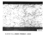
- FIG. 2D shows an annealed material (recrystallized material), and the aspect ratio (major axis / minor axis) approaches 1 when recrystallized.
- the microstructures in FIGS. 2A to 2D are microscopically observed at 1000 times after aqua regia etching.
- a steel foil such as SUS304 having a linear expansion coefficient at 0 to 100 ° C. exceeding 12.0 ⁇ 10 ⁇ 6 / ° C. is used as a substrate, a Cu (In 1-X Ga X ) Se 2 thin film (hereinafter referred to as a CIGS thin film).
- the linear expansion coefficient at 0 to 100 ° C. is desirably 12.0 ⁇ 10 ⁇ 6 / ° C. or less.
- mainly ferrite structures such as SUS430 and SUH409L and ferrite structures such as 9 mass% Cr steel having a ferrite structure are mainly used. It is preferable to make it an organization.
- the structure mainly composed of a ferrite structure means that the area ratio of ferrite is 95% or more.
- the steel foil for solar cell substrate according to the present invention contains 7 to 40% by mass of Cr, and after bright annealing or annealing with a thickness of 1 mm or less, a steel plate after pickling It can be manufactured by cold rolling at a reduction rate of 50% or more. This is because, as shown in FIG. 1, with SUS430 or the like, a tensile strength of 930 MPa or more can be obtained if the rolling reduction is 50% or more. If the rolling reduction is 70% or more, a tensile strength of 1000 MPa or more can be obtained.
- ferritic stainless steel such as SUS430 and SUH409L, 9 mass% Cr steel having a ferrite structure
- a steel plate after bright annealing having a ferrite structure such as, or after annealing and pickling may be used.
- N 2 gas, AX gas also referred to as ammonia decomposition gas
- NH 3 cracking gas 75 vol% H 2 +25 vol% N
- the heat treatment temperature is less than 400 ° C., such an effect is not exhibited. More preferably, it is 400 to 600 ° C.
- SUS430 (16% Cr) having the composition shown in Table 1 and 9% Cr steel, cold-rolled steel sheet having a thickness of 0.05 to 0.3 mm after bright annealing, and cold-rolled at the rolling reduction shown in Table 2
- a steel foil having a thickness of 30 to 50 ⁇ m, and after degreasing, as it is, or for some steel foils, after heat treatment at a heat treatment temperature shown in Table 2 in an N 2 gas atmosphere, multi-source deposition or It processed by the continuous process of the roll-to-Roll system of the solar cell which has the process of sputtering.
- SUS430, 11% Cr-1.5% Si steel and SUS304 having the composition shown in Table 1 are cold-rolled at a reduction ratio shown in Table 3 to form a steel foil having a thickness of 30 to 50 ⁇ m, and after degreasing, as it is, or Some of the steel foils were treated by a roll-to-roll continuous process of solar cells having a multi-source deposition or sputtering process after heat treatment at a heat treatment temperature shown in Table 3 in an N 2 gas atmosphere. Then, a tensile test perpendicular to the rolling direction was taken from the steel foil after cold rolling or heat treatment, and the tensile strength and elongation were measured, and the Vickers hardness (Hv) of the steel foil was measured.
- Hv Vickers hardness
Abstract
Description
本発明は、Roll−to−Roll方式の連続プロセスに適用しても、座屈の起こりにくい太陽電池基板用鋼箔およびその製造方法を提供することを目的とする。 However, when a stainless steel foil strip as described in Patent Document 4 is applied to a roll-to-roll type continuous process, buckling occurs in the foil strip, and the buckling portion rides on a roll and wrinkles ( There is a problem that wrinkle, broken surface, drawing, etc. are likely to occur.
An object of the present invention is to provide a steel foil for a solar cell substrate that hardly causes buckling even when applied to a roll-to-roll type continuous process, and a method for manufacturing the same.
本発明は、このような知見に基づきなされたもので、Crを7~40質量%含み、圧延方向に直角方向の引張強度が930MPa以上であることを特徴とする太陽電池基板用鋼箔を提供する。
本発明の太陽電池基板用鋼箔では、圧延方向に直角方向の引張強度が1000MPa以上であったり、ミクロ組織が圧延組織のままであることが好ましい。また、0~100℃における線膨張率が12.0×10⁻⁶/℃以下であったり、ミクロ組織がフェライト組織を主体とする組織であることが好ましい。
本発明である太陽電池基板用鋼箔は、Crを7~40質量%含み、厚さ1mm以下の光輝焼鈍後又は焼鈍し、酸洗後の鋼板を、圧下率(rolling reduction)50%以上で冷間圧延(cold rolling)することによって製造できる。このとき、圧下率70%以上で冷間圧延したり、フェライト組織(ferrite structure)を有する光輝焼鈍後または焼鈍し、酸洗後の鋼板を用いたり、冷間圧延後、不活性ガス雰囲気(inert gas atmosphere)中で400~700℃の熱処理を施すことが好ましい。
本発明は、また、上記の太陽電池基板用鋼箔を用いたことを特徴とする太陽電池基板や、この太陽電池基板を用いたことを特徴とする太陽電池を提供する。
本発明は、さらに、上記の太陽電池基板を用いてRoll−to−Roll方式の連続プロセスにより製造することを特徴とする太陽電池の製造方法を提供する。このとき、Roll−to−Roll方式の連続プロセスが、クリーニング−バック電極スパッタリング−太陽電池処理−セレン化処理−バッファー層形成−トップ電極スパッタリング−電極形成−スリットの工程を含むことが好ましい。 As a result of intensive studies to achieve the above object, the present inventors have found that steel containing 7 to 40% by mass of Cr and having a tensile strength in the direction perpendicular to the rolling direction of 930 MPa or more. It has been found that using foil is effective.
The present invention has been made on the basis of such knowledge, and provides a steel foil for a solar cell substrate containing 7 to 40% by mass of Cr and having a tensile strength in a direction perpendicular to the rolling direction of 930 MPa or more. To do.
In the steel foil for solar cell substrate of the present invention, it is preferable that the tensile strength in the direction perpendicular to the rolling direction is 1000 MPa or more, or the microstructure remains the rolled structure. Further, the linear expansion coefficient at 0 to 100 ° C. is preferably 12.0 × 10 −6 / ° C. or less, and the microstructure is preferably a structure mainly composed of a ferrite structure.
The steel foil for solar cell substrate according to the present invention contains 7 to 40% by mass of Cr, and after bright annealing or annealing with a thickness of 1 mm or less, the steel plate after pickling is at a rolling reduction of 50% or more. It can be manufactured by cold rolling. At this time, the steel sheet is cold-rolled at a rolling reduction of 70% or more, or after bright annealing or annealing with a ferrite structure (ferrite structure), and after pickling, or after cold rolling, an inert gas atmosphere (inert It is preferable to perform a heat treatment at 400 to 700 ° C. in a gas atmosphere).
The present invention also provides a solar cell substrate characterized by using the above-described steel foil for solar cell substrate, and a solar cell characterized by using this solar cell substrate.
The present invention further provides a method for manufacturing a solar cell, wherein the solar cell substrate is manufactured by a roll-to-roll continuous process. At this time, it is preferable that the roll-to-roll system continuous process includes the steps of cleaning, back electrode sputtering, solar cell treatment, selenization treatment, buffer layer formation, top electrode sputtering, electrode formation, and slitting.
本発明において、基材として使用する鋼箔については、太陽電池の基板で必要とされる耐食性を有する限り特段の制約は無い。ただし、Cr量が7質量%未満では長期使用時の耐食性(corrosion resistance)が不足しており、基板の腐食の問題があり、40質量%を超えると鋼箔製造における中間製品(partly−finished product)である熱延鋼板(hot rolled steel sheet)の靭性(toughness)が著しく低下し、製造ライン(manufacturing line)を通板することができなくなるという問題がある。そのため、Cr量は7~40質量%にする必要がある。こうした鋼としては、SUS430(17%Cr鋼)、SUS447J1(30%Cr−2%Mo鋼)、9%Cr鋼、20%Cr−5%Al鋼、SUS304(18%Cr−8%Ni鋼)などを挙げられる。
以下、特に好適な成分組成を示すと、次のとおりである。なお、鋼の成分組成を規定する成分%は、全て質量%を意味する。
C:0.12%以下
Cは、鋼中のCrと結合して、耐食性(corrosion resistance)の低下をもたらすため、低いほど望ましいが、0.12%以下であれば耐食性を著しく低下させることはない。このため、0.12%以下が好ましく、より好ましくは0.04%以下である。
Si:2.5%以下
Siは、脱酸(deoxidation)に用いる元素であるが、過剰に含有されると、延性の低下をもたらすため、2.5%以下が好ましい。より好ましくは1.0%以下である。
Mn:1.0%以下
Mnは、Sと結合してMnSを形成し、耐食性を低下させるため、1.0%以下が好ましい。より好ましくは0.8%以下である。
S:0.030%以下
上述したとおり、Sは、Mnと結合してMnSを形成し、耐食性を低下させるため、0.030%以下が好ましい。より好ましくは0.008%以下である。
P:0.050%以下
Pは、延性の低下をもたらすため、低いほど望ましいが、0.050%以下であれば延性を著しく低下させることはない。このため、0.050%以下が好ましく、より好ましくは0.040%以下である。
Cr:7%以上、40%以下
Cr量が7質量%未満では長期使用時の耐食性が不足しており、基板の腐食の問題があり、40質量%を超えると鋼箔製造における中間製品である熱延鋼板の靭性が著しく低下し、製造ラインを通板することができなくなるという問題がある。そのため、Cr量は7~40質量%にする必要がある。
以上、必須成分について説明したが、本発明では、その他にも以下に述べる元素を適宜含有させることができる。
Nb、Ti、Zrのうちから選んだ少なくとも一種を合計で:1.0%以下
Nb、Ti、Zrはいずれも、鋼中のC、Nを炭化物や窒化物、あるいは炭窒化物として固定し、耐食性を改善するのに有用な元素である。ただし、1.0%を超えて含有すると延性(ductility)の低下が顕著となるので、これらの元素は単独添加または複合添加いずれの場合も1.0%以下に限定する。なお、これらの元素の添加効果を十分に発揮させるには、0.02%以上含有させることが好ましい。
Al:0.20%以下
Alは、脱酸に用いられる元素であるが、過剰に含有されると延性の低下をもたらすため、0.20%以下が好ましい。より好ましくは、0.15%以下である。
N:0.05%以下
Nは、鋼中のCrと結合して、耐食性の低下をもたらすため、低いほど望ましいが、0.05%以下であれば耐食性を著しく低下させることはない。このため、0.05%以下が好ましい。より好ましくは0.015%以下である。
Mo:0.02%以上4.0%以下
Moは、鋼箔の耐食性、特に局部腐食性(localized corrosion)を改善するのに有効な元素であり、この効果を得るためには、0.02%以上含有させることが好ましい。一方、4.0%を超えて含有すると延性の低下が顕著となるので、上限は4.0%が好ましい。より好ましくは2.0%以下である。
また、その他にも、耐食性の改善を目的として、Ni、Cu、V、Wをそれぞれ1.0%以下で含有させることもできる。さらに熱間加工性(hot workability)の向上を目的として、Ca、Mg、REM(Rare Earth Metals)、Bをそれぞれ0.1%以下で含有させることもできる。
残部は、Feおよび不可避的不純物である。不可避的不純物のうちO(酸素)は、0.02%以下であることが好ましい。
太陽電池をRoll−to−Roll方式の連続プロセスにより製造するには、コイル状の基板用鋼箔を、例えば、クリーニング(cleaning)−バック電極スパッタリング(sputtering Mo back contact)−太陽電池処理(光吸収層形成(deposite absorber layer)−セレン化処理(selenization)−バッファー層形成(Cds buffer layer(chemical bath deposition))−トップ電極スパッタリング(sputtertop elctrode)−電極形成(deposite front electrode)−スリット(slitting)といった多くの工程で処理する必要がある。そのため、基板用鋼箔はロールによって何回も曲げ(bend)・曲げ戻し(unbend)の加工を受けるので座屈が起こりやすい状況に置かれている。特に、鋼箔の圧延方向に直角方向の引張強度が小さい(軟らかい)とロールを通過する時に圧延方向に平行な座屈によるシワ(バックリング)が発生する。この座屈の防止には、上述したように、基板用鋼箔の圧延方向に直角方向の引張強度を930MPa以上、好ましくは1000MPa以上にして箔の剛性(stiffness)を上げることが効果的である。
また、ミクロ組織は、図2A~図2Cに示すような圧延組織のままであることが好ましい。ここで、図2A~図2Cに示す圧延組織のままとは、冷間圧延のままあるいは、不活性ガス雰囲気中で400~700℃、0~5分の熱処理を施した組織を言い、圧延組織の一部または全てが、熱処理で再結晶しないで、扁平粒のまま残存した組織であるものをいう。圧延組織の体積率は、50vol%以上、好ましくは90vol%以上である。なお、図2Dは、焼鈍材(再結晶材)を示し、再結晶してしまうとアスペクト比(長軸÷短軸)がほぼ1に近くなる。図2A~図2Dのミクロ組織は、王水エッチング後1000倍で顕微鏡観察したものである。
さらに、SUS304などの0~100℃における線膨脹率が12.0×10⁻⁶/℃を超える鋼箔を基板に使用すると、Cu(In1−XGaX)Se2薄膜(以後、CIGS薄膜と呼ぶ)が基板との線膨脹率の違いで、製造中に剥離する問題が発生する。したがって、0~100℃における線膨脹率は12.0×10−6/℃以下とすることが望ましい。0~100℃における線膨脹率は12.0×10−6/℃以下とするためには、SUS430やSUH409Lなどのフェライト系ステンレス鋼、フェライト組織を有する9質量%Cr鋼などのフェライト組織を主体とする組織にすることが好ましい。フェライト組織を主体とする組織とは、フェライトの面積率が、95%以上であることを意味する。残部の組織は、オーステナイト組織、マルテンサイト組織の1種以上が、5%未満である。
2)太陽電池基板用鋼箔の製造方法
本発明である太陽電池基板用鋼箔は、Crを7~40質量%含み、厚さ1mm以下の光輝焼鈍後又は焼鈍し、酸洗後の鋼板を、圧下率50%以上で冷間圧延することによって製造できる。これは、図1に示すように、SUS430などでは圧下率を50%以上にすれば930MPa以上の引張強度が得られるためである。圧下率を70%以上にすれば1000MPa以上の引張強度が得られる。
また、0~100℃における線膨脹率を12.0×10⁻⁶/℃以下にする鋼箔にするためには、SUS430やSUH409Lなどのフェライト系ステンレス鋼、フェライト組織を有する9質量%Cr鋼などのフェライト組織を有する光輝焼鈍後又は焼鈍し、酸洗後の鋼板を用いればよい。
また、冷間圧延ままでも本発明の目的を達成できるが、冷間圧延後、N2ガス、AXガス(あるいは、アンモニア分解ガスとも称す)(NH3 cracking gas)(75vol%H2+25vol%N2)、H2ガス、HNガス(5vol%H2+95vol%N2)、Arガスなどの不活性ガス雰囲気中で400~700℃、0~5分の熱処理を施すと、時効硬化(age−hardening)によると考えられるが、更なる高強度化を図ることができ、座屈の防止により一層効果的である。熱処理温度(heat treatment temperature)が400℃未満ではこうした効果が発現されず、700℃を超えると軟化し、930MPa以上の引張強度が得られなくなる。さらに好ましくは、400~600℃である。 1) Steel foil for solar cell substrate In the present invention, the steel foil used as a base material is not particularly restricted as long as it has the corrosion resistance required for the substrate of the solar cell. However, if the Cr content is less than 7% by mass, the corrosion resistance during long-term use is insufficient, and there is a problem of corrosion of the substrate. If the Cr content exceeds 40% by mass, an intermediate product (partly-finished product) in steel foil production is present. ) Has a problem that the toughness of the hot rolled steel sheet is remarkably lowered, and the production line cannot be passed through. Therefore, the Cr amount needs to be 7 to 40% by mass. Such steels include SUS430 (17% Cr steel), SUS447J1 (30% Cr-2% Mo steel), 9% Cr steel, 20% Cr-5% Al steel, SUS304 (18% Cr-8% Ni steel). Etc.
Hereinafter, particularly preferred component compositions are as follows. In addition, all the component% which prescribes | regulates the component composition of steel means the mass%.
C: 0.12% or less C combines with Cr in steel, the corrosion resistance (corrosion resistance check) of the no al Sutame lowered, but low enough desired, remarkable reduction in corrosion resistance equal to or less than 0.12% I will not let you. For this reason, 0.12% or less is preferable, More preferably, it is 0.04% or less.
Si: 2.5% or less Si is an element used for deoxidation, but if contained excessively, ductility is lowered, so 2.5% or less is preferable. More preferably, it is 1.0% or less.
Mn: 1.0% or less Since Mn combines with S to form MnS and lowers the corrosion resistance, 1.0% or less is preferable. More preferably, it is 0.8% or less.
S: 0.030% or less As described above, S is combined with Mn to form MnS and lowers the corrosion resistance, so 0.030% or less is preferable. More preferably, it is 0.008% or less.
P: 0.050% or less P lowers the ductility, so it is desirable that it is lower. For this reason, 0.050% or less is preferable, More preferably, it is 0.040% or less.
Cr: 7% or more, 40% or less If the Cr amount is less than 7% by mass, the corrosion resistance during long-term use is insufficient, and there is a problem of corrosion of the substrate. If it exceeds 40% by mass, it is an intermediate product in steel foil production. There is a problem that the toughness of the hot-rolled steel sheet is remarkably lowered and the production line cannot be passed. Therefore, the Cr amount needs to be 7 to 40% by mass.
Although the essential components have been described above, in the present invention, other elements described below can be appropriately contained.
At least one selected from Nb, Ti, and Zr in total: 1.0% or less Nb, Ti, and Zr each fix C and N in steel as carbide, nitride, or carbonitride, It is an element useful for improving corrosion resistance. However, if the content exceeds 1.0%, the ductility decreases significantly, so these elements are limited to 1.0% or less in either case of single addition or composite addition. In addition, in order to fully exhibit the addition effect of these elements, it is preferable to make it contain 0.02% or more.
Al: 0.20% or less Al is an element used for deoxidation, but if it is excessively contained, ductility is lowered, so 0.20% or less is preferable. More preferably, it is 0.15% or less.
N: 0.05% or less N is combined with Cr in the steel to cause a decrease in corrosion resistance. Therefore, the lower the content, the better. However, if it is 0.05% or less, the corrosion resistance is not significantly reduced. For this reason, 0.05% or less is preferable. More preferably, it is 0.015% or less.
Mo: 0.02% or more and 4.0% or less Mo is an element effective for improving the corrosion resistance of steel foil, particularly localized corrosion, and in order to obtain this effect, 0.02% % Or more is preferable. On the other hand, if the content exceeds 4.0%, the ductility is remarkably lowered, so the upper limit is preferably 4.0%. More preferably, it is 2.0% or less.
In addition, Ni, Cu, V, and W can each be contained at 1.0% or less for the purpose of improving the corrosion resistance. Further, for the purpose of improving hot workability, Ca, Mg, REM (Rare Earth Metals), and B may be contained in each amount of 0.1% or less.
The balance is Fe and inevitable impurities. Of the inevitable impurities, O (oxygen) is preferably 0.02% or less.
In order to manufacture a solar cell by a roll-to-roll continuous process, a coiled steel foil for a substrate, for example, cleaning-back electrode sputtering (sputtering Mo back contact) -solar cell treatment (light absorption) Layer formation (deposite absorber layer)-selenization-buffer layer formation (Cds buffer layer)-top electrode sputtering (depositite strotrode)-electrode formation (deposite strotropel) It is necessary to process in many steps, so the steel foil for substrates Is also subjected to bending and unbending processing, so that buckling is likely to occur, especially when the tensile strength in the direction perpendicular to the rolling direction of the steel foil is small (soft). In order to prevent this buckling, as described above, the tensile strength in the direction perpendicular to the rolling direction of the substrate steel foil is preferably 930 MPa or more. It is effective to increase the stiffness of the foil by setting it to 1000 MPa or more.
Further, it is preferable that the microstructure remains the rolled structure as shown in FIGS. 2A to 2C. Here, the rolled structure shown in FIGS. 2A to 2C means a structure that has been cold-rolled or subjected to heat treatment at 400 to 700 ° C. for 0 to 5 minutes in an inert gas atmosphere. This is a structure in which a part or all of the structure remains as flat grains without being recrystallized by heat treatment. The volume ratio of the rolled structure is 50 vol% or more, preferably 90 vol% or more. FIG. 2D shows an annealed material (recrystallized material), and the aspect ratio (major axis / minor axis) approaches 1 when recrystallized. The microstructures in FIGS. 2A to 2D are microscopically observed at 1000 times after aqua regia etching.
Furthermore, when a steel foil such as SUS304 having a linear expansion coefficient at 0 to 100 ° C. exceeding 12.0 × 10 −6 / ° C. is used as a substrate, a Cu (In 1-X Ga X ) Se 2 thin film (hereinafter referred to as a CIGS thin film). However, due to the difference in the coefficient of linear expansion from the substrate, there arises a problem of peeling during manufacturing. Therefore, the linear expansion coefficient at 0 to 100 ° C. is desirably 12.0 × 10 −6 / ° C. or less. In order to set the linear expansion coefficient at 0 to 100 ° C. to 12.0 × 10 −6 / ° C. or less, mainly ferrite structures such as SUS430 and SUH409L and ferrite structures such as 9 mass% Cr steel having a ferrite structure are mainly used. It is preferable to make it an organization. The structure mainly composed of a ferrite structure means that the area ratio of ferrite is 95% or more. As for the remaining structure, at least one of an austenite structure and a martensite structure is less than 5%.
2) Manufacturing Method of Steel Foil for Solar Cell Substrate The steel foil for solar cell substrate according to the present invention contains 7 to 40% by mass of Cr, and after bright annealing or annealing with a thickness of 1 mm or less, a steel plate after pickling It can be manufactured by cold rolling at a reduction rate of 50% or more. This is because, as shown in FIG. 1, with SUS430 or the like, a tensile strength of 930 MPa or more can be obtained if the rolling reduction is 50% or more. If the rolling reduction is 70% or more, a tensile strength of 1000 MPa or more can be obtained.
In order to obtain a steel foil having a linear expansion coefficient at 0 to 100 ° C. of 12.0 × 10 −6 / ° C. or less, ferritic stainless steel such as SUS430 and SUH409L, 9 mass% Cr steel having a ferrite structure A steel plate after bright annealing having a ferrite structure such as, or after annealing and pickling may be used.
Although the object of the present invention can be achieved even with cold rolling, N 2 gas, AX gas (also referred to as ammonia decomposition gas) (NH 3 cracking gas) (75 vol% H 2 +25 vol% N) after cold rolling. 2 ), heat treatment at 400 to 700 ° C. for 0 to 5 minutes in an inert gas atmosphere such as H 2 gas, HN gas (5 vol% H 2 +95 vol% N 2 ), Ar gas, and the like. Although it is considered to be due to (hardening), it is possible to further increase the strength and is more effective in preventing buckling. When the heat treatment temperature is less than 400 ° C., such an effect is not exhibited. More preferably, it is 400 to 600 ° C.
結果を表2に示す。本発明例では、いずれも引張強度が930MPa以上であり、シワ発生がないことがわかる。また、冷間圧延後、本発明範囲内の熱処理温度(400~700℃)で熱処理することにより、引張強度を上昇できることがわかる。 SUS430 (16% Cr) having the composition shown in Table 1 and 9% Cr steel, cold-rolled steel sheet having a thickness of 0.05 to 0.3 mm after bright annealing, and cold-rolled at the rolling reduction shown in Table 2 A steel foil having a thickness of 30 to 50 μm, and after degreasing, as it is, or for some steel foils, after heat treatment at a heat treatment temperature shown in Table 2 in an N 2 gas atmosphere, multi-source deposition or It processed by the continuous process of the roll-to-Roll system of the solar cell which has the process of sputtering. Then, a tensile test perpendicular to the rolling direction is taken from the steel foil after cold rolling or heat treatment, and the tensile strength and elongation are measured, and the Vickers hardness (Hv) of the steel foil is measured. did. In addition, the occurrence of wrinkles during processing by a continuous process was visually examined.
The results are shown in Table 2. In the examples of the present invention, it can be seen that the tensile strength is 930 MPa or more and no wrinkle is generated. It can also be seen that after cold rolling, the tensile strength can be increased by heat treatment at a heat treatment temperature (400 to 700 ° C.) within the range of the present invention.
結果を表3に示す。本発明例では、いずれも引張強度が930MPa以上であり、シワ発生がないことがわかる。また、0~100℃における線膨脹率が12.0×10⁻⁶/℃以下である例では、CIGS薄膜剥離もないことがわかる


The results are shown in Table 3. In the examples of the present invention, it can be seen that the tensile strength is 930 MPa or more and no wrinkle is generated. Further, in the example where the linear expansion coefficient at 0 to 100 ° C. is 12.0 × 10 −6 / ° C. or less, it is understood that there is no CIGS thin film peeling.
Claims (13)
- Crを7~40質量%含み、圧延方向に直角方向の引張強度が930MPa以上であることを特徴とする太陽電池基板用鋼箔。 A steel foil for a solar cell substrate, comprising 7 to 40% by mass of Cr and having a tensile strength in a direction perpendicular to the rolling direction of 930 MPa or more.
- 圧延方向に直角方向の引張強度が1000MPa以上であることを特徴とする請求項1に記載の太陽電池基板用鋼箔。 The steel foil for solar cell substrate according to claim 1, wherein the tensile strength in the direction perpendicular to the rolling direction is 1000 MPa or more.
- ミクロ組織が圧延組織のままであることを特徴とする請求項1または2に記載の太陽電池基板用鋼箔。 The steel foil for solar cell substrate according to claim 1 or 2, wherein the microstructure remains a rolled structure.
- 0~100℃における線膨張率が12.0×10⁻⁶/℃以下であることを特徴とする請求項1~3のいずれか一項に記載の太陽電池基板用鋼箔。 The steel foil for a solar cell substrate according to any one of claims 1 to 3, wherein the linear expansion coefficient at 0 to 100 ° C is 12.0 × 10 -6 / ° C or less.
- ミクロ組織がフェライト組織を主体とする組織であることを特徴とする請求項1~4のいずれか一項に記載の太陽電池基板用鋼箔。 The steel foil for solar cell substrate according to any one of claims 1 to 4, wherein the microstructure is a structure mainly composed of a ferrite structure.
- Crを7~40質量%含み、厚さ1mm以下の光輝焼鈍後または焼鈍し、酸洗後の鋼板を、圧下率50%以上で冷間圧延することを特徴とする太陽電池基板用鋼箔の製造方法。 A steel foil for a solar cell substrate comprising 7 to 40% by mass of Cr, and after cold annealing or annealing with a thickness of 1 mm or less, and steel plate after pickling is cold-rolled at a reduction rate of 50% or more Production method.
- 圧下率70%以上で冷間圧延することを特徴とする請求項6に記載の太陽電池基板用鋼箔の製造方法。 The method for producing a steel foil for a solar cell substrate according to claim 6, wherein cold rolling is performed at a rolling reduction of 70% or more.
- フェライト組織を有する光輝焼鈍後または焼鈍し、酸洗後の鋼板を用いることを特徴とする請求項6または7に記載の太陽電池基板用鋼箔の製造方法。 The method for producing a steel foil for a solar cell substrate according to claim 6 or 7, wherein a steel plate after bright annealing having a ferrite structure or after annealing and pickling is used.
- 冷間圧延後、不活性ガス雰囲気中で400~700℃の熱処理を施すことを特徴とする請求項6から8のいずれか一項に記載の太陽電池基板用鋼箔の製造方法。 The method for producing a steel foil for a solar cell substrate according to any one of claims 6 to 8, wherein after the cold rolling, a heat treatment at 400 to 700 ° C is performed in an inert gas atmosphere.
- 請求項1~5のいずれか一項に記載の太陽電池基板用鋼箔を用いたことを特徴とする太陽電池基板。 A solar cell substrate using the steel foil for a solar cell substrate according to any one of claims 1 to 5.
- 請求項10に記載の太陽電池基板を用いたことを特徴とする太陽電池。 A solar cell using the solar cell substrate according to claim 10.
- 請求項10に記載の太陽電池基板を用いてRoll−to−Roll方式の連続プロセスにより製造することを特徴とする太陽電池の製造方法。 A method for manufacturing a solar cell, wherein the solar cell substrate according to claim 10 is used to manufacture by a roll-to-roll method continuous process.
- Roll−to−Roll方式の連続プロセスが、クリーニング−バック電極スパッタリング−太陽電池処理−セレン化処理−バッファー層形成−トップ電極スパッタリング−電極形成−スリットの工程を含むことを特徴とする請求項12に記載の太陽電池の製造方法。 The roll-to-roll system continuous process includes the steps of cleaning-back electrode sputtering-solar cell treatment-selenization treatment-buffer layer formation-top electrode sputtering-electrode formation-slit. The manufacturing method of the solar cell of description.
Priority Applications (4)
| Application Number | Priority Date | Filing Date | Title |
|---|---|---|---|
| KR1020137017635A KR101661019B1 (en) | 2010-12-10 | 2011-12-08 | Steel foil for solar cell substrate and manufacturing method therefor, and solar cell substrate, solar cell and manufacturing methods therefor |
| EP11846119.3A EP2650059A4 (en) | 2010-12-10 | 2011-12-08 | Steel foil for solar cell substrate, solar cell substrate, solar cell, and methods for manufacturing the steel foil and the solar cell |
| US13/992,846 US20140011044A1 (en) | 2010-12-10 | 2011-12-08 | Steel foil for solar cell substrate and manufacturing method therefor, and solar cell substrate, solar cell and manufacturing methods therefor |
| CN201180058623.9A CN103249502B (en) | 2010-12-10 | 2011-12-08 | Solar cell substrate steel foil, solar cell substrate, solaode and their manufacture method |
Applications Claiming Priority (4)
| Application Number | Priority Date | Filing Date | Title |
|---|---|---|---|
| JP2010-275653 | 2010-12-10 | ||
| JP2010275653 | 2010-12-10 | ||
| JP2011263517A JP5970796B2 (en) | 2010-12-10 | 2011-12-01 | Steel foil for solar cell substrate and manufacturing method thereof, and solar cell substrate, solar cell and manufacturing method thereof |
| JP2011-263517 | 2011-12-01 |
Publications (1)
| Publication Number | Publication Date |
|---|---|
| WO2012077827A1 true WO2012077827A1 (en) | 2012-06-14 |
Family
ID=46207304
Family Applications (1)
| Application Number | Title | Priority Date | Filing Date |
|---|---|---|---|
| PCT/JP2011/078981 WO2012077827A1 (en) | 2010-12-10 | 2011-12-08 | Steel foil for solar cell substrate, solar cell substrate, solar cell, and methods for manufacturing the steel foil and the solar cell |
Country Status (7)
| Country | Link |
|---|---|
| US (1) | US20140011044A1 (en) |
| EP (1) | EP2650059A4 (en) |
| JP (1) | JP5970796B2 (en) |
| KR (1) | KR101661019B1 (en) |
| CN (1) | CN103249502B (en) |
| TW (1) | TWI466305B (en) |
| WO (1) | WO2012077827A1 (en) |
Cited By (5)
| Publication number | Priority date | Publication date | Assignee | Title |
|---|---|---|---|---|
| WO2014148034A1 (en) | 2013-03-21 | 2014-09-25 | Jfeスチール株式会社 | Ferritic stainless steel foil for solar cell substrates |
| WO2014148035A1 (en) | 2013-03-21 | 2014-09-25 | Jfeスチール株式会社 | Ferritic stainless steel foil for solar cell substrates |
| JP5652568B1 (en) * | 2014-07-23 | 2015-01-14 | Jfeスチール株式会社 | Manufacturing method of ferritic stainless steel foil for solar cell substrate |
| JP5652567B1 (en) * | 2014-07-23 | 2015-01-14 | Jfeスチール株式会社 | Manufacturing method of ferritic stainless steel foil for solar cell substrate |
| JP2017172027A (en) * | 2016-03-25 | 2017-09-28 | 新日鐵住金ステンレス株式会社 | Al-CONTAINING FERRITIC STAINLESS STEEL AND PRODUCTION METHOD THEREFOR |
Families Citing this family (10)
| Publication number | Priority date | Publication date | Assignee | Title |
|---|---|---|---|---|
| EP2854184A4 (en) * | 2012-05-23 | 2015-09-23 | Jfe Steel Corp | Stainless steel foil solar cell substrate material and method for manufacturing same |
| JP5772806B2 (en) * | 2012-12-19 | 2015-09-02 | Jfeスチール株式会社 | Ferritic stainless steel sheet for solar cell member and method for producing the same |
| JP6392501B2 (en) | 2013-05-10 | 2018-09-19 | 新日鐵住金ステンレス株式会社 | Stainless steel substrate for solar cell with excellent insulation and small thermal expansion coefficient and method for producing the same |
| CN106795599B (en) * | 2014-08-29 | 2019-12-24 | 杰富意钢铁株式会社 | Ferritic stainless steel foil and method for producing same |
| DE102015102255A1 (en) * | 2015-02-17 | 2016-08-18 | Sandvik Materials Technology Deutschland Gmbh | Method for producing a strand of stainless steel and strand of stainless steel |
| US10844457B2 (en) * | 2015-08-17 | 2020-11-24 | Nippon Steel Chemical & Material Co., Ltd. | Ferritic stainless steel foil |
| JP6504973B6 (en) * | 2015-08-28 | 2019-05-29 | 日鉄ステンレス株式会社 | Al-containing ferritic stainless steel excellent in sulfide corrosion resistance and method for producing the same |
| CN111118404A (en) * | 2018-10-31 | 2020-05-08 | 北京铂阳顶荣光伏科技有限公司 | Stainless steel foil and preparation method thereof |
| JP6887459B2 (en) * | 2019-03-28 | 2021-06-16 | Jx金属株式会社 | Metal products and their manufacturing methods |
| WO2023188713A1 (en) * | 2022-03-31 | 2023-10-05 | 日鉄ケミカル&マテリアル株式会社 | Steel foil for current collector, and all-solid-state secondary cell |
Citations (8)
| Publication number | Priority date | Publication date | Assignee | Title |
|---|---|---|---|---|
| JPS63125614A (en) * | 1986-11-14 | 1988-05-28 | Nippon Mining Co Ltd | Production of austenitic stainless steel for thin leaf spring |
| JPS63138783A (en) * | 1986-12-01 | 1988-06-10 | Kawasaki Steel Corp | Manufacture of mother plate for solar cell substrate |
| JPS6472571A (en) | 1987-09-14 | 1989-03-17 | Kawasaki Steel Co | Manufacture of base plate for amorphous solar cell substrate |
| JPH05306460A (en) | 1992-05-01 | 1993-11-19 | Nippon Steel Corp | Production of insulating material coated with alumina film |
| JPH06299347A (en) | 1993-04-08 | 1994-10-25 | Nippon Steel Corp | Production of electric insulating platelike material |
| JP2004140143A (en) * | 2002-10-17 | 2004-05-13 | National Institute Of Advanced Industrial & Technology | Substrate for solar cell and solar cell |
| JP2006270024A (en) | 2005-02-28 | 2006-10-05 | Nippon Steel Corp | Covering stainless foil and silicon film solar battery |
| JP2010263037A (en) * | 2009-05-01 | 2010-11-18 | Fujifilm Corp | Metal composite substrate and method of producing the same |
Family Cites Families (18)
| Publication number | Priority date | Publication date | Assignee | Title |
|---|---|---|---|---|
| BE630167A (en) * | 1962-03-28 | |||
| US4022640A (en) * | 1974-01-18 | 1977-05-10 | Armco Steel Corporation | Process for cold-working and stress-relieving non-heat hardenable ferritic stainless steels |
| JPH07107178B2 (en) * | 1987-01-03 | 1995-11-15 | 日新製鋼株式会社 | Method for producing high strength dual phase chromium stainless steel strip with excellent ductility |
| ES2044905T3 (en) * | 1986-12-30 | 1994-01-16 | Nisshin Steel Co Ltd | PROCESS FOR THE PRODUCTION OF A CHROME STAINLESS STEEL BELT OF A DOUBLE STRUCTURE THAT HAS A HIGH STRENGTH AND EXTENSION AS WELL AS A BETTER FLAT ANISTROPY. |
| JP3176403B2 (en) * | 1991-12-20 | 2001-06-18 | 新日本製鐵株式会社 | High strength stainless steel foil for corrugating and method for producing the same |
| JP3125978B2 (en) * | 1995-12-05 | 2001-01-22 | 住友金属工業株式会社 | Method for producing high carbon steel strip with excellent workability |
| JPH09291311A (en) * | 1996-04-24 | 1997-11-11 | Nippon Steel Corp | Method and equipment for manufacturing hot rolled stainless steel plate excellent in surface characteristic and descaling property |
| JP3468172B2 (en) * | 1999-09-10 | 2003-11-17 | 住友金属工業株式会社 | High carbon steel strip excellent in cold workability and hardenability and method for producing the same |
| SE525704C2 (en) * | 2003-08-12 | 2005-04-05 | Sandvik Ab | Coated steel product of metal strip material comprising an electrically insulating layer doped with one or more alkali metals |
| JP5062985B2 (en) * | 2004-10-21 | 2012-10-31 | 新日鉄マテリアルズ株式会社 | High Al content steel plate with excellent workability and method for producing the same |
| JP3954607B2 (en) * | 2004-11-04 | 2007-08-08 | 株式会社神戸製鋼所 | Steel plate with less weld buckling deformation and its manufacturing method |
| JP2007009253A (en) * | 2005-06-29 | 2007-01-18 | Jfe Steel Kk | Method for manufacturing cold-rolled steel sheet having high yield ratio, high tensile strength and superior workability |
| ES2379384T3 (en) * | 2005-08-17 | 2012-04-25 | Jfe Steel Corporation | Ferritic stainless steel plate that has excellent corrosion resistance and its manufacturing process |
| JP5135868B2 (en) * | 2007-04-26 | 2013-02-06 | Jfeスチール株式会社 | Steel plate for can and manufacturing method thereof |
| JP5167487B2 (en) * | 2008-02-19 | 2013-03-21 | Jfeスチール株式会社 | High strength steel plate with excellent ductility and method for producing the same |
| US20100051105A1 (en) * | 2008-08-26 | 2010-03-04 | Mustafa Pinarbasi | Flexible substrate for ii-vi compound solar cells |
| JP2010114072A (en) * | 2008-10-10 | 2010-05-20 | Nisshin Steel Co Ltd | Dye-sensitized solar cell |
| CN101748339B (en) * | 2008-12-11 | 2012-03-28 | 宝山钢铁股份有限公司 | High-strength ferritic stainless steel band and manufacturing method thereof |
-
2011
- 2011-12-01 JP JP2011263517A patent/JP5970796B2/en active Active
- 2011-12-08 WO PCT/JP2011/078981 patent/WO2012077827A1/en active Application Filing
- 2011-12-08 EP EP11846119.3A patent/EP2650059A4/en not_active Withdrawn
- 2011-12-08 CN CN201180058623.9A patent/CN103249502B/en active Active
- 2011-12-08 TW TW100145340A patent/TWI466305B/en active
- 2011-12-08 US US13/992,846 patent/US20140011044A1/en not_active Abandoned
- 2011-12-08 KR KR1020137017635A patent/KR101661019B1/en active IP Right Grant
Patent Citations (8)
| Publication number | Priority date | Publication date | Assignee | Title |
|---|---|---|---|---|
| JPS63125614A (en) * | 1986-11-14 | 1988-05-28 | Nippon Mining Co Ltd | Production of austenitic stainless steel for thin leaf spring |
| JPS63138783A (en) * | 1986-12-01 | 1988-06-10 | Kawasaki Steel Corp | Manufacture of mother plate for solar cell substrate |
| JPS6472571A (en) | 1987-09-14 | 1989-03-17 | Kawasaki Steel Co | Manufacture of base plate for amorphous solar cell substrate |
| JPH05306460A (en) | 1992-05-01 | 1993-11-19 | Nippon Steel Corp | Production of insulating material coated with alumina film |
| JPH06299347A (en) | 1993-04-08 | 1994-10-25 | Nippon Steel Corp | Production of electric insulating platelike material |
| JP2004140143A (en) * | 2002-10-17 | 2004-05-13 | National Institute Of Advanced Industrial & Technology | Substrate for solar cell and solar cell |
| JP2006270024A (en) | 2005-02-28 | 2006-10-05 | Nippon Steel Corp | Covering stainless foil and silicon film solar battery |
| JP2010263037A (en) * | 2009-05-01 | 2010-11-18 | Fujifilm Corp | Metal composite substrate and method of producing the same |
Non-Patent Citations (1)
| Title |
|---|
| See also references of EP2650059A4 |
Cited By (11)
| Publication number | Priority date | Publication date | Assignee | Title |
|---|---|---|---|---|
| WO2014148034A1 (en) | 2013-03-21 | 2014-09-25 | Jfeスチール株式会社 | Ferritic stainless steel foil for solar cell substrates |
| WO2014148035A1 (en) | 2013-03-21 | 2014-09-25 | Jfeスチール株式会社 | Ferritic stainless steel foil for solar cell substrates |
| JP2014183255A (en) * | 2013-03-21 | 2014-09-29 | Jfe Steel Corp | Ferrite-based stainless foil for solar battery substrate use |
| JP2014183254A (en) * | 2013-03-21 | 2014-09-29 | Jfe Steel Corp | Ferrite-based stainless foil for solar battery substrate use |
| CN105051915A (en) * | 2013-03-21 | 2015-11-11 | 杰富意钢铁株式会社 | Ferritic stainless steel foil for solar cell substrates |
| CN105190912A (en) * | 2013-03-21 | 2015-12-23 | 杰富意钢铁株式会社 | Ferritic stainless steel foil for solar cell substrates |
| EP2953170A4 (en) * | 2013-03-21 | 2016-04-13 | Jfe Steel Corp | Ferritic stainless steel foil for solar cell substrates |
| EP2978029A4 (en) * | 2013-03-21 | 2016-05-04 | Jfe Steel Corp | Ferritic stainless steel foil for solar cell substrates |
| JP5652568B1 (en) * | 2014-07-23 | 2015-01-14 | Jfeスチール株式会社 | Manufacturing method of ferritic stainless steel foil for solar cell substrate |
| JP5652567B1 (en) * | 2014-07-23 | 2015-01-14 | Jfeスチール株式会社 | Manufacturing method of ferritic stainless steel foil for solar cell substrate |
| JP2017172027A (en) * | 2016-03-25 | 2017-09-28 | 新日鐵住金ステンレス株式会社 | Al-CONTAINING FERRITIC STAINLESS STEEL AND PRODUCTION METHOD THEREFOR |
Also Published As
| Publication number | Publication date |
|---|---|
| JP5970796B2 (en) | 2016-08-17 |
| CN103249502A (en) | 2013-08-14 |
| TWI466305B (en) | 2014-12-21 |
| EP2650059A4 (en) | 2017-03-29 |
| JP2012138571A (en) | 2012-07-19 |
| KR101661019B1 (en) | 2016-10-10 |
| KR20140074248A (en) | 2014-06-17 |
| EP2650059A1 (en) | 2013-10-16 |
| US20140011044A1 (en) | 2014-01-09 |
| CN103249502B (en) | 2016-12-14 |
| TW201240107A (en) | 2012-10-01 |
Similar Documents
| Publication | Publication Date | Title |
|---|---|---|
| WO2012077827A1 (en) | Steel foil for solar cell substrate, solar cell substrate, solar cell, and methods for manufacturing the steel foil and the solar cell | |
| JP6392501B2 (en) | Stainless steel substrate for solar cell with excellent insulation and small thermal expansion coefficient and method for producing the same | |
| EP3604594A1 (en) | Hot pressed member and method for manufacturing same | |
| RU2007118635A (en) | METHOD FOR PRODUCING CORROSION-RESISTANT COLD ROLLED SHEET FROM AUSTENITIC STEEL CONTAINING IRON, CARBON AND MANGANESE HAVING HIGH MECHANICAL PROPERTIES, AND TURNED OUT | |
| EP2103697A1 (en) | High carbon hot-rolled steel sheet and method for production thereof | |
| JP2011111674A (en) | HIGH STRENGTH COLD ROLLED STEEL SHEET EXCELLENT IN FATIGUE DURABILITY AND HAVING THE MAXIMUM TENSILE STRENGTH OF >=900 MPa AND METHOD FOR PRODUCING THE SAME, AND HIGH STRENGTH GALVANIZED STEEL SHEET AND METHOD FOR PRODUCING THE SAME | |
| EP3318649B1 (en) | Material for cold-rolled stainless steel sheets and manufacturing method therefor | |
| KR101699646B1 (en) | Stainless steel sheet and stainless steel foil | |
| KR102135839B1 (en) | Method for manufacturing steel sheet and continuous annealing device for steel sheet | |
| JP6653606B2 (en) | Al-containing ferritic stainless steel and method for producing the same | |
| JP2013014796A (en) | Stainless steel for polymer electrolyte fuel cell separator, method for producing the same, and polymer fuel electrolyte cell separator | |
| JP2006083403A (en) | High-strength cold rolled steel sheet with excellent ductility and chemical conversion treatability, and its manufacturing method | |
| WO2008013305A1 (en) | Stainless steel sheet for parts and process for manufacturing the same | |
| JP2019073783A (en) | Nb-CONTAINING FERRITIC STAINLESS STEEL MATERIAL EXCELLENT IN CORROSION RESISTANCE, AND MANUFACTURING METHOD | |
| TWI531664B (en) | Fertilizer iron-based stainless steel foil for solar cell substrate | |
| KR101747584B1 (en) | High-strength galvanized steel sheet and method for manufacturing the same | |
| WO2014148034A1 (en) | Ferritic stainless steel foil for solar cell substrates | |
| JP5652568B1 (en) | Manufacturing method of ferritic stainless steel foil for solar cell substrate | |
| JP4450700B2 (en) | Surface nitrided high-strength stainless steel strip excellent in delayed fracture resistance and method for producing the same | |
| JP6505415B2 (en) | Surface treatment method of Fe-Cr-Ni alloy material excellent in workability and corrosion resistance | |
| JP6159571B2 (en) | Stainless steel material for solar cell substrates with excellent insulation and low thermal expansion coefficient | |
| EP3342895B1 (en) | Al-containing ferritic stainless steel and method for manufacturing same | |
| CN114364820B (en) | Ferritic stainless steel with improved high temperature creep resistance and method for manufacturing same | |
| JP2016023343A (en) | Production method of ferritic stainless foil for solar cell substrate | |
| EP4253577A1 (en) | High-strength steel sheet and method for manufacturing same |
Legal Events
| Date | Code | Title | Description |
|---|---|---|---|
| 121 | Ep: the epo has been informed by wipo that ep was designated in this application |
Ref document number: 11846119 Country of ref document: EP Kind code of ref document: A1 |
|
| WWE | Wipo information: entry into national phase |
Ref document number: 2011846119 Country of ref document: EP |
|
| NENP | Non-entry into the national phase |
Ref country code: DE |
|
| ENP | Entry into the national phase |
Ref document number: 20137017635 Country of ref document: KR Kind code of ref document: A |
|
| WWE | Wipo information: entry into national phase |
Ref document number: 13992846 Country of ref document: US |