WO2012077615A1 - 通信装置、通信システム、通信方法、及びプロセッサ - Google Patents
通信装置、通信システム、通信方法、及びプロセッサ Download PDFInfo
- Publication number
- WO2012077615A1 WO2012077615A1 PCT/JP2011/078016 JP2011078016W WO2012077615A1 WO 2012077615 A1 WO2012077615 A1 WO 2012077615A1 JP 2011078016 W JP2011078016 W JP 2011078016W WO 2012077615 A1 WO2012077615 A1 WO 2012077615A1
- Authority
- WO
- WIPO (PCT)
- Prior art keywords
- communication device
- arrival
- angle
- correction information
- unit
- Prior art date
- Legal status (The legal status is an assumption and is not a legal conclusion. Google has not performed a legal analysis and makes no representation as to the accuracy of the status listed.)
- Ceased
Links
Images


Classifications
-
- H—ELECTRICITY
- H04—ELECTRIC COMMUNICATION TECHNIQUE
- H04B—TRANSMISSION
- H04B17/00—Monitoring; Testing
- H04B17/30—Monitoring; Testing of propagation channels
- H04B17/309—Measuring or estimating channel quality parameters
Definitions
- the present invention relates to a communication device, a communication system, a communication method, and a processor.
- MU-MIMO Multi-User Multi Input Multi Output
- Non-Patent Document A technique in which a base station apparatus transmits signals to a plurality of terminal apparatuses using a plurality of antennas at the same time and the same frequency is called Multi-User Multi Input Multi Output (MU-MIMO) (Non-Patent Document). 1).
- MU-MIMO Multi-User Multi Input Multi Output
- MUI multi-user interference
- MU-MIMO transmits a signal without MUI to each terminal device by removing this MUI in advance by the base station device.
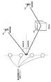
- FIG. 1 shows a communication system using beamforming.
- Base station apparatus 100 transmits signals simultaneously at a plurality of different angles by using antennas (linear array antennas) arranged in parallel and at equal intervals. Therefore, the base station apparatus 100 can multiplex a plurality of terminal apparatuses 200 and terminal apparatuses 300 only by grasping the directions of the terminal apparatuses 200 and 300.
- the base station apparatus 100 There are two methods for the base station apparatus 100 to know the directions of the terminal apparatus 200 and the terminal apparatus 300. One is a method of estimating using a sounding signal transmitted by a terminal device (see Patent Document 1). The other is a method in which the base station apparatus 100 receives an arrival angle notification from the terminal apparatus 200.
- each terminal device is expressed using “angle of arrival” in the sense that the signal from the terminal device reaches the base station device 100.
- FIG. 2 shows the definition of the angle of arrival.
- the arrival angle is an angle from a line orthogonal to a straight line passing through the antennas arranged in parallel in the base station apparatus.
- the terminal apparatus 200 has the arrival angle ⁇ 1 and the terminal apparatus 300 has the arrival angle ⁇ 2 .
- the terminal device uses a code book to notify the arrival angle.
- the code book is a precoding vector candidate shared in advance by the base station apparatus and the terminal apparatus.
- the terminal device can notify the base station device of the precoding vector requested by the terminal device only by notifying the number indicating the precoding vector in the codebook.
- each precoding vector corresponds to the arrival angle of the terminal apparatus.
- DFT matrix discrete Fourier transform matrix
- the terminal device notifying the base station device of a number indicating any one of the columns of the DFT matrix is equivalent to notifying the base station device of the arrival angle associated with Equation (1). It is.
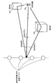
- FIG. 3 shows an example of a situation where a plurality of propagation paths exist.
- the signal transmitted from the terminal device 200 is reflected by the scatterer 400 such as a building and the scatterer 500 and is received by the base station device 100.
- the scatterer 400 or the scatterer 500 arrival angle ⁇ 11 or arrival angle ⁇ 12
- the direct wave arrival angle ⁇ from the terminal device 200. 13
- the angle of arrival is different. That is, it has a certain extent of arrival angle. This spread of arrival angles is called “angle spread”.
- the base station apparatus cannot grasp the correct propagation path state. Further, it is difficult for both the terminal device and the base station device to grasp the arrival angles of all paths without error. In particular, in a terminal device or a base station device, when there are more propagation paths than antennas, each propagation path cannot be separated, and it is impossible to correctly grasp the propagation path. Also, since the direction of the terminal device is not fixed to one, beam forming cannot be used.
- the base station apparatus can accurately grasp the propagation path state between the base station apparatus and the terminal apparatus with a minimum amount of control information.
- a communication apparatus that contributes to improvement of frequency utilization efficiency by improving the characteristics of MU-MIMO.
- the communication device is a first communication device having a plurality of antennas, and based on the arrival angle of the signal from the second communication device and the correction information notified by the second communication device, It has the propagation path state calculation part which calculates the propagation path state of a 2nd communication apparatus, It is characterized by the above-mentioned.
- the correction information may include information for correcting an error due to angular spread.
- the correction information may include information based on an error included in a response vector determined based on the angle of arrival.
- the correction information may include a coefficient of a primary error vector determined based on the angle of arrival.
- the propagation path state calculation unit includes an arrival angle acquisition unit that acquires the arrival angle, and a response vector corresponding to a propagation path between the first communication device and the second communication device based on the arrival angle.
- a first response vector calculation unit that calculates the correction information, a correction information acquisition unit that acquires the correction information, and a second response vector calculation unit that calculates a new response vector based on the correction information and the angle of arrival. May be.
- the response vector calculated by the second response vector calculation unit may be calculated by adding at least a vector obtained by multiplying the response vector calculated by the first response vector calculation unit by the coefficient and the primary error vector. .
- the correction information may include a coefficient corresponding to each of one or more error vectors determined based on the angle of arrival.
- the second response vector calculation unit may calculate a response vector by adding all the vectors obtained by multiplying the response vector calculated by the first response vector calculation unit by a coefficient corresponding to the error vector.
- the arrival angle acquisition unit may estimate the arrival angle based on a sounding signal transmitted by the second communication device.
- the arrival angle acquisition unit may acquire the arrival angle from the arrival angle information notified by the second communication device.
- Another communication device is a second communication device that communicates with a first communication device having a plurality of antennas, and the arrival of a signal from the second communication device in the first communication device.
- a feedback information generation unit that generates correction information based on a corner, and a transmission unit that notifies the first communication device of the correction information.
- the correction information may include information for correcting an error due to angular spread.
- the correction information may include information based on an error included in a response vector determined based on the angle of arrival.
- the correction information may include a coefficient of a primary error vector determined based on the angle of arrival.
- the feedback information generation unit obtains a response vector corresponding to a propagation path between the first communication device and the second communication device based on the arrival angle acquisition unit that acquires the arrival angle, and the arrival angle.
- a first response vector calculation unit to calculate, and a residual error to calculate an error from the propagation path between the first communication device and the second communication device of the response vector calculated by the first response vector calculation unit
- a primary error vector calculator that calculates a primary error vector based on the angle of arrival; a primary coefficient calculator that calculates a primary coefficient based on the residual error calculator and the primary error vector calculator;
- a correction information generation unit that generates the correction information based on the primary coefficient.
- the feedback information generation unit obtains a response vector corresponding to a propagation path between the first communication device and the second communication device based on the arrival angle acquisition unit that acquires the arrival angle, and the arrival angle.
- a first response vector calculation unit to calculate, and a residual error to calculate an error from the propagation path between the first communication device and the second communication device of the response vector calculated by the first response vector calculation unit A coefficient corresponding to each error vector is calculated based on a calculation unit, an error vector calculation unit that calculates one or more error vectors based on the angle of arrival, and the residual error calculation unit and the error vector calculation unit. You may have a coefficient calculation part and the correction information generation part which produces
- a communication system is a communication system including a first communication device having a plurality of antennas and one or more second communication devices, wherein at least a part of the second communication device includes the first communication device.
- a transmission unit that notifies the first communication device of correction information determined based on an arrival angle of a signal from the second communication device in the one communication device, and the first communication device includes the arrival angle.
- a propagation path state calculation unit for calculating a propagation path state of the second communication device based on the correction information.
- a communication method is a communication method in a first communication device having a plurality of antennas, wherein an angle of arrival of a signal from a second communication device in the first communication device and the second communication device are It has a step which calculates the propagation path state of said 2nd communication apparatus based on correction information to notify.
- Another communication method is a communication method in a second communication device that communicates with a first communication device having a plurality of antennas, and a signal from the second communication device in the first communication device.
- the processor according to the present invention is a processor in a first communication device having a plurality of antennas, and an arrival angle of a signal from a second communication device in the first communication device and a correction notified by the second communication device. It has a propagation path state calculation part which calculates the propagation path state of said 2nd communication apparatus based on information.
- Another processor is a processor in a second communication device that communicates with a first communication device having a plurality of antennas, based on the angle of arrival of the second communication device in the first communication device. And a transmission unit for notifying the first communication device of the correction information determined in this way.
- the base station apparatus can accurately grasp the propagation path state between the base station apparatus and the terminal apparatus with a minimum amount of control information. .
- the present invention notifies the terminal device (also referred to as a second communication device) of “information for correcting an error caused by the angular spread (correction information)”, thereby determining the propagation path state of the base station device.
- This is a technique for reducing errors.
- a base station apparatus also referred to as a first communication apparatus
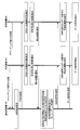
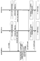
- FIG. 4 is a sequence diagram of the communication system in the present embodiment.
- the base station apparatus 100 multiplexes the terminal apparatus 200 and the terminal apparatus 300 as shown in FIG.
- the terminal devices 200 and 300 transmit a sounding signal.
- Base station apparatus 100 estimates the angle of arrival using the sounding signal.
- the base station apparatus 100 transmits a common reference signal (Common Reference Signal: CRS) to the terminal apparatus 200 and the terminal apparatus 300.
- CRS Common Reference Signal
- Each terminal apparatus estimates the propagation path state based on the CRS, and calculates correction information for correcting the error in the arrival angle and the angle spread from the estimation result.
- Terminal apparatus 200 and terminal apparatus 300 notify the correction information to the base station apparatus.
- CRS Common Reference Signal
- the base station apparatus calculates a vector representing the propagation path state of each terminal apparatus based on the arrival angle estimated from the sounding signal of each terminal apparatus and the correction information, and applies precoding to the signal of each terminal apparatus To do. Thereafter, the base station apparatus transmits a demodulation reference signal (DeModulation Reference Signal: DMRS) and a data signal to each terminal apparatus.
- DMRS demodulation Reference Signal
- Each terminal apparatus estimates an effective propagation path through which the data signal passes from a demodulation reference signal (DeModulation Reference Signal: DMRS), and the terminal apparatus 200 and the terminal apparatus 300 detect the data signal addressed to the terminal apparatus.
- the configuration of the base station device and the terminal device is shown. Thereafter, the propagation path state calculation unit and the feedback information generation unit, which are characteristic parts of the present embodiment, will be described in detail.
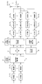
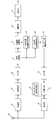
- FIG. 5 is a block diagram showing an example of the configuration of the base station apparatus in the present embodiment.
- the base station apparatus includes coding units 11 1 to 11 n , modulation units 12 1 to 12 n , eigen signal configuration unit 13, DMRM generation unit 14, reception units 15 1 to 15 n , and antennas 16 1 to 16.
- n Guard Interval (GI) removal units 17 1 to 17 n , FFT units 18 1 to 18 n , transmission path state calculation unit 19, filter calculation unit 20, precoding unit 21, frame A configuration unit 22, a CRS generation unit 23, IFFT units 24 1 to 24 n , GI insertion units 25 1 to 25 n , and transmission units 26 1 to 26 n are provided.
- GI Guard Interval
- the encoding units 11 1 to 11 n perform error correction encoding on the information bits addressed to the terminal devices, and input the encoded bits addressed to the terminal devices to the modulation units 12 1 to 12 n .
- Modulators 12 1 to 12 n modulate the input coded bits addressed to each terminal device to generate a data signal (modulated signal) addressed to each terminal device.
- the modulation units 12 1 to 12 n that have generated the data signal addressed to each terminal device input the data signal to the unique signal configuration unit 13.
- the DMRS generator 14 generates a DMRS addressed to each terminal device, and inputs the DMRS to the unique signal configuration unit 13.
- the unique signal configuration unit 13 configures a unique signal addressed to each terminal device using the modulated signal and DMRS.
- Receiving units 15 1 to 15 n receive signals including propagation path state information transmitted from each terminal device via antennas 16 1 to 16 n, and downconvert the signals including propagation path state information to perform base conversion. After generating the band digital signal, the baseband digital signal is input to the GI removal units 17 1 to 17 n .
- the GI removal units 17 1 to 17 n remove the GI from the baseband digital signal and input it to the FFT units 18 1 to 18 n .
- the FFT units 18 1 to 18 n perform FFT on the baseband digital signal from which the GI has been removed, calculate a frequency domain signal, and then input the frequency domain signal to the propagation path state calculation unit 19.
- the propagation path state calculation unit 19 generates a propagation path matrix from the signal in the frequency domain and inputs it to the filter calculation unit 20.
- the propagation path matrix represents a propagation path state of all terminal apparatuses that are spatially multiplexed in a matrix. Assuming that the number of terminal devices to be spatially multiplexed is n, the number of antennas of the base station device is n, and the number of antennas of the terminal device is 1, the propagation path matrix is a matrix of n rows and n columns. Each element indicates a propagation path gain between one antenna of the base station apparatus and one terminal apparatus. The operation of the propagation path state calculation unit will be described later. Note that the number of antennas of the base station apparatus and the number of terminal apparatuses may be different.
- the filter calculation unit 20 calculates a linear filter based on the propagation path state information and inputs the linear filter to the precoding unit 21.
- the filter calculation unit 20 may output an inverse matrix of the propagation path matrix as a linear filter based on a ZF (Zero Forcing) standard, or a minimum mean square error (MMSE) standard.
- a linear filter may be calculated.
- the precoding unit 21 may be so-called linear precoding using only the ZF filter or MMSE filter as described above, but may also be nonlinear precoding.
- Nonlinear precoding includes, for example, Tomlinson Harashima Precoding (THP), Lattice Reduction Aided-THP, or Vector Perturbation.
- the precoding unit 21 performs precoding by multiplying the unique signal addressed to the terminal device by a linear filter, generates a signal to be transmitted from each of the antennas 16 1 to 16 n, and inputs the signal to the frame configuration unit 22.
- the CRS generator 23 generates common reference signals (CRS) corresponding to each antenna and inputs the common reference signals (CRS) to the frame configuration unit 22.
- the frame configuration unit 22 uses the signals transmitted from the antennas 16 1 to 16 n input from the precoding unit 21, the CRS corresponding to the antennas 16 1 to 16 n , or both, and uses the antennas 16 1 to 16.
- the frame to be transmitted by n is generated and input to the IFFT units 24 1 to 24 n corresponding to the antennas 16 1 to 16 n .
- the IFFTs 24 1 to 24 n perform IFFT on the input frame, generate baseband digital signals, and input the baseband digital signals to the GI insertion units 25 1 to 25 n .
- the GI insertion units 25 1 to 25 n add a GI to the baseband digital signal, and input the signal with the GI added to the transmission units 26 1 to 26 n .
- the transmitting unit performs digital / analog conversion on the input signal, up-converts, generates a carrier frequency signal, and transmits the carrier frequency signal to the terminal device via the antennas 16 1 to 16 n. To do.
- FIG. 6 shows an example of the configuration of the unique signal in this embodiment.
- the base station apparatus transmits DMRSs (DMRS-MS1, DMRS-MS2,..., DMRS-MSn) addressed to each terminal apparatus at different times, and does not transmit DMRS and data signals at the same time.
- the base station apparatus transmits all data signals addressed to all terminal apparatuses at the same time.
- the data signal is transmitted after the DMRS addressed to all the terminal devices is transmitted.
- the time for transmitting the data signal and the time for transmitting the DMRS may be interchanged.
- Each part indicated by a rectangle such as “DMRS-MS1”) may be arranged alternately or in any order.
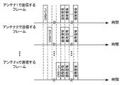
- FIG. 7 shows an example of a frame configuration in the present embodiment.
- each frame is a frame transmitted by each antenna.
- FIG. 7 shows frames transmitted at the same frequency in the same manner as in FIG.
- the CRSs (CRS-Tx1, CRS-Tx2,..., CRS-Txn) addressed to the terminal devices are transmitted at different times, and the CRS and the specific signal are not transmitted simultaneously. All the unique signals are transmitted simultaneously.
- the unique signal in FIG. 7 is a signal obtained by performing precoding on the unique signal shown for each terminal apparatus in FIG.
- the specific signal is transmitted after transmitting the CRS corresponding to the antenna.
- the time for transmitting the specific signal and the time for transmitting the CRS may be interchanged or may be alternated for each signal. Any order is acceptable.
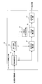
- FIG. 8 is a block diagram showing an example of the configuration of the terminal device in the present embodiment.
- n terminal devices are multiplexed, and all the n terminal devices have the configuration shown in FIG.
- the terminal device includes a receiving unit 27, an antenna 28, a GI removing unit 29, an FFT unit 30, a signal separating unit 31, a CRS channel estimating unit 32, a DMRS channel estimating unit 33, and a channel.
- a compensation unit 34, a feedback information generation unit 35, an IFFT unit 36, a GI insertion unit 37, a transmission unit 38, and a sounding signal generation unit 39 are provided.
- the receiving unit 27 receives a signal transmitted from the base station device via the antenna 28, down-converts it, generates a baseband digital signal, and then inputs the baseband digital signal to the GI removing unit 29.
- the GI removal unit 29 removes the GI from the baseband digital signal input from the reception unit 27 and inputs the GI to the FFT unit 30.
- the FFT 30 unit performs FFT on the baseband digital signal from which the GI has been removed, calculates a frequency domain signal, and then inputs the frequency domain signal to the signal separation unit 31.
- the signal separation unit 31 separates the CRS corresponding to each antenna of the base station device from the frequency domain signal and inputs the CRS to the channel estimation unit 32 for CRS. Further, the signal separation unit 31 separates the DMRS and inputs it to the DMRS propagation path estimation unit 33, separates the data signal, and inputs the data signal to the propagation path compensation unit 34.
- the CRS channel estimation unit 32 estimates the channel state from the base station apparatus to the terminal device based on the received CRS, and inputs information indicating the estimated channel state to the feedback information generation unit 35.
- the feedback information generation unit 35 calculates correction information using information indicating the propagation path state and inputs the correction information to the IFFT unit 36.
- the IFFT unit 36 performs IFFT on the signal input from the feedback information generation unit 35 to generate a baseband digital signal, and inputs the baseband digital signal to the GI insertion unit 37.
- the GI insertion unit 37 adds a GI to the baseband digital signal, and inputs the signal with the GI added to the transmission unit 38.
- the transmission unit 38 performs digital / analog conversion on the input propagation path state signal, and then up-converts to generate a radio signal having a carrier frequency, and transmits the signal to the base station device via the antenna 28. Send.
- the sounding signal generation unit 39 generates a sounding signal and inputs it to the transmission unit 38, and the transmission unit 28 transmits the signal to the base station apparatus via the antenna 28.
- the DMRS propagation path estimation unit 33 estimates a propagation path based on the input DMRS, and inputs information indicating the propagation path state to the propagation path compensation unit 34.
- the propagation path compensation unit 34 performs propagation path compensation on the data signal using information indicating the propagation path state and inputs the data signal to the demodulation unit 40.
- the demodulator 40 demodulates the data signal subjected to the modulo operation, and inputs the demodulation result to the decoder 41.
- the decoding unit 41 performs decoding using the input demodulation result and outputs information bits.
- the operation of the feedback information generating unit 35 of the terminal device will be described using the block diagram shown in FIG.
- the feedback information generation unit 35 includes an arrival angle acquisition unit 42, a first response vector calculation unit 43, a primary error vector calculation unit 44, a residual error calculation unit 45, a primary coefficient calculation unit 46, and a correction information generation unit 47.
- the arrival angle acquisition unit 42 obtains the arrival angle approximately on the assumption that the angular spread of the propagation path between the base station device and the terminal device is zero.
- the arrival angle acquisition unit 42 uses the regularity of the signals transmitted from the linear array arranged at a constant interval (for example, a half wavelength of the carrier wave), as “a propagation path state vector calculated only from the arrival angle”.
- the angle of arrival is obtained so that the error from the actual propagation path state vector is minimized.
- This “propagation state vector calculated only from the angle of arrival” is referred to as a first response vector.
- the transmission signal of the linear array is received by the terminal device while being shifted by a predetermined phase interval, and this phase interval depends on the arrival angle of the terminal device. By utilizing this, a propagation path state vector (first response vector) using only the arrival angle as a parameter can be calculated.
- is the norm of x
- A is a value indicating the amplitude and phase of the beam transmitted from the linear array of the base station apparatus. This A is represented by a complex number, and in Equation (3), the right side is minimized using A and ⁇ as parameters.
- the arrival angle acquisition unit 42 that has calculated the arrival angle by the procedure described above inputs the arrival angle information indicating the arrival angle to the first response vector calculation unit 43 and the primary error vector calculation unit 44.
- the arrival angle acquisition unit 42 calculates the vector h / A 0 using the value of A 0 when the right side is minimized in Equation (3), and inputs the vector h / A 0 to the residual error calculation unit 45.
- the vector h / A 0 is a vector indicating a propagation path state between each antenna of the base station apparatus and the terminal apparatus, and an equivalent propagation path including propagation path compensation with respect to phase rotation and amplitude change in the terminal apparatus. Therefore, the base station apparatus may grasp h / A 0 as the actual propagation path state that the terminal apparatus has. In other words, the present invention aims to provide a method for reducing the error of the propagation path state grasped by the base station apparatus and h / A 0 by notifying a slight amount of feedback information from the terminal apparatus. It is done.
- the first response vector calculation unit 43 substitutes ⁇ 0 into Expression (2) based on the input arrival angle ⁇ 0 to calculate f ( ⁇ 0 ), and the residual error calculation unit 45 as the first response vector. To enter.
- the residual error calculation unit 45 subtracts the first response vector f ( ⁇ 0 ) from the vector h / A 0 input from the arrival angle acquisition unit 42 to calculate the residual error ⁇ f, and the residual error ⁇ f is a primary coefficient. Input to the calculation unit 46.
- the primary error vector F ′ ( ⁇ 0 ) is a vector that approximately represents the direction of an error component that occurs as an error between the vector h / A 0 and the first response vector.
- the error due to the angular spread often occurs along the direction of the primary error vector, and is approximately a vector obtained by multiplying the primary error vector by a complex number B 1 (scalar value) as a coefficient.
- B 1 complex number
- the angles corresponding to the arrival angles of the paths are denoted by ⁇ 1 , ⁇ 2 , ⁇ 3 ,. . . , ⁇ L and the number of passes is L.
- the arrival angle of one path is ⁇ a
- the angle of arrival ( ⁇ with a suffix) and the corresponding angle ( ⁇ with a suffix) have the same relationship.
- the amplitude and phase of each path are represented by complex numbers c 1 , c 2 ,. . . , C L. Then, it can be developed as shown in the following equation using Taylor expansion.
- F (1) , F (2) , F (3) represent the first derivative, second derivative, third derivative... Of the function F, respectively.
- B 1 is proportional to the first power of the difference between the angles ⁇ 1 , ⁇ 2 , ⁇ 3 ,... And ⁇ 0 corresponding to the arrival angle of each path.
- B 2 is proportional to the square of the difference between the arrival angles ⁇ l , ⁇ 2 , ⁇ 3 ,... And ⁇ 0 of each path
- B 3 is an angle ⁇ l , ⁇ 2 corresponding to the arrival angle of each path.
- ⁇ 3 ,... And ⁇ 0 are proportional to the third power of the difference,. . . B 1 , B 2 ,. . .
- the coefficient decreases on average. This tendency is particularly noticeable when the angular spread is relatively small. Therefore, by feeding back to the base station apparatus information that can reproduce the first two terms on the right side of the last expression of Expression (6), the error from the vector h / A 0 that the base station apparatus should grasp is suppressed. The vector can be notified to the base station apparatus.
- the terminal device can reproduce Equation (5) that approximates h / A 0 .
- the base station apparatus can calculate the F ( ⁇ 0) and F '( ⁇ 0) from theta 0. Therefore, the base station apparatus can restore Equation (5) by notifying the remaining B 1 (hereinafter referred to as a primary coefficient) from the terminal apparatus to the base station apparatus.
- the primary error vector calculation unit 44 inputs the primary error vector F ′ ( ⁇ 0 ) to the primary coefficient calculation unit 46.
- the primary coefficient calculation unit 46 B 1 argmin
- a complex coefficient B 1 that satisfies the above is calculated. Equation (7) searches for the value of B that makes
- the primary coefficient calculation unit 46 After the calculation of Expression (7), the primary coefficient calculation unit 46 inputs the primary coefficient B 1 to the correction information generation unit 47. However, since it is actually necessary to quantize B 1 and notify it to the base station apparatus, it does not have to be completely minimum, and a quantization error may be included.
- Correction information generation unit 47 inputs the primary factor B 1 inputted from the primary coefficient calculating unit are quantized to generate the correction information, the IFFT unit 36 (FIG. 8).
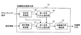
- the propagation path state calculation unit 19 includes an arrival angle acquisition unit 48, a first response vector calculation unit 49, a second response vector calculation unit 50, a correction information acquisition unit 51, and a propagation path matrix configuration unit 52.
- the arrival angle acquisition unit 48 acquires the arrival angle using the sounding signal. At this time, the method described in Patent Document 1 is used. However, the arrival angle estimation method is not limited to this. Another example is given. As described above, after the base station apparatus transmits CRS to the terminal apparatus for channel estimation, the terminal apparatus performs channel estimation based on the CRS, and uses the channel estimation result to determine the arrival angle. The angle of arrival is acquired by the acquisition unit 48 (FIG. 10). By transmitting a signal similar to the CRS from the terminal device as the sounding signal, the arrival angle can be estimated in the same manner in the base station device.
- the arrival angle acquisition unit 48 inputs the acquired arrival angle ⁇ 0 to the first response vector calculation unit 49 and the second response vector calculation unit 50.
- the first response vector calculation unit 49 calculates the first response vector using the arrival angle phi 0.
- a response vector f ( ⁇ 0 ) is calculated using an expression similar to Expression (2), and input to the second response vector calculation unit 50.
- the correction information acquisition unit 51 acquires the primary coefficient B 1 from the correction information notified from the terminal device and inputs it to the second response vector calculation unit 50.
- the second response vector calculation unit 50 includes an error vector calculation unit 53, an error calculation unit 54, and a vector addition unit 55.
- the primary error vector is input to the error calculator 54.
- the error calculation unit 54 inputs a vector obtained by multiplying the primary coefficient B 1 and the primary error vector F ′ ( ⁇ 0 ) to the vector addition unit 55.
- the vector addition unit 55 adds the vector input from the error calculation unit 54 to the first response vector to obtain a second response vector.
- the vector addition unit 55 inputs the second response vector to the propagation path matrix configuration unit 52 (FIG. 10).
- the propagation path matrix configuration unit 52 configures a propagation path matrix having the second response vector of each terminal device in a row, and inputs the propagation path matrix to the filter calculation unit 20 (FIG. 5).
- the base station apparatus can grasp the channel state more accurate than the conventional method of estimating the channel state from the arrival angle only by using the above method.
- only one value obtained by quantizing a complex number of scalar values needs to be sent from the terminal device, and an increase in uplink control information is minimized. Therefore, in the present embodiment, the base station apparatus can perform higher-quality transmission using accurate propagation path state information, and hardly changes the amount of information of uplink control information. This can contribute to improvement of frequency utilization efficiency.
- correction information is preferably calculated for each subcarrier and fed back to the base station apparatus.
- one correction information for a plurality of subcarriers may be calculated and fed back. If there is no frequency selectivity, only one correction information may be calculated for the entire band as in the case of the arrival angle.
- the base station apparatus estimates the arrival angle.
- the terminal apparatus estimates the arrival angle and notifies the base station.
- the present modification has the same configuration as that of the first embodiment described above, except for the portion related to the arrival angle. The configuration of this modification will be described with a focus on the angle of arrival.
- FIG. 12 is a sequence diagram of the communication system in the present modification.
- base station apparatus 100 transmits CRS to terminal apparatuses 200 and 300.
- the terminal apparatus first transmits a sounding signal to the base station apparatus.
- the sounding signal is not transmitted.
- the terminal devices 200 and 300 calculate the arrival angle and the correction information.
- the arrival angle and the correction information calculation method are the same as those in the first embodiment.
- each of the terminal devices 200 and 300 notifies the base station device 100 of both the arrival angle information and the correction information.
- the arrival angle is not notified in the first embodiment, it is notified in the present modification. Since the subsequent processes are the same as those in the first embodiment, description thereof will be omitted.
- the configuration of the terminal device according to this modification is shown in the block diagram of FIG.
- the terminal device is a receiving unit 27, an antenna 28, a GI removing unit 29, an FFT unit 30, a signal separating unit 31, a CRS channel estimating unit 32, and a DMRS channel estimating unit 33.
- a propagation path compensation unit 34 a feedback information generation unit 56, an IFFT unit 36, a GI insertion unit 37, and a transmission unit 38.
- the feedback information generation unit 56 calculates not only the correction information but also the arrival angle information and inputs it to the IFFT unit 36.
- the IFFT unit 36, the GI insertion unit 37, and the transmission unit 38 notify the base station apparatus of the arrival angle information and the correction information by a method similar to the method described in the first embodiment.
- FIG. 14 is a block diagram illustrating a detailed configuration of the feedback information generation unit 56 of the terminal device according to the present modification.
- the feedback information generation unit 56 includes an arrival angle acquisition unit 57, a first response vector calculation unit 43, a primary error vector calculation unit 44, a residual error calculation unit 45, a primary coefficient calculation unit 46, and a correction information generation unit 47.
- the arrival angle acquisition unit 57 outputs the arrival angle information.
- the terminal apparatus notifies the base station apparatus of the arrival angle information.
- the method of calculating the arrival angle and the method of calculating the correction information are the same as those in the first embodiment, and thus description thereof is omitted.
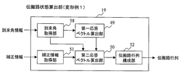
- FIG. 15 is a block diagram showing an internal configuration of the propagation path state calculation unit 19.
- the propagation path state calculation unit 19 includes an arrival angle acquisition unit 58, a first response vector calculation unit 49, a second response vector calculation unit 50, a correction information acquisition unit 51, and a propagation path matrix configuration unit 52.
- the arrival angle obtaining unit 58 estimates the arrival angle from the sounding signal, but the present modification is different only in that the arrival angle information notified from the terminal device is used.
- the accuracy of the propagation path state grasped by the base station apparatus can be improved by linearly approximating the propagation path state as compared with the conventional method in which only the arrival angle is estimated.
- the second embodiment a method of further improving accuracy by performing approximation of second order or higher will be described. Here, it is generally assumed that the Nth order approximation is obtained.
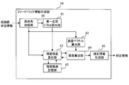
- FIG. 16 is a block diagram illustrating an example of a configuration of the feedback information generation unit 59 according to the present embodiment.
- the feedback information generation unit 59 includes an arrival angle acquisition unit 60, a first response vector calculation unit 61, an error vector calculation unit 62, a residual error calculation unit 63, a coefficient calculation unit 64, a residual error storage unit 65, A correction information generation unit 66.
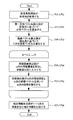
- FIG. 17 is a flowchart showing the operation of the feedback information generation unit 59.
- step S ⁇ b> 1 the arrival angle acquisition unit 60 calculates the arrival angle by the same method (Equation (3)) as in the first embodiment, and sends the arrival angle to the first response vector calculation unit 61 and the error vector calculation unit 62. Enter.
- the arrival angle acquisition unit 60 calculates the vector h / A 0 using the value of A 0 when the right side is minimized in Equation (3), and inputs the vector h / A 0 to the residual error calculation unit 63.
- step S2 the first response vector calculation unit 61 substitutes ⁇ 0 into Equation (2) based on the input arrival angle ⁇ 0 in the same manner as in the first embodiment, so that the first response vector f ( ⁇ 0 ) is calculated and input to the residual error calculator 63.
- the feedback information generation unit 59 repeats the following steps S4 and S5 N times.
- the variable representing the approximate order is set to m, and m is sequentially changed from 1 to N, and step S4 and step S5 are repeated.
- step S4 the residual error calculation unit 63 calculates the residual error ⁇ f and inputs it to the coefficient calculation unit 64.
- the first response vector f ( ⁇ 0 ) is subtracted from the vector h / A 0 input from the arrival angle acquisition unit 60 to calculate the residual error ⁇ f, and the residual error ⁇ f is calculated as a coefficient.
- the unit 64 and the residual error storage unit 65 To the unit 64 and the residual error storage unit 65.
- the residual error ⁇ f is acquired from the residual error storage unit 65, and the m ⁇ 1th order coefficient B m ⁇ 1 and the m ⁇ 1th order error vector F (m ⁇ 1) ( ⁇ 0 ) are used.
- ⁇ f ⁇ B m ⁇ 1 F (m ⁇ 1) ( ⁇ 0 ) is calculated.
- the vector is placed as a new residual error ⁇ f and input to the coefficient calculation unit 64 and the residual error storage unit 65.
- the complex coefficient B m satisfying the above is calculated. However, since it is actually necessary to quantize B m and notify the base station apparatus, it may not be completely minimized and may include a quantization error.
- the coefficient calculation unit 64 inputs the m-th order coefficient B m to the correction information generation unit 66 and the residual error calculation unit 63.
- the m-th order error vector F (m) ( ⁇ 0 ) is also input to the residual error calculation unit 63.
- step S6 the correction information generation unit 66 generates correction information including each of the subsequent coefficients B 1 to B N input from the coefficient calculation unit 64, and inputs the correction information to the IFFT unit 36 (FIG. 8).
- the above is the configuration and operation of the feedback information generation unit according to the present embodiment. Since the configuration of the terminal device according to the present embodiment is the same as that of the first embodiment, description thereof is omitted.
- the base station apparatus Since the base station apparatus has the same configuration as that of the first embodiment except for the propagation path state calculation unit, the description is omitted except for the propagation path state calculation unit.
- the configuration of the propagation path state calculation unit according to this embodiment is also shown in FIG.
- the correction information according to the present embodiment includes first to Nth order coefficients as described in the description of the operation of the terminal device.
- the correction information acquisition unit 51 inputs all the correction information to the second response vector calculation unit 50.
- the internal configuration of the second response vector calculation unit 50 according to the present embodiment is also represented in FIG. 11 as in the first embodiment. However, the operation of each component in the second response vector calculation unit 50 is different.
- the error vector calculation unit 53 according to the present embodiment based on the arrival angle input from the arrival angle acquisition unit 48 (FIG. 10), has error vectors F (1) ( ⁇ 0 ),. . . , F (N) ( ⁇ 0 ) is calculated.
- the error calculation unit 54 according to the present embodiment, based on each order coefficient input from the correction information acquisition unit 51 (FIG.
- vector B 1 F (1) ( ⁇ 0 ) + B 2 F (2) ( ⁇ 0 ) +. . . + B N F (N) ( ⁇ 0 ) is calculated.
- the error calculation unit 54 calculates the vector B 1 F (1) ( ⁇ 0 ) + B 2 F (2) ( ⁇ 0 ) +. . . + B N F (N) ( ⁇ 0 ) is input to the vector addition unit 55. Similar to the first embodiment, the vector adder 55 adds the first response vector F ( ⁇ 0 ) to the vector input from the error calculator 54 to calculate a response vector.
- the terminal apparatus notifies the base station apparatus of secondary coefficient to N coefficient B 2 to B N in addition to the primary coefficient B 1 as correction information. Thereby, it is possible to notify the base station apparatus of the propagation path state with higher accuracy than in the first embodiment.
- a method of notifying the arrival angle from the terminal device to the base station device may also be used.
- the sequence diagram of this modification is represented in FIG. 12
- the block diagram of the terminal apparatus is represented in FIG. 13
- the block diagram of the base station apparatus is represented in FIG. .
- the feedback information generator is shown in FIG. 18, and the propagation path state calculator is shown in FIG. FIG. 18 has the same configuration as that of the configuration diagram 16 of the second embodiment described above except that the arrival angle information acquisition unit 60 outputs the arrival angle information.
- the correction information is calculated for each subcarrier and fed back to the base station apparatus. It is desirable to do. However, in order to reduce the amount of uplink feedback information, one correction information for a plurality of subcarriers may be calculated and fed back. If there is no frequency selectivity, only one correction information may be calculated for the entire band as in the case of the arrival angle.
- the base station apparatus and the terminal apparatus share in advance a code book composed of a plurality of vectors, and the terminal apparatus uses the code book.
- the information indicating the vector number may be notified. For example, an oversampled DFT matrix
- M is a power of 2, such as 32.
- the total number of antennas included in the terminal device may be different from the number of data streams.
- the terminal apparatus and the base station apparatus may use an antenna as a process. You may treat it as one.
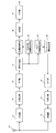
- a signal addressed to one terminal apparatus is duplicated into two, weighted to each, and physically transmitted from two sets of linear array antennas as shown in FIG. Even in such a case, the processing of the terminal device or the base station device may be treated as being transmitted from a set of linear array antennas.
- the program that operates in the terminal device and the base station device related to the present invention is a program that controls the CPU or the like (a program that causes a computer to function) so as to realize the functions of the above-described embodiments related to the present invention.
- Information handled by these devices is temporarily stored in the RAM at the time of processing, then stored in various ROMs and HDDs, read out by the CPU, and corrected and written as necessary.
- a recording medium for storing the program a semiconductor medium (for example, ROM, nonvolatile memory card, etc.), an optical recording medium (for example, DVD, MO, MD, CD, BD, etc.), a magnetic recording medium (for example, magnetic tape, Any of a flexible disk etc. may be sufficient.
- a semiconductor medium for example, ROM, nonvolatile memory card, etc.
- an optical recording medium for example, DVD, MO, MD, CD, BD, etc.
- a magnetic recording medium for example, magnetic tape, Any of a flexible disk etc.
- the program when distributing to the market, can be stored and distributed on a portable recording medium, or transferred to a server computer connected via a network such as the Internet.
- the storage device of the server computer is also included in the present invention.
- LSI which is typically an integrated circuit.
- Each functional block of the terminal apparatus and the base station apparatus may be individually made into a processor, or a part or all of them may be integrated into a processor.
- the method of circuit integration is not limited to LSI, and may be realized by a dedicated circuit or a general-purpose processor.
- an integrated circuit based on the technology can also be used.
- the present invention can be used for a communication device, a communication system, a communication method, and a processor.
Landscapes
- Engineering & Computer Science (AREA)
- Quality & Reliability (AREA)
- Physics & Mathematics (AREA)
- Electromagnetism (AREA)
- Computer Networks & Wireless Communication (AREA)
- Signal Processing (AREA)
- Radio Transmission System (AREA)
- Mobile Radio Communication Systems (AREA)
Applications Claiming Priority (2)
| Application Number | Priority Date | Filing Date | Title |
|---|---|---|---|
| JP2010-275708 | 2010-12-10 | ||
| JP2010275708A JP5785389B2 (ja) | 2010-12-10 | 2010-12-10 | 通信装置、通信システム、通信方法、及びプロセッサ |
Publications (1)
| Publication Number | Publication Date |
|---|---|
| WO2012077615A1 true WO2012077615A1 (ja) | 2012-06-14 |
Family
ID=46207103
Family Applications (1)
| Application Number | Title | Priority Date | Filing Date |
|---|---|---|---|
| PCT/JP2011/078016 Ceased WO2012077615A1 (ja) | 2010-12-10 | 2011-12-05 | 通信装置、通信システム、通信方法、及びプロセッサ |
Country Status (2)
| Country | Link |
|---|---|
| JP (1) | JP5785389B2 (enExample) |
| WO (1) | WO2012077615A1 (enExample) |
Cited By (1)
| Publication number | Priority date | Publication date | Assignee | Title |
|---|---|---|---|---|
| JP2016539525A (ja) * | 2013-09-27 | 2016-12-15 | 華為技術有限公司Huawei Technologies Co.,Ltd. | 通信方法、基地局およびユーザ機器 |
Families Citing this family (1)
| Publication number | Priority date | Publication date | Assignee | Title |
|---|---|---|---|---|
| US9439096B2 (en) * | 2012-08-13 | 2016-09-06 | Samsung Electronics Co., Ltd. | Method and apparatus to support channel refinement and multi-stream transmission in millimeter wave systems |
Citations (2)
| Publication number | Priority date | Publication date | Assignee | Title |
|---|---|---|---|---|
| JP2005064626A (ja) * | 2003-08-20 | 2005-03-10 | Hitachi Kokusai Electric Inc | 基地局装置 |
| JP2006094423A (ja) * | 2004-09-27 | 2006-04-06 | Matsushita Electric Ind Co Ltd | 移動通信システム、基地局装置、移動局装置、および移動通信システムのアンテナ校正方法 |
Family Cites Families (2)
| Publication number | Priority date | Publication date | Assignee | Title |
|---|---|---|---|---|
| JPH088814A (ja) * | 1994-06-23 | 1996-01-12 | Nippon Motorola Ltd | 移動無線通信方式 |
| CN101505205A (zh) * | 2008-02-05 | 2009-08-12 | 夏普株式会社 | 基于波达方向的开环mimo方法、基站及用户设备 |
-
2010
- 2010-12-10 JP JP2010275708A patent/JP5785389B2/ja active Active
-
2011
- 2011-12-05 WO PCT/JP2011/078016 patent/WO2012077615A1/ja not_active Ceased
Patent Citations (2)
| Publication number | Priority date | Publication date | Assignee | Title |
|---|---|---|---|---|
| JP2005064626A (ja) * | 2003-08-20 | 2005-03-10 | Hitachi Kokusai Electric Inc | 基地局装置 |
| JP2006094423A (ja) * | 2004-09-27 | 2006-04-06 | Matsushita Electric Ind Co Ltd | 移動通信システム、基地局装置、移動局装置、および移動通信システムのアンテナ校正方法 |
Cited By (2)
| Publication number | Priority date | Publication date | Assignee | Title |
|---|---|---|---|---|
| JP2016539525A (ja) * | 2013-09-27 | 2016-12-15 | 華為技術有限公司Huawei Technologies Co.,Ltd. | 通信方法、基地局およびユーザ機器 |
| US10009083B2 (en) | 2013-09-27 | 2018-06-26 | Huawei Technologies Co., Ltd. | Communication method, base station, and user equipment |
Also Published As
| Publication number | Publication date |
|---|---|
| JP2012124820A (ja) | 2012-06-28 |
| JP5785389B2 (ja) | 2015-09-30 |
Similar Documents
| Publication | Publication Date | Title |
|---|---|---|
| JP5599948B2 (ja) | マルチユーザ無線通信のための位相回転 | |
| EP3273629B1 (en) | Transmission device, reception device, control station, communication system, and transmission precoding method | |
| CN101542938B (zh) | 用于无线mimo通信系统中的隐式波束形成的校准校正 | |
| US9008677B2 (en) | Communication devices for multiple group communications | |
| US8229017B1 (en) | Transmit beamforming utilizing channel estimation matrix decomposition feedback in a wireless MIMO communication system | |
| US9191080B2 (en) | Reception device, transmission device, reception method, transmission method, program, and radio communication system | |
| US9362995B2 (en) | Transmitter apparatus, receiver apparatus, communication system, communication method, and integrated circuit | |
| US8391395B2 (en) | Precoder codebooks for effective channels with structured frequency-selectivity | |
| US9277556B2 (en) | Permitting a plurality of transmit antennas to transmit the same data to improve the reception quality through transmit diversity | |
| US20110080969A1 (en) | Multi-granular feedback reporting and feedback processing for precoding in telecommunications | |
| US9178587B2 (en) | Communication system, transmitter, receiver and communication method | |
| WO2012060177A1 (ja) | 基地局装置、移動局装置及びそれらを用いた無線通信システム | |
| CN103475609B (zh) | 通信设备、基带单元和通信方法 | |
| TWI404360B (zh) | 用於一多輸入多輸出正交分頻多工系統之通訊裝置及其方法 | |
| US10090898B2 (en) | Wireless communication system and method for forming a plurality of directed beams and precoding to adjust the received power at selected receiving apparatuses | |
| RU2766559C1 (ru) | Способ и устройство для передачи и приема информации о состоянии канала, узел связи и носитель данных | |
| WO2013168792A1 (ja) | 無線受信装置、無線送信装置、無線通信システム、プログラムおよび集積回路 | |
| JP5785389B2 (ja) | 通信装置、通信システム、通信方法、及びプロセッサ | |
| GB2452319A (en) | MIMO system with interpolation of precoder matrices from a subset of subcarriers | |
| JP5756636B2 (ja) | 無線通信システム、受信装置、送信装置 | |
| JP2017509213A (ja) | 情報処理装置、ネットワークノード、および情報処理方法 | |
| US12199710B2 (en) | Wireless communication method and wireless communication system |
Legal Events
| Date | Code | Title | Description |
|---|---|---|---|
| 121 | Ep: the epo has been informed by wipo that ep was designated in this application |
Ref document number: 11846185 Country of ref document: EP Kind code of ref document: A1 |
|
| NENP | Non-entry into the national phase |
Ref country code: DE |
|
| 122 | Ep: pct application non-entry in european phase |
Ref document number: 11846185 Country of ref document: EP Kind code of ref document: A1 |